JP5343367B2 - Control device for electric power steering device - Google Patents
Control device for electric power steering device Download PDFInfo
- Publication number
- JP5343367B2 JP5343367B2 JP2008048221A JP2008048221A JP5343367B2 JP 5343367 B2 JP5343367 B2 JP 5343367B2 JP 2008048221 A JP2008048221 A JP 2008048221A JP 2008048221 A JP2008048221 A JP 2008048221A JP 5343367 B2 JP5343367 B2 JP 5343367B2
- Authority
- JP
- Japan
- Prior art keywords
- motor
- wave signal
- abnormality
- rotation angle
- cos
- Prior art date
- Legal status (The legal status is an assumption and is not a legal conclusion. Google has not performed a legal analysis and makes no representation as to the accuracy of the status listed.)
- Expired - Fee Related
Links
Images


Description
本発明は、車両の操舵系にモータによるアシストトルク(操舵補助力)を付与するようにした電動パワーステアリング装置の制御装置に関し、特にモータのセンサ系の異常発生に対応してアシストを継続する電動パワーステアリング装置の制御装置に関する。 The present invention relates to a control device for an electric power steering device in which an assist torque (steering assist force) by a motor is applied to a steering system of a vehicle, and in particular, an electric motor that continues assisting in response to an abnormality occurring in a motor sensor system. The present invention relates to a control device for a power steering device.
車両のステアリング装置をモータの回転力で補助負荷付勢する電動パワーステアリング装置は、モータの駆動力を減速機を介してギア又はベルト等の伝達機構により、ステアリングシャフト或いはラック軸に補助負荷付勢するようになっている。かかる従来の電動パワーステアリング装置は、アシストトルクを正確に発生させるため、モータ電流のフィードバック制御を行っている。フィードバック制御は、電流指令値とモータ電流検出値との差が小さくなるようにモータ印加電圧を調整するものであり、モータ印加電圧の調整は、一般的にPWM(パルス幅変調)制御のデュ−ティ比の調整で行っている。 An electric power steering device for energizing a vehicle steering device with an auxiliary load by a rotational force of a motor energizes an auxiliary load to a steering shaft or a rack shaft by a transmission mechanism such as a gear or a belt via a speed reducer. It is supposed to be. Such a conventional electric power steering apparatus performs feedback control of motor current in order to accurately generate assist torque. In the feedback control, the motor applied voltage is adjusted so that the difference between the current command value and the motor current detection value becomes small. Generally, the adjustment of the motor applied voltage is a duty of PWM (pulse width modulation) control. This is done by adjusting the tee ratio.
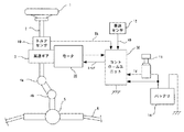
ここで、電動パワーステアリング装置の一般的な構成を図10に示して説明すると、ハンドル1のコラム軸2は減速ギア3、ユニバーサルジョイント4a及び4b、ピニオンラック機構5を経て操向車輪のタイロッド6に連結されている。コラム軸2には、ハンドル1の操舵トルクを検出するトルクセンサ10が設けられており、ハンドル1の操舵力を補助するモータ20が、減速ギア3を介してコラム軸2に連結されている。パワーステアリング装置を制御するコントロールユニット30には、バッテリ14から電力が供給されると共に、イグニッションキー11を経てイグニッション信号Igが入力され、コントロールユニット30は、トルクセンサ10で検出された操舵トルクThと車速センサ12で検出された車速Vhとに基づいてアシスト指令の操舵補助指令値Irefの演算を行い、演算された操舵補助指令値Irefに基づいてモータ20に供給する電流を制御する。
Here, the general configuration of the electric power steering apparatus will be described with reference to FIG. 10. The
コントロールユニット30は主としてCPU(MPUやMCUを含む)で構成されるが、そのCPU内部においてプログラムで実行される一般的な機能を、ベクトル制御方式について示すと図11のようになる。ベクトル制御は、ロータマグネットの座標軸であるトルクを制御するq軸と、磁界の強さを制御するd軸とを独立に設定し、各軸が90度の関係にある各軸の電流を制御するもので、モータ20は一般的に3相のブラシレスDCモータが使用される。
The
コントロールユニット30は電流指令値演算部31を具備しており、電流指令値演算部31はトルクセンサ10からの操舵トルクTh及び車速センサ12からの車速Vhを入力すると共に、ブラシレスDCモータ20に回転角センサとして取付けられたレゾルバ21の出力を、モータ回転角検出回路39で変換された回転角度θ及び角速度ωを入力し、アシストマップ32を参照してd−q軸の電流指令値Idref及びIqrefを演算する。
The
演算された電流指令値Iqref及びIdrefは減算部301及び302に入力され、減算部301及び302に対してモータ20の実際のモータ電流Iu、Iv、Iwを検出してフィードバック制御している。具体的には、電流検出器381及び382で2相のモータ電流Iu及びIwを検出し、3相の場合はIu+Iv+Iw=0の関係にあることから、減算部303においてモータ電流Ivを、Iv=−(Iu+Iw)として算出する。このようにして算出された3相のモータ電流Iu、Iv、Iwは、ベクトル制御のため3相/2相変換部33に入力され、モータ20の回転角度θに基づいてd−q軸のモータ電流iq及びidに変換される。
The calculated current command values Iqref and Idref are input to the
モータ電流iq及びidはそれぞれ減算部301及び302にフィードバックされ、減算部301で電流指令値Iqrefとモータ電流iqとの偏差ΔIqが算出され、減算部302で電流指令値Idrefとモータ電流idとの偏差ΔIdが算出される。これら偏差ΔIq及びΔIdはPI(比例積分)制御部35に入力され、PI制御された電圧指令値Vdref及びVqrefが出力される。そして、実際のモータ20には3相の電流を供給する必要があるので、電圧指令値Vdref及びVqrefを2相/3相変換部34で回転角度θに従って3相の電圧指令値Varef、Vbref、Vcrefに変換し、電圧指令値Varef、Vbref、VcrefをPWM制御部36に入力する。PWM制御部36は電圧指令値Varef、Vbref、Vcrefに基づいてPWM制御信号を発生し、インバータ回路37はこのPWM制御信号に基づきモータ20に電流Iu、Iv、Iwを供給し、偏差ΔIq及びΔIdをそれぞれ0とするようにモータ20を駆動制御する。また、バッテリ14からの電源電圧Vはインバータ37に入力されると共に、コントロールユニット30に入力される。
The motor currents iq and id are fed back to the
また、モータ回転角検出回路39は、モータ20の回転角度θを検出するために所定の周波数を有する搬送波信号sinωtをレゾルバ21に供給し、レゾルバ21はこの搬送波信号sinωtを正弦波sinθで振幅変調した波形を有する正弦波信号sinωt・sinθ及び搬送波信号sinωtを余弦波cosθで振幅変調した波形を有する余弦波信号sinωt・cosθを発生し、これら正弦波信号sinωt・sinθ及び余弦波信号sinωt・cosθをモータ回転角検出回路39で、搬送波信号sinωtの正のピーク時間に同期させて正弦波sinθ及び余弦波cosθを算出し、正弦波sinθ及び余弦波cosθに基づいてモータ20の回転角度θを検出する。
The motor rotation
上述したような電動パワーステアリング装置の制御装置において、モータの位置検出手段であるレゾルバやモータ回転角検出回路、モータ回転角検出回路の出力をA/D変換するA/D変換回路(以下、レゾルバ、モータ回転角検出回路及びA/D変換回路を単に「位置検出手段」とする。)に異常が発生した場合、モータの回転角度及び角速度を正しく検出できなくなるため、モータから検出される逆起電圧に基づいてモータの回転角度を推定し、継続してモータの駆動制御を行っていた。しかし、フェールセーフ用の冗長系としての用途には適していたが、モータの負荷変動等の影響により、滑らかな制御が極めて困難であった。 In the control device for the electric power steering apparatus as described above, a resolver that is a motor position detection means, a motor rotation angle detection circuit, and an A / D conversion circuit (hereinafter, resolver) for A / D converting the output of the motor rotation angle detection circuit. If the motor rotation angle detection circuit and A / D conversion circuit are simply referred to as “position detection means”), the rotation angle and angular velocity of the motor cannot be detected correctly. The rotation angle of the motor is estimated based on the voltage, and the drive control of the motor is continuously performed. However, it was suitable for use as a fail-safe redundant system, but smooth control was extremely difficult due to the influence of load fluctuations of the motor.
また、位置検出手段に異常が発生した場合、ハンドル操舵を突然マニュアル操舵に切替えると、ハンドル操舵に大きな違和感を与えてしまうため、異常の内容を解析し、モータが逆方向のトルクを出力する恐れがない等の条件に合わせて、アシストを継続或いは停止を切替えて制御していた。つまり、条件によってはアシストを停止していたという問題があった。 In addition, if an abnormality occurs in the position detection means, suddenly switching from steering to manual steering will cause a great sense of incongruity in steering, so the content of the abnormality may be analyzed and the motor may output reverse torque. The assist was controlled by switching between continuing or stopping according to the conditions such as the absence or the like. That is, there was a problem that the assist was stopped depending on conditions.
かかる問題を解決する装置として、例えば特開2003−164187号公報(特許文献1)に示されるモータ制御におけるセンサシステムがある。この特許文献1のセンサシステムでは、新たなセンサを設けることなく、冗長性を有するセンサシステムの構築を可能とし、センサの予期せぬ故障に対するフェールセーフを確保している。即ち、動作指令に従ってモータを駆動制御する駆動制御回路を備えるモータ駆動制御系において、モータの回転角度を検出するレゾルバを有するメイン角度検出手段と、モータの逆起電力に基づきモータの回転角度を推定するサブ角度検出手段とを備え、通常時はメイン角度検出手段でモータの回転角度を検出し、メイン角度検出手段の故障時にはサブ角度検出手段でモータの回転角度を検出している。
As an apparatus for solving such a problem, for example, there is a sensor system in motor control disclosed in Japanese Patent Laid-Open No. 2003-164187 (Patent Document 1). In the sensor system of
また、特開2005−168242号公報(特許文献2)に示される電動パワーステアリング装置では、電動パワーステアリング装置のモータの回転角度を検出するための角度検出手段が故障した場合でも、故障時のモータの回転角度の位置に拘らず電動パワーステアリング装置の制御を継続している。即ち、車両の操舵系にモータによる操舵補助力を付与するための制御に必要なモータの回転角度θを検出するため、所定周波数の搬送波信号sinωtを供給し、搬送波信号sinωtをsinθにより振幅変調した波形を有する正弦波信号sinωt・sinθ及びcosθにより振幅変調した波形を有する余弦波信号sinωt・cosθを発生する角度検出手器を具備する電動パワーステアリング装置の制御装置において、正弦波信号sinωt・sinθ及び余弦波信号sinωt・cosθからそれぞれsinθ及びcosθを抽出し、抽出されたcosθ及びsinθとから作成される回転角度信号を出力する角度処理手段を具備し、回転角度信号に基づいてモータが制御されている。
しかしながら、特許文献1の装置では、メイン角度検出手段とサブ角度検出手段とを備え、メイン角度検出手段に故障が発生した場合、サブ角度検出手段がモータの回転角度を推定している。つまり、サブ角度検出手段は、モータの回転角度を逆起電圧に基づいて推定しているため、モータの回転数が低い場合には推定誤差が大きくなってしまう問題が残っている。特に電動パワーステアリング装置では、停止、始動、正転、逆転を繰り返すような状況に対応しなければならないと共に、モータ回転数が低い状態で大きなトルクを必要とするため、レゾルバ等に異常が発生した場合であっても、信用性の高い回転角度を推定することが求められている。
However, the apparatus of
また、特許文献2の装置では、cos角度信号から作成される信号と、sin角度信号から作成される信号とから作成される回転角度信号を出力する角度処理手段を備えてフェールセーフを行っているが、増幅回路などの異常を検出する手段を備えていないため、さらなる改良が望まれている。
Further, the apparatus of
さらに近年では、電動パワーステアリング装置を搭載する車両の大型化に伴い、要求される電動パワーステアリング装置の高出力化が進み、モータトルクの増加、大電流化が加速している。このような高出力の電動パワーステアリング装置を備えた車両において、走行中にアシストを停止した場合、その反動がアシストの大きさに伴って大きく現れるため、運転者の負担も大きくなる。つまり、位置検出手段の異常発生であっても、できる限りアシストを継続することが求められている。 Furthermore, in recent years, with the increase in size of vehicles equipped with electric power steering devices, the required output of electric power steering devices has been increased, and the increase in motor torque and the increase in current have been accelerated. In a vehicle equipped with such a high-output electric power steering device, when the assist is stopped during traveling, the reaction appears greatly with the magnitude of the assist, so the burden on the driver also increases. In other words, it is required to continue assisting as much as possible even when an abnormality occurs in the position detection means.
本発明は上述のような事情によりなされたものであり、本発明の目的は、モータ位置検出手段に異常が発生した場合であっても、モータ位置を精度良く推定してアシストを継続する電動パワーステアリング装置の制御装置を提供することにある。 The present invention has been made for the above-described circumstances, and an object of the present invention is to provide an electric power that accurately estimates the motor position and continues the assist even when an abnormality occurs in the motor position detecting means. An object of the present invention is to provide a control device for a steering device.
本発明は、車両の操舵系をアシストするモータの回転位置を検出するレゾルバを備え、操舵トルク及び前記レゾルバからの正弦波信号sinθ及び余弦波信号cosθに基づいて前記モータを駆動制御する電動パワーステアリング装置の制御装置に関し、本発明の上記目的は、設定された閾値±αに対して、(1−α)<(sinθ 2 +cosθ 2 )<(1+α)に従って前記レゾルバの異常を検出する異常検出手段と、前記異常の検出時の前記レゾルバからの正弦波信号sinθのゼロクロス点における遷移の向き及び余弦波信号cosθの符号の関係、或いは余弦波信号cosθのゼロクロス点における遷移の向き及び正弦波信号sinθの符号との関係から、モータ方向を推定してモータ回転位置情報を出力する回転角度出力手段とを備え、正常時には前記レゾルバからの出力に基づいて前記アシストを行い、前記異常が検出されたときに、前記モータ回転位置情報に基づいて前記アシストを継続することにより達成される。 The present invention includes a resolver that detects a rotational position of a motor that assists a steering system of a vehicle, and an electric power steering that drives and controls the motor based on a steering torque, a sine wave signal sinθ and a cosine wave signal cosθ from the resolver. With respect to the control device of the apparatus, the above object of the present invention is to detect abnormality of the resolver according to (1−α) <(sin θ 2 + cos θ 2 ) <(1 + α) with respect to the set threshold value ± α. And the relationship between the direction of transition of the sine wave signal sinθ from the resolver at the time of detection of the abnormality and the sign of the cosine wave signal cosθ, or the direction of transition of the cosine wave signal cosθ at the zero cross point and the sine wave signal sinθ. Rotation angle output means for estimating the motor direction and outputting motor rotation position information from the relationship with the sign of This is achieved by performing the assist based on the above and continuing the assist based on the motor rotation position information when the abnormality is detected .
本発明の電動パワーステアリング装置の制御装置によれば、モータ回転位置を検出する位置検出手段の異常を効率良く検出すると共に、位置検出手段に異常が発生した場合であっても、新たなセンサを追加することなく、出力されている位置情報に基づいてモータの回転方向を推定し、推定された回転方向を反映させてモータ回転位置を精度良く推定することができる。このため、位置検出手段に異常が発生した場合でも、アシストを継続することができ、運転者の負担を抑制することができる。 According to the control device for the electric power steering apparatus of the present invention, it is possible to efficiently detect an abnormality of the position detection means for detecting the motor rotation position, and to detect a new sensor even when an abnormality occurs in the position detection means. Without adding, it is possible to estimate the rotational direction of the motor based on the output position information, and to accurately estimate the rotational position of the motor by reflecting the estimated rotational direction. For this reason, even when an abnormality occurs in the position detection means, the assist can be continued and the burden on the driver can be suppressed.
本発明に係る電動パワーステアリング装置の制御装置は、モータの回転位置を検出する位置検出手段の異常を効率良く検出すると共に、異常を検出した場合であっても、出力されている位置情報に基づいて実際のモータの回転方向を推定し、推定した回転方向を反映させて精度良くモータ回転位置を推定することで、アシストを継続するようにしている。 The control device for the electric power steering apparatus according to the present invention efficiently detects an abnormality of the position detecting means for detecting the rotational position of the motor, and based on the output position information even when the abnormality is detected. Thus, the actual rotation direction of the motor is estimated, and the estimated rotation direction is reflected to accurately estimate the motor rotation position, thereby continuing the assist.
先ず本発明の前提として、モータに取り付けられている位置検出手段に異常が発生した場合に、モータ回転位置を推定することによりアシストを継続する電動パワーステアリング制御装置の例(例えば特開2007−118823号)を図1に示して説明する。 First, as an assumption of the present invention, an example of an electric power steering control device that continues assist by estimating a motor rotation position when an abnormality occurs in a position detection unit attached to a motor (for example, Japanese Patent Application Laid-Open No. 2007-118823). No.) will be described with reference to FIG.
トルクセンサからの操舵トルクThは、保舵時振動検出手段46に入力されると共に、入力前処理手段41を介して平滑化処理手段42に入力される。保舵時振動検出手段46はノイズ除去のため進角ゲイン手段45の進角推定ゲインKmを感応制御し、入力された操舵トルクThに振動が発生していなければ、進角ゲイン手段45の進角推定ゲインKmを比較的大きく設定し、振動が発生している場合は、進角推定ゲインKmを比較的小さく設定する。
The steering torque Th from the torque sensor is input to the steering-holding
操舵トルクThが入力された平滑化処理手段42は、読込んだ操舵トルクThと過去分の所定数サンプリングとで平均化を行い、平均トルクTsMを算出して不感帯演算手段43に入力する。不感帯演算手段43は、予め設定された不感帯を検出する所定値と平滑化処理手段42において算出された平均トルクTsMとを比較し、不感帯内であれば平均トルクTsMを“0”として制限手段44に入力し、不感帯外であれば平均トルクTsMを制限手段44に入力する。
Steering torque Th is
制限手段44では入力された現在の平均トルクTsM(n)と、前回サンプリングされた平均トルクTsM(n−1)との変化量ΔTが演算され、さらに変化量ΔTと予め設定された設定変化量ΔTUとが比較され、設定変化量ΔTUを超えないように制限され、制限された平均値トルクTsMlim(n)が進角ゲイン手段45に入力される。
The limiting means 44 calculates a change amount ΔT between the input current average torque Ts M (n) and the previously sampled average torque Ts M (n−1), and further sets the change amount ΔT as a preset setting. The change amount ΔT U is compared, and the set change amount ΔT U is limited so as not to exceed the set change amount ΔT U , and the limited average torque Ts M lim (n) is input to the
進角ゲイン手段45は、車速Vhに基づいて低車速状態であるか或いは高車速状態であるか閾値を用いて判定し、車速Vhが停止状態を含む低車速状態であれば下記(1)式の演算を行い、モータの回転角変化量ΔθMを算出する。
ΔθM=TsMlim(n)・Km/212 ・・・(1)
また、車速Vhが高車速状態であれば、操舵追従性を考慮して下記(2)式の演算を行い、モータの回転角変化量ΔθMを算出する。
ΔθM=(TsMlim(n)・K/210+TsPH+Ts’)・Km/212・・・(2)
ここで、Kは定数、Kmは進角推定ゲイン、TsPHは操舵トルクThを位相補償した値、Ts’は操舵トルクThを微分してステアリングの中立点付近における応答性を高めるセンタ応答性改善値である。
進角ゲイン手段45において上記(1)式又は上記(2)式に基づいて演算されたモータの回転角変化量ΔθMは、前回サンプリング時に算出された回転角推定値θMP(n−1)と加算手段60にて加算処理され、算出されたモータの回転角推定値θMP(n)が切替手段49の接点C2に入力される。切替手段49の接点C1には、レゾルバ21及びモータ回転角検出回路39からの回転角度θが入力されている。
The advance angle gain means 45 determines whether the vehicle is in a low vehicle speed state or a high vehicle speed state based on the vehicle speed Vh using a threshold value. If the vehicle speed Vh is a low vehicle speed state including a stop state, the following equation (1) To calculate the rotation angle change amount Δθ M of the motor.
Δθ M = Ts M lim (n) · Km / 2 12 (1)
If the vehicle speed Vh is in a high vehicle speed state, the following equation (2) is calculated in consideration of the steering followability, and the rotation angle change amount Δθ M of the motor is calculated.
Δθ M = (Ts M lim (n) · K / 2 10 + Ts PH + Ts ′) · Km / 2 12 (2)
Here, K is a constant, Km is an advance angle estimation gain, Ts PH is a value obtained by phase compensation of the steering torque Th, and Ts ′ is a center response improvement that differentiates the steering torque Th to improve the response near the neutral point of the steering. Value.
The rotation angle change amount Δθ M of the motor calculated based on the above expression (1) or (2) in the advance angle gain means 45 is the estimated rotation angle θ MP (n−1) calculated at the previous sampling. Are added by the adding means 60, and the calculated rotation angle estimated value θ MP (n) of the motor is input to the contact C2 of the switching means 49. The rotation angle θ from the
切替手段49の切替信号CSは、レゾルバ21、モータ回転角検出回路39及びA/D変換回路の位置検出手段によって検出される正弦波信号sinθ及び余弦波信号cosθに基づいて、異常検出マップ(図示せず)によって正常/異常が検出されて入力されるようになっている。異常検出マップによって正常と判断されると、切替信号CSによって切替手段49の接点は“C1”に切替えられ、異常と判断されると、切替信号CSによって切替手段49の接点は“C2”に切替えられる。つまり、位置検出手段からの正弦波信号sinθ及び余弦波信号cosθの組合せが正常であれば、そのまま切替手段49の接点C1を介して電気角として出力され、異常であれば、切替手段49の接点C2を介して進角ゲイン手段45において推定されたモータ回転角推定値θMP(n)が電気角として出力される。
The switching signal CS of the switching means 49 is based on the sine wave signal sin θ and cosine wave signal cos θ detected by the position detector of the
次に、上述したような本発明の前提となる位置検出手段に異常が発生した場合に、位置検出手段の異常を効率よく検出し、回転方向を推定してモータ回転位置を推定する本発明の原理を以下に説明する。 Next, in the case where an abnormality occurs in the position detection unit as the premise of the present invention as described above, the abnormality of the position detection unit is efficiently detected, and the rotational direction is estimated to estimate the motor rotation position. The principle will be described below.
図2及び図3は、位置検出手段の1構成要素であるレゾルバ21によって検出される正弦波信号sinθ及び余弦波信号cosθの例を示す特性図であり、図2(a)は、モータ回転角検出回路39によって検出される正弦波信号sinθ及び余弦波信号cosθを所定時間毎に読込み、縦軸にsinを、横軸にcosをそれぞれプロットした特性を示し、原点G(0,0)を中心に3つの同心円を示している。実線で示されている半径“(sinθ)2+(cosθ)2=1”の同心円Dは、正常時における理想の正弦波信号sinθ及び余弦波信号cosθであり、点線で示されている半径(1+α)の同心円D1及び半径(1−α)の同心円D2は、それぞれ検出される正弦波信号sinθ及び余弦波信号cosθの異常を検出するための閾値を示している。例えば、位置検出手段を構成するレゾルバ21、モータ回転角検出回路39及びA/D変換回路のいずれかに異常が発生すると、検出される正弦波信号sinθ及び余弦波信号cosθに変化が生じ、例えば図2(b)の実線に示されるような特性になる。つまり、レゾルバ21のコイル部にショートが発生した場合や増幅回路に異常が発生した場合等、位置検出手段に異常が発生すると図2(b)の実線に示されるように、正弦波信号sinθ及び余弦波信号cosθのプロット特性は円形から変形し、例えば楕円軌道を描くようになるので、軌道の一部が半径(1+α)の同心円D1より大きくなったり、或いは半径(1−α)の同心円D2よりも小さくなったりし、このような場合を異常と判定するように閾値±αを予め設定する。このような閾値±αと、検出される正弦波信号sinθ及び余弦波信号cosθの関係式は、正弦波の2乗(sinθ)2をE2 sinとし、余弦波の2乗(cosθ)2をE2 cosとすると、下記(3)式に示されるようになる。
(1−α)<(E2 sin+E2 cos)<(1+α) ・・・(3)
上記(3)式の関係式を用いることにより、検出される位置情報の正常/異常を効率よく判定することができる。また、上記(3)式をマップ化することで、その都度演算する必要がないので、位置情報の正常/異常をさらに効率よく判定することができる。
2 and 3 are characteristic diagrams showing examples of the sine wave signal sin θ and the cosine wave signal cos θ detected by the
(1-α) <(E 2 sin + E 2 cos ) <(1 + α) (3)
By using the relational expression (3) above, normality / abnormality of detected position information can be determined efficiently. Further, by mapping the above equation (3), it is not necessary to calculate each time, so that the normal / abnormal position information can be determined more efficiently.
また、図3(a)は、図2(a)に対応する正弦波信号sinθと余弦波信号cosθの波形例を示しており、検出された正弦波信号sinθ及び余弦波信号cosθの出力レベルを示す振幅が同一で、余弦波信号cosθが正弦波信号sinθよりも位相が常に90°遅れている様子を示し、正弦波信号sinθ及び余弦波信号cosθがいずれも正常である状態を示している。また、図3(b)は、図2(b)に対応した正弦波信号sinθと余弦波信号cosθの波形例を示しており、検出された正弦波信号sinθ及び余弦波信号cosθの振幅及び位相に不揃いが生じ、異常が発生している状態を示している。 FIG. 3A shows a waveform example of the sine wave signal sin θ and the cosine wave signal cos θ corresponding to FIG. 2A, and the output levels of the detected sine wave signal sin θ and cosine wave signal cos θ are shown. The cosine wave signal cos θ has the same amplitude and the phase is always 90 ° behind the sine wave signal sin θ, and both the sine wave signal sin θ and the cosine wave signal cos θ are normal. FIG. 3B shows a waveform example of the sine wave signal sin θ and the cosine wave signal cos θ corresponding to FIG. 2B. The amplitude and phase of the detected sine wave signal sin θ and cosine wave signal cos θ. This shows a state where irregularities have occurred and an abnormality has occurred.
ここで、図2(b)及び図3(b)に示されるような異常が位置検出手段に発生した場合、検出される正弦波信号sinθ及び余弦波信号cosθから、その変化の方向と符号を判定することによって、モータの回転方向を推定することができる。以下に、モータの回転方向を推定する例を図4及び図5を参照して説明する。 Here, when an abnormality as shown in FIGS. 2B and 3B occurs in the position detection means, the direction and sign of the change are detected from the detected sine wave signal sin θ and cosine wave signal cos θ. By determining, the rotation direction of the motor can be estimated. Below, the example which estimates the rotation direction of a motor is demonstrated with reference to FIG.4 and FIG.5.
図4は、図2(b)に示されるような異常が発生した状態において、回転方向(CW、CCW)を推定する方法を説明するための特性図である。異常が検出された場合、図4に示されるように、正弦波信号sinθ或いは余弦波信号cosθがゼロを通過するゼロクロス点における正負の変遷を読取る。つまり、ゼロクロス点において正→負に変遷したか、又は負→正に変遷したかを読取る。そして、図5に示す正負の変遷時における符号の対応関係を示すフォーマット図に基づいて、正弦波信号sinθの正負の変遷に対する余弦波信号cosθの符号、或いは余弦波信号cosθの正負の変遷に対する正弦波信号sinθの符号の関係から回転方向(CW、CCW)を推定する。つまり、図4の回転P1では、正弦波信号sinθが正から負に変遷しており、余弦波信号cosθの符号が“−”であることから、図5(a)に示されるフォーマットの“sin正→負”から、モータの回転方向が“CW”であることを推定することができる。また、図4の回転P2では、余弦波信号cosθが負から正に変遷しており、正弦波sinθの符号が“+”であることから、図5(b)に示されるフォーマットの“cos負→正”から、モータの回転方向が“CCW”であることを推定することができる。 FIG. 4 is a characteristic diagram for explaining a method of estimating the rotation direction (CW, CCW) in a state where an abnormality as shown in FIG. 2B has occurred. When an abnormality is detected, as shown in FIG. 4, the positive and negative transitions at the zero cross point where the sine wave signal sin θ or the cosine wave signal cos θ passes zero are read. That is, it is read whether the transition is positive → negative or negative → positive at the zero cross point. Then, based on the format diagram showing the correspondence relationship of the signs at the time of the positive and negative transitions shown in FIG. The direction of rotation (CW, CCW) is estimated from the relationship of the sign of the wave signal sin θ. That is, at the rotation P1 in FIG. 4, the sine wave signal sin θ is changed from positive to negative, and the sign of the cosine wave signal cos θ is “−”, so that “sin” in the format shown in FIG. From “positive → negative”, it can be estimated that the rotation direction of the motor is “CW”. Further, in the rotation P2 in FIG. 4, the cosine wave signal cos θ is changed from negative to positive, and the sign of the sine wave sin θ is “+”. Therefore, the “cos negative” in the format shown in FIG. → From “Positive”, it can be estimated that the rotation direction of the motor is “CCW”.
このように、位置検出手段に異常が発生した場合であっても、実際に出力される位置検出手段の変遷情報から、精度良く効率的にモータ回転方向を推定することができる。つまり、位置検出手段に異常が検出された場合であっても、モータの回転数に関係なく、実際の位置検出手段の変遷情報から回転方向を確実に推定することができる。 As described above, even when an abnormality occurs in the position detection means, the motor rotation direction can be estimated accurately and efficiently from the transition information of the position detection means that is actually output. That is, even if an abnormality is detected in the position detection means, the direction of rotation can be reliably estimated from the transition information of the actual position detection means regardless of the rotational speed of the motor.
次に、上述の原理に基づいて、本発明の実施の形態を図面を参照して説明する。 Next, based on the above principle, an embodiment of the present invention will be described with reference to the drawings.
図6は本発明の構成例を図1に対応させて示すブロック図であり、同一部材には同一符号を付して説明を省略する。本発明では、図4及び図5で原理を説明した回転方向の推定を行って回転角度を出力する回転角度出力手段50と、図2及び図3で原理を説明した異常検出手段51とを新しく付加している。 FIG. 6 is a block diagram showing a configuration example of the present invention corresponding to FIG. 1, and the same members are denoted by the same reference numerals and description thereof is omitted. In the present invention, the rotation angle output means 50 that outputs the rotation angle by estimating the rotation direction explained in FIG. 4 and FIG. 5 and the abnormality detection means 51 explained in FIG. 2 and FIG. It is added.
モータ回転角検出回路39を経てレゾルバ21から正弦波信号sinθ及び余弦波信号cosθが回転角度出力手段50及び異常検出手段51に入力され、回転角度出力手段50は、入力された正弦波信号sinθ及び余弦波信号cosθに基づいて、図4に示したようなゼロクロス点における正負の変遷を読取り、図5に示す変遷時のフォーマットに基づいてモータの回転方向を推定し、回転方向を示す推定要素KKを求める。そして、進角ゲイン手段45から入力される回転角変化量ΔθMに推定要素KKを乗算することで回転方向を反映させ、回転方向を考慮した回転角変化量ΔθM・KKを加算手段70に入力する。加算手段70に入力された回転角変化量ΔθM・KKは、前回サンプリング時に算出された回転角推定値θMP(n−1)と加算手段70にて加算処理され、算出された回転角推定値θMP(n)は切替手段49の接点C2に入力される。
A sine wave signal sin θ and a cosine wave signal cos θ are input from the
また、異常検出手段51には、図2(a)で説明した閾値±αが予め設定されて入力されていると共に、上記(3)式に基づいたマップ化が施されており、レゾルバ21からの正弦波信号sinθ及び余弦波信号cosθの組合せに基づいて上記(3)式の異常判定が行われる。異常検出手段51の判定が正常であれば、切替手段49の接点を“C1”に切替える切替信号CSを出力し、異常であれば切替手段49の接点を“C2”に切替える切替信号CSを出力し、切替手段49の接点C1及びC2を切替える。つまり、レゾルバ21からの正弦波信号sinθ及び余弦波信号cosθの組合せが正常であれば、そのまま切替手段49の接点C1を介して電気角として出力し、異常であれば、切替手段49の接点C2を介して加算手段70からのモータの回転方向を考慮した回転角推定値θMP(n)を電気角として出力する。
In addition, the threshold value ± α described in FIG. 2A is set in advance and input to the abnormality detection means 51, and mapping based on the above equation (3) is performed. Based on the combination of the sine wave signal sin θ and the cosine wave signal cos θ, the abnormality determination of the above equation (3) is performed. If the determination of the abnormality detecting means 51 is normal, a switching signal CS for switching the contact of the switching means 49 to “C1” is output, and if abnormal, a switching signal CS for switching the contact of the switching means 49 to “C2” is output. Then, the contacts C1 and C2 of the switching means 49 are switched. That is, if the combination of the sine wave signal sin θ and the cosine wave signal cos θ from the
このように、位置検出手段に異常が発生した場合であっても、実際の位置検出手段の出力からモータの回転方向を推定して反映させたモータ回転角を出力することができるので、操舵トルクThの向きとモータの回転方向の不一致(例えばハンドル戻りや微操舵等)等が起こった場合でも、自然なアシストを継続することができる。 In this way, even if an abnormality occurs in the position detection means, the motor rotation angle that reflects the estimation of the motor rotation direction from the actual position detection means output can be output. Even when a mismatch between the direction of Th and the rotation direction of the motor (for example, steering wheel return or fine steering) occurs, natural assist can be continued.
なお、上述では、レゾルバ21からモータ回転角検出手段39を経て入力される正弦波信号sinθ及び余弦波信号cosθの組合せに基づいて異常を判定する例を説明したが、レゾルバ21から直接又はモータ回転角検出回路39のA/D変換回路からの正弦波信号sinθ及び余弦波信号cosθの組合せに基づいて異常判定を行うようにしても良い。
In the above description, the example in which the abnormality is determined based on the combination of the sine wave signal sin θ and the cosine wave signal cos θ input from the
次に、位置検出手段に半導体センサのホール素子、ホールIC等(以下、単に「ホールセンサ」とする)を用いた本発明の別の原理を以下に説明する。 Next, another principle of the present invention using a Hall element of a semiconductor sensor, a Hall IC or the like (hereinafter simply referred to as “Hall sensor”) as the position detection means will be described below.
ホールセンサを用いた位置検出手段は、モータに設けられたホールセンサからの検出信号が増幅回路等に入力され、増幅された検出信号に基づいて位置情報を検出するようになっている。つまり、位置情報として扱う検出信号の信号レベルが予め決められているので、位置検出手段が正常であるか或いは異常であるかを、上下限値の閾値を用いて検出信号の信号レベルを比較することにより判定する。例えば、検出信号の信号レベルを1〜4[V]の範囲で正常とした場合、下限閾値1[V]未満或いは上限閾値4[V]超では異常と判定する。このようなホールセンサHu、Hv、Hwからの検出信号Eu、Ev、Ewの信号レベルに対する閾値を、下限閾値Sl、上限閾値Shとすると、関係式は下記(4)式に示されるようになる。
Sl<(Eu,Ev,Ew)<Sh ・・・(4)
上記(4)式の関係式を用いることにより、検出される位置情報の正常/異常を効率よく判定することができる。
The position detection means using the hall sensor is configured such that a detection signal from the hall sensor provided in the motor is input to an amplifier circuit or the like, and position information is detected based on the amplified detection signal. That is, since the signal level of the detection signal handled as position information is determined in advance, the signal level of the detection signal is compared using the upper and lower limit threshold values to determine whether the position detection means is normal or abnormal. Judge by. For example, when the signal level of the detection signal is normal in the range of 1 to 4 [V], it is determined that the abnormality is present when the value is less than the lower threshold 1 [V] or exceeds the upper threshold 4 [V]. When the thresholds for the signal levels of the detection signals Eu, Ev, Ew from the hall sensors Hu, Hv, Hw are the lower limit threshold value Sl and the upper limit threshold value Sh, the relational expression is as shown in the following formula (4). .
Sl <(Eu, Ev, Ew) <Sh (4)
By using the relational expression (4) above, normality / abnormality of the detected position information can be determined efficiently.
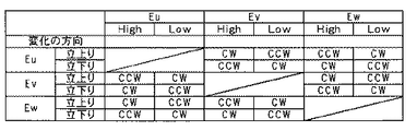
ここで、上記(4)式に基づいてホールセンサに異常が発生した場合、正常なホールセンサによって検出される立上り/立下りの検出信号とHigh/Low(以下、単に「H」/「L」)とする)の検出信号とを比較することによりモータの回転方向を推定することができる。以下に、位置検出手段にホールセンサを用いた場合、モータの回転方向を推定する例を図7及び図8を参照して説明する。 Here, when an abnormality occurs in the Hall sensor based on the above equation (4), a rising / falling detection signal detected by a normal Hall sensor and High / Low (hereinafter simply “H” / “L”). The rotation direction of the motor can be estimated by comparing with the detection signal of ()). Hereinafter, an example in which the rotation direction of the motor is estimated when a Hall sensor is used as the position detection means will be described with reference to FIGS.
図7は、例として3相ブラシレスモータのU相、V相、W相の極位置を検出するために120°間隔で設けられたホールセンサHu、Hv、Hwからの検出信号Eu、Ev、Ewの立上り/立下り及びH/Lの状態を、正常に検出している状態を示した信号波形図である。そして、図7に示されるホールセンサHu、Hv、Hwからの検出信号Eu、Ev、Ewのいずれか1つに断線等の異常が発生し、上記数(4)式に基づいて異常と判定された場合、検出される残りの正常なホールセンサからの検出信号の立上り/立下り及びH/Lの状態を読取り、図8に示す検出信号の立上り/立下りとH/Lの対応関係を示すフォーマット図に基づいて回転方向を推定する。つまり、例えばホールセンサHuからの検出信号Euに異常が発生した場合、図7のP4では、正常なホールセンサHvからの検出信号Evの立上りを検出し、その時の正常なホールセンサHwの検出信号Ewが「H」の状態であり、図8に示されるフォーマット図からモータの回転方向が“CW”であることを推定することができる。また、正常なホールセンサHvからの検出信号Evに異常が発生した場合、図7のP5では、ホールセンサHuからの検出信号Euの立下りを検出し、その時の正常なホールセンサHwの検出信号Ewが「H」の状態であり、回転図8に示されるフォーマット図からモータの回転方向が“CW”であることを検出することができる。 FIG. 7 shows detection signals Eu, Ev, Ew from Hall sensors Hu, Hv, Hw provided at intervals of 120 ° to detect the pole positions of the U phase, V phase, and W phase of a three-phase brushless motor as an example. It is the signal waveform diagram which showed the state which has detected the state of rising / falling of H, and the state of H / L normally. Then, an abnormality such as a disconnection occurs in any one of the detection signals Eu, Ev, and Ew from the hall sensors Hu, Hv, and Hw shown in FIG. 7, and the abnormality is determined based on the above equation (4). In this case, the rising / falling of the detection signal from the remaining normal hall sensors to be detected and the H / L state are read, and the correspondence between the rising / falling of the detection signal and H / L shown in FIG. 8 is shown. The direction of rotation is estimated based on the format diagram. That is, for example, when an abnormality occurs in the detection signal Eu from the hall sensor Hu, the rise of the detection signal Ev from the normal hall sensor Hv is detected at P4 in FIG. 7, and the detection signal from the normal hall sensor Hw at that time is detected. Ew is in the “H” state, and it can be estimated from the format diagram shown in FIG. 8 that the rotation direction of the motor is “CW”. If an abnormality occurs in the detection signal Ev from the normal hall sensor Hv, the fall of the detection signal Eu from the hall sensor Hu is detected at P5 in FIG. 7, and the detection signal from the normal hall sensor Hw at that time is detected. It can be detected that Ew is in the “H” state and the rotation direction of the motor is “CW” from the format diagram shown in FIG.
このように、ホールセンサからの位置情報に異常が検出された場合であっても、モータの回転数に関係なく実際のホールセンサから回転方向を検出することができるため、モータ回転位置情報の推定精度を向上することができる。 In this way, even if anomaly is detected in the position information from the Hall sensor, the rotation direction can be detected from the actual Hall sensor regardless of the motor rotation speed, so estimation of the motor rotation position information is possible. Accuracy can be improved.
上述の原理に基づく本発明の別の構成例を、図6に対応させて図9に示して説明する。 Another configuration example of the present invention based on the above principle will be described with reference to FIG. 9 corresponding to FIG.
モータ20に設けられたホールセンサ(Hu、Hv、Hw)21Aからの検出信号Eu、Ev、Ewが回転角度出力手段60及び異常検出手段61に入力され、回転角度出力手段60は、入力された検出信号Eu、Ev、Ewに基づいて、図7に示したような立上り/立下りにおけるH/Lを読取り、図8に示す立上り/立下りとH/Lの対応関係のフォーマットに基づいてモータ20の回転方向を推定し、回転方向を示す推定要素KKを求める。そして、進角ゲイン手段45から入力される回転角変化量ΔθMに推定要素KKを乗算することで、回転方向を反映させ、回転方向を考慮した回転角変化量ΔθM・KKを加算手段70に入力する。
Detection signals Eu, Ev, Ew from a hall sensor (Hu, Hv, Hw) 21A provided in the
また、異常検出手段61には上記数(4)式の下限閾値Sl及び上限閾値Shが予め設定されており、異常検出手段61はホールセンサ21Aからの検出信号Eu、Ev、Ewに基づいて上記(4)式の異常判定を行う。異常検出手段61の判定が正常であれば、切替手段49の接点を“C1”に切替える切替信号CSを出力し、異常であれば切替手段49の接点を“C2”に切替える切替信号CSを出力し、切替手段49の接点C1及びC2を切替える。つまり、ホールセンサ21Aからの検出信号Eu、Ev、Ewが正常であれば、そのまま切替手段49の接点C1を介して電気角として出力し、異常であれば、切替手段49の接点C2を介して加算手段70からのモータ20の回転方向を考慮した回転角推定値θMP(n)を電気角として出力する。
Further, the lower limit threshold value Sl and the upper limit threshold value Sh of the above equation (4) are set in advance in the abnormality detection means 61, and the abnormality detection means 61 is based on the detection signals Eu, Ev, Ew from the
このように、位置検出手段に異常が発生した場合であっても、実際のモータ20の回転方向を推定して反映させたモータ回転角を出力することができるので、操舵トルクThの向きとモータ20の回転方向の不一致(例えばハンドル戻りや微操舵等)等が起こった場合でも、自然なアシストを継続することができる。
As described above, even when an abnormality occurs in the position detection means, the motor rotation angle that is obtained by estimating the actual rotation direction of the
1 ハンドル
2 コラム軸
10 トルクセンサ
12 車速センサ
20 モータ
21 レゾルバ
21A ホールセンサ
39 モータ回転角検出回路
43 不感帯演算手段
44 制限手段
45 進角ゲイン手段
46 保舵時振動検出手段
49 切替手段
50、60 回転角度出力手段
51、61 異常検出手段
DESCRIPTION OF
Claims (1)
設定された閾値±αに対して、(1−α)<(sinθ2+cosθ2)<(1+α)に従って前記レゾルバの異常を検出する異常検出手段と、
前記異常の検出時の前記レゾルバからの正弦波信号sinθのゼロクロス点における遷移の向き及び余弦波信号cosθの符号の関係、或いは余弦波信号cosθのゼロクロス点における遷移の向き及び正弦波信号sinθの符号との関係から、モータ方向を推定してモータ回転位置情報を出力する回転角度出力手段と、
を備え、正常時には前記レゾルバからの出力に基づいて前記アシストを行い、前記異常が検出されたときに、前記モータ回転位置情報に基づいて前記アシストを継続することを特徴とする電動パワーステアリング装置の制御装置。 A control device for an electric power steering apparatus, comprising a resolver that detects a rotational position of a motor that assists a steering system of a vehicle, and that drives and controls the motor based on a steering torque, a sine wave signal sinθ and a cosine wave signal cosθ from the resolver In
An abnormality detecting means for detecting an abnormality of the resolver according to (1-α) <(sinθ 2 + cos θ 2 ) <(1 + α) with respect to the set threshold value ± α;
Relationship between the direction of transition at the zero cross point of the sine wave signal sin θ from the resolver and the sign of the cosine wave signal cos θ at the time of detecting the abnormality, or the direction of transition at the zero cross point of the cosine wave signal cos θ and the sign of the sine wave signal sin θ The rotation angle output means for estimating the motor direction and outputting the motor rotation position information,
An electric power steering apparatus, wherein the assist is performed based on an output from the resolver in a normal state, and the assist is continued based on the motor rotational position information when the abnormality is detected. Control device.
Priority Applications (1)
| Application Number | Priority Date | Filing Date | Title |
|---|---|---|---|
| JP2008048221A JP5343367B2 (en) | 2008-02-28 | 2008-02-28 | Control device for electric power steering device |
Applications Claiming Priority (1)
| Application Number | Priority Date | Filing Date | Title |
|---|---|---|---|
| JP2008048221A JP5343367B2 (en) | 2008-02-28 | 2008-02-28 | Control device for electric power steering device |
Publications (3)
| Publication Number | Publication Date |
|---|---|
| JP2009202774A JP2009202774A (en) | 2009-09-10 |
| JP2009202774A5 JP2009202774A5 (en) | 2010-12-16 |
| JP5343367B2 true JP5343367B2 (en) | 2013-11-13 |
Family
ID=41145467
Family Applications (1)
| Application Number | Title | Priority Date | Filing Date |
|---|---|---|---|
| JP2008048221A Expired - Fee Related JP5343367B2 (en) | 2008-02-28 | 2008-02-28 | Control device for electric power steering device |
Country Status (1)
| Country | Link |
|---|---|
| JP (1) | JP5343367B2 (en) |
Families Citing this family (6)
| Publication number | Priority date | Publication date | Assignee | Title |
|---|---|---|---|---|
| JP4728406B2 (en) * | 2009-01-07 | 2011-07-20 | 本田技研工業株式会社 | Electric power steering device |
| JP5645058B2 (en) * | 2010-06-11 | 2014-12-24 | 株式会社ジェイテクト | Motor control device |
| JP6210284B2 (en) * | 2013-09-18 | 2017-10-11 | 株式会社ジェイテクト | Rotation angle detector |
| JP6669318B2 (en) * | 2018-01-19 | 2020-03-18 | 日本精工株式会社 | Electric power steering apparatus and method for detecting rotation angle of motor for electric power steering apparatus |
| US10965233B2 (en) | 2018-05-11 | 2021-03-30 | Nsk Ltd. | Motor control device and electric power steering device including the same |
| JP6583592B1 (en) * | 2018-05-11 | 2019-10-02 | 日本精工株式会社 | Motor control device and electric power steering device provided with the same |
Family Cites Families (6)
| Publication number | Priority date | Publication date | Assignee | Title |
|---|---|---|---|---|
| JP3600805B2 (en) * | 2001-07-11 | 2004-12-15 | 三菱電機株式会社 | Electric power steering apparatus and control method used when detecting abnormality |
| JP2003235285A (en) * | 2002-02-08 | 2003-08-22 | Denso Corp | Rotating direction detector for three-phase brushless dc motor |
| JP4355189B2 (en) * | 2003-10-10 | 2009-10-28 | 日本精工株式会社 | Control device for electric power steering device |
| JP2005168242A (en) * | 2003-12-04 | 2005-06-23 | Nsk Ltd | Controller for electric power steering device |
| JP4296495B2 (en) * | 2004-02-03 | 2009-07-15 | 株式会社デンソー | Electric power steering device |
| JP5011705B2 (en) * | 2005-10-28 | 2012-08-29 | 日本精工株式会社 | Electric power steering control device |
-
2008
- 2008-02-28 JP JP2008048221A patent/JP5343367B2/en not_active Expired - Fee Related
Also Published As
| Publication number | Publication date |
|---|---|
| JP2009202774A (en) | 2009-09-10 |
Similar Documents
| Publication | Publication Date | Title |
|---|---|---|
| JP5012258B2 (en) | Electric power steering device | |
| US8710775B2 (en) | Electric power steering apparatus | |
| US8791659B2 (en) | Motor control unit and electric power steering system | |
| US7336456B2 (en) | Control-motor system | |
| JP6624213B2 (en) | Electric power steering device | |
| JP5343367B2 (en) | Control device for electric power steering device | |
| JP5621598B2 (en) | Motor control device and electric power steering device | |
| JP2006335252A (en) | Electric power steering device | |
| US9270213B2 (en) | Motor control device | |
| WO2005043089A1 (en) | Controller for electric power-steering apparatus | |
| WO2009123107A1 (en) | Motor control device and electric power steering device | |
| CN104038125A (en) | Rotary electric machine control apparatus | |
| US20090015182A1 (en) | Motor control device | |
| JP5052854B2 (en) | Motor control system, phase loss detection device, and phase loss detection method | |
| EP2530829B1 (en) | Motor control unit and vehicle steering system | |
| JP2009248962A (en) | Electric steering device | |
| JP4115457B2 (en) | Electric power steering device | |
| JP2016096608A (en) | Motor control device, electric power steering device using the same, and vehicle | |
| JP2008154308A (en) | Controller of motor-driven power steering system | |
| JP5382161B2 (en) | Electric power steering device | |
| JP2005065349A (en) | Synchronous motor controller | |
| JP5061536B2 (en) | Motor control device and electric power steering control device using the same | |
| JP2006337208A (en) | Electric power steering device | |
| JP4457040B2 (en) | Motor control device | |
| JP4735287B2 (en) | Synchronous motor control device and control method using the synchronous motor control device |
Legal Events
| Date | Code | Title | Description |
|---|---|---|---|
| A521 | Request for written amendment filed |
Free format text: JAPANESE INTERMEDIATE CODE: A523 Effective date: 20101028 |
|
| A621 | Written request for application examination |
Free format text: JAPANESE INTERMEDIATE CODE: A621 Effective date: 20101028 |
|
| A977 | Report on retrieval |
Free format text: JAPANESE INTERMEDIATE CODE: A971007 Effective date: 20120427 |
|
| A131 | Notification of reasons for refusal |
Free format text: JAPANESE INTERMEDIATE CODE: A131 Effective date: 20120515 |
|
| A521 | Request for written amendment filed |
Free format text: JAPANESE INTERMEDIATE CODE: A523 Effective date: 20120619 |
|
| A131 | Notification of reasons for refusal |
Free format text: JAPANESE INTERMEDIATE CODE: A131 Effective date: 20121225 |
|
| TRDD | Decision of grant or rejection written | ||
| A01 | Written decision to grant a patent or to grant a registration (utility model) |
Free format text: JAPANESE INTERMEDIATE CODE: A01 Effective date: 20130716 |
|
| A61 | First payment of annual fees (during grant procedure) |
Free format text: JAPANESE INTERMEDIATE CODE: A61 Effective date: 20130729 |
|
| R150 | Certificate of patent or registration of utility model |
Free format text: JAPANESE INTERMEDIATE CODE: R150 Ref document number: 5343367 Country of ref document: JP Free format text: JAPANESE INTERMEDIATE CODE: R150 |
|
| LAPS | Cancellation because of no payment of annual fees |