JP5337358B2 - Ink transfer member position adjusting method and apparatus for rotary stencil printing press - Google Patents
Ink transfer member position adjusting method and apparatus for rotary stencil printing press Download PDFInfo
- Publication number
- JP5337358B2 JP5337358B2 JP2007192846A JP2007192846A JP5337358B2 JP 5337358 B2 JP5337358 B2 JP 5337358B2 JP 2007192846 A JP2007192846 A JP 2007192846A JP 2007192846 A JP2007192846 A JP 2007192846A JP 5337358 B2 JP5337358 B2 JP 5337358B2
- Authority
- JP
- Japan
- Prior art keywords
- count value
- memory
- counter
- squeegee
- doctor roller
- Prior art date
- Legal status (The legal status is an assumption and is not a legal conclusion. Google has not performed a legal analysis and makes no representation as to the accuracy of the status listed.)
- Expired - Fee Related
Links
Images


Landscapes
- Screen Printers (AREA)
- Inking, Control Or Cleaning Of Printing Machines (AREA)
Abstract
Description
本発明は、ロータリー・スクリーン印刷機等輪転式孔版印刷機のインキ刷り移し部材位置調整方法及び装置に関する。 The present invention relates to an ink transfer member position adjusting method and apparatus for a rotary stencil printing machine such as a rotary screen printing machine.
ロータリー・スクリーン印刷機によるスクリーン印刷は、スクリーン版内にインキを入れインキ刷り移し部材としてのスキージ又はドクター・ローラにより押し付けることによりインキが孔を介して紙の印刷面に刷り移される。この時のスキージ又はドクター・ローラの押付圧は印刷品質に影響が有り、絵柄面積・被印刷物材質に合わせて調整が必要になる。 In screen printing by a rotary screen printing machine, ink is put into a screen plate and pressed by a squeegee or a doctor roller as an ink transfer member, whereby the ink is transferred onto the printing surface of the paper through the holes. The pressing pressure of the squeegee or the doctor roller at this time has an influence on the printing quality, and it is necessary to adjust it according to the pattern area and the material of the substrate.
従来、印刷時におけるスキージ又はドクター・ローラのスクリーン版に対する着位置の微調整は、オペレータが工具を使用して、ロータリー・スクリーン印刷部にあるスキージ又はドクター・ローラの位置調整機構を手で調整していた。 Conventionally, fine adjustment of the position of the squeegee or doctor roller with respect to the screen plate during printing has been performed by the operator manually adjusting the position adjustment mechanism of the squeegee or doctor roller in the rotary screen printing unit. It was.
そのため、オペレータに負担がかかると共に、ロータリー・スクリーン印刷部での手での調整→印刷物の確認→ロータリー・スクリーン印刷部での手での調整、を繰り返すことになり、調整に時間がかかるので、その間に大量の損紙が発生するという問題があった。 For this reason, the operator is burdened, and the manual adjustment in the rotary screen printing unit → the confirmation of the printed matter → the manual adjustment in the rotary screen printing unit is repeated, and the adjustment takes time. During that time, there was a problem that a large amount of waste paper was generated.
また、ロータリー・スクリーン印刷機におけるスキージ又はドクター・ローラは、印刷中、常にスクリーン版(の内周面)に接触し、磨耗する為、ある程度使用すると、その分の微調整を行わなければならず、その度に稼働率が低下すると共に、損紙が発生する、という問題もあった。 Also, the squeegee or doctor roller in a rotary screen printer always contacts and wears the screen plate (the inner surface) during printing. Each time, the operating rate was lowered, and there was a problem that waste paper was generated.
そこで、本発明は、インキ刷り移し部材の孔版に対する着位置の微調整を自動化してオペレータの負担の軽減と調整時間の削減による稼働率の向上及び損紙の低減が図れる輪転式孔版印刷機のインキ刷り移し部材位置調整方法及び装置を提供することを目的とする。 Therefore, the present invention provides a rotary stencil printing machine that automates fine adjustment of the landing position of the ink transfer member relative to the stencil, reduces the burden on the operator, improves the operating rate by reducing the adjustment time, and reduces waste paper. It is an object of the present invention to provide an ink transfer member position adjusting method and apparatus.
前述した課題を解決するための、本発明に係る輪転式孔版印刷機のインキ刷り移し部材位置調整方法は、
孔版を支持し、回転可能に支持された孔版胴と、
前記孔版胴内に位置し、印刷時、前記孔版の内周面に接して前記孔版胴内に蓄えられたインキを前記孔版の孔を介して被印刷物に刷り移すと共に、印刷停止時、前記孔版の内周面から離れるインキ刷り移し部材と、
を備えた輪転式孔版印刷機において、
前記インキ刷り移し部材の原点位置への移動、前記孔版の内周面に対する着位置への移動及び着位置調整をモータで行い、
前記インキ刷り移し部材はその両端部の位置がそれぞれ独立に調整可能に構成され、
前記孔版の内周面に対する着脱の為の前記原点位置が調整可能であり、
前記原点位置と前記着位置の相対位置が調整可能である
ことを特徴とする。
In order to solve the above-mentioned problems, the ink transfer member position adjusting method of the rotary stencil printing machine according to the present invention is:
A stencil cylinder that supports the stencil and is rotatably supported;
During printing, the ink stored in the stencil cylinder in contact with the inner peripheral surface of the stencil is transferred to the printing material through the holes of the stencil, and the stencil is stopped when printing is stopped. An ink transfer member away from the inner peripheral surface of
In a rotary stencil printing machine equipped with
Moving to the home position of the ink transfer member, it is performed by the motor movement and on position adjustment of the throw-on position with respect to the inner peripheral surface of the stencil,
The ink transfer member is configured such that the positions of both end portions thereof can be independently adjusted,
The origin position for attachment to and removal from the inner peripheral surface of the stencil plate can be adjusted,
The relative position between the origin position and the landing position is adjustable .
また、前記原点位置と前記着位置の相対位置が、オペレータによる着位置調整量に応じて変化することを特徴とする。 Further, the relative position between the origin position and the landing position is changed in accordance with a landing position adjustment amount by an operator.
前述した課題を解決するための、本発明に係る輪転式孔版印刷機のインキ刷り移し部材位置調整装置は、
孔版を支持し、回転可能に支持された孔版胴と、
前記孔版胴内に位置し、印刷時、前記孔版の内周面に接して前記孔版胴内に蓄えられたインキを前記孔版の孔を介して被印刷物に刷り移すと共に、印刷停止時、前記孔版の内周面から離れるインキ刷り移し部材と、
を備えた輪転式孔版印刷機において、
前記インキ刷り移し部材の原点位置への移動、前記孔版の内周面に対する着位置への移動及び着位置調整を行うモータと、
前記モータを駆動制御する制御手段と、
を備え、
前記制御手段により、両端部の位置がそれぞれ独立に調整可能に構成された前記インキ刷り移し部材の前記孔版の内周面に対する着脱の為の前記原点位置が調整可能であり、
前記制御手段により、前記原点位置と前記着位置の相対位置が調整可能である
ことを特徴とする。
In order to solve the above-mentioned problems, an ink transfer member position adjusting device of a rotary stencil printing machine according to the present invention is:
A stencil cylinder that supports the stencil and is rotatably supported;
During printing, the ink stored in the stencil cylinder in contact with the inner peripheral surface of the stencil is transferred to the printing material through the holes of the stencil, and the stencil is stopped when printing is stopped. An ink transfer member away from the inner peripheral surface of
In a rotary stencil printing machine equipped with
A motor that performs movement of the ink transfer member to the origin position , movement of the stencil to the landing position and adjustment of the landing position;
Control means for driving and controlling the motor;
Equipped with a,
By the control means, the position of the origin for attaching / detaching to / from the inner peripheral surface of the stencil of the ink transfer member configured such that the positions of both end portions can be independently adjusted is adjustable,
A relative position between the origin position and the landing position can be adjusted by the control means .
また、前記制御手段により、前記原点位置と前記着位置の相対位置が、オペレータによる着位置調整量に応じて変化することを特徴とする。 Further, the control means changes a relative position between the origin position and the landing position in accordance with a landing position adjustment amount by an operator.
本発明に係る輪転式孔版印刷機のインキ刷り移し部材位置調整方法及び装置によれば、インキ刷り移し部材の孔版に対する着位置の微調整をモータ駆動により自動化でき、オペレータの負担の軽減と調整時間の削減による稼働率の向上及び損紙の低減が図れる。 According to the method and apparatus for adjusting the position of the ink transfer member of the rotary stencil printing press according to the present invention, fine adjustment of the landing position of the ink transfer member with respect to the stencil can be automated by motor driving, reducing the burden on the operator and adjusting time. Can improve the operating rate and reduce waste paper.
以下、本発明に係る輪転式孔版印刷機のインキ刷り移し部材位置調整方法及び装置を実施例により図面を用いて詳細に説明する。尚、以下の実施例1では、インキ刷り移し部材としてスキージを用いたものを、実施例2では、インキ刷り移し部材としてドクター・ローラを用いたものを説明する。 Hereinafter, an ink transfer member position adjusting method and apparatus for a rotary stencil printing press according to the present invention will be described in detail with reference to the drawings. In Example 1 below, a squeegee is used as the ink transfer member, and in Example 2, a doctor roller is used as the ink transfer member.
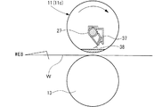
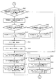
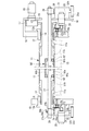
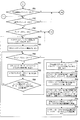
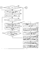
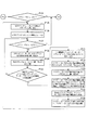
図1は本発明の実施例1を示すロータリー・スクリーン印刷機におけるロータリー・スクリーン印刷部の概略構成断面図、図2は図1の右側面図、図3は図1の左側面図、図4(a)及び図4(b)は作用状態図、図5(a)及び図5(b)は制御装置の制御ブロック図、図6(a)乃至図6(d)は制御装置の動作フロー図、図7(a)乃至図7(d)は制御装置の動作フロー図、図8は制御装置の動作フロー図、図9(a)乃至図9(d)は制御装置の動作フロー図、図10(a)乃至図10(d)は制御装置の動作フロー図、図11(a)乃至図11(e)は制御装置の動作フロー図、図12(a)乃至図12(d)は制御装置の動作フロー図である。
1 is a schematic sectional view of a rotary screen printing unit in a rotary screen printing
図1に示すように、ロータリー・スクリーン印刷機(輪転式孔版印刷機)におけるロータリー・スクリーン印刷部においては、左,右両フレーム10間にロータリー・スクリーン胴(孔版胴)11が偏心軸受12を介して圧胴13に対し着脱可能に支持される。尚、左,右両偏心軸受12は、左,右両フレーム10に回動自在でかつ左右方向(軸方向)に摺動自在に支持される。
As shown in FIG. 1, in a rotary screen printing unit in a rotary screen printing machine (rotary stencil printing machine), a rotary screen cylinder (stencil cylinder) 11 has an
前記ロータリー・スクリーン胴11は、左,右両筒状端部材11a間にそれぞれ中間部材11bを介して円筒状のスクリーン版(孔版)11cが支持されてなると共に、左,右両筒状端部材11aの小径部において、偏心軸受12に対しベアリング14により回転可能に支持される。
The
前記右方筒状端部材11aの小径部には端部に位置して歯車15が固着され、この歯車15には、モータ16の出力軸上に固着された歯車17が噛合する。前記モータ16は右方フレーム10に結合されたサブフレーム18に取り付けられる。
A
従って、前記ロータリー・スクリーン胴11は、前記モータ16により前述した歯車機構を介して回転駆動されると共に天地見当合せが可能になっている。
Therefore, the
前記左,右両偏心軸受12にはリンク19の一端がそれぞれピン結合され、これらのリンク19の他端にレバー20の先端がそれぞれピン結合される。前記左,右両レバー20の基端部は、左,右両フレーム10間に回動可能に架設された回転軸21の左,右両端部にそれぞれ固着される。そして、左方レバー20にはアクチュエータ22の先端がピン結合される。
One end of a
従って、前記アクチュエータ22により前述したリンク機構を介して偏心軸受12が回動されることで、ロータリー・スクリーン胴11は偏心回転され、圧胴13に対し着脱可能となる(図4の(a)及び図4の(b)参照)。
Accordingly, when the
前記左,右両偏心軸受12のフランジ部12aに形成した長孔には、ボルト23の頭部23aが回転可能でかつ長孔の長径方向に移動可能ではあるが軸方向には移動不能に嵌合される一方、ボルト23のねじ部23bがフレーム10のねじ孔に螺合している。前記左,右両ボルト23の頭部23aに歯車24aがそれぞれ固着され、これらの歯車24aには、モータ25の出力軸上に固着された歯車24bがそれぞれ噛合する。前記左,右両モータ25は左,右両フレーム10に結合された支持ブラケット26にそれぞれ取り付けられる。
In the long hole formed in the
従って、左,右両偏心軸受12は、前記モータ25により前述した歯車機構と送りねじ機構を介して左右方向(軸方向)に摺動され、スクリーン版11cのテンション調整とロータリー・スクリーン胴取外し時の軸受移動が可能となる。
Accordingly, the left and right
前記ロータリー・スクリーン胴11内には、図2及び図3にも示すように、右端閉塞のパイプ状の支持軸27が貫挿され、その右端(第1の端部)側はサブフレーム(第1のフレーム)18の外側方に位置する受け部材(第1の受け部材)28の嵌合孔28a内に回動かつ左右方向(軸方向)の移動(スライド)が可能に嵌合支持される一方、左端(第2の端部)側は左方フレーム(第2のフレーム)10の外側方に位置する受け部材(第2の受け部材)29により回動かつ左右方向(軸方向)の移動(スライド)が不能に嵌合支持される。
As shown in FIGS. 2 and 3, a pipe-
即ち、支持軸27の左端側は、左右二カ所の段付部27a,27bにて左右方向(軸方向)の移動(スライド)が阻止される一方、受け部材29の、溝底部がテーパ状に形成された嵌合溝29a内に収容された状態で押え板30aにより上方から押えられることで回動が阻止されるようになっている。
That is, on the left end side of the
前記押え板30aは、支点ピン31を中心にして水平回転することで嵌合溝29aを開閉可能になっており、同嵌合溝29aを閉塞した状態で固定レバー30bが押え板30aと受け部材29とにねじ込まれることにより閉塞状態が保持されるようになっている。
The
前記左,右両受け部材28,29は、フレーム10とサブフレーム18に付設された支持ケース31にボールねじ32を介して上下動可能に支持される。具体的には、ボールねじ32のナット部材32aが支持ケース31内に固着され、このナット部材32aに螺合するねじ部材32bが支持ケース31内を上下に貫通する。尚、ねじ部材32bの非ねじ形成軸部は軸受33を介して支持ケース31内に回動自在に支持される。
The left and right receiving
そして、前記ねじ部材32bの上端部は、当該ねじ部材32bの回転と支持軸27の後述する位置調整時における同支持軸27の傾きを許容し得るように球面軸受34を介して受け部材28,29の係合穴28b,29bに係合されている。一方、ねじ部材32bの下端部には歯車35aが固着され、この歯車35aには、モータ36A,36Bの出力軸上に固着された歯車35bが噛合する。前記左側のモータ36Aはフレーム10の外側面に、また右側のモータ36Bはサブフレーム18の外側面にそれぞれ取り付けられる。
The upper end portion of the
尚、図1中39は、支持軸27の無い時の受け部材28,29の位置決めと支持軸27の前後方向の位置決めのための廻り止めピンである。
In FIG. 1,
また、支持軸27には、図4(a)及び図4(b)に示すように、ホルダ37を介してゴム製のスキージ(インキ刷り移し部材)38が支持され、このスキージ38の先端がスクリーン版11cの内周面に摺接することで、支持軸27内を通ってスクリーン版11c内に供給されたインキがスクリーン版11cの孔を介してウェブW(被印刷物)の印刷面に刷り移される。
Further, as shown in FIGS. 4A and 4B, a rubber squeegee (ink transfer member) 38 is supported on the
そして、本実施例では、前記モータ36A,36Bが後述する制御装置(制御手段)40により各々独立して駆動制御され、前述したスキージ38のスクリーン版11cの内周面に対する着脱及び着位置調整が自動で行われるようになっている。
In the present embodiment, the
加えて、制御装置40は、前記スキージ38のスクリーン版11cの内周面に対する着脱の為の原点位置を調整し、その際の脱位置との相対位置を一定に制御する。また、制御装置40は、前記原点位置と着位置の相対位置をオペレータによる着位置調整量に応じて可変制御する。また、制御装置40は、前記スキージ38のスクリーン版11cの内周面に対する着脱の為の原点位置を調整した後の前記スキージ38のスクリーン版11cの内周面に着した状態のロータリー・スクリーン胴11(輪転式孔版印刷機)の総回転数を計測し、その計測したロータリー・スクリーン胴11の総回転数に応じて前記スキージ38のスクリーン版11cの内周面に対する着位置を調整するようにもなっている。
In addition, the
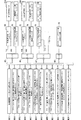
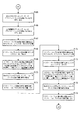
即ち、前記制御装置40は、図5(a)及び図5(b)に示すように、CPU41とRAM42とROM43と各入出力装置44〜48とが共にBUS線53で接続されてなる。また、このBUS線53には、スキージの左側の現在位置検出用カウンタのカウント値記憶用メモリM1,スキージの左側の原点位置(カウンタのカウント値)記憶用メモリM2,左側のカウント値差記憶用メモリM3,スキージの左側の現在位置記憶用メモリM4が接続される。
That is, as shown in FIGS. 5A and 5B, the
更にBUS線53には、スキージの右側の現在位置検出用カウンタのカウント値記憶用メモリM5,スキージの右側の原点位置(カウンタのカウント値)記憶用メモリM6,右側のカウント値差記憶用メモリM7,スキージの右側の現在位置記憶用メモリM8,目標とするスキージの左側位置検出用カウンタのカウント値記憶用メモリM9,目標とするスキージの右側位置検出用カウンタのカウント値記憶用メモリM10,カウント値S記憶用メモリM11,左側調整用モータ回転方向記憶用メモリM12,右側調整用モータ回転方向記憶用メモリM13が接続される。
Further, the
更にBUS線53には、スキージの左側の原点位置−脱位置間の距離(カウンタのカウント値)記憶用メモリM14,スキージの左側の脱位置(カウンタのカウント値)記憶用メモリM15,スキージの右側の原点位置−脱位置間の距離(カウンタのカウント値)記憶用メモリM16,スキージの右側の脱位置(カウンタのカウント値)記憶用メモリM17,スキージ着時の総回転数−スキージ位置補正量(カウンタのカウント値)変換テーブル記憶用メモリM18,スキージ着時の総回転数カウント用カウンタのカウント値記憶用メモリM19が接続される。
Further, the
更にBUS線53には、スキージ位置補正量(カウンタのカウント量)記憶用メモリM20,スキージの左側の原点位置−印刷位置間の距離(カウンタのカウント値)記憶用メモリM21,スキージの左側の印刷位置(カウンタのカウント値)記憶用メモリM22,スキージの右側の原点位置−印刷位置間の距離(カウンタのカウント値)記憶用メモリM23,スキージの右側の印刷位置(カウンタのカウント値)記憶用メモリM24が接続される。
Further, on the
入出力装置44には、原点復帰スイッチ54,左側調整選択スイッチ55,右側調整選択スイッチ56,両側調整選択スイッチ57,調整完了スイッチ58,アップ・ボタン59,ダウン・ボタン60,原点調整完了スイッチ61,スキージ着脱自動制御スイッチ62,スキージの左側の現在位置表示器63,スキージの右側の現在位置表示器64,キーボード等の入力装置65,CRTやディスプレイ等の表示器66,プリンタやフロッピーディスク(登録商標)ドライブ等の出力装置67が接続される。
The input /
入出力装置45には、左側調整用モータ・ドライバ68を介して左側調整用モータ36Aが接続されると共に、スキージの左側の現在位置検出用カウンタ70を介してモータ36Aに駆動連結された左側調整用モータ用ロータリ・エンコーダ71が接続される。
A
入出力装置46には、右側調整用モータ・ドライバ72を介して右側調整用モータ36Bが接続されると共に、スキージの右側の現在位置検出用カウンタ74を介してモータ36Bに駆動連結された右側調整用モータ用ロータリ・エンコーダ75が接続される。
A
入出力装置47には、スキージ着時の総回転数カウント用カウンタ76を介してロータリー・スクリーン胴の1回転検出用センサ77が接続される。また、入出力装置48には、ロータリー・スクリーン胴の胴入れ回路78が接続される。尚、ロータリー・スクリーン胴の1回転検出用センサ77は、ロータリー・スクリーン胴が1回転する毎に1パルス出力するようにロータリー・スクリーン印刷機の回転部分に設けられ、よって、スキージ着時の総回転数カウント用カウンタ74は、動作状態時のロータリー・スクリーン胴の回転数をカウントするようになっている。
A
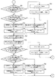
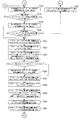
このような制御装置40の制御動作を、図6(a)乃至図6(d),図7(a)乃至図7(d),図8,図9(a)乃至図9(d),図10(a)乃至図10(d),図11(a)乃至図11(e),図12(a)乃至図12(d)の動作フロー図にしたがって詳述する。
The control operation of such a
先ず、ステップP1でスキージの左側の現在位置検出用カウンタ70よりカウント値を読込み、メモリM1に記憶した後、ステップP2でスキージの左側の原点位置(カウンタのカウント値)をメモリM2から読込む。次いで、ステップP3でスキージの左側の現在位置検出用カウンタ70のカウント値よりスキージの左側の原点位置(カウンタのカウント値)を減算し、左側のカウント値差を演算してメモリM3に記憶する。
First, in step P1, the count value is read from the current
次に、ステップP4で左側のカウント値差よりスキージの左側の現在位置を演算してメモリM4に記憶した後、ステップP5でスキージの左側の現在位置表示器63へスキージの左側の現在位置を出力する。
Next, in step P4, the current position on the left side of the squeegee is calculated from the left count value difference and stored in the memory M4. Then, in step P5, the current position on the left side of the squeegee is output to the
次に、ステップP6でスキージの右側の現在位置検出用カウンタ74よりカウント値を読込み、メモリM5に記憶した後、ステップP7でスキージの右側の原点位置(カウンタのカウント値)をメモリM6から読込む。次いで、ステップP8でスキージの右側の現在位置検出用カウンタ74のカウント値よりスキージの右側の原点位置(カウンタのカウント値)を減算し、右側のカウント値差を演算してメモリM7に記憶する。
Next, in step P6, the count value is read from the current
次に、ステップP9で右側のカウント値差よりスキージの右側の現在位置を演算してメモリM8に記憶した後、ステップP10でスキージの右側の現在位置表示器64へスキージの右側の現在位置を出力する。
Next, in step P9, the current position on the right side of the squeegee is calculated from the count value difference on the right side and stored in the memory M8. In step P10, the current position on the right side of the squeegee is output to the
次に、ステップP11で原点復帰スイッチ54がONか否かを判断し、可であればステップP12でスキージの左側の原点位置(カウンタのカウント値)をメモリM2から読込む一方、否であれば後述するステップP69に移行する。
Next, in step P11, it is determined whether the
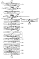
次に、ステップP13でスキージの左側の原点位置(カウンタのカウント値)を目標とするスキージの左側位置検出用カウンタのカウント値記憶用メモリM9に上書きした後、ステップP14でスキージの右側の原点位置(カウンタのカウント値)をメモリM6から読込む。 Next, in step P13, the origin position on the left side of the squeegee (count value of the counter) is overwritten on the count value storage memory M9 of the counter for detecting the left position of the squeegee, and in step P14, the origin position on the right side of the squeegee (Count value of counter) is read from the memory M6.
次に、ステップP15でスキージの右側の原点位置(カウンタのカウント値)を目標とするスキージの右側位置検出用カウンタのカウント値記憶用メモリM10に上書きした後、ステップP16でメモリM11のカウント値Sに0を上書きする。 Next, in step P15, the origin position on the right side of the squeegee (count value of the counter) is overwritten on the count value storage memory M10 of the right position detection counter for the squeegee, and then in step P16, the count value S of the memory M11 is stored. Overwrite with 0.
次に、ステップP17で左側調整用モータ回転方向記憶用メモリM12に0を上書きした後、ステップP18で右側調整用モータ回転方向記憶用メモリM13に0を上書きする。 Next, after 0 is overwritten in the left adjustment motor rotation direction storage memory M12 in step P17, 0 is overwritten in the right adjustment motor rotation direction storage memory M13 in step P18.
次に、ステップP19でスキージの左側の現在位置検出用カウンタ70よりカウント値を読込み、メモリM4に記憶した後、ステップP20で目標とするスキージの左側位置検出用カウンタのカウント値をメモリM9から読込む。
Next, in step P19, the count value is read from the current
次に、ステップP21でスキージの左側の現在位置検出用カウンタのカウント値=目標とするスキージの左側位置検出用カウンタのカウント値か否かを判断し、否であればステップP22でスキージの左側の現在位置検出用カウンタのカウント値<目標とするスキージの左側位置検出用カウンタのカウント値か否かを判断する一方、可であればステップP23でカウント値SをメモリM11から読込んだ後、ステップP24でメモリM11のカウント値Sに1を加算し、上書きして後述するステップP27に移行する。 Next, in step P21, it is determined whether or not the count value of the current position detection counter on the left side of the squeegee = the count value of the left position detection counter of the target squeegee. While it is determined whether the count value of the current position detection counter <the count value of the left position detection counter of the target squeegee, if yes, the count value S is read from the memory M11 in step P23, and then step In P24, 1 is added to the count value S of the memory M11, overwriting, and the process proceeds to Step P27 described later.
次に、前記ステップP22で可であれば、ステップP25で左側調整用モータ回転方向記憶用メモリM12に1を上書きした後、ステップP26で左側調整用モータ・ドライバ68に正転指令を出力してステップP27に移行する。
If yes in step P22, 1 is overwritten in the left adjustment motor rotation direction storage memory M12 in step P25, and then a normal rotation command is output to the left
一方、前記ステップP22で否であれば、ステップP28で左側調整用モータ回転方向記憶用メモリM12に2を上書きした後、ステップP29で左側調整用モータ・ドライバ68に逆転指令を出力してステップP27に移行する。
On the other hand, if NO in step P22, 2 is overwritten in the left adjustment motor rotation direction storage memory M12 in step P28, and then a reverse rotation command is output to the left
次に、前記ステップP27でスキージの右側の現在位置検出用カウンタ74よりカウント値を読込み、メモリM8に記憶した後、ステップP30で目標とするスキージの右側位置検出用カウンタのカウント値をメモリM10から読込む。
Next, in step P27, the count value is read from the current
次に、ステップP31でスキージの右側の現在位置検出用カウンタのカウント値=目標とするスキージの右側位置検出用カウンタのカウント値か否かを判断し、否であればステップP32でスキージの右側の現在位置検出用カウンタのカウント値<目標とするスキージの右側位置検出用カウンタのカウント値か否かを判断する一方、可であればステップP33でカウント値SをメモリM11から読込んだ後、ステップP34でメモリM11のカウント値Sに1を加算し、上書きして後述するステップP37に移行する。 Next, in step P31, it is determined whether or not the count value of the current position detection counter on the right side of the squeegee = the count value of the right position detection counter of the target squeegee. While it is determined whether the count value of the current position detection counter <the count value of the right position detection counter of the target squeegee, if yes, the count value S is read from the memory M11 in step P33, and then step In P34, 1 is added to the count value S of the memory M11, overwriting, and the process proceeds to Step P37 described later.
次に、前記ステップP32で可であれば、ステップP35で右側調整用モータ回転方向記憶用メモリM13に1を上書きした後、ステップP36で右側調整用モータ・ドライバ72に正転指令を出力してステップP37に移行する。
Next, if yes in step P32, after overwriting 1 in the right-hand adjustment motor rotation direction storage memory M13 in step P35, a forward rotation command is output to the right-hand
一方、前記ステップP32で否であれば、ステップP38で右側調整用モータ回転方向記憶用メモリM13に2を上書きした後、ステップP39で右側調整用モータ・ドライバ72に逆転指令を出力してステップP37に移行する。
On the other hand, if the answer is NO in step P32, 2 is overwritten in the right-hand adjustment motor rotation direction storage memory M13 in step P38, and then a reverse rotation command is output to the right-hand
次に、前記ステップP37でカウント値SをメモリM11から読込んだ後、ステップP40でカウント値S=2か否かを判断する。 Next, after reading the count value S from the memory M11 in step P37, it is determined in step P40 whether the count value S = 2.
次に、前記ステップP40で可であればステップP1に戻る一方、否であればステップP41でスキージの左側の現在位置検出用カウンタ70よりカウント値を読込み、メモリM1に記憶する。
If yes in step P40, the process returns to step P1. If no, the count value is read from the current
次に、ステップP42でスキージの左側の原点位置(カウンタのカウント値)をメモリM2から読込んだ後、ステップP43でスキージの左側の現在位置検出用カウンタのカウント値よりスキージの左側の原点位置(カウンタのカウント値)を減算し、左側のカウンタ値差を演算してメモリM3に記憶する。 Next, after the origin position (counter value of the counter) on the left side of the squeegee is read from the memory M2 in step P42, the origin position on the left side of the squeegee (from the count value of the current position detection counter on the left side of the squeegee) is read in step P43. (Count value of the counter) is subtracted, and the counter value difference on the left side is calculated and stored in the memory M3.
次に、ステップP44で左側のカウント値差よりスキージの左側の現在位置を演算してメモリM4に記憶した後、ステップP45でスキージの左側の現在位置表示器63へスキージの左側の現在位置を出力する。
Next, in step P44, the current position on the left side of the squeegee is calculated from the left count value difference and stored in the memory M4. In step P45, the current position on the left side of the squeegee is output to the
次に、ステップP46で目標とするスキージの左側位置検出用カウンタのカウント値をメモリM9から読込んだ後、ステップP47でスキージの左側の現在位置検出用カウンタのカウント値=目標とするスキージの左側位置検出用カウンタのカウント値か否かを判断する。 Next, after the count value of the counter for detecting the left position of the target squeegee is read from the memory M9 in step P46, the count value of the counter for detecting the current position of the left side of the squeegee = the left side of the target squeegee in step P47. It is determined whether or not the count value of the position detection counter.
次に、前記ステップ47で可であればステップP48で左側調整用モータ回転方向記憶用メモリM12の値を読込む一方、否であれば後述するステップP55に移行する。
Next, if yes in
次に、ステップP49で左側調整用モータ回転方向記憶用メモリの値=1か否かを判断し、可であればステップP50で左側調整用モータ・ドライバ68への正転指令出力を停止してステップP51に移行する一方、否であればステップP52で左側調整用モータ回転方向記憶用メモリの値=2か否かを判断する。
Next, in step P49, it is determined whether or not the value of the left adjustment motor rotation direction storage memory = 1. If yes, the forward rotation command output to the left
次に、前記ステップP52で可であればステップP53で左側調整用モータ・ドライバ68への逆転指令出力を停止してステップP51に移行する一方、否であれば後述するステップP55に移行する。
Next, if yes in step P52, the reverse rotation command output to the left
次に、前記ステップP51でカウント値SをメモリM11から読込んだ後、ステップP54でメモリM11のカウント値Sに1を加算し、上書きする。次いで、前記ステップP55でスキージの右側の現在位置検出用カウンタ74よりカウント値を読込み、メモリM5に記憶する。
Next, after reading the count value S from the memory M11 in step P51, 1 is added to the count value S in the memory M11 and overwritten in step P54. In step P55, the count value is read from the current
次に、ステップP56でスキージの右側の原点位置(カウンタのカウント値)をメモリM6から読込んだ後、ステップP57でスキージの右側の現在位置検出用カウンタ74のカウント値よりスキージの右側の原点位置(カウンタのカウント値)を減算し、右側のカウント値差を演算してメモリM7に記憶する。
Next, after the origin position (counter count value) on the right side of the squeegee is read from the memory M6 in step P56, the origin position on the right side of the squeegee is determined from the count value of the current
次に、ステップP58で右側のカウント値差よりスキージの右側の現在位置を演算してメモリM8に記憶した後、ステップP59でスキージの右側の現在位置表示器64へスキージの右側の現在位置を出力する。
Next, after calculating the current position on the right side of the squeegee from the count value difference on the right side in step P58 and storing it in the memory M8, the current position on the right side of the squeegee is output to the
次に、ステップP60で目標とするスキージの右側位置検出用カウンタのカウント値をメモリM10から読込んだ後、ステップP61でスキージの右側の現在位置検出用カウンタのカウント値=目標とするスキージの右側位置検出用カウンタのカウント値か否かを判断する。 Next, after the count value of the right position detection counter for the squeegee is read from the memory M10 in step P60, the count value of the current position detection counter on the right side of the squeegee is equal to the right side of the target squeegee in step P61. It is determined whether or not the count value of the position detection counter.
次に、前記ステップP61で可であればステップP62で右側調整用モータ回転方向記憶用メモリM13の値を読込む一方、否であればステップP37に戻る。 Next, if yes in step P61, the value in the right adjustment motor rotation direction storage memory M13 is read in step P62, and if no, the process returns to step P37.
次に、ステップP63で右側調整用モータ回転方向記憶用メモリの値=1か否かを判断し、可であればステップP64で右側調整用モータ・ドライバ72への正転指令出力を停止する一方、否であればステップP67で右側調整用モータ回転方向記憶用メモリの値=2か否かを判断する。
Next, in step P63, it is determined whether or not the value of the right adjustment motor rotation direction storage memory = 1. If yes, the forward rotation command output to the right
次に、前記ステップP67で可であればステップP68で右側調整用モータ・ドライバ72への逆転指令出力を停止してステップP65に移行する一方、否であれば即ステップP37に戻る。
If yes in step P67, the reverse rotation command output to the right
次に、ステップP65でカウント値SをメモリM11から読込んだ後、ステップP66でメモリM11のカウント値Sに1を加算し、上書きした後、ステップP37に戻る。以上の動作フローによって、スキージ38を交換するため、支持軸27の左右両側を原点復帰スイッチ54が押された時点の原点位置に戻す。
Next, after reading the count value S from the memory M11 in step P65, 1 is added to the count value S in the memory M11 in step P66, and the process returns to step P37. With the above operation flow, in order to replace the
次に、前述したステップP11から移行したステップ69で左側調整選択スイッチ55がONか否かを判断し、可であればステップP70で調整完了スイッチ58がONか否かを判断する一方、否であれば後述するステップP89に移行する。
Next, it is determined whether or not the left side
次に、前記ステップP70で可であれば後述するステップP89に移行する一方、否であればステップP71でアップ・ボタン59がONか否かを判断する。次いで、このステップP71で可であればステップP72で左側調整用モータ・ドライバ68に正転指令を出力する一方、否であれば後述するステップP80に移行する。
Next, if yes in step P70, the process proceeds to step P89 described later. If no, it is determined in step P71 whether the
次に、ステップP73でスキージの左側の現在位置検出用カウンタ70よりカウント値を読込み、メモリM1に記憶した後、ステップP74でスキージの左側の原点位置(カウンタのカウント値)をメモリM2から読込む。
Next, in step P73, the count value is read from the current
次に、ステップP75でスキージの左側の現在位置検出用カウンタ70のカウント値よりスキージの左側の原点位置(カウンタのカウント値)を減算し、左側のカウント値差を演算してメモリM3に記憶した後、ステップP76で左側のカウント値差よりスキージの左側の現在位置を演算してメモリM4に記憶する。
Next, at step P75, the origin position (count value of the counter) on the left side of the squeegee is subtracted from the count value of the current
次に、ステップP77でスキージの左側の現在位置表示器63へスキージの左側の現在位置を出力した後、ステップP78でアップ・ボタン59がOFFか否かを判断する。このステップ78で可であればステップP79で左側調整用モータ・ドライバ68への正転指令出力を停止する一方、否であればステップP73に戻る。
Next, after outputting the current position on the left side of the squeegee to the
次に、ステップP80でダウン・ボタン60がONか否かを判断し、可であればステップP81で左側調整用モータ・ドライバ68に逆転指令を出力する一方、否であればステップP70に戻る。
Next, in step P80, it is determined whether or not the
次に、ステップP82でスキージの左側の現在位置検出用カウンタ70よりカウント値を読込み、メモリM1に記憶した後、ステップP83でスキージの左側の原点位置(カウンタのカウント値)をメモリM2から読込む。
Next, in step P82, the count value is read from the current
次に、ステップP84でスキージの左側の現在位置検出用カウンタ70のカウント値よりスキージの左側の原点位置(カウンタのカウント値)を減算し、左側のカウント値差を演算してメモリM3に記憶した後、ステップP85で左側のカウント値差よりスキージの左側の現在位置を演算してメモリM4に記憶する。
Next, in step P84, the origin position on the left side of the squeegee (count value of the counter) is subtracted from the count value of the current
次に、ステップP86でスキージの左側の現在位置表示器63へスキージの左側の現在位置を出力した後、ステップP87でダウン・ボタン60がOFFか否かを判断する。次いで、このステップP87で可であればステップP88で左側調整用モータ・ドライバ68への逆転指令出力を停止してステップP70に戻る一方、否であればステップP82に戻る。
Next, after outputting the current position on the left side of the squeegee to the
次に、ステップP89で右側調整選択スイッチ56がONか否かを判断し、可であればステップP90で調整完了スイッチ58がONか否かを判断する一方、否であれば後述するステップP109に移行する。
Next, in step P89, it is determined whether or not the right
次に、前記ステップP90で可であれば後述するステップP109に移行する一方、否であればステップP91でアップ・ボタン59がONか否かを判断する。次いで、このステップP91で可であればステップP92で右側調整用モータ・ドライバ72に正転指令を出力する一方、否であれば後述するステップP100に移行する。
Next, if yes in step P90, the process proceeds to step P109, which will be described later. If no, it is determined in step P91 whether the
次に、ステップP93でスキージの右側の現在位置検出用カウンタ74よりカウント値を読込み、メモリM5に記憶した後、ステップP94でスキージの右側の原点位置(カウンタのカウント値)をメモリM6から読込む。
Next, in step P93, the count value is read from the current
次に、ステップP95でスキージの右側の現在位置検出用カウンタ74のカウント値よりスキージの右側の原点位置(カウンタのカウント値)を減算し、右側のカウント値差を演算してメモリM7に記憶した後、ステップP96で右側のカウント値差よりスキージの右側の現在位置を演算してメモリM8に記憶する。
Next, in step P95, the origin position (count value of the counter) on the right side of the squeegee is subtracted from the count value of the current
次に、ステップP97でスキージの右側の現在位置表示器64へスキージの右側の現在位置を出力した後、ステップP98でアップ・ボタン59がOFFか否かを判断する。次いで、このステップ98で可であればステップP99で右側調整用モータ・ドライバ72への正転指令出力を停止する一方、否であればステップP93に戻る。
Next, after outputting the current position on the right side of the squeegee to the
次に、ステップP100でダウン・ボタン60がONか否かを判断し、可であればステップP101で右側調整用モータ・ドライバ72に逆転指令を出力する一方、否であればステップP90に戻る。
Next, it is determined in step P100 whether or not the
次に、ステップP102でスキージの右側の現在位置検出用カウンタ74よりカウント値を読込み、メモリM5に記憶した後、ステップP103でスキージの右側の原点位置(カウンタのカウント値)をメモリM6から読込む。
Next, in step P102, the count value is read from the current
次に、ステップP104でスキージの右側の現在位置検出用カウンタ74のカウント値よりスキージの右側の原点位置(カウンタのカウント値)を減算し、右側のカウント値差を演算してメモリM7に記憶した後、ステップP105で右側のカウント値差よりスキージの右側の現在位置を演算してメモリM8に記憶する。
Next, in step P104, the origin position on the right side of the squeegee (count value of the counter) is subtracted from the count value of the current
次に、ステップP106でスキージの右側の現在位置表示器64へスキージの右側の現在位置を出力した後、ステップP107でダウン・ボタン60がOFFか否かを判断する。次いで、このステップP107で可であればステップP108で右側調整用モータ・ドライバ72への逆転指令出力を停止してステップP90に戻る一方、否であればステップP102に戻る。
Next, after outputting the current position on the right side of the squeegee to the
次に、ステップP109で両側調整選択スイッチ57がONか否かを判断し、可であればステップP110で調整完了スイッチ58がONか否かを判断する一方、否であれば後述するステップP143に移行する。
Next, in step P109, it is determined whether or not the double side
次に、前記ステップP110で可であれば後述するステップP143に移行する一方、否であればステップP111でアップ・ボタン59がONか否かを判断する。次いで、このステップP111で可であればステップP112で左側調整用モータ・ドライバ68に正転指令を出力する一方、否であれば後述するステップP127に移行する。
Next, if yes in step P110, the process proceeds to step P143, which will be described later. If no, it is determined in step P111 whether the
次に、ステップP113で右側調整用モータ・ドライバ72に正転指令を出力した後、ステップP114でスキージの左側の現在位置検出用カウンタ70よりカウント値を読込み、メモリM1に記憶する。
Next, after a forward rotation command is output to the right
次に、ステップP115でスキージの左側の原点位置(カウンタのカウント値)をメモリM2から読込んだ後、ステップP116でスキージの左側の現在位置検出用カウンタ70のカウント値よりスキージの左側の原点位置(カウンタのカウント値)を減算し、左側のカウント値差を演算してメモリM3に記憶する。
Next, in step P115, the origin position (counter count value) on the left side of the squeegee is read from the memory M2, and in step P116, the origin position on the left side of the squeegee is determined from the count value of the current
次に、ステップP117で左側のカウント値差よりスキージの左側の現在位置を演算してメモリM4に記憶した後、ステップP118でスキージの左側の現在位置表示器63へスキージの左側の現在位置を出力する。
Next, in step P117, the current position on the left side of the squeegee is calculated from the count value difference on the left side and stored in the memory M4. In step P118, the current position on the left side of the squeegee is output to the
次に、ステップP119でスキージの右側の現在位置検出用カウンタ74よりカウント値を読込み、メモリM5に記憶した後、ステップP120でスキージの右側の原点位置(カウンタのカウント値)をメモリM6から読込む。
Next, in step P119, the count value is read from the current
次に、ステップP121でスキージの右側の現在位置検出用カウンタ74のカウント値よりスキージの右側の原点位置(カウンタのカウント値)を減算し、右側のカウント値差を演算してメモリM7に記憶した後、ステップP122で右側のカウント値差よりスキージの右側の現在位置を演算してメモリM8に記憶する。
Next, in step P121, the origin position on the right side of the squeegee (count value of the counter) is subtracted from the count value of the current
次に、ステップP123でスキージの右側の現在位置表示器64へスキージの右側の現在位置を出力した後、ステップP124でアップ・ボタン59がOFFか否かを判断する。次いで、このステップP124で可であればステップP125で左側調整用モータ・ドライバ68への正転指令出力を停止する一方、否であればステップP114に戻る。
Next, after outputting the current position on the right side of the squeegee to the
次に、ステップP126で右側調整用モータ・ドライバ72への正転指令出力を停止した後、ステップP127でダウン・ボタン60がONか否かを判断する。次いで、このステップP127で可であればステップP128で左側調整用モータ・ドライバ68に逆転指令を出力する一方、否であればステップP110に戻る。
Next, after stopping the normal rotation command output to the right
次に、ステップP129で右側調整用モータ・ドライバ72に逆転指令を出力した後、ステップP130でスキージの左側の現在位置検出用カウンタ70よりカウント値を読込み、メモリM1に記憶する。
Next, after a reverse rotation command is output to the right
次に、ステップP131でスキージの左側の原点位置(カウンタのカウント値)をメモリM2から読込んだ後、ステップP132でスキージの左側の現在位置検出用カウンタ70のカウント値よりスキージの左側の原点位置(カウンタのカウント値)を減算し、左側のカウント値差を演算してメモリM3に記憶する。
Next, after the origin position (counter value of the counter) on the left side of the squeegee is read from the memory M2 in step P131, the origin position on the left side of the squeegee is determined from the count value of the current
次に、ステップP133で左側のカウント値差よりスキージの左側の現在位置を演算してメモリM4に記憶した後、ステップP134でスキージの左側の現在位置表示器63へスキージの左側の現在位置を出力する。
Next, in step P133, the current position on the left side of the squeegee is calculated from the left count value difference and stored in the memory M4. In step P134, the current position on the left side of the squeegee is output to the
次に、ステップP135でスキージの右側の現在位置検出用カウンタ74よりカウント値を読込み、メモリM5に記憶した後、ステップP136でスキージの右側の原点位置(カウンタのカウント値)をメモリM6から読込む。
Next, in step P135, the count value is read from the current
次に、ステップP137でスキージの右側の現在位置検出用カウンタ74のカウント値よりスキージの右側の原点位置(カウンタのカウント値)を減算し、右側のカウント値差を演算してメモリM7に記憶した後、ステップP138で右側のカウント値差よりスキージの右側の現在位置を演算してメモリM8に記憶する。
Next, in step P137, the origin position (count value of the counter) on the right side of the squeegee is subtracted from the count value of the current
次に、ステップP139でスキージの右側の現在位置表示器64へスキージの右側の現在位置を出力した後、ステップP140でダウン・ボタン60がOFFか否かを判断する。次いで、このステップP140で可であればステップP141で左側調整用モータ・ドライバ68への逆転指令出力を停止する一方、否であればステップP130に戻る。以上の動作フローによって、操作者の手動操作によるスキージ38交換後の支持軸27の原点位置調整、言い換えれば、スキージ38の平行出しが行われる。
Next, after outputting the current position on the right side of the squeegee to the
次に、ステップP142で右側調整用モータ・ドライバ72への逆転指令出力を停止した後、ステップP110に戻る。
Next, after stopping the reverse rotation command output to the right
次に、前述したステップP109及びステップP110から移行したステップP143で原点調整完了スイッチ61がONか否かを判断し、可であればステップP144でスキージの左側の現在位置検出用カウンタ70よりカウント値を読込み、メモリM1に記憶する一方、否であれば後述するステップP152に移行する。
Next, it is determined whether or not the origin
次に、ステップP145でスキージの左側の現在位置検出用カウンタ70のカウント値をスキージの左側の原点位置(カウンタのカウント値)記憶用メモリM2に上書きした後、ステップP146でスキージの左側の現在位置表示器63へ0を出力する。
Next, after the count value of the current
次に、ステップP147でスキージの右側の現在位置検出用カウンタ74よりカウント値を読込み、メモリM5に記憶した後、ステップP148でスキージの右側の現在位置検出用カウンタ74のカウント値をスキージの右側の原点位置(カウンタのカウント値)記憶用メモリM6に上書きする。
Next, in step P147, the count value is read from the current
次に、ステップP149でスキージの右側の現在位置表示器64へ0を出力した後、ステップP150でスキージ着時の総回転数カウント用カウンタ76へリセット信号を出力する。次いで、ステップP151でスキージ着時の総回転数カウント用カウンタ76へのリセット信号出力を停止してステップP11に戻る。以上の動作フローによって、操作者が手動操作によって調整したスキージ38交換後の支持軸27の原点位置を、以後の新たな原点位置として記憶すると共に、スキージ着時の総回転数カウント用カウンタ76の状態を、初期状態にする(リセットする)。
Next, after outputting 0 to the
次に、前述したステップP143から移行したステップP152でスキージ着脱自動制御スイッチ62がONか否かを判断し、可であればステップP153でスキージ着脱自動制御スイッチ62がOFFか否かを判断する一方、否であればステップP11に戻る。
Next, it is determined whether or not the squeegee attachment / detachment
次に、前記ステップP153で可であれば後述するステップP367に移行する一方、否であればステップP154でロータリー・スクリーン胴の胴入れ回路78よりロータリー・スクリーン胴の胴入れ信号がONか否かを判断する。
Next, if yes in Step P153, the process proceeds to Step P367, which will be described later. If No, in Step P154, whether the rotary screen cylinder insertion signal is ON from the rotary screen
次に、前記154で可であれば後述するステップP215に移行する一方、否であればステップP155でスキージの左側の原点位置(カウンタのカウント値)をメモリM2から読込む。 Next, if yes in step 154, the process proceeds to step P215, which will be described later. If no, in step P155, the origin position (counter value) of the left side of the squeegee is read from the memory M2.
次に、ステップP156でスキージの左側の原点位置−脱位置間の距離(カウンタのカウント値)をメモリM14から読込んだ後、ステップP157でスキージの左側の原点位置(カウンタのカウント値)にスキージの左側の原点位置−脱位置間の距離(カウンタのカウント値)を加算し、スキージの左側の脱位置(カウンタのカウント値)を演算して、メモリM15に記憶する。 Next, in step P156, the distance (counter count value) between the origin position on the left side of the squeegee and the withdrawal position is read from the memory M14, and then in step P157, the origin position (counter count value) on the left side of the squeegee is set. The left-side origin position-displacement distance (counter count value) is added, and the left-side squeegee escape position (counter count value) is calculated and stored in the memory M15.
次に、ステップP158でスキージの左側の脱位置(カウンタのカウント値)を目標とするスキージの左側位置検出用カウンタのカウント値記憶用メモリM9に上書きした後、ステップP159でスキージの右側の原点位置(カウンタのカウント値)をメモリM6から読込む。 Next, in step P158, the left position of the squeegee (count value of the counter) is overwritten in the count value storage memory M9 of the counter for detecting the left position of the squeegee, and then in step P159, the origin position on the right side of the squeegee (Count value of counter) is read from the memory M6.
次に、ステップP160でスキージの右側の原点位置−脱位置間の距離(カウンタのカウント値)をメモリM16から読込んだ後、ステップP161でスキージの右側の原点位置(カウンタのカウント値)にスキージの右側の原点位置−脱位置間の距離(カウンタのカウント値)を加算し、スキージの右側の脱位置(カウンタのカウント値)を演算して、メモリM17に記憶する。 Next, in step P160, the distance between the origin position on the right side of the squeegee and the dislocation position (counter value of the counter) is read from the memory M16, and then in step P161, the origin position (counter value of the counter) on the right side of the squeegee is set. The distance between the origin position on the right side and the displacement position (count value of the counter) is added, and the displacement position (count value of the counter) on the right side of the squeegee is calculated and stored in the memory M17.
次に、ステップP162でスキージの右側の脱位置(カウンタのカウント値)を目標とするスキージの右側位置検出用カウンタのカウント値記憶用メモリM10に上書きした後、ステップP163でメモリM11のカウント値Sに0を上書きする。 Next, in step P162, the right position of the squeegee is overwritten on the count value storage memory M10 of the right squeegee position detection counter, and then in step P163, the count value S of the memory M11 is overwritten. Overwrite with 0.
次に、ステップP164で左側調整用モータ回転方向記憶用メモリM12に0を上書きした後、ステップP165で右側調整用モータ回転方向記憶用メモリM13に0を上書きする。 Next, after 0 is overwritten in the left adjustment motor rotation direction storage memory M12 in step P164, 0 is overwritten in the right adjustment motor rotation direction storage memory M13 in step P165.
次に、ステップP166でスキージの左側の現在位置検出用カウンタ70よりカウント値を読込み、メモリM1に記憶した後、ステップP167で目標とするスキージの左側位置検出用カウンタのカウント値をメモリM9から読込む。
Next, in step P166, the count value is read from the current
次に、ステップP168でスキージの左側の現在位置検出用カウンタのカウント値=目標とするスキージの左側位置検出用カウンタのカウント値か否かを判断し、否であればステップP169でスキージの左側の現在位置検出用カウンタのカウント値<目標とするスキージの左側位置検出用カウンタのカウント値か否かを判断する一方、可であればステップP170でカウント値SをメモリM11から読込む。 Next, in step P168, it is determined whether or not the count value of the current position detection counter on the left side of the squeegee = the count value of the left position detection counter of the target squeegee. While it is determined whether the count value of the current position detection counter <the count value of the left position detection counter of the target squeegee, if yes, the count value S is read from the memory M11 in step P170.
次に、ステップP171でメモリM11のカウント値Sに1を加算し、上書きした後、後述するステップP174に移行する。 Next, after adding 1 to the count value S of the memory M11 in step P171 and overwriting, the process proceeds to step P174 described later.
次に、前記ステップP169で可であればステップP172で左側調整用モータ回転方向記憶用メモリM12に1を上書きした後、ステップP173で左側調整用モータ・ドライバ68に正転指令を出力する。次いで、ステップP174でスキージの右側の現在位置検出用カウンタ74よりカウント値を読込み、メモリM5に記憶する。
If yes in step P169, 1 is overwritten in the left adjustment motor rotation direction storage memory M12 in step P172, and then a normal rotation command is output to the left
次に、前記ステップP169で否であればステップP175で左側調整用モータ回転方向記憶用メモリM12に2を上書きした後、ステップP176で左側調整用モータ・ドライバ68に逆転指令を出力してステップP174に移行する。
Next, if the result is NO in step P169, 2 is overwritten in the left adjustment motor rotation direction storage memory M12 in step P175, and then a reverse rotation command is output to the left
次に、ステップP177で目標とするスキージの右側位置検出用カウンタのカウント値をメモリM10から読込んだ後、ステップP178aでスキージの右側の現在位置検出用カウンタのカウント値=目標とするスキージの右側位置検出用カウンタのカウント値か否かを判断する。 Next, after reading the count value of the right position detection counter of the target squeegee from the memory M10 in step P177, the count value of the current position detection counter on the right side of the squeegee = the right side of the target squeegee in step P178a. It is determined whether or not the count value of the position detection counter.
次に、前記ステップP178aで否であればステップP179でスキージの右側の現在位置検出用カウンタのカウント値<目標とするスキージの右側位置検出用カウンタのカウント値か否かを判断する一方、可であればステップP178bでカウント値SをメモリM11から読込む。 If NO in step P178a, it is determined in step P179 whether the count value of the current position detection counter on the right side of the squeegee is smaller than the count value of the right position detection counter of the target squeegee. If there is, the count value S is read from the memory M11 in step P178b.
次に、ステップP178cでメモリM11のカウント値Sに1を加算し、上書きした後、後述するステップP182に移行する。 Next, in step P178c, 1 is added to the count value S of the memory M11, and after overwriting, the process proceeds to step P182 described later.
次に、ステップP179で可であればステップP180で右側調整用モータ回転方向記憶用メモリM13に1を上書きした後、ステップP181で右側調整用モータ・ドライバ72に正転指令を出力してステップP182に移行する。
If yes in step P179, 1 is overwritten in the right-hand adjustment motor rotation direction storage memory M13 in step P180, and then a normal rotation command is output to the right-hand
次に、前記ステップP179で否であればステップP183で右側調整用モータ回転方向記憶用メモリM13に2を上書きした後、ステップP184で右側調整用モータ・ドライバ72に逆転指令を出力してステップP182に移行する。
If NO in step P179, 2 is overwritten in the right-hand adjustment motor rotation direction storage memory M13 in step P183, and a reverse rotation command is output to the right-hand
次に、ステップP182でカウント値SをメモリM11から読込んだ後、ステップP185でカウント値S=2か否かを判断し、可であればステップP186でスキージ着時の総回転数カウント用カウンタ76へのイネーブル信号出力を停止してステップP153に戻る一方、否であればステップP187に移行する。 Next, after reading the count value S from the memory M11 in Step P182, it is determined whether or not the count value S = 2 in Step P185. If yes, the counter for counting the total number of revolutions when the squeegee is attached is determined in Step P186. The output of the enable signal to 76 is stopped and the process returns to Step P153. If not, the process proceeds to Step P187.
次に、ステップP187でスキージの左側の現在位置検出用カウンタ70よりカウント値を読込み、メモリM1に記憶した後、ステップP188でスキージの左側の原点位置(カウンタのカウント値)をメモリM2から読込む。次いで、ステップP189でスキージの左側の現在位置検出用カウンタ70のカウント値よりスキージの左側の原点位置(カウンタのカウント値)を減算し、左側のカウント値差を演算して、メモリM3に記憶する。
Next, in step P187, the count value is read from the current
次に、ステップP190で左側のカウント値差よりスキージの左側の現在位置を演算して、メモリM4に記憶した後、ステップP191でスキージの左側の現在位置表示器63へスキージの左側の現在位置を出力する。
Next, in step P190, the current position on the left side of the squeegee is calculated from the left count value difference and stored in the memory M4. Then, in step P191, the
次に、ステップP192で目標とするスキージの左側位置検出用カウンタのカウント値をメモリM9から読込んだ後、ステップP193でスキージの左側の現在位置検出用カウンタのカウント値=目標とするスキージの左側位置検出用カウンタのカウント値か否かを判断する。 Next, after the count value of the counter for detecting the left position of the target squeegee is read from the memory M9 in Step P192, the count value of the counter for detecting the current position on the left side of the squeegee is equal to the left side of the target squeegee in Step P193. It is determined whether or not the count value of the position detection counter.
次に、前記ステップP193で可であればステップP194で左側調整用モータ回転方向記憶用メモリM12の値を読込む一方、否であれば後述するステップP201に移行する。 Next, if yes in step P193, the value in the left adjustment motor rotation direction storage memory M12 is read in step P194, and if no, the process proceeds to later-described step P201.
次に、ステップP195で左側調整用モータ回転方向記憶用メモリの値=1か否かを判断し、可であればステップP196で左側調整用モータ・ドライバ68への正転指令出力を停止してステップP197に移行する一方、否であればステップP198で左側調整用モータ回転方向記憶用メモリの値=2か否かを判断する。
Next, in step P195, it is determined whether or not the value of the left adjustment motor rotation direction storage memory = 1. If yes, the forward rotation command output to the left
次に、前記ステップP198で可であればステップP199で左側調整用モータ・ドライバ68への逆転指令出力を停止してステップP197に移行する一方、否であれば後述するステップP201に移行する。
Next, if yes in Step P198, in Step P199, the reverse rotation command output to the left
次に、ステップP197でカウント値SをメモリM11から読込んだ後、ステップP200でメモリM11のカウント値Sに1を加算し、上書きする。 Next, after reading the count value S from the memory M11 in step P197, 1 is added to the count value S of the memory M11 and overwritten in step P200.
次に、ステップP201でスキージの右側の現在位置検出用カウンタ74よりカウント値を読込み、メモリM5に記憶した後、ステップP202でスキージの右側の原点位置(カウンタのカウント値)をメモリM6から読込む。次いで、ステップP203でスキージの右側の現在位置検出用カウンタ74のカウント値よりスキージの右側の原点位置(カウンタのカウント値)を減算し、右側のカウント値差を演算して、メモリM7に記憶する。
Next, in step P201, the count value is read from the current
次に、ステップP204で右側のカウント値差よりスキージの右側の現在位置を演算して、メモリM8に記憶した後、ステップP205でスキージの右側の現在位置表示器64へスキージの右側の現在位置を出力する。
Next, in Step P204, the current position on the right side of the squeegee is calculated from the right count value difference and stored in the memory M8. In Step P205, the current position on the right side of the squeegee is displayed on the
次に、ステップP206で目標とするスキージの右側位置検出用カウンタのカウント値をメモリM10から読込んだ後、ステップP207でスキージの右側の現在位置検出用カウンタのカウント値=目標とするスキージの右側位置検出用カウンタのカウント値か否かを判断する。 Next, after reading the count value of the right position detection counter of the target squeegee from the memory M10 in step P206, the count value of the current position detection counter on the right side of the squeegee = the right side of the target squeegee in step P207. It is determined whether or not the count value of the position detection counter.
次に、前記ステップP207で可であればステップP208で右側調整用モータ回転方向記憶用メモリM13の値を読込む一方、否であればステップP182に移行する。 Next, if yes in step P207, the value in the right adjustment motor rotation direction storage memory M13 is read in step P208, and if no, the process proceeds to step P182.
次に、ステップP209で右側調整用モータ回転方向記憶用メモリの値=1か否かを判断し、可であればステップP210で右側調整用モータ・ドライバ72への正転指令出力を停止してステップP211に移行する一方、否であればステップP213で右側調整用モータ回転方向記憶用メモリの値=2か否かを判断する。
Next, in Step P209, it is determined whether or not the value of the right adjustment motor rotation direction storage memory = 1. If yes, the forward rotation command output to the right
次に、前記ステップP213で可であればステップP214で右側調整用モータ・ドライバ72への逆転指令出力を停止してステップP211に移行する一方、否であれば即ステップP182に戻る。
Next, if yes in step P213, the reverse rotation command output to the right
次に、ステップP211でカウント値SをメモリM11から読込んだ後、ステップP212でメモリM11のカウント値Sに1を加算し、上書きしてステップP182に戻る。以上の動作フローによって、ロータリー・スクリーン胴11の胴入れ信号がONになっていない時、言い換えれば、ロータリー・スクリーン胴11で印刷が行われていない時、支持軸27の左右両側を脱位置に移動すると共に、スキージ着時の総回転数カウント用カウンタ76の状態を、不動作状態にする。
Next, after reading the count value S from the memory M11 in step P211, 1 is added to the count value S in the memory M11 in step P212, and the process returns to step P182. According to the above operation flow, when the cylinder insertion signal of the
次に、前述したステップP154から移行したステップP215でスキージ着時の総回転数−スキージ位置補正量(カウンタのカウント値)変換テーブルをメモリM18から読込んだ後、ステップP216でスキージ着時の総回転数カウント用カウンタ76よりカウント値を読込み、メモリM19に記憶する。
Next, in step P215 transferred from step P154 described above, the total rotation speed at the time of wearing the squeegee-squeegee position correction amount (count value of counter) is read from the memory M18, and then in step P216, the total number of wearing the squeegee is received. The count value is read from the
次に、ステップP217でスキージ着時の総回転数−スキージ位置補正量(カウンタのカウント値)変換テーブルを用いて、スキージ着時の総回転数カウント用カウンタ76のカウント値よりスキージ位置補正量(カウンタのカウント値)を求め、メモリM20に記憶した後、ステップP218でスキージの左側の原点位置(カウンタのカウント値)をメモリM2から読込む。 Next, in step P217, the squeegee position correction amount (from the count value of the total rotation number counter 76 at the time of wearing the squeegee is calculated using the total rotation speed at squeegee wearing-squeegee position correction amount (counter count value) conversion table. (Count value of counter) is obtained and stored in the memory M20, and the origin position (count value of the counter) on the left side of the squeegee is read from the memory M2 in Step P218.
次に、ステップP219でスキージの左側の原点位置−印刷位置間の距離(カウンタのカウント値)をメモリM21から読込んだ後、ステップP220でスキージ位置補正量(カウンタのカウント値)をメモリM20から読込む。 Next, in step P219, the distance between the origin position on the left side of the squeegee and the printing position (counter count value) is read from the memory M21, and in step P220, the squeegee position correction amount (counter count value) is read from the memory M20. Read.
次に、ステップP221でスキージの左側の原点位置(カウンタのカウント値)にスキージの左側の原点位置−印刷位置間の距離(カウンタのカウント値)及びスキージ位置補正量(カウンタのカウント値)を加算し、スキージの左側の印刷位置(カウンタのカウント値)を演算して、メモリM22に記憶した後、ステップP222でスキージの左側の印刷位置(カウンタのカウント値)を、目標とするスキージの左側位置検出用カウンタのカウント値記憶用メモリM9に上書きする。 Next, in step P221, the distance between the origin position on the left side of the squeegee and the printing position (count value of the counter) and the squeegee position correction amount (counter value of the counter) are added to the origin position on the left side of the squeegee (counter count value). After the print position (counter count value) on the left side of the squeegee is calculated and stored in the memory M22, the print position on the left side of the squeegee (count value of the counter) is set as the left position of the target squeegee in step P222. The count value storage memory M9 of the detection counter is overwritten.
次に、ステップP223でスキージの右側の原点位置(カウンタのカウント値)をメモリM6から読込んだ後、ステップP224でスキージの右側の原点位置−印刷位置間の距離(カウンタのカウント値)をメモリM23から読込む。 Next, in step P223, the origin position on the right side of the squeegee (counter count value) is read from the memory M6, and in step P224, the distance between the origin position on the right side of the squeegee and the printing position (counter count value) is stored in the memory. Read from M23.
次に、ステップP225でスキージ位置補正量(カウンタのカウント値)をメモリM20から読込んだ後、ステップP226でスキージの右側の原点位置(カウンタのカウント値)にスキージの右側の原点位置−印刷位置間の距離(カウンタのカウント値)及びスキージ位置補正量(カウンタのカウント値)を加算し、スキージの右側の印刷位置(カウンタのカウント値)を演算して、メモリM24に記憶する。 Next, in step P225, the squeegee position correction amount (counter count value) is read from the memory M20, and in step P226, the origin position on the right side of the squeegee (counter count value) is changed to the origin position on the right side of the squeegee minus the printing position. The distance between them (count value of the counter) and the squeegee position correction amount (count value of the counter) are added, and the print position (count value of the counter) on the right side of the squeegee is calculated and stored in the memory M24.
次に、ステップP227でスキージの右側の印刷位置(カウンタのカウント値)を、目標とするスキージの右側位置検出用カウンタのカウント値記憶用メモリM10に上書きした後、ステップP228でメモリM11のカウント値Sに0を上書きする。 Next, after the print position (count value of the counter) on the right side of the squeegee is overwritten in the count value storage memory M10 of the target counter for detecting the right position of the squeegee in step P227, the count value of the memory M11 is stored in step P228. Overwrite S with 0.
次に、ステップP229aで左側調整用モータ回転方向記憶用メモリM12に0を上書きした後、ステップP229bで右側調整用モータ回転方向記憶用メモリM13に0を上書きする。 Next, after 0 is overwritten in the left adjustment motor rotation direction storage memory M12 in step P229a, 0 is overwritten in the right adjustment motor rotation direction storage memory M13 in step P229b.
次に、ステップP230でスキージの左側の現在位置検出用カウンタ70よりカウント値を読込み、メモリM1に記憶した後、ステップP231で目標とするスキージの左側位置検出用カウンタのカウント値をメモリM9から読込む。
Next, the count value is read from the current
次に、ステップP232でスキージの左側の現在位置検出用カウンタのカウント値=目標とするスキージの左側位置検出用カウンタのカウント値か否かを判断し、否であればステップP233に移行する一方、可であればステップP234でカウント値SをメモリM11から読込んだ後、ステップP235でメモリM11のカウント値Sに1を加算し、上書きして後述するステップP238に移行する。 Next, in Step P232, it is determined whether the count value of the current position detection counter on the left side of the squeegee = the count value of the left position detection counter of the target squeegee. If not, the process proceeds to Step P233. If YES in step P234, the count value S is read from the memory M11, and in step P235, 1 is added to the count value S in the memory M11, overwriting, and the process proceeds to step P238 described later.
次に、前記ステップP233でスキージの左側の現在位置検出用カウンタのカウント値<目標とするスキージの左側位置検出用カウンタのカウント値か否かを判断し、可であればステップP236で左側調整用モータ回転方向記憶用メモリM12に1を上書きした後、ステップP237で左側調整用モータ・ドライバ68に正転指令を出力してステップP238に移行する。
Next, in step P233, it is determined whether or not the count value of the current position detection counter on the left side of the squeegee is smaller than the count value of the left position detection counter of the target squeegee. After 1 is overwritten in the motor rotation direction storage memory M12, a forward rotation command is output to the left
次に、前記ステップP233で否であればステップP239で左側調整用モータ回転方向記憶用メモリM12に2を上書きした後、ステップP240で左側調整用モータ・ドライバ68に逆転指令を出力してステップP238に移行する。
If NO in step P233, 2 is overwritten in the left adjustment motor rotation direction storage memory M12 in step P239, and a reverse rotation command is output to the left
次に、ステップP238でスキージの右側の現在位置検出用カウンタ74よりカウント値を読込み、メモリM5に記憶した後、ステップP241で目標とするスキージの右側位置検出用カウンタのカウント値をメモリM10から読込む。
Next, in step P238, the count value is read from the current
次に、ステップP242でスキージの右側の現在位置検出用カウンタのカウント値=目標とするスキージの右側位置検出用カウンタのカウント値か否かを判断し、否であればステップP243に移行する一方、可であればステップP244でカウント値SをメモリM11から読込んだ後、ステップP245でメモリM11のカウント値Sに1を加算し、上書きして後述するステップP248に移行する。 Next, in step P242, it is determined whether the count value of the current position detection counter on the right side of the squeegee = the count value of the right position detection counter of the target squeegee. If not, the process proceeds to step P243. If YES in step P244, the count value S is read from the memory M11, and in step P245, 1 is added to the count value S in the memory M11, overwriting, and the process proceeds to step P248 described later.
次に、前記ステップP243でスキージの右側の現在位置検出用カウンタのカウント値<目標とするスキージの右側位置検出用カウンタのカウント値か否かを判断し、可であればステップP246で右側調整用モータ回転方向記憶用メモリM13に1を上書きした後、ステップP247で右側調整用モータ・ドライバ72に正転指令を出力してステップP248に移行する。
Next, in step P243, it is determined whether or not the count value of the current position detection counter on the right side of the squeegee <the count value of the target position detection counter on the right side of the squeegee. After overwriting 1 in the motor rotation direction storage memory M13, a normal rotation command is output to the right
次に、前記ステップP243で否であればステップP249で右側調整用モータ回転方向記憶用メモリM13に2を上書きした後、ステップP250で右側調整用モータ・ドライバ72に逆転指令を出力してステップP248に移行する。
Next, if the answer is NO in step P243, 2 is overwritten in the right adjustment motor rotation direction storage memory M13 in step P249, and then a reverse rotation command is output to the right
次に、ステップP248でカウント値SをメモリM11から読込んだ後、ステップP251でカウント値S=2か否かを判断する。このステップP251で否であればステップP252に移行する一方、可であればステップP253でスキージ着時の総回転数カウント用カウンタ76へイネーブル信号を出力して後述するステップP281へ移行する。
Next, after reading the count value S from the memory M11 in step P248, it is determined in step P251 whether the count value S = 2. If NO in step P251, the process proceeds to step P252. If YES in step P251, an enable signal is output to the counter for counting the total number of
次に、前記ステップP252でスキージの左側の現在位置検出用カウンタ70よりカウント値を読込み、メモリM1に記憶した後、ステップP254でスキージの左側の原点位置(カウンタのカウント値)をメモリM2から読込む。
Next, the count value is read from the current
次に、ステップP255でスキージの左側の現在位置検出用カウンタ70のカウント値よりスキージの左側の原点位置(カウンタのカウント値)を減算し、左側のカウント値差を演算して、メモリM3に記憶した後、ステップP256で左側のカウント値差よりスキージの左側の現在位置を演算して、メモリM4に記憶する。
Next, in step P255, the origin position (count value of the counter) on the left side of the squeegee is subtracted from the count value of the current
次に、ステップP257でスキージの左側の現在位置表示器63へスキージの左側の現在位置を出力した後、ステップP258で目標とするスキージの左側位置検出用カウンタのカウント値をメモリM9から読込む。
Next, after the current position on the left side of the squeegee is output to the
次に、ステップP259でスキージの左側の現在位置検出用カウンタのカウント値=目標とするスキージの左側位置検出用カウンタのカウント値か否かを判断し、可であればステップP260で左側調整用モータ回転方向記憶用メモリM12の値を読込む一方、否であれば後述するステップP267に移行する。 Next, in step P259, it is determined whether or not the count value of the current position detection counter on the left side of the squeegee = the count value of the left position detection counter of the target squeegee. If yes, the left adjustment motor is determined in step P260. While reading the value of the rotation direction storage memory M12, if not, the process proceeds to Step P267 described later.
次に、ステップP261で左側調整用モータ回転方向記憶用メモリの値=1か否かを判断し、可であればステップP262で左側調整用モータ・ドライバ68への正転指令出力を停止してステップP263に移行する一方、否であればステップP264で左側調整用モータ回転方向記憶用メモリの値=2か否かを判断する。
Next, in step P261, it is determined whether or not the value of the left adjustment motor rotation direction storage memory = 1. If yes, the forward rotation command output to the left
次に、前記ステップP264で可であればステップP265で左側調整用モータ・ドライバ68への逆転指令出力を停止してステップP263に移行する一方、否であればステップP267に移行する。
Next, if yes in step P264, in step P265, the reverse rotation command output to the left
次に、前記ステップP263でカウント値SをメモリM11から読込んだ後、ステップP266でメモリM11のカウント値Sに1を加算し、上書きする。 Next, after reading the count value S from the memory M11 in step P263, 1 is added to the count value S of the memory M11 and overwritten in step P266.
次に、ステップP267でスキージの右側の現在位置検出用カウンタ74よりカウント値を読込み、メモリM5に記憶した後、ステップP268でスキージの右側の原点位置(カウンタのカウント値)をメモリM6から読込む。
Next, in step P267, the count value is read from the current
次に、ステップP269でスキージの右側の現在位置検出用カウンタ74のカウント値よりスキージの右側の原点位置(カウンタのカウント値)を減算し、右側のカウント値差を演算して、メモリM7に記憶した後、ステップP270で右側のカウント値差よりスキージの右側の現在位置を演算して、メモリM8に記憶する。
Next, in step P269, the origin position (count value of the counter) on the right side of the squeegee is subtracted from the count value of the current
次に、ステップP271でスキージの右側の現在位置表示器64へスキージの右側の現在位置を出力した後、ステップP272で目標とするスキージの右側位置検出用カウンタのカウント値をメモリM10から読込む。
Next, after outputting the current position on the right side of the squeegee to the
次に、ステップP273でスキージの右側の現在位置検出用カウンタのカウント値=目標とするスキージの右側位置検出用カウンタのカウント値か否かを判断し、可であればステップP274で右側調整用モータ回転方向記憶用メモリM13の値を読込む一方、否であればステップP248に戻る。 Next, in step P273, it is determined whether or not the count value of the current position detection counter on the right side of the squeegee = the count value of the right position detection counter of the target squeegee. If yes, the right adjustment motor is determined in step P274. While the value of the rotation direction storage memory M13 is read, if not, the process returns to Step P248.
次に、ステップP275で右側調整用モータ回転方向記憶用メモリの値=1か否かを判断し、可であればステップP276で右側調整用モータ・ドライバ72への正転指令出力を停止してステップP277に移行する一方、否であればステップP279で右側調整用モータ回転方向記憶用メモリの値=2か否かを判断する。
Next, in Step P275, it is determined whether or not the value of the right adjustment motor rotation direction storage memory = 1. If yes, the forward rotation command output to the right
次に、前記ステップP279で可であればステップP280で右側調整用モータ・ドライバ72への逆転指令出力を停止してステップP248に戻る一方、否であれば即ステップP248に移行する。
Next, if yes in Step P279, the reverse rotation command output to the right
次に、前記ステップP277でカウント値SをメモリM11から読込んだ後、ステップP278でメモリM11のカウント値Sに1を加算し、上書きする。 Next, after reading the count value S from the memory M11 in step P277, 1 is added to the count value S in the memory M11 and overwritten in step P278.
以上の動作フローによって、ロータリー・スクリーン胴11の胴入れ信号がONになっている時、言い換えれば、ロータリー・スクリーン胴11で印刷している時、支持軸27の左右両側を印刷位置に移動すると共に、スキージ着時の総回転数カウント用カウンタ76の状態を、動作状態にする。
With the above operation flow, when the cylinder insertion signal of the
次に、前述したステップP253から移行したステップP281で左側調整選択スイッチ55がONか否かを判断し、可であればステップP282で調整完了スイッチ58がONか否かを判断する一方、否であれば後述するステップP304に移行する。
Next, in step P281 transferred from the above-described step P253, it is determined whether or not the left
次に、前記ステップP282で可であればステップP283でスキージの左側の現在位置検出用カウンタ70よりカウント値を読込み、メモリM1に記憶した後、ステップP284でスキージの左側の原点位置(カウンタのカウント値)をメモリM2から読込む。
Next, if yes in step P282, the count value is read from the current
次に、ステップP285でスキージの左側の現在位置検出用カウンタ70のカウント値よりスキージの左側の原点位置(カウンタのカウント値)を減算し、スキージの左側の原点位置−印刷位置間の距離(カウンタのカウント値)を演算して、メモリM21に記憶した後、後述するステップP304に移行する。
Next, in step P285, the origin position on the left side of the squeegee (count value of the counter) is subtracted from the count value of the current
次に、前記ステップP282で否であればステップP286でアップ・ボタン59がONか否かを判断し、可であればステップP287で左側調整用モータ・ドライバ68に正転指令を出力する一方、否であれば後述するステップP295に移行する。
Next, if not in step P282, it is determined in step P286 whether or not the
次に、ステップP288でスキージの左側の現在位置検出用カウンタ70よりカウント値を読込み、メモリM1に記憶した後、ステップP289でスキージの左側の原点位置(カウンタのカウント値)をメモリM2から読込む。
Next, in step P288, the count value is read from the current
次に、ステップP290でスキージの左側の現在位置検出用カウンタ70のカウント値よりスキージの左側の原点位置(カウンタのカウント値)を減算し、左側のカウント値差を演算して、メモリM3に記憶した後、ステップP291で左側のカウント値差よりスキージの左側の現在位置を演算して、メモリM4に記憶する。
Next, in step P290, the origin position on the left side of the squeegee (count value of the counter) is subtracted from the count value of the current
次に、ステップP292でスキージの左側の現在位置表示器63へスキージの左側の現在位置を出力した後、ステップP293でアップ・ボタン59がOFFか否かを判断し、可であればステップP294で左側調整用モータ・ドライバ68への正転指令出力を停止してステップP295へ移行する一方、否であればステップP288へ戻る。
Next, after outputting the current position on the left side of the squeegee to the
次に、ステップP295でダウン・ボタン60がONか否かを判断し、可であればステップP296で左側調整用モータ・ドライバ68に逆転指令を出力する一方、否であればステップP282に戻る。
Next, in step P295, it is determined whether or not the
次に、ステップP297でスキージの左側の現在位置検出用カウンタ70よりカウント値を読込み、メモリM1に記憶した後、ステップP298でスキージの左側の原点位置(カウンタのカウント値)をメモリM2から読込む。
Next, in step P297, the count value is read from the current
次に、ステップP299でスキージの左側の現在位置検出用カウンタ70のカウント値よりスキージの左側の原点位置(カウンタのカウント値)を減算し、左側のカウント値差を演算して、メモリM3に記憶した後、ステップP300で左側のカウント値差よりスキージの左側の現在位置を演算して、メモリM4に記憶する。
Next, in Step P299, the origin position (count value of the counter) on the left side of the squeegee is subtracted from the count value of the current
次に、ステップP301でスキージの左側の現在位置表示器63へスキージの左側の現在位置を出力した後、ステップP302でダウン・ボタン60がOFFか否かを判断し、可であればステップP303で左側調整用モータ・ドライバ68への逆転指令出力を停止してステップP282に戻る一方、否であればステップP297へ戻る。
Next, after outputting the current position on the left side of the squeegee to the
次に、前記ステップP304で右側調整選択スイッチ56がONか否かを判断し、可であればステップP305で調整完了スイッチ58がONか否かを判断する一方、否であれば後述するステップP327に移行する。
Next, in Step P304, it is determined whether or not the right
次に、前記ステップP305で可であればステップP306でスキージの右側の現在位置検出用カウンタ74よりカウント値を読込み、メモリM5に記憶した後、ステップP307でスキージの右側の原点位置(カウンタのカウント値)をメモリM6から読込む。
If yes in step P305, the count value is read from the current
次に、ステップP308でスキージの右側の現在位置検出用カウンタ74のカウント値よりスキージの右側の原点位置(カウンタのカウント値)を減算し、スキージの右側の原点位置−印刷位置間の距離(カウンタのカウント値)を演算して、メモリM23に記憶した後、後述するステップP327に移行する。
Next, in step P308, the origin position on the right side of the squeegee (count value of the counter) is subtracted from the count value of the current
次に、前記ステップP305で否であればステップP309でアップ・ボタン59がONか否かを判断し、可であればステップP310で右側調整用モータ・ドライバ72に正転指令を出力する一方、否であれば後述するステップP318に移行する。
Next, if not in step P305, it is determined in step P309 whether or not the
次に、ステップP311でスキージの右側の現在位置検出用カウンタ74よりカウント値を読込み、メモリM5に記憶した後、ステップP312でスキージの右側の原点位置(カウンタのカウント値)をメモリM6から読込む。
Next, in step P311, the count value is read from the current
次に、ステップP313でスキージの右側の現在位置検出用カウンタ74のカウント値よりスキージの右側の原点位置(カウンタのカウント値)を減算し、右側のカウント値差を演算して、メモリM7に記憶した後、ステップP314で右側のカウント値差よりスキージの右側の現在位置を演算して、メモリM8に記憶する。
Next, in step P313, the origin position on the right side of the squeegee (count value of the counter) is subtracted from the count value of the current
次に、ステップP315でスキージの右側の現在位置表示器64へスキージの右側の現在位置を出力した後、ステップP316でアップ・ボタン59がOFFか否かを判断し、可であればステップP317で右側調整用モータ・ドライバ72への正転指令出力を停止してステップP318へ移行する一方、否であればステップP311へ戻る。
Next, after outputting the current position on the right side of the squeegee to the
次に、ステップP318でダウン・ボタン60がONか否かを判断し、可であればステップP319で右側調整用モータ・ドライバ72に逆転指令を出力する一方、否であればステップP305に戻る。
Next, in step P318, it is determined whether or not the
次に、ステップP320でスキージの右側の現在位置検出用カウンタ74よりカウント値を読込み、メモリM5に記憶した後、ステップP321でスキージの右側の原点位置(カウンタのカウント値)をメモリM6から読込む。
Next, in step P320, the count value is read from the current
次に、ステップP322でスキージの右側の現在位置検出用カウンタ74のカウント値よりスキージの右側の原点位置(カウンタのカウント値)を減算し、右側のカウント値差を演算して、メモリM7に記憶した後、ステップP323で右側のカウント値差よりスキージの右側の現在位置を演算して、メモリM8に記憶する。
Next, in step P322, the origin position (count value of the counter) on the right side of the squeegee is subtracted from the count value of the current
次に、ステップP324でスキージの右側の現在位置表示器64へスキージの右側の現在位置を出力した後、ステップP325でダウン・ボタン60がOFFか否かを判断し、可であればステップP326で右側調整用モータ・ドライバ72への逆転指令出力を停止してステップP305に戻る一方、否であればステップP320へ戻る。
Next, after outputting the current position on the right side of the squeegee to the
次に、前記ステップP327で両側調整選択スイッチ57がONか否かを判断し、可であればステップP328で調整完了スイッチ58がONか否かを判断する一方、否であればステップP153に戻る。
Next, in step P327, it is determined whether or not the both-side
次に、前記ステップP328で可であればステップP329でスキージの左側の現在位置検出用カウンタ70よりカウント値を読込み、メモリM1に記憶した後、ステップP330でスキージの左側の原点位置(カウンタのカウント値)をメモリM2から読込む。
Next, if yes in step P328, the count value is read from the current
次に、ステップP331でスキージの左側の現在位置検出用カウンタ70のカウント値よりスキージの左側の原点位置(カウンタのカウント値)を減算し、スキージの左側の原点位置−印刷位置間の距離(カウンタのカウント値)を演算してメモリM21に記憶した後、ステップP332でスキージの右側の現在位置検出用カウンタ74よりカウント値を読込み、メモリM5に記憶する。
Next, in step P331, the origin position on the left side of the squeegee (count value of the counter) is subtracted from the count value of the current
次に、ステップP333でスキージの右側の原点位置(カウンタのカウント値)をメモリM6から読込んだ後、ステップP334でスキージの右側の現在位置検出用カウンタ74のカウント値よりスキージの右側の原点位置(カウンタのカウント値)を減算し、スキージの右側の原点位置−印刷位置間の距離(カウンタのカウント値)を演算して、メモリM23に記憶してステップP153に戻る。
Next, in step P333, the origin position (counter count value) on the right side of the squeegee is read from the memory M6, and in step P334, the origin position on the right side of the squeegee is determined from the count value of the current
次に、前記ステップP328で否であればステップP335でアップ・ボタン59がONか否かを判断し、可であればステップP336で左側調整用モータ・ドライバ68に正転指令を出力する一方、否であれば後述するステップP351に移行する。
Next, if not in step P328, it is determined in step P335 whether or not the
次に、ステップP337で右側調整用モータ・ドライバ72に正転指令を出力した後、ステップP338でスキージの左側の現在位置検出用カウンタ70よりカウント値を読込み、メモリM1に記憶する。
Next, after a forward rotation command is output to the right
次に、ステップP339でスキージの左側の原点位置(カウンタのカウント値)をメモリM2から読込んだ後、ステップP340でスキージの左側の現在位置検出用カウンタ70のカウント値よりスキージの左側の原点位置(カウンタのカウント値)を減算し、左側のカウント値差を演算して、メモリM3に記憶する。
Next, after the origin position (counter count value) on the left side of the squeegee is read from the memory M2 in step P339, the origin position on the left side of the squeegee is determined from the count value of the current
次に、ステップP341で左側のカウント値差よりスキージの左側の現在位置を演算して、メモリM4に記憶した後、ステップP342でスキージの左側の現在位置表示器63へスキージの左側の現在位置を出力する。
Next, in step P341, the current position on the left side of the squeegee is calculated from the left count value difference and stored in the memory M4. Then, in step P342, the
次に、ステップP343でスキージの右側の現在位置検出用カウンタ74よりカウント値を読込み、メモリM5に記憶した後、ステップP344でスキージの右側の原点位置(カウンタのカウント値)をメモリM6から読込む。
Next, in step P343, the count value is read from the current
次に、ステップP345でスキージの右側の現在位置検出用カウンタ74のカウント値よりスキージの右側の原点位置(カウンタのカウント値)を減算し、右側のカウント値差を演算して、メモリM7に記憶した後、ステップP346で右側のカウント値差よりスキージの右側の現在位置を演算して、メモリM8に記憶する。
Next, in step P345, the origin position on the right side of the squeegee (count value of the counter) is subtracted from the count value of the current
次に、ステップP347でスキージの右側の現在位置表示器64へスキージの右側の現在位置を出力した後、ステップP348でアップ・ボタン59がOFFか否かを判断する。
Next, after outputting the current position on the right side of the squeegee to the
次に、前記ステップP348で可であればステップP349で左側調整用モータ・ドライバ68への正転指令出力を停止した後、ステップP350で右側調整用モータ・ドライバ72への正転指令出力を停止してステップP351に移行する。一方、前記ステップP348で否であればステップP338に戻る。
Next, if yes in step P348, the forward rotation command output to the left
次に、前記ステップP351でダウン・ボタン60がONか否かを判断し、可であればステップP352で左側調整用モータ・ドライバ68に逆転指令を出力する一方、否であればステップP328に戻る。
Next, in step P351, it is determined whether or not the
次に、ステップP353で右側調整用モータ・ドライバ72に逆転指令を出力した後、ステップP354でスキージの左側の現在位置検出用カウンタ70よりカウント値を読込み、メモリM1に記憶する。
Next, after a reverse rotation command is output to the right
次に、ステップP355でスキージの左側の原点位置(カウンタのカウント値)をメモリM2から読込んだ後、ステップP356でスキージの左側の現在位置検出用カウンタ70のカウント値よりスキージの左側の原点位置(カウンタのカウント値)を減算し、左側のカウント値差を演算して、メモリM3に記憶する。
Next, after the origin position (counter count value) of the left side of the squeegee is read from the memory M2 in step P355, the origin position of the left side of the squeegee is determined from the count value of the current
次に、ステップP357で左側のカウント値差よりスキージの左側の現在位置を演算して、メモリM4に記憶した後、ステップP358でスキージの左側の現在位置表示器63へスキージの左側の現在位置を出力する。
Next, in step P357, the current position on the left side of the squeegee is calculated from the left count value difference and stored in the memory M4. Then, in step P358, the
次に、ステップP359でスキージの右側の現在位置検出用カウンタ74よりカウント値を読込み、メモリM5に記憶した後、ステップP360でスキージの右側の原点位置(カウンタのカウント値)をメモリM6から読込む。
Next, in step P359, the count value is read from the current
次に、ステップP361でスキージの右側の現在位置検出用カウンタ74のカウント値よりスキージの右側の原点位置(カウンタのカウント値)を減算し、右側のカウント値差を演算して、メモリM7に記憶した後、ステップP362で右側のカウント値差よりスキージの右側の現在位置を演算して、メモリM8に記憶する。
Next, in step P361, the origin position on the right side of the squeegee (count value of the counter) is subtracted from the count value of the current
次に、ステップP363でスキージの右側の現在位置表示器64へスキージの右側の現在位置を出力した後、ステップP364でダウン・ボタン60がOFFか否かを判断する。
Next, after outputting the current position on the right side of the squeegee to the
次に、前記ステップP364で可であればステップP365で左側調整用モータ・ドライバ68への逆転指令出力を停止した後、ステップP366で右側調整用モータ・ドライバ72への逆転指令出力を停止してステップP328に戻る。一方、前記ステップP364で否であればステップP354に戻る。以上の動作フローによって、操作者が印刷中に手動操作によって調整した支持軸27の原点位置と印刷位置間の距離を、新たな原点位置と印刷位置間の距離として記憶する、言い換えれば、調製した印刷位置を、新たな印刷位置として記憶する。
Next, if yes in Step P364, after stopping the reverse rotation command output to the left
次に、前述したステップP153から移行したステップP367でスキージの左側の原点位置(カウンタのカウント値)をメモリM2から読込んだ後、ステップP368でスキージの左側の原点位置−脱位置間の距離(カウンタのカウント値)をメモリM14から読込む。 Next, after the origin position (counter value of the counter) on the left side of the squeegee is read from the memory M2 in step P367 transferred from step P153 described above, the distance between the origin position on the left side of the squeegee and the dislocation position (step 368). The count value of the counter is read from the memory M14.
次に、ステップP369でスキージの左側の原点位置(カウンタのカウント値)にスキージの左側の原点位置−脱位置間の距離(カウンタのカウント値)を加算し、スキージの左側の脱位置(カウンタのカウント値)を演算して、メモリM15に記憶した後、ステップP370でスキージの左側の脱位置(カウンタのカウント値)を目標とするスキージの左側位置検出用カウンタのカウント値記憶用メモリ9に上書きする。 Next, in Step P369, the distance between the origin position on the left side of the squeegee (the count value of the counter) (the count value of the counter) is added to the origin position on the left side of the squeegee (counter value of the counter). (Count value) is calculated and stored in the memory M15, and in step P370, the left position of the squeegee left position (count value of the counter) is overwritten on the count value storage memory 9 of the counter for detecting the left position of the squeegee. To do.
次に、ステップP371でスキージの右側の原点位置(カウンタのカウント値)をメモリM6から読込んだ後、ステップP372でスキージの右側の原点位置−脱位置間の距離(カウンタのカウント値)をメモリM16から読込む。 Next, after the origin position (counter count value) on the right side of the squeegee is read from the memory M6 in step P371, the distance (counter count value) between the origin position on the right side of the squeegee and the disengagement position is stored in step P372. Read from M16.
次に、ステップP373でスキージの右側の原点位置(カウンタのカウント値)にスキージの右側の原点位置−脱位置間の距離(カウンタのカウント値)を加算し、スキージの右側の脱位置(カウンタのカウント値)を演算して、メモリM17に記憶した後、ステップP374でスキージの右側の脱位置(カウンタのカウント値)を目標とするスキージの右側位置検出用カウンタのカウント値記憶用メモリM10に上書きする。 Next, in step P373, the distance between the origin position on the right side of the squeegee (the count value of the counter) is added to the origin position on the right side of the squeegee (count value of the counter). (Count value) is calculated and stored in the memory M17, and in step P374, the count value storage memory M10 of the squeegee right-side position detection counter is set to the right position of the squeegee to be removed (count value of the counter). To do.
次に、ステップP375でメモリM11のカウント値Sに0を上書きした後、ステップP376で左側調整用モータ回転方向記憶用メモリM12に0を上書きする。次いで、ステップP377で右側調整用モータ回転方向記憶用メモリM13に0を上書きする。 Next, in step P375, 0 is overwritten on the count value S of the memory M11, and in step P376, 0 is overwritten in the left adjustment motor rotation direction storage memory M12. Next, in Step P377, 0 is overwritten in the right adjustment motor rotation direction storage memory M13.
次に、ステップP378でスキージの左側の現在位置検出用カウンタ70よりカウント値を読込み、メモリM1に記憶した後、ステップP379で目標とするスキージの左側位置検出用カウンタのカウント値をメモリM9から読込む。
Next, in step P378, the count value is read from the current
次に、ステップP380でスキージの左側の現在位置検出用カウンタのカウント値=目標とするスキージの左側位置検出用カウンタのカウント値か否かを判断し、可であればステップP382でメモリM11からカウント値Sを読込み、次いで、ステップP383で
メモリM11のカウント値Sに1を加算し、上書きして後述するステップP386に移行する。
Next, in step P380, it is determined whether or not the count value of the current position detection counter on the left side of the squeegee = the count value of the left position detection counter of the target squeegee. If yes, the count is performed from the memory M11 in step P382. The value S is read, and then 1 is added to the count value S of the memory M11 in step P383, overwriting, and the process proceeds to step P386 described later.
次に、前記ステップP380で否であればステップP381でスキージの左側の現在位置検出用カウンタのカウント値<目標とするスキージの右側位置検出用カウンタのカウント値か否かを判断し、可であればステップP384で左側調整用モータ回転方向記憶用メモリM12に1を上書きした後、ステップP385で左側調整用モータ・ドライバ68に正転指令を出力する。
If NO in step P380, it is determined in step P381 whether the count value of the current position detection counter on the left side of the squeegee is smaller than the count value of the right position detection counter of the target squeegee. For example, after 1 is overwritten in the left adjustment motor rotation direction storage memory M12 in step P384, a forward rotation command is output to the left
次に、前記ステップP381で否であればステップP387で左側調整用モータ回転方向記憶用メモリM12に2を上書きした後、ステップP388で左側調整用モータ・ドライバ68に逆転指令を出力する。
Next, if the answer is NO in step P381, 2 is overwritten in the left adjustment motor rotation direction storage memory M12 in step P387, and then a reverse rotation command is output to the left
次に、前記ステップP386でスキージの右側の現在位置検出用カウンタ74よりカウント値を読込み、メモリM5に記憶した後、ステップP389で目標とするスキージの右側位置検出用カウンタのカウント値をメモリM10から読込む。
Next, in step P386, the count value is read from the current
次に、ステップP390でスキージの右側の現在位置検出用カウンタのカウント値=目標とするスキージの右側位置検出用カウンタのカウント値か否かを判断し、可であればステップP392でメモリM11からカウント値Sを読込み、次いで、ステップP393で
メモリM11のカウント値Sに1を加算し、上書きして後述するステップP396に移行する。
Next, in step P390, it is determined whether or not the count value of the current position detection counter on the right side of the squeegee = the count value of the target position detection counter on the right side of the squeegee. If yes, the count is performed from the memory M11 in step P392. The value S is read, and then 1 is added to the count value S of the memory M11 in step P393, overwriting, and the process proceeds to step P396 described later.
次に、前記ステップP390で否であればステップP391でスキージの右側の現在位置検出用カウンタのカウント値<目標とするスキージの右側位置検出用カウンタのカウント値か否かを判断し、可であればステップP394で右側調整用モータ回転方向記憶用メモリM13に1を上書きした後、ステップP395で右側調整用モータ・ドライバ72に正転指令を出力する。
If NO in step P390, it is determined in step P391 whether the count value of the current position detection counter on the right side of the squeegee <the count value of the right position detection counter of the target squeegee. For example, after 1 is overwritten in the right adjustment motor rotation direction storage memory M13 in step P394, a normal rotation command is output to the right
次に、前記ステップP391で否であればステップP397で右側調整用モータ回転方向記憶用メモリM13に2を上書きした後、ステップP398で右側調整用モータ・ドライバ72に逆転指令を出力する。
Next, if the result is NO in step P391, 2 is overwritten in the right adjustment motor rotation direction storage memory M13 in step P397, and then a reverse rotation command is output to the right
次に、前記ステップP396でメモリM11からカウント値Sを読込んだ後、ステップP399でカウント値S=2か否かを判断し、可であればステップP401でスキージ着時の総回転数カウント用カウンタ76へのイネーブル信号出力を停止してステップP11に戻る。
Next, after reading the count value S from the memory M11 in step P396, it is determined in step P399 whether the count value S = 2 or not. If yes, in step P401, the total number of revolutions when the squeegee is worn is counted. The output of the enable signal to the
次に、前記ステップP399で否であればステップP400でスキージの左側の現在位置検出用カウンタ70よりカウント値を読込み、メモリM1に記憶した後、ステップP402でスキージの左側の原点位置(カウンタのカウント値)をメモリM2から読込む。
Next, if NO in step P399, the count value is read from the current
次に、ステップP403でスキージの左側の現在位置検出用カウンタ70のカウント値よりスキージの左側の原点位置(カウンタのカウント値)を減算し、左側のカウント値差を演算して、メモリM3に記憶した後、ステップP404で左側のカウント値差よりスキージの左側の現在位置を演算して、メモリM4に記憶する。
Next, in step P403, the origin position (count value of the counter) on the left side of the squeegee is subtracted from the count value of the current
次に、ステップP405でスキージの左側の現在位置表示器63へスキージの左側の現在位置を出力した後、ステップP406で目標とするスキージの左側位置検出用カウンタのカウント値をメモリM9から読込む。
Next, in step P405, the current position on the left side of the squeegee is output to the
次に、ステップP407でスキージの左側の現在位置検出用カウンタのカウント値=目標とするスキージの左側位置検出用カウンタのカウント値か否かを判断し、可であればステップP408で左側調整用モータ回転方向記憶用メモリM12の値を読込む一方、否であれば後述するステップP415に移行する。 Next, in step P407, it is determined whether or not the count value of the current position detection counter on the left side of the squeegee = the count value of the left position detection counter of the target squeegee. If yes, the left adjustment motor is determined in step P408. While reading the value of the rotation direction storage memory M12, if not, the process proceeds to Step P415 to be described later.
次に、ステップP409で左側調整用モータ回転方向記憶用メモリの値=1か否かを判断し、可であればステップP410で左側調整用モータ・ドライバ68への正転指令出力を停止してステップP411に移行する一方、否であればステップP412で左側調整用モータ回転方向記憶用メモリの値=2か否かを判断する。
Next, in step P409, it is determined whether or not the value of the left adjustment motor rotation direction storage memory = 1. If yes, the forward rotation command output to the left
次に、前記ステップP412で可であればステップP413で左側調整用モータ・ドライバ68への逆転指令出力を停止してステップP411に移行する一方、否であればステップP415に移行する。次いで、ステップP411でカウント値SをメモリM11から読込んだ後、ステップP414でメモリM11のカウント値Sに1を加算し、上書きする。
Next, if yes in Step P412, the reverse rotation command output to the left
次に、前記ステップP415でスキージの右側の現在位置検出用カウンタ74よりカウント値を読込み、メモリM5に記憶した後、ステップP416でスキージの右側の原点位置(カウンタのカウント値)をメモリM6から読込む。
Next, in step P415, the count value is read from the current
次に、ステップP417でスキージの右側の現在位置検出用カウンタ74のカウント値よりスキージの右側の原点位置(カウンタのカウント値)を減算し、右側のカウント値差を演算して、メモリM7に記憶した後、ステップP418で右側のカウント値差よりスキージの右側の現在位置を演算して、メモリM8に記憶する。
Next, in step P417, the origin position on the right side of the squeegee (count value of the counter) is subtracted from the count value of the current
次に、ステップP419でスキージの右側の現在位置表示器64へスキージの右側の現在位置を出力した後、ステップP420で目標とするスキージの右側位置検出用カウンタのカウント値をメモリM10から読込む。
Next, in step P419, the current position on the right side of the squeegee is output to the
次に、ステップP421でスキージの右側の現在位置検出用カウンタのカウント値=目標とするスキージの右側位置検出用カウンタのカウント値か否かを判断し、可であればステップP422で右側調整用モータ回転方向記憶用メモリM13の値を読込む一方、否であればステップP396に戻る。 Next, in step P421, it is determined whether or not the count value of the current position detection counter on the right side of the squeegee = the count value of the right position detection counter of the target squeegee. If yes, the right adjustment motor is determined in step P422. While the value of the rotation direction storage memory M13 is read, if not, the process returns to Step P396.
次に、ステップP423で右側調整用モータ回転方向記憶用メモリの値=1か否かを判断し、可であればステップP424で右側調整用モータ・ドライバ72への正転指令出力を停止してステップP425に移行する一方、否であればステップP427で右側調整用モータ回転方向記憶用メモリの値=2か否かを判断する。
Next, in step P423, it is determined whether or not the value of the right adjustment motor rotation direction storage memory = 1. If yes, the forward rotation command output to the right
次に、前記ステップP427で可であればステップP428で右側調整用モータ・ドライバ72への逆転指令出力を停止してステップP425に移行する一方、否であればステップP396に戻る。
Next, if yes in Step P427, the reverse rotation command output to the right
次に、ステップP425でカウント値SをメモリM11から読込んだ後、ステップP426でメモリM11のカウント値Sに1を加算し、上書きしてステップP396に戻る。以後、これを繰り返す。 Next, after reading the count value S from the memory M11 in step P425, 1 is added to the count value S of the memory M11 in step P426, overwriting, and the process returns to step P396. This is repeated thereafter.
以上の動作フローによって、スキージ着脱自動制御が解除された時、支持軸27の左右両側を脱位置に移動すると共に、スキージ着時の総回転数カウント用カウンタ76の状態を、不動作状態にする。
When the squeegee attachment / detachment automatic control is canceled by the above operation flow, the left and right sides of the
このようにして本実施例では、ロータリー・スクリーン印刷機において、スキージ38のスクリーン版11cの内周面に対する着脱及び着位置調整をモータ36A,36Bにより自動で行なえるようにしたので、オペレータの負担の軽減と調整時間の削減による稼働率の向上及び損紙の低減が図れる。この際、本実施例では、支持軸27の左,右両端部において左右別々に調整することができるので、例えばスキージ38の交換時、スキージ38が斜めに傾いて取り付けられたとしても、再度スキージ38をホルダ37に付け直すことなく、補正が可能となる。
In this way, in this embodiment, in the rotary screen printing machine, the attachment and detachment of the
また、前記スキージ38のスクリーン版11cの内周面に対する着脱の為の原点位置が調整可能であるので、着脱状況を高精度に再現することができる。
Moreover, since the origin position for attaching / detaching the
また、前記スキージ38の原点位置と脱位置の相対位置が一定であるので、制御が簡単で済む。
Further, since the relative position between the origin position and the disengagement position of the
また、前記スキージ38の原点位置と着位置の相対位置が調整可能であるので、スキージ38の着位置を常に適正に維持することができる。
Further, since the relative position between the origin position and the wearing position of the
また、前記スキージ38の原点位置と着位置の相対位置が、オペレータによる着位置調整量に応じて変化するので、オペレータによる着位置調整後は自動で着位置を調整することができる。
Further, since the relative position between the origin position and the wearing position of the
また、前記スキージ38のスクリーン版11cの内周面に対する着脱の為の原点位置を調整した後の前記スキージ38のスクリーン版11cの内周面に着した状態のロータリー・スクリーン胴11の総回転数を計測し、その計測したロータリー・スクリーン胴11の総回転数に応じて前記スキージ38のスクリーン版11cの内周面に対する着位置を調整するので、例えばスキージ38が摩耗したとしても常に適正な着位置を自動で維持することができる。
Further, the total number of rotations of the
図13は本発明の実施例2を示すロータリー・スクリーン印刷機におけるロータリー・スクリーン印刷部の概略構成断面図、図14(a)はインキ供給系の説明図、図14(b)はインキ供給管の説明図、図15(a)及び図15(b)は制御装置の制御ブロック図、図16(a)及び図16(b)は制御装置の動作フロー図、図17(a)乃至図17(c)は制御装置の動作フロー図、図18(a)乃至図18(d)は制御装置の動作フロー図、図19(a)乃至図19(c)は制御装置の動作フロー図、図20は制御装置の動作フロー図、図21(a)乃至図21(d)は制御装置の動作フロー図、図22(a)乃至図22(d)は制御装置の動作フロー図、図23(a)乃至図23(d)は制御装置の動作フロー図、図24(a)乃至図24(c)は制御装置の動作フロー図、図25(a)乃至図25(d)は制御装置の動作フロー図である。
13 is a schematic cross-sectional view of a rotary screen printing unit in a rotary screen
本実施例は、実施例1における支持軸27の左側調整用モータ36A及び右側調整用モータ36Bに代えて、左側調整用ステッピング・モータ81A及び右側調整用ステッピング・モータ81B(図15(b)参照)を用いると共に、図13に示すように、インキ刷り移し部材としてスキージ38に代えてドクター・ローラ90を用いるようにした例である。
In this embodiment, instead of the
ドクター・ローラ90は、金属製の内ローラ90aとゴム製の外ローラ90bとの二重構造からなり、内ローラ90aに内嵌された左,右両端部材91a,91bにおいて、ベアリング92を介して回転自在に支持軸27上に支持される。
The
そして、図14(a)及び図14(b)に示すように、スクリーン版11c内にはインキ供給管92が横架され、このインキ供給管92に外部タンク93内に貯留されたインキがポンプ94により供給されるようになっている。そして、インキ供給管92からは、ロータリー・スクリーン胴11の胴軸方向に多点的に、インキがスクリーン版11cの内周面に向けて滴下されるようになっている。
As shown in FIGS. 14A and 14B, an
従って、前記ドクター・ローラ90の外周面がスクリーン版11cの内周面に転接することで、インキ供給管92よりスクリーン版11c内に供給されたインキがスクリーン版11cの孔を介してウェブWの印刷面に刷り移されることになる。
Accordingly, the outer peripheral surface of the
その他の構成は実施例1と同様なので、図1乃至図4(a),図4(b)を参照して重複する説明は省略する。 Since the other configuration is the same as that of the first embodiment, a redundant description will be omitted with reference to FIGS. 1 to 4A and 4B.
本実施例の制御装置40は、図15(a)及び図15(b)に示すように、CPU41とRAM42とROM43と各入出力装置44,47〜52とが共にBUS線53で接続されてなる。また、このBUS線53には、ドクター・ローラの左側の現在位置検出用カウンタのカウント値記憶用メモリM1,ドクター・ローラの左側の原点位置(カウンタのカウント値)記憶用メモリM2,左側のカウント値差記憶用メモリM3,ドクター・ローラの左側の現在位置記憶用メモリM4が接続される。
As shown in FIGS. 15A and 15B, the
更にBUS線53には、ドクター・ローラの右側の現在位置検出用カウンタのカウント値記憶用メモリM5,ドクター・ローラの右側の原点位置(カウンタのカウント値)記憶用メモリM6,右側のカウント値差記憶用メモリM7,ドクター・ローラの右側の現在位置記憶用メモリM8が接続される。
Further, the
更にBUS線53には、ドクター・ローラの左側の原点位置−脱位置間の距離(カウンタのカウント値)記憶用メモリM14,ドクター・ローラの左側の脱位置(カウンタのカウント値)記憶用メモリM15,ドクター・ローラの右側の原点位置−脱位置間の距離(カウンタのカウント値)記憶用メモリM16,ドクター・ローラの右側の脱位置(カウンタのカウント値)記憶用メモリM17,ドクター・ローラ着時の総回転数−ドクター・ローラ位置補正量(カウンタのカウント値)変換テーブル記憶用メモリM18,ドクター・ローラ着時の総回転数カウント用カウンタのカウント値記憶用メモリM19が接続される。
Further, the
更にBUS線53には、ドクター・ローラ位置補正量(カウンタのカウント量)記憶用メモリM20,ドクター・ローラの左側の原点位置−印刷位置間の距離(カウンタのカウント値)記憶用メモリM21,ドクター・ローラの左側の印刷位置(カウンタのカウント値)記憶用メモリM22,ドクター・ローラの右側の原点位置−印刷位置間の距離(カウンタのカウント値)記憶用メモリM23,ドクター・ローラの右側の印刷位置(カウンタのカウント値)記憶用メモリM24が接続される。
Further, the
更にBUS線53には、左側調整用ステッピング・モータ回転の有無記憶用メモリM25,右側調整用ステッピング・モータ回転の有無記憶用メモリM26,ドクター・ローラの左側の移動量記憶用メモリM27,ドクター・ローラの右側の移動量記憶用メモリM28,ドクター・ローラの左側の移動量の絶対値記憶用メモリM29,ドクター・ローラの右側の移動量の絶対値記憶用メモリM30,ステッピング・モータ・ドライバへの出力指令の待機時間記憶用メモリM31,内部カウンタのカウント値記憶用メモリM32が接続される。 Further, the left side adjustment stepping motor rotation presence / absence storage memory M25, the right side adjustment stepping motor rotation presence / absence storage memory M26, the left and right movement amount storage memory M27 of the doctor roller, The memory M28 for storing the movement amount on the right side of the roller, the memory M29 for storing the absolute value of the movement amount on the left side of the doctor roller, the memory M30 for storing the absolute value of the movement amount on the right side of the doctor roller, and the stepping motor driver An output command standby time storage memory M31 and a count value storage memory M32 of an internal counter are connected.
入出力装置44には、原点復帰スイッチ54,左側調整選択スイッチ55,右側調整選択スイッチ56,両側調整選択スイッチ57,調整完了スイッチ58,アップ・ボタン59,ダウン・ボタン60,原点調整完了スイッチ61,ドクター・ローラ着脱自動制御スイッチ62,ドクター・ローラの左側の現在位置表示器63,ドクター・ローラの右側の現在位置表示器64,キーボード等の入力装置65,CRTやディスプレイ等の表示器66,プリンタやフロッピーディスク(登録商標)ドライブ等の出力装置67,キャリブレーション・スイッチ79が接続される。
The input /
入出力装置47には、ドクター・ローラ着時の総回転数カウント用カウンタ76を介してロータリー・スクリーン胴の1回転検出用センサ77が接続される。また、入出力装置48には、ロータリー・スクリーン胴の胴入れ回路78が接続される。尚、ロータリー・スクリーン胴の1回転検出用センサ77は、ロータリー・スクリーン胴が1回転する毎に1パルス出力するようにロータリー・スクリーン印刷機の回転部分に設けられ、よって、ドクター・ローラ着時の総回転数カウント用カウンタ74は、動作状態時のロータリー・スクリーン胴の回転数をカウントするようになっている。
A
入出力装置49には、左側調整用ステッピング・モータ・ドライバ80を介して左側調整用ステッピング・モータ81Aが接続されると共に、ドクター・ローラの左側の現在位置検出用カウンタ82が接続される。尚、ドクター・ローラの左側の現在位置検出用カウンタ82はアップ/ダウン・カウンタであり、左側調整用ステッピング・モータ81Aに正転パルスが1パルス出力される毎にカウント値を1だけ加算し、逆転パルスが1パルス出力される毎にカウント値を1だけ減算するようになっている。
A left
入出力装置50には、右側調整用ステッピング・モータ・ドライバ83を介して右側調整用ステッピング・モータ81Bが接続されると共に、ドクター・ローラの右側の現在位置検出用カウンタ85が接続される。尚、ドクター・ローラの右側の現在位置検出用カウンタ85もアップ/ダウン・カウンタであり、右側調整用ステッピング・モータ81Bに正転パルスが1パルス出力される毎にカウント値を1だけ加算し、逆転パルスが1パルス出力される毎にカウント値を1だけ減算するようになっている。
A right
入出力装置51には、ドクター・ローラの左側のキャリブレーション位置検出センサ86とドクター・ローラの右側のキャリブレーション位置検出センサ87が接続される。尚、ドクター・ローラの左,右両側のキャリブレーション位置検出センサ86、87は、フレーム10に固定され、支持軸27が通常移動範囲の上側の予め決められた位置に移動したことを直接検出するようになっている。入出力装置52には、内部カウンタ88が接続される。尚、内部カウンタ88は、CPU41を動作させるためのクロック・パルスをカウントし、動作状態時、動作開始からの経過時間を測定するようになっている。
A calibration position detection sensor 86 on the left side of the doctor roller and a calibration
このような制御装置40の制御動作を、図16(a)及び図16(b),図17(a)乃至図17(c),図18(a)乃至図18(d),図19(a)乃至図19(c),図20、図21(a)乃至図21(d),図22(a)乃至図22(d),図23(a)乃至図23(d),図24(a)乃至図24(c),図25(a)乃至図25(d)の動作フロー図にしたがって詳述する。
The control operation of such a
先ず、ステップP1でドクター・ローラの左側の現在位置検出用カウンタ82よりカウント値を読込み、メモリM1に記憶した後、ステップP2でドクター・ローラの左側の原点位置(カウンタのカウント値)をメモリM2から読込む。次いで、ステップP3でドクター・ローラの左側の現在位置検出用カウンタ82のカウント値よりドクター・ローラの左側の原点位置(カウンタのカウント値)を減算し、左側のカウント値差を演算してメモリM3に記憶する。
First, the count value is read from the current
次に、ステップP4で左側のカウント値差よりドクター・ローラの左側の現在位置を演算してメモリM4に記憶した後、ステップP5でドクター・ローラの左側の現在位置表示器63へドクター・ローラの左側の現在位置を出力する。
Next, in step P4, the current position of the left side of the doctor roller is calculated from the left count value difference and stored in the memory M4. In step P5, the
次に、ステップP6でドクター・ローラの右側の現在位置検出用カウンタ85よりカウント値を読込み、メモリM5に記憶した後、ステップP7でドクター・ローラの右側の原点位置(カウンタのカウント値)をメモリM6から読込む。次いで、ステップP8でドクター・ローラの右側の現在位置検出用カウンタ85のカウント値よりドクター・ローラの右側の原点位置(カウンタのカウント値)を減算し、右側のカウント値差を演算してメモリM7に記憶する。
Next, in step P6, the count value is read from the current
次に、ステップP9で右側のカウント値差よりドクター・ローラの右側の現在位置を演算してメモリM8に記憶した後、ステップP10でドクター・ローラの右側の現在位置表示器64へドクター・ローラの右側の現在位置を出力する。
Next, in step P9, the current position of the right side of the doctor roller is calculated from the count value difference on the right side and stored in the memory M8, and then in step P10, the
次に、ステップP11でキャリブレーション・スイッチ79がONか否かを判断し、可であればステップP12でドクター・ローラの左側の現在位置表示器63へ「キャリブ中の表示」を出力する一方、否であれば後述するステップP38に移行する。
Next, in step P11, it is determined whether or not the
次に、ステップP13でドクター・ローラの右側の現在位置表示器64へ「キャリブ中の表示」を出力した後、ステップP14で左側調整用ステッピング・モータ回転の有無記憶用メモリM25に0を上書きする。
Next, after outputting “in-calibration display” to the
次に、ステップP15で右側調整用ステッピング・モータ回転の有無記憶用メモリM26に0を上書きした後、ステップP16で左側調整用ステッピング・モータ・ドライバ80に1パルス分の逆転パルス出力指令を出力する。
Next, in step P15, 0 is overwritten in the right adjustment stepping motor rotation presence / absence storage memory M26, and in step P16, a reverse pulse output command for one pulse is output to the left adjustment stepping
次に、ステップP17で左側調整用ステッピング・モータ回転の有無記憶用メモリM25に1を上書きした後、ステップP18で右側調整用ステッピング・モータ・ドライバ83に1パルス分の逆転パルス出力指令を出力する。
Next, in step P17, 1 is overwritten in the memory M25 for whether or not the left adjustment stepping motor is rotated, and in step P18, a reverse pulse output command for one pulse is output to the right adjustment stepping
次に、ステップP19で右側調整用ステッピング・モータ回転の有無記憶用メモリM26に1を上書きした後、ステップP20で左側調整用ステッピング・モータ回転の有無記憶用メモリM25の値を読込む。 Next, in step P19, 1 is overwritten in the right adjustment stepping motor rotation presence / absence storage memory M26, and in step P20, the value of the left adjustment stepping motor rotation presence / absence storage memory M25 is read.
次に、ステップP21で左側調整用ステッピング・モータ回転の有無記憶用メモリの値=0か否かを判断し、可であればステップP22で右側調整用ステッピング・モータ回転の有無記憶用メモリM26の値を読込む一方、否であれば後述するステップP28に移行する。 Next, in step P21, it is determined whether or not the value of the left adjustment stepping motor rotation presence / absence storage memory is 0. If yes, the right adjustment stepping motor rotation presence / absence storage memory M26 is checked. While the value is read, if not, the process proceeds to step P28 described later.
次に、ステップP23で右側調整用ステッピング・モータ回転の有無記憶用メモリの値=0か否かを判断し、否であれば後述するステップP28に移行し、可であればステップP24でドクター・ローラの左側の現在位置検出用カウンタ82へリセット信号を出力した後、ステップP25でドクター・ローラの左側の現在位置検出用カウンタへのリセット信号出力を停止する。
Next, in Step P23, it is determined whether or not the right adjustment stepping motor rotation presence / absence storage memory value = 0. If not, the process proceeds to Step P28 described later. After outputting the reset signal to the current
次に、ステップP26でドクター・ローラの右側の現在位置検出用カウンタ85へリセット信号を出力した後、ステップP27でドクター・ローラの右側の現在位置検出用カウンタ85へのリセット信号出力を停止してステップP11に戻る。
Next, after a reset signal is output to the current
次に、前記ステップP28で左側調整用ステッピング・モータ回転の有無記憶用メモリM25の値を読込んだ後、ステップP29で左側調整用ステッピング・モータ回転の有無記憶用メモリの値=0か否かを判断する。 Next, after reading the value of the left adjustment stepping motor rotation presence / absence storage memory M25 in step P28, whether or not the left adjustment stepping motor rotation presence / absence storage memory value = 0 in step P29. Judging.
次に、前記ステップP29で可であればステップP30でドクター・ローラの左側のキャリブレーション位置検出センサ86の出力がONか否かを判断する一方、否であれば後述するステップP32に移行する。 Next, if yes in Step P29, it is determined in Step P30 whether the output of the calibration position detection sensor 86 on the left side of the doctor roller is ON or not. If not, the process proceeds to Step P32 described later.
次に、前記ステップP30で可であればステップP31で左側調整用ステッピング・モータ回転方向記憶用メモリM25に0を上書きしてステップP32に移行する一方、否であればステップP33で左側調整用ステッピング・モータ・ドライバ80に1パルス分の逆転パルス出力指令を出力してステップP32に移行する。
Next, if yes in step P30, step P31 overwrites 0 in the left adjustment stepping motor rotation direction storage memory M25 and proceeds to step P32. On the other hand, if no, step P33 left adjustment stepping -Outputs a reverse pulse output command for one pulse to the
次に、前記ステップP32で右側調整用ステッピング・モータ回転の有無記憶用メモリM26の値を読込んだ後、ステップP34で右側調整用ステッピング・モータ回転の有無記憶用メモリの値=0か否かを判断する。 Next, after the value of the right adjustment stepping motor rotation presence / absence storage memory M26 is read in step P32, whether or not the right adjustment stepping motor rotation presence / absence storage memory value = 0 is determined in step P34. Judging.
次に、前記ステップP34で可であればステップP35でドクター・ローラの右側のキャリブレーション位置検出センサ87の出力がONか否かを判断する一方、否であればステップP20に戻る。
Next, if yes in step P34, it is determined in step P35 whether the output of the calibration
次に、前記ステップP35で可であればステップP36で右側調整用ステッピング・モータ回転方向記憶用メモリM26に0を上書きしてステップP20に戻る一方、否であればステップP37で右側調整用ステッピング・モータ・ドライバ83に1パルス分の逆転パルス出力指令を出力してステップP20に戻る。以上の動作フローによって、支持軸27の左,右両側をキャリブレーション位置検出センサ86、87で検出される位置まで移動し、ステッピング・モータの制御において発生する脱調を補正する。
Next, if yes in step P35, the right adjustment stepping / motor rotation direction storage memory M26 is overwritten with 0 in step P36, and the process returns to step P20. If no, the right adjustment stepping A reverse pulse output command for one pulse is output to the
次に、前述したステップP11から移行したステップP38で原点復帰スイッチ54がONか否かを判断し、可であればステップP39でドクター・ローラの左側の原点位置(カウンタのカウント値)をメモリM2から読込む一方、否であれば後述するステップP81に移行する。
Next, it is determined in Step P38 that has shifted from Step P11 described above whether or not the
次に、ステップP40でドクター・ローラの左側の現在位置検出用カウンタ82よりカウント値を読込み、メモリM1に記憶した後、ステップP41でドクター・ローラの左側の原点位置(カウンタのカウント値)よりドクター・ローラの左側の現在位置検出用カウンタのカウント値を減算し、ドクター・ローラの左側の移動量を演算して、メモリM27に記憶する。
Next, in step P40, the count value is read from the current
次に、ステップP42でドクター・ローラの右側の原点位置(カウンタのカウント値)をメモリM6から読込んだ後、ステップP43でドクター・ローラの右側の現在位置検出用カウンタ85よりカウント値を読込み、メモリM5に記憶する。
Next, in step P42, the origin position (counter count value) on the right side of the doctor roller is read from the memory M6, and in step P43, the count value is read from the current
次に、ステップP44でドクター・ローラの右側の原点位置(カウンタのカウント値)よりドクター・ローラの右側の現在位置検出用カウンタのカウント値を減算し、ドクター・ローラの右側の移動量を演算して、メモリM28に記憶した後、ステップP45で左側調整用ステッピング・モータ回転の有無記憶用メモリM25に0を上書きすると共にステップP46で右側調整用ステッピング・モータ回転の有無記憶用メモリM26に0を上書きする。 Next, in step P44, the count value of the current position detection counter on the right side of the doctor roller is subtracted from the origin position (count value of the counter) on the right side of the doctor roller, and the movement amount on the right side of the doctor roller is calculated. After the data is stored in the memory M28, the left-hand side adjustment stepping motor rotation presence / absence storage memory M25 is overwritten with 0 in step P45, and the right-side adjustment stepping motor rotation presence / absence storage memory M26 is set to 0 in step P46. Overwrite.
次に、ステップP47でドクター・ローラの左側の移動量をメモリM27から読込んだ後、ステップP48でドクター・ローラの左側の移動量=0か否かを判断し、ここで可であれば後述するステップP53に移行する一方、否であればステップP49で左側調整用ステッピング・モータ回転の有無記憶用メモリM25に1を上書きする。 Next, in step P47, the left side movement amount of the doctor roller is read from the memory M27, and in step P48, it is determined whether or not the left side movement amount of the doctor roller is 0. On the other hand, if NO in step P53, 1 is overwritten in the memory M25 for storing presence / absence of left adjustment stepping motor rotation in step P49.
次に、ステップP50でドクター・ローラの左側の移動量>0か否かを判断し、可であればステップP51でドクター・ローラの左側の移動量より、ドクター・ローラの左側の移動量の絶対値を演算して、メモリM29に記憶した後、ステップP52で左側調整用ステッピング・モータ・ドライバ80にドクター・ローラの左側の移動量の絶対値分の正転パルス出力指令を出力してステップP53に移行する。
Next, in step P50, it is determined whether or not the left side movement amount of the doctor roller> 0. If yes, in step P51, the absolute movement amount on the left side of the doctor roller is determined from the left side movement amount of the doctor roller. After the value is calculated and stored in the memory M29, in step P52, a forward rotation pulse output command corresponding to the absolute value of the movement amount of the left side of the doctor roller is output to the left adjustment stepping
次に、前記ステップP50で否であればステップP54でドクター・ローラの左側の移動量より、ドクター・ローラの左側の移動量の絶対値を演算して、メモリM29に記憶した後、ステップP55で左側調整用ステッピング・モータ・ドライバ80にドクター・ローラの左側の移動量の絶対値分の逆転パルス出力指令を出力してステップP53に移行する。
Next, if the result is NO in step P50, the absolute value of the left side movement amount of the doctor roller is calculated from the left side movement amount of the doctor roller in step P54 and stored in the memory M29, and then in step P55. A reverse rotation pulse output command corresponding to the absolute value of the movement amount of the left side of the doctor roller is output to the left adjustment stepping
次に、前記ステップP53でドクター・ローラの右側の移動量をメモリM28から読込んだ後、ステップP56でドクター・ローラの右側の移動量=0か否かを判断し、ここで可であれば後述するステップP61に移行する一方、否であればステップP57で右側調整用ステッピング・モータ回転の有無記憶用メモリM26に1を上書きする。 Next, after the amount of movement of the right side of the doctor roller is read from the memory M28 in step P53, it is determined in step P56 whether or not the amount of movement of the right side of the doctor roller is 0. On the other hand, the process proceeds to step P61, which will be described later. On the other hand, if no, 1 is overwritten in the memory M26 for storing whether there is a right adjustment stepping motor rotation or not in step P57.
次に、ステップP58でドクター・ローラの右側の移動量>0か否かを判断し、可であればステップP59でドクター・ローラの右側の移動量より、ドクター・ローラの右側の移動量の絶対値を演算して、メモリM30に記憶した後、ステップP60で右側調整用ステッピング・モータ・ドライバ83にドクター・ローラの右側の移動量の絶対値分の正転パルス出力指令を出力してステップP61に移行する。
Next, in step P58, it is determined whether or not the movement amount of the right side of the doctor roller> 0. If yes, the absolute movement amount of the right side of the doctor roller is determined from the movement amount of the right side of the doctor roller in step P59. After the value is calculated and stored in the memory M30, a forward rotation pulse output command corresponding to the absolute value of the movement amount on the right side of the doctor roller is output to the right adjustment stepping
次に、前記ステップP58で否であればステップP62でドクター・ローラの右側の移動量より、ドクター・ローラの右側の移動量の絶対値を演算して、メモリM30に記憶した後、ステップP63で右側調整用ステッピング・モータ・ドライバ83にドクター・ローラの右側の移動量の絶対値分の逆転パルス出力指令を出力してステップP61に移行する。
If NO in step P58, the absolute value of the right movement amount of the doctor roller is calculated from the right movement amount of the doctor roller in step P62 and stored in the memory M30, and then in step P63. A reverse pulse output command corresponding to the absolute value of the movement amount of the right side of the doctor roller is output to the right adjustment stepping
次に、前記ステップP61で左側調整用ステッピング・モータ回転の有無記憶用メモリM25の値を読込んだ後、ステップP64で左側調整用ステッピング・モータ回転の有無記憶用メモリの値=0か否かを判断し、ここで可であればステップP65で右側調整用ステッピング・モータ回転の有無記憶用メモリM26の値を読込む一方、否であれば後述するステップP67に移行する。 Next, in step P61, the value in the left adjustment stepping motor rotation presence / absence storage memory M25 is read, and in step P64, the left adjustment stepping motor rotation presence / absence storage memory value = 0. If YES in step P65, the value in the right adjustment stepping motor rotation presence / absence storage memory M26 is read in step P65. If not, the process proceeds to step P67 described later.
次に、ステップP66で右側調整用ステッピング・モータ回転の有無記憶用メモリの値=0か否かを判断し、可であればステップP11に戻る一方、否であればステップP67に移行する。 Next, in step P66, it is determined whether or not the right adjustment stepping motor rotation presence / absence storage memory value = 0. If yes, the process returns to step P11. If not, the process proceeds to step P67.
次に、ステップP67でドクター・ローラの左側の現在位置検出用カウンタ82よりカウント値を読込み、メモリM1に記憶した後、ステップP68でドクター・ローラの左側の原点位置(カウンタのカウント値)をメモリM2から読込む。
Next, in step P67, the count value is read from the current
次に、ステップP69でドクター・ローラの左側の現在位置検出用カウンタ82のカウント値よりドクター・ローラの左側の原点位置(カウンタのカウント値)を減算し、左側のカウント値差を演算して、メモリM3に記憶した後、ステップP70で左側のカウント値差=0か否かを判断する。
Next, in step P69, the origin position (counter count value) on the left side of the doctor roller is subtracted from the count value of the current
次に、前記ステップP70で可であればステップP71で左側調整用ステッピング・モータ回転の有無記憶用メモリM25に0を上書きしてステップP72に移行する一方、否であれば即ステップP72に移行する。 Next, if yes in Step P70, the left-hand side adjustment stepping motor rotation presence / absence storage memory M25 is overwritten with 0 in Step P71 and the process proceeds to Step P72. If not, the process immediately proceeds to Step P72. .
次に、ステップP72で左側のカウント値差よりドクター・ローラの左側の現在位置を演算して、メモリM4に記憶した後、ステップP73でドクター・ローラの左側の現在位置表示器63へドクター・ローラの左側の現在位置を出力する。
Next, in step P72, the current position on the left side of the doctor roller is calculated from the left count value difference and stored in the memory M4. Then, in step P73, the
次に、ステップP74でドクター・ローラの右側の現在位置検出用カウンタ85よりカウント値を読込み、メモリM5に記憶した後、ステップP75でドクター・ローラの右側の原点位置(カウンタのカウント値)をメモリM6から読込む。
Next, in step P74, the count value is read from the current
次に、ステップP76でドクター・ローラの右側の現在位置検出用カウンタ85のカウント値よりドクター・ローラの右側の原点位置(カウンタのカウント値)を減算し、右側のカウント値差を演算して、メモリM7に記憶した後、ステップP77で右側のカウント値差=0か否かを判断する。
Next, in step P76, the origin position on the right side of the doctor roller (count value of the counter) is subtracted from the count value of the current
次に、前記ステップP77で可であればステップP78で右側調整用ステッピング・モータ回転の有無記憶用メモリM26に0を上書きしてステップP79に移行する一方、否であれば即ステップP79に移行する。 If yes in step P77, the right-side adjustment stepping motor rotation presence / absence storage memory M26 is overwritten with 0 in step P78, and the process proceeds to step P79. If not, the process immediately proceeds to step P79. .
次に、ステップP79で右側のカウント値差よりドクター・ローラの右側の現在位置を演算して、メモリM8に記憶した後、ステップP80でドクター・ローラの右側の現在位置表示器64へドクター・ローラの右側の現在位置を出力してステップP61に戻る。以上の動作フローによって、ドクター・ローラ90を交換するため、支持軸27の左,右両側を原点復帰スイッチ54が押された時点の原点位置に戻す。
Next, in step P79, the current position on the right side of the doctor roller is calculated from the difference in the count value on the right side and stored in the memory M8. Then, in step P80, the
次に、前述したステップP38から移行したステップP81で左側調整選択スイッチ55がONか否かを判断し、可であればステップP82で調整完了スイッチ58がONか否かを判断する一方、否であれば後述するステップP109に移行する。
Next, it is determined in step P81 that has shifted from step P38 described above whether the left
次に、前記ステップP82で可であればステップP109に移行する一方、否であればステップP83でアップ・ボタン59がONか否かを判断する。
Next, if yes in step P82, the process proceeds to step P109. If no, it is determined in step P83 whether the
次に、前記ステップP83で可であればステップP84で内部カウンタ88へリセット信号及びイネーブル信号を出力する一方、否であれば後述するステップP96に移行する。次いで、ステップP85で内部カウンタ88へのリセット信号出力を停止する。
Next, if yes in step P83, a reset signal and an enable signal are output to the
次に、ステップP86でアップ・ボタン59がOFFか否かを判断し、可であればステップP96へ移行する一方、否であればステップP87でステッピング・モータ・ドライバへの出力指令の待機時間をメモリM31から読込む。
Next, in step P86, it is determined whether or not the
次に、ステップP88で内部カウンタ88よりカウント値を読込み、メモリM32に記憶した後、ステップP89で内部カウンタのカウント値≧ステッピング・モータ・ドライバへの出力指令の待機時間か否かを判断し、可であればステップP90で左側調整用ステッピング・モータ・ドライバ80に1パルス分の正転パルス出力指令を出力する一方、否であればステップP86に戻る。
Next, in step P88, the count value is read from the
次に、ステップP91でドクター・ローラの左側の現在位置検出用カウンタ82よりカウント値を読込み、メモリM1に記憶した後、ステップP92でドクター・ローラの左側の原点位置(カウンタのカウント値)をメモリM2から読込む。
Next, in step P91, the count value is read from the current
次に、ステップP93でドクター・ローラの左側の現在位置検出用カウンタ82のカウント値よりドクター・ローラの左側の原点位置(カウンタのカウント値)を減算し、左側のカウント値差を演算して、メモリM3に記憶した後、ステップP94で左側のカウント値差よりドクター・ローラの左側の現在位置を演算して、メモリM4に記憶する。
Next, in step P93, the origin position on the left side of the doctor roller (count value of the counter) is subtracted from the count value of the current
次に、ステップP95でドクター・ローラの左側の現在位置表示器63へドクター・ローラの左側の現在位置を出力してステップP84に戻る。
Next, in step P95, the current position on the left side of the doctor roller is output to the
次に、前記ステップP96でダウン・ボタン60がONか否かを判断し、可であればステップP97で内部カウンタ88へリセット信号及びイネーブル信号を出力する一方、否であればステップP82に戻る。次いで、ステップP98で内部カウンタ88へのリセット信号出力を停止する。
Next, in step P96, it is determined whether or not the
次に、ステップP99でダウン・ボタン60がOFFか否かを判断し、可であればステップP82に戻る一方、否であればステップP100でステッピング・モータ・ドライバへの出力指令の待機時間をメモリM31から読込む。
Next, in step P99, it is determined whether or not the
次に、ステップP101で内部カウンタ88よりカウント値を読込み、メモリM32に記憶した後、ステップP102で内部カウンタのカウント値≧ステッピング・モータ・ドライバへの出力指令の待機時間か否かを判断し、可であればステップP103で左側調整用ステッピング・モータ・ドライバ80に1パルス分の逆転パルス出力指令を出力する一方、否であればステップP99に戻る。
Next, in step P101, the count value is read from the
次に、ステップP104でドクター・ローラの左側の現在位置検出用カウンタ82よりカウント値を読込み、メモリM1に記憶した後、ステップP105でドクター・ローラの左側の原点位置(カウンタのカウント値)をメモリM2から読込む。
Next, in step P104, the count value is read from the current
次に、ステップP106でドクター・ローラの左側の現在位置検出用カウンタ82のカウント値よりドクター・ローラの左側の原点位置(カウンタのカウント値)を減算し、左側のカウント値差を演算して、メモリM3に記憶した後、ステップP107で左側のカウント値差よりドクター・ローラの左側の現在位置を演算して、メモリM4に記憶する。
Next, in step P106, the origin position on the left side of the doctor roller (count value of the counter) is subtracted from the count value of the current
次に、ステップP108でドクター・ローラの左側の現在位置表示器63へドクター・ローラの左側の現在位置を出力してステップP97に戻る。
Next, in step P108, the current position on the left side of the doctor roller is output to the
次に、前記ステップP109で右側調整選択スイッチ56がONか否かを判断し、可であればステップP110で調整完了スイッチ58がONか否かを判断する一方、否であれば後述するステップP137に移行する。
Next, in Step P109, it is determined whether or not the right
次に、前記ステップP110で可であればステップP137に移行する一方、否であればステップP111でアップ・ボタン59がONか否かを判断する。
Next, if yes in step P110, the process proceeds to step P137. If no, it is determined in step P111 whether the
次に、前記ステップP111で可であればステップP112で内部カウンタ88へリセット信号及びイネーブル信号を出力する一方、否であれば後述するステップP124に移行する。次いで、ステップP113で内部カウンタ88へのリセット信号出力を停止する。
Next, if yes in step P111, a reset signal and an enable signal are output to the
次に、ステップP114でアップ・ボタン59がOFFか否かを判断し、可であればステップP124へ移行する一方、否であればステップP115でステッピング・モータ・ドライバへの出力指令の待機時間をメモリM31から読込む。
Next, in step P114, it is determined whether or not the
次に、ステップP116で内部カウンタ88よりカウント値を読込み、メモリM32に記憶した後、ステップP117で内部カウンタのカウント値≧ステッピング・モータ・ドライバへの出力指令の待機時間か否かを判断し、可であればステップP118で右側調整用ステッピング・モータ・ドライバ83に1パルス分の正転パルス出力指令を出力する一方、否であればステップP114に戻る。
Next, in step P116, the count value is read from the
次に、ステップP119でドクター・ローラの右側の現在位置検出用カウンタ85よりカウント値を読込み、メモリM5に記憶した後、ステップP120でドクター・ローラの右側の原点位置(カウンタのカウント値)をメモリM6から読込む。
Next, in step P119, the count value is read from the current
次に、ステップP121でドクター・ローラの右側の現在位置検出用カウンタ85のカウント値よりドクター・ローラの右側の原点位置(カウンタのカウント値)を減算し、右側のカウント値差を演算して、メモリM7に記憶した後、ステップP122で右側のカウント値差よりドクター・ローラの右側の現在位置を演算して、メモリM8に記憶する。
Next, in Step P121, the origin position on the right side of the doctor roller (count value of the counter) is subtracted from the count value of the current
次に、ステップP123でドクター・ローラの右側の現在位置表示器64へドクター・ローラの右側の現在位置を出力してステップP112に戻る。
Next, in step P123, the current position on the right side of the doctor roller is output to the
次に、前記ステップP124でダウン・ボタン60がONか否かを判断し、可であればステップP125で内部カウンタ88へリセット信号及びイネーブル信号を出力する一方、否であればステップP110に戻る。次いで、ステップP126で内部カウンタ88へのリセット信号出力を停止する。
Next, in step P124, it is determined whether or not the
次に、ステップP127でダウン・ボタン60がOFFか否かを判断し、可であればステップP110に戻る一方、否であればステップP128でステッピング・モータ・ドライバへの出力指令の待機時間をメモリM31から読込む。
Next, in Step P127, it is determined whether or not the
次に、ステップP129で内部カウンタ88よりカウント値を読込み、メモリM32に記憶した後、ステップP130で内部カウンタのカウント値≧ステッピング・モータ・ドライバへの出力指令の待機時間か否かを判断し、可であればステップP131で右側調整用ステッピング・モータ・ドライバ80に1パルス分の逆転パルス出力指令を出力する一方、否であればステップP127に戻る。
Next, in step P129, the count value is read from the
次に、ステップP132でドクター・ローラの右側の現在位置検出用カウンタ85よりカウント値を読込み、メモリM5に記憶した後、ステップP133でドクター・ローラの右側の原点位置(カウンタのカウント値)をメモリM6から読込む。
Next, in step P132, the count value is read from the current
次に、ステップP134でドクター・ローラの右側の現在位置検出用カウンタ85のカウント値よりドクター・ローラの右側の原点位置(カウンタのカウント値)を減算し、右側のカウント値差を演算して、メモリM7に記憶した後、ステップP135で右側のカウント値差よりドクター・ローラの右側の現在位置を演算して、メモリM8に記憶する。
Next, in step P134, the origin position on the right side of the doctor roller (count value of the counter) is subtracted from the count value of the current
次に、ステップP136でドクター・ローラの右側の現在位置表示器64へドクター・ローラの右側の現在位置を出力してステップP125に戻る。
Next, in step P136, the current position on the right side of the doctor roller is output to the
次に、前記ステップP137で両側調整選択スイッチ57がONか否かを判断し、可であればステップP138で調整完了スイッチ58がONか否かを判断する一方、否であれば後述するステップP177に移行する。
Next, in step P137, it is determined whether or not the double side
次に、前記ステップP138で可であればステップP177に移行する一方、否であればステップP139でアップ・ボタン59がONか否かを判断する。
Next, if yes in step P138, the process proceeds to step P177. If no, it is determined in step P139 whether the
次に、前記ステップP139で可であればステップP140で内部カウンタ88へリセット信号及びイネーブル信号を出力する一方、否であれば後述するステップP158に移行する。次いで、ステップP141で内部カウンタ88へのリセット信号出力を停止する。
Next, if yes in step P139, a reset signal and an enable signal are output to the
次に、ステップP142でアップ・ボタン59がOFFか否かを判断し、可であればステップP158へ移行する一方、否であればステップP143でステッピング・モータ・ドライバへの出力指令の待機時間をメモリM31から読込む。
Next, in step P142, it is determined whether or not the
次に、ステップP144で内部カウンタ88よりカウント値を読込み、メモリM32に記憶した後、ステップP145で内部カウンタのカウント値≧ステッピング・モータ・ドライバへの出力指令の待機時間か否かを判断し、可であればステップP146で左側調整用ステッピング・モータ・ドライバ80に1パルス分の正転パルス出力指令を出力する一方、否であればステップP142に戻る。
Next, in step P144, the count value is read from the
次に、ステップP147で右側調整用ステッピング・モータ・ドライバ83に1パルス分の正転パルス出力指令を出力した後、ステップP148でドクター・ローラの左側の現在位置検出用カウンタ82よりカウント値を読込み、メモリM1に記憶する。次いで、ステップP149でドクター・ローラの左側の原点位置(カウンタのカウント値)をメモリM2から読込む。
Next, after outputting a forward pulse output command for one pulse to the right adjustment stepping
次に、ステップP150でドクター・ローラの左側の現在位置検出用カウンタ82のカウント値よりドクター・ローラの左側の原点位置(カウンタのカウント値)を減算し、左側のカウント値差を演算して、メモリM3に記憶した後、ステップP151で左側のカウント値差よりドクター・ローラの左側の現在位置を演算して、メモリM4に記憶する。
Next, in step P150, the origin position on the left side of the doctor roller (count value of the counter) is subtracted from the count value of the current
次に、ステップP152でドクター・ローラの左側の現在位置表示器63へドクター・ローラの左側の現在位置を出力した後、ステップP153でドクター・ローラの右側の現在位置検出用カウンタ85よりカウント値を読込み、メモリM5に記憶した後、ステップP154でドクター・ローラの右側の原点位置(カウンタのカウント値)をメモリM6から読込む。
Next, in step P152, the current position on the left side of the doctor roller is output to the
次に、ステップP155でドクター・ローラの右側の現在位置検出用カウンタ85のカウント値よりドクター・ローラの右側の原点位置(カウンタのカウント値)を減算し、右側のカウント値差を演算して、メモリM7に記憶した後、ステップP156で右側のカウント値差よりドクター・ローラの右側の現在位置を演算して、メモリM8に記憶する。
Next, in step P155, the origin position on the right side of the doctor roller (count value of the counter) is subtracted from the count value of the current
次に、ステップP157でドクター・ローラの右側の現在位置表示器64へドクター・ローラの右側の現在位置を出力してステップP140に戻る。
Next, in step P157, the current position on the right side of the doctor roller is output to the
次に、前記ステップP158でダウン・ボタン60がONか否かを判断し、可であればステップP159で内部カウンタ88へリセット信号及びイネーブル信号を出力する一方、否であればステップP138に戻る。次いで、ステップP160で内部カウンタ88へのリセット信号出力を停止する。
Next, in step P158, it is determined whether or not the
次に、ステップP161でダウン・ボタン60がOFFか否かを判断し、可であればステップP138に戻る一方、否であればステップP162でステッピング・モータ・ドライバへの出力指令の待機時間をメモリM31から読込む。
Next, in step P161, it is determined whether or not the
次に、ステップP163で内部カウンタ88よりカウント値を読込み、メモリM32に記憶した後、ステップP164で内部カウンタのカウント値≧ステッピング・モータ・ドライバへの出力指令の待機時間か否かを判断し、可であればステップP165で左側調整用ステッピング・モータ・ドライバ80に1パルス分の逆転パルス出力指令を出力する一方、否であればステップP161に戻る。
Next, in step P163, the count value is read from the
次に、ステップP166で右側調整用ステッピング・モータ・ドライバ83に1パルス分の逆転パルス出力指令を出力した後、ステップP167でドクター・ローラの左側の現在位置検出用カウンタ82よりカウント値を読込み、メモリM1に記憶する。次いで、ステップP168でドクター・ローラの左側の原点位置(カウンタのカウント値)をメモリM2から読込む。
Next, after outputting a reverse pulse output command for one pulse to the right adjustment stepping
次に、ステップP169でドクター・ローラの左側の現在位置検出用カウンタ82のカウント値よりドクター・ローラの左側の原点位置(カウンタのカウント値)を減算し、左側のカウント値差を演算して、メモリM3に記憶した後、ステップP170で左側のカウント値差よりドクター・ローラの左側の現在位置を演算して、メモリM4に記憶する。
Next, in step P169, the origin position on the left side of the doctor roller (count value of the counter) is subtracted from the count value of the current
次に、ステップP171でドクター・ローラの左側の現在位置表示器63へドクター・ローラの左側の現在位置を出力した後、ステップP172でドクター・ローラの右側の現在位置検出用カウンタ85よりカウント値を読込み、メモリM5に記憶した後、ステップP173でドクター・ローラの右側の原点位置(カウンタのカウント値)をメモリM6から読込む。
Next, in step P171, the current position on the left side of the doctor roller is output to the
次に、ステップP174でドクター・ローラの右側の現在位置検出用カウンタ85のカウント値よりドクター・ローラの右側の原点位置(カウンタのカウント値)を減算し、右側のカウント値差を演算して、メモリM7に記憶した後、ステップP175で右側のカウント値差よりドクター・ローラの右側の現在位置を演算して、メモリM8に記憶する。
Next, in step P174, the origin position on the right side of the doctor roller (count value of the counter) is subtracted from the count value of the current
次に、ステップP176でドクター・ローラの右側の現在位置表示器64へドクター・ローラの右側の現在位置を出力してステップP159に戻る。以上の動作フローによって、操作者の手動操作によるドクター・ローラ90交換後の支持軸27の原点位置調整、言い換えれば、ドクター・ローラ90の平行出しが行なわれる。
Next, in step P176, the current position on the right side of the doctor roller is output to the
次に、前述したステップP137及びステップP138から移行したステップP177で原点調整完了スイッチ61がONか否かを判断し、可であればステップP178でドクター・ローラの左側の現在位置検出用カウンタ82よりカウント値を読込み、メモリM1に記憶する一方、否であれば後述するステップP186に移行する。
Next, it is determined whether or not the origin
次に、ステップP179でドクター・ローラの左側の現在位置検出用カウンタ82のカウント値をドクター・ローラの左側の原点位置(カウンタのカウント値)記憶用メモリM2に上書きした後、ステップP180でドクター・ローラの左側の現在位置表示器63へ0を出力する。
Next, after the count value of the current
次に、ステップP181でドクター・ローラの右側の現在位置検出用カウンタ85よりカウント値を読込み、メモリM5に記憶した後、ステップP182でドクター・ローラの右側の現在位置検出用カウンタ85のカウント値をドクター・ローラの右側の原点位置(カウンタのカウント値)記憶用メモリM6に上書きする。
Next, in step P181, the count value is read from the current
次に、ステップP183でドクター・ローラの右側の現在位置表示器64へ0を出力した後、ステップP184でドクター・ローラ着時の総回転数カウント用カウンタ76へリセット信号を出力する。次いで、ステップP185でドクター・ローラ着時の総回転数カウント用カウンタ76へのリセット信号出力を停止してステップP11に戻る。以上の動作フローによって、操作者が手動操作によって調整したドクター・ローラ90交換後の支持軸27の原点位置を、以後の新たな原点位置として記憶すると共に、ドクター・ローラ着時の総回転数カウント用カウンタ76の状態を、初期状態にする(リセットする)。
Next, after outputting 0 to the
次に、前述したステップP177から移行したステップP186でドクター・ローラ着脱自動制御スイッチ62がONか否かを判断し、可であればステップP187でドクター・ローラ着脱自動制御スイッチ62がOFFか否かを判断する一方、否であればステップP11に戻る。
Next, it is determined in Step P186 that has shifted from Step P177 described above whether or not the doctor / roller automatic attachment / detachment
次に、前記ステップP187で可であれば後述するステップP408に移行する一方、否であればステップP188でロータリー・スクリーン胴の胴入れ回路78よりロータリー・スクリーン胴11の胴入れ信号がONか否かを判断する。
Next, if yes in Step P187, the process proceeds to Step P408, which will be described later. If not, in Step P188, whether or not the case signal of the
次に、前記ステップP188で可であれば後述するステップP242に移行する一方、否であればステップP189でドクター・ローラの左側の原点位置(カウンタのカウント値)をメモリM2から読込む。 Next, if yes in step P188, the process proceeds to step P242 described later. If no, the origin position (counter value of the counter) on the left side of the doctor roller is read from the memory M2 in step P189.
次に、ステップP190でドクター・ローラの左側の原点位置−脱位置間の距離(カウンタのカウント値)をメモリM14から読込んだ後、ステップP191でドクター・ローラの左側の原点位置(カウンタのカウント値)にドクター・ローラの左側の原点位置−脱位置間の距離(カウンタのカウント値)を加算し、ドクター・ローラの左側の脱位置(カウンタのカウント値)を演算して、メモリM15に記憶する。 Next, in step P190, the distance between the left and right origin positions of the doctor roller (counter count value) is read from the memory M14, and in step P191, the left origin position of the doctor roller (counter count). Value) is added to the distance between the home position and the left position of the doctor roller (counter count value), and the left position of the doctor roller (counter count value) is calculated and stored in the memory M15. To do.
次に、ステップP192でドクター・ローラの左側の現在位置検出用カウンタ82よりカウント値を読込み、メモリM1に記憶した後、ステップP193でドクター・ローラの左側の脱位置(カウンタのカウント値)よりドクター・ローラの左側の現在位置検出用カウンタのカウント値を減算し、ドクター・ローラの左側の移動量を演算して、メモリM27に記憶する。
Next, in step P192, the count value is read from the current
次に、ステップP194でドクター・ローラの右側の原点位置(カウンタのカウント値)をメモリM6から読込んだ後、ステップP195でドクター・ローラの右側の原点位置−脱位置間の距離(カウンタのカウント値)をメモリM16から読込む。次いで、ステップP196でドクター・ローラの右側の原点位置(カウンタのカウント値)にドクター・ローラの右側の原点位置−脱位置間の距離(カウンタのカウント値)を加算し、ドクター・ローラの右側の脱位置(カウンタのカウント値)を演算して、メモリM17に記憶する。 Next, in step P194, the origin position on the right side of the doctor roller (counter count value) is read from the memory M6, and in step P195, the distance between the origin position on the right side of the doctor roller and the removal position (counter count) Value) is read from the memory M16. Next, in step P196, the distance between the origin position on the right side of the doctor roller (the count value of the counter) is added to the origin position on the right side of the doctor roller (the count value of the counter), and the right side of the doctor roller The disengagement position (count value of the counter) is calculated and stored in the memory M17.
次に、ステップP197でドクター・ローラの右側の現在位置検出用カウンタ85よりカウント値を読込み、メモリM5に記憶した後、ステップP198でドクター・ローラの右側の脱位置(カウンタのカウント値)よりドクター・ローラの右側の現在位置検出用カウンタのカウント値を減算し、ドクター・ローラの右側の移動量を演算して、メモリM28に記憶する。
Next, in step P197, the count value is read from the current
次に、ステップP199で左側調整用ステッピング・モータ回転の有無記憶用メモリM25に0を上書きした後、ステップP200で右側調整用ステッピング・モータ回転の有無記憶用メモリM26に0を上書きする。 Next, in step P199, 0 is overwritten in the memory M25 for presence / absence of left-side adjustment stepping motor, and then in step P200, 0 is overwritten in the memory M26 for presence / absence of right-side adjustment stepping motor.
次に、ステップP201でドクター・ローラの左側の移動量をメモリM27から読込んだ後、ステップP202でドクター・ローラの左側の移動量=0か否かを判断し、可であれば後述するステップP207に移行する一方、否であればステップP203で左側調整用ステッピング・モータ回転の有無記憶用メモリM25に1を上書きする。 Next, in step P201, the left side movement amount of the doctor roller is read from the memory M27, and in step P202, it is determined whether or not the left side movement amount of the doctor roller = 0. On the other hand, if NO in step P207, 1 is overwritten in the memory M25 for storing the presence / absence of the left-side adjustment stepping motor rotation in step P203.
次に、ステップP204でドクター・ローラの左側の移動量>0か否かを判断し、可であればステップP205でドクター・ローラの左側の移動量よりドクター・ローラの左側の移動量の絶対値を演算して、メモリM29に記憶した後、ステップP206で左側調整用ステッピング・モータ・ドライバ80にドクター・ローラの左側の移動量の絶対値分の正転パルス出力指令を出力してステップP207に移行する。
Next, in step P204, it is determined whether or not the left side movement amount of the doctor roller> 0. If yes, in step P205, the absolute value of the left side movement amount of the doctor roller from the left side movement amount of the doctor roller. Is calculated and stored in the memory M29, and in step P206, a forward rotation pulse output command corresponding to the absolute value of the movement amount of the left side of the doctor roller is output to the left adjustment stepping
次に、前記ステップP204で否であればステップP208でドクター・ローラの左側の移動量よりドクター・ローラの左側の移動量の絶対値を演算して、メモリM29に記憶した後、ステップP209で左側調整用ステッピング・モータ・ドライバ80にドクター・ローラの左側の移動量の絶対値分の逆転パルス出力指令を出力してステップP207に移行する。
If NO in step P204, the absolute value of the left movement amount of the doctor roller is calculated from the left movement amount of the doctor roller in step P208 and stored in the memory M29, and then left in step P209. A reverse rotation pulse output command corresponding to the absolute value of the movement amount of the left side of the doctor roller is output to the adjustment stepping
次に、ステップP207でドクター・ローラの右側の移動量をメモリM28から読込んだ後、ステップP210でドクター・ローラの右側の移動量=0か否かを判断し、可であれば後述するステップP215に移行する一方、否であればステップP211で右側調整用ステッピング・モータ回転の有無記憶用メモリM26に1を上書きする。 Next, after reading the amount of movement of the right side of the doctor roller from the memory M28 in step P207, it is determined in step P210 whether the amount of movement of the right side of the doctor roller = 0 or not. On the other hand, if NO in step P215, 1 is overwritten in the memory M26 for storing the presence / absence of the right adjustment stepping motor rotation in step P211.
次に、ステップP212でドクター・ローラの右側の移動量>0か否かを判断し、可であればステップP213でドクター・ローラの右側の移動量よりドクター・ローラの右側の移動量の絶対値を演算して、メモリM30に記憶した後、ステップP214で右側調整用ステッピング・モータ・ドライバ83にドクター・ローラの右側の移動量の絶対値分の正転パルス出力指令を出力してステップP215に移行する。
Next, in step P212, it is determined whether or not the movement amount of the right side of the doctor roller> 0. If yes, in step P213, the absolute value of the movement amount of the right side of the doctor roller from the movement amount of the right side of the doctor roller. Is calculated and stored in the memory M30, and in step P214, a forward rotation pulse output command corresponding to the absolute value of the movement amount of the right side of the doctor roller is output to the right adjustment stepping
次に、前記ステップP212で否であればステップP216でドクター・ローラの右側の移動量よりドクター・ローラの右側の移動量の絶対値を演算して、メモリM30に記憶した後、ステップP217で右側調整用ステッピング・モータ・ドライバ83にドクター・ローラの右側の移動量の絶対値分の逆転パルス出力指令を出力してステップP215に移行する。
Next, if the result is NO in step P212, the absolute value of the movement amount on the right side of the doctor roller is calculated from the movement amount on the right side of the doctor roller in step P216 and stored in the memory M30, and then the right side in step P217. A reverse rotation pulse output command corresponding to the absolute value of the movement amount on the right side of the doctor roller is output to the adjustment stepping
次に、前記ステップP215で左側調整用ステッピング・モータ回転の有無記憶用メモリM25の値を読込んだ後、ステップP218で左側調整用ステッピング・モータ回転の有無記憶用メモリ値=0か否かを判断し、可であればステップP219に移行する一方、否であれば後述するステップP221に移行する。 Next, in step P215, the value in the memory M25 for storing left / right adjustment stepping / motor rotation is read, and then in step P218, whether the memory value for storing left / right adjustment stepping / motor rotation is 0 is determined. If YES in step P219, the process proceeds to step P219. If NO, the process proceeds to step P221 described later.
次に、前記ステップP219で右側調整用ステッピング・モータ回転の有無記憶用メモリM26の値を読込んだ後、ステップP220で右側調整用ステッピング・モータ回転の有無記憶用メモリ値=0か否かを判断し、可であればステップP222でドクター・ローラ着時の総回転数カウント用カウンタ76へのイネーブル信号出力を停止してステップP187に戻る。
Next, in step P219, the value of the right adjustment stepping motor rotation presence / absence storage memory M26 is read, and then in step P220, the right adjustment stepping motor rotation presence / absence storage memory value = 0. If YES in step P222, output of the enable signal to the
次に、前記ステップP221でドクター・ローラの左側の現在位置検出用カウンタ82よりカウント値を読込み、メモリM1に記憶した後、ステップP223でドクター・ローラの左側の脱位置(カウンタのカウント値)をメモリM15から読込む。
Next, the count value is read from the current
次に、ステップP224でドクター・ローラの左側の脱位置(カウンタのカウント値)よりドクター・ローラの左側の現在位置検出用カウンタのカウント値を減算し、左側のカウント値差を演算して、メモリM3に記憶した後、ステップP225で左側のカウント値差=0か否かを判断する。 Next, in Step P224, the count value of the current position detection counter on the left side of the doctor roller is subtracted from the left position of the doctor roller (count value of the counter), and the left count value difference is calculated to store the memory. After storing in M3, it is determined in step P225 whether or not the left count value difference = 0.
次に、前記ステップP225で可であればステップP226で左側調整用ステッピング・モータ回転の有無記憶用メモリM25に0を上書きした後、ステップP227でドクター・ローラの左側の現在位置検出用カウンタ82よりカウント値を読込み、メモリM1に記憶する。
Next, if yes in step P225, after overwriting 0 in the left-hand adjustment stepping motor rotation presence / absence storage memory M25 in step P226, the current
次に、前記ステップP225で否であれば即ステップP227に移行する。次いで、ステップP228でドクター・ローラの左側の原点位置(カウンタのカウント値)をメモリM2から読込んだ後、ステップP229でドクター・ローラの左側の現在位置検出用カウンタ82のカウント値よりドクター・ローラの左側の原点位置(カウンタのカウント値)を減算し、左側のカウント値差を演算して、メモリM3に記憶する。
Next, if the result is NO in step P225, the process immediately proceeds to step P227. Next, after the origin position (counter count value) on the left side of the doctor roller is read from the memory M2 in step P228, the doctor roller is determined from the count value of the current
次に、ステップP230で左側のカウント値差よりドクター・ローラの左側の現在位置を演算して、メモリM4に記憶した後、ステップP231でドクター・ローラの左側の現在位置表示器63へドクター・ローラの左側の現在位置を出力する。
Next, in step P230, the current position on the left side of the doctor roller is calculated from the left count value difference and stored in the memory M4. Then, in step P231, the doctor roller is transferred to the
次に、ステップP232でドクター・ローラの右側の現在位置検出用カウンタ85よりカウント値を読込み、メモリM5に記憶した後、ステップP233でドクター・ローラの右側の脱位置(カウンタのカウント値)をメモリM17から読込む。
Next, in step P232, the count value is read from the current
次に、ステップP234でドクター・ローラの右側の脱位置(カウンタのカウント値)よりドクター・ローラの右側の現在位置検出用カウンタ85のカウント値を減算し、右側のカウント値差を演算して、メモリM7に記憶した後、ステップP235で右側のカウント値差=0か否かを判断する。
Next, in step P234, the count value of the current
次に、前記ステップP235で可であればステップP236で右側調整用ステッピング・モータ回転の有無記憶用メモリM26に0を上書きした後、ステップP237でドクター・ローラの右側の現在位置検出用カウンタ85よりカウント値を読込み、メモリM5に記憶する。
Next, if yes in step P235, 0 is overwritten in the right-hand adjustment stepping motor rotation presence / absence storage memory M26 in step P236, and then in step P237, the current
次に、前記ステップP235で否であれば即ステップP237に移行する。次いで、ステップP238でドクター・ローラの右側の原点位置(カウンタのカウント値)をメモリM6から読込んだ後、ステップP239でドクター・ローラの右側の現在位置検出用カウンタ85のカウント値よりドクター・ローラの右側の原点位置(カウンタのカウント値)を減算し、右側のカウント値差を演算して、メモリM7に記憶する。 Next, if the result is NO in step P235, the process immediately proceeds to step P237. Next, in step P238, the origin position (counter count value) on the right side of the doctor roller is read from the memory M6. The right-side origin position (count value of the counter) is subtracted, the right-side count value difference is calculated, and stored in the memory M7.
次に、ステップP240で右側のカウント値差よりドクター・ローラの右側の現在位置を演算して、メモリM8に記憶した後、ステップP241でドクター・ローラの右側の現在位置表示器64へドクター・ローラの右側の現在位置を出力してステップP215に戻る。以上の動作フローによって、ロータリー・スクリーン胴11の胴入れ信号がONになっていない時、言い換えれば、ロータリー・スクリーン胴11で印刷が行われていない時、支持軸27の左右両側を脱位置に移動すると共に、ドクター・ローラ着時の総回転数カウント用カウンタ76の状態を、不動作状態にする。
Next, in step P240, the current position on the right side of the doctor roller is calculated from the count value difference on the right side and stored in the memory M8. Then, in step P241, the
次に、前述したステップP188から移行したステップP242でドクター・ローラ着時の総回転数−ドクター・ローラ位置補正量(カウンタのカウント値)変換テーブルをメモリM18から読込んだ後、ステップP243でドクター・ローラ着時の総回転数カウント用カウンタ76よりカウント値を読込み、メモリM19に記憶する。
Next, after reading from the memory M18 a conversion table of the total number of rotations when the doctor roller is attached-doctor roller position correction amount (count value of the counter) in step P242 transferred from step P188 described above, the doctor in step P243. The count value is read from the
次に、ステップP244でドクター・ローラ着時の総回転数−ドクター・ローラ位置補正量(カウンタのカウント値)変換テーブルを用いて、ドクター・ローラ着時の総回転数カウント用カウンタのカウント値より、ドクター・ローラ位置補正量(カウンタのカウント値)を求め、メモリM20に記憶した後、ステップP245でドクター・ローラの左側の原点位置(カウンタのカウント値)をメモリM2から読込む。 Next, in step P244, using the conversion table of the total rotation speed when the doctor roller is attached to the doctor roller position correction amount (counter count value), from the count value of the counter for counting the total rotation speed when the doctor roller is attached. The doctor roller position correction amount (counter count value) is obtained and stored in the memory M20, and the origin position (counter count value) on the left side of the doctor roller is read from the memory M2 in step P245.
次に、ステップP246でドクター・ローラの左側の原点位置−印刷位置間の距離(カウンタのカウント値)をメモリM21から読込んだ後、ステップP247でドクター・ローラ位置補正量(カウンタのカウント値)をメモリM20から読込む。 Next, in step P246, the distance between the origin position and the printing position on the left side of the doctor roller (the counter count value) is read from the memory M21, and in step P247, the doctor roller position correction amount (counter count value). Are read from the memory M20.
次に、ステップP248でドクター・ローラの左側の原点位置(カウンタのカウント値)にドクター・ローラの左側の原点位置−印刷位置間の距離(カウンタのカウント値)及びドクター・ローラ位置補正量(カウンタのカウント値)を加算し、ドクター・ローラの左側の印刷位置(カウンタのカウント値)を演算して、メモリM22に記憶した後、ステップP249でドクター・ローラの左側の現在位置検出用カウンタ82よりカウント値を読込み、メモリM1に記憶する。
Next, in step P248, the distance between the origin position on the left side of the doctor roller and the printing position (count value of the counter) and the doctor roller position correction amount (counter) ), And the printing position (counter count value) on the left side of the doctor roller is calculated and stored in the memory M22. Then, in step P249, the current
次に、ステップP250でドクター・ローラの左側の印刷位置(カウンタのカウント値)よりドクター・ローラの左側の現在位置検出用カウンタのカウント値を減算し、ドクター・ローラの左側の移動量を演算して、メモリM27に記憶した後、ステップP251でドクター・ローラの左側の原点位置(カウンタのカウント値)をメモリM2から読込む。 Next, in step P250, the count value of the current position detection counter on the left side of the doctor roller is subtracted from the printing position on the left side of the doctor roller (count value of the counter), and the amount of movement of the left side of the doctor roller is calculated. In step P251, the origin position (counter value of the counter) on the left side of the doctor roller is read from the memory M2.
次に、ステップP252でドクター・ローラの右側の原点位置−印刷位置間の距離(カウンタのカウント値)をメモリM23から読込んだ後、ステップP253でドクター・ローラ位置補正量(カウンタのカウント値)をメモリM20から読込む。 Next, in step P252, the distance between the origin position on the right side of the doctor roller and the printing position (counter count value) is read from the memory M23, and in step P253, the doctor roller position correction amount (counter count value). Are read from the memory M20.
次に、ステップP254でドクター・ローラの右側の原点位置(カウンタのカウント値)にドクター・ローラの右側の原点位置−印刷位置間の距離(カウンタのカウント値)及びドクター・ローラ位置補正量(カウンタのカウント値)を加算し、ドクター・ローラの右側の印刷位置(カウンタのカウント値)を演算して、メモリM24に記憶した後、ステップP255でドクター・ローラの右側の現在位置検出用カウンタ82よりカウント値を読込み、メモリM1に記憶する。
Next, in step P254, the origin position on the right side of the doctor roller (counter count value) is changed to the distance between the origin position on the right side of the doctor roller and the printing position (count value of the counter) and the doctor roller position correction amount (counter). ), And the printing position (counter count value) on the right side of the doctor roller is calculated and stored in the memory M24. Then, in step P255, the current
次に、ステップP256でドクター・ローラの右側の印刷位置(カウンタのカウント値)よりドクター・ローラの右側の現在位置検出用カウンタのカウント値を減算し、ドクター・ローラの右側の移動量を演算して、メモリM28に記憶した後、ステップP257で左側調整用ステッピング・モータ回転の有無記憶用メモリM25に0を上書きする。次いで、ステップP258で右側調整用ステッピング・モータ回転の有無記憶用メモリM26に0を上書きする。 Next, in step P256, the count value of the current position detection counter on the right side of the doctor roller is subtracted from the printing position on the right side of the doctor roller (count value of the counter), and the movement amount on the right side of the doctor roller is calculated. Then, after storing in the memory M28, in step P257, 0 is overwritten in the memory M25 for determining whether or not the left-hand side adjustment stepping motor has been rotated. Next, in step P258, 0 is overwritten in the right-hand adjustment stepping motor rotation presence / absence storage memory M26.
次に、ステップP259でドクター・ローラの左側の移動量をメモリM27から読込んだ後、ステップP260でドクター・ローラの左側の移動量=0か否かを判断し、可であれば後述するステップP265に移行する一方、否であればステップP261で左側調整用ステッピング・モータ回転の有無記憶用メモリM25に1を上書きする。 Next, in step P259, the left side movement amount of the doctor roller is read from the memory M27, and then in step P260, it is determined whether or not the left side movement amount of the doctor roller = 0. On the other hand, if NO in step P265, 1 is overwritten in the memory M25 for storing the presence / absence of the left-side adjustment stepping motor rotation in step P261.
次に、ステップP262でドクター・ローラの左側の移動量>0か否かを判断し、可であればステップP263でドクター・ローラの左側の移動量より、ドクター・ローラの左側の移動量の絶対値を演算して、メモリM29に記憶した後、ステップP264で左側調整用ステッピング・モータ・ドライバ80にドクター・ローラの左側の移動量の絶対値分の正転パルス出力指令を出力してステップP265に移行する。
Next, in step P262, it is determined whether or not the left side movement amount of the doctor roller> 0. If yes, in step P263, the left side movement amount of the doctor roller is determined from the absolute movement amount of the left side of the doctor roller. After the value is calculated and stored in the memory M29, in Step P264, a forward rotation pulse output command corresponding to the absolute value of the movement amount of the left side of the doctor roller is output to the left adjustment stepping
次に、前記ステップP262で否であればステップP266でドクター・ローラの左側の移動量より、ドクター・ローラの左側の移動量の絶対値を演算して、メモリM29に記憶した後、ステップP267で左側調整用ステッピング・モータ・ドライバ80にドクター・ローラの左側の移動量の絶対値分の逆転パルス出力指令を出力してステップP265に移行する。
Next, if the answer is NO in step P262, the absolute value of the left side movement amount of the doctor roller is calculated from the left side movement amount of the doctor roller in step P266 and stored in the memory M29, and then in step P267. A reverse rotation pulse output command corresponding to the absolute value of the movement amount of the left side of the doctor roller is output to the left adjustment stepping
次に、前記ステップP265でドクター・ローラの右側の移動量をメモリM28から読込んだ後、ステップP268でドクター・ローラの右側の移動量=0か否かを判断し、可であれば後述するステップP273に移行する一方、否であればステップP269で右側調整用ステッピング・モータ回転の有無記憶用メモリM26に1を上書きする。 Next, after the movement amount on the right side of the doctor roller is read from the memory M28 in step P265, it is determined whether or not the movement amount on the right side of the doctor roller is 0 in step P268. On the other hand, the process proceeds to step P273, but if NO, 1 is overwritten in the memory M26 for storing the presence / absence of the right adjustment stepping motor rotation in step P269.
次に、ステップP270でドクター・ローラの右側の移動量>0か否かを判断し、可であればステップP271でドクター・ローラの右側の移動量より、ドクター・ローラの右側の移動量の絶対値を演算して、メモリM30に記憶した後、ステップP272で右側調整用ステッピング・モータ・ドライバ83にドクター・ローラの右側の移動量の絶対値分の正転パルス出力指令を出力してステップP273に移行する。
Next, in step P270, it is determined whether or not the movement amount of the right side of the doctor roller> 0. If yes, the absolute movement amount of the right side of the doctor roller is determined from the movement amount of the right side of the doctor roller in step P271. After the value is calculated and stored in the memory M30, in Step P272, a forward rotation pulse output command corresponding to the absolute value of the movement amount of the right side of the doctor roller is output to the right adjustment stepping
次に、前記ステップP270で否であればステップP274でドクター・ローラの右側の移動量より、ドクター・ローラの右側の移動量の絶対値を演算して、メモリM30に記憶した後、ステップP275で右側調整用ステッピング・モータ・ドライバ83にドクター・ローラの右側の移動量の絶対値分の逆転パルス出力指令を出力してステップP273に移行する。
Next, if the answer is NO in Step P270, the absolute value of the movement amount on the right side of the doctor roller is calculated from the movement amount on the right side of the doctor roller in Step P274 and stored in the memory M30, and then in Step P275. A reverse rotation pulse output command corresponding to the absolute value of the movement amount of the right side of the doctor roller is output to the right adjustment stepping
次に、前記ステップP273で左側調整用ステッピング・モータ回転の有無記憶用メモリM25の値を読込んだ後、ステップP276で左側調整用ステッピング・モータ回転の有無記憶用メモリの値=0か否かを判断する。 Next, in step P273, the value of the left adjustment stepping motor rotation presence / absence storage memory M25 is read, and in step P276, the left adjustment stepping motor rotation presence / absence storage memory value = 0. Judging.
次に、前記ステップP276で可であればステップP277で右側調整用ステッピング・モータ回転の有無記憶用メモリM26の値を読込む一方、否であれば後述するステップP280に移行する。 Next, if yes in step P276, the value in the right adjustment stepping motor rotation presence / absence storage memory M26 is read in step P277, and if no, the process proceeds to later-described step P280.
次に、ステップP278で右側調整用ステッピング・モータ回転の有無記憶用メモリの値=0か否かを判断し、可であればステップP279でドクター・ローラ着時の総回転数カウント用カウンタ76へイネーブル信号を出力して後述するステップP300に移行する一方、否であればステップP280に移行する。
Next, in step P278, it is determined whether or not the right adjustment stepping motor rotation presence / absence storage memory value is 0. If yes, in step P279, the total rotation
次に、前記ステップP280でドクター・ローラの左側の現在位置検出用カウンタ82よりカウント値を読込み、メモリM1に記憶した後、ステップP281でドクター・ローラの左側の印刷位置(カウンタのカウント値)をメモリM22から読込む。
Next, after reading the count value from the current
次に、ステップP282でドクター・ローラの左側の印刷位置(カウンタのカウント値)よりドクター・ローラの左側の現在位置検出用のカウンタのカウント値を減算し、左側のカウント値差を演算して、メモリM3に記憶した後、ステップP283で左側のカウント値差=0か否かを判断する。 Next, in step P282, the count value of the counter for detecting the current position on the left side of the doctor roller is subtracted from the printing position (count value of the counter) on the left side of the doctor roller, and the count value difference on the left side is calculated. After storing in the memory M3, it is determined in step P283 whether the left count value difference = 0.
次に、前記ステップP283で可であればステップP284で左側調整用ステッピング・モータ回転の有無記憶用メモリM25に0を上書きした後、ステップP285に移行する一方、否であれば即ステップP285に移行する。 Next, if yes in Step P283, after overwriting 0 in the left adjustment stepping motor rotation presence / absence storage memory M25 in Step P284, the process proceeds to Step P285. If not, the process proceeds to Step P285 immediately. To do.
次に、ステップP285でドクター・ローラの左側の現在位置検出用カウンタ82よりカウント値を読込み、メモリM1に記憶した後、ステップP286でドクター・ローラの左側の原点位置(カウンタのカウント値)をメモリM2から読込む。
Next, in step P285, the count value is read from the current
次に、ステップP287でドクター・ローラの左側の現在位置検出用カウンタ82のカウント値よりドクター・ローラの左側の原点位置(カウンタのカウント値)を減算し、左側のカウント値差を演算して、メモリM3に記憶した後、ステップP288で左側のカウント値差よりドクター・ローラの左側の現在位置を演算して、メモリM4に記憶する。次いで、ステップP289でドクター・ローラの左側の現在位置表示器63へドクター・ローラの左側の現在位置を出力する。
Next, in step P287, the origin position on the left side of the doctor roller (count value of the counter) is subtracted from the count value of the current
次に、ステップP290でドクター・ローラの右側の現在位置検出用カウンタ85よりカウント値を読込み、メモリM5に記憶した後、ステップP291でドクター・ローラの右側の印刷位置(カウンタのカウント値)をメモリM24から読込む。
Next, in step P290, the count value is read from the current
次に、ステップP292でドクター・ローラの右側の印刷位置(カウンタのカウント値)よりドクター・ローラの右側の現在位置検出用のカウンタのカウント値を減算し、右側のカウント値差を演算して、メモリM7に記憶した後、ステップP293で右側のカウント値差=0か否かを判断する。 Next, in step P292, the count value of the counter for detecting the current position on the right side of the doctor roller is subtracted from the printing position on the right side of the doctor roller (count value of the counter), and the difference in the count value on the right side is calculated. After storing in the memory M7, it is determined in step P293 whether or not the right count value difference = 0.
次に、前記ステップP293で可であればステップP294で右側調整用ステッピング・モータ回転の有無記憶用メモリM26に0を上書きした後、ステップP295に移行する一方、否であれば即ステップP295に移行する。 Next, if yes in step P293, 0 is overwritten in the right adjustment stepping motor rotation presence / absence storage memory M26 in step P294, and then the process proceeds to step P295. If not, the process immediately proceeds to step P295. To do.
次に、ステップP295でドクター・ローラの右側の現在位置検出用カウンタ85よりカウント値を読込み、メモリM5に記憶した後、ステップP296でドクター・ローラの右側の原点位置(カウンタのカウント値)をメモリM6から読込む。
Next, in step P295, the count value is read from the current
次に、ステップP297でドクター・ローラの右側の現在位置検出用カウンタのカウント値よりドクター・ローラの右側の原点位置(カウンタのカウント値)を減算し、右側のカウント値差を演算して、メモリM7に記憶した後、ステップP298で右側のカウント値差よりドクター・ローラの右側の現在位置を演算して、メモリM8に記憶する。次いで、ステップP299でドクター・ローラの右側の現在位置表示器64へドクター・ローラの右側の現在位置を出力してステップP273に戻る。以上の動作フローによって、ロータリー・スクリーン胴11の胴入れ信号がONになっている時、言い換えれば、ロータリー・スクリーン胴11で印刷している時、支持軸27の左右両側を印刷位置に移動すると共に、ドクター・ローラ着時の総回転数カウント用カウンタ76の状態を、動作状態にする。
Next, in step P297, the origin position on the right side of the doctor roller (count value of the counter) is subtracted from the count value of the current position detection counter on the right side of the doctor roller, and the difference between the count values on the right side is calculated. After being stored in M7, the current position on the right side of the doctor roller is calculated from the right count value difference in step P298 and stored in the memory M8. Next, in step P299, the current position on the right side of the doctor roller is output to the
次に、前述したステップP279から移行したステップP300で左側調整選択スイッチ55がONか否かを判断し、可であればステップP301で調整完了スイッチ58がONか否かを判断する一方、否であれば後述するステップP305に移行する。
Next, in step P300 transferred from step P279 described above, it is determined whether or not the left
次に、前記ステップP301で可であればステップP302でドクター・ローラの左側の現在位置検出用カウンタ82よりカウント値を読込み、メモリM1に記憶した後、ステップP303でドクター・ローラの左側の原点位置(カウンタのカウント値)をメモリM2から読込む。
If yes in step P301, the count value is read from the current
次に、ステップP304でドクター・ローラの左側の現在位置検出用カウンタのカウント値よりドクター・ローラの左側の原点位置(カウンタのカウント値)を減算し、ドクター・ローラの左側の原点位置−印刷位置間の距離(カウンタのカウント値)を演算して、メモリM21に記憶した後、後述するステップP305に移行する。 Next, in step P304, the origin position on the left side of the doctor roller (count value of the counter) is subtracted from the count value of the current position detection counter on the left side of the doctor roller, and the origin position on the left side of the doctor roller minus the printing position. After calculating the distance (count value of the counter) and storing it in the memory M21, the process proceeds to Step P305 described later.
次に、前記ステップP301で否であればステップP318でアップ・ボタン59がONか否かを判断する。
Next, if not in step P301, it is determined in step P318 whether the
次に、前記ステップP318で可であればステップP319で内部カウンタ88へリセット信号及びイネーブル信号を出力する一方、否であれば後述するステップP331に移行する。次いで、ステップP320で内部カウンタ88へのリセット信号出力を停止する。
Next, if yes in step P318, a reset signal and an enable signal are output to the
次に、ステップP321でアップ・ボタン59がOFFか否かを判断し、可であればステップP331へ移行する一方、否であればステップP322でステッピング・モータ・ドライバへの出力指令の待機時間をメモリM31から読込む。
Next, in step P321, it is determined whether or not the
次に、ステップP323で内部カウンタ88よりカウント値を読込み、メモリM32に記憶した後、ステップP324で内部カウンタのカウント値≧ステッピング・モータ・ドライバへの出力指令の待機時間か否かを判断し、可であればステップP325で左側調整用ステッピング・モータ・ドライバ80に1パルス分の正転パルス出力指令を出力する一方、否であればステップP321に戻る。
Next, in step P323, the count value is read from the
次に、ステップP326でドクター・ローラの左側の現在位置検出用カウンタ82よりカウント値を読込み、メモリM1に記憶した後、ステップP327でドクター・ローラの左側の原点位置(カウンタのカウント値)をメモリM2から読込む。
Next, in step P326, the count value is read from the current
次に、ステップP328でドクター・ローラの左側の現在位置検出用カウンタ82のカウント値よりドクター・ローラの左側の原点位置(カウンタのカウント値)を減算し、左側のカウント値差を演算して、メモリM3に記憶した後、ステップP329で左側のカウント値差よりドクター・ローラの左側の現在位置を演算して、メモリM4に記憶する。
Next, in step P328, the origin position on the left side of the doctor roller (count value of the counter) is subtracted from the count value of the current
次に、ステップP330でドクター・ローラの左側の現在位置表示器63へドクター・ローラの左側の現在位置を出力してステップP319に戻る。
Next, in step P330, the current position on the left side of the doctor roller is output to the
次に、前記ステップP331でダウン・ボタン60がONか否かを判断し、可であればステップP332で内部カウンタ88へリセット信号及びイネーブル信号を出力する一方、否であればステップP301に戻る。次いで、ステップP333で内部カウンタ88へのリセット信号出力を停止する。
Next, in step P331, it is determined whether or not the
次に、ステップP334でダウン・ボタン60がOFFか否かを判断し、可であればステップP301に戻る一方、否であればステップP335でステッピング・モータ・ドライバへの出力指令の待機時間をメモリM31から読込む。
Next, in step P334, it is determined whether or not the
次に、ステップP336で内部カウンタ88よりカウント値を読込み、メモリM32に記憶した後、ステップP337で内部カウンタのカウント値≧ステッピング・モータ・ドライバへの出力指令の待機時間か否かを判断し、可であればステップP338で左側調整用ステッピング・モータ・ドライバ80に1パルス分の逆転パルス出力指令を出力する一方、否であればステップP334に戻る。
Next, in step P336, the count value is read from the
次に、ステップP339でドクター・ローラの左側の現在位置検出用カウンタ82よりカウント値を読込み、メモリM1に記憶した後、ステップP340でドクター・ローラの左側の原点位置(カウンタのカウント値)をメモリM2から読込む。
Next, in step P339, the count value is read from the current
次に、ステップP341でドクター・ローラの左側の現在位置検出用カウンタ82のカウント値よりドクター・ローラの左側の原点位置(カウンタのカウント値)を減算し、左側のカウント値差を演算して、メモリM3に記憶した後、ステップP342で左側のカウント値差よりドクター・ローラの左側の現在位置を演算して、メモリM4に記憶する。
Next, in step P341, the origin position (counter count value) on the left side of the doctor roller is subtracted from the count value of the current
次に、ステップP343でドクター・ローラの左側の現在位置表示器63へドクター・ローラの左側の現在位置を出力してステップP332に戻る。
Next, in step P343, the current position on the left side of the doctor roller is output to the
次に、前記ステップP305で右側調整選択スイッチ56がONか否かを判断し、可であればステップP306で調整完了スイッチ58がONか否かを判断する一方、否であれば後述するステップP310に移行する。
Next, in step P305, it is determined whether or not the right
次に、前記ステップP306で可であればステップP307でドクター・ローラの右側の現在位置検出用カウンタ85よりカウント値を読込み、メモリM5に記憶した後、ステップP308でドクター・ローラの右側の原点位置(カウンタのカウント値)をメモリM6から読込む。
Next, if yes in step P306, the count value is read from the current
次に、ステップP309でドクター・ローラの右側の現在位置検出用カウンタのカウント値よりドクター・ローラの右側の原点位置(カウンタのカウント値)を減算し、ドクター・ローラの右側の原点位置−印刷位置間の距離(カウンタのカウント値)を演算して、メモリM23に記憶した後、後述するステップP310に移行する。 Next, in step P309, the origin position on the right side of the doctor roller (count value of the counter) is subtracted from the count value of the current position detection counter on the right side of the doctor roller, and the origin position on the right side of the doctor roller minus the printing position. The distance between them (count value of the counter) is calculated and stored in the memory M23, and then the process proceeds to Step P310 described later.
次に、前記ステップP306で否であればステップP344でアップ・ボタン59がONか否かを判断する。
Next, if NO in step P306, it is determined in step P344 whether the
次に、前記ステップP344で可であればステップP345で内部カウンタ88へリセット信号及びイネーブル信号を出力する一方、否であれば後述するステップP357に移行する。次いで、ステップP346で内部カウンタ88へのリセット信号出力を停止する。
Next, if yes in step P344, a reset signal and an enable signal are output to the
次に、ステップP347でアップ・ボタン59がOFFか否かを判断し、可であればステップP357へ移行する一方、否であればステップP348でステッピング・モータ・ドライバへの出力指令の待機時間をメモリM31から読込む。
Next, in step P347, it is determined whether the
次に、ステップP349で内部カウンタ88よりカウント値を読込み、メモリM32に記憶した後、ステップP350で内部カウンタのカウント値≧ステッピング・モータ・ドライバへの出力指令の待機時間か否かを判断し、可であればステップP351で右側調整用ステッピング・モータ・ドライバ80に1パルス分の正転パルス出力指令を出力する一方、否であればステップP347に戻る。
Next, in step P349, the count value is read from the
次に、ステップP352でドクター・ローラの右側の現在位置検出用カウンタ82よりカウント値を読込み、メモリM6に記憶した後、ステップP353でドクター・ローラの右側の原点位置(カウンタのカウント値)をメモリM6から読込む。
Next, in step P352, the count value is read from the current
次に、ステップP354でドクター・ローラの右側の現在位置検出用カウンタ82のカウント値よりドクター・ローラの右側の原点位置(カウンタのカウント値)を減算し、右側のカウント値差を演算して、メモリM7に記憶した後、ステップP355で右側のカウント値差よりドクター・ローラの右側の現在位置を演算して、メモリM8に記憶する。
Next, in step P354, the origin position on the right side of the doctor roller (count value of the counter) is subtracted from the count value of the current
次に、ステップP356でドクター・ローラの右側の現在位置表示器64へドクター・ローラの右側の現在位置を出力してステップP345に戻る。
Next, in step P356, the current position on the right side of the doctor roller is output to the
次に、前記ステップP357でダウン・ボタン60がONか否かを判断し、可であればステップP358で内部カウンタ88へリセット信号及びイネーブル信号を出力する一方、否であればステップP306に戻る。次いで、ステップP359で内部カウンタ88へのリセット信号出力を停止する。
Next, in step P357, it is determined whether or not the
次に、ステップP360でダウン・ボタン60がOFFか否かを判断し、可であればステップP306に戻る一方、否であればステップP361でステッピング・モータ・ドライバへの出力指令の待機時間をメモリM31から読込む。
Next, in step P360, it is determined whether or not the
次に、ステップP362で内部カウンタ88よりカウント値を読込み、メモリM32に記憶した後、ステップP363で内部カウンタのカウント値≧ステッピング・モータ・ドライバへの出力指令の待機時間か否かを判断し、可であればステップP364で右側調整用ステッピング・モータ・ドライバ83に1パルス分の逆転パルス出力指令を出力する一方、否であればステップP360に戻る。
Next, in step P362, the count value is read from the
次に、ステップP365でドクター・ローラの右側の現在位置検出用カウンタ85よりカウント値を読込み、メモリM5に記憶した後、ステップP366でドクター・ローラの右側の原点位置(カウンタのカウント値)をメモリM6から読込む。
Next, in step P365, the count value is read from the current
次に、ステップP367でドクター・ローラの右側の現在位置検出用カウンタ85のカウント値よりドクター・ローラの右側の原点位置(カウンタのカウント値)を減算し、右側のカウント値差を演算して、メモリM7に記憶した後、ステップP368で右側のカウント値差よりドクター・ローラの右側の現在位置を演算して、メモリM8に記憶する。
Next, in Step P367, the origin position on the right side of the doctor roller (count value of the counter) is subtracted from the count value of the current
次に、ステップP369でドクター・ローラの右側の現在位置表示器64へドクター・ローラの右側の現在位置を出力してステップP358に戻る。
Next, in step P369, the current position on the right side of the doctor roller is output to the
次に、前述したステップP305及びステップP309から移行したステップP310で両側調整選択スイッチ57がONか否かを判断し、可であればステップP311で調整完了スイッチ58がONか否かを判断する一方、否であればステップP187に戻る。
Next, it is determined whether or not the both-side
次に、前記ステップP311で可であればステップP312でドクター・ローラの左側の現在位置検出用カウンタ82よりカウント値を読込み、メモリM1に記憶した後、ステップP313でドクター・ローラの左側の原点位置(カウンタのカウント値)をメモリM2から読込む。
Next, if yes in step P311, the count value is read from the current
次に、ステップP314でドクター・ローラの左側の現在位置検出用カウンタのカウント値よりドクター・ローラの左側の原点位置(カウンタのカウント値)を減算し、ドクター・ローラの左側の原点位置−印刷位置間の距離(カウンタのカウント値)を演算して、メモリM21に記憶した後、ステップP315でドクター・ローラの右側の現在位置検出用カウンタ85よりカウント値を読込み、メモリM5に記憶する。
Next, in step P314, the origin position on the left side of the doctor roller (count value of the counter) is subtracted from the count value of the current position detection counter on the left side of the doctor roller, and the origin position on the left side of the doctor roller minus the printing position. The distance (count value of the counter) is calculated and stored in the memory M21. Then, in step P315, the count value is read from the current
次に、ステップP316でドクター・ローラの右側の原点位置(カウンタのカウント値)をメモリM6から読込んだ後、ステップP317でドクター・ローラの右側の現在位置検出用カウンタのカウント値よりドクター・ローラの右側の原点位置(カウンタのカウント値)を減算し、ドクター・ローラの右側の原点位置−印刷位置間の距離(カウンタのカウント値)を演算して、メモリM23に記憶した後、ステップP187に戻る。 Next, in step P316, the origin position (counter count value) on the right side of the doctor roller is read from the memory M6, and in step P317, the doctor roller is determined from the count value of the current position detection counter on the right side of the doctor roller. The right origin position (count value of the counter) is subtracted, the distance between the origin position of the right side of the doctor roller and the printing position (count value of the counter) is calculated and stored in the memory M23, and then the process goes to Step P187. Return.
次に、前記ステップP311で否であればステップP370でアップ・ボタン59がONか否かを判断する。
If NO in step P311, it is determined in step P370 whether the
次に、前記ステップP370で可であればステップP371で内部カウンタ88へリセット信号及びイネーブル信号を出力する一方、否であれば後述するステップP389に移行する。次いで、ステップP372で内部カウンタ88へのリセット信号出力を停止する。
Next, if yes in Step P370, a reset signal and an enable signal are output to the
次に、ステップP373でアップ・ボタン59がOFFか否かを判断し、可であればステップP389へ移行する一方、否であればステップP374でステッピング・モータ・ドライバへの出力指令の待機時間をメモリM31から読込む。
Next, in step P373, it is determined whether or not the
次に、ステップP375で内部カウンタ88よりカウント値を読込み、メモリM32に記憶した後、ステップP376で内部カウンタのカウント値≧ステッピング・モータ・ドライバへの出力指令の待機時間か否かを判断し、可であればステップP377で左側調整用ステッピング・モータ・ドライバ80に1パルス分の正転パルス出力指令を出力する一方、否であればステップP373に戻る。
Next, in step P375, the count value is read from the
次に、ステップP378で右側調整用ステッピング・モータ・ドライバ83に1パルス分の正転パルス出力指令を出力した後、ステップP379でドクター・ローラの左側の現在位置検出用カウンタ82よりカウント値を読込み、メモリM1に記憶する。次いで、ステップP380でドクター・ローラの左側の原点位置(カウンタのカウント値)をメモリM2から読込む。
Next, after outputting a forward pulse output command for one pulse to the right adjustment stepping
次に、ステップP381でドクター・ローラの左側の現在位置検出用カウンタ82のカウント値よりドクター・ローラの左側の原点位置(カウンタのカウント値)を減算し、左側のカウント値差を演算して、メモリM3に記憶した後、ステップP382で左側のカウント値差よりドクター・ローラの左側の現在位置を演算して、メモリM4に記憶する。
Next, in Step P381, the left origin position (counter count value) of the doctor roller is subtracted from the count value of the current
次に、ステップP383でドクター・ローラの左側の現在位置表示器63へドクター・ローラの左側の現在位置を出力した後、ステップP384でドクター・ローラの右側の現在位置検出用カウンタ85よりカウント値を読込み、メモリM5に記憶する。次いで、ステップP385でドクター・ローラの右側の原点位置(カウンタのカウント値)をメモリM6から読込む。
Next, after outputting the current position on the left side of the doctor roller to the
次に、ステップP386でドクター・ローラの右側の現在位置検出用カウンタ85のカウント値よりドクター・ローラの右側の原点位置(カウンタのカウント値)を減算し、右側のカウント値差を演算して、メモリM7に記憶した後、ステップP387で右側のカウント値差よりドクター・ローラの右側の現在位置を演算して、メモリM8に記憶する。
Next, in step P386, the origin position on the right side of the doctor roller (count value of the counter) is subtracted from the count value of the current
次に、ステップP388でドクター・ローラの右側の現在位置表示器64へドクター・ローラの右側の現在位置を出力してステップP371に戻る。
Next, in step P388, the current position on the right side of the doctor roller is output to the
次に、前記ステップP389でダウン・ボタン60がONか否かを判断し、可であればステップP390で内部カウンタ88へリセット信号及びイネーブル信号を出力する一方、否であればステップP311に戻る。次いで、ステップP391で内部カウンタ88へのリセット信号出力を停止する。
Next, in step P389, it is determined whether or not the
次に、ステップP392でダウン・ボタン60がOFFか否かを判断し、可であればステップP311に戻る一方、否であればステップP393でステッピング・モータ・ドライバへの出力指令の待機時間をメモリM31から読込む。
Next, in step P392, it is determined whether or not the
次に、ステップP394で内部カウンタ88よりカウント値を読込み、メモリM32に記憶した後、ステップP395で内部カウンタのカウント値≧ステッピング・モータ・ドライバへの出力指令の待機時間か否かを判断し、可であればステップP396で左側調整用ステッピング・モータ・ドライバ80に1パルス分の正転パルス出力指令を出力する一方、否であればステップP392に戻る。
Next, in step P394, the count value is read from the
次に、ステップP397で右側調整用ステッピング・モータ・ドライバ83に1パルス分の正転パルス出力指令を出力した後、ステップP398でドクター・ローラの左側の現在位置検出用カウンタ82よりカウント値を読込み、メモリM1に記憶する。次いで、ステップP399でドクター・ローラの左側の原点位置(カウンタのカウント値)をメモリM2から読込む。
Next, after outputting a normal rotation pulse output command for one pulse to the stepping
次に、ステップP400でドクター・ローラの左側の現在位置検出用カウンタ82のカウント値よりドクター・ローラの左側の原点位置(カウンタのカウント値)を減算し、左側のカウント値差を演算して、メモリM3に記憶した後、ステップP401で左側のカウント値差よりドクター・ローラの左側の現在位置を演算して、メモリM4に記憶する。
Next, in step P400, the home position (counter count value) on the left side of the doctor roller is subtracted from the count value of the current
次に、ステップP402でドクター・ローラの左側の現在位置表示器63へドクター・ローラの左側の現在位置を出力した後、ステップP403でドクター・ローラの右側の現在位置検出用カウンタ85よりカウント値を読込み、メモリM5に記憶する。次いで、ステップP404でドクター・ローラの右側の原点位置(カウンタのカウント値)をメモリM6から読込む。
Next, in step P402, the current position on the left side of the doctor roller is output to the
次に、ステップP405でドクター・ローラの右側の現在位置検出用カウンタ85のカウント値よりドクター・ローラの右側の原点位置(カウンタのカウント値)を減算し、右側のカウント値差を演算して、メモリM7に記憶した後、ステップP406で右側のカウント値差よりドクター・ローラの右側の現在位置を演算して、メモリM8に記憶する。
Next, in step P405, the origin position on the right side of the doctor roller (count value of the counter) is subtracted from the count value of the current
次に、ステップP407でドクター・ローラの右側の現在位置表示器64へドクター・ローラの右側の現在位置を出力してステップP390に戻る。以上の動作フローによって、操作者が印刷中に手動操作によって調整した支持軸27の原点位置と印刷位置間の距離を、新たな原点位置と印刷位置間の距離として記憶する、言い換えれば、調整した印刷位置を、新たな印刷位置として記憶する。
Next, in step P407, the current position on the right side of the doctor roller is output to the
次に、前述したステップP187から移行したステップP408でドクター・ローラの左側の原点位置(カウンタのカウント値)をメモリM2から読込んだ後、ステップP409でドクター・ローラの左側の原点位置−脱位置間の距離(カウンタのカウント値)をメモリM14から読込む。 Next, the origin position (counter value of the counter roller) on the left side of the doctor roller is read from the memory M2 in step P408 transferred from step P187 described above, and then the origin position-deposition position on the left side of the doctor roller in step P409. The distance between them (count value of the counter) is read from the memory M14.
次に、ステップP410でドクター・ローラの左側の原点位置(カウンタのカウント値)にドクター・ローラの左側の原点位置−脱位置間の距離(カウンタのカウント値)を加算し、ドクター・ローラの左側の脱位置(カウンタのカウント値)を演算して、メモリM15に記憶した後、ステップP411でドクター・ローラの左側の現在位置検出用カウンタ82よりカウント値を読込み、メモリM1に記憶する。
Next, in Step P410, the distance between the origin position on the left side of the doctor roller (the count value of the counter) is added to the origin position on the left side of the doctor roller (counter count value), and the left side of the doctor roller. Is calculated and stored in the memory M15, and in step P411, the count value is read from the current
次に、ステップP412でドクター・ローラの左側の脱位置(カウンタのカウント値)よりドクター・ローラの左側の現在位置検出用カウンタのカウント値を減算し、ドクター・ローラの左側の移動量を演算して、メモリM27に記憶した後、ステップP413でドクター・ローラの左側の原点位置(カウンタのカウント値)をメモリM2から読込む。 Next, in step P412, the count value of the current position detection counter on the left side of the doctor roller is subtracted from the left position of the doctor roller (count value of the counter), and the amount of movement of the left side of the doctor roller is calculated. In step P413, the origin position on the left side of the doctor roller (counter count value) is read from the memory M2.
次に、ステップP414でドクター・ローラの右側の原点位置−脱位置間の距離(カウンタのカウント値)をメモリM16から読込んだ後、ステップP415でドクター・ローラの右側の原点位置(カウンタのカウント値)にドクター・ローラの右側の原点位置−脱位置間の距離(カウンタのカウント値)を加算し、ドクター・ローラの右側の脱位置(カウンタのカウント値)を演算して、メモリM17に記憶する。次いで、ステップP416でドクター・ローラの右側の現在位置検出用カウンタ85よりカウント値を読込み、メモリM5に記憶する。
Next, after reading the distance (counter count value) between the origin position on the right side of the doctor roller (counter value) from the memory M16 in step P414, the origin position (counter count of the counter) on the right side of the doctor roller is read in step P415. Value) is added to the distance between the origin position and the displacement position on the right side of the doctor roller (counter count value), and the displacement position on the right side of the doctor roller (counter count value) is calculated and stored in the memory M17. To do. In step P416, the count value is read from the current
次に、ステップP417でドクター・ローラの右側の脱位置(カウンタのカウント値)よりドクター・ローラの右側の現在位置検出用カウンタのカウント値を減算し、ドクター・ローラの右側の移動量を演算して、メモリM28に記憶した後、ステップP418で左側調整用ステッピング・モータ回転の有無記憶用メモリM25に0を上書きする。次いで、ステップP419で右側調整用ステッピング・モータ回転の有無記憶用メモリM26に0を上書きする。 Next, in step P417, the count value of the current position detection counter on the right side of the doctor roller is subtracted from the right position of the doctor roller (counter count value), and the movement amount on the right side of the doctor roller is calculated. After the data is stored in the memory M28, 0 is overwritten in the memory M25 for the presence / absence of the left-side adjustment stepping motor rotation in Step P418. Next, in step P419, 0 is overwritten in the right-side adjustment stepping motor rotation presence / absence storage memory M26.
次に、ステップP420でドクター・ローラの左側の移動量をメモリM27から読込んだ後、ステップP421でドクター・ローラの左側の移動量=0か否かを判断し、可であれば後述するステップP426に移行する一方、否であればステップP422で左側調整用ステッピング・モータ回転の有無記憶用メモリM25に1を上書きする。 Next, after reading the movement amount of the left side of the doctor roller from the memory M27 in step P420, it is determined whether or not the movement amount of the left side of the doctor roller is 0 in step P421. On the other hand, if NO in step P426, 1 is overwritten in the memory M25 for storing the presence / absence of left-side adjustment stepping motor rotation in step P422.
次に、ステップP423でドクター・ローラの左側の移動量>0か否かを判断し、可であればステップP424でドクター・ローラの左側の移動量より、ドクター・ローラの左側の移動量の絶対値を演算して、メモリM29に記憶した後、ステップP425で左側調整用ステッピング・モータ・ドライバ80にドクター・ローラの左側の移動量の絶対値分の正転パルス出力指令を出力してステップP426に移行する。
Next, in step P423, it is determined whether or not the left side movement amount of the doctor roller> 0. If yes, the left side movement amount of the doctor roller is determined in step P424 from the left side movement amount of the doctor roller. After the value is calculated and stored in the memory M29, in step P425, a forward rotation pulse output command corresponding to the absolute value of the movement amount of the left side of the doctor roller is output to the left adjustment stepping
次に、前記ステップP423で否であればステップP427でドクター・ローラの左側の移動量より、ドクター・ローラの左側の移動量の絶対値を演算して、メモリM29に記憶した後、ステップP428で左側調整用ステッピング・モータ・ドライバ80にドクター・ローラの左側の移動量の絶対値分の逆転パルス出力指令を出力してステップP426に移行する。
If NO in step P423, the absolute value of the left movement amount of the doctor roller is calculated from the left movement amount of the doctor roller in step P427 and stored in the memory M29, and then in step P428. A reverse rotation pulse output command corresponding to the absolute value of the movement amount of the left side of the doctor roller is output to the left adjustment stepping
次に、前記ステップP426でドクター・ローラの右側の移動量をメモリM28から読込んだ後、ステップP429でドクター・ローラの右側の移動量=0か否かを判断し、可であれば後述するステップP434に移行する一方、否であればステップP430で右側調整用ステッピング・モータ回転の有無記憶用メモリM26に1を上書きする。 Next, after the movement amount on the right side of the doctor roller is read from the memory M28 in step P426, it is determined in step P429 whether or not the movement amount on the right side of the doctor roller is 0. On the other hand, the process proceeds to Step P434. If NO in Step P434, 1 is overwritten in the right adjustment stepping motor rotation presence / absence storage memory M26 in Step P430.
次に、ステップP431でドクター・ローラの右側の移動量>0か否かを判断し、可であればステップP432でドクター・ローラの右側の移動量より、ドクター・ローラの右側の移動量の絶対値を演算して、メモリM30に記憶した後、ステップP433で右側調整用ステッピング・モータ・ドライバ83にドクター・ローラの右側の移動量の絶対値分の正転パルス出力指令を出力してステップP434に移行する。
Next, in step P431, it is determined whether or not the movement amount of the right side of the doctor roller> 0. If yes, the absolute movement amount of the right side of the doctor roller is determined from the movement amount of the right side of the doctor roller in step P432. After the value is calculated and stored in the memory M30, in step P433, a normal rotation pulse output command corresponding to the absolute value of the movement amount of the right side of the doctor roller is output to the right adjustment stepping
次に、前記ステップP431で否であればステップP435でドクター・ローラの右側の移動量より、ドクター・ローラの右側の移動量の絶対値を演算して、メモリM30に記憶した後、ステップP436で右側調整用ステッピング・モータ・ドライバ83にドクター・ローラの右側の移動量の絶対値分の逆転パルス出力指令を出力してステップP434に移行する。
Next, if the result is NO in step P431, the absolute value of the movement amount on the right side of the doctor roller is calculated from the movement amount on the right side of the doctor roller in step P435 and stored in the memory M30, and then in step P436. A reverse rotation pulse output command corresponding to the absolute value of the movement amount of the right side of the doctor roller is output to the right adjustment stepping
次に、前記ステップP434で左側調整用ステッピング・モータ回転の有無記憶用メモリM25の値を読込んだ後、ステップP437で左側調整用ステッピング・モータ回転の有無記憶用メモリの値=0か否かを判断する。 Next, in step P434, the value of the left adjustment stepping motor rotation presence / absence storage memory M25 is read, and in step P437, the left adjustment stepping motor rotation presence / absence storage memory value = 0. Judging.
次に、前記ステップP437で可であればステップP438で右側調整用ステッピング・モータ回転の有無記憶用メモリM26の値を読込む一方、否であれば後述するステップP441に移行する。 Next, if yes in Step P437, the value of the right adjustment stepping motor rotation presence / absence storage memory M26 is read in Step P438. If not, the process proceeds to Step P441 described later.
次に、ステップP439で右側調整用ステッピング・モータ回転の有無記憶用メモリの値=0か否かを判断し、可であればステップP440でドクター・ローラ着時の総回転数カウント用カウンタ76へのイネーブル信号出力を停止してステップP11に戻る一方、否であればステップP441に移行する。
Next, in step P439, it is determined whether or not the right adjustment stepping motor rotation presence / absence storage memory value = 0, and if yes, in step P440, to the
次に、前記ステップP441でドクター・ローラの左側の現在位置検出用カウンタ82よりカウント値を読込み、メモリM1に記憶した後、ステップP442でドクター・ローラの左側の脱位置(カウンタのカウント値)をメモリM15から読込む。
Next, in step P441, the count value is read from the current
次に、ステップP443でドクター・ローラの左側の脱位置(カウンタのカウント値)よりドクター・ローラの左側の現在位置検出用のカウンタのカウント値を減算し、左側のカウント値差を演算して、メモリM3に記憶した後、ステップP444で左側のカウント値差=0か否かを判断する。 Next, in step P443, the count value of the current position detection counter on the left side of the doctor roller is subtracted from the left position of the doctor roller (count value of the counter), and the left count value difference is calculated. After storing in the memory M3, in step P444, it is determined whether or not the left count value difference = 0.
次に、前記ステップP444で可であればステップP445で左側調整用ステッピング・モータ回転の有無記憶用メモリM25に0を上書きした後、ステップP446に移行する一方、否であれば即ステップP446に移行する。 Next, if yes in Step P444, after overwriting 0 in the left adjustment stepping motor rotation presence / absence storage memory M25 in Step P445, the process proceeds to Step P446. If not, the process proceeds to Step P446 immediately. To do.
次に、ステップP446でドクター・ローラの左側の現在位置検出用カウンタ82よりカウント値を読込み、メモリM1に記憶した後、ステップP447でドクター・ローラの左側の原点位置(カウンタのカウント値)をメモリM2から読込む。
Next, in step P446, the count value is read from the current
次に、ステップP448でドクター・ローラの左側の現在位置検出用カウンタのカウント値よりドクター・ローラの左側の原点位置(カウンタのカウント値)を減算し、左側のカウント値差を演算して、メモリM3に記憶した後、ステップP449で左側のカウント値差よりドクター・ローラの左側の現在位置を演算して、メモリM4に記憶する。次いで、ステップP450でドクター・ローラの左側の現在位置表示器63へドクター・ローラの左側の現在位置を出力する。
Next, in step P448, the origin position on the left side of the doctor roller (count value of the counter) is subtracted from the count value of the current position detection counter on the left side of the doctor roller, and the left count value difference is calculated to store the memory. After storing in M3, the current position on the left side of the doctor roller is calculated from the left count value difference in step P449 and stored in the memory M4. Next, in step P450, the current position on the left side of the doctor roller is output to the
次に、ステップP451でドクター・ローラの右側の現在位置検出用カウンタ85よりカウント値を読込み、メモリM5に記憶した後、ステップP452でドクター・ローラの右側の脱位置(カウンタのカウント値)をメモリM17から読込む。
Next, in step P451, the count value is read from the current
次に、ステップP453でドクター・ローラの右側の脱位置(カウンタのカウント値)よりドクター・ローラの右側の現在位置検出用のカウンタのカウント値を減算し、右側のカウント値差を演算して、メモリM7に記憶した後、ステップP454で右側のカウント値差=0か否かを判断する。 Next, in step P453, the count value of the current position detection counter on the right side of the doctor roller is subtracted from the right position of the doctor roller (count value of the counter), and the right count value difference is calculated. After storing in the memory M7, it is determined in step P454 whether the right count value difference = 0.
次に、前記ステップP454で可であればステップP455で右側調整用ステッピング・モータ回転の有無記憶用メモリM26に0を上書きした後、ステップP456に移行する一方、否であれば即ステップP456に移行する。 Next, if yes in Step P454, after overwriting 0 in the right adjustment stepping motor rotation presence / absence storage memory M26 in Step P455, the process proceeds to Step P456. If not, the process proceeds to Step P456 immediately. To do.
次に、ステップP456でドクター・ローラの右側の現在位置検出用カウンタ85よりカウント値を読込み、メモリM5に記憶した後、ステップP457でドクター・ローラの右側の原点位置(カウンタのカウント値)をメモリM6から読込む。
Next, in step P456, the count value is read from the current
次に、ステップP458でドクター・ローラの右側の現在位置検出用カウンタのカウント値よりドクター・ローラの右側の原点位置(カウンタのカウント値)を減算し、右側のカウント値差を演算して、メモリM7に記憶した後、ステップP459で右側のカウント値差よりドクター・ローラの右側の現在位置を演算して、メモリM8に記憶する。次いで、ステップP460でドクター・ローラの右側の現在位置表示器64へドクター・ローラの右側の現在位置を出力してステップP434に戻る。以後、これを繰り返す。
Next, in step P458, the origin position on the right side of the doctor roller (count value of the counter) is subtracted from the count value of the current position detection counter on the right side of the doctor roller, and the right count value difference is calculated to store the memory. After being stored in M7, the current position on the right side of the doctor roller is calculated from the right count value difference in step P459 and stored in the memory M8. Next, in step P460, the current position on the right side of the doctor roller is output to the
以上の動作フローによって、ドクター・ローラ着脱自動制御が解除された時、支持軸27の左右両側を脱位置に移動すると共に、ドクター・ローラ着時の総回転数カウント用カウンタ76の状態を、不動作状態にする。
When the doctor / roller attaching / detaching automatic control is canceled by the above operation flow, the left and right sides of the
このようにして、本実施例においても、ステッピング・モータ81A,81Bにより、ドクター・ローラ90のスクリーン版11cの内周面に対する着脱及び着位置調整を自動で行なえるので、実施例1と同様の作用・効果が得られる。
In this way, also in this embodiment, the stepping
尚、本発明は上記各実施例に限定されず、本発明の要旨を逸脱しない範囲で、ロータリー・スクリーン印刷機以外の孔版印刷機への適用等各種変更が可能であることはいうまでもない。 The present invention is not limited to the above-described embodiments, and various modifications such as application to a stencil printing machine other than a rotary screen printing machine can be made without departing from the gist of the present invention. .
11 ロータリー・スクリーン胴
11c スクリーン版
27 支持軸
28 受け部材
29 受け部材
32 ボールねじ
35a,35b 歯車
36A,36B モータ
38 スキージ
40 制御装置
81A,81B ステッピング・モータ
90 ドクター・ローラ
92 インキ供給管
11
Claims (4)
前記孔版胴内に位置し、印刷時、前記孔版の内周面に接して前記孔版胴内に蓄えられたインキを前記孔版の孔を介して被印刷物に刷り移すと共に、印刷停止時、前記孔版の内周面から離れるインキ刷り移し部材と、
を備えた輪転式孔版印刷機において、
前記インキ刷り移し部材の原点位置への移動、前記孔版の内周面に対する着位置への移動及び着位置調整をモータで行い、
前記インキ刷り移し部材はその両端部の位置がそれぞれ独立に調整可能に構成され、
前記孔版の内周面に対する着脱の為の前記原点位置が調整可能であり、
前記原点位置と前記着位置の相対位置が調整可能である
ことを特徴とする輪転式孔版印刷機のインキ刷り移し部材位置調整方法。 A stencil cylinder that supports the stencil and is rotatably supported;
During printing, the ink stored in the stencil cylinder in contact with the inner peripheral surface of the stencil is transferred to the printing material through the holes of the stencil, and the stencil is stopped when printing is stopped. An ink transfer member away from the inner peripheral surface of
In a rotary stencil printing machine equipped with
Moving to the home position of the ink transfer member, it is performed by the motor movement and on position adjustment of the throw-on position with respect to the inner peripheral surface of the stencil,
The ink transfer member is configured such that the positions of both end portions thereof can be independently adjusted,
The origin position for attachment to and removal from the inner peripheral surface of the stencil plate can be adjusted,
An ink transfer member position adjustment method for a rotary stencil printing machine, wherein a relative position between the origin position and the landing position is adjustable.
前記孔版胴内に位置し、印刷時、前記孔版の内周面に接して前記孔版胴内に蓄えられたインキを前記孔版の孔を介して被印刷物に刷り移すと共に、印刷停止時、前記孔版の内周面から離れるインキ刷り移し部材と、
を備えた輪転式孔版印刷機において、
前記インキ刷り移し部材の原点位置への移動、前記孔版の内周面に対する着位置への移動及び着位置調整を行うモータと、
前記モータを駆動制御する制御手段と、
を備え、
前記制御手段により、両端部の位置がそれぞれ独立に調整可能に構成された前記インキ刷り移し部材の前記孔版の内周面に対する着脱の為の前記原点位置が調整可能であり、
前記制御手段により、前記原点位置と前記着位置の相対位置が調整可能である
ことを特徴とする輪転式孔版印刷機のインキ刷り移し部材位置調整装置。 A stencil cylinder that supports the stencil and is rotatably supported;
During printing, the ink stored in the stencil cylinder in contact with the inner peripheral surface of the stencil is transferred to the printing material through the holes of the stencil, and the stencil is stopped when printing is stopped. An ink transfer member away from the inner peripheral surface of
In a rotary stencil printing machine equipped with
A motor that performs movement of the ink transfer member to the origin position , movement of the stencil to the landing position and adjustment of the landing position;
Control means for driving and controlling the motor;
Equipped with a,
By the control means, the position of the origin for attaching / detaching to / from the inner peripheral surface of the stencil of the ink transfer member configured such that the positions of both end portions can be independently adjusted is adjustable,
An ink transfer member position adjusting device for a rotary stencil printing machine , wherein the relative position between the origin position and the landing position can be adjusted by the control means .
Priority Applications (3)
| Application Number | Priority Date | Filing Date | Title |
|---|---|---|---|
| JP2007192846A JP5337358B2 (en) | 2007-01-22 | 2007-07-25 | Ink transfer member position adjusting method and apparatus for rotary stencil printing press |
| EP08000780A EP1946925A3 (en) | 2007-01-22 | 2008-01-16 | Ink transfer member position adjusting method and apparatus of rotary stencil printing press |
| US12/016,035 US8714083B2 (en) | 2007-01-22 | 2008-01-17 | Ink transfer member position adjusting method and apparatus of rotary stencil printing press |
Applications Claiming Priority (3)
| Application Number | Priority Date | Filing Date | Title |
|---|---|---|---|
| JP2007011240 | 2007-01-22 | ||
| JP2007011240 | 2007-01-22 | ||
| JP2007192846A JP5337358B2 (en) | 2007-01-22 | 2007-07-25 | Ink transfer member position adjusting method and apparatus for rotary stencil printing press |
Related Child Applications (1)
| Application Number | Title | Priority Date | Filing Date |
|---|---|---|---|
| JP2013118862A Division JP5789639B2 (en) | 2007-01-22 | 2013-06-05 | Ink transfer member position adjusting method and apparatus for rotary stencil printing press |
Publications (3)
| Publication Number | Publication Date |
|---|---|
| JP2008201119A JP2008201119A (en) | 2008-09-04 |
| JP2008201119A5 JP2008201119A5 (en) | 2010-07-08 |
| JP5337358B2 true JP5337358B2 (en) | 2013-11-06 |
Family
ID=39779077
Family Applications (3)
| Application Number | Title | Priority Date | Filing Date |
|---|---|---|---|
| JP2007192846A Expired - Fee Related JP5337358B2 (en) | 2007-01-22 | 2007-07-25 | Ink transfer member position adjusting method and apparatus for rotary stencil printing press |
| JP2013118862A Expired - Fee Related JP5789639B2 (en) | 2007-01-22 | 2013-06-05 | Ink transfer member position adjusting method and apparatus for rotary stencil printing press |
| JP2015090275A Expired - Fee Related JP5905624B2 (en) | 2007-01-22 | 2015-04-27 | Ink transfer member position adjusting method and apparatus for rotary stencil printing press |
Family Applications After (2)
| Application Number | Title | Priority Date | Filing Date |
|---|---|---|---|
| JP2013118862A Expired - Fee Related JP5789639B2 (en) | 2007-01-22 | 2013-06-05 | Ink transfer member position adjusting method and apparatus for rotary stencil printing press |
| JP2015090275A Expired - Fee Related JP5905624B2 (en) | 2007-01-22 | 2015-04-27 | Ink transfer member position adjusting method and apparatus for rotary stencil printing press |
Country Status (2)
| Country | Link |
|---|---|
| JP (3) | JP5337358B2 (en) |
| CN (1) | CN101229708A (en) |
Cited By (1)
| Publication number | Priority date | Publication date | Assignee | Title |
|---|---|---|---|---|
| US10040276B2 (en) | 2014-10-23 | 2018-08-07 | Komori Corporation | Rotary screen printer |
Families Citing this family (9)
| Publication number | Priority date | Publication date | Assignee | Title |
|---|---|---|---|---|
| JP5337358B2 (en) * | 2007-01-22 | 2013-11-06 | 株式会社小森コーポレーション | Ink transfer member position adjusting method and apparatus for rotary stencil printing press |
| US9090054B2 (en) * | 2008-08-22 | 2015-07-28 | Emerson & Renwick Ltd | Printing method and printing apparatus |
| JP6168692B2 (en) * | 2013-08-06 | 2017-07-26 | 株式会社小森コーポレーション | Rotary screen printer |
| JP6368076B2 (en) * | 2013-08-27 | 2018-08-01 | 株式会社小森コーポレーション | Rotary screen printer |
| JP6233799B2 (en) | 2013-09-13 | 2017-11-22 | 株式会社小森コーポレーション | Rotary screen printer |
| CN111923574B (en) * | 2020-08-20 | 2021-11-16 | 吉安市惠安建材有限公司 | Screen printing system |
| CN113910759B (en) * | 2021-10-12 | 2023-04-25 | 普宁市南鹰科技实业有限公司 | Temperature control printing system for rotary screen printing |
| CN115816992B (en) * | 2023-02-24 | 2023-04-28 | 新乡市新机迪元科技有限公司 | High-speed round screen printer |
| CN116277295B (en) * | 2023-03-28 | 2023-11-14 | 广州颐联纸业有限公司 | Automatic cutting machine control system device for paper product production |
Family Cites Families (7)
| Publication number | Priority date | Publication date | Assignee | Title |
|---|---|---|---|---|
| NL8702412A (en) * | 1987-10-09 | 1989-05-01 | Stork Brabant Bv | SQUEEGEE SUSPENSION FOR A MULTI-COLOR ROTARY SCREEN PRINTING MACHINE. |
| JPH09169156A (en) * | 1995-12-19 | 1997-06-30 | Riso Kagaku Corp | Ink supply squeegee device of rotary screen printing machine |
| JP3848744B2 (en) * | 1997-07-25 | 2006-11-22 | 東北リコー株式会社 | Stencil printing machine and printing method |
| JP2001096879A (en) * | 1999-09-30 | 2001-04-10 | Ricoh Co Ltd | Ink cartridge for stencil printing |
| JP2001191484A (en) * | 2000-01-07 | 2001-07-17 | Ricoh Co Ltd | Squeegee device, screen printing process, rotary screen printing process and stencil printing process |
| JP3817117B2 (en) * | 2000-06-16 | 2006-08-30 | 理想科学工業株式会社 | Stencil printing machine |
| JP5337358B2 (en) * | 2007-01-22 | 2013-11-06 | 株式会社小森コーポレーション | Ink transfer member position adjusting method and apparatus for rotary stencil printing press |
-
2007
- 2007-07-25 JP JP2007192846A patent/JP5337358B2/en not_active Expired - Fee Related
- 2007-10-26 CN CNA2007101637572A patent/CN101229708A/en active Pending
-
2013
- 2013-06-05 JP JP2013118862A patent/JP5789639B2/en not_active Expired - Fee Related
-
2015
- 2015-04-27 JP JP2015090275A patent/JP5905624B2/en not_active Expired - Fee Related
Cited By (1)
| Publication number | Priority date | Publication date | Assignee | Title |
|---|---|---|---|---|
| US10040276B2 (en) | 2014-10-23 | 2018-08-07 | Komori Corporation | Rotary screen printer |
Also Published As
| Publication number | Publication date |
|---|---|
| JP5905624B2 (en) | 2016-04-20 |
| JP2008201119A (en) | 2008-09-04 |
| JP2013166394A (en) | 2013-08-29 |
| JP5789639B2 (en) | 2015-10-07 |
| CN101229708A (en) | 2008-07-30 |
| JP2015131499A (en) | 2015-07-23 |
Similar Documents
| Publication | Publication Date | Title |
|---|---|---|
| JP5905624B2 (en) | Ink transfer member position adjusting method and apparatus for rotary stencil printing press | |
| JP2009018565A (en) | Liquid transfer member position adjusting method and apparatus of rotary stencil-printing plate liquid-coating machine | |
| WO2021137505A1 (en) | Display apparatus | |
| EP1946925A2 (en) | Ink transfer member position adjusting method and apparatus of rotary stencil printing press | |
| EP1967364A2 (en) | Contact-pressure adjusting method and contact-pressure adjusting system for liquid application machine | |
| EP2014466A2 (en) | Liquid transfer member position adjusting method and apparatus of rotary stencil printing plate liquid coating machine | |
| EP2002977A2 (en) | Liquid transfer member pressing force adjusting method and apparatus of rotary stencil printing plate liquid coating machine | |
| JP5394646B2 (en) | Method and apparatus for adjusting pressing force of liquid transfer member of rotary stencil liquid coating machine | |
| JP2009018563A (en) | Method and apparatus for adjusting pressing force of liquid transfer member of rotary stencil printing plate liquid coating machine | |
| EP4172401A1 (en) | Method for controlling laundry treating apparatus | |
| EP2002978B1 (en) | Liquid transfer member pressing force adjusting method and apparatus of rotary stencil printing plate liquid coating machine | |
| JP5399032B2 (en) | Strip-shaped body cutting position control device and strip-shaped body cutting position control method | |
| JP5500799B2 (en) | Driving method and apparatus for printing press | |
| JP5726246B2 (en) | Strip-shaped body cutting position control device and strip-shaped body cutting position control method | |
| CN101648457B (en) | Method and apparatus for driving a printing press | |
| WO2024147485A1 (en) | Air conditioner | |
| WO2024150860A1 (en) | Monitor support device | |
| WO2024039087A1 (en) | Coupling member and power electronic device including same | |
| WO2020091517A1 (en) | Heating system for vehicle and vehicle including same | |
| JP2009040047A (en) | State switching method and apparatus for rolled paper rotary printing machine | |
| Durán Nebreda et al. | ATARI videogame code networks |
Legal Events
| Date | Code | Title | Description |
|---|---|---|---|
| A521 | Written amendment |
Free format text: JAPANESE INTERMEDIATE CODE: A523 Effective date: 20100524 |
|
| A621 | Written request for application examination |
Free format text: JAPANESE INTERMEDIATE CODE: A621 Effective date: 20100524 |
|
| A131 | Notification of reasons for refusal |
Free format text: JAPANESE INTERMEDIATE CODE: A131 Effective date: 20120515 |
|
| A521 | Written amendment |
Free format text: JAPANESE INTERMEDIATE CODE: A523 Effective date: 20120713 |
|
| A02 | Decision of refusal |
Free format text: JAPANESE INTERMEDIATE CODE: A02 Effective date: 20130305 |
|
| A521 | Written amendment |
Free format text: JAPANESE INTERMEDIATE CODE: A523 Effective date: 20130605 |
|
| A911 | Transfer of reconsideration by examiner before appeal (zenchi) |
Free format text: JAPANESE INTERMEDIATE CODE: A911 Effective date: 20130613 |
|
| TRDD | Decision of grant or rejection written | ||
| A01 | Written decision to grant a patent or to grant a registration (utility model) |
Free format text: JAPANESE INTERMEDIATE CODE: A01 Effective date: 20130723 |
|
| A61 | First payment of annual fees (during grant procedure) |
Free format text: JAPANESE INTERMEDIATE CODE: A61 Effective date: 20130805 |
|
| R150 | Certificate of patent or registration of utility model |
Free format text: JAPANESE INTERMEDIATE CODE: R150 |
|
| LAPS | Cancellation because of no payment of annual fees |