JP5337151B2 - System and method for focusing particles - Google Patents
System and method for focusing particles Download PDFInfo
- Publication number
- JP5337151B2 JP5337151B2 JP2010510958A JP2010510958A JP5337151B2 JP 5337151 B2 JP5337151 B2 JP 5337151B2 JP 2010510958 A JP2010510958 A JP 2010510958A JP 2010510958 A JP2010510958 A JP 2010510958A JP 5337151 B2 JP5337151 B2 JP 5337151B2
- Authority
- JP
- Japan
- Prior art keywords
- particles
- channel
- focusing
- suspension
- optionally
- Prior art date
- Legal status (The legal status is an assumption and is not a legal conclusion. Google has not performed a legal analysis and makes no representation as to the accuracy of the status listed.)
- Active
Links
Images


Classifications
-
- G—PHYSICS
- G01—MEASURING; TESTING
- G01N—INVESTIGATING OR ANALYSING MATERIALS BY DETERMINING THEIR CHEMICAL OR PHYSICAL PROPERTIES
- G01N15/00—Investigating characteristics of particles; Investigating permeability, pore-volume or surface-area of porous materials
- G01N15/10—Investigating individual particles
- G01N15/14—Optical investigation techniques, e.g. flow cytometry
- G01N15/1404—Handling flow, e.g. hydrodynamic focusing
-
- G—PHYSICS
- G01—MEASURING; TESTING
- G01N—INVESTIGATING OR ANALYSING MATERIALS BY DETERMINING THEIR CHEMICAL OR PHYSICAL PROPERTIES
- G01N33/00—Investigating or analysing materials by specific methods not covered by groups G01N1/00 - G01N31/00
- G01N33/48—Biological material, e.g. blood, urine; Haemocytometers
- G01N33/50—Chemical analysis of biological material, e.g. blood, urine; Testing involving biospecific ligand binding methods; Immunological testing
- G01N33/53—Immunoassay; Biospecific binding assay; Materials therefor
- G01N33/5306—Improving reaction conditions, e.g. reduction of non-specific binding, promotion of specific binding
-
- B—PERFORMING OPERATIONS; TRANSPORTING
- B01—PHYSICAL OR CHEMICAL PROCESSES OR APPARATUS IN GENERAL
- B01L—CHEMICAL OR PHYSICAL LABORATORY APPARATUS FOR GENERAL USE
- B01L3/00—Containers or dishes for laboratory use, e.g. laboratory glassware; Droppers
- B01L3/50—Containers for the purpose of retaining a material to be analysed, e.g. test tubes
- B01L3/502—Containers for the purpose of retaining a material to be analysed, e.g. test tubes with fluid transport, e.g. in multi-compartment structures
- B01L3/5027—Containers for the purpose of retaining a material to be analysed, e.g. test tubes with fluid transport, e.g. in multi-compartment structures by integrated microfluidic structures, i.e. dimensions of channels and chambers are such that surface tension forces are important, e.g. lab-on-a-chip
- B01L3/502769—Containers for the purpose of retaining a material to be analysed, e.g. test tubes with fluid transport, e.g. in multi-compartment structures by integrated microfluidic structures, i.e. dimensions of channels and chambers are such that surface tension forces are important, e.g. lab-on-a-chip characterised by multiphase flow arrangements
- B01L3/502776—Containers for the purpose of retaining a material to be analysed, e.g. test tubes with fluid transport, e.g. in multi-compartment structures by integrated microfluidic structures, i.e. dimensions of channels and chambers are such that surface tension forces are important, e.g. lab-on-a-chip characterised by multiphase flow arrangements specially adapted for focusing or laminating flows
-
- G—PHYSICS
- G01—MEASURING; TESTING
- G01N—INVESTIGATING OR ANALYSING MATERIALS BY DETERMINING THEIR CHEMICAL OR PHYSICAL PROPERTIES
- G01N15/00—Investigating characteristics of particles; Investigating permeability, pore-volume or surface-area of porous materials
- G01N15/10—Investigating individual particles
- G01N15/14—Optical investigation techniques, e.g. flow cytometry
- G01N15/1404—Handling flow, e.g. hydrodynamic focusing
- G01N15/1409—Handling samples, e.g. injecting samples
-
- G—PHYSICS
- G01—MEASURING; TESTING
- G01N—INVESTIGATING OR ANALYSING MATERIALS BY DETERMINING THEIR CHEMICAL OR PHYSICAL PROPERTIES
- G01N2203/00—Investigating strength properties of solid materials by application of mechanical stress
- G01N2203/0058—Kind of property studied
- G01N2203/0092—Visco-elasticity, solidification, curing, cross-linking degree, vulcanisation or strength properties of semi-solid materials
- G01N2203/0094—Visco-elasticity
Landscapes
- Chemical & Material Sciences (AREA)
- Health & Medical Sciences (AREA)
- Life Sciences & Earth Sciences (AREA)
- Immunology (AREA)
- General Health & Medical Sciences (AREA)
- Analytical Chemistry (AREA)
- Engineering & Computer Science (AREA)
- Hematology (AREA)
- General Physics & Mathematics (AREA)
- Physics & Mathematics (AREA)
- Pathology (AREA)
- Biochemistry (AREA)
- Dispersion Chemistry (AREA)
- Molecular Biology (AREA)
- Biomedical Technology (AREA)
- Urology & Nephrology (AREA)
- Chemical Kinetics & Catalysis (AREA)
- Medicinal Chemistry (AREA)
- Microbiology (AREA)
- Cell Biology (AREA)
- Biotechnology (AREA)
- Food Science & Technology (AREA)
- Clinical Laboratory Science (AREA)
- Apparatus Associated With Microorganisms And Enzymes (AREA)
- Automatic Analysis And Handling Materials Therefor (AREA)
- Investigating Or Analysing Biological Materials (AREA)
- Physical Or Chemical Processes And Apparatus (AREA)
- Sampling And Sample Adjustment (AREA)
- Measuring Or Testing Involving Enzymes Or Micro-Organisms (AREA)
Description
(関連出願)
本願は、2008年6月7日出願の米国仮特許出願60/924,998号に基づく優先権を主張する。
(Related application)
This application claims priority from US Provisional Patent Application No. 60 / 924,998, filed Jun. 7, 2008.
本発明は、そのいくつかの実施形態では、フローサイトメトリー、より具体的には蛍光標識細胞分取(FACS)(これに限られない)に関する。 The present invention, in some embodiments thereof, relates to flow cytometry, and more specifically to fluorescently labeled cell sorting (FACS), but is not limited thereto.
フローサイトメトリーは、単一の細胞の物理的および/または化学的特徴の同時多様性解析のための手法である。フローサイトメトリーによって細胞(または他の微視的粒子)を数えること、調べること、および選別することが可能になり、単一の粒子の物理的および/または化学的特徴の多様性解析が提供される。分析される細胞は検査地点に向かって流れ、そしてこの流動は、その粒子が一列縦隊で検査地点に到達し、そうして各粒子が個々に分析されるように設計される。 Flow cytometry is a technique for simultaneous diversity analysis of physical and / or chemical characteristics of a single cell. Flow cytometry allows cells (or other microscopic particles) to be counted, examined, and sorted, providing diversity analysis of physical and / or chemical characteristics of a single particle The The cells to be analyzed flow toward the test point, and this flow is designed so that the particles reach the test point in a single row and so each particle is analyzed individually.
1つの特定のフローサイトメトリー手法は、蛍光標識細胞分取(FACS)と呼ばれる。FACSは、生物細胞または他の粒子の不均一な混合物を、各細胞の特定の光散乱および蛍光特性に基づいて、一度に1細胞ずつ2以上の容器に選別することをもたらす。それは有用な科学機器である。なぜなら、それは個々の細胞からの蛍光シグナルの迅速な、客観的かつ定量的な記録、および特に興味を持つ細胞の物理的分離をもたらすからである。 One particular flow cytometry technique is called fluorescence labeled cell sorting (FACS). FACS results in sorting a heterogeneous mixture of biological cells or other particles into two or more containers, one cell at a time, based on the specific light scattering and fluorescence properties of each cell. It is a useful scientific instrument. This is because it results in a rapid, objective and quantitative recording of the fluorescent signal from individual cells and the physical separation of cells of particular interest.
この技術は、分子生物学、病理学、免疫学、植物生物学および海洋生物学を含めた多くの分野で応用されている。 This technology has been applied in many fields including molecular biology, pathology, immunology, plant biology and marine biology.
例えば、細胞生物学および免疫学の分野では、この技術は、特異的標的細胞に結合し血球計算器中の抗原の定量分析を可能にする蛍光タグ化抗体とともに使用される。この方法は、タンパク質発現および局在化、細胞表面の抗原の定量(様々な臨床病理学、例えば、白血病内の血液細胞上のCDマーカー)、細胞内抗原および核抗原(制御性T細胞内のFoxP3などの転写因子の活性化)、細胞の生存(アネキシン/PI染色によってアポトーシスを起こした細胞の定量)などの研究のために広く使用される。 For example, in the field of cell biology and immunology, this technique is used with fluorescently tagged antibodies that bind to specific target cells and allow quantitative analysis of antigens in a hemocytometer. This method includes protein expression and localization, quantification of cell surface antigens (various clinical pathologies such as CD markers on blood cells in leukemia), intracellular and nuclear antigens (in regulatory T cells) It is widely used for studies such as activation of transcription factors such as FoxP3), cell survival (quantification of cells that have undergone apoptosis by Annexin / PI staining), and the like.
フローサイトメトリーおよびFACSはまた、医学、特に移植、血液学、腫瘍免疫学および化学療法、遺伝学およびIVF(体外受精)における精子選別においても幅広く応用されている。 Flow cytometry and FACS are also widely applied in sperm sorting in medicine, especially transplantation, hematology, tumor immunology and chemotherapy, genetics and IVF (in vitro fertilization).
一般に、フローサイトメーター内では、粒子が流体の中で一つずつ整列している、その流体のストリームに光線が向けられる。多くの検出器は、このストリームがこの光線を通過する地点に向けられる。この光線を通過する各々の懸濁した粒子は何らかの方法でこの光と相互作用し(例えば、その光を散乱させる)、その粒子からの光が検出器によって感知される。検出された光は分析され、各々の個々の粒子の物理的および化学的構造についての様々な種類の情報がもたらされる。 In general, within a flow cytometer, light is directed to a stream of fluid in which particles are aligned one by one in the fluid. Many detectors are directed to the point where this stream passes this ray. Each suspended particle that passes through the light beam interacts with the light in some way (eg, scatters the light), and the light from the particle is sensed by the detector. The detected light is analyzed to provide various types of information about the physical and chemical structure of each individual particle.
典型的には、フローサイトメーターは5つの主要構成要素を有する:
フローセル(ここで、検知のためその細胞が一列縦隊でその光線を通過するように、液体のストリームが細胞を運搬および整列させる);
光源;
検出器;
増幅システム;および
増幅された検出されたシグナルの分析のためのコンピュータ。
Typically, a flow cytometer has five main components:
Flow cell (where a stream of liquid carries and aligns the cells so that for detection, the cells pass through the beam in a single row);
light source;
Detector;
An amplification system; and a computer for analysis of the amplified detected signal.
フローセル内で粒子を整列させることは、その粒子に外力を加えることによって成し遂げられる。市販のフローサイトメーターで使用される外力を加える1つの方法は、当該技術分野で「シース流(sheath flow)」と呼ばれている。他の方法としては、粒子に光および超音波を当てることが挙げられる。 Aligning the particles within the flow cell is accomplished by applying an external force to the particles. One method of applying external force used in commercially available flow cytometers is referred to in the art as “sheath flow”. Other methods include applying light and ultrasound to the particles.
本発明は、そのいくつかの実施形態では、フローサイトメトリー、より具体的には蛍光標識細胞分取(FACS)(これに限られない)に関する。 The present invention, in some embodiments thereof, relates to flow cytometry, and more specifically to fluorescently labeled cell sorting (FACS), but is not limited thereto.
本発明のいくつかの実施形態の一態様は、粒子が一列縦隊で、例えば、フローサイトメーターの光線を通過するように、それら粒子を整列させることに関する。 One aspect of some embodiments of the invention relates to aligning the particles so that the particles pass in a single row, for example, the light of a flow cytometer.
従って、本発明のいくつかの実施形態の一態様は、粒子を集束させる方法であって、
第1の懸濁媒質中の当該粒子の懸濁液を準備する工程と、
100μmより小さい少なくとも1つの断面寸法を有するチャネルに沿ってこの懸濁液を流す工程と
を含み、
この第1の懸濁媒質は、そのチャネル中で当該懸濁液を流す工程が当該チャネル内部の集束領域での粒子の濃度を増加させるような粘弾性特性を有する、方法に関する。
Accordingly, one aspect of some embodiments of the invention is a method of focusing particles comprising:
Providing a suspension of the particles in a first suspension medium;
Flowing this suspension along a channel having at least one cross-sectional dimension of less than 100 μm,
The first suspending medium relates to a method wherein the step of flowing the suspension in the channel has viscoelastic properties such that the concentration of particles in the focusing region inside the channel is increased.
例示的な実施形態では、この集束領域は、当該チャネルの半分の高さにある。 In the exemplary embodiment, this focusing region is half the height of the channel.
いくつかの実施形態では、上記集束領域は、チャネルの長さに垂直な断面を有し、この断面は、同じ場所でのチャネルの断面と同形状を有するがそれよりも小さい。 In some embodiments, the focusing region has a cross section that is perpendicular to the length of the channel, the cross section having the same shape as the cross section of the channel at the same location, but smaller.
任意に、この集束領域はそのチャネルと同軸である。 Optionally, this focusing region is coaxial with the channel.
本発明のいくつかの例示的な実施形態では、上記懸濁液は種々のサイズの粒子を含み、上記粘弾性特性は、そのチャネル中で当該懸濁液を流す工程が、より大きい粒子を優先的にその集束領域に向かって誘導するような粘弾性特性である。 In some exemplary embodiments of the invention, the suspension includes particles of various sizes, and the viscoelastic properties are such that flowing the suspension in the channel favors larger particles. Thus, the viscoelastic characteristics are guided toward the focusing region.
任意に、懸濁液を準備する工程は、
第2の懸濁媒質中の当該粒子の懸濁液を得る工程と、
当該第2の懸濁媒質を上記第1の懸濁媒質と交換する工程と
を含む。
Optionally, preparing the suspension comprises
Obtaining a suspension of the particles in a second suspending medium;
Exchanging the second suspending medium with the first suspending medium.
任意に、懸濁液を準備する工程は、
種々の粘弾性特性を有する複数の懸濁媒質を準備する工程と、
当該媒質の粘弾性特性に応答して上記複数の懸濁媒質から上記第1の懸濁媒質を選択する工程と、
当該粒子をこの選択された懸濁媒質に懸濁させる工程と
を含む。
Optionally, preparing the suspension comprises
Providing a plurality of suspending media having various viscoelastic properties;
Selecting the first suspension medium from the plurality of suspension media in response to the viscoelastic properties of the medium;
Suspending the particles in the selected suspending medium.
いくつかの実施形態では、選択する工程は、当該粒子のサイズに応答して選択する工程を含む。 In some embodiments, the selecting step includes selecting in response to the size of the particles.
例示的な実施形態では、懸濁液を準備する工程は、
当該粒子を試用懸濁媒質に懸濁させる工程と、
流れる懸濁液が100μmより小さい少なくとも1つの寸法を有するように、マイクロチャネルに沿ってこの懸濁液を流す工程と、
集束の品質を評価する工程と、
集束の品質を改善するために、上記試用懸濁媒質の粘弾性特性を変更する工程と
を含む。
In an exemplary embodiment, preparing the suspension comprises
Suspending the particles in a trial suspension medium;
Flowing the suspension along the microchannel such that the flowing suspension has at least one dimension less than 100 μm;
Evaluating the quality of the focusing;
Modifying the viscoelastic properties of the trial suspension medium to improve focusing quality.
任意に、上記方法は、
特定の流量で懸濁液を流す工程と、
集束の品質を評価する工程と、
集束の品質を改善するために、前記流量を増大させる工程と
を含む。
Optionally, the above method
Flowing the suspension at a specific flow rate;
Evaluating the quality of the focusing;
Increasing the flow rate to improve focusing quality.
任意に、前記試用懸濁媒質の粘弾性特性を増大させる工程は、当該懸濁液に高分子量ポリマーを加える工程を含む。 Optionally, increasing the viscoelastic properties of the trial suspension medium includes adding a high molecular weight polymer to the suspension.
任意に、上記チャネル深さは100μm未満である。 Optionally, the channel depth is less than 100 μm.
任意に、上記チャネルの幅は100μm未満である。 Optionally, the channel width is less than 100 μm.
任意に、上記チャネルは、各々100μmより小さい深さ、および幅を有する。 Optionally, the channels each have a depth and width less than 100 μm.
いくつかの例示的な実施形態では、当該粒子は細胞である。 In some exemplary embodiments, the particle is a cell.
いくつかの例示的な実施形態では、第2の懸濁媒質は血清を含む。 In some exemplary embodiments, the second suspending medium includes serum.
本発明のいくつかの実施形態の別の態様によれば、流れる粒子を集束するためのシステムであって、
壁およびその壁間の底部を有するチャネルと、
試料流体を含む流体源と、
上記流体源から注入口を経由して当該チャネルへと当該試料流体を誘導するように構成された流体誘導システムと
を含み、上記試料流体は液体に懸濁された粒子を含み、上記液体は、集束領域で当該粒子を集束させるために外部力場を加える必要性を緩和する粘弾性特性を有するシステム、もまた提供される。
According to another aspect of some embodiments of the present invention, a system for focusing flowing particles comprising:
A channel having a wall and a bottom between the walls;
A fluid source including a sample fluid;
A fluid guidance system configured to direct the sample fluid from the fluid source via the inlet to the channel, the sample fluid comprising particles suspended in a liquid, the liquid comprising: Also provided is a system having viscoelastic properties that alleviates the need to apply an external force field to focus the particles at the focusing region.
例示的な実施形態では、この集束領域は、チャネルの半分の高さにある。 In the exemplary embodiment, this focusing region is at half the height of the channel.
いくつかの例示的な実施形態によれば、このシステムは、
上記集束領域と感知伝達している尋問光線(interrogating ligh beam)を、上記注入口から下流の検査ゾーンに提供する光源と、
その尋問光線を使用してその検査ゾーンで当該粒子を検出するように構成された検出器と
を含む。
According to some exemplary embodiments, the system comprises:
A light source for providing an interrogating light beam in communication with the focusing region to the examination zone downstream from the inlet;
And a detector configured to detect the particles in the examination zone using the interrogation beam.
任意に、当該粒子は細胞を含む。 Optionally, the particles include cells.
いくつかの実施形態では、上記チャネルは5〜100μmの少なくとも1つの断面寸法を有する。 In some embodiments, the channel has at least one cross-sectional dimension of 5-100 μm.
任意に、この少なくとも1つの断面寸法は、上記チャネルの底部に垂直な断面の寸法を含む。 Optionally, the at least one cross-sectional dimension includes a cross-sectional dimension perpendicular to the bottom of the channel.
任意に、上記チャネルは底部および壁を有し、その壁間の距離は100μmよりも大きい。 Optionally, the channel has a bottom and walls, the distance between the walls being greater than 100 μm.
任意に、上記システムは各々異なる粘弾性特性を有する複数の流体と、異なるサイズの粒子を集束させるために各流体を使用するようにする使用説明とを含む。 Optionally, the system includes a plurality of fluids each having different viscoelastic properties and instructions for using each fluid to focus particles of different sizes.
本発明のいくつかの実施形態によれば、
サイズ範囲の表示を保有するパッケージ中に各々が別々に包装された複数の流体と、
この表示されたサイズ範囲の粒子を集束させるためにこの複数の流体の各々を使用するための使用説明と
を含むものが提供される。
According to some embodiments of the invention,
A plurality of fluids each packaged separately in a package carrying a size range indication;
What is provided includes instructions for using each of the plurality of fluids to focus particles in the displayed size range.
本発明のいくつかの実施形態の一態様は、液体の弾性を評価する方法であって、
単分散性の粒度分布を有する粒子を媒質に加えて懸濁液を得る工程と、
100μm以下の少なくとも1つの断面寸法を有するチャネルの中でこの懸濁液を流す工程と、
その粒子が所定の距離に沿ってこのチャネルを流れた後にその粒子の空間分布を得る工程と、
この空間分布を分析してこの媒質の弾性を得る工程と
を含む方法に関する。
An aspect of some embodiments of the present invention is a method for assessing the elasticity of a liquid, comprising:
Adding particles having a monodisperse particle size distribution to the medium to obtain a suspension;
Flowing the suspension in a channel having at least one cross-sectional dimension of 100 μm or less;
Obtaining a spatial distribution of the particles after they flow through the channel along a predetermined distance;
Analyzing the spatial distribution to obtain elasticity of the medium.
任意に、分析する工程は、上記媒質の粘度に応答して分析する工程を含み、当該方法はこの媒質の粘度を得る工程を含む。 Optionally, analyzing comprises analyzing in response to the viscosity of the medium, and the method comprises obtaining the viscosity of the medium.
任意に、媒質の粘度を得る工程は、媒質の粘度を測定する工程を含む。 Optionally, obtaining the viscosity of the medium includes measuring the viscosity of the medium.
いくつかの実施形態では、得られた懸濁液中の粒子の体積分率は0.001%〜1%である。 In some embodiments, the volume fraction of particles in the resulting suspension is 0.001% to 1%.
任意に、得られた懸濁液の体積分率は0.1%である。 Optionally, the volume fraction of the resulting suspension is 0.1%.
本発明のいくつかの実施形態の一態様によれば、粒子と結合剤との間の相互作用を評価する方法であって、
チャネルの底部の上の層で当該粒子を集束させる工程と、
この集束された粒子を、この底部に固定された結合剤の上に流す工程と
を含む方法もまた提供される。
According to one aspect of some embodiments of the present invention, a method for assessing an interaction between a particle and a binder, comprising:
Focusing the particles in a layer above the bottom of the channel;
And flowing the focused particles over a binder fixed to the bottom.
任意に、この粒子の少なくとも90%の中心が上記チャネルの半分の高さ未満の厚さを有する層にあるように、当該粒子は集束される。 Optionally, the particles are focused so that at least 90% of the particles are centered in a layer having a thickness less than half the height of the channel.
いくつかの実施形態では、当該粒子を集束させる工程は、本発明の実施形態に係る方法で集束させる工程を含む。 In some embodiments, focusing the particles includes focusing with a method according to an embodiment of the invention.
いくつかの実施形態では、粒子と結合剤との間の相互作用を評価する工程は、上記の方法を複数回、各回で異なる深さのチャネルを用いて実施する。 In some embodiments, the step of assessing the interaction between the particle and the binder is performed the above method multiple times, using channels of different depth each time.
本発明のいくつかの実施形態の一態様は、粒子と結合剤との相互作用を評価するための装置であって、
各々本発明の実施形態に係る複数のシステムを含み、かつこのシステムのうちの少なくとも1つが、当該結合剤が上記チャネルの底部の少なくとも一部分に固定されているチャネルを有する装置
に関する。
An aspect of some embodiments of the present invention is an apparatus for assessing the interaction between a particle and a binder, comprising:
Each comprising a plurality of systems according to embodiments of the present invention, and at least one of the systems relates to a device having a channel in which the binding agent is secured to at least a portion of the bottom of the channel.
任意に、上記複数のシステムは共通の流体源を有する。 Optionally, the plurality of systems have a common fluid source.
任意に、上記複数のシステムは共通の流体誘導システムを有する。 Optionally, the plurality of systems have a common fluid guidance system.
任意に、上記装置は、他のシステムから独立してそのシステムの各々の中のチャネルへの流体の流量を制御するためのコントローラを有する。 Optionally, the apparatus has a controller for controlling the flow rate of fluid to the channels in each of the systems independently of other systems.
任意に、すべてのチャネルが同じ深さを有しているわけではない。 Optionally, not all channels have the same depth.
任意に、このチャネルの各々は、他のすべてのものとは異なる深さを有する。 Optionally, each of the channels has a different depth than all others.
いくつかの実施形態では、当該装置は、すべてのチャネルで同じ集束の品質で粒子を集束させるように構成されている。 In some embodiments, the apparatus is configured to focus particles with the same focusing quality in all channels.
別段の定義がない限り、本願明細書で使用されるすべての技術用語および/または科学用語は、本発明が属する技術分野の当業者が一般に理解するものと同じ意味を有する。本発明の実施形態を実施または試験する際に、本願明細書に記載されるものと類似または等価な方法および材料を使用することができるが、例示的な方法および/または材料が以下に記載される。矛盾が生じる場合には、定義を含めて本願明細書が優先する。加えて、材料、方法、および実施例は例示のためのみのものであり、必ずしも限定することを意図してはいない。 Unless defined otherwise, all technical and / or scientific terms used herein have the same meaning as commonly understood by one of ordinary skill in the art to which this invention belongs. Although methods and materials similar or equivalent to those described herein can be used in the practice or testing of embodiments of the present invention, exemplary methods and / or materials are described below. The In case of conflict, the present specification, including definitions, will control. In addition, the materials, methods, and examples are illustrative only and not intended to be limiting.
本発明のいくつかの実施形態は、例としてのみのものであるが、添付の図面を参照して本願明細書に記載される。本願明細書で図面を詳細に具体的に参照するにあたり、特に示されるものは例としてのものであり、本発明の実施形態の例示的な考察の目的のためのものであることを強調しておく。この点で、図面をもとに解釈される説明によって、どのように本発明の実施形態を実施してよいかが当業者に明らかとなる。 Some embodiments of the present invention are by way of example only and are described herein with reference to the accompanying drawings. In referring specifically to the drawings in detail herein, it is emphasized that what is specifically shown is by way of example and for the purpose of exemplary discussion of embodiments of the invention. deep. In this respect, it will be apparent to those skilled in the art how to implement the embodiments of the present invention from the description interpreted on the basis of the drawings.

(概説)
本発明は、そのいくつかの実施形態では、フローサイトメトリー、より具体的には蛍光標識細胞分取(FACS)(これに限られない)に関する。
(Outline)
The present invention, in some embodiments thereof, relates to flow cytometry, and more specifically to fluorescently labeled cell sorting (FACS), but is not limited thereto.
いくつかの実施形態は、微小流体のフローを使用する粒子集束のための方法または装置を提供する。 Some embodiments provide a method or apparatus for particle focusing using a microfluidic flow.
本発明のいくつかの実施形態は、微小流体とは一般に考えられないチャネルを用いて実施されてもよい。以下の式がその値を維持する限り、任意の所定の寸法のチャネルを用いて注入口から距離x/dのところで同じ集束の品質を得ることができる。
例示的な実施形態では、集束は、当該粒子を集束させるために当該粒子に外部場を加える必要性を緩和するような粘弾性特性を有する懸濁媒質中で粒子を流す工程を含む。 In an exemplary embodiment, focusing includes flowing the particles in a suspending medium having viscoelastic properties that alleviates the need to apply an external field to the particles to focus the particles.
いくつかの例示的な実施形態では、この粒子は細胞、例えば、血液細胞、細菌、および/または癌性細胞を含む。任意に、この粒子は、高分子、小胞、リガンド、遮蔽された(shaded)受容体、抗原および抗体などの可溶性因子に特異的な抗体で覆われたマイクロビーズを含む。そうは言うものの、「粒子」という用語は必ずしもこれらの例に限定されるものではない。 In some exemplary embodiments, the particles comprise cells, such as blood cells, bacteria, and / or cancerous cells. Optionally, the particles comprise microbeads covered with antibodies specific for soluble factors such as macromolecules, vesicles, ligands, shielded receptors, antigens and antibodies. That said, the term “particle” is not necessarily limited to these examples.
いくつかの例示的な実施形態では、当該粒子は懸濁媒質の中でチャネル内部を流れ、そのチャネルの特定の部分(本願明細書において「集束領域」と呼ばれる)に集中する。任意に、この集束領域は、そのチャネルの中心にあり、例えば、チャネルの底部の中心で、その底部から垂直に延在する体積の中にある。 In some exemplary embodiments, the particles flow inside the channel in the suspending medium and concentrate in a particular portion of the channel (referred to herein as the “focusing region”). Optionally, the focusing region is in the center of the channel, for example in the volume extending vertically from the bottom at the center of the bottom of the channel.
用語「チャネル」は、本願明細書においては、100μmより小さい少なくとも1つの寸法および100μmよりはるかに長い長さ、例えば1mm、10mm、50mm、100mm、1000mm、または任意の中間の長さまたはより長い長さを有する任意の構造を表すために使用されることに留意されたい。いくつかの実施形態では、チャネルは、固形物の上面にある溝である。いくつかの実施形態では、チャネルはチューブである。チャネルの長さに垂直なチャネルの断面は、任意に長方形、正方形、丸い形、または球状である。 The term “channel” as used herein refers to at least one dimension that is less than 100 μm and a length that is much longer than 100 μm, such as 1 mm, 10 mm, 50 mm, 100 mm, 1000 mm, or any intermediate length or longer length. Note that it is used to represent any structure having a thickness. In some embodiments, the channel is a groove in the top surface of the solid. In some embodiments, the channel is a tube. The cross section of the channel perpendicular to the length of the channel is arbitrarily rectangular, square, round or spherical.
長方形または正方形の断面を有するチャネルは、任意に、リソグラフィー、例えば、ソフトリソグラフィーまたはフォトリソグラフィーを使用して得られる。この種の製造方法によって、マイクロチャネルを有する物体、例えば、ラボチップ(lab−on−chip)の容易かつ正確な大量生産が可能になる。 Channels having a rectangular or square cross section are optionally obtained using lithography, for example soft lithography or photolithography. This type of manufacturing method allows easy and accurate mass production of objects with microchannels, for example lab-on-chip.
チャネルが同様に長くかつ粒子が同様により大きい場合には、集束の品質は、任意に、より大きい最小寸法のチャネルを用いて得られる。チャネルが100μmより大きい最小寸法を有し、かつ粒子が約1〜10μmである場合、集束の品質は低下する。 If the channels are similarly long and the particles are similarly large, the quality of focusing is optionally obtained with a larger minimum dimension channel. If the channel has a minimum dimension greater than 100 μm and the particles are about 1-10 μm, the quality of focusing will be reduced.
チャネルの中心での集束は、チャネルの他の領域での集束よりも、いくつかの点で有利である場合がある。例えば、チャネルの中心では、中心を外れたところよりも流速は大きい。それゆえ、チャネルの中心に集束される粒子はより速く流れ、より高い処理量で扱われ得る。別の例では、処理された粒子が小さいブラウン粒子、例えば、1μmより小さいブラウン粒子である場合、それらは、流れの方向に垂直に拡散する傾向があり、せん断によって横の拡散性が高められる(テイラー拡散(Taylor dispersion)として当該技術分野で公知の効果)。この傾向は、せん断速度が最小であるチャネルの中心で最小であり、それゆえ、横のせん断で増大された拡散に起因する試料幅の広がりを最小にして流れの方向に沿った粒子のより速い動きが実現できる。別の例では、粒子がチャネルの壁に吸着する傾向を有する場合、当該粒子を中心で集束させることでそれらと壁との相互作用が最小にされ、吸着/付着現象が減少される。 Focusing at the center of the channel may be advantageous in several ways over focusing at other regions of the channel. For example, at the center of the channel, the flow velocity is greater than off-center. Therefore, particles that are focused in the center of the channel flow faster and can be handled with higher throughput. In another example, if the treated particles are small brown particles, eg, brown particles smaller than 1 μm, they tend to diffuse perpendicular to the direction of flow and shear enhances lateral diffusivity ( An effect known in the art as Taylor diffusion). This trend is minimal at the center of the channel where the shear rate is minimal, and hence the faster the particles along the flow direction with minimal sample width spread due to increased diffusion with transverse shear. Movement can be realized. In another example, if particles have a tendency to adsorb to the walls of the channel, focusing the particles at the center minimizes their interaction with the walls and reduces adsorption / deposition phenomena.
本発明のいくつかの実施形態では、この集束は水平方向であり、つまり、当該粒子は、チャネルの深さの半分に近い限られた深さの水平領域で集束される。例えば、粒子が、チャネルの上に配置された光学的装置を用いて光学的に分析されるべきである場合には、水平方向の集束は有利である場合がある。かかる場合には、水平方向の集束は、すべての粒子がその光学的分析器の焦点の範囲内にあるようにしてもよく、これにより、粒子が垂直方向に集束される場合に可能である分析よりも速い粒子分析が可能になる。本発明のいくつかの実施形態は、実際的には重力とは無関係である。そうは言うものの、いくつかの実施形態では粒子は光線を使用して分析されるため、用語「水平方向の」および「垂直方向の」は光線との整列を表すと解釈することが好都合である場合があり、例えば、光線は垂直方向に沿って到達すると定義される。 In some embodiments of the invention, this focusing is horizontal, ie the particles are focused in a limited depth horizontal region close to half the depth of the channel. For example, horizontal focusing may be advantageous if the particles are to be analyzed optically using an optical device placed over the channel. In such cases, horizontal focusing may be such that all particles are within the focus of the optical analyzer, which is possible if the particles are focused vertically. Faster particle analysis is possible. Some embodiments of the present invention are practically independent of gravity. That said, in some embodiments, the particles are analyzed using light rays, so it is convenient to interpret the terms “horizontal” and “vertical” to represent alignment with the light rays. In some cases, for example, a ray is defined to arrive along the vertical direction.
水平方向の集束は、チャネルの垂直方向の寸法(つまり、そのチャネルの高さ)が100μm以下である場合に、任意に得られる。 Horizontal focusing is optionally obtained when the vertical dimension of the channel (ie the height of the channel) is 100 μm or less.
いくつかの実施形態では、この集束は垂直方向のものである、つまり、当該粒子はチャネルの幅の約半分のところでチャネルの底部に垂直な集束領域に集中する。垂直方向の集束は、チャネルの水平方向の寸法(つまり、チャネルの幅)が約100μm以下である場合に、任意に得られる。 In some embodiments, the focusing is vertical, i.e., the particles concentrate in a focusing region perpendicular to the bottom of the channel at about half the width of the channel. Vertical focusing is optionally obtained when the horizontal dimension of the channel (ie, the channel width) is about 100 μm or less.
いくつかの実施形態では、粒子がチャネルの底部および上壁から、およびまたチャネルの壁から離れて流れ、チャネルの壁のいずれかに接触するほどには延在しない体積に集中するという意味で、三次元的な(3−D)集束が起こる。二次元的な集束は、高さおよび幅がともに約100μm以下であるチャネルを用いて任意に得られる。 In some embodiments, in the sense that the particles flow from the bottom and top walls of the channel and also away from the channel wall and concentrate in a volume that does not extend enough to contact any of the channel walls, Three-dimensional (3-D) focusing occurs. Two-dimensional focusing is optionally obtained using channels that are both about 100 μm or less in height and width.
任意に、三次元的な集束は、寸法のうちの1つが100μm以下であるチャネルを用いて得られ、他の寸法では、それ自体は必ずしも本発明の実施形態に係るものではない他の方法、例えば、水力学の集束として公知のシース流集束によって、集束は得られる。 Optionally, three-dimensional focusing is obtained using a channel where one of the dimensions is 100 μm or less, and in other dimensions, other methods that are not necessarily according to embodiments of the invention, For example, focusing is obtained by sheath flow focusing, known as hydrodynamic focusing.
任意に、シース流(sheath flow)集束または他の公知の集束方法は、粘弾性集束と組み合わせて使用される。 Optionally, sheath flow focusing or other known focusing methods are used in combination with viscoelastic focusing.
いくつかの実施形態では、集束される粒子は、その粒子の実質的な部分の中心がその粒子の典型的な半径とほぼ同じ半径を有する円柱の内にあるように、任意に1つずつ並べられる。いくつかの実施形態では、かかる集束は粒子の長手方向の分散を大きく減少させ、より高いスループットをもたらす。向上したスループットは、圧力で駆動される流れの速度が最大であると予想される中心に当該粒子が集束するためである可能性が高い。 In some embodiments, the particles to be focused are optionally arranged one by one so that a substantial portion of the particles are centered within a cylinder having a radius approximately the same as the typical radius of the particles. It is done. In some embodiments, such focusing greatly reduces the longitudinal dispersion of the particles, resulting in higher throughput. The improved throughput is likely due to the particles focusing at the center where the velocity of the pressure driven flow is expected to be maximum.
任意に、この実質的な部分は当該粒子の90%以上、任意に95%より多く、任意に99%より多くである。 Optionally, this substantial portion is greater than 90% of the particles, optionally more than 95%, optionally more than 99%.
任意に、上記円柱の半径は当該粒子の典型的な半径の120%未満である。 Optionally, the radius of the cylinder is less than 120% of the typical radius of the particle.
非球形の粒子の場合には、当該粒子の典型的なサイズは当該粒子の最小の寸法に対応する。例えば、直径1μmおよび高さ10μmを有する基本構造(base)をもつ円柱状の粒子は、1μm直径の球状の粒子と同様に集束する。 In the case of non-spherical particles, the typical size of the particles corresponds to the smallest dimension of the particles. For example, cylindrical particles having a base having a diameter of 1 μm and a height of 10 μm are focused in the same manner as spherical particles having a diameter of 1 μm.
本発明の例示的な実施形態では、当該粒子を集束させる方法は、100μmより小さい少なくとも1つの寸法を有する長いチャネルの中で粒子の懸濁液を流す工程を含む。 In an exemplary embodiment of the invention, the method for focusing the particles comprises flowing a suspension of particles in a long channel having at least one dimension less than 100 μm.
任意に、実質的な集束は、比較的短い距離に沿って当該粒子を流した後に発生する。例えば、当該粒子の半径よりも20%大きい半径を有する円柱内に当該粒子の90%を集束させることを、10cm以下にだけ沿って当該粒子を流した後に、例えば5cm、2cm、または1cm後に発生させることができる。
Optionally, substantial focusing occurs after flowing the particles along a relatively short distance. For example, focusing 90% of the particles in a cylinder having a
例示的な実施形態では、当該懸濁液は、当該粒子および懸濁媒質を含み、この懸濁媒質は、所望の集束をもたらし、かつ、集束を得るために、流れている懸濁液に外部場を加える必要性を軽減する粘弾性特性を有するように選択および/または操作される。 In an exemplary embodiment, the suspension includes the particles and a suspending medium that provides the desired focus and external to the flowing suspension to obtain focus. Selected and / or manipulated to have viscoelastic properties that reduce the need to add a field.
本発明のいくつかの例示的な実施形態では、この懸濁媒質は、チャネル内部のどこでも同じ密度を有する。任意に、集束のために密度勾配は必要とはされない。 In some exemplary embodiments of the invention, the suspending medium has the same density everywhere inside the channel. Optionally, no density gradient is required for focusing.
この懸濁媒質の粘弾性特性を操作することは、任意に、懸濁液の粘弾性特性を改変する改変剤をこの懸濁媒質に加えることを含む。任意に、この改変剤は、高分子量ポリマー、例えば、約50〜約1000キロダルトンの分子量を有するポリマーである。好ましくは、この改変剤は、分散媒質に可溶である量で加えられる。任意に、この改変剤は生体適合性である。この選択肢は、粒子が生体細胞またはマイクロビーズなどの生物材料を含む場合に有利である場合がある。 Manipulating the viscoelastic properties of the suspending medium optionally includes adding a modifying agent to the suspending medium that modifies the viscoelastic properties of the suspension. Optionally, the modifying agent is a high molecular weight polymer, such as a polymer having a molecular weight of about 50 to about 1000 kilodaltons. Preferably, the modifying agent is added in an amount that is soluble in the dispersion medium. Optionally, the modifying agent is biocompatible. This option may be advantageous when the particles comprise biological material such as biological cells or microbeads.
種々の実施形態でいくつかの改変剤の例としては、ポリアクリルアミド(PAA)、ポリエチレングリコール(PEG)、ポリスクロース(Ficoll(商標))、ポリグルコース(デキストラン)、メチルセルロース、およびキサンタンガムが挙げられるが、これらに限定されない。 Examples of some modifying agents in various embodiments include polyacrylamide (PAA), polyethylene glycol (PEG), polysucrose (Ficoll ™), polyglucose (dextran), methylcellulose, and xanthan gum. However, it is not limited to these.
集束に影響を及ぼし得るいくつかの粘弾性特性としては、粘度、弾性、およびこの懸濁媒質がニュートン挙動を示さない場合には、媒質のせん断減粘(shear thinning)が挙げられる。 Some viscoelastic properties that can affect focusing include viscosity, elasticity, and shear thinning of the medium if the suspending medium does not exhibit Newtonian behavior.
粘度は、任意にパスカル−秒またはポアズ単位で測定される。一般に、より高粘度は効率的がより悪い集束をもたらす。 Viscosity is optionally measured in Pascal-seconds or Poise. In general, higher viscosities lead to efficient but worse focusing.
弾性は、任意に、通常N1と表される第一法線応力差によって規定される。N1は、貯蔵弾性率(storage or elasticity modulus)、G’に関連し、この貯蔵弾性率G’は市販のレオメーターを使用して実験的に測定することができる。一般に、より高い弾性は、より効率的な集束をもたらす。 Elastic is optionally defined by a first normal stress difference being expressed as normal N 1. N 1 is related to storage or elasticity modulus, G ′, which can be experimentally measured using a commercially available rheometer. In general, higher elasticity results in more efficient focusing.
せん断減粘(sheer thinning)は、せん断速度の変化に応答した粘度の変化である。一般に、より高いせん断減粘(sheer thinning)はより効率的な集束をもたらす。 Sheer thinning is a change in viscosity in response to a change in shear rate. In general, higher shear thinning results in more efficient focusing.
集束を得るために外部の力場を使用する必要性を軽減するかかる粘弾性特性を有する懸濁媒質を用いた粒子集束は、本願明細書において「粘弾性集束」と呼ばれる。 Particle focusing with a suspending medium having such viscoelastic properties that alleviates the need to use an external force field to obtain focusing is referred to herein as “viscoelastic focusing”.
いくつかの実施形態では、この集束はチューブ内部の懸濁液の流量によって影響される。一般に、より高い流量はより効率的な集束をもたらす。しかしながら、いくつかの他の実施形態では、この集束は流量にはほとんど影響されない。後者の場合、流量を正確に制御する必要性は軽減され、流量非依存的な集束を利用するシステムが、流量依存的な集束を使用する実施形態よりも、より簡便かつより堅牢になり得る。例えば流量は、流量非依存的な実施形態でははるかに不正確であってもよい。流量非依存的な集束を得るための条件は、図9Aに関しておよび下記の見出し「理論的誘導」で論じられている。 In some embodiments, this focusing is affected by the flow rate of the suspension inside the tube. In general, higher flow rates result in more efficient focusing. However, in some other embodiments, this focusing is hardly affected by the flow rate. In the latter case, the need to accurately control the flow rate is reduced, and a system that utilizes flow-independent focusing can be simpler and more robust than embodiments that use flow-dependent focusing. For example, the flow rate may be much less accurate in flow independent embodiments. The conditions for obtaining flow-independent focusing are discussed with respect to FIG. 9A and in the heading “Theoretical Guidance” below.
本発明の少なくとも1つの実施形態を詳細に説明する前に、本発明は、その適用が、以下の説明で示されかつ/または図面および/もしくは実施例に例証される構成要素の構成および配置ならびに/または方法の詳細に必ずしも限定されないことを理解されたい。本発明は、他の実施形態が可能であるし、または種々の方法で実行または実施することができる。 Before describing at least one embodiment of the present invention in detail, the present invention is described in the following description and / or component configurations and arrangements illustrated in the drawings and / or examples and It should be understood that the method details are not necessarily limited. The invention is capable of other embodiments or of being practiced or carried out in various ways.
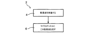
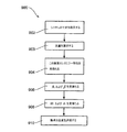
ここで図面を参照すると、図1は、本発明の例示的な実施形態に係る粒子を集束する方法(2)でとられる操作のフローチャートである。 Referring now to the drawings, FIG. 1 is a flowchart of operations taken in method (2) for focusing particles according to an exemplary embodiment of the present invention.
操作4は、懸濁媒質の中の当該粒子の懸濁液を準備する工程を含む。この懸濁媒質は、懸濁液が適切な寸法のチャネルの中を流れるとき、その粒子のうちの少なくともいくつかは、そのチャネル内の集束領域に向かうような粘弾性特性を有する。
いくつかの実施形態では、このチャネルの長さに垂直な集束領域の断面は、そのチャネルの幅に実質的に等しい幅、およびそのチャネルの深さよりもはるかに小さい長さを有する。これらの場合、本願明細書では、集束は「水平方向の」と呼ばれる。 In some embodiments, the cross-section of the focusing region perpendicular to the length of the channel has a width that is substantially equal to the width of the channel and a length that is much smaller than the depth of the channel. In these cases, focusing is referred to herein as “horizontal”.
いくつかの実施形態では、そのチャネルの長さに垂直な集束領域の断面は、そのチャネルの深さに実質的に等しい深さ、およびそのチャネルの幅よりもはるかに小さい幅を有する。これらの場合、本願明細書では、集束は「垂直方向の」と呼ばれる。 In some embodiments, the cross-section of the focusing region perpendicular to the length of the channel has a depth that is substantially equal to the depth of the channel and a width that is much smaller than the width of the channel. In these cases, focusing is referred to herein as “vertical”.
いくつかの実施形態では、そのチャネルの長さに垂直な集束領域の断面は、チャネルの深さよりも実質的に小さい高さ、およびそのチャネルの幅よりもはるかに小さい幅を有する。これらの場合、本願明細書では、集束は3−Dと呼ばれる。 In some embodiments, the cross-section of the focusing region perpendicular to the length of the channel has a height that is substantially less than the depth of the channel and a width that is much smaller than the width of the channel. In these cases, focusing is referred to herein as 3-D.
本発明の例示的な実施形態では、チャネルの深さは100μmより小さく、より浅いチャネルは(他の点では同様の条件下で)より早い集束を可能にする。このチャネルの深さを限定する2つの要因は、あまりに小さいチャネルは詰まりやすいという傾向、および小さいチャネルに流体を流すためにより高い注入口圧力が必要とされることである。 In an exemplary embodiment of the invention, the channel depth is less than 100 μm, and the shallower channel allows faster focusing (under similar conditions otherwise). Two factors limiting the depth of this channel are the tendency for too small channels to become clogged, and the higher inlet pressure required to flow fluid through the small channels.
任意に、チャネルは100μmより小さい幅をも有し(この場合、2−D集束が得られる)、この粒子はチャネルの底部および上面壁から離れて、およびチャネルの垂直方向の壁から離れて集束する。3−D集束では、集束領域は、任意にチャネルの断面に類似しているがそれより小さい断面を有する。任意に、3−D集束領域はそのチャネルと同軸である。 Optionally, the channel also has a width less than 100 μm (in this case, 2-D focusing is obtained) and the particles are focused away from the bottom and top walls of the channel and away from the vertical walls of the channel. To do. For 3-D focusing, the focusing region has a cross-section that is optionally similar to, but smaller than, the cross-section of the channel. Optionally, the 3-D focusing region is coaxial with the channel.
操作6は、チャネルに沿って当該懸濁液を流す工程を含む。 Operation 6 includes flowing the suspension along the channel.
いくつかの例示的な実施形態では、方法2は、粒子を1つずつ並べることをもたらし、これによってフローサイトメーターの中でそれらを検査することが可能になる。
In some exemplary embodiments,
いくつかの実施形態では、この懸濁液は種々のサイズの粒子を含み、懸濁液体の粘弾性特性は、そのチャネル中で当該懸濁液を流す工程が所定のサイズの粒子をその集束領域に向かって選択的に導くような粘弾性特性である。例えば、下記の図5Aおよび図5Bに関連して論じられるいくつかの実施形態では、直径8μmの粒子の95〜99%は集束領域に導かれ、他方、直径5μmの粒子の35〜40%だけが同じ集束領域に導かれる。 In some embodiments, the suspension includes particles of various sizes, and the viscoelastic properties of the suspension are such that the step of flowing the suspension in the channel causes the particles of a predetermined size to be in the focusing region. Viscoelastic properties that lead selectively toward For example, in some embodiments discussed in connection with FIGS. 5A and 5B below, 95-99% of 8 μm diameter particles are directed to the focusing region, while only 35-40% of 5 μm diameter particles. Are led to the same focusing region.
(例示的な懸濁媒質の準備方法)
いくつかの実施形態では、粒子は乾燥しており、媒質粘弾性特性に従って選択される懸濁媒質に懸濁される。
(Exemplary Suspension Medium Preparation Method)
In some embodiments, the particles are dry and suspended in a suspending medium that is selected according to the medium viscoelastic properties.
いくつかの実施形態では、粒子は、不適切な媒質に懸濁されて、準備される。 In some embodiments, the particles are prepared by being suspended in an inappropriate medium.
任意に、準備された懸濁媒質の不適切な粘弾性特性の効果を制御または排除するために、適切な懸濁媒質が過剰に加えられる。 Optionally, an appropriate suspending medium is added in excess to control or eliminate the effects of improper viscoelastic properties of the prepared suspending medium.
あるいはまたは加えて、この懸濁媒質は、適切な粘弾性特性を有する別の懸濁媒質と交換される。 Alternatively or additionally, this suspending medium is exchanged for another suspending medium having suitable viscoelastic properties.
例えば、多くの実施形態では、血液が処理され、分取しようとする粒子は血清に懸濁されて提供される血液細胞である。 For example, in many embodiments, the blood is processed and the particles to be sorted are blood cells provided suspended in serum.
いくつかの実施形態では、生理食塩水がこの血液に加えられる。任意に、加えられた血清の量は血液の量の約15倍、20倍、または25倍である。 In some embodiments, saline is added to the blood. Optionally, the amount of serum added is about 15, 20, or 25 times the amount of blood.
いくつかの実施形態では、この血清は生理食塩水と交換される。任意に、かかる交換は、その血液試料を遠心分離する工程と、血漿を抽出する工程と、抽出された血漿を生理食塩水に懸濁させる工程とを含む。 In some embodiments, the serum is exchanged with saline. Optionally, such exchange includes centrifuging the blood sample, extracting the plasma, and suspending the extracted plasma in saline.
いくつかの実施形態では、この血清を置き換えるために使用される生理食塩水および/またはその血清に加えられる生理食塩水は上記のとおりの改変剤を含む。 In some embodiments, the saline used to replace the serum and / or the saline added to the serum comprises a modifying agent as described above.
いくつかの実施形態では、複数の任意の懸濁媒質が準備され、そのうちの1つは、懸濁媒質の粘弾性特性および集束または分取されるべき粒子の特性、例えば、その粒子のサイズに従って選択される。 In some embodiments, a plurality of optional suspending media is provided, one of which depends on the viscoelastic properties of the suspending media and the properties of the particles to be focused or sorted, eg, the size of the particles Selected.
任意に、この懸濁媒質は、粒子のサイズおよび変形能に応じて選択される。任意に、変形能は有効半径を定義するために使用され、この懸濁媒質は定義された有効半径に応じて選択される。 Optionally, the suspending medium is selected depending on the size and deformability of the particles. Optionally, deformability is used to define the effective radius, and this suspending medium is selected according to the defined effective radius.
任意に、異なる懸濁媒質が、異なるサイズおよび変形能をもつ粒子のために準備される。 Optionally, different suspending media are prepared for particles with different sizes and deformability.
いくつかの実施形態では、試用懸濁媒質がまず使用され、その粒子はその試用懸濁媒質の中で流路に沿ってマイクロチャネルを流され、集束の品質が評価される。集束の品質は、所定の距離を所定の流量でチャネルを流れた後に所定の寸法の集束領域に集束する粒子の割合(%)として任意に定義される。 In some embodiments, a trial suspending medium is used first, and the particles are flowed through a microchannel along the flow path in the trial suspending medium and the focusing quality is evaluated. Focusing quality is arbitrarily defined as the percentage of particles that flow through the channel at a predetermined flow rate at a predetermined distance and then focus on a focusing region of a predetermined size.
この集束が不十分である場合、当該懸濁媒質は任意に手直しされる。任意に、この懸濁媒質は、懸濁媒質の粘弾性特性を改変する改変剤を懸濁媒質に加えることによって手直しされる。任意に、この改変剤はポリアクリルアミド(PAA)などの高分子量ポリマーを含む。このポリアクリルアミド(PAA)は、それが溶解している液体の弾性を高めることが知られている。任意にまたは加えて、この改変剤は、高分子量ポリマー、例えばグリセロールを含む。このグリセロールはそれが溶解している液体の粘度を変化させることが知られている。任意に、1つのポリマーは粘度および弾性の両方を改変する。任意に、弾性を改変するために1以上のポリマーが使用され、粘度を改変するために1以上のポリマーが使用される。 If this focusing is insufficient, the suspending medium is optionally modified. Optionally, the suspending medium is modified by adding a modifying agent to the suspending medium that modifies the viscoelastic properties of the suspending medium. Optionally, the modifying agent includes a high molecular weight polymer such as polyacrylamide (PAA). This polyacrylamide (PAA) is known to increase the elasticity of the liquid in which it is dissolved. Optionally or in addition, the modifying agent comprises a high molecular weight polymer such as glycerol. This glycerol is known to change the viscosity of the liquid in which it is dissolved. Optionally, one polymer modifies both viscosity and elasticity. Optionally, one or more polymers are used to modify elasticity and one or more polymers are used to modify viscosity.
本発明の例示的な実施形態では、集束の品質は、集束される粒子の95%の中心が位置する最も薄い層の幅に基づいて評価される。任意に、その層が薄いほど、集束は良好である。任意に、集束の品質は、集束される粒子の画分に基づいて評価され、その中心は所定の厚さの層内に存在する。 In an exemplary embodiment of the invention, focusing quality is assessed based on the width of the thinnest layer in which 95% of the focused particles are centered. Optionally, the thinner the layer, the better the focusing. Optionally, the quality of focusing is evaluated based on the fraction of particles to be focused, the center of which is in a layer of a given thickness.
加えてまたはあるいは、集束の品質は、ある程度まで集束するために粒子がそのチャネルの中を移動した流路の長さに基づき評価される。例えば、1つの実施形態では、当該粒子の95%が注入口から20mmのところで2μmの厚みの層に集中する場合は、当該粒子の95%が注入口から50mmのところで2μmの厚みの層に集中する場合よりも、集束は良好であると考えられる。
Additionally or alternatively, the quality of focusing is evaluated based on the length of the flow path through which the particles have traveled through the channel to focus to some extent. For example, in one embodiment, if 95% of the particles concentrate in a 2 μm
(例示的なシステム)
図2Aは、本発明の例示的な実施形態に係る、流れる粒子を集束するためのシステム100の略図である。この図は、流体誘導システム145を介して流体源125と流体連通しているチャネル(105)を示す。流体誘導システム145は、検査ゾーン128に向かって流体源125から入力部127を通ってチャネル105へと試料流体を導くために備えられる。任意に、流体誘導システム145は、シリンジポンプを備え、そのピストンは一定かつ制御された速度で押される。市販の適切な流体誘導システムの例は、ケーディー・サイエンティフィック社(KD Scientific Inc.)(米国)のKDS 210 Scientificである。
(Example system)
FIG. 2A is a schematic diagram of a
図2Bはチャネル105の略図である。この図は、チャネル105が壁110および115、底部120および上面壁122を有するとして示す。
FIG. 2B is a schematic diagram of the
試料流体130は懸濁媒質に懸濁された粒子135を含む。この懸濁媒質は、チャネル105の部分140での粒子130の集束を容易にし、この集束を得るために外部場を加える必要性を軽減する粘弾性特性を有する。そうは言うものの、いくつかの実施形態では、任意に集束を強めるため、あるいはまたは加えて、さらなる方向に沿って当該粒子を収束するために、当該技術分野で公知のとおり外部場が加えられる。
動作中は、流体130は流体誘導システム145によってチャネル105の中へと誘導され、粒子135はチャネル105の中に囲まれた集束領域140に導かれる。
In operation,
チャネル105は、底部120に垂直な高さh、および壁110と115との間の幅wを有するマイクロチャネルである。高さhおよび幅wのうちの少なくとも1つは100μmより小さく、任意に約5μm〜約100μm、例えば10、20、50、80、または100μmである。任意に、壁110と115との間の距離wもまた100μmより小さい。任意に、hまたはwのうちの1つは100μmより大きい。1つの例示的な実施形態では、wは1mmであり、hは50μmである。
The
任意に、システム100はまた図3に図示されるキット200を含む。キット200は複数のパッケージ205(図示された実施形態では瓶である)を含み、各パッケージは、所定のサイズの粒子を集束させるために適した粘弾性特性を有する懸濁媒質210を含む。各瓶205は、システム100を用いて集束するためのその瓶の中に懸濁されるべき粒子のサイズを示すラベル215を有する。任意に、このラベルは異なる流量に対して異なる粒径を示す。任意に、このラベルは異なる寸法のシステムに対する異なる粒径を示す。
Optionally,
任意に、キット200(および/またはシステム100)はまた、どの懸濁媒質を用いてどの粒子が集束されるべきであるのかに関する使用説明を含む。任意に、その表示は粒径について触れる。加えてまたはあるいは、その表示は、特定のタイプの細胞、例えば赤血球細胞、白血球、癌性細胞、および/または細菌について触れる。 Optionally, kit 200 (and / or system 100) also includes instructions regarding which suspending medium is used and which particles are to be focused. Optionally, the display touches on particle size. In addition or alternatively, the indication touches on specific types of cells, such as red blood cells, white blood cells, cancerous cells, and / or bacteria.
(例示的な懸濁媒質)
本発明のいくつかの実施形態では、この懸濁媒質は試行錯誤法で選択されまたは選ばれる。
(Exemplary suspension medium)
In some embodiments of the invention, the suspending medium is selected or selected by trial and error methods.
例えば、リン酸緩衝生理食塩水(PBS)の粘弾性特性は、それに360キロダルトンのPVPを加えることによって改変されてもよい。任意に、PVPは、約2%、5%、8%の分散媒質、または任意の中間の濃度を形成するために加えられる。別の例では、PBSの粘弾性特性は、同様の量の70キロダルトンを超える分子量を有するデキストランを加えることによって改変される。加えてまたはあるいは5〜100ppmのPAA、および/またはメチルセルロースが生理食塩水に加えられる。 For example, the viscoelastic properties of phosphate buffered saline (PBS) may be modified by adding 360 kilodaltons of PVP thereto. Optionally, PVP is added to form about 2%, 5%, 8% dispersion medium, or any intermediate concentration. In another example, the viscoelastic properties of PBS are modified by adding a similar amount of dextran having a molecular weight above 70 kilodaltons. In addition or alternatively, 5-100 ppm of PAA and / or methylcellulose is added to the saline.
いくつかの実施形態では、試行錯誤法を導くために理論解析が使用される。例えば、特定のサイズの粒子を所定のチャネルの中で集束させるために必要とされる粘弾性特性が算出され、類似の粘弾性特性を有する媒質が試用懸濁媒質として使用され、必要に応じて上で説明されたように改変される。 In some embodiments, theoretical analysis is used to derive trial and error methods. For example, the viscoelastic properties required to focus particles of a particular size in a given channel are calculated, and a medium with similar viscoelastic properties is used as a trial suspending medium, as needed Modified as described above.
(例示的な応用例)
(例示的なFACS機器)
図4Aは本発明の実施形態に係るシステムを利用するFACS機器400の略図である。機器400は、任意に上記の種類のものであって図2Aおよび図2Bに示されている粒子集束システム100を含む。流体源の中の流体は、適切な粘弾性特性の懸濁媒質の中に懸濁された粒子を含む。システム100は、粒子がチャネル105を通って検査ゾーン405(図1Aの中の128)へと流れた後に、流体源からその粒子を出力する。
(Example application)
(Example FACS equipment)
FIG. 4A is a schematic diagram of a
機器400はまた、システム100から検査ゾーンへと到達した粒子を照射するために検査ゾーン405上に光線を向ける光源410も含む。任意に、システム100によってもたらされる集束は、当該粒子が1つずつ検査ゾーンに到達するという集束である。各粒子は、光源410から到達する光と、任意にその光を散乱することによって、相互作用する。加えてまたはあるいは、その粒子の一部は蛍光をも発する。
The
任意に、光源410はチャネル105の上から粒子を照射する。焦点ゾーンがチャネルの高さの中間までまたは中間において水平方向(すなわち底部120に平行)である実施形態では、この光源は、当該粒子が集束する層に焦点を合わせるように微調整され、チャネル105の幅全体にわたって分散しかつそのチャネルの中間の高さに集められた粒子からの散乱光および/または蛍光を受け取ることに関与している。チャネル105の上側。散乱されたおよび/または発せられた光は検出器(415)によって検出され、コンピュータ420によって分析される。
Optionally,
任意に、コンピュータ420は、各粒子を、分析結果に応じて複数の行き先430のうちの1つへと導くスイッチ425を制御する。例えば、より強い蛍光を有する粒子は、ある1つの行き先へと導かれ、より弱い蛍光の粒子を別の行き先へと導かれる。
Optionally, the
(例示的なレオロジー測定)
本発明のいくつかの実施形態の一態様は、任意に前例のない精度まで、媒質のレオロジー特性を測定することに関する。この方法は、媒質の弾性とその媒質を用いて実現可能な集束の程度との間の関係に基づく。
(Exemplary rheological measurement)
One aspect of some embodiments of the invention relates to measuring the rheological properties of a medium, optionally to unprecedented accuracy. This method is based on the relationship between the elasticity of a medium and the degree of focusing that can be achieved using that medium.
図4Bは、本発明の例示的な実施形態に係る媒質のレオロジー特性を測定する方法500でとられる操作のフローチャートである。
FIG. 4B is a flowchart of operations taken in a
502で、既知のサイズおよびシャープな粒度分布の粒子が媒質に懸濁される。任意に、粒子の量は、得られる懸濁液の体積濃度(すなわち、粒子で占められる当該懸濁液の体積分率)が約0.01%〜1%、例えば、0.1%であるような量である。 At 502, particles of known size and sharp size distribution are suspended in the medium. Optionally, the amount of particles is about 0.01% to 1%, such as 0.1%, of the volume concentration of the resulting suspension (ie the volume fraction of the suspension occupied by the particles) It is an amount like this.
504で、502で得られた懸濁液はマイクロチャネルに流される。 At 504, the suspension obtained at 502 is flowed into the microchannel.
506で、例えば、「理論的誘導」の見出しの節で後述されるようにして、注入口からいくらかの距離でのその粒子の空間分布が測定される。 At 506, the spatial distribution of the particles at some distance from the inlet is measured, for example, as described below in the section “Theoretical guidance”.
508で、懸濁媒質のレオロジー特性が、「理論的誘導」の見出しの節で提供される方程式を使用して測定された空間分布から導き出される。 At 508, the rheological properties of the suspending medium are derived from the spatial distribution measured using the equations provided in the section “Theoretical Derivation”.
任意に、この分析は媒質の粘度に関するデータを使用する。任意に、当該方法はかかるデータを測定する工程を含む。 Optionally, this analysis uses data on the viscosity of the medium. Optionally, the method includes measuring such data.
任意に、方法500は、±10パスカルの精度を提供する市販のレオメーターと比べて、±0.01〜±0.001パスカルのオーダーの精度での媒質の弾性の測定を可能にする。
Optionally, the
(例示的な結合アッセイ)
多くの種類の粒子、例えば、細胞および高分子は、表面に付着しようとする傾向を示す。この傾向は、時折、粒子のアッセイを解析するために使用されることがある。例えば、例示的な実施形態では、モノクローナル抗体が固定された抗原に結合しようとする傾向、または受容体がチャネルの内表面に固定されたリガンドに結合しようとする傾向が研究される。別の例示的な実施形態では、白血球が固定されたリガンドに結合しようとする傾向(インビトロローリングアッセイ(in−vitro rolling assay)として当該技術分野で公知)が研究される。
Exemplary binding assay
Many types of particles, such as cells and macromolecules, tend to adhere to the surface. This trend is sometimes used to analyze particle assays. For example, in an exemplary embodiment, the tendency of a monoclonal antibody to bind to an immobilized antigen or the tendency of a receptor to bind to a ligand immobilized on the inner surface of the channel is studied. In another exemplary embodiment, the tendency of leukocytes to bind to immobilized ligand (known in the art as an in-vitro rolling assay) is studied.
例示的な実施形態では、粒子は、懸濁媒質中で、当該チャネルの底部の上方の所定の高さで薄層に集束され、この集束される粒子がこの底部に固定された結合剤に結合する能力が研究される。 In an exemplary embodiment, the particles are focused into a thin layer at a predetermined height above the bottom of the channel in a suspending medium, and the focused particles bind to a binder fixed to the bottom. The ability to do is studied.
後者の場合、集束は、自由に懸濁した粒子とチャネル底部に固定された結合剤との間の有効相互作用範囲の微調整のための特に役立つツールとしての役割を果たしてもよい。かかる微調整は、そのアッセイの空間的分解能を改善する上で有用であり得る。 In the latter case, focusing may serve as a particularly useful tool for fine-tuning the effective interaction range between freely suspended particles and the binder fixed to the channel bottom. Such fine tuning can be useful in improving the spatial resolution of the assay.
任意に、このチャネルは、注入口近くの、底部に結合剤が固定されていない第1の部分、および第1の部分の下流の、固定された結合剤を有する第2の部分を有する。 Optionally, the channel has a first portion near the inlet with no binding agent fixed at the bottom, and a second portion with fixed binding agent downstream of the first portion.
任意に、第1の部分は、その粒子の大部分、例えば95%がその中心を、チャネルの高さよりはるかに薄い、例えばその高さの5%である層に存在させることができるのに十分長い。 Optionally, the first portion is sufficient to allow a majority of the particles, e.g. 95%, to be present in a layer whose center is much thinner than the channel height, e.g. 5% of its height. long.
任意に、第2の部分は第1の部分と同じ高さであり、固定された結合剤に引き付けられない粒子は、それが第1の部分において動くのと実質的に同じように第2の部分において動く。任意に、第2の部分は、当該結合剤に結合し得るすべての粒子の大部分、例えば95%を結合するのに十分長く、結合しない粒子のみが第2の部分から出る。 Optionally, the second portion is the same height as the first portion, so that the particles that are not attracted to the fixed binder will be substantially the same as it moves in the first portion. Move in the part. Optionally, the second portion is long enough to bind the majority of all particles that can be bound to the binder, eg, 95%, and only unbound particles exit the second portion.
任意に、複数のチャネルが使用され、各チャネルは異なる高さを有し、そのため、底部に固定された結合剤と半分の高さにある薄層で集束された粒子との間の相互作用距離は、結合剤への粒子の付着が第1の閾値未満である最小のチャネル高さ、および結合剤への粒子の付着が第2の閾値より高い最大のチャネル高さに基づく。例えば、この相互作用距離は、当該粒子の5%未満が吸着する最小の高さと、その粒子の少なくとも95%が吸着する最大高さとの間の中点として定義されてもよい。 Optionally, multiple channels are used, each channel having a different height, so the interaction distance between the binder fixed at the bottom and the thin-layer focused particles at half height Is based on the minimum channel height at which particle adhesion to the binder is below the first threshold and the maximum channel height at which particle adhesion to the binder is above the second threshold. For example, this interaction distance may be defined as the midpoint between the minimum height at which less than 5% of the particles adsorb and the maximum height at which at least 95% of the particles adsorb.
任意に、結合剤と粒子との間の相互作用距離は、第2の部分の最初から特定の距離のところでの結合に基づき評価される。 Optionally, the interaction distance between the binder and the particles is evaluated based on the binding at a specific distance from the beginning of the second part.
任意に、すべてのチャネルが同じ長さの第1の部分を有する。任意に、異なるチャネルは、すべてのチャネルにおいて同じ程度まで粒子を集束させるように設計された第1の部分を有する。任意に、これは、より長い第1の部分がより深いチャネルに関連する異なる長さの第1の部分を用いて成し遂げられる。任意にまたは加えて、すべて同じ集束力の第1の部分を有することは、流体を異なるチャネルへと誘導して、より高い流れの流体をより深いチャネルに誘導する流れ誘導システムを微調整することによって成し遂げられる。 Optionally, all channels have a first portion of the same length. Optionally, the different channels have a first portion designed to focus the particles to the same extent in all channels. Optionally, this is accomplished using a different length of the first portion where the longer first portion is associated with a deeper channel. Optionally or additionally, having a first portion of all the same focusing force can fine tune the flow guidance system that directs fluid to different channels and directs higher flow fluid to deeper channels Achieved by.
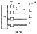
図4Cは、本発明の例示的な実施形態に係る粒子−結合剤相互作用を研究するための装置の略図である。 FIG. 4C is a schematic diagram of an apparatus for studying particle-binder interactions according to an exemplary embodiment of the present invention.
装置600は、各々がタンク610から試料流体を受ける複数のチャネル605を備える。任意に、各チャネル105は、それ自身の流れ誘導システム645を有し、この流れ誘導システム645は、流体が他のチャネルのいずれかへと誘導される流量からは独立した流量で、試料流体をそれと関連するチャネルへと導くために任意に制御可能である。
Apparatus 600 includes a plurality of
図示された実施形態では、各チャネル605は第1の部分620を有する。任意に、各流れ誘導システムは、第1の部分の終点で、その粒子の約90%の中心がチャネルの高さの中央の薄層を占めるように作動される。
In the illustrated embodiment, each
結合剤がチャネルの底部に固定された第2の部分625もまた図示された実施形態に示されている。各チャネルより上で、第2の部分の始点後いくらかの距離で、この地点に到達する粒子の数を評価するために、カメラの下のチャネル中の粒子を撮像するカメラ630が示されている。
Also shown in the illustrated embodiment is a second portion 625 in which a binder is secured to the bottom of the channel. A
任意に、結合量は、第2の部分に入る粒子の数と第2の部分を離れる粒子の数との間の比に基づいて、評価される。 Optionally, the amount of binding is evaluated based on the ratio between the number of particles entering the second portion and the number of particles leaving the second portion.
(理論的誘導)
以下では、所定のサイズの粒子を集束させるのに適した懸濁媒質を選択する際に当業者を手助けするための理論が提示され、その理論および本発明のいくつかの実施形態の実行可能性を支持するために実験結果が報告される。
(Theoretical induction)
In the following, a theory is presented to assist a person skilled in the art in selecting a suitable suspending medium to focus particles of a given size, and the feasibility of that theory and some embodiments of the present invention. Experimental results are reported to support
本発明の一態様は、流れ抜ける(flow−through)構造における希薄な懸濁液の中の粒子または細胞の受動的かつ調整可能な集束のための方法論に関する。この方法論は、粒子を壁から離してチャネルの中央面に向かって制御可能な様式で駆動するために、希薄なポリマー溶液の圧力駆動による流れにおいて生じる固有の非線形の弾力がどのように活用され得るかを実証する微小流体の実験の結果によって支持される。本発明者らは、基礎となる移動機構を記述するための分析モデルの結果を提示し、横方向の粒子分布の微調整のための方法を提案する。最後に、理論的予測値を立証するために設計された実験の結果が提供され、十分に考察される。 One aspect of the invention relates to a methodology for passive and tunable focusing of particles or cells in a dilute suspension in a flow-through structure. This methodology shows how the inherent non-linear elasticity that occurs in the pressure-driven flow of dilute polymer solutions can be exploited to drive the particles away from the wall and in a controllable manner toward the central plane of the channel. Supported by the results of microfluidic experiments to demonstrate this. We present the results of an analytical model to describe the underlying movement mechanism and propose a method for fine-tuning the lateral particle distribution. Finally, the results of experiments designed to validate theoretical predictions are provided and fully considered.
本発明者らの実験では、参照により本願明細書に援用したものとするA.Branskyら、Biosens.Bioelectron.22、165(2006);Microvasc.Res.73、7(2007)、(以降、Branskyら2007)に記載されるフォトリソグラフィーを使用して顕微鏡用カバーガラスに製作した断面h×w=45×103μm2の浅い微小流体用チャネルを使用した。シリンジポンプ(KDS 210、ケーディー・サイエンティフィック)を使用して、種々の一定流量で(0.1〜1cm/sの典型的な速度で)マイクロチャネル注入口を通してポリスチレン(PS)ミクロスフェア(デューク・サイエンティフィック(Duke Scientific))の希薄に(0.1体積%未満)分散した懸濁液を注入した。高速CCDカメラ(CPL MS100O カナディアン・フォトニック・ラボ(Canadian Photonic Labs))を正立顕微鏡(ニコン(Nikon) 80i)に取り付けた。種々の深さで、注入口から20mm下流で、マイクロチャネルの中央を(側壁から距離w/2のところを)流れるミクロスフェアの膜を、Barnskyら、2007によって記載されている特注設計の画像処理ソフトウェアによるさらなる解析のために直接PCに記録した。このアルゴリズムは、粒子を数えて、深さ約1μmの垂直方向の薄層におけるそれら粒子の速度を算出することができる。
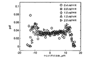
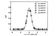
In our experiments, it is incorporated by reference in this specification. Bransky et al., Biosens. Bioelectron. 22, 165 (2006); Microvasc. Res. 73, 7 (2007) (hereinafter referred to as Bransky et al. 2007), a shallow microfluidic channel having a cross-section h × w = 45 × 10 3 μm 2 fabricated on a microscope cover glass is used. did. Polystyrene (PS) microspheres (Duke's) through microchannel inlets at various constant flow rates (at typical rates of 0.1-1 cm / s) using syringe pumps (
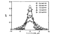
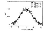
本発明者らは、特定深さの焦点に含まれる粒子の割合を、その流れ方向の速度で除算して1に正規化したものとして、粒子分布関数(PDF)を定義する。この定義によれば、粒子が周囲の流れの流線に追従するのであれば、PDFは一定かつ流量非依存的でなければならない。本発明者らは、まず、脱イオン水の中に84体積%のグリセロールを含む粘性の高いニュートン挙動を示す液体に懸濁した直径8μmのPSミクロスフェアを用いて参照実験を行った。溶液のせん断粘度を歪み制御されたレオメーター(ARES、レオメトリック・サイエンティフィック(Rheometric Scientific))を使用して測定したところ、25℃で0.063Pa・sであることが判明した。図5aは、流量を変えた際の実験によるPDF 対 中心を外れた垂直方向の距離を表す。各点は、数百もの個々の測定値に基づく平均値に対応する。粒子分布は流量とともには変化せず、ほとんど一定であることが容易に分かる。本発明者らは、8重量% ポリビニルピロリドン(PVP、MW 約3.6×10⁵;シグマ・アルドリッチ(Sigma−Aldrich))水溶液中に懸濁したPSミクロスフェアを用いてこの実験を繰り返し、得られたPDFを図5bにプロットした。集束は流量の増加とともに高まりながら、この粒子は壁から離れて移動して中央平面に集中する傾向があることが容易に分かる。外部場がない場合の粒子集束(変形により誘導される移動、慣性効果、およびせん断によって誘導される移動)に対するこれまでに示唆された説明は、図5aおよび図5bに示される結果を説明するためには、すべて不十分であるように思われる。明らかに、変形により誘導される移動は剛性の高いミクロスフェアには当てはまらず、慣性効果は両方の溶液で同様の結果をもたらすはずであり、他方、せん断によって誘導される移動は濃厚な懸濁液においてのみ観察される。それゆえ、新規な説明が提示されるべきである。 We define the particle distribution function (PDF) as the proportion of particles contained in a focus at a specific depth, normalized by dividing by the velocity in the flow direction. According to this definition, if the particle follows the streamline of the surrounding flow, the PDF must be constant and flow independent. The inventors first performed a reference experiment using PS microspheres having a diameter of 8 μm suspended in a liquid having a high viscosity Newtonian behavior containing 84% by volume of glycerol in deionized water. The shear viscosity of the solution was measured using a strain-controlled rheometer (ARES, Rheometric Scientific) and found to be 0.063 Pa · s at 25 ° C. FIG. 5a represents the experimental PDF vs. off-center vertical distance when changing the flow rate. Each point corresponds to an average value based on hundreds of individual measurements. It is easy to see that the particle distribution does not change with flow rate and is almost constant. We repeated this experiment using PS microspheres suspended in an aqueous solution of 8% by weight polyvinylpyrrolidone (PVP, MW about 3.6 × 10 5 ; Sigma-Aldrich). The resulting PDF was plotted in FIG. 5b. It can be readily seen that the particles tend to move away from the wall and concentrate in the central plane, while focusing increases with increasing flow rate. Previously suggested explanations for particle focusing in the absence of an external field (deformation-induced movement, inertial effects, and shear-induced movement) are to explain the results shown in FIGS. 5a and 5b. It seems that everything is inadequate. Clearly, deformation-induced movements do not apply to rigid microspheres, and inertial effects should yield similar results in both solutions, while shear-induced movements are concentrated suspensions. Observed only in Therefore, a new explanation should be presented.
本発明者らは、次に、横方向の粒子の移動が、圧縮による非線形的な弾性力の不均衡によって駆動されることを実証することにする。せん断が加わった流れにおけるこれらの力は、第一法線応力差および第二法線応力差、それぞれ
![]()
![]()
![]()
![]()
あるいは、(2)における深さ平均による横方向の速度は、容易に
本発明者らはさらにブラウン揺動力、粒子間および壁間の水力学的相互作用を無視し、かつ当該粒子の流れ方向の速度Uはその中心では無かく乱流の速度、uにおよそ等しい[18]と仮定する。それゆえ、当該粒子の軌跡は以下の方程式の解である。
このPVP溶液についてのN1の大きさは小さすぎて、定常せん断試験で信頼性高く測定することはできない。その代わり、本発明者らは、振動数、ωの関数としての動的剛性(「貯蔵弾性率」)、G、の小振幅の振動せん断測定を実施した(図6を参照)。低い値の
![]()
![]()
レオロジー特性およびチャネルの寸法が与えられると、αを直接算出することができ、そのあと(3)の解を実験データにフィットさせることによって増倍定数Cが見出され得る。y95(μm)に対応する値を、種々の流量について図5bに示したデータから算出し、白抜き三角形として図7に提示する。図7の真ん中の曲線は実験データへの理論的モデルの最良のフィットに対応し、これら2つのものの間には優れた一致がある。最適のフィットから増倍定数
![]()
![]()
定常状態でのブラウン揺動力に起因するスケール化されたPDFの幅、2ζBは、条件、Pe=aV/D0=1から見積もることができる。式中、Vは(2)によって与えられ、D0は単一の粒子のストークス−アインシュタインの拡散率であり、Peはペクレ数である。α=0.5μmおよび
式(2)から
従って、
8μmおよび5μmのミクロスフェアの得られるPDFはそれぞれ図8aおよび図8bに与えられる。予想されるとおり、PDFはほとんど流量に依存しないことが容易に理解できる。粒径効果は明らかである:PDF分布はより大きい粒子ほどより狭い。対応するy95の値は図8のPDFから算出することができ、それらは、5μm粒子(白抜きひし形)および8μm粒子(白抜き正方形)について、図7に流量に対して図示される。PAA溶液におけるy95の理論的予測値[図7の一番上および一番下の曲線]は、C=0.301とした方程式(3)の解に基づいており、調整可能なパラメータはまったく含んでいない。予想されるとおり、8μmの粒子についての集束効果は、このPVP溶液においてよりもこのPAA溶液において強く、粒径の効果は大きい。(調整可能なパラメータなしの)理論的予測値とこの実験データとの比較から優れた一致が示され、上記粘弾性集束の仮説が検証される。8μm粒子についての実験的分解能は不十分であるので、理論的予測値と図7におけるPAA溶液中での8μm粒子についての実験との間の一致は、5μm粒子についての場合ほどには正確ではない。これらの粒子は4μm未満の非常に薄い層の中に集束される。図8(a)参照。 The resulting PDFs of 8 μm and 5 μm microspheres are given in FIGS. 8a and 8b, respectively. As expected, it can be easily understood that PDF is almost independent of flow rate. The particle size effect is obvious: the PDF distribution is narrower for larger particles. Corresponding y 95 values can be calculated from the PDF of FIG. 8, which are illustrated for flow rates in FIG. 7 for 5 μm particles (open diamonds) and 8 μm particles (open squares). Theoretical prediction value of y 95 in PAA solution [top and bottom curves in Fig. 7] is based on the solution of C = 0.301 and the equation (3), adjustable parameters at all Does not include. As expected, the focusing effect for 8 μm particles is stronger in this PAA solution than in this PVP solution and the effect of particle size is greater. Comparison of theoretical predictions (without tunable parameters) with this experimental data shows good agreement and validates the viscoelastic focusing hypothesis. Since the experimental resolution for 8 μm particles is insufficient, the agreement between the theoretical predictions and the experiment for 8 μm particles in the PAA solution in FIG. 7 is not as accurate as for 5 μm particles. . These particles are focused in a very thin layer of less than 4 μm. Refer to FIG.
(集束予測方法)
図9Aは、本発明の実施形態に係る所定のフローシステムで所定の懸濁媒質の集束の品質を予測する方法900でとられるべき操作のフローチャートである。
(Focusing prediction method)
FIG. 9A is a flowchart of operations to be taken in a
操作902で、このシステムの物理的寸法が提供される。これらの寸法には、任意に、この微小流体用チャネルの構造(その幅w、深さh(すなわち、このチャネルの半分の深さを表すd=h/2)、および注入口と検査ゾーンとの間の長さを含む);および集束されるべき粒子の見積もられるサイズが含まれる。
At
903で、実験での設定で使用されることになる流量Q、が選択され、平均の流れ方向の速度
904で、この所定の懸濁媒質のレオロジー特性が見積もられる。見積もられるレオロジー特性には、任意に、せん断速度
![]()
![]()
906で、方程式
任意に、この見積もりは、粘度測定での等式
![]()
![]()
N1が市販のレオメーターによって直接測定されるのに十分大きい(典型的には、数十Paのオーダーにある)場合、N1は任意に直接測定される。 If N 1 is large enough to be measured directly by a commercially available rheometer (typically on the order of tens of Pa), N 1 is arbitrarily measured directly.
908で、方程式
![]()
![]()
910で、集束の品質は、操作902および903でもたらされるデータならびに操作904〜908で得られた見積もり値を使用して上記の方程式4を解くことによって評価される。任意に、集束の品質は、試験粒子の無次元の位置ζ=y/dによって評価される。例えば、流れ方向に注入口から20mmの距離で、d=40μmの半分の深さを有するマイクロチャネルの中の深さ4μmの中心層内に粒子の何%が垂直方向に集束されるであろうかを知りたい場合は、ζ=4/40=0.1およびξ=2000/40=50を用いてζ0について式(4)を解くべきである。例えば、得られたζ0=0.75という値は、その粒子のおよそ75%は、注入口から下流の20mmの距離で深さ4μmの中央のコア内に集束されるであろうということを意味する。
At 910, the quality of the focus is evaluated by solving
単分散の直鎖状ポリマーの多くの希釈溶液は、特定の明確なレオロジー挙動を示す(Boger液体として当該技術分野で公知):これによると、
用語「単分散性ポリマー」は、この文脈では、狭い分子量の分布を有するポリマーを表すために使用される。希薄溶液でBoger液体挙動をもたらす直鎖状ポリマーの例としては、単分散性ポリアクリルアミドおよびポリエチレングリコールが挙げられる。 The term “monodisperse polymer” is used in this context to denote a polymer having a narrow molecular weight distribution. Examples of linear polymers that provide Boger liquid behavior in dilute solutions include monodisperse polyacrylamide and polyethylene glycol.
Boger液体の場合、n=1およびβ=2であり、集束の品質の評価はかなり単純になる。かかる単純化された方法(900’)のフローチャートが図9bに提示される。 In the case of Boger liquid, n = 1 and β = 2, and the evaluation of focusing quality is considerably simplified. A flowchart of such a simplified method (900 ') is presented in Fig. 9b.
図9Bは、本発明の実施形態に係る所定のフローシステムで所定の懸濁媒質の集束の品質を予測する方法900でとられるべき操作のフローチャートである。
FIG. 9B is a flowchart of operations to be taken in a
図9bの中の操作902および903は、図9aの中の同じ操作とまったく同様である。
904’で、平均せん断速度およびせん断速度の平均勾配が、操作902および903で提供される値から、式:
![]()
![]()
906’で、粘性応力τおよび法線応力N1の値が測定され、Wi=N1/τが算出される。τおよびN1の測定は、任意に、市販のレオメーターを用いて実施される。これらの値は、任意に、904’で算出された
正確な法線応力測定は、通常は市販のレオメーターによっては利用できず、それゆえ法線応力は、1つの周波数
908’で、ワイセンベルグ数Wi=N1/τは906’で得られたデータを使用して算出される。 At 908 ′, the Weissenberg number Wi = N 1 / τ is calculated using the data obtained at 906 ′.
908’で、その粒子の平均横方向速度
![]()
![]()
![]()
![]()
910’で、粒子がチャネルの中心の水平方向面に完全に集束される流れ方向の距離は、
(全般的な注釈)
本願から成立する特許の存続期間の間に多くの関連する懸濁媒質、フローサイトメーター、およびFACS機器が開発されるであろうということが予想され、当該用語に対応する用語の範囲は、すべてのかかる新しい技術を最初から包含することが意図されている。
(General notes)
It is anticipated that many related suspending media, flow cytometers, and FACS equipment will be developed during the lifetime of the patent granted from this application, and the term ranges corresponding to that term are all It is intended to encompass such new technologies from the beginning.
用語「含む(comprises)」、「含む(comprising)」、「含む(includes)」、「含む(including)」、「有する」およびそれらの同根語は、「〜を含むが、これらに限定されない」ことを意味する。 The terms “comprises”, “comprising”, “includes”, “including”, “having” and their conjuncts include “including but not limited to”. Means that.
用語「例示的な」は、「例、実例または図解としての役割を果たす」ことを意味する。 The term “exemplary” means “serving as an example, instance or illustration”.
本願明細書で数値範囲が示される場合はいつでも、それは、示された範囲内のあらゆる引用された数字(分数または整数)を含むことが意図されている。第1の示された数と第2の示された数「との間の範囲の(ranging)/範囲にある(ranges)」および第1の示された数「から」第2の示された数「までの範囲の(ranging)/範囲にある(ranges)」との語句は、本願明細書においては互換的に使用され、第1および第2の示された数ならびにそれらの間のすべての分数および整数を含むことが意図されている。 Whenever a numerical range is indicated herein, it is intended to include any cited numerals (fractional or integer) within the indicated range. The first indicated number and the second indicated number “between / ranging” and the first indicated number “from” the second indicated number The phrase “ranging / ranges” is used interchangeably herein and includes the first and second indicated numbers as well as all in between It is intended to include fractions and integers.
分かりやすさのために別々の実施形態に関連して記載されている本発明の特定の特徴は、1つの実施形態で組み合わせて提供されてもよいことが予想される。逆に、簡潔さのために1つの実施形態に関連して記載されている本発明の種々の特徴は、別々に、またはあらゆる適切なサブコンビネーションとして、または本発明のいずれかの他の記載された実施形態において適切であるとして、提供されてもよい。種々の実施形態に関連して記載された特定の特徴は、それらの要素がなければその実施形態が機能しない場合でない限り、それらの実施形態の必須の特徴とは考えられないものとする。 It is envisioned that certain features of the invention described in connection with separate embodiments for clarity may be provided in combination in one embodiment. Conversely, the various features of the invention described with reference to one embodiment for the sake of brevity are described separately or as any suitable sub-combination, or any other description of the invention. May be provided as appropriate in certain embodiments. Certain features described in connection with various embodiments are not to be considered essential features of those embodiments, unless such embodiments would not work without those elements.
本発明はその具体的な実施形態に関連して説明されてきたが、多くの変更態様、修正態様およびバリエーションが当業者に明らかになることは明白である。従って、本発明は、添付の特許請求の範囲の趣旨および幅広い範囲のうちに含まれるすべてのかかる変更態様、修正態様およびバリエーションを包含することが意図されている。 Although the invention has been described with reference to specific embodiments thereof, it is evident that many changes, modifications, and variations will be apparent to those skilled in the art. Accordingly, the present invention is intended to embrace all such alterations, modifications and variations that fall within the spirit and broad scope of the appended claims.
本願明細書で言及されたすべての刊行物、特許および特許出願は、各々の個々の刊行物、特許および特許出願が具体的におよび個々に参照により本願明細書に援用したものとすると示された場合と同じ程度まで、参照によりその全体を本願明細書に援用したものとする。加えて、本願におけるあらゆる参考文献の引用または特定は、かかる参考文献が本発明にとっての先行技術として利用できるということを認めるものとは解釈されないものとする。節の見出しが使用されるところでは、それらは必ずしも限定するものとは解釈されるべきではない。 All publications, patents, and patent applications mentioned in this application are indicated to be incorporated herein by reference, with each individual publication, patent, and patent application specifically and individually. To the same extent as in the case, the entire contents thereof are incorporated herein by reference. In addition, citation or identification of any reference in this application shall not be construed as an admission that such reference is available as prior art to the present invention. Where section headings are used, they should not necessarily be construed as limiting.
Claims (15)
第1の懸濁媒質中の前記粒子の懸濁液を準備する工程と、
チャネルの中で前記懸濁液を流す工程であって、前記チャネルは長軸および前記長軸に垂直な断面を有しかつ100μmより小さい少なくとも1つの断面寸法を有し、そのために前記チャネルの中で前記懸濁液を流す前に前記第1の懸濁媒質の中に前記粒子を懸濁させる工程と、
を含み、前記第1の懸濁媒質は、前記チャネル中で前記懸濁液を流すことが前記チャネル内部の集束領域での前記粒子の濃度を増加させるような粘弾性特性を有する、方法。 A method of focusing particles,
Providing a suspension of the particles in a first suspending medium;
A step of flowing the suspension in the channel, the channel will have a and 100μm smaller at least one cross-sectional dimension having a cross-section perpendicular to the long axis and the long axis, in said channel for the a step of suspending said particles in said first suspending medium before flowing the suspension in,
Wherein the first suspending medium has viscoelastic properties such that flowing the suspension in the channel increases the concentration of the particles in the focusing region inside the channel.
第2の懸濁媒質中に前記粒子がある懸濁液を得る工程と、
前記第2の懸濁媒質を前記第1の懸濁媒質に加える工程と
を含む、請求項1に記載の方法。 Preparing the suspension comprises:
Obtaining a suspension with said particles in a second suspending medium;
Adding the second suspending medium to the first suspending medium.
種々の粘弾性特性を有する複数の懸濁媒質を準備する工程と、
前記媒質の粘弾性特性に応じて前記複数の懸濁媒質から前記第1の懸濁媒質を選択する工程と、
前記粒子を前記選択された懸濁媒質に懸濁させる工程と
を含む、請求項1に記載の方法。 The step of preparing the suspension
Providing a plurality of suspending media having various viscoelastic properties;
Selecting the first suspension medium from the plurality of suspension media according to the viscoelastic properties of the medium;
Suspending the particles in the selected suspending medium.
チャネルと、
試料流体を含む流体源であって、前記試料流体が、液体の中に懸濁されている粒子を含む、流体源と、
前記流体源から注入口を経由して前記チャネルへと前記試料流体を誘導するように構成された流体誘導システムであって、そのために前記流体源から注入口を経由して前記チャネルへと前記試料流体を誘導する前に前記液体の中に前記粒子を懸濁させる流体誘導システムと、
を含み、前記液体は、前記チャネルの中の集束領域で前記粒子を集束させるために外部力場を加える必要性を緩和するような粘弾性特性を有するシステム。 A system for focusing flowing particles,
Channel,
A fluid source comprising a sample fluid, wherein the sample fluid comprises particles suspended in a liquid ;
A fluid guidance system configured to direct the sample fluid from the fluid source to the channel via an inlet, to which the sample is directed from the fluid source to the channel via an inlet. A fluid guidance system that suspends the particles in the liquid before directing fluid;
Hints, the liquid system having a viscoelastic characteristic as to alleviate the need for applying an external force field for focusing said particles in the focal region in said channel.
前記尋問光線を使用して前記検査ゾーンで前記粒子を検出するように構成された検出器と
を含む、請求項12に記載のシステム。 A light source providing interrogation rays in sensing communication with the focusing region in the examination zone downstream from the inlet;
13. A system according to claim 12, comprising a detector configured to detect the particles in the examination zone using the interrogation beam.
Applications Claiming Priority (3)
| Application Number | Priority Date | Filing Date | Title |
|---|---|---|---|
| US92499807P | 2007-06-07 | 2007-06-07 | |
| US60/924,998 | 2007-06-07 | ||
| PCT/IL2008/000772 WO2008149365A2 (en) | 2007-06-07 | 2008-06-05 | Systems and methods for focusing particles |
Related Child Applications (1)
| Application Number | Title | Priority Date | Filing Date |
|---|---|---|---|
| JP2013161659A Division JP5901582B2 (en) | 2007-06-07 | 2013-08-02 | Method and apparatus for focusing particles |
Publications (3)
| Publication Number | Publication Date |
|---|---|
| JP2010529452A JP2010529452A (en) | 2010-08-26 |
| JP2010529452A5 JP2010529452A5 (en) | 2011-07-07 |
| JP5337151B2 true JP5337151B2 (en) | 2013-11-06 |
Family
ID=39800715
Family Applications (2)
| Application Number | Title | Priority Date | Filing Date |
|---|---|---|---|
| JP2010510958A Active JP5337151B2 (en) | 2007-06-07 | 2008-06-05 | System and method for focusing particles |
| JP2013161659A Active JP5901582B2 (en) | 2007-06-07 | 2013-08-02 | Method and apparatus for focusing particles |
Family Applications After (1)
| Application Number | Title | Priority Date | Filing Date |
|---|---|---|---|
| JP2013161659A Active JP5901582B2 (en) | 2007-06-07 | 2013-08-02 | Method and apparatus for focusing particles |
Country Status (5)
| Country | Link |
|---|---|
| US (2) | US8642288B2 (en) |
| EP (1) | EP2153199B1 (en) |
| JP (2) | JP5337151B2 (en) |
| CN (2) | CN101772697B (en) |
| WO (1) | WO2008149365A2 (en) |
Families Citing this family (24)
| Publication number | Priority date | Publication date | Assignee | Title |
|---|---|---|---|---|
| US9494570B2 (en) | 2008-10-02 | 2016-11-15 | Pixcell Medical Technologies Ltd. | Optical imaging based on viscoelastic focusing |
| CN107367406B (en) | 2011-03-09 | 2020-03-06 | 彼克斯赛尔医疗科技有限公司 | Disposable cartridge for preparing a sample fluid containing cells for analysis |
| GB201113309D0 (en) * | 2011-08-02 | 2011-09-14 | Izon Science Ltd | Characterisation of particles |
| CA2876358A1 (en) * | 2012-06-22 | 2013-12-27 | Malvern Instruments Limited | Particle characterization |
| US10509976B2 (en) | 2012-06-22 | 2019-12-17 | Malvern Panalytical Limited | Heterogeneous fluid sample characterization |
| US20150362421A1 (en) * | 2012-06-22 | 2015-12-17 | Malvern Instruments Limited | Particle characterization |
| WO2014017186A1 (en) * | 2012-07-25 | 2014-01-30 | ソニー株式会社 | Microparticle measurement device and liquid supply method for microparticle measurement device |
| US9372144B2 (en) * | 2013-10-01 | 2016-06-21 | Owl biomedical, Inc. | Particle manipulation system with out-of-plane channel |
| WO2014145983A1 (en) * | 2013-03-15 | 2014-09-18 | Iris International, Inc. | Sheath fluid systems and methods for particle analysis in blood samples |
| WO2014146030A1 (en) | 2013-03-15 | 2014-09-18 | Iris International, Inc. | Flowcell systems and methods for particle analysis in blood samples |
| WO2015033090A1 (en) * | 2013-09-03 | 2015-03-12 | Izon Science Limited | Measurement of particle charge |
| US10307760B2 (en) | 2014-01-30 | 2019-06-04 | The General Hospital Corporation | Inertio-elastic focusing of particles in microchannels |
| EP2907574A1 (en) | 2014-02-13 | 2015-08-19 | OWL Biobedical, Inc. | Microfluidic system with viscoelastic fluid |
| EP3245002A4 (en) | 2015-01-14 | 2018-08-01 | Pixcell Medical Technologies Ltd. | Disposable cartridge for sample fluid analysis |
| PL3282913T3 (en) * | 2015-04-17 | 2019-03-29 | Koninklijke Philips N.V. | Dust processing |
| KR101855490B1 (en) * | 2016-01-22 | 2018-05-08 | 한국과학기술원 | Method For Separating And Washing Of Microparticles Via A Stratified Coflow Of Non-Newtonian And Newtonian Fluids |
| JP6134402B1 (en) * | 2016-01-29 | 2017-05-24 | シスメックス株式会社 | Biological sample imaging apparatus and biological sample imaging method |
| CN106248528A (en) * | 2016-09-27 | 2016-12-21 | 中国石油天然气股份有限公司 | A Method for Evaluating the Elasticity of Polymers |
| EP3631415B1 (en) | 2017-06-02 | 2026-03-25 | The General Hospital Corporation | Oscillatory focusing of particles in channels |
| CN108627448A (en) * | 2018-06-05 | 2018-10-09 | 江苏卓微生物科技有限公司 | The method of counting micro particles |
| US11185861B2 (en) | 2018-06-13 | 2021-11-30 | International Business Machines Corporation | Multistage deterministic lateral displacement device for particle separation |
| WO2022072503A1 (en) * | 2020-09-29 | 2022-04-07 | 1087 Systems, Inc | Graded bioprocess monitoring and fluid self-modulation |
| EP4083607A1 (en) | 2021-04-26 | 2022-11-02 | ETH Zurich | Method and microfluidic device for studying cell deformations |
| JP7152622B1 (en) * | 2022-03-30 | 2022-10-12 | ポーラ化成工業株式会社 | Bubble concentration measurement method for ultra-fine bubbles |
Family Cites Families (23)
| Publication number | Priority date | Publication date | Assignee | Title |
|---|---|---|---|---|
| JPS576338A (en) * | 1980-06-12 | 1982-01-13 | Kyoto Daiichi Kagaku:Kk | Method and device for measuring degree of flocculation of finely divided particles quantitatively |
| FR2621123B1 (en) * | 1987-09-30 | 1989-12-01 | Commissariat Energie Atomique | METHOD FOR MANUFACTURING A DEVICE FOR OPTICAL ANALYSIS OF A MICROPARTICLE STREAM AND APPLICATION TO THE MANUFACTURE OF A CYTOFLUORIMETER |
| JP2813988B2 (en) * | 1989-08-08 | 1998-10-22 | 東亜医用電子株式会社 | Erythrocyte deformability measurement method and apparatus |
| JP3467310B2 (en) * | 1994-04-21 | 2003-11-17 | シスメックス株式会社 | Leukocyte analysis reagent and leukocyte classification method |
| FR2734637B1 (en) * | 1995-05-24 | 1997-08-14 | Abx Sa | DEVICE FOR OPTICAL INSPECTION OF A FLUID, PARTICULARLY FOR HEMATOLOGICAL ANALYSIS |
| JPH09126989A (en) * | 1995-11-07 | 1997-05-16 | Hitachi Ltd | Flow-type particle image analyzer |
| US5808737A (en) * | 1996-02-29 | 1998-09-15 | Sienna Biotech, Inc. | Pre-analysis chamber for a flow particle analyzer |
| JPH09318523A (en) * | 1996-05-29 | 1997-12-12 | Toa Medical Electronics Co Ltd | Parameter analysis method and apparatus using the same |
| US6723290B1 (en) * | 1998-03-07 | 2004-04-20 | Levine Robert A | Container for holding biologic fluid for analysis |
| EP1210578A4 (en) * | 1999-08-13 | 2007-02-21 | U S Genomics | METHOD AND APPARATUS FOR STRETCHING POLYMERS |
| CA2396015A1 (en) * | 1999-12-29 | 2001-07-05 | Union Biometrica, Inc. | High viscosity sheath reagent for flow cytometry |
| US20040070757A1 (en) * | 2000-12-29 | 2004-04-15 | Moore Richard Channing | High viscosity sheath reagent for flow cytometry |
| AU2002320507A1 (en) * | 2001-07-13 | 2003-01-29 | Caliper Technologies Corp. | Microfluidic devices and systems for separating components of a mixture |
| CN100436574C (en) * | 2001-09-06 | 2008-11-26 | 基因描绘系统有限公司 | Rapid detection of replicating cells |
| US6746872B2 (en) * | 2002-01-16 | 2004-06-08 | Lifescan, Inc. | Control compositions and methods of use for coagulation tests |
| JP2003302330A (en) * | 2002-04-12 | 2003-10-24 | Asahi Kasei Corp | Flat plate flow cell device |
| US6794671B2 (en) * | 2002-07-17 | 2004-09-21 | Particle Sizing Systems, Inc. | Sensors and methods for high-sensitivity optical particle counting and sizing |
| US7115230B2 (en) * | 2003-06-26 | 2006-10-03 | Intel Corporation | Hydrodynamic focusing devices |
| AU2005220150A1 (en) * | 2004-02-13 | 2005-09-15 | The University Of North Carolina At Chapel Hill | Functional materials and novel methods for the fabrication of microfluidic devices |
| JP4528664B2 (en) * | 2004-04-22 | 2010-08-18 | 興和株式会社 | Fluorescent particle counter |
| ITBO20040420A1 (en) * | 2004-07-07 | 2004-10-07 | Type S R L | METAL CUTTING AND FORMING MACHINE |
| US7811438B2 (en) * | 2004-12-08 | 2010-10-12 | Palo Alto Research Center Incorporated | Bio-enrichment device to enhance sample collection and detection |
| EP2562531A3 (en) * | 2007-04-16 | 2013-03-06 | The General Hospital Corporation d/b/a Massachusetts General Hospital | Systems and methods for particle focusing in microchannels |
-
2008
- 2008-06-05 JP JP2010510958A patent/JP5337151B2/en active Active
- 2008-06-05 CN CN2008801016866A patent/CN101772697B/en active Active
- 2008-06-05 WO PCT/IL2008/000772 patent/WO2008149365A2/en not_active Ceased
- 2008-06-05 US US12/663,492 patent/US8642288B2/en active Active
- 2008-06-05 EP EP08763530.6A patent/EP2153199B1/en active Active
- 2008-06-05 CN CN201310360814.1A patent/CN103543093B/en active Active
-
2013
- 2013-08-02 JP JP2013161659A patent/JP5901582B2/en active Active
- 2013-12-23 US US14/139,490 patent/US9470679B2/en active Active
Also Published As
| Publication number | Publication date |
|---|---|
| EP2153199B1 (en) | 2016-10-19 |
| WO2008149365A2 (en) | 2008-12-11 |
| US20100178666A1 (en) | 2010-07-15 |
| US20140113358A1 (en) | 2014-04-24 |
| US8642288B2 (en) | 2014-02-04 |
| JP2010529452A (en) | 2010-08-26 |
| CN101772697B (en) | 2013-08-21 |
| WO2008149365A3 (en) | 2009-03-05 |
| JP5901582B2 (en) | 2016-04-13 |
| CN103543093A (en) | 2014-01-29 |
| CN103543093B (en) | 2016-08-10 |
| US9470679B2 (en) | 2016-10-18 |
| JP2013217946A (en) | 2013-10-24 |
| EP2153199A2 (en) | 2010-02-17 |
| CN101772697A (en) | 2010-07-07 |
Similar Documents
| Publication | Publication Date | Title |
|---|---|---|
| JP5337151B2 (en) | System and method for focusing particles | |
| JP7354368B2 (en) | Method and apparatus for bulk sorting of microparticles using microfluidic channels | |
| JP7453653B2 (en) | Particle separation systems and methods | |
| US11633737B2 (en) | Microfluidic chip for focussing a stream of particulate containing fluid | |
| KR20060090596A (en) | Cell sorter chip | |
| JP2010538241A (en) | Systems and methods for particle focusing in microchannels | |
| JP7228250B2 (en) | Method and apparatus for analyzing fluid samples with dispersed particles | |
| JP2018524591A (en) | Viscosity measurement | |
| US20220146405A1 (en) | Microfluidic chip device for optical force measurements and cell imaging using microfluidic chip configuration and dynamics | |
| US20230415153A1 (en) | Microfluidic devices and method for sampling and analysis of cells using optical forces and raman spectroscopy | |
| JP7758352B2 (en) | Fluidic devices for analyzing body fluids and related methods | |
| CN114112826A (en) | Acousto-optic interconnection microfluidic detection system and detection method for fluorescent particles | |
| HK1145538A (en) | Systems and methods for focusing particles | |
| Augustsson et al. | Acoustophoresis in tumor cell enrichment | |
| Kumari et al. | Microfluidic Platforms for Single Cell Analysis: Applications in Cellular Manipulation Optical Biosensing, Chemosensors 2023, Vol. 11, No. 2, 2023 | |
| US20170146442A1 (en) | Biomimetic liquid particles, method and device for flow cytometer measurement | |
| CN113826000A (en) | Method and apparatus for correction in particle size measurement | |
| Elbuken | Sheathless Microflow Cytometry Using Viscoelastic Fluids |
Legal Events
| Date | Code | Title | Description |
|---|---|---|---|
| A521 | Request for written amendment filed |
Free format text: JAPANESE INTERMEDIATE CODE: A523 Effective date: 20110519 |
|
| A621 | Written request for application examination |
Free format text: JAPANESE INTERMEDIATE CODE: A621 Effective date: 20110519 |
|
| RD02 | Notification of acceptance of power of attorney |
Free format text: JAPANESE INTERMEDIATE CODE: A7422 Effective date: 20120515 |
|
| A977 | Report on retrieval |
Free format text: JAPANESE INTERMEDIATE CODE: A971007 Effective date: 20130121 |
|
| A131 | Notification of reasons for refusal |
Free format text: JAPANESE INTERMEDIATE CODE: A131 Effective date: 20130123 |
|
| A521 | Request for written amendment filed |
Free format text: JAPANESE INTERMEDIATE CODE: A523 Effective date: 20130423 |
|
| TRDD | Decision of grant or rejection written | ||
| A01 | Written decision to grant a patent or to grant a registration (utility model) |
Free format text: JAPANESE INTERMEDIATE CODE: A01 Effective date: 20130703 |
|
| A61 | First payment of annual fees (during grant procedure) |
Free format text: JAPANESE INTERMEDIATE CODE: A61 Effective date: 20130802 |
|
| R150 | Certificate of patent or registration of utility model |
Ref document number: 5337151 Country of ref document: JP Free format text: JAPANESE INTERMEDIATE CODE: R150 Free format text: JAPANESE INTERMEDIATE CODE: R150 |
|
| R250 | Receipt of annual fees |
Free format text: JAPANESE INTERMEDIATE CODE: R250 |
|
| R250 | Receipt of annual fees |
Free format text: JAPANESE INTERMEDIATE CODE: R250 |
|
| R250 | Receipt of annual fees |
Free format text: JAPANESE INTERMEDIATE CODE: R250 |
|
| R250 | Receipt of annual fees |
Free format text: JAPANESE INTERMEDIATE CODE: R250 |
|
| R250 | Receipt of annual fees |
Free format text: JAPANESE INTERMEDIATE CODE: R250 |
|
| R250 | Receipt of annual fees |
Free format text: JAPANESE INTERMEDIATE CODE: R250 |
|
| R250 | Receipt of annual fees |
Free format text: JAPANESE INTERMEDIATE CODE: R250 |
|
| R250 | Receipt of annual fees |
Free format text: JAPANESE INTERMEDIATE CODE: R250 |
|
| R250 | Receipt of annual fees |
Free format text: JAPANESE INTERMEDIATE CODE: R250 |
|
| R250 | Receipt of annual fees |
Free format text: JAPANESE INTERMEDIATE CODE: R250 |