JP5332854B2 - Wireless transmitter, wireless transmission method, wireless receiver, and wireless reception method - Google Patents
Wireless transmitter, wireless transmission method, wireless receiver, and wireless reception method Download PDFInfo
- Publication number
- JP5332854B2 JP5332854B2 JP2009101546A JP2009101546A JP5332854B2 JP 5332854 B2 JP5332854 B2 JP 5332854B2 JP 2009101546 A JP2009101546 A JP 2009101546A JP 2009101546 A JP2009101546 A JP 2009101546A JP 5332854 B2 JP5332854 B2 JP 5332854B2
- Authority
- JP
- Japan
- Prior art keywords
- packet
- video signal
- wireless
- unit
- data
- Prior art date
- Legal status (The legal status is an assumption and is not a legal conclusion. Google has not performed a legal analysis and makes no representation as to the accuracy of the status listed.)
- Expired - Fee Related
Links
Images


Classifications
-
- H—ELECTRICITY
- H04—ELECTRIC COMMUNICATION TECHNIQUE
- H04W—WIRELESS COMMUNICATION NETWORKS
- H04W28/00—Network traffic management; Network resource management
- H04W28/02—Traffic management, e.g. flow control or congestion control
- H04W28/06—Optimizing the usage of the radio link, e.g. header compression, information sizing, discarding information
-
- H—ELECTRICITY
- H04—ELECTRIC COMMUNICATION TECHNIQUE
- H04H—BROADCAST COMMUNICATION
- H04H20/00—Arrangements for broadcast or for distribution combined with broadcast
- H04H20/53—Arrangements specially adapted for specific applications, e.g. for traffic information or for mobile receivers
- H04H20/61—Arrangements specially adapted for specific applications, e.g. for traffic information or for mobile receivers for local area broadcast, e.g. instore broadcast
-
- H—ELECTRICITY
- H04—ELECTRIC COMMUNICATION TECHNIQUE
- H04N—PICTORIAL COMMUNICATION, e.g. TELEVISION
- H04N21/00—Selective content distribution, e.g. interactive television or video on demand [VOD]
- H04N21/40—Client devices specifically adapted for the reception of or interaction with content, e.g. set-top-box [STB]; Operations thereof
- H04N21/41—Structure of client; Structure of client peripherals
- H04N21/4104—Peripherals receiving signals from specially adapted client devices
- H04N21/4122—Peripherals receiving signals from specially adapted client devices additional display device, e.g. video projector
-
- H—ELECTRICITY
- H04—ELECTRIC COMMUNICATION TECHNIQUE
- H04N—PICTORIAL COMMUNICATION, e.g. TELEVISION
- H04N21/00—Selective content distribution, e.g. interactive television or video on demand [VOD]
- H04N21/40—Client devices specifically adapted for the reception of or interaction with content, e.g. set-top-box [STB]; Operations thereof
- H04N21/43—Processing of content or additional data, e.g. demultiplexing additional data from a digital video stream; Elementary client operations, e.g. monitoring of home network or synchronising decoder's clock; Client middleware
- H04N21/436—Interfacing a local distribution network, e.g. communicating with another STB or one or more peripheral devices inside the home
- H04N21/4363—Adapting the video or multiplex stream to a specific local network, e.g. a IEEE 1394 or Bluetooth® network
- H04N21/43637—Adapting the video or multiplex stream to a specific local network, e.g. a IEEE 1394 or Bluetooth® network involving a wireless protocol, e.g. Bluetooth, RF or wireless LAN [IEEE 802.11]
-
- H—ELECTRICITY
- H04—ELECTRIC COMMUNICATION TECHNIQUE
- H04N—PICTORIAL COMMUNICATION, e.g. TELEVISION
- H04N21/00—Selective content distribution, e.g. interactive television or video on demand [VOD]
- H04N21/60—Network structure or processes for video distribution between server and client or between remote clients; Control signalling between clients, server and network components; Transmission of management data between server and client, e.g. sending from server to client commands for recording incoming content stream; Communication details between server and client
- H04N21/63—Control signaling related to video distribution between client, server and network components; Network processes for video distribution between server and clients or between remote clients, e.g. transmitting basic layer and enhancement layers over different transmission paths, setting up a peer-to-peer communication via Internet between remote STB's; Communication protocols; Addressing
- H04N21/643—Communication protocols
- H04N21/64322—IP
-
- H—ELECTRICITY
- H04—ELECTRIC COMMUNICATION TECHNIQUE
- H04N—PICTORIAL COMMUNICATION, e.g. TELEVISION
- H04N21/00—Selective content distribution, e.g. interactive television or video on demand [VOD]
- H04N21/60—Network structure or processes for video distribution between server and client or between remote clients; Control signalling between clients, server and network components; Transmission of management data between server and client, e.g. sending from server to client commands for recording incoming content stream; Communication details between server and client
- H04N21/63—Control signaling related to video distribution between client, server and network components; Network processes for video distribution between server and clients or between remote clients, e.g. transmitting basic layer and enhancement layers over different transmission paths, setting up a peer-to-peer communication via Internet between remote STB's; Communication protocols; Addressing
- H04N21/647—Control signaling between network components and server or clients; Network processes for video distribution between server and clients, e.g. controlling the quality of the video stream, by dropping packets, protecting content from unauthorised alteration within the network, monitoring of network load, bridging between two different networks, e.g. between IP and wireless
- H04N21/64784—Data processing by the network
-
- H—ELECTRICITY
- H04—ELECTRIC COMMUNICATION TECHNIQUE
- H04W—WIRELESS COMMUNICATION NETWORKS
- H04W84/00—Network topologies
- H04W84/02—Hierarchically pre-organised networks, e.g. paging networks, cellular networks, WLAN [Wireless Local Area Network] or WLL [Wireless Local Loop]
- H04W84/10—Small scale networks; Flat hierarchical networks
- H04W84/12—WLAN [Wireless Local Area Networks]
Description
この発明は、無線送信機、無線送信方法、無線受信機および無線受信方法に関し、特に、データ領域に送信映像信号を挿入したパケットを含む無線信号を生成して送信する無線送信機等に関する。 The present invention relates to a wireless transmitter, a wireless transmission method, a wireless receiver, and a wireless reception method, and more particularly to a wireless transmitter that generates and transmits a wireless signal including a packet in which a transmission video signal is inserted into a data area.
TV(TeleVision)受信システムにおいて、TV本体が軽量化したことや、薄くなってきたことから、壁掛けTVの需要が増している。この壁掛けTVを実現するために無線データ伝送化が必要となってくる。同様に、IPTV(InternetProtocol TeleVision)等のインターネット経由での動画視聴の需要も増してきている。そのため、TV受信システムの無線LAN(Local Area Network)対応の必要性がある。 In a TV (TeleVision) receiving system, the demand for wall-mounted TVs is increasing because the TV body has become lighter and thinner. Wireless data transmission is required to realize this wall-mounted TV. Similarly, the demand for viewing videos via the Internet, such as IPTV (Internet Protocol TeleVision), is increasing. Therefore, there is a need for the TV reception system to support a wireless LAN (Local Area Network).
従来の無線データ伝送を使用したTV受信システムでは、映像信号(ベースバンド信号)に関してはWHDI(Wireless High Definition Interface)技術等を使用して非圧縮データを伝送している。一方、IPTV等のインターネット経由での無線データ伝送は、IEEE 802.11aなどの無線LAN規格を使用している(例えば、特許文献1参照)。 In a conventional TV reception system using wireless data transmission, uncompressed data is transmitted using a WHDI (Wireless High Definition Interface) technique or the like for a video signal (baseband signal). On the other hand, wireless data transmission via the Internet such as IPTV uses a wireless LAN standard such as IEEE 802.11a (see, for example, Patent Document 1).
上述のベースバンド信号と無線LAN信号の無線データ伝送方式は異なる。両無線データ伝送方式を1つのTV受信システムに取り入れるためには、ベースバンド信号と無線LAN信号に対応したそれぞれの受信モジュール、もしくは両無線データ伝送方式に対応した受信モジュールを搭載する必要性があり、コストアップへと繋がってしまう。 The wireless data transmission method for the baseband signal and the wireless LAN signal is different. In order to incorporate both wireless data transmission systems into one TV reception system, it is necessary to install each receiving module that supports baseband signals and wireless LAN signals, or a receiving module that supports both wireless data transmission systems. This leads to cost increase.
この発明の目的は、ネット系とベースバンド系の双方に対応したTV受信システムのコストの抑制を図ることにある。 An object of the present invention is to reduce the cost of a TV receiving system compatible with both a network system and a baseband system.
この発明の概念は、
データ領域に送信映像信号が挿入された、該送信映像信号を送信するための専用パケットを生成するパケット化部と、
上記パケット化部で生成された専用パケットを含む無線信号を生成して送信する無線送信部を備え、
上記専用パケットのヘッダ領域の先頭にはIPパケットのヘッダ領域の先頭のバージョンフィールドと同じビット幅のバージョンフィールドが設けられ、該専用パケットのバージョンフィールドには上記IPパケットのバージョンフィールドに配置される値とは異なる値が配置される
無線送信機にある。
The concept of this invention is
Transmitting the video signal to the data region is inserted, and a packetizing unit to generate a dedicated packet for transmitting the transmission video signal,
A wireless transmission unit that generates and transmits a wireless signal including the dedicated packet generated by the packetization unit ,
A version field having the same bit width as the first version field of the header area of the IP packet is provided at the head of the header area of the dedicated packet, and the value placed in the version field of the IP packet is included in the version field of the dedicated packet. in radio transmitters that will be located a different value from the.
この発明において、無線送信機のパケット化部により、送信映像信号を送信するための専用パケットが生成される。この専用パケットは、例えば、IP(Internet Protocol)パケットとはヘッダ領域の構成が異なる。この専用パケットのヘッダ領域は、IPパケットのヘッダ領域にある余分な情報が取り除かれてスリム化されている。この専用パケットのデータ領域には送信映像信号が挿入されている。また、この専用パケットのヘッダ領域の先頭にはIPパケットのヘッダ領域の先頭のバージョンフィールドと同じビット幅のバージョンフィールドが設けられ、この専用パケットのバージョンフィールドにはIPパケットのバージョンフィールドに配置される値とは異なる値が配置されている。無線送信機の無線送信部により、パケット化部で生成された専用パケットを含む無線信号が生成されて送信される。
In the present invention, the packetizing unit of the wireless transmitter generates a dedicated packet for transmitting the transmission video signal. This dedicated packet has a different header area configuration from, for example, an IP (Internet Protocol) packet. The header area of the dedicated packet is slimmed by removing excess information in the header area of the IP packet. A transmission video signal is inserted in the data area of this dedicated packet. Moreover, the version field of the same bit width as the head of the version field in the header area of the IP packet is provided at the head of the header of the special packet, it is arranged on the version field of the IP packet to the version field of the special packet A value different from the value is arranged . A wireless signal including the dedicated packet generated by the packetizing unit is generated and transmitted by the wireless transmitting unit of the wireless transmitter.
例えば、専用パケットのデータ領域に挿入される送信映像信号は、データ圧縮された映像信号とされる。無線送信部で生成される無線信号の伝送帯域が、ベースバンドの映像信号を伝送するのに充分でなくても、送信映像信号がデータ圧縮された映像信号とされることで、映像信号の伝送が良好に行われる。例えば、専用パケットのヘッダ領域に、送信映像信号の圧縮方式情報を持つようにされる。無線受信機では、この圧縮方式情報が用いられて、受信映像信号に対し、データ伸長処理が適切に行われる。 For example, the transmission video signal inserted in the data area of the dedicated packet is a data-compressed video signal. Even if the transmission band of the wireless signal generated by the wireless transmission unit is not sufficient to transmit the baseband video signal, the transmission video signal is converted into a data-compressed video signal. Is done well. For example, the header area of the dedicated packet has compression method information for the transmission video signal. In the wireless receiver, the data decompression process is appropriately performed on the received video signal using this compression method information.
例えば、外部機器から非圧縮(ベースバンド)の映像信号を受信する映像信号受信部と、この映像信号受信部で受信された映像信号にデータ圧縮処理を施してデータ圧縮された送信映像信号を得るデータ圧縮部を備えていてもよい。また、例えば、放送信号を処理して、データ圧縮された送信映像信号を得る放送信号処理部を備えていてもよい。 For example, a video signal receiving unit that receives an uncompressed (baseband) video signal from an external device, and a data compression process is performed on the video signal received by the video signal receiving unit to obtain a data-compressed transmission video signal A data compression unit may be provided. Further, for example, a broadcast signal processing unit that processes a broadcast signal and obtains a data-compressed transmission video signal may be provided.
例えば、無線送信部により生成されて送信される無線信号は、大容量データ通信用の変調方式として普及しているIEEE 802/11n規格に準拠した無線LAN信号とされる。このIEEE 802.11n規格は、IEEE 802.11a/gの拡張規格である。このIEEE 802.11n規格では、1次変調にOFDMを用いたOFDM_MIMO方式が採用されており、100〜600Mbpsの伝送速度で通信が可能となっている。また、例えば、送信映像信号の圧縮方式は、MPEG4−AVCあるいはMPEG2とされる。 For example, the wireless signal generated and transmitted by the wireless transmission unit is a wireless LAN signal conforming to the IEEE 802 / 11n standard that is widely used as a modulation method for large-capacity data communication. This IEEE 802.11n standard is an extension standard of IEEE 802.11a / g. In the IEEE 802.11n standard, an OFDM_MIMO scheme using OFDM for primary modulation is adopted, and communication is possible at a transmission rate of 100 to 600 Mbps. For example, the transmission video signal compression method is MPEG4-AVC or MPEG2.
このように、データ領域に送信映像信号が挿入された専用パケットが生成され、この専用パケットが含まれた無線信号が生成されて送信される。そのため、無線信号の変調方式がネット系の無線信号、例えば無線LAN信号と共通化されることで、無線受信機においては、単一の受信モジュールにより、ネット系とベースバンド系の双方の無線データ伝送に対処可能となる。 In this way, a dedicated packet in which the transmission video signal is inserted in the data area is generated, and a radio signal including the dedicated packet is generated and transmitted. For this reason, the wireless signal modulation method is shared with a network wireless signal, for example, a wireless LAN signal. In a wireless receiver, wireless data for both the network system and the baseband system is received by a single reception module. It becomes possible to cope with transmission.
また、ベースバンド系の無線データ伝送には、IPパケットとは異なる例えばヘッダ領域がスリム化された専用のパケットが使用され、そのヘッダ領域にはIPパケットとは異なるパケットであることを示す識別情報が付加されている。そのため、無線受信機においては、この識別情報に基づき、専用パケットに関してはIPパケットとは異なるヘッダ処理を行うことができ、デパケタイズ処理に要する時間を短くでき、ベースバンド系の伝送遅延の低減が可能となる。 For baseband wireless data transmission, for example, a dedicated packet with a slim header area is used, which is different from the IP packet, and identification information indicating that the header area is a packet different from the IP packet. Is added. Therefore, in the wireless receiver, header processing different from that for IP packets can be performed on dedicated packets based on this identification information, the time required for depacketization processing can be shortened, and the transmission delay of the baseband system can be reduced. It becomes.
また、この発明の概念は、
データ領域に映像信号が挿入されたパケットを含む無線信号を受信し、該無線信号から該パケットを得る無線受信部と、
上記無線受信部で得られたパケットを処理して受信映像信号を得るデパケット化部と、
上記無線受信部で得られたパケットが送信映像信号を送信するための専用パケットであるかIPパケットであるかを識別するパケット識別部と、
上記パケット識別部の識別結果に応じて上記デパケット化部の処理を制御するデパケット化制御部を備え、
上記パケット識別部は、上記パケットのヘッダ領域の先頭に設けられたバージョンフィールドの値に基づいて上記専用パケットであるかIPパケットであるかを識別する
無線受信機にある。
The concept of the present invention is
A radio reception unit that receives a radio signal including a packet in which a video signal is inserted in a data area, and obtains the packet from the radio signal;
A depacketizer for processing a packet obtained by the wireless receiver to obtain a received video signal;
A packet identification unit for identifying whether the packet obtained by the wireless reception unit is a dedicated packet or an IP packet for transmitting a transmission video signal ;
A depacketization control unit that controls processing of the depacketization unit according to the identification result of the packet identification unit ,
The packet identification unit is in a radio receiver that identifies whether an IP packet or an above-only packets based on the value of the version field provided in the beginning of the header region of the packet.
この発明において、無線受信部により、データ領域に映像信号が挿入されたパケットを含む無線信号が受信され、この無線信号からパケットが得られる。そして、デパケット化部により、無線受信部で得られたパケットが処理されて受信映像信号が得られる。無線受信部で得られるパケットは、IPパケット、あるいはこのIPパケットとは異なる専用パケットである。この専用パケットは、例えば、IPパケットとはヘッダ領域の構成が異なる。この専用パケットのヘッダ領域は、IPパケットのヘッダ領域にある余分な情報が取り除かれてスリム化されている。 In the present invention, a wireless signal including a packet in which a video signal is inserted into a data area is received by the wireless receiving unit, and a packet is obtained from the wireless signal. Then, the packet obtained by the wireless reception unit is processed by the depacketizing unit to obtain a received video signal. The packet obtained by the wireless reception unit is an IP packet or a dedicated packet different from this IP packet. For example, the dedicated packet has a different header area configuration from the IP packet. The header area of the dedicated packet is slimmed by removing excess information in the header area of the IP packet.
専用パケットであるかIPパケットであるかは、パケット識別部により、パケットのヘッダ領域の先頭に設けられたバージョンフィールドの値に基づいて識別される。この識別結果に応じて、デパケット化制御部により、デパケット化部の処理が制御される。
Whether the packet is a dedicated packet or an IP packet is identified by the packet identification unit based on the value of the version field provided at the head of the header area of the packet. In accordance with the identification result, the depacketization control unit controls processing of the depacketization unit.
例えば、パケットのデータ領域に挿入された映像信号がデータ圧縮された映像信号である場合、デパケット化部で得られた受信映像信号にデータ伸長処理が施されて非圧縮(ベースバンド)の映像信号が得られる。 For example, when the video signal inserted into the data area of the packet is a data-compressed video signal, the received video signal obtained by the depacketization unit is subjected to data expansion processing and is not compressed (baseband) video signal Is obtained.
例えば、専用パケットのヘッダ領域に、映像信号の圧縮方式情報を持つようにされている。無線受信部で得られたパケットが専用パケットであるとき、データ伸長部のデータ伸長処理は、この専用パケットのヘッダ領域に持つ圧縮方式情報に基づいて制御される。これにより、データ伸長部では、圧縮方式情報に対応したデータ伸長処理が行われ、受信映像信号のデータ伸長が適切に行われる。 For example, the header area of the dedicated packet has video signal compression method information. When the packet obtained by the wireless reception unit is a dedicated packet, the data expansion process of the data expansion unit is controlled based on the compression method information included in the header area of the dedicated packet. Thereby, in the data decompression unit, data decompression processing corresponding to the compression method information is performed, and data decompression of the received video signal is appropriately performed.
例えば、無線受信部が受信する無線信号は、大容量データ通信用の変調方式として普及しているIEEE 802/11n規格に準拠した無線LAN信号とされる。また、例えば、専用パケットのデータ領域に挿入された映像信号の圧縮方式は、MPEG4−AVCあるいはMPEG2とされる。 For example, the wireless signal received by the wireless receiving unit is a wireless LAN signal compliant with the IEEE 802 / 11n standard that is widely used as a modulation method for large-capacity data communication. For example, the compression method of the video signal inserted in the data area of the dedicated packet is MPEG4-AVC or MPEG2.
このように、無線受信部で得られたパケットが専用パケットであるかIPパケットであるかが識別され、その識別結果に基づいてデパケット化部の処理が制御される。そのため無線受信部で得られたパケットが専用パケットである場合、IPパケットとは異なるヘッダ処理が行われ、デパケタイズ処理に要する時間を短くでき、ベースバンド系の伝送遅延の低減が可能となる。 In this way, whether the packet obtained by the wireless reception unit is a dedicated packet or an IP packet is identified, and the processing of the depacketizing unit is controlled based on the identification result. Therefore, when the packet obtained by the wireless reception unit is a dedicated packet, header processing different from the IP packet is performed, the time required for depacketization processing can be shortened, and the transmission delay of the baseband system can be reduced.
この発明の無線送信機によれば、データ領域に送信映像信号が挿入された専用パケットが生成され、この専用パケットが含まれた無線信号が生成されて送信される。そのため、無線信号の変調方式がネット系の無線信号、例えば無線LAN信号と共通化されることで、無線受信機においては、単一の無線受信モジュールにより、ネット系とベースバンド系の双方の無線データ伝送に対処可能となり、コストの低減を図ることができる。 According to the wireless transmitter of the present invention, a dedicated packet in which a transmission video signal is inserted into a data area is generated, and a wireless signal including the dedicated packet is generated and transmitted. Therefore, the wireless signal modulation method is shared with a network wireless signal, for example, a wireless LAN signal. In a wireless receiver, both a wireless system and a baseband system are connected by a single wireless reception module. Data transmission can be dealt with, and cost reduction can be achieved.
また、この発明の無線送信機によれば、ベースバンド系の無線データ伝送には、IPパケットとは異なる例えばヘッダ領域がスリム化された専用のパケットが使用され、そのヘッダ領域にはIPパケットとは異なるパケットであることを示す識別情報が付加されている。そのため、無線受信機においては、この識別情報に基づいて、専用パケットに対してはそのヘッダ処理を行うことができ、デパケタイズ処理の高速化が可能となり、伝送遅延を軽減できる。 Further, according to the wireless transmitter of the present invention, for the baseband wireless data transmission, for example, a dedicated packet with a slim header area is used, which is different from the IP packet. Is added with identification information indicating that the packets are different. Therefore, in the wireless receiver, the header processing can be performed on the dedicated packet based on this identification information, the speed of the depacketizing process can be increased, and the transmission delay can be reduced.
また、この発明の無線受信機によれば、無線受信部で得られたパケットが専用パケットであるかIPパケットであるかが識別され、その識別結果に基づいてデパケット化部の処理が制御される。そのため、無線受信部で得られたパケットが専用パケットである場合、自動的に、専用パケットのヘッダ処理が行われ、処理の高速化が図られるので、伝送遅延を軽減できる。 Further, according to the wireless receiver of the present invention, it is identified whether the packet obtained by the wireless receiving unit is a dedicated packet or an IP packet, and the processing of the depacketizing unit is controlled based on the identification result. . Therefore, when the packet obtained by the wireless receiver is a dedicated packet, the header processing of the dedicated packet is automatically performed and the processing speed is increased, so that transmission delay can be reduced.
以下、発明を実施するための形態(以下、「実施の形態」とする)について説明する。なお、説明を以下の順序で行う。
1.実施の形態
2.変形例
Hereinafter, modes for carrying out the invention (hereinafter referred to as “embodiments”) will be described. The description will be given in the following order.
1. Embodiment 2. FIG. Modified example
<1.実施の形態>
[TV受信システムの構成]
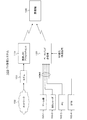
図1は、この発明の実施の形態としてのTV受信システム100の構成例を示している。このTV受信システム100は、無線LAN(Local Area Network)アクセスポイント110と、ベースバンド受信機120と、受信機140を有している。
<1. Embodiment>
[Configuration of TV reception system]
FIG. 1 shows a configuration example of a TV receiving system 100 as an embodiment of the present invention. The TV receiving system 100 includes a wireless local area network (LAN)
無線LANアクセスポイント110は、ネット系の無線データ伝送を行う。この無線LANアクセスポイント110は、モデム151を介して、インターネット等のネットワーク152に接続されている。
The wireless
無線LANアクセスポイント110には、図示しないIPTV(InternetProtocol TeleVision)事業者の配信サーバからのIPパケットが、ネットワーク152およびモデム151を介して供給される。
The wireless
図2は、IPパケットの構造を示している。IPパケットは、ヘッダ領域と、データ領域により構成されている。図2は、32ビットずつに区切って表現している。「バージョン(Version)」フィールドは、4ビット幅である。このバージョンフィールドは、IPプロトコルのバージョンを表現するために使われるフィールドである。現在は、バージョン4(IPv4)が多く使われているが、バージョン6(IPv6)への移行が進んでいる。「ヘッダ長(IHL:Internet HeaderLength)」フィールドは、4ビット幅である。このヘッダ長フィールドは、IPヘッダ部分(固定長部分+オプション部分)のサイズを表すフィールドである。 FIG. 2 shows the structure of an IP packet. An IP packet is composed of a header area and a data area. FIG. 2 is expressed by being divided into 32 bits. The “Version” field is 4 bits wide. This version field is a field used for expressing the version of the IP protocol. Currently, version 4 (IPv4) is widely used, but the transition to version 6 (IPv6) is progressing. The “Header Length (IHL)” field is 4 bits wide. This header length field is a field representing the size of the IP header portion (fixed length portion + optional portion).
「サービスタイプ(TOS:TypeOf Service)フィールドは、8ビット幅である。このサービスタイプフィールドは、IPのサービスの品質を表し、優先度、低遅延要求、高スループット要求、高信頼性要求などを指定するために使われるフィールドである。「パケット長(Total Length)」フィールドは、16ビット幅である。このパケット長フィールドは、IPパケットの全体のサイズ(オクテット長)を表すフィールドである。 “The service type (TOS: Type Of Service) field is 8 bits wide. This service type field indicates the quality of the IP service and specifies priority, low delay request, high throughput request, high reliability request, etc. The “Total Length” field is 16 bits wide. This packet length field is a field representing the entire size (octet length) of the IP packet.
「ID:Identification」フィールドは、16ビット幅である。このIDフィールドは、IPフラグメンテーションにおいて利用される、IPパケットを識別するための数値を付加するフィールドである。「フラグ(Flags)」フィールドは、3ビット幅である。このフラグフィールドは、最後か後に続くパケットがあるかどうか、パケットの分割ができるかどうかと言ったパケットの制御に関する情報を付加するフィールドである。 The “ID: Identification” field is 16 bits wide. This ID field is a field to which a numerical value for identifying an IP packet used in IP fragmentation is added. The “Flags” field is 3 bits wide. This flag field is a field for adding information on packet control, such as whether there is a packet that lasts or follows, and whether the packet can be divided.
「フラグメントオフセット(FO:Fragment Offset)」フィールドは、13ビット幅である。このフラグメントオフセットフィールドは、分割されたIPパケットが何番目かを示すシーケンス番号を付加するフィールドである。「生存時間(TTL:Time To Live)」フィールドは、8ビット幅である。この生存時間フィールドは、IPパケットがネットワークで存在できる時間を表すための数値フィールドである。 The “Fragment Offset (FO)” field is 13 bits wide. This fragment offset field is a field to which a sequence number indicating the number of the divided IP packet is added. The “Time To Live (TTL)” field is 8 bits wide. This lifetime field is a numerical field for representing the time that an IP packet can exist in the network.
「プロトコル(Protocol)」フィールドは、8ビット幅である。このプロトコルフィールドは、上位層のトランスポート層のプロトコルが何であるかを表すフィールドである。「ヘッダチェックサム(Header Checksum)」フィールドは、16ビット幅である。このヘッダチェックサムフィールドは、ヘッダ部分のチェックサム(整合性を検査するためのデータ)を表すフィールドである。 The “Protocol” field is 8 bits wide. This protocol field is a field indicating what the transport layer protocol of the upper layer is. The “Header Checksum” field is 16 bits wide. The header checksum field is a field that represents a checksum (data for checking consistency) of the header portion.
「送信元IPアドレス(Source Address)」フィールドは、32ビット幅である。この送信元IPアドレスフィールドは、送信元のIPアドレスを表すフィールドである。「送信先IPアドレス(DestinationAddress)」フィールドは、32ビット幅である。この送信先IPアドレスフィールドは、送信先のIPアドレスを表すフィールドである。ルーティング処理では、この送信先のIPアドレスを元にしてルーティング処理が行われ、送信先にIPパケットが届けられる。
The “Source Address” field is 32 bits wide. This source IP address field is a field representing the IP address of the source. The “destination IP address (Destination Address )” field is 32 bits wide. This transmission destination IP address field is a field representing the transmission destination IP address. In the routing process, a routing process is performed based on the destination IP address, and an IP packet is delivered to the destination.
「オプション(Option)」フィールドは、可変長である。このオプションフィールドは、IPパケットの送信に伴い、さまざまな付加的な機能を実現するために利用されるフィールドである。「パディング(Padding)」フィールドは、ヘッダ長が32ビットの整数倍にならない場合、0で穴埋め(パディング)して調整するフィールドである。 The “Option” field has a variable length. This optional field is a field used for realizing various additional functions in association with transmission of an IP packet. The “Padding” field is a field to be adjusted by padding with 0 when the header length does not become an integral multiple of 32 bits.
「データ(Data)」フィールドは、IPパケットとして運ばれるデータ(ペイロード)が挿入されるフィールドである。IPTVの場合、IPパケットのデータ領域(データフィールド)に挿入される映像信号は、データ圧縮された映像信号である。この圧縮方式としては、例えば、MPEG4−AVCが使用されている。 The “Data” field is a field into which data (payload) carried as an IP packet is inserted. In the case of IPTV, the video signal inserted into the data area (data field) of the IP packet is a video signal that has been subjected to data compression. As this compression method, for example, MPEG4-AVC is used.
図1に戻って、無線LANアクセスポイント110は、モデム151から供給される上述のIPパケットを含む無線信号を生成して受信機140に送信する。この実施の形態において、無線LANアクセスポイント110は、IEEE 802.11n規格に準拠した無線LAN信号を生成する。詳細説明は省略するが、このIEEE 802.11n規格は、IEEE 802.11a/gの拡張規格である。このIEEE 802.11n規格では、1次変調にOFDMを用いたOFDM_MIMO方式が採用されており、100〜600Mbpsの伝送速度で通信が可能となっている。
Returning to FIG. 1, the wireless
ベースバンド送信機120は、ベースバンド系の無線データ伝送を行う。このベースバンド送信機120には、外部機器が例えばHDMI(High-Definition Multimedia Interface)で接続されており、ベースバンド(非圧縮)の映像信号が供給される。外部機器は、例えば、ゲーム機160-1、BD(Blu-ray Disc))レコーダ160-2、PC(Personal Computer)160-3、STB(Set Top Box)160-4などである。また、ベースバンド送信機120には、図示しないアンテナで捕らえられたデジタル放送信号としてのRF信号が供給される。
The
ベースバンド送信機120は、専用パケットを生成する。この専用パケットは、IPパケットとはヘッダ領域の構成が異なるものとされる。すなわち、この専用パケットのヘッダ領域は、IPパケットのヘッダ領域にある余分な情報が取り除かれてスリム化されている。また、この専用パケットのヘッダ領域は、IP(Internet Protocol)パケットとは異なるパケットであることを識別するための識別情報を持つようにされる。また、専用パケットのデータ領域には後述するようにデータ圧縮された映像信号が挿入されるが、この専用パケットのヘッダ領域に、映像信号の圧縮方式情報を持つようにされる。
The
また、この専用パケットのデータ領域には、データ圧縮された映像信号が挿入される。すなわち、外部機器からの映像信号が受信機140に送信される場合、上述したように外部機器から供給されるベースバンド(非圧縮)の映像信号に対して、データ圧縮処理が施される。圧縮方式としては、例えば、MPEG4−AVCが使用される。この場合、専用パケットのデータ領域には、このようにデータ圧縮された映像信号が挿入される。
In addition, a data signal compressed with data is inserted into the data area of the dedicated packet. That is, when a video signal from an external device is transmitted to the
一方、放送信号に係る映像信号が受信機140に送信される場合、チューナ(放送信号処理部)からは、例えば、MPEG4−AVC、あるいはMPEG2等でデータ圧縮された映像信号が得られる。この場合、専用パケットのデータ領域には、チューナから得られるデータ圧縮された映像信号が挿入される。
On the other hand, when a video signal related to a broadcast signal is transmitted to the
図3は、専用パケットの構造の一例を示している。専用パケットは、IPパケット(図2参照)と同様に、ヘッダ領域と、データ領域により構成されている。図3は、32ビットずつに区切って表現している。 FIG. 3 shows an example of the structure of a dedicated packet. Similar to the IP packet (see FIG. 2), the dedicated packet includes a header area and a data area. FIG. 3 is expressed by being divided into 32 bits.
「バージョン(Version)」フィールドは、4ビット幅である。このバージョンフィールドは、このパケットがIPパケットとは異なるパケットであることを識別するための識別情報が配置されるフィールドである。上述のIPパケットにおいて、バージョンフィールドには、バージョン4を示す4(2進数で0010)、あるいはバージョン6を示す6(2進数で0110)の値が配置されている。この専用パケットのバージョンフィールドには、将来においてもIPパケットでは使われることのない値、例えば0〜3の値が配置される。
The “Version” field is 4 bits wide. The version field is a field which the packet is placed identification information for identifying that a different packet from the IP packet. In the above-described IP packet, a value indicating 4 (0010 in binary) or 6 (version 0110 in binary) indicating version 6 is arranged in the version field. In the version field of this dedicated packet, a value that will not be used in the IP packet in the future, for example, a value of 0 to 3 is arranged.
「コーデック(Codec)」フィールドは、3ビット幅である。このコーデックフィールドには、データ領域に挿入される圧縮映像信号の圧縮方式を示す圧縮方式情報が配置される。「パケット長(Total Length)」フィールドは、16ビット幅である。このパケット長フィールドは、専用パケットの全体のサイズ(オクテット長)を表すフィールドである。 The “Codec” field is 3 bits wide. In this codec field, compression method information indicating the compression method of the compressed video signal inserted in the data area is arranged. The “Packet Length (Total Length)” field is 16 bits wide. This packet length field is a field representing the entire size (octet length) of the dedicated packet.
「生存時間(TTL:Time To Live)」フィールドは、8ビット幅である。この生存時間フィールドは、専用パケットがネットワークで存在できる時間を表すための数値フィールドである。「送信元IPアドレス(Source Address)」フィールドは、32ビット幅である。この送信元IPアドレスフィールドは、送信元のIPアドレスを表すフィールドである。「送信先IPアドレス(DestinationAddress)」フィールドは、32ビット幅である。この送信先IPアドレスフィールドは、送信先のIPアドレスを表すフィールドである。
The “Time To Live (TTL)” field is 8 bits wide. This lifetime field is a numerical field for representing the time during which a dedicated packet can exist in the network. The “Source Address” field is 32 bits wide. This source IP address field is a field representing the IP address of the source. The “destination IP address (Destination Address )” field is 32 bits wide. This transmission destination IP address field is a field representing the transmission destination IP address.
「データ(Data)」フィールドは、専用パケットとして運ばれるデータ(ペイロード)が挿入されるフィールドである。このデータフィールドには、上述したように、外部機器から供給された映像信号、あるいは放送信号(RF信号)が処理されて得られた映像信号が挿入される。 The “Data” field is a field into which data (payload) carried as a dedicated packet is inserted. As described above, a video signal supplied from an external device or a video signal obtained by processing a broadcast signal (RF signal) is inserted into this data field.
また、ベースバンド送信機120は、上述した専用パケットを含む無線信号を生成して受信機140に送信する。この無線信号の変調方式は、上述した無線LANアクセスポイント110で生成される無線信号と同じ変調方式とされる。すなわち、この実施の形態において、ベースバンド送信機120は、上述した無線LANアクセスポイント110と同様に、IEEE 802.11n規格に準拠した無線LAN信号を生成する。
Further, the
このように、ベースバンド送信機120で生成される無線信号の変調方式が、上述した無線LANアクセスポイント110で生成される無線信号と同じ変調方式とされる。そのため、受信機140においては、単一の受信モジュールにより、ネット系とベースバンド系の双方の無線データ伝送に対処可能となる。
As described above, the modulation scheme of the radio signal generated by the
受信機140は、無線LANアクセスポイント110、あるいはベースバンド送信機120から送信されてくる無線信号、すなわちIEEE 802.11n規格に準拠した無線LAN信号を受信する。受信機140は、無線LAN信号から得られたパケット(IPパケットあるいは専用パケット)に対して、デパケタイズ処理を施して、受信映像信号を得る。また、この受信機140は、受信映像信号に対して、データ伸長処理を施して、ベースバンド(非圧縮)の映像信号を得る。
The
上述したように、ベースバンド送信機120から送られてくる無線LAN信号に含まれる専用パケットのヘッダ領域のバージョンフィールドには、IPパケットとは異なるパケットであることを識別するための識別情報が存在する。そのため、受信機140では、この識別情報に基づいて、受信された無線LAN信号から得られたパケットがIPパケットであるか専用パケットであるかの識別が可能となる。
As described above, in the version field of the header area of the dedicated packet included in the wireless LAN signal transmitted from the
受信機140では、この識別情報に基づいて、例えば、デパケタイズ処理において、IPパケットと専用パケットとでは、ヘッダ処理が変えられる。上述したように、専用パケットのヘッダ領域は、IPパケットに比べてスリム化されているので、受信された無線LAN信号から得られたパケットが専用パケットである場合には、IPパケットを処理する場合に比べて処理の高速化が図られる。
In the
また、受信機140では、受信された無線LAN信号から得られたパケットが専用パケットである場合、そのパケットのヘッダ領域には、映像信号の圧縮方式情報が存在する。したがって、上述の受信映像信号のデータ伸長処理はこの圧縮方式情報に基づいて行われ、受信映像信号のデータ伸長処理が適切に行われる。
In the
[ベースバンド送信機、受信機の構成例]
図4は、ベースバンド送信機120の構成例を示している。ベースバンド送信機120は、制御部121と、ユーザ操作部122と、表示部123を有している。また、このベースバンド送信機120は、HDMI端子124と、HDMI受信部125と、エンコーダ126を有している。また、このベースバンド送信機120は、アンテナ端子127と、チューナ128と、スイッチ部129と、パケット化部130と、無線LANモジュール131と、送信アンテナ132を有している。
[Configuration example of baseband transmitter and receiver]
FIG. 4 shows a configuration example of the
制御部121は、CPU(CentralProcessing Unit)を備えており、ベースバンド送信機120の各部の動作を制御する。ユーザ操作部122および表示部123は、ユーザインタフェースを構成し、制御部121に接続されている。ユーザ操作部122は、ベースバンド送信機120の図示しない筐体に配置されたキー、釦、ダイアル、あるいは表示部123の表示面に配置されたタッチパネル等で構成される。表示部123は、LCD(Liquid Crystal Display)等の表示パネルで構成される。
The
HDMI受信部125は、HDMI端子124に接続されている。このHDMI受信部125は、HDMIに準拠した通信により、図示しないHDMIケーブルを介して接続されているゲーム機160-1等の外部機器から一方向に送信されてくるベースバンド(非圧縮)の映像信号を受信する。HDMI端子124およびHDMI受信部125は、映像信号受信部を構成している。
The
エンコーダ126は、HDMI受信部125で受信された映像信号にデータ圧縮処理を施して、データ圧縮処理された送信映像信号を得る。ここで、送信映像信号の圧縮方式として所定の圧縮方式、例えば、従来周知の符号化効率のよいMPEG4−AVCが採用される。なお、このMPEG4−AVCでは、ブロック単位で符号化が行われる。また、このMPEG4−AVCでは、ブロック単位で動き補償した予測残差が抽出されることで、フレーム間の冗長が取り除かれる。また、このMPEG4−AVCでは、空間軸では、ブロックベースの直交変換および可変長符号化が行われ、フレーム内の冗長が取り除かれる。エンコーダ126は、データ圧縮部を構成している。
The
チューナ128は、アンテナ端子127に接続された図示しないアンテナで捕らえられたデジタル放送信号を処理して、所定番組の映像信号を得る。この映像信号は、MPEG2、あるいはMPEG4−AVC等の圧縮方式によってデータ圧縮された映像信号である。チューナ126は、放送信号処理部を構成している。
The
スイッチ部129は、エンコーダ126で得られた映像信号、またはチューナ128で得られた映像信号を、送信映像信号として選択的に取り出す。このスイッチ部129の制御は、ユーザのユーザ操作部122からの選択操作に基づいて、制御部121により行われる。
The
パケット化部130は、上述した専用パケット(図3参照)を生成する。この専用パケットは、上述したように、バージョンフィールドに格納される値が0〜3とされ、このパケットがIPパケットとは異なるパケットであることが識別可能とされている。パケット化部130は、この専用パケットのデータ領域に、スイッチ部129で取り出された映像信号を挿入する。
The
また、パケット化部130は、専用パケットのヘッダ領域に設けられたコーデックフィールドに、スイッチ部129で取り出された映像信号が如何なる圧縮方式で圧縮されたものであるかを示す圧縮方式情報を格納する。例えば、映像信号がMPEG4−AVCでデータ圧縮されている場合、圧縮方式情報はMPEG4−AVCを示す情報となる。また、例えば、映像信号がMPEG2でデータ圧縮されている場合、圧縮方式情報はMPEG2を示す情報となる。
Further, the
無線LANモジュール131は、送信部および受信部を含んでおり、所定の通信プロトコルに準拠して送信処理および受信処理を行う。この無線モジュール131は、例えば、無線LANの方式としてIEEE 802.11n規格に対応している。この無線LANモジュール131は、パケット化部130で生成された専用パケットを含む無線LAN信号を生成して、アンテナ132を通じて受信機140に送信する。無線LANモジュール131は、無線送信部を構成している。
The
図4に示すベースバンド送信機120の送信動作を説明する。
A transmission operation of the
ゲーム機160-1等の外部機器からHDMIケーブルを介して供給されるベースバンド(非圧縮)の映像信号はHDMI受信部125で受信され、エンコーダ126に供給される。このエンコーダ126では、ベースバンドの映像信号に対して、例えばMPEG4−AVC等の圧縮方式でデータ圧縮処理が施される。このエンコーダ126で得られたデータ圧縮されている映像信号は、スイッチ部129に供給される。
A baseband (uncompressed) video signal supplied from an external device such as the game machine 160-1 via the HDMI cable is received by the
また、図示しないアンテナで捕らえられたデジタル放送信号(RF信号)は、アンテナ端子127からチューナ128に供給される。このチューナ128では、デジタル放送信号が処理されて、ユーザの選局操作に応じた所定番組の映像信号が得られる。この映像信号は、例えば、MPEG2、あるいはMPEG4−AVC等の圧縮方式でデータ圧縮されている映像信号である。このチューナ128で得られたデータ圧縮されている映像信号は、スイッチ部129に供給される。
A digital broadcast signal (RF signal) captured by an antenna (not shown) is supplied from the
スイッチ部129では、ユーザの選択操作に応じて、エンコーダ126で得られた外部機器の出力映像信号、またはチューナ126で得られた放送映像信号が、送信映像信号として選択的に取り出される。このスイッチ部129で取り出された映像信号は、パケット化部130に供給される。
In the
パケット化部130では、スイッチ部129から供給されるデータ圧縮された映像信号がデータ領域に挿入され、ヘッダ領域にパケット識別情報および圧縮方式情報を持つ専用パケット(図3参照)が生成される。このようにパケット化部130で生成された専用パケットは、無線LANモジュール131に供給される。
In the
無線LANモジュール131では、所定の通信プロトコルに準拠して、専用パケットの送信処理が行われる。すなわち、この無線LANモジュール131では、例えば、IEEE 802.11n規格に対応して、専用パケットを含む無線LAN信号が生成され、アンテナ132から送信される。
In the
図5は、受信機140の構成例を示している。この受信機140は、制御部141と、ユーザ操作部142を有している。また、受信機140は、アンテナ143と、無線LANモジュール144と、デパケット化部145と、デコーダ146と、表示処理部147と、表示パネル148を有している。
FIG. 5 shows a configuration example of the
制御部141は、CPU(CentralProcessing Unit)を備えており、受信機140の各部の動作を制御する。ユーザ操作部142は、ユーザインタフェースを構成し、制御部141に接続されている。ユーザ操作部142は、受信機140の図示しない筐体に配置されたキー、釦、ダイアル、あるいはリモコン等で構成される。
The
無線LANモジュール144は、送信部および受信部を含んでおり、所定の通信プロトコルに準拠して送信処理および受信処理を行う。この無線モジュール144は、例えば、無線LANの方式としてIEEE 802.11n規格に対応している。この無線LANモジュール144は、無線LANアクセスポイント110、あるいはベースバンド送信機120から送信された無線LAN信号を、アンテナ143を通じて受信する。
The
そして、この無線LANモジュール144は、受信された無線LAN信号に含まれる、データ領域に映像信号が挿入されたパケットを取得する。このパケットは、受信無線LAN信号が無線LANアクセスポイント110からのものであるときはIPパケット(図2参照)である。また、このパケットは、受信無線LAN信号がベースバンド送信機120からのものであるときは専用パケット(図3参照)である。無線LANモジュール144は、無線受信部を構成している。
Then, the
デパケット化部145は、無線LANモジュール144で得られたパケットに対して、デパケタイズ処理を行って受信映像信号を得る。制御部141は、無線LANモジュール144で得られたパケットのヘッダ領域の先頭にあるバージョンフィールドの値(識別情報)に基づいて、IPパケットであるか専用パケットであるかを識別する。そして、制御部141は、この識別結果に基づいて、デパケット化部145の動作を、IPパケットと専用パケットとでは変化させる。ここで、制御部141は、パケット識別部およびデパケット化制御部を構成している。
The
この場合、デパケット化部145のデパケタイズ処理において、IPパケットと専用パケットでは、ヘッダ処理が変えられる。上述したように、専用パケットのヘッダ領域は、IPパケットに比べてスリム化されているので、受信された無線LAN信号から得られたパケットが専用パケットである場合には、IPパケットを処理する場合に比べて処理の高速化が図られる。
In this case, in the depacketizing process of the
デコーダ146は、デパケット化部145で得られた受信映像信号に対してデータ伸長処理を施して、ベースバンド(非圧縮)の映像信号を得る。制御部141は、無線LANモジュール144で得られたパケットが専用パケットであるとき、そのコーデックフィールドに格納されている圧縮方式情報を取得する。制御部141は、IPパケットであるか専用パケットであるか、また、専用パケットであるときは取得した圧縮方式情報に基づいて、デコーダ146の動作を制御する。デコーダ146は、データ伸長部を構成している。
The
すなわち、無線LANモジュール144で得られたパケットがIPパケットであるとき、デコーダ146では、所定の圧縮方式、例えばMPEG4−AVCに対応したデータ伸長処理が行われる。これに対して、無線LANモジュール144で得られたパケットが専用パケットであるときは、デコーダ146では、圧縮方式情報が示す圧縮方式に対応したデータ伸長処理が行われ、データ伸長処理が適切に行われる。
That is, when the packet obtained by the
表示処理部147は、デコーダ146で得られたベースバンドの映像信号に対して、色調整、輪郭強調、グラフィックスデータの重畳等の処理を行う。表示パネル148は、表示処理部147で処理された映像信号に画像を表示する。表示パネル148は、例えば、LCD(Liquid Crystal Display)、有機EL(ElectroLuminescence)、PDP(Plasma Display Panel)等で構成される。
The
図5に示す受信機140の受信動作を説明する。無線LANアクセスポイント110、あるいはベースバンド送信機120から送信された無線LAN信号は、アンテナ143を通じて無線LANモジュール144で受信される。そして、この無線LANモジュール144では、受信された無線LAN信号に含まれるパケット(IPパケット、専用パケット)が取得される。このパケットはデパケット化部145に供給される。
A reception operation of the
デパケット化部145では、無線LANモジュール144で得られたパケットに対して、デパケタイズ処理が行われて受信映像信号が得られる。上述したように、IPパケットあるいは専用パケットのデータ領域に挿入された映像信号はデータ圧縮された映像信号であることから、この受信映像信号はデータ圧縮された映像信号である。
In the
無線LANモジュール144で得られたパケットのヘッダ領域の先頭にあるバージョンフィールドの値は、IPパケットの場合は4または6であり、専用パケットの場合は例えば0〜3のいずれかとされている。そのため、制御部141では、このバージョンフィールドの値を識別情報として、無線アクセスポイント110からのIPパケットであるか、ベースバンド送信機120からの専用パケットであるかが識別される。
The value of the version field at the head of the header area of the packet obtained by the
この識別結果に基づき、制御部141により、デパケット化部145の動作が制御される。すなわち、上述したようにIPパケットと専用パケットとではヘッダ領域の構造を異にしているため、ヘッダ処理が変えられる。上述したように、専用パケットのヘッダ領域は、IPパケットに比べてスリム化されているので、専用パケットのヘッダ処理に要する時間は、IPパケットのヘッダ処理に比べて短くて済む。そのため、デパケット化部145のデパケタイズ処理による遅延は、専用パケットの場合、IPパケットの場合に比べて短くなる。
Based on the identification result, the
デパケット化部145で得られた受信映像信号はデコーダ146に供給される。このデコーダ146では、データ伸長処理が施されて、ベースバンド(非圧縮)の映像信号が得られる。無線LANモジュール144で得られたパケットが専用パケットの場合、ヘッダ領域のバージョンフィールドに続くコーデックフィールドに、この専用パケットのデータ領域に挿入された映像信号の圧縮方式を示す圧縮方式情報が格納されている。そのため、制御部141では、このコーデックフィールドの圧縮方式情報により、デパケット化部145で得られた受信映像信号の圧縮方式が認識される。
The received video signal obtained by the
上述のパケットの識別結果およびこの圧縮方式が認識結果に基づいて、制御部141により、デコーダ146におけるデータ伸長処理が制御される。すなわち、無線LANモジュール144で得られたパケットがIPパケットであるとき、デコーダ146では、受信映像信号に対して所定の圧縮方式、例えばMPEG4−AVCに対応したデータ伸長処理が行われる。これに対して、無線LANモジュール144で得られたパケットが専用パケットであるときは、デコーダ146では、受信映像信号に対して、圧縮方式情報が示す圧縮方式に対応したデータ伸長処理が行われ、データ伸長処理が適切に行われる。
Based on the packet identification result and the compression result, the
デコーダ146で得られたベースバンド(非圧縮)の映像信号は、表示処理部147に供給される。この表示処理部147では、この映像信号に対して、ユーザ操作、あるいは自動的に、色調整、輪郭強調、グラフィックスデータの重畳等の処理が行われる。そして、このように表示処理部147で処理された映像信号は表示パネル148に供給され、この表示パネル148に受信映像信号による画像が表示される。
The baseband (uncompressed) video signal obtained by the
上述したように、図1に示すTV受信システム100において、データベース送信機120から受信機140に送信される無線信号は、無線LANアクセスポイント110から受信機140に送信される無線信号と変調方式が同じものとされる。すなわち、データベース送信機120から受信機140に送信される無線信号は、例えば、IEEE 802.11n規格に準拠した無線LAN信号とされる。そのため、受信機140では、単一の無線受信モジュール(無線LANモジュール144)により、ネット系とベースバンド系の双方の無線データ伝送に対処できる。したがって、受信機140の構成が簡単となり、そのコスト低減を図ることができる。
As described above, in the TV reception system 100 shown in FIG. 1, the radio signal transmitted from the
また、図1に示すTV受信システム100において、ベースバンド送信機120では、データ領域に送信映像信号が挿入された専用パケットが生成され、この専用パケットが含まれた無線信号が受信機140に送信される。この専用パケットは、IPパケットに比べて、そのヘッダ領域がスリム化されていると共に、そのバージョンフィールドに格納された値によりIPパケットとは異なるパケットであることが識別される構造となっている。そのため、受信機140においては、専用パケットとIPパケットとを自動的に識別できる。従って、専用パケットに関してはIPパケットとは異なるヘッダ処理を行うことができ、デパケタイズ処理に要する時間を短くでき、ベースバンド系の無線データ伝送の伝送遅延を抑制できる。
In the TV reception system 100 shown in FIG. 1, the
また、図1に示すTV受信システム100において、ベースバンド送信機120では、データ領域に送信映像信号が挿入された専用パケットが生成され、この専用パケットが含まれた無線信号が受信機140に送信される。この専用パケットのデータ領域にコーデックフィールドが設けられ、データ領域に挿入されている映像信号の圧縮方式を示す圧縮方式情報が格納されている。そのため、受信機140において、無線LANモジュール144で得られたパケットが専用パケットであるとき、デコーダ146では、この圧縮方式情報に基づいて、データ伸長処理の処理方式を変更でき、受信映像信号のデータ伸長を適切に行うことができる。
In the TV reception system 100 shown in FIG. 1, the
<2.変形例>
なお、上述実施の形態において、データベース送信機120で生成される専用パケットは、図3に示す構造例に限定されるものではなく、その他の構造であってもよい。要は、データ領域が余分な情報が含まれないようにスリム化され、しかも、このデータ領域にIPパケットとは異なるパケットであることを示す識別情報が含まれていればよい。なお、データ領域に挿入される映像信号の圧縮方式が固定であれば、専用パケットのヘッダ領域に圧縮方式情報を持つ必要はない。
<2. Modification>
In the above-described embodiment, the dedicated packet generated by the
上述実施の形態において、受信機140は、無線LANアクセスポイント110からのIPパケットとベースバンド送信機120からの専用のパケットを識別して、デパケット化部145のデパケタイズ処理におけるヘッダ処理を自動的に変更するものを示した。上述していないが、受信機140では、IPパケットと専用パケットの識別結果を用いていずれかを受信可能とする受信制限機能などを設けることも可能となる。
In the above embodiment, the
また、上述実施の形態においては、ゲーム機160-1等の外部機器からのベースバンド(非圧縮)の映像信号がベースバンド送信機120に供給される構成であるが、ゲーム機160-1等に、ベースバンド送信機120が内蔵された一体的な構成も考えられる。
In the above-described embodiment, a baseband (uncompressed) video signal from an external device such as the game machine 160-1 is supplied to the
また、上述実施していないが、ベースバンド送信機120において、複数の外部機器からの映像信号がデータ領域に挿入された専用パケットを時分割的に生成して受信機140に送ることも考えられる。その場合、専用パケットのヘッダ領域には各外部機器を識別する情報を格納するフィールドが設けられ、受信機140では、その識別情報を用いて、各外部機器の映像信号を選択的に受信可能としてもよい。
Although not implemented above, the
この発明は、受信機の構成を簡単にでき、そのコスト低減を図ることができるものであり、ネット系とベースバンド系の双方に対応したTV受信システム等に適用できる。 The present invention can simplify the configuration of the receiver and reduce the cost thereof, and can be applied to a TV receiving system and the like corresponding to both a network system and a baseband system.
100・・・TV受信システム、110・・・無線LANアクセスポイント、120・・・ベースバンド送信機、121・・・制御部、122・・・ユーザ操作部、123・・・表示部、124・・・HDMI端子、125・・・HDMI受信部、126・・・エンコーダ、127・・・アンテナ端子、128・・・チューナ、129・・・スイッチ部、130・・・パケット化部、131・・・無線LANモジュール、132・・・アンテナ、140・・・受信機、141・・・制御部、142・・・ユーザ操作部、143・・・アンテナ、144・・・無線LANモジュール、145・・・デパケット化部、146・・・デコーダ、147・・・表示処理部、148・・・表示パネル、151・・・モデム、152・・・ネットワーク、160-1・・・ゲーム機、160-2・・・BDレコーダ、160-3・・・PC、160-4・・・STB
DESCRIPTION OF SYMBOLS 100 ... TV receiving system, 110 ... Wireless LAN access point, 120 ... Baseband transmitter, 121 ... Control part, 122 ... User operation part, 123 ... Display part, 124. .. HDMI terminal, 125... HDMI receiving unit, 126... Encoder, 127... Antenna terminal, 128 .. tuner, 129... Switch unit, 130.
Claims (12)
上記パケット化部で生成された専用パケットを含む無線信号を生成して送信する無線送信部を備え、
上記専用パケットのヘッダ領域の先頭にはIPパケットのヘッダ領域の先頭のバージョンフィールドと同じビット幅のバージョンフィールドが設けられ、該専用パケットのバージョンフィールドには上記IPパケットのバージョンフィールドに配置される値とは異なる値が配置される
無線送信機。 Transmitting the video signal to the data region is inserted, and a packetizing unit to generate a dedicated packet for transmitting the transmission video signal,
A wireless transmission unit that generates and transmits a wireless signal including the dedicated packet generated by the packetization unit ,
A version field having the same bit width as the first version field of the header area of the IP packet is provided at the head of the header area of the dedicated packet, and the value placed in the version field of the IP packet is included in the version field of the dedicated packet. radio transmitter that will be located a different value from the.
上記パケット化部で生成される専用パケットのヘッダ領域に、上記送信映像信号の圧縮方式情報を持つ
請求項1に記載の無線送信機。 The transmission video signal is a data-compressed video signal,
The wireless transmitter according to claim 1, wherein the transmission video signal has compression scheme information in a header area of a dedicated packet generated by the packetization unit.
請求項2に記載の無線送信機。 The wireless transmitter according to claim 2, wherein the wireless signal generated and transmitted by the wireless transmission unit is a wireless LAN signal conforming to the IEEE 802 / 11n standard.
請求項3に記載の無線送信機。 The wireless transmitter according to claim 3, wherein the compression method of the transmission video signal is MPEG4-AVC or MPEG2.
上記映像信号受信部で受信された映像信号にデータ圧縮処理を施して上記データ圧縮された送信映像信号を得るデータ圧縮部をさらに備える
請求項2に記載の無線送信機。 A video signal receiver for receiving an uncompressed video signal from an external device;
The wireless transmitter according to claim 2, further comprising: a data compression unit that performs a data compression process on the video signal received by the video signal receiving unit to obtain the data-compressed transmission video signal.
請求項2に記載の無線送信機。 The wireless transmitter according to claim 2, further comprising a broadcast signal processing unit that processes a broadcast signal and obtains the data-compressed transmission video signal.
上記パケット化ステップで生成された専用パケットを含む無線信号を生成して送信する無線送信ステップを備え、
上記専用パケットのヘッダ領域の先頭にはIPパケットのヘッダ領域の先頭のバージョンフィールドと同じビット幅のバージョンフィールドが設けられ、該専用パケットのバージョンフィールドには上記IPパケットのバージョンフィールドに配置される値とは異なる値が配置される
無線送信方法。 Transmitting the video signal to the data region is inserted, and packetization step of generating a dedicated packet for transmitting the transmission video signal,
A wireless transmission step of generating and transmitting a wireless signal including the dedicated packet generated in the packetizing step ,
A version field having the same bit width as the first version field of the header area of the IP packet is provided at the head of the header area of the dedicated packet, and the value placed in the version field of the IP packet is included in the version field of the dedicated packet. radio transmission method that will be located a different value from the.
上記無線受信部で得られたパケットを処理して受信映像信号を得るデパケット化部と、
上記無線受信部で得られたパケットが送信映像信号を送信するための専用パケットであるかIPパケットであるかを識別するパケット識別部と、
上記パケット識別部の識別結果に応じて上記デパケット化部の処理を制御するデパケット化制御部を備え、
上記パケット識別部は、上記パケットのヘッダ領域の先頭に設けられたバージョンフィールドの値に基づいて上記専用パケットであるかIPパケットであるかを識別する
無線受信機。 A radio reception unit that receives a radio signal including a packet in which a video signal is inserted in a data area, and obtains the packet from the radio signal;
A depacketizer for processing a packet obtained by the wireless receiver to obtain a received video signal;
A packet identification unit for identifying whether the packet obtained by the wireless reception unit is a dedicated packet or an IP packet for transmitting a transmission video signal ;
A depacketization control unit that controls processing of the depacketization unit according to the identification result of the packet identification unit ,
The packet identification unit, a radio receiver that identifies whether an IP packet or an above-only packets based on the value of the version field provided in the beginning of the header region of the packet.
上記専用パケットのヘッダ領域に、上記映像信号の圧縮方式情報を持ち、
上記デパケット化部で得られた受信映像信号にデータ伸長処理を施して非圧縮の映像信号を得るデータ伸長部と、
上記パケット識別部の識別結果により上記無線受信部で得られたパケットが上記専用パケットであるとき、上記データ伸長部のデータ伸長処理を、該専用パケットのヘッダ領域に持つ上記圧縮方式情報に基づいて制御するデータ伸長制御部をさらに備える
請求項8に記載の無線受信機。 The video signal inserted into the data area of the packet is a data-compressed video signal,
In the header area of the dedicated packet has the compression method information of the video signal,
A data decompression unit that performs a data decompression process on the received video signal obtained by the depacketization unit to obtain an uncompressed video signal;
When the packet obtained by the wireless reception unit based on the identification result of the packet identification unit is the dedicated packet, the data decompression processing of the data decompression unit is performed based on the compression method information included in the header area of the dedicated packet. The radio receiver according to claim 8, further comprising a data decompression control unit to control.
請求項9に記載の無線受信機。 The wireless receiver according to claim 9, wherein the wireless signal received by the wireless receiving unit is a wireless LAN signal compliant with the IEEE 802 / 11n standard.
請求項10に記載の無線受信機。 The wireless receiver according to claim 10, wherein a compression method of the video signal inserted in the data area of the dedicated packet is MPEG4-AVC or MPEG2.
上記無線受信ステップで得られたパケットを処理して受信映像信号を得るデパケット化ステップと、
上記無線受信ステップで得られたパケットが送信映像信号を送信するための専用パケットであるかIPパケットであるかを識別するパケット識別ステップと、
上記パケット識別ステップの識別結果に応じて上記デパケット化ステップの処理を制御するデパケット化制御ステップを備え、
上記パケット識別ステップでは、上記パケットのヘッダ領域の先頭に設けられたバージョンフィールドの値に基づいて上記専用パケットであるかIPパケットであるかを識別する
無線受信方法。 A radio reception step of receiving a radio signal including a packet in which a video signal is inserted in a data area and obtaining the packet from the radio signal;
A depacketizing step of processing the packet obtained in the wireless reception step to obtain a received video signal;
A packet identification step for identifying whether the packet obtained in the wireless reception step is a dedicated packet or an IP packet for transmitting a transmission video signal ;
A depacketization control step for controlling the processing of the depacketization step according to the identification result of the packet identification step ,
In the above packet identification step, the radio receiving method based on the value of the version field provided in the beginning of the header region of the packet that identifies whether the IP packet whether the above special packet.
Priority Applications (3)
| Application Number | Priority Date | Filing Date | Title |
|---|---|---|---|
| JP2009101546A JP5332854B2 (en) | 2009-04-20 | 2009-04-20 | Wireless transmitter, wireless transmission method, wireless receiver, and wireless reception method |
| US12/798,202 US8837442B2 (en) | 2009-04-20 | 2010-03-31 | Wireless transmitter, wireless transmission method, wireless receiver and wireless reception method |
| CN2010101644703A CN101895745B (en) | 2009-04-20 | 2010-04-13 | Wireless transmitter, wireless transmission method, wireless receiver and wireless reception method |
Applications Claiming Priority (1)
| Application Number | Priority Date | Filing Date | Title |
|---|---|---|---|
| JP2009101546A JP5332854B2 (en) | 2009-04-20 | 2009-04-20 | Wireless transmitter, wireless transmission method, wireless receiver, and wireless reception method |
Publications (3)
| Publication Number | Publication Date |
|---|---|
| JP2010252205A JP2010252205A (en) | 2010-11-04 |
| JP2010252205A5 JP2010252205A5 (en) | 2012-05-17 |
| JP5332854B2 true JP5332854B2 (en) | 2013-11-06 |
Family
ID=42980935
Family Applications (1)
| Application Number | Title | Priority Date | Filing Date |
|---|---|---|---|
| JP2009101546A Expired - Fee Related JP5332854B2 (en) | 2009-04-20 | 2009-04-20 | Wireless transmitter, wireless transmission method, wireless receiver, and wireless reception method |
Country Status (3)
| Country | Link |
|---|---|
| US (1) | US8837442B2 (en) |
| JP (1) | JP5332854B2 (en) |
| CN (1) | CN101895745B (en) |
Families Citing this family (9)
| Publication number | Priority date | Publication date | Assignee | Title |
|---|---|---|---|---|
| US9066154B2 (en) * | 2009-11-13 | 2015-06-23 | Triveni Digital, Inc. | System and method for enhanced television and delivery of enhanced television content |
| JP5221704B2 (en) * | 2011-04-19 | 2013-06-26 | シャープ株式会社 | VIDEO REPRODUCTION DEVICE, VIDEO TRANSMISSION DEVICE, VIDEO REPRODUCTION PROGRAM, VIDEO TRANSMISSION PROGRAM, AND RECORDING MEDIUM |
| JP5869236B2 (en) | 2011-06-03 | 2016-02-24 | 任天堂株式会社 | Information processing program, information processing apparatus, information processing system, and information processing method |
| JP5937792B2 (en) * | 2011-06-03 | 2016-06-22 | 任天堂株式会社 | GAME PROGRAM, GAME DEVICE, GAME SYSTEM, AND GAME PROCESSING METHOD |
| US9485687B2 (en) * | 2013-02-15 | 2016-11-01 | Exalt Wireless, Inc. | Selective compression in a wireless communication system |
| WO2016178417A1 (en) | 2015-05-07 | 2016-11-10 | 株式会社 東芝 | Wireless communication device |
| WO2016178418A1 (en) * | 2015-05-07 | 2016-11-10 | 株式会社 東芝 | Wireless communication terminal and wireless communication method |
| CN107925516A (en) * | 2016-02-03 | 2018-04-17 | 华为技术有限公司 | Data transmission method and device |
| EP3273424B1 (en) * | 2016-07-21 | 2019-03-13 | The Boeing Company | System and method of aircraft surveillance and tracking |
Family Cites Families (60)
| Publication number | Priority date | Publication date | Assignee | Title |
|---|---|---|---|---|
| US5289276A (en) * | 1992-06-19 | 1994-02-22 | General Electric Company | Method and apparatus for conveying compressed video data over a noisy communication channel |
| US5461619A (en) * | 1993-07-06 | 1995-10-24 | Zenith Electronics Corp. | System for multiplexed transmission of compressed video and auxiliary data |
| WO1998042132A1 (en) * | 1997-03-17 | 1998-09-24 | Matsushita Electric Industrial Co., Ltd. | Method of processing, transmitting and receiving dynamic image data and apparatus therefor |
| US5832085A (en) * | 1997-03-25 | 1998-11-03 | Sony Corporation | Method and apparatus storing multiple protocol, compressed audio video data |
| US6335935B2 (en) * | 1998-07-08 | 2002-01-01 | Broadcom Corporation | Network switching architecture with fast filtering processor |
| EP1269695B1 (en) * | 2000-03-31 | 2008-07-02 | BRITISH TELECOMMUNICATIONS public limited company | Communications network |
| US7046605B1 (en) * | 2000-06-28 | 2006-05-16 | Samsung Electronics Co., Ltd. | Recording medium for storing version information for maintaining recording and/or reproducing compatibility, and method and apparatus for managing the same |
| DE60018927T2 (en) * | 2000-09-07 | 2005-07-28 | Matsushita Electric Industrial Co. Ltd., Kadoma | Method and apparatus for data packet transmission |
| US6934756B2 (en) * | 2000-11-01 | 2005-08-23 | International Business Machines Corporation | Conversational networking via transport, coding and control conversational protocols |
| US20020103925A1 (en) * | 2000-12-06 | 2002-08-01 | Sheth Siddharth C. | Generic programmable internet protocol classification technique for a broadband engine |
| NO315887B1 (en) * | 2001-01-04 | 2003-11-03 | Fast Search & Transfer As | Procedures for transmitting and socking video information |
| US20020152467A1 (en) * | 2001-02-12 | 2002-10-17 | Rosario Fiallos | Automated generation of conditional access packets for IRD upgrades via radio frequency software download in satellite television systems |
| US7778281B2 (en) * | 2001-04-27 | 2010-08-17 | Panasonic Corporation | Wireless communication apparatus |
| US20020163908A1 (en) * | 2001-05-07 | 2002-11-07 | Ari Lakaniemi | Apparatus, and associated method, for synchronizing operation of codecs operable pursuant to a communicaton session |
| US20020181400A1 (en) * | 2001-05-30 | 2002-12-05 | Nokia Corporation | Method of communicating a flow of data packets across a network |
| KR100434270B1 (en) * | 2001-05-30 | 2004-06-04 | 엘지전자 주식회사 | Control System for Home Appliance Network |
| US7747853B2 (en) * | 2001-06-06 | 2010-06-29 | Sony Corporation | IP delivery of secure digital content |
| US7151749B2 (en) * | 2001-06-14 | 2006-12-19 | Microsoft Corporation | Method and System for providing adaptive bandwidth control for real-time communication |
| US7170893B2 (en) * | 2001-06-15 | 2007-01-30 | Lucent Technologies Inc. | Technique for selecting the number of packets to be concatenated |
| WO2003017577A1 (en) * | 2001-08-09 | 2003-02-27 | Matsushita Electric Industrial Co., Ltd. | Transmission apparatus and transmission method |
| US7124202B2 (en) * | 2001-11-13 | 2006-10-17 | Intel Corporation | System and method for aggregating channel segment ID's into a first section and data segments into a second section |
| JP2003162462A (en) * | 2001-11-26 | 2003-06-06 | Toshiba Corp | Communication network system |
| JP3912091B2 (en) * | 2001-12-04 | 2007-05-09 | ソニー株式会社 | Data communication system, data transmission apparatus, data reception apparatus and method, and computer program |
| US7599360B2 (en) * | 2001-12-26 | 2009-10-06 | Cisco Technology, Inc. | Methods and apparatus for encapsulating a frame for transmission in a storage area network |
| KR100840733B1 (en) * | 2002-01-05 | 2008-06-24 | 엘지전자 주식회사 | Method and system for processing packet data in a communications system and receiving unit thereof |
| ATE377314T1 (en) * | 2002-07-04 | 2007-11-15 | Nokia Corp | MANAGEMENT OF A PACKET SWITCHED CONFERENCE CIRCUIT |
| US7047001B2 (en) * | 2002-12-02 | 2006-05-16 | Qualcomm Inc. | Method and apparatus for mobile-terminated short data burst communication |
| KR100464336B1 (en) * | 2002-12-28 | 2005-01-03 | 삼성전자주식회사 | Method of Advertising VOD Service for Mobile Terminal |
| JP3795018B2 (en) * | 2003-01-20 | 2006-07-12 | 富士通株式会社 | Streaming transmission method, streaming transmission system, data processing apparatus, and computer program |
| CN1531282A (en) * | 2003-03-12 | 2004-09-22 | ���µ�����ҵ��ʽ���� | Packet trunk device |
| KR100596755B1 (en) * | 2003-05-30 | 2006-07-04 | 엘지전자 주식회사 | Home network system |
| KR100638030B1 (en) * | 2003-05-30 | 2006-10-23 | 엘지전자 주식회사 | Network electric device |
| US7245879B2 (en) * | 2003-08-08 | 2007-07-17 | Intel Corporation | Apparatus and associated methods to perform intelligent transmit power control with subcarrier puncturing |
| KR101024904B1 (en) * | 2003-08-14 | 2011-03-31 | 엘지전자 주식회사 | Recording medium,recording method, recording apparatus and recording/reproducing system |
| US20050071375A1 (en) * | 2003-09-30 | 2005-03-31 | Phil Houghton | Wireless media player |
| JP4212456B2 (en) * | 2003-11-18 | 2009-01-21 | 株式会社東芝 | Optical disc, optical disc apparatus and reproducing method |
| US7430617B2 (en) * | 2003-12-19 | 2008-09-30 | Nokia Corporation | Method and system for header compression |
| CN1957559A (en) * | 2004-05-27 | 2007-05-02 | Lg电子株式会社 | Home network system |
| US8630305B2 (en) * | 2004-06-04 | 2014-01-14 | Qualcomm Incorporated | High data rate interface apparatus and method |
| US7483376B2 (en) * | 2004-06-17 | 2009-01-27 | International Business Machines Corporation | Method and apparatus for discovering path maximum transmission unit (PMTU) |
| CN1885914A (en) * | 2005-06-21 | 2006-12-27 | 海尔集团公司 | Transmitter and receiver for wireless high-definition television signal |
| US20060291468A1 (en) * | 2005-06-22 | 2006-12-28 | Rajendra Bopardikar | Selective re-transmission of lost multi-media data packets |
| US7961739B2 (en) * | 2005-07-21 | 2011-06-14 | Genband Us Llc | Systems and methods for voice over multiprotocol label switching |
| JP2007049242A (en) | 2005-08-05 | 2007-02-22 | Sony Corp | Wireless transmission system and wireless transmission method |
| JP2008109711A (en) * | 2006-02-10 | 2008-05-08 | Matsushita Electric Ind Co Ltd | Radio communication system |
| CA2655500A1 (en) * | 2006-06-19 | 2007-12-27 | Liquid Computing Corporation | Token based flow control for data communication |
| US8102853B2 (en) * | 2006-08-09 | 2012-01-24 | Samsung Electronics Co., Ltd. | System and method for wireless communication of uncompressed video having fixed size MAC header with an extension |
| JP2008048119A (en) * | 2006-08-15 | 2008-02-28 | Nippon Hoso Kyokai <Nhk> | Radio terminal device |
| US8306063B2 (en) * | 2006-08-29 | 2012-11-06 | EXFO Services Assurance, Inc. | Real-time transport protocol stream detection system and method |
| US20080186971A1 (en) * | 2007-02-02 | 2008-08-07 | Tarari, Inc. | Systems and methods for processing access control lists (acls) in network switches using regular expression matching logic |
| US7877514B2 (en) * | 2007-05-03 | 2011-01-25 | Samsung Electronics Co., Ltd. | System and method for time-constrained transmission of video in a communication system |
| KR20080102768A (en) * | 2007-05-22 | 2008-11-26 | 삼성전자주식회사 | Method for generating packet in wireless hdmi cec |
| CN101785302B (en) * | 2007-08-24 | 2013-07-17 | Lg电子株式会社 | Digital broadcasting system and method of processing data in digital broadcasting system |
| CN101394490A (en) * | 2007-09-20 | 2009-03-25 | 厦门华侨电子股份有限公司 | Non-compressed transmitting and receiving integrated display device for wireless digital high resolution audio and video signal |
| WO2009038406A2 (en) * | 2007-09-21 | 2009-03-26 | Lg Electronics Inc. | Digital broadcasting system and data processing method |
| FR2924887B1 (en) * | 2007-12-07 | 2011-07-15 | Thales Sa | METHOD AND DEVICE FOR ROBUST TRANSMISSION OF COMPRESSED NETWORK HEADERS |
| CN101202920B (en) * | 2007-12-19 | 2010-06-23 | 北京创毅视讯科技有限公司 | Data sending, transmission method, launching system and terminal in broadcast system |
| EP2383920B1 (en) * | 2007-12-20 | 2014-07-30 | Optis Wireless Technology, LLC | Control channel signaling using a common signaling field for transport format and redundancy version |
| WO2010082916A1 (en) * | 2008-04-28 | 2010-07-22 | Xg Technology, Inc. | Header compression mechanism for transmitting rtp packets over wireless links |
| US8358670B2 (en) * | 2008-12-30 | 2013-01-22 | Samsung Electronics Co., Ltd. | Method and apparatus for processing packet |
-
2009
- 2009-04-20 JP JP2009101546A patent/JP5332854B2/en not_active Expired - Fee Related
-
2010
- 2010-03-31 US US12/798,202 patent/US8837442B2/en not_active Expired - Fee Related
- 2010-04-13 CN CN2010101644703A patent/CN101895745B/en not_active Expired - Fee Related
Also Published As
| Publication number | Publication date |
|---|---|
| JP2010252205A (en) | 2010-11-04 |
| CN101895745A (en) | 2010-11-24 |
| CN101895745B (en) | 2013-01-16 |
| US8837442B2 (en) | 2014-09-16 |
| US20100265932A1 (en) | 2010-10-21 |
Similar Documents
| Publication | Publication Date | Title |
|---|---|---|
| JP5332854B2 (en) | Wireless transmitter, wireless transmission method, wireless receiver, and wireless reception method | |
| US10652611B2 (en) | Centralized broadband gateway for a wireless communication system | |
| EP2025182B1 (en) | Method of transmitting/playing multimedia data over wireless network and wireless device using the method | |
| US8402135B2 (en) | DLNA-compliant device, DLNA connection setting method, and program | |
| US9641886B2 (en) | Image processing device, image reproduction device, and image reproduction system | |
| US8654767B2 (en) | Method and system for wireless communication of audio in wireless networks | |
| US10958971B2 (en) | Display apparatus and video processing apparatus | |
| JP5297043B2 (en) | High-resolution television signal error correction system and error correction method | |
| US20070089144A1 (en) | Wireless HDTV display link | |
| KR20160140012A (en) | Image data transmission and reception method and apparatus | |
| KR101608772B1 (en) | Method of exchanging messages exchanging and a sink device | |
| US11558776B2 (en) | Devices and system for transmitting and receiving compressed bitstream via wireless stream and handling transmission error | |
| JP6166401B2 (en) | Video data transmission / reception method, video transmission device, and video reception device | |
| JP5883026B2 (en) | Video data transmission / reception method, video transmission device, and video reception device | |
| EP4240503A1 (en) | Display control in cloud gaming applications | |
| WO2016006107A1 (en) | Image transmission device, image reception device, and image transmission method | |
| KR20170021818A (en) | Image data transmission and reception method and apparatus | |
| JP2013115452A (en) | Transmitting/receiving method for video data, video transmitting device, and video receiving device |
Legal Events
| Date | Code | Title | Description |
|---|---|---|---|
| A521 | Written amendment |
Free format text: JAPANESE INTERMEDIATE CODE: A523 Effective date: 20120326 |
|
| A621 | Written request for application examination |
Free format text: JAPANESE INTERMEDIATE CODE: A621 Effective date: 20120326 |
|
| A977 | Report on retrieval |
Free format text: JAPANESE INTERMEDIATE CODE: A971007 Effective date: 20130412 |
|
| A131 | Notification of reasons for refusal |
Free format text: JAPANESE INTERMEDIATE CODE: A131 Effective date: 20130423 |
|
| A521 | Written amendment |
Free format text: JAPANESE INTERMEDIATE CODE: A523 Effective date: 20130613 |
|
| TRDD | Decision of grant or rejection written | ||
| A01 | Written decision to grant a patent or to grant a registration (utility model) |
Free format text: JAPANESE INTERMEDIATE CODE: A01 Effective date: 20130702 |
|
| A61 | First payment of annual fees (during grant procedure) |
Free format text: JAPANESE INTERMEDIATE CODE: A61 Effective date: 20130715 |
|
| LAPS | Cancellation because of no payment of annual fees |