JP5331663B2 - Electromagnetic fuel injection valve drive circuit - Google Patents
Electromagnetic fuel injection valve drive circuit Download PDFInfo
- Publication number
- JP5331663B2 JP5331663B2 JP2009270971A JP2009270971A JP5331663B2 JP 5331663 B2 JP5331663 B2 JP 5331663B2 JP 2009270971 A JP2009270971 A JP 2009270971A JP 2009270971 A JP2009270971 A JP 2009270971A JP 5331663 B2 JP5331663 B2 JP 5331663B2
- Authority
- JP
- Japan
- Prior art keywords
- fuel injection
- injection valve
- valve
- boosted voltage
- voltage
- Prior art date
- Legal status (The legal status is an assumption and is not a legal conclusion. Google has not performed a legal analysis and makes no representation as to the accuracy of the status listed.)
- Expired - Fee Related
Links
Images
Classifications
-
- F—MECHANICAL ENGINEERING; LIGHTING; HEATING; WEAPONS; BLASTING
- F02—COMBUSTION ENGINES; HOT-GAS OR COMBUSTION-PRODUCT ENGINE PLANTS
- F02D—CONTROLLING COMBUSTION ENGINES
- F02D41/00—Electrical control of supply of combustible mixture or its constituents
- F02D41/20—Output circuits, e.g. for controlling currents in command coils
- F02D2041/2003—Output circuits, e.g. for controlling currents in command coils using means for creating a boost voltage, i.e. generation or use of a voltage higher than the battery voltage, e.g. to speed up injector opening
-
- F—MECHANICAL ENGINEERING; LIGHTING; HEATING; WEAPONS; BLASTING
- F02—COMBUSTION ENGINES; HOT-GAS OR COMBUSTION-PRODUCT ENGINE PLANTS
- F02D—CONTROLLING COMBUSTION ENGINES
- F02D41/00—Electrical control of supply of combustible mixture or its constituents
- F02D41/30—Controlling fuel injection
- F02D41/38—Controlling fuel injection of the high pressure type
- F02D41/40—Controlling fuel injection of the high pressure type with means for controlling injection timing or duration
- F02D41/402—Multiple injections
Landscapes
- Engineering & Computer Science (AREA)
- Chemical & Material Sciences (AREA)
- Combustion & Propulsion (AREA)
- Mechanical Engineering (AREA)
- General Engineering & Computer Science (AREA)
- Fuel-Injection Apparatus (AREA)
Description
本発明は、電磁石によって弁体を駆動する電磁式燃料噴射弁の駆動回路に関する。 The present invention relates to a drive circuit for an electromagnetic fuel injection valve that drives a valve body with an electromagnet.
特開2008−280876号公報には、開弁状態から通電を終了して弁体が閉弁状態になった直後からコイルに通電を再開し、閉弁方向に付勢されている弁体および可動子を吸引する方向の磁気吸引力を、再開弁に備えて予め発生させておくことで、複数回の噴射を比較的短い時間間隔で行わせる方法が開示されている。 JP 2008-280876 A discloses a valve body that is energized in the valve closing direction and is movable immediately after the energization is completed after the valve is opened and the valve body is closed. A method is disclosed in which a plurality of injections are performed at relatively short time intervals by generating in advance a magnetic attraction force in the direction of attracting the child in preparation for the restart valve.
特開平5−296120号公報には、従来技術として複数回の噴射時に対して同じ電圧印加シーケンスを行い、一回目と二回目の噴射時で駆動に用いられる電流値が変化する例が記載されている。 Japanese Patent Application Laid-Open No. 5-296120 describes an example in which the same voltage application sequence is performed for a plurality of injections as the prior art, and the current value used for driving varies between the first and second injections. Yes.
従来技術においては、再開弁を素早く行わせるために、閉弁直後に通電を再開して可動子の動作を安定させる方法が開示されている。しかしながら、内燃機関の使用状態に鑑みると、一行程中の噴射回数が複数回に及ぶと、燃料噴射弁に対して昇圧された電力源(昇圧電源)からの通電回数が増え、また昇圧電源からの消費電力が増大してしまうという課題がある。 In the prior art, a method is disclosed in which energization is resumed immediately after the valve is closed to stabilize the operation of the mover in order to quickly perform the restart valve. However, in view of the state of use of the internal combustion engine, when the number of injections in one stroke reaches a plurality of times, the number of energizations from the power source (boosted power supply) boosted to the fuel injection valve increases, There is a problem that power consumption increases.
昇圧電源は、一般的には誘導素子とスイッチング素子からなる昇圧回路と、昇圧された電力を蓄えるコンデンサから構成されている。昇圧電源から燃料噴射弁に通電する場合は、コンデンサからの放電によって電力が供給される。このため、昇圧電源から通電するとコンデンサは放電によって電圧が降下してしまう。 The boosting power source is generally composed of a boosting circuit composed of an inductive element and a switching element, and a capacitor for storing boosted power. When the fuel injection valve is energized from the boost power source, power is supplied by discharging from the capacitor. For this reason, when a current is supplied from the boosting power source, the voltage of the capacitor drops due to discharging.
コンデンサは放電後に、電力が昇圧回路によってチャージされ、昇圧された所定の電圧に復帰するが、複数回の噴射を比較的短時間に行う場合には、二回目以降の噴射にチャージが間に合わないことがある。また、一行程に複数回噴射を行うと、前述のように昇圧電源からの消費電力が増大し、したがって昇圧回路からチャージするために要する電力も増大してしまう。 After discharging, the capacitor is charged by the booster circuit and returns to the boosted voltage. However, if multiple injections are performed in a relatively short time, the charge will not be in time for the second and subsequent injections. There is. Further, if injection is performed a plurality of times in one stroke, the power consumption from the boosting power source increases as described above, and thus the power required for charging from the boosting circuit also increases.
このため、スイッチング素子の発熱が増大して設計上の困難さを引き起こしたり、あるいは冷却のためにレイアウト性を犠牲にする必要が生じることがあった。また、電圧降下の影響を抑制するために、コンデンサの容量を大きくする方法も考えられるが、やはりレイアウト性の問題が生じやすく、なおかつ高コストになってしまうという課題がある。 For this reason, the heat generation of the switching element increases to cause design difficulties, or the layout may need to be sacrificed for cooling. In order to suppress the influence of the voltage drop, a method of increasing the capacitance of the capacitor is conceivable. However, there is still a problem that the problem of the layout property is likely to occur and the cost is increased.
従来技術においては、このような駆動回路に係る課題とそれを回避する方法について十分な配慮がなされていなかった。また、特開平5−296120号公報に開示されているように、複数回噴射時に一回目と二回目の電圧印加シーケンスを異ならせる方法は開示されているが、複数回噴射時に二回目以降の噴射を高速に行わせ、なおかつ駆動回路の負荷を軽減する方法については十分な配慮がなされていなかった。 In the prior art, sufficient consideration has not been given to the problem relating to such a drive circuit and a method for avoiding it. Further, as disclosed in Japanese Patent Laid-Open No. 5-296120, although a method of differentiating the first and second voltage application sequences at the time of multiple injections is disclosed, the second and subsequent injections at the time of multiple injections are disclosed. However, sufficient consideration has not been given to a method for reducing the load on the drive circuit while performing the above-described operation at high speed.
一方で、燃料噴射弁の本体は、閉弁後の弁体のバウンド抑制や、最小噴射量の制御性向上のために、特開2008−280876号に示されているように可動子と弁体が互いに相対運動可能なような構成にすることがある。 On the other hand, the main body of the fuel injection valve has a movable element and a valve body as shown in Japanese Patent Application Laid-Open No. 2008-280876 for the purpose of suppressing the bounce of the valve body after closing and improving the controllability of the minimum injection amount. May be configured to move relative to each other.
このような構成においては、閉弁後に弁体およびアンカは直ちには運動を停止せず、アンカは振動的な運動を継続することがある。アンカと弁体が互いに相対運動可能である構成では、弁体が弁座に衝突して閉弁した後にも、アンカは弁体と相対的に運動を継続する。その後、アンカが再び開弁可能な状態に復帰するまでには時間を要する場合があった。 In such a configuration, the valve body and the anchor do not stop moving immediately after the valve is closed, and the anchor may continue to vibrate. In the configuration in which the anchor and the valve body can move relative to each other, the anchor continues to move relative to the valve body even after the valve body collides with the valve seat and closes. After that, it may take time for the anchor to return to a state where it can be opened again.
このため、噴射間隔を短縮して一行程に複数回噴射しようとするときに、制約になる場合があった。一行程中で複数回の噴射を行い、かつ噴射間隔を短縮することができない場合、噴射していない期間が長くなるため、必然的に一回あたりの噴射量を増やすか、合計の噴射量を減らすか、あるいは複数回噴射を行うエンジンの回転数範囲を低く設定するかのいずれかを行う必要がある。 For this reason, there are cases where it becomes a restriction when trying to inject a plurality of times in one stroke by shortening the injection interval. If multiple injections are performed in one stroke and the injection interval cannot be shortened, the period of non-injection will become longer.Therefore, inevitably increase the injection amount per injection or increase the total injection amount. It is necessary to either reduce the engine speed or set the engine speed range for multiple injections to be low.
一回あたりの噴射量を増やす場合、噴射された燃料の微粒化性能の低下や、制御可能な最小噴射量の増大などが起こる場合がある。合計の噴射量を減らすと、エンジンのトルクを低下させざるを得なくなってしまう。また、エンジンの回転数範囲の制約は、複数回噴射のメリットを享受できる回転数範囲に制約がかかり、充分な性能を発揮させることが難しくなることがある。 When the injection amount per time is increased, the atomization performance of the injected fuel may be lowered, or the minimum controllable injection amount may be increased. If the total injection amount is reduced, the engine torque must be reduced. Further, the limitation on the engine speed range may limit the engine speed range in which the merit of the multiple injection can be enjoyed, and it may be difficult to exert sufficient performance.
本発明の課題は、駆動回路の昇圧回路の負担を抑制しながら、一行程中に複数回の噴射が可能な駆動シーケンスを提供することにあり、特に燃料噴射弁の可動子と弁体が互いに相対運動可能なものについて大きな効果を得ようとするものである。 An object of the present invention is to provide a drive sequence that allows multiple injections in one stroke while suppressing the burden on the booster circuit of the drive circuit, and in particular, the mover and the valve body of the fuel injection valve are mutually connected. It is intended to obtain a great effect for those capable of relative movement.
本発明は、上述の課題に鑑みてなされたものであり、一回目の噴射時は二回目の噴射時よりも昇圧電源からの通電は少ない電力で行われるように、一回目と二回目以降の噴射時の電圧印加シーケンスを変える。一回目の噴射時には昇圧電源からの電力供給が少なくなるようにすることで、昇圧電源からの消費電力を抑制し、駆動回路に生じる負担を軽減する。一方で、二回目の噴射時には充分な電力を昇圧電源から供給することで、再開弁が素早く行われるようにする。一行程中において、一回目の噴射より前の期間は、比較的長い噴射休止期間であり、このためパルスの印加開始から短いタイミングで開弁が開始される必要はない。したがって、昇圧電源からの電力供給を少なくすることで、パルス印加から実際に弁体が開弁するまでの遅れ時間が大きくなったとしても、大きな実害を生じずに済む。一方で、二回目の噴射時には一回目との噴射間隔を短縮する必要があるため、再開弁が素早く行われるように充分な電力を昇圧電源から供給する。 The present invention has been made in view of the above-described problems, and the first and second and subsequent times are performed so that the energization from the boost power source is performed with less power in the first injection than in the second injection. Change the voltage application sequence during injection. By reducing the power supply from the boosting power source at the first injection, the power consumption from the boosting power source is suppressed and the burden on the drive circuit is reduced. On the other hand, at the time of the second injection, sufficient power is supplied from the boosting power source so that the restart valve can be performed quickly. During one stroke, the period before the first injection is a relatively long injection pause period, and therefore, it is not necessary to start the valve opening at a short timing from the start of pulse application. Therefore, by reducing the power supply from the boosting power source, even if the delay time from the pulse application to the actual opening of the valve element is increased, no serious harm is caused. On the other hand, since it is necessary to shorten the injection interval between the first injection and the second injection, sufficient power is supplied from the boosting power source so that the restart valve can be performed quickly.
本発明によれば、弁体が閉弁した後に燃料噴射弁が開弁可能となるまでの時間を短縮しながら、駆動回路の負担を軽減することができる。これにより、例えば内燃機関の一行程中に複数回の燃料噴射を行うような場合においても、短い間隔で燃料噴射を行わせることができるようになる。 According to the present invention, it is possible to reduce the load on the drive circuit while shortening the time until the fuel injection valve can be opened after the valve body is closed. Thereby, for example, even when fuel injection is performed a plurality of times during one stroke of the internal combustion engine, fuel injection can be performed at short intervals.
以下、本発明の実施例を説明する。 Examples of the present invention will be described below.
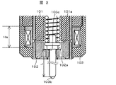
図1は、本発明に係る燃料噴射弁の断面図であり、図2は可動子の近傍の拡大図である。 FIG. 1 is a cross-sectional view of a fuel injection valve according to the present invention, and FIG. 2 is an enlarged view of the vicinity of a mover.
燃料噴射弁1は、大径部107aと、小径部107bと、大径部107aと小径部107bとの間をつなぐ縮径部107cとを有するハウジング107を有する。ハウジング107の大径部107aの内側には、磁気コア101(固定コア,可動鉄心或いは単にコアとも言う),可動子102(可動コア或いは可動鉄心とも言う),第1のロッドガイド104,付勢バネ106,ゼロ位置バネ108,バネ押さえ114が収容されている。ハウジング107の小径部107bの先端部には、弁座110と噴射孔111とが形成されたノズル112が固定され、ノズル112の内側に第2のロッドガイド113が収容されている。また、ハウジング107の大径部107aと小径部107bとにまたがって弁体103が収容されている。
The fuel injection valve 1 includes a
ハウジング107の大径部107aの外側には、コイル15と、このコイル105を取り囲むようにヨーク109とが設けられている。
A coil 15 and a
図1に示した燃料噴射弁1は、通常時閉型の電磁弁(電磁式燃料噴射弁)であり、コイル105に通電されていない状態では付勢バネ106によって弁体103のシート部103b(図2参照)がノズル112の弁座110に密着させられ、弁は閉じた状態になっている。なお、シート部103bは弁体103に構成されたロッド部103aの先端部に設けられている。この閉弁状態においては、可動子102はゼロ位置バネ108によって弁体103の衝突面103c側に密着せられ、可動子102とコア101との間には隙間がある状態となっている(図2参照)。弁体103の衝突面103cは、ロッド部103aの、シート部103bが形成された先端部とは反対側の端部に設けられている。
The fuel injection valve 1 shown in FIG. 1 is a normally closed electromagnetic valve (electromagnetic fuel injection valve). When the
第1のロッドガイド104は弁体103を内包するハウジング107の大径部107aの内側に固定されており、第1のロッドガイド104は弁体103がそのストローク方向に移動可能なように、ロッド部103aをガイドしている。また、この第1のロッドガイド104はゼロ位置バネ108のバネ座を構成している。第1のロッドガイド104は、弁体103のストローク方向において、可動子102よりもノズル112側に配置されている。
The
ハウジング107の小径部107bの先端部には第2のロッドガイド113が設けられており、ロッド部103aの先端側(シート部103b側)で弁体103をそのストローク方向に移動可能なようにガイドしている。
A
付勢バネ106はコア101の内径部に設けられており、その付勢力は、コア101の内径部に固定されるバネ押さえ114の押し込み量によって組み立て時に調整されている。
The urging
可動子102の内径部には弁体103のロッド部10aが貫通しており、可動子102は弁体103のストローク方向(ロッド部103aの軸方向)に弁体103に対して相対変位可能に組み付けられている。
The rod portion 10a of the
コイル105とコア101及び可動子102とは弁体103の駆動手段となる電磁石を構成する。第1の付勢手段となる付勢バネ106は駆動手段による駆動力の向きとは逆向き(閉弁方向)に弁体103を付勢する。また第2の付勢手段となるゼロ位置バネ108は付勢バネ106による付勢力よりも小さい付勢力で可動子102を駆動力の向き(閉弁方向)に付勢する。
The
コイル105に電流が流れると、コア101,可動子102,ヨーク109から構成される磁気回路に磁束が生じ、可動子102とコア101の間の隙間にも磁束が通過する。この結果、可動子102には磁気吸引力が作用し、生じた磁気吸引力が付勢バネ106による力を超えたときに可動子102はコア101の側に変位する。可動子102が変位する際には、可動子側の衝突面102aと弁体側の衝突面103cとの間で力を伝達し(図2参照)、弁体103も同時に変位することで、弁体は開弁状態となる。この開弁状態における弁体103のリフト量は、弁体側の衝突面103cと弁座110に接触する弁体103のシート部103bとの距離L(図2参照)によって調整されている。
When a current flows through the
開弁状態からコイル105に流れている電流を停止すると、磁気回路を流れる磁束が減少し、可動子102とコア101との間で働く磁気吸引力が低下する。ここで、弁体103にはたらく付勢バネ106による力は、弁体103から弁体側の衝突面103cおよび可動子側の衝突面102aを介して可動子102に伝達される。このため、磁気吸引力を付勢バネ106による力が上回ると可動子102および弁体103は閉弁方向に変位し、弁体103は閉弁状態となる。
When the current flowing through the
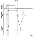
弁体103が閉弁状態となって弁体103の運動が停止した後においても、弁体103との間で相対運動が可能な可動子102は、運動を継続する。図3は、この様子を、可動子102及び弁体103の変位量で示したタイムチャートである。
Even after the
図3で示されたように、通電が完了(t3)した後に閉弁が開始され、閉弁が完了(t4)した後にも可動子102が運動を継続する。可動子102が運動を継続している間では、可動子102と磁気コア101の距離が大きく、弁体103と可動子102が当接する面が離れているため、可動子102が運動を継続している期間に再び通電を開始しても磁気吸引力が充分に大きくなるまでに時間を要してしまう。このため、近接して複数回の燃料噴射を行わせるためには、噴射終了後に一定の待ち時間が必要になることがある。また、急速に大電流を投入することで複数回噴射の間隔を短縮することも可能であるが、筒内噴射エンジンに用いられる燃料噴射弁では、大電流を投入するためには高い電圧が必要であり、この高い電圧は非噴射期間に昇圧されてコンデンサに蓄えた高圧電源によって供給される。この高い電圧は高圧電源から電荷を放出(コンデンサからの放電)することによって得られるため、近接した時間内に複数回の噴射を行う場合には、前に開弁した際の放電の後に行う蓄電が間に合わず、十分な効果を得にくい場合がある。また、エンジンの一行程中に複数回の噴射を行わせると、高圧電源からの充放電の回数が増加することになり、したがって昇圧回路の動作回数や動作時間及び消費電力が増加し、素子の発熱も大きくなってしまう。
As shown in FIG. 3, the valve closing is started after energization is completed (t 3 ), and the
このような問題に対応するように駆動回路を製作すると、電圧降下を抑制するためにコンデンサの容量を大きくしたり、あるいは大きい消費電力に耐える電子素子の選定や放熱構造を採用する必要が生じて、結果としてコストの上昇を招いたり、あるいは実装が困難になってしまうことがあった。 When a drive circuit is manufactured to deal with such problems, it is necessary to increase the capacity of the capacitor in order to suppress the voltage drop, or to select an electronic element that can withstand large power consumption and to adopt a heat dissipation structure. As a result, the cost may increase or the mounting may become difficult.
そこで、本実施例では、高圧電源からの電圧印加シーケンスを一回目の噴射と二回目以降の噴射で異ならせ、一回目の噴射は二回目の噴射よりも高圧電源の消費電力が小さくなるように設定する。 Therefore, in this embodiment, the voltage application sequence from the high-voltage power supply is different between the first injection and the second and subsequent injections so that the first injection consumes less power than the second injection. Set.
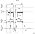
図4は、本発明にかかる燃料噴射弁の駆動シーケンスを示す図である。図4に示した駆動シーケンスでは、高圧電源からの供給時間を、一回目の噴射時には、二回目の噴射時よりも短く設定することで、一回目の噴射時の高圧電源の消費電力が二回目よりも小さくなるように設定されている。図4においては、最初の高電圧印加402(t12〜t13)の方が、二回目の高電圧印加408(t15〜t16)よりも短い印加時間になるように設定されており、この結果高電圧印加に投入される電力が少なく済むようになっている。 FIG. 4 is a diagram showing a drive sequence of the fuel injection valve according to the present invention. In the driving sequence shown in FIG. 4, the power supply time of the high-voltage power supply at the first injection is set to be shorter at the first injection by setting the supply time from the high-voltage power supply shorter than at the second injection. It is set to be smaller. In FIG. 4, the first high voltage application 402 (t 12 to t 13 ) is set to have a shorter application time than the second high voltage application 408 (t 15 to t 16 ). As a result, less electric power is applied to the high voltage application.
一回目の噴射時には、図4の電圧印加401のように、始めに昇圧されていないバッテリ電圧からの電圧印加を所定の期間(t10〜t12)行い、所定の電流値に制御しながら行う。この電圧印加401によって生じる電流403では、燃料噴射弁の可動子102は変位を開始せず、したがって開弁しない。このように、予め燃料噴射弁1の磁気回路中に開弁にはやや不足する程度の磁気吸引力を発生させておくことで、高圧電源からの電流404およびその電力供給が少ない場合においても燃料噴射弁1の開弁が可能になる。また、予め電流403によって燃料噴射弁1の磁気回路中に磁束を生じさせておくと、コイル105のインダクタンスが低下して電流404の立ち上がりが二回目の噴射時の高電圧印加による電流409よりも素早くなる。この結果、高電圧印加402の時間が短い場合においても、電流404を急速に立ち上げて開弁に必要な電流を供給することができるようになる。
At the time of the first injection, voltage application from the battery voltage that is not first boosted is performed for a predetermined period (t 10 to t 12 ) and controlled to a predetermined current value as in the
また、一般に高電圧印加終了後にはダイオード等によって逆電圧を発生させ、電流の立ち下りを高速に行わせることが、印加電圧411および412のように行われる。ここで、一回目の噴射時には高電圧印加402の終了後の逆電圧411印加までの間に、電圧を印加せずに電流をコイルの両端間で還流させる期間410を設けると良い。急速に電流を立ち下げずに電流を還流させることによって、高電圧印加による電流404を有効に活用し、電流値の降下を緩やかにすることによって、電流よりも遅れて立ち上がる磁気吸引力の上昇を補助することができる。このようにすることによって、高電圧印加402の期間が短い場合であっても、開弁をより安定して行わせることができる。
In general, after the application of the high voltage, a reverse voltage is generated by a diode or the like to cause the current to fall at high speed as in the case of the applied
一方で、二回目の噴射パルス407による電圧印加時には、高電圧印加408の期間を最初の噴射時の高電圧印加402よりも長くとる。このようにすることで、駆動電流409を可能な限り高速に投入できるようになり、可動子が一回目の噴射終了後に運動を継続していても、可動子を磁気吸引力によって引き戻して再噴射させることができる。
On the other hand, at the time of voltage application by the
このように設定した場合、パルス406による通電開始から噴射開始までの開弁遅れ時間が一回目の噴射時には長くなってしまうが、この問題は予め噴射パルスを開弁遅れ時間が長くなってしまう分だけ早いタイミングで与えることで解消できる。一方で、一回目の噴射後に二回目の噴射を行う時点では、高圧電源からの電力を一回目よりも多く使うことができ、したがって一回目と二回目の噴射間隔を短くしても安定した噴射動作が可能になる。
When set in this way, the valve opening delay time from the start of energization by the
一回目と二回目の噴射間隔を短くできることで、エンジンの一行程中で噴射を行えない時間を少なくすることができる。このような分割噴射をエンジンの高負荷領域で行う場合においても、噴射可能期間が短くなるより高回転まで分割噴射を行わせることができるようになる。 By shortening the first and second injection intervals, it is possible to reduce the time during which the engine cannot be injected during one stroke of the engine. Even when such split injection is performed in a high load region of the engine, it becomes possible to perform split injection until a higher rotation than the possible injection period becomes shorter.
このように、一回目の噴射時に昇圧電圧を印加する期間を二回目よりも短くすることで、エンジンの一行程中に複数回の噴射を行ったとしても、昇圧電源の消費電力が著しく大きくなってしまうのを抑制することができる。この結果、大きいコンデンサや冷却構造及び高価な電子素子などを使用しなくても分割噴射を行わせることができたり、あるいは分割噴射が可能なエンジンの運転範囲を拡大することができる。 In this way, by shortening the period during which the boost voltage is applied at the time of the first injection, the power consumption of the boost power supply is significantly increased even if multiple injections are performed during one stroke of the engine. Can be suppressed. As a result, the divided injection can be performed without using a large condenser, a cooling structure, an expensive electronic element, or the like, or the operating range of the engine capable of the divided injection can be expanded.
上述のように一回目と二回目の高電圧の印加シーケンスを変える方法としては、ECU(エンジンコントロールユニット)と燃料噴射弁1の駆動IC(駆動のための集積回路)との間の通信を、一回目の噴射パルスの開始後に行って、二回目の噴射までの間に設定値を変えることで行っても良い。 As described above, as a method of changing the first and second high voltage application sequences, communication between the ECU (engine control unit) and the driving IC (integrated circuit for driving) of the fuel injection valve 1 is performed. It may be performed after the start of the first injection pulse and by changing the set value before the second injection.
図5に例を示すように、燃料噴射弁1の駆動IC503は燃料噴射弁1への電圧印加シーケンスを制御する集積回路で、ECUから入力された噴射パルスに対して、予めECUとの通信によって設定された駆動シーケンスに基づいた電圧印加および駆動電流制御を行うように、燃料噴射弁1に接続されたFETやトランジスタなどのスイッチング素子504,505や、昇圧回路502を制御するものである。駆動シーケンスとして設定できる値としては、高電圧を印加する前のバッテリ電圧印加時間や、その電流値、高電圧印加時の最大電流値およびその保持時間、開弁状態を保持するための保持電流値が設定できるようになっていると良い。
As shown in FIG. 5, the
このようなICを用いる場合には、噴射パルスを入力すると予め設定した駆動シーケンスを行ってしまうので、一回目と二回目の噴射を区別することができない。そこで、前述のように一回目の噴射パルス開始後に設定値を変える通信をECUが行い、二回目の噴射より前に設定が変更されるようにECUがプログラムされていると良い。特に噴射間隔が短いことが望ましいエンジンの高負荷条件下では、噴射期間を比較的長く取ることが可能なので、上記のような通信を行うことが比較的簡単にできる。 When such an IC is used, since a preset drive sequence is performed when an injection pulse is input, it is not possible to distinguish between the first and second injections. Therefore, as described above, the ECU may be programmed so that the ECU performs communication for changing the set value after the start of the first injection pulse, and the setting is changed before the second injection. In particular, under the high load condition of the engine where it is desirable that the injection interval is short, it is possible to make the injection period relatively long, so that the communication as described above can be performed relatively easily.
図5の駆動回路について、さらに詳細に説明する。燃料噴射弁1のコイルの一方の端子にはスイッチング素子504を介してコンデンサ501が接続され、コンデンサ501には昇圧回路502が接続されている。燃料噴射弁1のコイルの他方の端子はスイッチング素子505,抵抗506を介して接地されている。スイッチング素子504,505のベースには駆動IC503からの信号線511が接続され、駆動IC503からの信号によってスイッチング素子504,505が個別にON,OFFされるように構成されている。駆動IC503と制御ユニットであるECU(エンジンコントロールユニット)510との間には通信線512が設けられ、さらにECU510からは信号線513によって噴射パルスが駆動IC503に指令されるように構成されている。燃料噴射弁1とスイッチング素子504との間には、ダイオード514を介してバッテリ電圧515が接続されている。ダイオード514とバッテリ電圧516との間の配線部と燃料噴射弁1とスイッチング素子505との間の配線部はスイッチング素子507を介して接続されている。なお、ダイオード514とバッテリ電圧515との間の配線部とスイッチング素子507との間にはダイオード515が設けられている。また、スイッチング素子507と燃料噴射弁1との間の配線部と、スイッチング素子505と抵抗506との間の配線部とが、ツェナーダイオード508を介して接続されている。スイッチング素子507のベースには駆動IC503からの信号線511の一本が接続され、駆動IC503からの信号によってスイッチング素子507が他のスイッチング素子504,505とは個別にON,OFFされるように構成されている。
The drive circuit of FIG. 5 will be described in further detail. A
コンデンサ501には昇圧回路502から電荷が蓄えられる。図4のt10からt12までの期間は燃料噴射弁1にバッテリ電圧516が印加される。この場合、スイッチング素子504はOFFされ、スイッチング素子505がONされる。特に、t11からt12の期間では、スイッチング素子505のON,OFFを繰り返すことによって、駆動電流403が第1の設定値に維持される。t12からt13の期間では、スイッチング素子504とスイッチング素子505の両方がONされる。t13でスイッチング素子504はOFFされ、t14までの期間は駆動電流が第2の設定値に維持されるよう(405)、スイッチング素子505のON,OFFを繰り返す。t14からt15の期間は、スイッチング素子504,505は共にOFFされる。
Charge is stored in the
噴射制御パルス407に対応して、t15からt16の期間は、スイッチング素子504,505は共にONされ、燃料噴射弁1のコイルには電圧408が印加される。t16からt17の期間は、スイッチング素子504はOFFされ、駆動電流が第2の設定値に維持されるよう(413)、スイッチング素子505のON,OFFを繰り返す。
Corresponding to the
図5に示すように、燃料噴射弁1の駆動はスイッチング素子504及び505を用いることによって行わせることができるが、燃料噴射弁1の駆動電流値を一定に保つ場合のように駆動電流を急峻に変化させたくない場合と、噴射制御パルスの停止する場合のように駆動電流を急峻に変化させたい場合とがある。これを制御するために、スイッチング素子507を用いる。
As shown in FIG. 5, the fuel injection valve 1 can be driven by using the switching
通常、スイッチング素子505により、燃料噴射弁1への駆動電流を遮断した時には、スイッチング素子505の上流509の電位は著しく上昇する。このようなフライバック電圧への対処法としては、燃料噴射弁1へ還流させることでフライバック電圧を抑える方法と、ツェナーダイオードなどによって逆電圧をかけながら接地させる方法がある。
Usually, when the drive current to the fuel injection valve 1 is cut off by the switching
図5において、スイッチング素子507をONにした状態では、フライバック電圧は燃料噴射弁1へ還流されるため、燃料噴射弁1の両端の電位差は逆電圧とはならず、電流変化は緩やかになる。一方で、スイッチング素子507をOFFにした状態では大きなフライバック電圧が生じ、点509の電位が上昇する。ここで、フライバック電圧によってスイッチング素子505が破損しないようにするため、ツェナーダイオード508を用いると良い。スイッチング素子507がOFFの状態でスイッチング素子505がOFFになると、ツェナーダイオード508のツェナー電圧が点509の電位となり、燃料噴射弁1には逆電圧がかかった状態となり、電流を素早く変化させることができる。
In FIG. 5, when the switching
本実施例に係る燃料噴射弁及びその駆動方法を用いることによって、エンジンの一行程中に複数回の燃料噴射を行わせることが容易となり、高負荷でのすすの低減や、始動や暖機時の弱成層運転による未燃炭化水素成分の排出抑制などを図ることができる。 By using the fuel injection valve and its driving method according to the present embodiment, it becomes easy to perform a plurality of fuel injections during one stroke of the engine, soot reduction at a high load, start-up and warm-up It is possible to suppress the emission of unburned hydrocarbon components by the weak stratification operation.
なお、一行程中に3回以上の噴射を行わせる場合には、二回目以降のいずれかの噴射時の昇圧電源からの消費電力より、一回目の噴射時の昇圧電源からの消費電力が小さくなるように設定すると良い。特に、噴射の時間間隔が短くなるタイミングで、大きい電力を投入するようにすることで、最小の噴射時間間隔を短く設定できるようになる。 In addition, in the case where three or more injections are performed during one stroke, the power consumption from the boost power source at the first injection is smaller than the power consumption from the boost power source at any one of the second and subsequent injections. It is good to set so that In particular, the minimum injection time interval can be set short by supplying large electric power at the timing when the injection time interval becomes short.
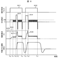
図6は、本発明に係る燃料噴射弁の駆動方法の実施形態の例であって、一回目の噴射と二回目以降いずれかの噴射の電圧印加シーケンスを変化させる方法として、昇圧電源によって投入される電流値のピーク値が、一回目の噴射時には二回目以降いずれかの噴射時より小さくなるように設定する。 FIG. 6 is an example of an embodiment of a method for driving a fuel injection valve according to the present invention. As a method for changing the voltage application sequence between the first injection and the second and subsequent injections, The peak value of the current value is set to be smaller at the time of the first injection than at the time of any of the second and subsequent injections.
図6において、一回目の噴射時の昇圧電源による印加電圧603の噴射期間(t12〜t13′)は、一回目のピーク電流の目標値605に昇圧電源からの投入電流607達するまでの期間で定まるように設定されている。
In FIG. 6, the injection period (t 12 to t 13 ′) of the applied
回路上は、図5におけるシャント抵抗506の電位を駆動IC503に入力し、設定値との比較を駆動IC503が行うことによって昇圧電源電圧の印加時間を決定する。
On the circuit, the potential of the
二回目の噴射時には、ピーク電流の目標値を目標値606のように一回目の噴射時よりも大きく設定することで、一回目の噴射時には二回目の噴射時よりも少ない消費電力で開弁できるように設定する。
At the time of the second injection, the peak current target value is set larger than that at the time of the first injection as the
このように、ピーク電流の目標値605及び606を用いることによって、一回目と二回目以降の電圧印加シーケンスを異ならせることができる。 Thus, by using the peak current target values 605 and 606, the first and second and subsequent voltage application sequences can be made different.
スイッチング素子504,505,507のON,OFFは実施例1と同様に行われる。
The switching
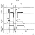
図7は、本発明に係る燃料噴射弁の駆動方法の実施形態の例であって、一回目の噴射時に印加する昇圧電源からの電圧印加703を、スイッチングすることによって、二回目以降の電圧印加704よりも消費電力を低減させた例である。
FIG. 7 is an example of an embodiment of a method for driving a fuel injection valve according to the present invention, in which
このように、昇圧電源から供給した電圧をスイッチングして印加することによって、一回目のピーク電流705を一定値に保ちながら弁体を開弁させることができる。 In this way, by switching and applying the voltage supplied from the boost power supply, the valve element can be opened while maintaining the first peak current 705 at a constant value.
スイッチングすることにより、昇圧電源によって投入される電流が過剰になるのを防ぎながら、なおかつ磁気吸引力が十分に立ち上がるのを待って開弁sなせることができるため、一回目の噴射をより安定して行わせられる。 By switching, it is possible to open the valve while waiting for the magnetic attractive force to rise sufficiently while preventing the current supplied by the boost power supply from becoming excessive, so the first injection is more stable To be done.
特に、過剰な電流値に到達するのを防げるため、一回目の噴射量が微小であっても、これを正確に計量して噴射することを行わせやすくなる。 In particular, in order to prevent an excessive current value from being reached, even if the first injection amount is very small, it becomes easy to accurately measure and inject the injection amount.
図7のt10からt21までの期間は燃料噴射弁1にバッテリ電圧515が印加される。この場合、スイッチング素子504はOFFされ、スイッチング素子505がONされる。t21からt22の期間では、スイッチング素子504がONされ、スイッチング素子505のON,OFFを繰り返す。t22からt24の期間はスイッチング素子504はOFFされ、駆動電流が設定値に維持されるよう、スイッチング素子505のON,OFFを繰り返す。移行は、実施例1または実施例2と同様である。
The
101 磁気コア
102 可動子(アンカ)
102a 可動子側の衝突面
103 弁体
103c 弁体側の衝突面
104 第1のロッドガイド
105 コイル
106 付勢バネ
107 ハウジング
108 ゼロ位置バネ
109 ヨーク
110 弁座
111 噴射孔
112 ノズル
113 第2のロッドガイド
401 バッテリ電圧の印加
402 一回目の昇圧電圧印加
403 電流
404,409 昇圧電源による電流
405 保持電流
406,407,601,602,701,702 駆動パルス
408 二回目の昇圧電圧印加
410 電流の還流期間
411,412 急峻立ち下げの逆電圧印加
501 コンデンサ
502 昇圧回路
503 駆動IC
504,505 スイッチング素子
506 シャント抵抗
603,604,703,704 昇圧電源からの電圧印加
605,606 ピーク電流目標値
607,608,705,706 昇圧電源からの駆動電流
101
102a Colliding
504, 505
Claims (6)
前記電磁式燃料噴射弁が内燃機関の一行程中に少なくとも二回の燃料噴射を行うように駆動電流を与え、第一回目の噴射時に印加する第1の昇圧電圧による消費電力が、二回目以降のいずれかの噴射時に印加する第2の昇圧電圧による消費電力よりも小さくなるように、第1の昇圧電圧と第2の昇圧電圧の印加シーケンスが異なって設定されたことを特徴とする電磁式燃料噴射弁の駆動回路。 A valve body that closes the fuel passage by abutting against the valve seat and opens the fuel passage by moving away from the valve seat; a movable element that transmits force between the valve body and performs an on-off valve operation; and the movable element An electromagnetic fuel injection valve drive circuit comprising an electromagnet having a coil and a magnetic core provided as drive means, and biasing means for biasing the valve body in a direction opposite to the direction of the drive force by the drive means. In the drive circuit of the electromagnetic fuel injection valve having the ability to apply a voltage boosted to a voltage higher than the battery voltage to the coil,
Said driving current example given as an electromagnetic type fuel injection valve is performed at least two fuel injections in one stroke of the internal combustion engine, the power consumption by the first boosted voltage to be applied during the first round of injection, the second time An electromagnetic wave characterized in that the application sequence of the first boosted voltage and the second boosted voltage is set differently so as to be smaller than the power consumption by the second boosted voltage applied during any of the subsequent injections Type fuel injection valve drive circuit.
Priority Applications (5)
| Application Number | Priority Date | Filing Date | Title |
|---|---|---|---|
| JP2009270971A JP5331663B2 (en) | 2009-11-30 | 2009-11-30 | Electromagnetic fuel injection valve drive circuit |
| US13/512,406 US8899210B2 (en) | 2009-11-30 | 2010-08-16 | Drive circuit for electromagnetic fuel-injection valve |
| PCT/JP2010/063805 WO2011065072A1 (en) | 2009-11-30 | 2010-08-16 | Drive circuit for electromagnetic fuel-injection valve |
| CN201080053746.9A CN102639860B (en) | 2009-11-30 | 2010-08-16 | Drive circuit of electromagnetic fuel injection valve |
| EP10832919.4A EP2508743B1 (en) | 2009-11-30 | 2010-08-16 | Drive circuit for electromagnetic fuel-injection valve |
Applications Claiming Priority (1)
| Application Number | Priority Date | Filing Date | Title |
|---|---|---|---|
| JP2009270971A JP5331663B2 (en) | 2009-11-30 | 2009-11-30 | Electromagnetic fuel injection valve drive circuit |
Publications (3)
| Publication Number | Publication Date |
|---|---|
| JP2011112008A JP2011112008A (en) | 2011-06-09 |
| JP2011112008A5 JP2011112008A5 (en) | 2012-06-07 |
| JP5331663B2 true JP5331663B2 (en) | 2013-10-30 |
Family
ID=44066174
Family Applications (1)
| Application Number | Title | Priority Date | Filing Date |
|---|---|---|---|
| JP2009270971A Expired - Fee Related JP5331663B2 (en) | 2009-11-30 | 2009-11-30 | Electromagnetic fuel injection valve drive circuit |
Country Status (5)
| Country | Link |
|---|---|
| US (1) | US8899210B2 (en) |
| EP (1) | EP2508743B1 (en) |
| JP (1) | JP5331663B2 (en) |
| CN (1) | CN102639860B (en) |
| WO (1) | WO2011065072A1 (en) |
Families Citing this family (24)
| Publication number | Priority date | Publication date | Assignee | Title |
|---|---|---|---|---|
| DE102011005672B4 (en) * | 2011-03-17 | 2019-07-11 | Continental Automotive Gmbh | Method, device and computer program for the electrical control of an actuator for determining the time of an anchor stop |
| JP5358621B2 (en) | 2011-06-20 | 2013-12-04 | 日立オートモティブシステムズ株式会社 | Fuel injection device |
| WO2013191267A1 (en) * | 2012-06-21 | 2013-12-27 | 日立オートモティブシステムズ株式会社 | Control device for internal combustion engine |
| DE102012211994B4 (en) * | 2012-07-10 | 2024-08-08 | Vitesco Technologies GmbH | Control unit for controlling at least one fuel injection valve and circuit arrangement with such a control unit |
| DE102012213883B4 (en) * | 2012-08-06 | 2015-03-26 | Continental Automotive Gmbh | Equalization of the current flow through a fuel injector for different partial injection processes of a multiple injection |
| JP5849975B2 (en) * | 2013-02-25 | 2016-02-03 | 株式会社デンソー | Fuel injection control device and fuel injection system |
| JP5815590B2 (en) * | 2013-04-05 | 2015-11-17 | 本田技研工業株式会社 | Solenoid valve drive |
| JP6130280B2 (en) * | 2013-09-25 | 2017-05-17 | 日立オートモティブシステムズ株式会社 | Drive device for fuel injection device |
| JP2015102052A (en) * | 2013-11-26 | 2015-06-04 | 株式会社デンソー | Fuel injection control device |
| EP2918816B1 (en) * | 2014-03-14 | 2017-09-06 | Continental Automotive GmbH | Fuel injector |
| GB2524259A (en) * | 2014-03-17 | 2015-09-23 | Gm Global Tech Operations Inc | Method of operating a fuel injector |
| GB2534172A (en) * | 2015-01-15 | 2016-07-20 | Gm Global Tech Operations Llc | Method of energizing a solenoidal fuel injector for an internal combustion engine |
| DE102015219383B3 (en) | 2015-10-07 | 2017-02-09 | Continental Automotive Gmbh | Determining a time when a fuel injector is in a predetermined state |
| JP6557608B2 (en) * | 2016-01-22 | 2019-08-07 | 日立オートモティブシステムズ株式会社 | Control device for fuel injection device |
| US10060399B2 (en) * | 2016-04-22 | 2018-08-28 | GM Global Technology Operations LLC | Method and apparatus for optimum drive signal control of an electromagnetically-activated actuator |
| WO2018037734A1 (en) * | 2016-08-26 | 2018-03-01 | 日立オートモティブシステムズ株式会社 | Control device for fuel injection device |
| JP6720935B2 (en) * | 2017-07-28 | 2020-07-08 | 株式会社Soken | Fuel injection control device and fuel injection control method |
| JP6939472B2 (en) | 2017-11-27 | 2021-09-22 | トヨタ自動車株式会社 | Internal combustion engine control device |
| US11098669B2 (en) * | 2018-03-22 | 2021-08-24 | Hitachi Automotive Systems, Ltd. | Internal combustion engine control device |
| CN108656741B (en) * | 2018-05-21 | 2020-06-02 | 苏州华兴源创科技股份有限公司 | Ink-jet dotting device and method controlled by electromagnetic valve |
| JP6642653B2 (en) * | 2018-08-24 | 2020-02-12 | 株式会社デンソー | Fuel injection control device and fuel injection system |
| JP7256772B2 (en) * | 2020-03-30 | 2023-04-12 | 日立Astemo株式会社 | CONTROL DEVICE, CONTROL METHOD AND PROGRAM FOR FUEL INJECTION DEVICE |
| KR102514687B1 (en) * | 2021-05-11 | 2023-03-27 | 주식회사 현대케피코 | Apparatus for controlling boost voltage of gdi engine injector and method thereof |
| CN115628145B (en) * | 2022-10-24 | 2023-04-14 | 南京工业大学 | Current type driving circuit and driving control method of gas-assisted atomizing nozzle |
Family Cites Families (14)
| Publication number | Priority date | Publication date | Assignee | Title |
|---|---|---|---|---|
| US4774624A (en) * | 1987-07-06 | 1988-09-27 | Motorola, Inc. | Boost voltage power supply for vehicle control system |
| JP3021182B2 (en) * | 1992-04-20 | 2000-03-15 | 三菱重工業株式会社 | Electromagnetic unit injector |
| DE4411789C2 (en) * | 1994-04-06 | 2003-12-11 | Bosch Gmbh Robert | Method and device for controlling the fuel metering in an internal combustion engine |
| JPH1162677A (en) * | 1997-08-08 | 1999-03-05 | Denso Corp | Solenoid valve driving device |
| DE19813138A1 (en) * | 1998-03-25 | 1999-09-30 | Bosch Gmbh Robert | Method and device for controlling an electromagnetic consumer |
| JP2000130230A (en) * | 1998-10-23 | 2000-05-09 | Isuzu Motors Ltd | Engine fuel injection control device |
| JP3671785B2 (en) * | 1999-12-15 | 2005-07-13 | 株式会社日立製作所 | Fuel injection device for in-cylinder injection type internal combustion engine |
| JP5055050B2 (en) * | 2006-10-10 | 2012-10-24 | 日立オートモティブシステムズ株式会社 | Internal combustion engine control device |
| DE102006060311A1 (en) | 2006-12-20 | 2008-06-26 | Robert Bosch Gmbh | Method for operating an injection valve |
| JP4691523B2 (en) * | 2007-05-09 | 2011-06-01 | 日立オートモティブシステムズ株式会社 | Control circuit for electromagnetic fuel injection valve |
| JP4925976B2 (en) * | 2007-08-29 | 2012-05-09 | 株式会社ケーヒン | Internal combustion engine control device |
| US7878177B2 (en) * | 2007-10-23 | 2011-02-01 | Ford Global Technologies, Llc | Internal combustion engine having common power source for ion current sensing and fuel injectors |
| EP2060762A1 (en) | 2007-11-15 | 2009-05-20 | Delphi Technologies, Inc. | Glitch detector and method of detecting glitch events |
| JP4776651B2 (en) * | 2008-03-28 | 2011-09-21 | 日立オートモティブシステムズ株式会社 | Internal combustion engine control device |
-
2009
- 2009-11-30 JP JP2009270971A patent/JP5331663B2/en not_active Expired - Fee Related
-
2010
- 2010-08-16 US US13/512,406 patent/US8899210B2/en not_active Expired - Fee Related
- 2010-08-16 CN CN201080053746.9A patent/CN102639860B/en not_active Expired - Fee Related
- 2010-08-16 WO PCT/JP2010/063805 patent/WO2011065072A1/en not_active Ceased
- 2010-08-16 EP EP10832919.4A patent/EP2508743B1/en not_active Not-in-force
Also Published As
| Publication number | Publication date |
|---|---|
| WO2011065072A1 (en) | 2011-06-03 |
| EP2508743A4 (en) | 2015-10-21 |
| CN102639860A (en) | 2012-08-15 |
| US8899210B2 (en) | 2014-12-02 |
| EP2508743B1 (en) | 2017-08-16 |
| CN102639860B (en) | 2015-04-15 |
| US20120234299A1 (en) | 2012-09-20 |
| EP2508743A1 (en) | 2012-10-10 |
| JP2011112008A (en) | 2011-06-09 |
Similar Documents
| Publication | Publication Date | Title |
|---|---|---|
| JP5331663B2 (en) | Electromagnetic fuel injection valve drive circuit | |
| JP4691523B2 (en) | Control circuit for electromagnetic fuel injection valve | |
| JP5492806B2 (en) | Drive device for electromagnetic fuel injection valve | |
| CN103069138B (en) | Drives for fuel injection devices | |
| US6332453B1 (en) | Electromagnetic system fuel injection apparatus an internal combustion engine having an electromagnetic system fuel injection apparatus, and a drive circuit of an electromagnetic system fuel injection apparatus | |
| JPH11280527A (en) | Method and device for controlling current rise time in multiple fuel injection event | |
| JP5772788B2 (en) | Fuel injection control device and fuel injection system | |
| US8020533B2 (en) | Fuel injection device, fuel injection control device, and control method of fuel injection device | |
| JP6414022B2 (en) | Fuel injection control device and fuel injection system | |
| JP6561184B2 (en) | Drive device for fuel injection device | |
| JP7177458B2 (en) | A controller that controls the fuel injection system | |
| JP2018031294A (en) | Solenoid valve drive | |
| JP3772397B2 (en) | Fuel injection valve drive circuit | |
| JP2014129817A (en) | Drive device of electromagnetic fuel injection valve | |
| JP4695544B2 (en) | Control method of fuel injection device | |
| JP2001165014A (en) | Fuel injection device | |
| JP6957224B2 (en) | Solenoid valve drive device | |
| JP4695543B2 (en) | Fuel injection device and fuel injection control device | |
| JP7047139B2 (en) | Control device and program to control the fuel injection valve | |
| JP3094020B2 (en) | Switching device for exciting electromagnetic biasing member and method of operating the device | |
| JP2014156867A (en) | Drive unit of solenoid valve device | |
| JP2004132381A (en) | Fuel injection device |
Legal Events
| Date | Code | Title | Description |
|---|---|---|---|
| A521 | Written amendment |
Free format text: JAPANESE INTERMEDIATE CODE: A523 Effective date: 20120411 |
|
| A621 | Written request for application examination |
Free format text: JAPANESE INTERMEDIATE CODE: A621 Effective date: 20120411 |
|
| A521 | Written amendment |
Free format text: JAPANESE INTERMEDIATE CODE: A523 Effective date: 20120411 |
|
| TRDD | Decision of grant or rejection written | ||
| A01 | Written decision to grant a patent or to grant a registration (utility model) |
Free format text: JAPANESE INTERMEDIATE CODE: A01 Effective date: 20130702 |
|
| A61 | First payment of annual fees (during grant procedure) |
Free format text: JAPANESE INTERMEDIATE CODE: A61 Effective date: 20130729 |
|
| R150 | Certificate of patent or registration of utility model |
Free format text: JAPANESE INTERMEDIATE CODE: R150 |
|
| LAPS | Cancellation because of no payment of annual fees |

