JP5330552B2 - Video display device and television receiver - Google Patents
Video display device and television receiver Download PDFInfo
- Publication number
- JP5330552B2 JP5330552B2 JP2012017806A JP2012017806A JP5330552B2 JP 5330552 B2 JP5330552 B2 JP 5330552B2 JP 2012017806 A JP2012017806 A JP 2012017806A JP 2012017806 A JP2012017806 A JP 2012017806A JP 5330552 B2 JP5330552 B2 JP 5330552B2
- Authority
- JP
- Japan
- Prior art keywords
- unit
- video signal
- luminance
- input
- video
- Prior art date
- Legal status (The legal status is an assumption and is not a legal conclusion. Google has not performed a legal analysis and makes no representation as to the accuracy of the status listed.)
- Active
Links
Images


Classifications
-
- H—ELECTRICITY
- H04—ELECTRIC COMMUNICATION TECHNIQUE
- H04N—PICTORIAL COMMUNICATION, e.g. TELEVISION
- H04N5/00—Details of television systems
- H04N5/66—Transforming electric information into light information
-
- G—PHYSICS
- G09—EDUCATION; CRYPTOGRAPHY; DISPLAY; ADVERTISING; SEALS
- G09G—ARRANGEMENTS OR CIRCUITS FOR CONTROL OF INDICATING DEVICES USING STATIC MEANS TO PRESENT VARIABLE INFORMATION
- G09G3/00—Control arrangements or circuits, of interest only in connection with visual indicators other than cathode-ray tubes
- G09G3/20—Control arrangements or circuits, of interest only in connection with visual indicators other than cathode-ray tubes for presentation of an assembly of a number of characters, e.g. a page, by composing the assembly by combination of individual elements arranged in a matrix no fixed position being assigned to or needed to be assigned to the individual characters or partial characters
- G09G3/34—Control arrangements or circuits, of interest only in connection with visual indicators other than cathode-ray tubes for presentation of an assembly of a number of characters, e.g. a page, by composing the assembly by combination of individual elements arranged in a matrix no fixed position being assigned to or needed to be assigned to the individual characters or partial characters by control of light from an independent source
- G09G3/3406—Control of illumination source
- G09G3/342—Control of illumination source using several illumination sources separately controlled corresponding to different display panel areas, e.g. along one dimension such as lines
- G09G3/3426—Control of illumination source using several illumination sources separately controlled corresponding to different display panel areas, e.g. along one dimension such as lines the different display panel areas being distributed in two dimensions, e.g. matrix
-
- G—PHYSICS
- G09—EDUCATION; CRYPTOGRAPHY; DISPLAY; ADVERTISING; SEALS
- G09G—ARRANGEMENTS OR CIRCUITS FOR CONTROL OF INDICATING DEVICES USING STATIC MEANS TO PRESENT VARIABLE INFORMATION
- G09G3/00—Control arrangements or circuits, of interest only in connection with visual indicators other than cathode-ray tubes
- G09G3/20—Control arrangements or circuits, of interest only in connection with visual indicators other than cathode-ray tubes for presentation of an assembly of a number of characters, e.g. a page, by composing the assembly by combination of individual elements arranged in a matrix no fixed position being assigned to or needed to be assigned to the individual characters or partial characters
- G09G3/34—Control arrangements or circuits, of interest only in connection with visual indicators other than cathode-ray tubes for presentation of an assembly of a number of characters, e.g. a page, by composing the assembly by combination of individual elements arranged in a matrix no fixed position being assigned to or needed to be assigned to the individual characters or partial characters by control of light from an independent source
- G09G3/36—Control arrangements or circuits, of interest only in connection with visual indicators other than cathode-ray tubes for presentation of an assembly of a number of characters, e.g. a page, by composing the assembly by combination of individual elements arranged in a matrix no fixed position being assigned to or needed to be assigned to the individual characters or partial characters by control of light from an independent source using liquid crystals
- G09G3/3611—Control of matrices with row and column drivers
-
- H—ELECTRICITY
- H04—ELECTRIC COMMUNICATION TECHNIQUE
- H04N—PICTORIAL COMMUNICATION, e.g. TELEVISION
- H04N5/00—Details of television systems
- H04N5/44—Receiver circuitry for the reception of television signals according to analogue transmission standards
- H04N5/57—Control of contrast or brightness
-
- G—PHYSICS
- G09—EDUCATION; CRYPTOGRAPHY; DISPLAY; ADVERTISING; SEALS
- G09G—ARRANGEMENTS OR CIRCUITS FOR CONTROL OF INDICATING DEVICES USING STATIC MEANS TO PRESENT VARIABLE INFORMATION
- G09G2310/00—Command of the display device
- G09G2310/02—Addressing, scanning or driving the display screen or processing steps related thereto
- G09G2310/0237—Switching ON and OFF the backlight within one frame
-
- G—PHYSICS
- G09—EDUCATION; CRYPTOGRAPHY; DISPLAY; ADVERTISING; SEALS
- G09G—ARRANGEMENTS OR CIRCUITS FOR CONTROL OF INDICATING DEVICES USING STATIC MEANS TO PRESENT VARIABLE INFORMATION
- G09G2320/00—Control of display operating conditions
- G09G2320/02—Improving the quality of display appearance
- G09G2320/0271—Adjustment of the gradation levels within the range of the gradation scale, e.g. by redistribution or clipping
-
- G—PHYSICS
- G09—EDUCATION; CRYPTOGRAPHY; DISPLAY; ADVERTISING; SEALS
- G09G—ARRANGEMENTS OR CIRCUITS FOR CONTROL OF INDICATING DEVICES USING STATIC MEANS TO PRESENT VARIABLE INFORMATION
- G09G2320/00—Control of display operating conditions
- G09G2320/06—Adjustment of display parameters
- G09G2320/0613—The adjustment depending on the type of the information to be displayed
-
- G—PHYSICS
- G09—EDUCATION; CRYPTOGRAPHY; DISPLAY; ADVERTISING; SEALS
- G09G—ARRANGEMENTS OR CIRCUITS FOR CONTROL OF INDICATING DEVICES USING STATIC MEANS TO PRESENT VARIABLE INFORMATION
- G09G2320/00—Control of display operating conditions
- G09G2320/06—Adjustment of display parameters
- G09G2320/0626—Adjustment of display parameters for control of overall brightness
- G09G2320/064—Adjustment of display parameters for control of overall brightness by time modulation of the brightness of the illumination source
-
- G—PHYSICS
- G09—EDUCATION; CRYPTOGRAPHY; DISPLAY; ADVERTISING; SEALS
- G09G—ARRANGEMENTS OR CIRCUITS FOR CONTROL OF INDICATING DEVICES USING STATIC MEANS TO PRESENT VARIABLE INFORMATION
- G09G2320/00—Control of display operating conditions
- G09G2320/06—Adjustment of display parameters
- G09G2320/0626—Adjustment of display parameters for control of overall brightness
- G09G2320/0646—Modulation of illumination source brightness and image signal correlated to each other
-
- G—PHYSICS
- G09—EDUCATION; CRYPTOGRAPHY; DISPLAY; ADVERTISING; SEALS
- G09G—ARRANGEMENTS OR CIRCUITS FOR CONTROL OF INDICATING DEVICES USING STATIC MEANS TO PRESENT VARIABLE INFORMATION
- G09G2360/00—Aspects of the architecture of display systems
- G09G2360/16—Calculation or use of calculated indices related to luminance levels in display data
-
- G—PHYSICS
- G09—EDUCATION; CRYPTOGRAPHY; DISPLAY; ADVERTISING; SEALS
- G09G—ARRANGEMENTS OR CIRCUITS FOR CONTROL OF INDICATING DEVICES USING STATIC MEANS TO PRESENT VARIABLE INFORMATION
- G09G2370/00—Aspects of data communication
- G09G2370/20—Details of the management of multiple sources of image data
-
- H—ELECTRICITY
- H04—ELECTRIC COMMUNICATION TECHNIQUE
- H04N—PICTORIAL COMMUNICATION, e.g. TELEVISION
- H04N21/00—Selective content distribution, e.g. interactive television or video on demand [VOD]
- H04N21/40—Client devices specifically adapted for the reception of or interaction with content, e.g. set-top-box [STB]; Operations thereof
- H04N21/43—Processing of content or additional data, e.g. demultiplexing additional data from a digital video stream; Elementary client operations, e.g. monitoring of home network or synchronising decoder's clock; Client middleware
- H04N21/443—OS processes, e.g. booting an STB, implementing a Java virtual machine in an STB or power management in an STB
- H04N21/4436—Power management, e.g. shutting down unused components of the receiver
Landscapes
- Engineering & Computer Science (AREA)
- Theoretical Computer Science (AREA)
- Signal Processing (AREA)
- Physics & Mathematics (AREA)
- Computer Hardware Design (AREA)
- General Physics & Mathematics (AREA)
- Multimedia (AREA)
- Chemical & Material Sciences (AREA)
- Crystallography & Structural Chemistry (AREA)
- Control Of Indicators Other Than Cathode Ray Tubes (AREA)
- Liquid Crystal Display Device Control (AREA)
- Transforming Electric Information Into Light Information (AREA)
- Liquid Crystal (AREA)
Abstract
Description
本発明は、映像表示装置およびテレビ受信装置に関し、より詳細には、表示映像の画質を向上させるためのエンハンス機能を備えた映像表示装置およびテレビ受信装置に関する。 The present invention relates to a video display device and a television receiver, and more particularly to a video display device and a television receiver having an enhancement function for improving the quality of a displayed video.
映像表示装置において、表示映像の画質を向上させるためのエンハンス機能が知られている。エンハンス機能を実行する場合、通常では映像信号のフレームごとに階調の最大値を検出し、その最大値のレベルが低ければ、階調が高い部分の映像信号にゲインをかけて伸張する。また、映像信号の階調の最小値を検出し、その最小値が高ければ階調が低い部分の映像信号に圧縮ゲインをかけて階調を低下させる。このようなエンハンス機能を用いることによって映像信号の信号レンジが広くなり、表示画像のコントラスト感が増大して画質が向上する。 In a video display device, an enhancement function for improving the quality of a displayed video is known. When the enhancement function is executed, the maximum value of the gradation is usually detected for each frame of the video signal, and if the level of the maximum value is low, the video signal in the high gradation part is gained and expanded. Further, the minimum value of the gradation of the video signal is detected, and if the minimum value is high, the gradation is lowered by applying a compression gain to the video signal of the low gradation part. By using such an enhancement function, the signal range of the video signal is widened, the contrast of the displayed image is increased, and the image quality is improved.
例えば、特許文献1には、バックライト装置の輝度を下げるまたは上げるような調整にともない、画像の明暗も調整前に近くなるようにコントラストを自動的に調整する液晶表示装置が開示されている。この液晶表示装置では、電力の節電を図るためにオペレータがバックライト装置の複数の光源を個別にオンオフすることが可能になっているとともに、光源のオンオフによって画像の輝度が変わるとエンハンス機能が働き、表示画像のコントラストが輝度に合わせて調整されるようになっている。
For example,
従来から、映像信号の発光部分を強調させるようなエンハンス機能として、映像信号の画素値の最大値や最小値をみて、高い部分の階調を伸張して持ち上げたり、低い部分の階調を圧縮して落とすような処理が行われる。 Conventionally, as an enhancement function that emphasizes the light-emitting part of the video signal, the maximum and minimum values of the pixel value of the video signal are viewed, and the gradation of the high part is expanded and lifted, or the gradation of the low part is compressed Then, a process such as dropping is performed.
しかしながら、規格化された映像信号は、実際に人間の目に明るく見える輝度を表現していないため、従来のエンハンス機能のように、階調値のみから発光部分を特定することは難しい。つまり様々な映像に対して、一律に画像値の最大値や最小値をみてエンハンスを行っても、常に高コントラストで高画質の映像が得られるとは限らない。 However, since the standardized video signal does not actually express the brightness that appears bright to the human eye, it is difficult to specify the light emitting part only from the gradation value as in the conventional enhancement function. In other words, even if enhancement is performed by uniformly looking at the maximum value and the minimum value of various image values, a high-contrast and high-quality image is not always obtained.
様々に変化する映像において表示輝度をエンハンスする場合、映像の輝度の分布から相対的に明るく輝いている部分(発光部分)を検出し、光源の輝度をストレッチして増大させ、発光部分を除く非発光部分の映像信号の輝度を低下させることにより、発光部分の表示輝度を意識的にエンハンスすれば、人間の目にはコントラスト感が向上して輝き感が増して視認されるため、画面上で発光した部分をより際立たせて画質を向上させた高品位の表示映像を提供できるといった効果が得られるが、従来ではこのような思想に基づくエンハンス処理は行われていなかった。 When enhancing display brightness in variously changing images, a relatively brightly shining portion (light emitting portion) is detected from the luminance distribution of the image, and the luminance of the light source is stretched and increased to remove non-emitting portions. If the display brightness of the light-emitting part is consciously enhanced by reducing the brightness of the video signal in the light-emitting part, the human eye will see a contrast and an increase in brightness. Although it is possible to provide a high-quality display image with improved image quality by making the light emission part more conspicuous, conventionally, enhancement processing based on such a concept has not been performed.
上述の特許文献1に記載のエンハンス機能は、バックライト装置の輝度調整により生じた明るさの変化を補償する目的でコントラストを調整するものであり、映像の発光部分を意識的にエンハンス(発光部分エンハンス処理)するものではない。
The enhancement function described in
ここで、近年の映像表示装置は、様々な種類の外部入力端子を備えているが、LAN(Local Area Network)端子やDVI(Digital Visual Interface)端子を標準的に備えたものも多く、LAN端子を介してインターネット上のWebサイトに接続したり、DVI端子を介してPC(パーソナルコンピュータ)と接続することができる。そして、映像表示装置は、WebサイトやPCなどから映像を取得し、取得した映像を画面上に表示させることができる。 Here, recent video display devices have various types of external input terminals, but many of them have LAN (Local Area Network) terminals and DVI (Digital Visual Interface) terminals as standard equipment. It is possible to connect to a Web site on the Internet via the PC, or connect to a PC (personal computer) via the DVI terminal. Then, the video display device can acquire a video from a Web site or a PC, and can display the acquired video on the screen.
通常、WebサイトやPCなどから取得される映像は、動きのない静止画であることが多く、このような静止画を過度に明るくしたり、コントラストを向上させたりすると、ぎらぎらした感じになり、かえって見難い映像になってしまう場合がある。つまり、上述の発光部分エンハンス処理を、動きのない静止画に適用した場合、コントラスト感が向上し、輝き感が増して視認されてしまうため、このような場合には、輝き感およびコントラスト感を抑制したほうが望ましい。 Usually, images acquired from websites or PCs are often still images that do not move, and if such still images are excessively brightened or the contrast is improved, it will be glaring, On the contrary, it may be difficult to see the video. In other words, when the above-described light-emitting partial enhancement processing is applied to a still image that does not move, the sense of contrast is improved and the sense of brightness is increased. It is desirable to suppress it.
本発明は、上述のような実状に鑑みてなされたものであり、映像信号から映像の発光している部分を検出し、光源の輝度をストレッチして増大させ、発光部分を除く非発光部分の映像信号の輝度を低下させることにより、発光部分の表示輝度をエンハンスして際立たせて表示させることで、輝き感およびコントラスト感を高めた映像表現を可能としつつ、WebサイトやPCなどから取得した映像を表示する場合には、輝き感およびコントラスト感を抑制できるようにした映像表示装置およびテレビ受信装置を提供することを目的とする。 The present invention has been made in view of the above circumstances, and detects a light emitting portion of a video from a video signal, stretches and increases the luminance of a light source, and removes a non-light emitting portion excluding a light emitting portion. Obtained from websites and PCs while reducing the brightness of the video signal and enhancing the display brightness of the light emitting part to make it stand out and display images with enhanced brightness and contrast. An object of the present invention is to provide a video display device and a television receiver capable of suppressing the feeling of brightness and contrast when displaying a video.
上述の課題を解決するために、本発明の第1の技術手段は、入力映像信号を表示する表示部と、該表示部を照明する光源と、該表示部および該光源を制御する制御部とを備えた映像表示装置であって、前記入力映像信号の種類を判定する映像種類判定部と、ネットワークから映像信号を入力する第1の入力部と、情報処理装置から映像信号を入力する第2の入力部と、放送信号に含まれる映像信号を入力する第3の入力部と、再生装置から映像信号を入力する第4の入力部とを備え、前記制御部は、前記映像種類判定部の判定結果に応じて、発光部分エンハンス処理を実行または停止し、前記発光部分エンハンス処理は、前記入力映像信号の明るさに関連する所定の特徴量に対して、画素数を積算したヒストグラムを生成し、該ヒストグラムの所定範囲の上位領域を発光部分として検出し、前記光源の輝度をストレッチして増大させ、前記入力映像信号のうち前記発光部分を除く非発光部分の映像信号の輝度を低下させることにより、前記発光部分の表示輝度をエンハンスするものであり、前記発光部分は、前記ヒストグラムの平均値をA、標準偏差をσとするとき、
thresh=A+Nσ(Nは定数)
以上の画素であり、前記映像種類判定部は、前記入力映像信号の種類として、該入力映像信号が前記第1の入力部または前記第2の入力部または前記第3の入力部または前記第4の入力部から入力された映像信号であるか否かを判定し、前記制御部は、前記映像種類判定部により前記入力映像信号が前記第1の入力部または前記第2の入力部から入力された映像信号であると判定された場合、前記発光部分エンハンス処理を停止し、また、前記映像種類判定部により前記入力映像信号が前記第3の入力部または前記第4の入力部から入力された映像信号であると判定された場合、前記発光部分エンハンス処理を実行することを特徴としたものである。
In order to solve the above-described problems, a first technical means of the present invention includes a display unit that displays an input video signal, a light source that illuminates the display unit, a display unit, and a control unit that controls the light source. A video type determination unit that determines the type of the input video signal, a first input unit that inputs the video signal from the network, and a second that inputs the video signal from the information processing device. An input unit, a third input unit that inputs a video signal included in the broadcast signal, and a fourth input unit that inputs a video signal from a playback device , and the control unit includes: Depending on the determination result, light emission partial enhancement processing is executed or stopped, and the light emission partial enhancement processing generates a histogram in which the number of pixels is integrated with respect to a predetermined feature amount related to the brightness of the input video signal. , The histogram By detecting an upper region of a predetermined range as a light emitting part, stretching and increasing the luminance of the light source, and reducing the luminance of a video signal of a non-light emitting part excluding the light emitting part of the input video signal, the light emission The display luminance of the portion is enhanced , and the light emitting portion has an average value of the histogram as A and a standard deviation as σ,
thresh = A + Nσ (N is a constant)
In the above-described pixel, the video type determination unit may determine whether the input video signal is the first input unit, the second input unit, the third input unit, or the fourth as the type of the input video signal. The control unit determines whether the input video signal is input from the first input unit or the second input unit by the video type determination unit. When the video signal is determined to be a video signal, the light emission partial enhancement process is stopped, and the video type determination unit inputs the input video signal from the third input unit or the fourth input unit. When it is determined that the signal is a video signal, the light emission partial enhancement process is executed .
第2の技術手段は、入力映像信号を表示する表示部と、該表示部を照明する光源と、該表示部および該光源を制御する制御部とを備えた映像表示装置であって、前記入力映像信号の種類を判定する映像種類判定部と、ネットワークから映像信号を入力する第1の入力部と、情報処理装置から映像信号を入力する第2の入力部と、放送信号に含まれる映像信号を入力する第3の入力部と、再生装置から映像信号を入力する第4の入力部とを備え、前記制御部は、前記映像種類判定部の判定結果に応じて、発光部分エンハンス処理を実行または停止し、前記発光部分エンハンス処理は、前記入力映像信号の明るさに関連する所定の特徴量に対して、画素数を積算したヒストグラムを生成し、該ヒストグラムの所定範囲の上位領域を発光部分として検出し、前記光源の輝度をストレッチして増大させ、前記入力映像信号のうち前記発光部分を除く非発光部分の映像信号の輝度を低下させることにより、前記発光部分の表示輝度をエンハンスするものであり、前記発光部分は、前記ヒストグラムの平均値をA、標準偏差をσとするとき、
thresh=A+Nσ(Nは定数)
以上の画素であり、前記映像種類判定部は、前記入力映像信号の種類として、該入力映像信号が前記第1の入力部または前記第2の入力部または前記第3の入力部または前記第4の入力部から入力された映像信号であるか否かを判定し、前記入力映像信号が前記第1の入力部または前記第2の入力部から入力された映像信号であると判定した場合に、さらに、前記入力映像信号が静止画であるか否かを判定し、前記制御部は、前記映像種類判定部により前記入力映像信号が静止画であると判定された場合、前記発光部分エンハンス処理を停止し、また、前記映像種類判定部により前記入力映像信号が前記第3の入力部または前記第4の入力部から入力された映像信号であると判定された場合、前記発光部分エンハンス処理を実行することを特徴としたものである。
The second technical means is a video display device including a display unit that displays an input video signal, a light source that illuminates the display unit, and a control unit that controls the display unit and the light source. Video type determination unit for determining the type of video signal, a first input unit for inputting a video signal from a network, a second input unit for inputting a video signal from an information processing device, and a video signal included in the broadcast signal A third input unit that inputs a video signal and a fourth input unit that inputs a video signal from the playback device, and the control unit executes a light emission partial enhancement process according to a determination result of the video type determination unit Alternatively, the light emission partial enhancement processing generates a histogram in which the number of pixels is integrated with respect to a predetermined feature amount related to the brightness of the input video signal, and the upper region of the predetermined range of the histogram is set as the light emission portion. As The display luminance of the light emitting part is enhanced by stretching and increasing the luminance of the light source and lowering the luminance of the video signal of the non-light emitting part excluding the light emitting part of the input video signal. , Where the light emitting portion is A when the average value of the histogram is A and the standard deviation is σ,
thresh = A + Nσ (N is a constant)
In the above-described pixel, the video type determination unit may determine whether the input video signal is the first input unit, the second input unit, the third input unit, or the fourth as the type of the input video signal. If it is determined whether the input video signal is a video signal input from the first input unit or the second input unit. Further, it is determined whether or not the input video signal is a still image, and the control unit performs the light emission partial enhancement process when the video type determination unit determines that the input video signal is a still image. When the video type determination unit determines that the input video signal is a video signal input from the third input unit or the fourth input unit, the light emission partial enhancement process is executed. Special to do It is obtained by the.
第3の技術手段は、第1または第2の技術手段において、前記制御部は、前記入力映像信号による画像を複数の領域に分割し、該分割した領域である分割領域の映像信号の階調値に基づいて、該分割領域に対応する前記光源の領域の点灯率を変化させ、前記光源の全ての領域について前記光源の領域の点灯率を平均した平均点灯率を求め、該平均点灯率に予め関係付けられた前記表示部の画面上で取り得る最大表示輝度に基づいて、前記光源の輝度をストレッチすることを特徴としたものである。 According to a third technical means, in the first or second technical means, the control unit divides the image based on the input video signal into a plurality of regions, and the gradation of the video signal in the divided region which is the divided region. Based on the value, the lighting rate of the light source region corresponding to the divided region is changed, and an average lighting rate is obtained by averaging the lighting rate of the light source region for all the light source regions. The luminance of the light source is stretched based on the maximum display luminance that can be taken on the screen of the display unit that is related in advance.
第4の技術手段は、第1〜第3のいずれか1の技術手段において、前記制御部は、前記検出した発光部分の領域を含む所定範囲の映像について、画素ごとの明るさに重みを付けて画素数をカウントすることにより明るさの度合いを示すスコアを計算し、該スコアに応じて前記光源の輝度をストレッチすることを特徴としたものである。 According to a fourth technical means, in any one of the first to third technical means, the control unit weights the brightness of each pixel with respect to an image in a predetermined range including the detected light emitting portion area. Then, a score indicating the degree of brightness is calculated by counting the number of pixels, and the luminance of the light source is stretched according to the score.
第5の技術手段は、第1〜第4のいずれか1の技術手段において、前記制御部は、前記非発光部分において、前記光源の輝度のストレッチによる前記表示部の表示輝度の増加分を、前記入力映像信号の輝度の低下により低減させることを特徴としたものである。 According to a fifth technical means, in any one of the first to fourth technical means, in the non-light-emitting portion, the control unit calculates an increase in display luminance of the display unit due to a luminance stretch of the light source. The input video signal is reduced by lowering the luminance.
第6の技術手段は、第1〜第5のいずれか1の技術手段の映像表示装置を備えたテレビ受信装置である。
The sixth technical means is a television receiver provided with the video display device of any one of the first to fifth technical means.
本発明の映像表示装置によれば、映像信号から映像の発光している部分を検出し、光源の輝度をストレッチして増大させ、発光部分を除く非発光部分の映像信号の輝度を低下させることにより、発光部分の表示輝度をエンハンス(発光部分エンハンス処理)して際立たせて表示させることで、輝き感およびコントラスト感を高めた映像表現を行うことが可能となり、さらに、映像信号の種類に応じて、発光部分エンハンス処理を停止できるため、例えば、インターネットのWebサイトまたはPCから取得した映像であった場合には、発光部分エンハンス処理を停止させ、輝き感およびコントラスト感を抑制した映像を表示することができる。 According to the video display device of the present invention, the light emitting portion of the video is detected from the video signal, the luminance of the light source is stretched and increased, and the luminance of the video signal of the non-light emitting portion excluding the light emitting portion is reduced. By enhancing the display brightness of the light emitting part (light emitting part enhancement processing) and making it stand out, it is possible to display images with enhanced brightness and contrast, and depending on the type of video signal Thus, for example, if the image is acquired from an Internet website or a PC, the light emission partial enhancement process is stopped to display an image with reduced brightness and contrast. be able to.
(実施形態1)
図1は、本発明に係る映像表示装置の一実施形態を説明するための図で、映像表示装置の要部の構成例を示すものである。映像表示装置は、入力映像信号に画像処理を施して映像表示する構成を有するもので、テレビ受信装置等に適用することができる。
(Embodiment 1)
FIG. 1 is a diagram for explaining an embodiment of a video display device according to the present invention, and shows a configuration example of a main part of the video display device. The video display device has a configuration in which an input video signal is subjected to image processing to display a video, and can be applied to a television receiver or the like.
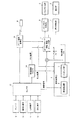
図1で例示する映像表示装置は、信号処理部1、エリアアクティブ制御・輝度ストレッチ部4、バックライト制御部5、バックライト部6、表示制御部7、表示部8、チューナ9、HDMI(High Definition Multimedia Interface)端子10、LAN(Local Area Network)端子11、DVI(Digital Visual Interface)端子12、セレクタ13、映像種類判定部14、およびリモコン信号処理部15を備える。ここで、信号処理部1は、発光検出部2、マッピング部3を備える。なお、本発明の制御部の例としては、バックライト部6と表示部8を制御するものであり、信号処理部1、エリアアクティブ制御・輝度ストレッチ部4、バックライト制御部5、および表示制御部7が該当する。
1 includes a
チューナ9、HDMI端子10、LAN端子11、DVI端子12のいずれかから入力された映像信号は、セレクタ13を介して信号処理部1およびエリアアクティブ制御・輝度ストレッチ部4に入力される。このとき、エリアアクティブ制御・輝度ストレッチ部4への映像信号は、信号処理部1のマッピング部3で生成されたトーンマッピングを適用後、エリアアクティブ制御・輝度ストレッチ部4に入力される。
A video signal input from any of the
まず、映像信号がチューナ9あるいはHDMI端子10を介して入力された場合について説明する。チューナ9の場合、入力映像信号はチューナ9で受信した放送信号から分離した映像信号であり、HDMI端子10の場合、入力映像信号はHDMI端子10にHDMI接続されたレコーダまたはプレーヤ等の再生装置でHDDまたは外部記録媒体(BD,DVDなど)を再生した際の映像信号である。エリアアクティブ制御・輝度ストレッチ部4は、入力された映像信号に従って、映像信号による画像を所定領域に分割し、分割領域ごとに映像信号の最大階調値を抽出する。そしてその抽出した値に基づきバックライト部6の点灯率を計算する。点灯率は、映像の分割領域に対応したバックライト部6の領域ごとに定められるもので、ここで言う点灯率とは後述するように実際には変更されるため、仮の値であると言える。
First, a case where a video signal is input via the
また、バックライト部6は、表示部8を照明するための光源の一例であり、複数のLEDにより構成され、領域ごとに輝度の制御が可能となっている。バックライト部6の領域ごとの点灯率は、予め定められた演算式に基づき決定されるが、基本的に高階調の明るい最大階調値を有する領域では、LEDの輝度を低下させることなく維持し、低階調の暗い最大階調値を有する領域においてLEDの輝度を低下させるような演算を行う。なお、最大階調値の代わりに平均階調値など、入力映像信号の明るさに関連する他の特徴量から点灯率を計算してもよく、平均階調値から計算する場合には、明るい、暗い最大階調値を有する領域の代わりに、それぞれ平均階調値が明るい領域、暗い領域を適用するなどすればよい。
Moreover, the
そして、エリアアクティブ制御・輝度ストレッチ部4は、各領域の点灯率からバックライト部6の全体の平均点灯率を計算し、その平均点灯率に応じて、所定の演算式により、バックライト部6の最大発光輝度のストレッチ量(以下、輝度ストレッチ量)を計算する。バックライト部6の最大発光輝度(LEDの最大発光輝度)をこの輝度ストレッチ量だけストレッチすることで、画面内の全領域で取り得る最大の画面輝度を、基準輝度から所定量だけストレッチすることができる。このストレッチする元となる基準輝度は、例えば最大階調値のときに画面輝度が550(cd/m2)となるような輝度である。この基準の輝度は、この例に限ることなく適宜定めることができる。
Then, the area active control /
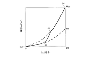
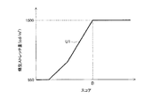
以下、画面内の全領域で取り得る、最大階調値のときのストレッチ後の最大の画面輝度を、「Max輝度」と呼ぶ。上述のように輝度ストレッチ量は平均点灯率により決まる値であり、Max輝度は輝度ストレッチ量により決まる値であるため、図2のグラフで例示するように、Max輝度は平均点灯率に応じて決まる値と言える。なお、図2は、エリアアクティブ制御・輝度ストレッチ部4における処理例を説明するための図で、バックライト部6の平均点灯率(ウィンドウサイズ)に対するMax輝度(cd/m2)の関係を示すグラフの一例を示している。
Hereinafter, the maximum screen luminance after stretching at the maximum gradation value that can be taken in the entire area in the screen is referred to as “Max luminance”. As described above, since the luminance stretch amount is a value determined by the average lighting rate, and the Max luminance is a value determined by the luminance stretch amount, the Max luminance is determined according to the average lighting rate as illustrated in the graph of FIG. Value. FIG. 2 is a diagram for explaining an example of processing in the area active control /
なお、図2のグラフでは、平均点灯率が小さな範囲において、Max輝度が基準輝度(この例では550cd/m2)より小さくなっており、輝度ストレッチ量がマイナスとなっていることを指している。この例のように、平均点灯率によっては輝度ストレッチ量がマイナスとなる場面があったとしても、図2のMax輝度のグラフを全ての平均点灯率に亘って積分した積分値は、基準輝度を全ての平均点灯率に亘って積分した積分値より大きいことから、全体的に見れば最大発光輝度や最大画面輝度(つまり最大表示輝度)が「ストレッチ」により増強されていると言える。 In the graph of FIG. 2, the Max luminance is smaller than the reference luminance (550 cd / m 2 in this example) in a range where the average lighting rate is small, and the luminance stretch amount is negative. . Even if there is a scene where the luminance stretch amount becomes negative depending on the average lighting rate as in this example, the integrated value obtained by integrating the Max luminance graph of FIG. 2 over all the average lighting rates is the reference luminance. Since it is larger than the integral value integrated over all average lighting rates, it can be said that the maximum light emission luminance and the maximum screen luminance (that is, the maximum display luminance) are enhanced by “stretching” as a whole.
エリアアクティブ制御・輝度ストレッチ部4は、平均点灯率に応じて計算した輝度ストレッチ量だけ最大発光輝度がストレッチするように、上記した領域ごとの点灯率(仮の点灯率)を変更する。このような、分割領域ごとの点灯率の計算および平均点灯率に応じた点灯率の変更(ストレッチ後の点灯率の計算)を含む一連の分割領域ごとの点灯率の制御をエリアアクティブ制御と呼ぶ。このように、入力映像信号による画像を複数の領域に分割し、その分割領域の映像信号の階調値に基づいて、その分割領域に対応する光源の領域の点灯率を変化させ、光源の全ての領域について光源の領域の点灯率を平均した平均点灯率を求め、その平均点灯率に予め関係付けられた表示部8の画面上で取り得る最大表示輝度(Max輝度)に基づいて、光源の輝度をストレッチすることが好ましい。
The area active control /
さらに、エリアアクティブ制御・輝度ストレッチ部4は、平均点灯率に応じて決まるMax輝度を、フィードバックのために信号処理部1のマッピング部3に出力する。
Furthermore, the area active control /
信号処理部1の発光検出部2では、入力映像信号の明るさに関係する所定の特徴量に基づくフレームごとのヒストグラムを生成し、発光している部分を検出する。発光している部分は、ヒストグラムの平均値と標準偏差とにより求められるもので、ヒストグラムごとの相対的な値として検出される。このように、発光検出部2は、入力映像信号の明るさに関連する所定の特徴量に対して、画素数を積算したヒストグラムを生成し、そのヒストグラムの所定範囲の上位領域を発光部分として検出する。
The light
入力映像信号のN+1番目のフレームfN+1について説明すると、マッピング部3は、発光検出部2でフレームfN+1について検出された発光部分の情報と、エリアアクティブ制御・輝度ストレッチ部4から出力されたN番目のフレームfNのMax輝度とを使用して、フレームfN+1用のトーンマッピングを生成し、入力映像信号のフレームfN+1に適用するために乗算器に出力する。このトーンマッピングは、フレームfN+1における発光していないとみなす部分(非発光部分)に対して、バックライト部6の輝度ストレッチ分に相当する輝度を低下させるように生成される。この乗算器は、トーンマッピングを入力映像信号に適用するためのものであり、フレームfN+1の映像信号の各画素値に対し、フレームfN+1用のトーンマッピングが示すゲイン係数を乗算して、エリアアクティブ制御・輝度ストレッチ部4に出力する。
The N + 1-th frame f N + 1 of the input video signal will be described. The
また、エリアアクティブ制御・輝度ストレッチ部4は、バックライト部6を制御するための制御データをバックライト制御部5に出力し、バックライト制御部5は、そのデータに基づいてバックライト部6のLEDの発光輝度を分割領域ごとに制御する。この制御データは、上記した領域ごとのストレッチ後の点灯率になるように、バックライト部6を制御するデータである。入力映像信号のフレームfN+1を表示させる際のバックライト部6への制御データは、フレームfNのMax輝度をフィードバックして得たトーンマッピングを適用したフレームfN+1の映像信号について、バックライト部6の領域ごとの点灯率を上記予め定められた演算式に基づき計算した後、ストレッチにより変更することで、得ることができる。バックライト部6のLEDの輝度は、PWM(Pulse Width Modulation)制御で行われるが、電流制御もしくはこれらの組み合わせによって所望の値となるように制御することもできる。
Further, the area active control /
さらに、エリアアクティブ制御・輝度ストレッチ部4は、表示部8を制御するための表示制御データを表示制御部7に出力し、表示制御部7は、その表示制御データに基づいて表示部8の表示を制御する。入力映像信号のフレームfN+1を表示させる際の表示制御データは、フレームfNのMax輝度をフィードバックして得たトーンマッピングをフレームfN+1に適用した後の映像信号について、その映像信号が示す映像を表示するように、表示部8を制御するデータである。表示部8は、バックライト部6のLEDにより照明されて画像を表示する液晶パネルが用いられる。
Further, the area active control /
このように、エリアアクティブ制御・輝度ストレッチ部4では、平均点灯率に応じてバックライト輝度をストレッチしてバックライト部6のLEDの輝度を増大させ、この輝度ストレッチの情報(上記のMax輝度)を信号処理部1に戻して、映像信号に対してバックライト部6の輝度ストレッチ分に相当する輝度を低下させる。そして、輝度ストレッチはバックライト部6の全体に与えられ、映像信号処理による輝度低下は、発光部分を除く発光していないとみなす部分(非発光部分)に対して行われる。
Thus, the area active control /
つまり、エリアアクティブ制御・輝度ストレッチ部4では、バックライト輝度をストレッチしてバックライト部6のLEDの輝度を増大させ、入力映像信号のうち非発光部分の映像信号の輝度を低下させる、といった処理により発光部分の表示輝度をエンハンスする(以下、発光部分エンハンス処理)。このような映像信号処理とバックライトの輝度制御処理とによって、発光している部分のみの画面輝度を増大させ、高いコントラストで映像表現を行うことができ、画質を向上させることができる。
That is, in the area active control /
入力映像信号のうち非発光部分の映像信号の輝度を低下させる処理としては、非発光部分に対してバックライト部6の輝度ストレッチ分に相当する輝度を低下させることが、非発光部分の画面輝度をある程度保つ上で好ましい。すなわち、エリアアクティブ制御・輝度ストレッチ部4は、非発光部分(つまり、所定の特徴量が低い所定領域)において、光源の輝度のストレッチによる表示部8の表示輝度の増加分を、入力映像信号の輝度の低下により低減させることが好ましい。
As processing for reducing the luminance of the video signal of the non-light emitting portion of the input video signal, reducing the luminance corresponding to the luminance stretch of the
本発明の主たる目的は、入力映像信号に対して発光部分エンハンス処理を行い、輝き感およびコントラスト感を高めつつ、WebサイトやPCなどから取得した映像を表示させる場合には、輝き感およびコントラスト感を抑制できるようにすることにある。このための構成として、映像表示装置は、入力映像信号の種類を判定する映像種類判定部14と、本発明の制御部の一例である信号処理部1およびエリアアクティブ制御・輝度ストレッチ部4とを備える。信号処理部1およびエリアアクティブ制御・輝度ストレッチ部4は、映像種類判定部14の判定結果に応じて、発光部分エンハンス処理を実行または停止する。なお、発光部分エンハンス処理とは、上述したように、入力映像信号の明るさに関連する所定の特徴量に対して、画素数を積算したヒストグラムを生成し、ヒストグラムの所定範囲の上位領域を発光部分として検出し、光源の輝度をストレッチして増大させ、入力映像信号のうち発光部分を除く非発光部分の映像信号の輝度を低下させることにより、発光部分の表示輝度をエンハンスするものである。
The main object of the present invention is to perform light emission partial enhancement processing on an input video signal to enhance the shine and contrast while displaying an image acquired from a website or a PC. It is to be able to suppress. As a configuration for this, the video display device includes a video
図1の例において、映像表示装置は、放送信号に含まれる映像信号を入力する本発明の第3の入力部に相当するチューナ9と、レコーダまたはプレーヤ等の再生装置から映像信号を入力する本発明の第4の入力部の一例であるHDMI端子10と、インターネット等のネットワークから映像信号を入力する本発明の第1の入力部の一例であるLAN端子11と、情報処理装置(PC)から映像信号を入力する本発明の第2の入力部の一例であるDVI端子12とを備える。そして、チューナ9またはHDMI端子10から入力される映像信号は主に動画コンテンツに対応したものであり、LAN端子11またはDVI端子12から入力される映像信号は主に静止画コンテンツに対応したものである。
In the example of FIG. 1, the video display device is a
映像種類判定部14は、入力映像信号の種類として、入力映像信号がどの入力ソース、すなわち、チューナ9、HDMI端子10、LAN端子11、DVI端子12のいずれの入力ソースから入力された映像信号であるかを判定する。そして、チューナ9またはHDMI端子10から入力された映像信号は主に動画コンテンツであるため、発光部分エンハンス処理の実行命令を含む判定結果を信号処理部1およびエリアアクティブ制御・輝度ストレッチ部4に出力する。また、LAN端子11またはDVI端子12から入力された映像信号は主に静止画コンテンツであるため、発光部分エンハンス処理の停止命令を含む判定結果を信号処理部1およびエリアアクティブ制御・輝度ストレッチ部4に出力する。
The video
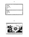
図3は、映像表示装置に表示される静止画コンテンツの一例を示す図である。図3(A)はインターネット上のWebサイトから取得した静止画コンテンツを示し、図3(B)はPCから取得した静止画コンテンツを示す。このような静止画コンテンツに対して、上述の発光部分エンハンス処理を適用した場合、輝き感およびコントラスト感の強い映像となり、かえって見難い映像となる。そこで、信号処理部1およびエリアアクティブ制御・輝度ストレッチ部4は、映像種類判定部14により入力映像信号がLAN端子11またはDVI端子12から入力された映像信号であると判定された場合、発光部分エンハンス処理を停止する。これは、LAN端子11またはDVI端子12から入力される映像信号は主に静止画コンテンツに対応したものであるからである。
FIG. 3 is a diagram illustrating an example of still image content displayed on the video display device. 3A shows still image content acquired from a website on the Internet, and FIG. 3B shows still image content acquired from a PC. When the above-described light emission partial enhancement processing is applied to such still image content, the image has a strong shine and contrast, and is difficult to view. Therefore, the
また、信号処理部1およびエリアアクティブ制御・輝度ストレッチ部4は、映像種類判定部14により入力映像信号がチューナ9またはHDMI端子10から入力された映像信号であると判定された場合、発光部分エンハンス処理を実行する。これは、チューナ9またはHDMI端子10から入力される映像信号は主に動画コンテンツに対応したものであるからである。つまり、入力映像信号の種類を、入力ソース(上記例ではチューナ入力、HDMI入力、LAN入力、DVI入力)によって判定し、LAN入力またはDVI入力の場合に、発光部分エンハンス処理を停止し、チューナ入力またはHDMI入力の場合に、発光部分エンハンス処理を実行する。
Further, the
図1において、入力先として、チューナ9が選択され、ユーザがデジタル放送の番組を視聴している場合を想定する。この場合、チューナ9が選択されているため、発光部分エンハンス処理が実行されている。ここで、例えば、ユーザがインターネット上のWebサイトの映像を見るために、リモコンRを操作してインターネット(LAN端子11)に入力を切り替えるためのリモコン信号を映像表示装置に送信する。映像表示装置のリモコン信号処理部15は、図示しないリモコン受光部を備え、リモコンRから受信したリモコン信号を解析し、LAN端子11に入力を切り替えるようにセレクタ13に指示する。セレクタ13は、リモコン信号処理部15からの指示に従って、LAN端子11を選択し、選択したLAN端子11に入力を切り替える。
In FIG. 1, it is assumed that the
そして、ユーザがリモコンRを操作してWebブラウザを起動させると、映像表示装置はLAN端子11を介してインターネットに接続され、映像表示装置にはインターネット上のWebサイトの映像が表示される。このとき、セレクタ13は、入力先としてLAN端子11が選択されていることを映像種類判定部14に通知し、この通知を受けた映像種類判定部14は、入力映像信号がLAN端子11から入力された映像信号であると判定し、発光部分エンハンス処理の停止命令を含む判定結果を信号処理部1およびエリアアクティブ制御・輝度ストレッチ部4に出力する。
When the user operates the remote controller R to activate the Web browser, the video display device is connected to the Internet via the
信号処理部1およびエリアアクティブ制御・輝度ストレッチ部4は、上記判定結果に応じて、発光部分エンハンス処理を停止する。発光部分エンハンス処理を停止する場合、信号処理部1は、発光検出部2での処理を停止させ、マッピング部3は、例えば、デフォルト設定のトーンマッピング(一例として入出力が1対1に対応したトーンカーブなど)を乗算器に出力する。また、エリアアクティブ制御・輝度ストレッチ部4は、エリアアクティブ制御、輝度ストレッチに係る処理を停止し、入力映像信号に対して、バックライト部6を制御するための制御データをバックライト制御部5に出力すると共に、表示部8を制御するための表示制御データを表示制御部7に出力する。これらの制御データおよび表示制御データとしては、例えば、デフォルト設定のデータを用いることができる。
The
なお、上記のエリアアクティブ制御は、映像を所定の複数の領域(エリア)に分割し、分割領域ごとにLEDの発光輝度を制御するものであるが、発光部分エンハンス処理を停止させた場合でも、このエリアアクティブ制御については実行してもよい。例えば、後述の図4(C)に示すように、分割領域毎に映像信号の最大階調値を抽出し、抽出した最大階調値に応じて領域毎のLEDの点灯率(駆動duty)を決定する。この場合、輝度ストレッチは行わないため、平均点灯率から求めたMax輝度に応じてバックライト輝度をストレッチする処理は停止される。そして、これに伴い、輝度ストレッチの情報(Max輝度)をエリアアクティブ制御・輝度ストレッチ部4から信号処理部1にフィードバックする処理も停止される。
The area active control is to divide the video into a plurality of predetermined areas (areas) and control the light emission luminance of the LED for each divided area, but even when the light emission partial enhancement process is stopped, This area active control may be executed. For example, as shown in FIG. 4C, which will be described later, the maximum gradation value of the video signal is extracted for each divided region, and the LED lighting rate (drive duty) for each region is determined according to the extracted maximum gradation value. decide. In this case, since the luminance stretch is not performed, the process of stretching the backlight luminance according to the Max luminance obtained from the average lighting rate is stopped. Accordingly, the process of feeding back the luminance stretch information (Max luminance) from the area active control /
このように、LAN端子11を介してWebサイトの映像を表示する場合には、発光部分エンハンス処理を停止させることができるため、輝き感およびコントラスト感を抑制した映像を表示することができる。なお、ユーザがPCの映像を見るために、リモコンRを操作してPC(DVI端子12)に入力を切り替えた場合も、同様に、信号処理部1およびエリアアクティブ制御・輝度ストレッチ部4による発光部分エンハンス処理は停止される。
Thus, when displaying the video of the website via the
上述の実施形態では、入力映像信号の種類を、入力ソース(チューナ入力、LAN入力、DVI入力、HDMI入力など)によって判定し、LAN入力またはDVI入力の場合に、発光部分エンハンス処理を停止するようにしていたが、DVI入力であってもPCで動画再生するケースや、LAN入力であってもインターネット上で動画再生するケースなども考えられる。そうすると、ユーザが自身の好みで、発光部分エンハンス処理の実行/停止を切り替えられるようにしておくことが望ましい。例えば、図1のリモコンRに発光部分エンハンス処理の実行/停止を切り替えるための操作ボタンを設けておいてもよい。発光部分エンハンス処理が停止された状態において、リモコン信号処理部15は、リモコンRから発光部分エンハンス処理を実行に切り替えるためのリモコン信号を受信すると、発光部分エンハンス処理を実行するように信号処理部1およびエリアアクティブ制御・輝度ストレッチ部4に指示する。
In the embodiment described above, the type of the input video signal is determined by the input source (tuner input, LAN input, DVI input, HDMI input, etc.), and in the case of LAN input or DVI input, the light emission partial enhancement process is stopped. However, there may be a case in which a moving image is played back on a PC even with DVI input, or a case in which a moving image is played back on the Internet even with LAN input. Then, it is desirable that the user can switch execution / stop of the light emission partial enhancement process according to his / her preference. For example, an operation button for switching execution / stop of the light emission partial enhancement processing may be provided on the remote controller R in FIG. When the light emission partial enhancement processing is stopped, the remote control
また、別の実施形態について説明する。上記のように、LAN入力またはDVI入力の場合であっても、動画コンテンツが入力されることも有り得る。そこで、映像表示装置側で入力映像信号が静止画であるか否かの判定を行うようにしてもよい。具体的には、映像種類判定部14は、入力映像信号がLAN端子11またはDVI端子12から入力された映像信号であると判定した場合、さらに、この入力映像信号が静止画であるか否かを判定する。そして、信号処理部1およびエリアアクティブ制御・輝度ストレッチ部4は、映像種類判定部14により入力映像信号が静止画であると判定された場合、発光部分エンハンス処理を停止する。
Another embodiment will be described. As described above, even in the case of LAN input or DVI input, moving image content may be input. Therefore, the video display device may determine whether or not the input video signal is a still image. Specifically, when the video
上記の静止画判定には、例えば、画素値の差の絶対値の和(SAD:Sum Of Absolute Difference)を用いることができる。このSADは動きベクトルを検出するときの指標の一つであり、2つのフレーム間におけるSADが小さいほど、これら2つのフレームは類似度が高く、静止画とみなすことができる。すなわち、2つのフレーム間でSADを求め、SADが所定値より小さい場合、静止画と判定し、また、SADが所定値以上の場合、動画と判定することができる。 For the still image determination, for example, the sum of absolute values of differences in pixel values (SAD: Sum Of Absolute Difference) can be used. This SAD is one of the indices when detecting a motion vector. The smaller the SAD between two frames, the higher the degree of similarity between these two frames, which can be regarded as a still image. That is, SAD is obtained between two frames. When SAD is smaller than a predetermined value, it is determined as a still image, and when SAD is equal to or greater than a predetermined value, it can be determined as a moving image.
このように、入力ソースの判定に加え、静止画判定を行うことで、より確実に動画と静止画を判別することができるため、動画に対しては発光部分エンハンス処理を実行し、静止画に対しては発光部分エンハンス処理を停止することができる。 In this way, in addition to determining the input source, still image determination makes it possible to more reliably discriminate between a moving image and a still image. On the other hand, the light emission partial enhancement process can be stopped.
以上のような映像表示装置をテレビ受信装置として構成する場合、テレビ受信装置は、アンテナで受信した放送信号を選局して復調し、復号して再生用映像信号を生成する手段(図1のチューナ9に相当)を有し、再生用映像信号に適宜所定の画像処理を施して、図1の入力映像信号として入力させる。これにより、受信した放送信号を表示部8に表示させることができる。本発明は、映像表示装置、およびその映像表示装置を備えるテレビ受信装置として構成することができる。
When the video display device as described above is configured as a television receiving device, the television receiving device selects and demodulates a broadcast signal received by an antenna, decodes it, and generates a playback video signal (FIG. 1). Corresponding to the tuner 9), and appropriately performing predetermined image processing on the reproduction video signal and inputting it as the input video signal of FIG. 1. Thereby, the received broadcast signal can be displayed on the
以下に上記の構成を有する本実施形態の各部の処理例をより具体的に説明する。
図4は、エリアアクティブ制御・輝度ストレッチ部4における平均点灯率の算出処理例を説明するための図であり、図5は、図4のバックライトの平均点灯率と画素の階調値を説明するための図である。
Hereinafter, a processing example of each unit of the present embodiment having the above-described configuration will be described more specifically.
FIG. 4 is a diagram for explaining a calculation process example of the average lighting rate in the area active control /
本発明の実施形態に適用されるエリアアクティブ制御は、映像を所定の複数の領域(エリア)に分割し、その分割した領域に対応するLEDの発光輝度を領域ごとに制御するものである。ここでは、エリアアクティブ制御・輝度ストレッチ部4が、入力映像信号に基づいて、1フレームの映像を予め定められた複数の領域(上記のエリア)に分割し、その分割した領域に対応するLEDの発光輝度をその分割領域ごとに制御する。
Area active control applied to the embodiment of the present invention divides an image into a plurality of predetermined regions (areas), and controls the light emission luminance of the LEDs corresponding to the divided regions for each region. Here, the area active control /
まず、エリアアクティブ制御・輝度ストレッチ部4は、図4(A)に例示するような映像について、図4(B)に示すように全画面の映像領域を縦方向に12分割、横方向に12分割してなる144個の領域に分割する。また、バックライト部6として各領域につき少なくとも1つのLEDが配設されているものとする。
First, the area active control /
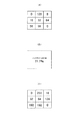
そして、エリアアクティブ制御・輝度ストレッチ部4は、各領域について、映像信号の最大階調値を抽出し、抽出した最大階調値に応じて領域ごとのLEDの仮の点灯率を決定する。上述したように、最大階調値の代わりに、映像信号の階調平均値などの他の明るさに関する特徴量を用いてもよい。この特徴量としては統計値が用いられる。以下、最大階調値を抽出した例により説明する。図4(B)では、各領域について、LEDの点灯率をグレイスケールで図示しており、例えば図4(A)の映像のうち花火があるような階調が高く明るい部分では図4(B)で点灯率を上げて明るくなるようにしている。このときの処理を更に具体的に説明する。
Then, the area active control /
1フレームの各分割領域から最大階調値を抽出したときの様子およびその最大階調値に対応した点灯率の一例を図4(C)に示す。また、図4(D)に各領域の点灯率と画面全体の平均点灯率とを示す。図4(C),(D)では、説明を簡単にするため、1フレームの画面を8つの領域(エリアNo.1〜8)に分割した例を挙げるが、図4(B)のようにより多くの領域に分割して処理することもでき、最大では設けたLEDの数と同じ数の領域に分割して処理できる。 FIG. 4C shows an example of the state when the maximum gradation value is extracted from each divided area of one frame and the lighting rate corresponding to the maximum gradation value. FIG. 4D shows the lighting rate of each area and the average lighting rate of the entire screen. 4 (C) and 4 (D), an example in which the screen of one frame is divided into eight areas (areas Nos. 1 to 8) is given for the sake of simplicity, but as shown in FIG. 4 (B). Processing can be performed by dividing into a large number of regions, and processing can be performed by dividing the region into as many regions as the number of LEDs provided.
まず、エリアNo.1〜8の領域のそれぞれについて、領域内の最大階調値からその領域のバックライトの仮のLEDの点灯率を計算する。仮の点灯率は、例えばLEDの駆動duty(以下、LED duty)によって示すことができる。この場合、点灯率の最大値は100%である。なお、上述したように、LEDの輝度はPWMおよび/または電流制御によって所望の値となるように制御されるが、以下の説明では、説明の簡略化のためにPWM制御のみを採用した例を挙げている。ただし、特に触れないが、輝度ストレッチにより最終的なLED dutyが100%を超えてしまう場合には電流制御を併用して電流値を上げることにより所定の輝度を得るようにすればよい。 First, for each of the areas No. 1 to No. 8, the lighting rate of the temporary LED of the backlight of the area is calculated from the maximum gradation value in the area. The provisional lighting rate can be indicated by, for example, LED drive duty (hereinafter, LED duty). In this case, the maximum value of the lighting rate is 100%. As described above, the brightness of the LED is controlled to be a desired value by PWM and / or current control. In the following description, an example in which only PWM control is employed for the sake of simplification of description. Cite. However, although not particularly touched, when the final LED duty exceeds 100% due to the luminance stretch, a predetermined luminance may be obtained by increasing the current value together with the current control.
各領域のLEDの仮の点灯率の決定においては、最大階調値が低く暗い領域については、点灯率を下げてバックライトの輝度を低下させる。各領域の実際の点灯率は、表示したい階調を正確に表示し、かつLED dutyをできるだけ低くするように決定する。各領域においてLED dutyをできるだけ低くしたいが、表示したい階調をつぶしたりせずに正確に表示する必要があるため、領域内の最大階調が表示でき、なおかつできるだけLED dutyを低くするようなLED duty(仮の点灯率)を設定し、それをもとに表示部8(ここではLCDパネル)の階調を設定する。 In determining the provisional lighting rate of the LED in each region, the luminance of the backlight is lowered by lowering the lighting rate in a dark region where the maximum gradation value is low. The actual lighting rate of each area is determined so that the gradation to be displayed is accurately displayed and the LED duty is made as low as possible. The LED duty in each area is desired to be as low as possible, but it is necessary to display accurately without squashing the gradation to be displayed. Therefore, an LED that can display the maximum gradation in the area and lowers the LED duty as much as possible. The duty (temporary lighting rate) is set, and the gradation of the display unit 8 (here, the LCD panel) is set based on the duty.
一例として、映像の階調値が0−255の8ビットデータで表現される場合で、かつ、図4(C)のうちの1つのエリア内の複数の画素の階調値が図5(A)で示される場合に、ついて説明する。図5(A)で示す画素群では、最大階調値が128であり、この場合には、図5(B)で示すように、そのエリア内でのバックライトの点灯率を(1/(255/128))2.2=0.217倍(21.7%)に低下させる。そして、エリアアクティブ制御・輝度ストレッチ部4は、このような仮の点灯率を決めるとともに、表示部8における画素毎の階調値を、その画素が含まれる領域についての仮の点灯率を考慮して計算すればよい。例えば、表示したい階調値が96の場合、96/(128/255)=192であるため、階調値192を用いて画素を表現すればよい。同様にして、図5(A)の各画素に対して表示させる際の階調値を計算した結果を、図5(C)に示す。
As an example, when the gradation value of the video is expressed by 8-bit data of 0 to 255, the gradation values of a plurality of pixels in one area in FIG. ) Will be described. In the pixel group shown in FIG. 5A, the maximum gradation value is 128. In this case, as shown in FIG. 5B, the lighting rate of the backlight in the area is (1 / ( 255/128)) 2.2 = 0.217 times (21.7%). The area active control /
なお、本発明では、仮の点灯率から求めた平均点灯率に基づき輝度ストレッチを行うため、実際の点灯率は上述の場合の21.7%のままではないが、その輝度ストレッチ分(正しくは前フレームでの輝度ストレッチ分)をマッピング部3によるトーンマッピングで既に反映させ、その結果が上記表示したい階調値(「96」で例示)である。よって、表示制御部7は、図5(A)で示す画素群については、図5(C)で示す階調値の表示制御データで表示部8を表示制御すればよい。
In the present invention, since the luminance stretch is performed based on the average lighting rate obtained from the provisional lighting rate, the actual lighting rate is not 21.7% of the above case, but the luminance stretch portion (correctly, The luminance stretch in the previous frame) is already reflected by the tone mapping by the
図4(C)の例では、グレイスケールで示した各領域の最大階調値に対して、パーセンテージで示したようにバックライトの点灯率が10〜90%の範囲で決定されている。なお、図4(C)のパーセンテージをエリア別に並べたグラフが図4(D)である。この点灯率計算方法はその一例を示すものであるが、基本的には明るい高階調の領域はバックライト輝度を下げることなく、低階調の暗い領域についてバックライトの輝度を低下させるように予め定めた演算式に従って各領域の仮の点灯率を計算する。 In the example of FIG. 4C, the lighting rate of the backlight is determined in the range of 10 to 90% as indicated by the percentage with respect to the maximum gradation value of each region indicated by the gray scale. FIG. 4D is a graph in which the percentages in FIG. 4C are arranged for each area. This lighting rate calculation method shows an example. Basically, a bright high gradation region does not decrease the backlight luminance, and the backlight luminance is decreased in advance in a low gradation dark region. The provisional lighting rate of each area is calculated according to the determined arithmetic expression.
次に、エリアアクティブ制御・輝度ストレッチ部4は、映像信号の最大階調値から計算した領域ごとのバックライトの仮の点灯率を平均して、1フレームにおけるバックライト部6の平均点灯率を計算する。計算された画面全体の平均点灯率は、各領域において点灯率が高い領域が多くなれば当然高くなる。この例では、平均点灯率は、図4(D)に実線で示したようなレベルとなり、実際の値は約53%となる。
Next, the area active control /
実際のバックライト部6の輝度は、平均点灯率に応じて決まる、出し得る最大発光輝度の値(上記したMax輝度に対応する最大発光輝度)に基づいて、つまり上記の輝度ストレッチ量に基づいて、各領域の仮の点灯率をストレッチすることで増強される。
The actual luminance of the
このMax輝度は、取り得る画面輝度の最大値であり、例えば図2のような関係に基づき決定される。図2のグラフにおける横軸は、バックライトの平均点灯率(ウィンドウサイズ)であるが、この平均点灯率は、点灯率100%の点灯領域(ウィンドウ領域)と点灯率0%の消灯領域との比として表すことができる。点灯領域がない状態では平均点灯率はゼロであり、点灯領域のウィンドウが大きくなるに従って平均点灯率は増大し、全点灯では平均点灯率は100%になる。 This Max luminance is the maximum screen luminance that can be taken, and is determined based on the relationship shown in FIG. 2, for example. The horizontal axis in the graph of FIG. 2 is the average lighting rate (window size) of the backlight, and this average lighting rate is calculated between a lighting region (window region) with a lighting rate of 100% and a non-lighting region with a lighting rate of 0%. It can be expressed as a ratio. The average lighting rate is zero when there is no lighting region, the average lighting rate increases as the window of the lighting region increases, and the average lighting rate becomes 100% for all lighting.
図2では、バックライトが全点灯(平均点灯率100%)のときのMax輝度を例えば、550(cd/m2)とし、これをストレッチ前の基準輝度とする。そして本実施形態では、平均点灯率が100%から下がっていくに従って、Max輝度を増大させる。なお、8ビット表現の場合、階調値が255階調の画素が画面内で最も画面輝度が高くなり、取り得る最大の画面輝度(Max輝度)になる。このことから、同じ平均点灯率であっても、画素の階調値によってはMax輝度まで画面輝度が上がらないことがわかる。
In FIG. 2, the Max luminance when the backlight is fully lit (
図2では、平均点灯率がPのときに、Max輝度の値は最も大きくなり、このときの最大の画面輝度は1500(cd/m2)となる。つまりPのときには、取り得る最大の画面輝度は、全点灯時の550(cd/m2)に比較して1500(cd/m2)までストレッチされることになる。Pは、比較的平均点灯率が低い位置に設定されている。つまり全体に暗い画面で平均点灯率が低く、かつ一部に高階調のピークがあるような画面のときに、最高で1500(cd/m2)になるまでバックライトの輝度がストレッチされる。 In FIG. 2, when the average lighting rate is P, the value of Max luminance is the largest, and the maximum screen luminance at this time is 1500 (cd / m 2 ). In other words, at P, the maximum possible screen brightness is stretched to 1500 (cd / m 2 ) compared to 550 (cd / m 2 ) when all the lights are on. P is set at a position where the average lighting rate is relatively low. In other words, the brightness of the backlight is stretched to a maximum of 1500 (cd / m 2 ) when the screen is a dark screen as a whole with a low average lighting rate and a high gradation peak in part.
また、高い平均点灯率のときほど、バックライトの輝度のストレッチの程度が小さい理由としては、もともと明るい画面ではバックライトの輝度を過度に行うと却って眩しく感じることがあるため、ストレッチの程度を抑えるようにするためである。 Also, the reason for the lower stretch of backlight brightness is the higher the average lighting rate, the less bright the screen is because it may feel dazzling if the backlight brightness is excessively high on an originally bright screen. It is for doing so.
また、平均点灯率が低い範囲は、暗い画面の映像に相当するものであり、バックライトの輝度をストレッチして画面輝度を上げるよりも、逆にバックライトの輝度を抑えてコントラストを向上させ、黒浮きを抑えて表示品位を保つことが好ましい。よって、図2の例では、このような低平均点灯率における黒浮き抑制のための設定を採用し、平均点灯率Pから平均点灯率0(全黒)まではMax輝度の値を徐々に低下させている。 In addition, the range with a low average lighting rate corresponds to a dark screen image, and rather than increasing the screen brightness by stretching the backlight brightness, the backlight brightness is reduced to improve the contrast, It is preferable to maintain the display quality by suppressing black float. Therefore, in the example of FIG. 2, such a setting for suppressing black floating at the low average lighting rate is adopted, and the value of Max luminance is gradually decreased from the average lighting rate P to the average lighting rate 0 (all black). I am letting.
エリアアクティブ制御・輝度ストレッチ部4は、図2の曲線に従って、バックライトの輝度をストレッチし、その制御信号をバックライト制御部5に出力する。ここでは上記のように映像の分割領域ごとに検出される最大階調値に応じて平均点灯率が変化し、その平均点灯率に応じて輝度ストレッチの状態が変化する。
The area active control /
エリアアクティブ制御・輝度ストレッチ部4に入力する映像信号は、以下に説明する信号処理部1による信号処理により生成されたトーンマッピングが適用され、低階調領域がゲインダウンされて入力される。これにより、低階調の非発光領域ではバックライトの輝度がストレッチされた分、映像信号のゲインダウンによって輝度が低減され、結果として発光している領域のみで画面輝度がエンハンスされ、輝き感が増すようになっている。
The video signal input to the area active control /
エリアアクティブ制御・輝度ストレッチ部4は、図2の曲線に従ってバックライトの平均点灯率から求めたMax輝度の値を、信号処理部1のマッピング部3に出力する。そして、エリアアクティブ制御・輝度ストレッチ部4から出力されたMax輝度を使用して、マッピング部3がトーンマッピングを行う。
The area active control /
信号処理部1について説明する。
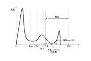
信号処理部1の発光検出部2では、映像信号から発光している部分を検出する。図6は、入力映像信号の輝度信号Yから生成したYヒストグラムの例を示す図である。発光検出部2では、入力した映像信号のフレームごとに、輝度階調ごとの画素数を積算してYヒストグラムを生成する。横軸は輝度Yの階調値で、縦軸は階調値ごとに積算した画素数(頻度)を示している。ここでは、輝度Yについて発光部分を検出するものとする。輝度Yは、発光部分を検出するためのヒストグラムを作成する映像の特徴量の一例であり、特徴量の他の例については後述する。
The
The light
Yヒストグラムが生成されると、そのYヒストグラムから平均値(Ave)、標準偏差(σ)を計算し、これらを用いて2つの閾値Thを計算する。
第2の閾値Th2は、発光境界を定めるものであり、Yヒストグラムにおいてこの閾値Th2以上の画素は、発光している部分であるものとみなして処理を行う。第2の閾値Th2は、Nを所定の定数、σを標準偏差として、下式(1)で表すことができる。つまり、発光検出部2では、下式(1)のTh2以上の画素を発光部分として検出する。
Th2 = Ave+Nσ ・・・式(1)
When the Y histogram is generated, an average value (Ave) and a standard deviation (σ) are calculated from the Y histogram, and two threshold values Th are calculated using these.
The second threshold value Th2 defines a light emission boundary, and processing is performed on the assumption that pixels above the threshold value Th2 in the Y histogram are light emitting portions. The second threshold Th2 can be expressed by the following equation (1), where N is a predetermined constant and σ is a standard deviation. That is, the light
Th2 = Ave + Nσ Expression (1)
また、第1の閾値Th1は、Th2より小さい領域の階調性などの違和感を抑えるために設定されるもので、MをM<Nを満たす所定の定数として、下式(2)で表すことができる。
Th1 = Ave+Mσ ・・・式(2)
発光検出部2が検出した第1および第2の閾値Th1,Th2の値は、マッピング部3に出力され、トーンマッピングの生成に使用される。
The first threshold value Th1 is set to suppress a sense of incongruity such as gradation in a region smaller than Th2, and is expressed by the following expression (2), where M is a predetermined constant that satisfies M <N. Can do.
Th1 = Ave + Mσ Expression (2)
The values of the first and second threshold values Th1 and Th2 detected by the light
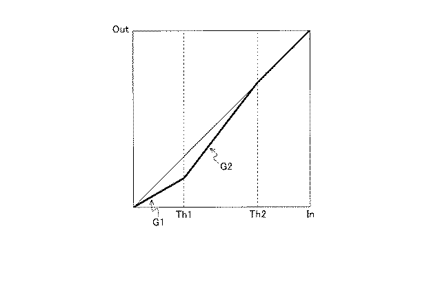
図7は、マッピング部3が生成するトーンマッピングの一例を示す図である。図7において、横軸は映像の輝度値の入力階調で、縦軸は出力階調である。発光検出部2で検出された第2の閾値Th2以上の画素については、映像の中で発光している部分であり、発光している部分を除いて圧縮ゲインを適用してゲインダウンする。このときに、発光境界であるTh2より小さい領域に一律に一定の圧縮ゲインを適用して出力階調を抑えると、階調性に違和感が生じる。従って、発光検出部2にて第1の閾値Th1を設定して検出し、Th1より小さい領域に対して第1のゲインG1を設定し、Th1とTh2の間を線形で結ぶように第2のゲインG2を設定してトーンマッピングを行う。
FIG. 7 is a diagram illustrating an example of tone mapping generated by the
ゲインの設定方法について説明する。
マッピング部3には、エリアアクティブ制御・輝度ストレッチ部4からMax輝度の値が入力される。Max輝度は、上述したように、バックライトの平均点灯率から定められる最大画面輝度を示すもので、例えばそれに対応する、最大発光輝度を示すバックライトデューティ(LED duty)の値を入力することができる。
A method for setting the gain will be described.
The
第1のゲインG1は、第1の閾値Th1より小さい領域に適用されるもので、下式(3)により設定される。
G1=(Ls/Lm)1/γ ・・・式(3)
ここで、Lsは、基準輝度(バックライト輝度をストレッチしないときの基準輝度;一例として最大の画面輝度が550cd/m2となるときの輝度)であり、Lmは、エリアアクティブ制御・輝度ストレッチ部4から出力されたMax輝度である。従って、第1の閾値Th1より小さい領域に適用される第1のゲインG1は、バックライトの輝度ストレッチにより増加する画面輝度分を低減させるように、映像信号の出力階調を低下させる。
The first gain G1 is applied to a region smaller than the first threshold Th1, and is set by the following expression (3).
G1 = (Ls / Lm) 1 / γ Expression (3)
Here, Ls is the reference luminance (reference luminance when the backlight luminance is not stretched; for example, the luminance when the maximum screen luminance is 550 cd / m 2 ), and Lm is the area active control / luminance stretching unit. Max luminance output from 4. Therefore, the first gain G1 applied to the region smaller than the first threshold Th1 lowers the output gradation of the video signal so as to reduce the screen luminance that increases due to the luminance stretch of the backlight.
第2の閾値Th2以上のトーンマッピングは、f(x)=xとする。つまり、入力階調=出力階調とし、出力階調を低下させる処理は行わない。第1の閾値Th1〜第2の閾値Th2までの間は、第1のゲインG1によって低下させた第1の閾値Th1の出力階調と、第1の閾値Th1の出力階調とを直線で結ぶように設定する。つまり、G2=(Th2−G1・Th1)/(Th2−Th1)によって第2のゲインG2を決定する。
上記の処理により、図7に示すようなトーンマッピングを得る。このときに、Th1、Th2の接続部分については、所定の範囲(例えば接続部分±Δ(Δは所定値))を2次関数でスムージングするとよい。
For tone mapping of the second threshold Th2 or more, f (x) = x. That is, input gradation = output gradation, and processing for lowering the output gradation is not performed. Between the first threshold Th1 and the second threshold Th2, the output gradation of the first threshold Th1 lowered by the first gain G1 and the output gradation of the first threshold Th1 are connected by a straight line. Set as follows. That is, the second gain G2 is determined by G2 = (Th2-G1 · Th1) / (Th2-Th1).
Through the above processing, tone mapping as shown in FIG. 7 is obtained. At this time, with respect to the connecting portions of Th1 and Th2, a predetermined range (for example, connecting portion ± Δ (Δ is a predetermined value)) may be smoothed by a quadratic function.
マッピング部3が生成したトーンマッピングは入力映像信号に適用され、バックライトの輝度ストレッチ量に基づき低階調部分の出力が抑えられた映像信号がエリアアクティブ制御・輝度ストレッチ部4に入力される。
The tone mapping generated by the
図8は、エリアアクティブ制御・輝度ストレッチ部4で出力するフレームfN,fN+1のMax輝度について説明するための図である。なお、図8で示すグラフは、図2で示したグラフと同じである。
FIG. 8 is a diagram for explaining the Max luminance of the frames f N and f N + 1 output from the area active control /
エリアアクティブ制御・輝度ストレッチ部4は、上述したように、マッピング部3で生成したトーンマッピングを適用した映像信号を入力し、その映像信号に基づいてエリアアクティブ制御を行い、平均点灯率に基づくMax輝度の決定も行う。このときのフレームをフレームfNとする。フレームfNのMax輝度の値は、マッピング部3に出力される。マッピング部3では、入力したフレームfNのMax輝度を使用して図7に示すようなトーンマッピングを生成し、フレームfN+1の映像信号に適用する。
As described above, the area active control /
こうして、本実施形態では、エリアアクティブ制御の平均点灯率に基づくMax輝度をフィードバックして、次のフレームのトーンマッピングに使用する。マッピング部3は、フレームfNで決定されたMax輝度に基づいて、図7で説明したように、第1の閾値Th1より小さい領域について映像出力を低下させるゲイン(第1のゲインG1)を適用する。Th1とTh2の間の領域についてTh1とTh2の間を線形で結ぶ第2のゲインG2を適用してTh1とTh2の間の映像出力を低下させる。
Thus, in this embodiment, Max luminance based on the average lighting rate of area active control is fed back and used for tone mapping of the next frame.
図8の例では、平均点灯率がP以上の高点灯率の領域において、フレームfNで非発光部分の映像出力を低下させるゲインが適用されているため、フレームfN+1では、領域ごとの最大階調値が低下して点灯率が下がる傾向となり、これにより、フレームfN+1では、Max輝度が上がる傾向となる。これにより、フレームfN+1ではさらにバックライトの輝度ストレッチ量が大きくなって、画面の輝き感が増す傾向となる。ただし、この傾向はPより低点灯率の領域では見られず、逆の傾向となる。 In the example of FIG. 8, the average lighting rate is not less than the high lighting rate region P, the gain to reduce the video output of the non-light emitting portion in the frame f N is applied, the frame f N + 1, the maximum per area The gradation value tends to decrease and the lighting rate tends to decrease. As a result, Max luminance tends to increase in the frame f N + 1 . As a result, in the frame fN + 1 , the luminance stretch amount of the backlight is further increased, and the brightness of the screen tends to increase. However, this tendency is not seen in the region where the lighting rate is lower than P, and the reverse tendency occurs.
図9は、エリアアクティブ制御・輝度ストレッチ部4の処理により、画面輝度がエンハンスされる状態を示す図である。図9において、横軸は入力映像信号の階調値で、縦軸は表示部8の画面輝度(cd/m2)であり、S2,S3は、それぞれ発光検出部2で使用した第1および第2閾値Th1,Th2の階調値の位置に相当する。
FIG. 9 is a diagram illustrating a state in which the screen luminance is enhanced by the processing of the area active control /
上記のように発光検出部2で検出した第2の閾値Th2以上の領域では、バックライトの輝度ストレッチ量に応じて映像信号の出力階調を低下させる信号処理が行われていない。この結果、S3〜S4では、入力映像信号は、エリアアクティブ制御により決定されたMax輝度に従うγカーブでエンハンスされて表示される。S4は入力映像信号が最高階調値(255)であるときの画面輝度を示しており、例えばMax輝度が1500(cd/m2)である場合、最高階調での画面輝度は1500(cd/m2)となる。
As described above, in the region equal to or greater than the second threshold Th2 detected by the light
一方、S1〜S2までの入力階調値の場合には、上記のように、バックライトの輝度ストレッチにより増加する画面輝度分を低減させるように第1のゲインG1が映像信号に適用されているため、基準輝度に基づくγカーブで画面表示される。エリアアクティブ制御・輝度ストレッチ部4で決定されたMax輝度に従って、マッピング部3で輝度ストレッチ分に対応して、閾値Th1(S2に相当)より小さい範囲で映像信号の出力値を抑えたからである。S2〜S3は、Th1〜Th2のトーンマッピングに応じて画面輝度が遷移する。
On the other hand, in the case of input gradation values from S1 to S2, as described above, the first gain G1 is applied to the video signal so as to reduce the screen luminance component that increases due to the luminance stretch of the backlight. Therefore, the screen is displayed with a γ curve based on the reference luminance. This is because the output value of the video signal is suppressed in a range smaller than the threshold Th1 (corresponding to S2) corresponding to the luminance stretch by the
Max輝度が大きくなると、S1〜S2の基準輝度に基づく曲線と、S3〜S4のMax輝度に基づく曲線との画面輝度方向の差が大きくなる。基準輝度に基づく曲線は、前述のように、最大階調値の画面輝度が、バックライト輝度をストレッチしないときの基準輝度(一例として最大階調値の画面輝度が550cd/m2)となるγカーブであり、Max輝度に基づく曲線は、最大階調値の画面輝度が、エリアアクティブ制御・輝度ストレッチ部4で決定されたMax輝度となるγカーブである。
When the Max luminance increases, the difference in the screen luminance direction between the curve based on the reference luminance of S1 to S2 and the curve based on the Max luminance of S3 to S4 increases. As described above, the curve based on the reference brightness indicates that the maximum brightness value screen brightness is the reference brightness when the backlight brightness is not stretched (for example, the maximum brightness value screen brightness is 550 cd / m 2 ). The curve based on the Max luminance is a γ curve in which the screen luminance of the maximum gradation value becomes the Max luminance determined by the area active control /
こうして、入力映像信号が0階調(S1)からS2までの間では、基準輝度で画面輝度を制御する。階調が低く暗い映像の場合には、輝度を上げて表示させるとコントラストの低下や黒浮き等の品位低下が生じるため、バックライトの輝度ストレッチ分だけ映像信号処理により輝度を抑えて画面輝度が上がらないようにする。 In this way, when the input video signal is between 0 gradation (S1) and S2, the screen brightness is controlled with the reference brightness. In the case of dark images with low gradation, if the brightness is increased and displayed, the image quality will be reduced by the video signal processing by the amount of the backlight brightness stretch. Try not to go up.
また、入力映像信号がS3以上の範囲は、発光しているとみなしている範囲であるので、輝度ストレッチによりバックライトをストレッチした状態で、映像信号を抑えることなく維持する。これにより、画面輝度がエンハンスされ、より輝き感のある高品位の画像表示を行うことができる。なお、S1〜S2までのγカーブは、基準輝度に一致させる必要はなく、発光部分のエンハンス領域との差を持たせるレベルのものであれば、ゲインG1を適宜調整して設定することができる。 In addition, since the range where the input video signal is greater than or equal to S3 is a range that is considered to emit light, the video signal is maintained without being suppressed while the backlight is stretched by luminance stretching. Thereby, the screen brightness is enhanced, and a high-quality image display with a more lustrous feeling can be performed. The γ curves from S1 to S2 do not need to match the reference luminance, and can be set by appropriately adjusting the gain G1 as long as it has a level different from the enhancement region of the light emitting portion. .
(実施形態2)
図10は、本発明に係る映像表示装置の他の実施形態(実施形態2)を説明するための図で、映像表示装置の要部の他の構成例を示すものである。
(Embodiment 2)
FIG. 10 is a diagram for explaining another embodiment (Embodiment 2) of the video display device according to the present invention, and shows another configuration example of the main part of the video display device.
実施形態2は、実施形態1と同様の構成を有しているが、実施形態1と異なり、トーンマッピングを行う際に用いるMax輝度の値をエリアアクティブ制御・輝度ストレッチ部4で決定することなく、発光検出部2が発光部分の検出結果に基づき輝度ストレッチ量を決定し、マッピング部3がその決定した輝度ストレッチ量に基づいてトーンマッピングを実行する。従って、信号処理部1のマッピング部3では、実施形態1のように、輝度ストレッチによるMax輝度値をエリアアクティブ制御・輝度ストレッチ部4から出力させる必要はない。無論、発光検出部2では発光部分の検出のみを行い、マッピング部3を、発光部分の検出結果から輝度ストレッチ量を計算するように構成してもよい。
The second embodiment has the same configuration as that of the first embodiment, but unlike the first embodiment, the Max luminance value used for tone mapping is not determined by the area active control /
図11は、入力映像信号の輝度信号Yから生成したYヒストグラムの例を示すものである。実施形態1と同様に、発光検出部2では、入力した映像信号のフレームごとに、画素の輝度階調ごとの画素数を積算してYヒストグラムを生成する。そしてそのYヒストグラムから平均値(Ave)、標準偏差(σ)を計算し、これらを用いて2つの閾値Th1,Th2を計算する。実施形態1と同様に、第2の閾値Th2は、発光境界を定めるものであり、Yヒストグラムにおいてこの閾値Th2以上の画素は、発光している部分であるものとみなすものである。
FIG. 11 shows an example of a Y histogram generated from the luminance signal Y of the input video signal. As in the first embodiment, the light
本実施形態では、さらに第3の閾値Th3を設定する。第3の閾値Th3は、Th1とTh2の間にあり、発光部分の画素の状態を検出するために設けられる。閾値Th3は、Th2と同じ値でもよいが、Th2以上の発光部分にマージンを持たせて広めにとり、処理を行いやすくするために設けられている。従って、Th3は下式(4)のようになる。
Th3 = Ave+Qσ(M<Q≦N) ・・・式(4)
In the present embodiment, a third threshold Th3 is further set. The third threshold value Th3 is between Th1 and Th2, and is provided for detecting the state of the pixel in the light emitting portion. The threshold value Th3 may be the same value as Th2, but is provided in order to facilitate processing by providing a wider margin for the light emitting portion equal to or greater than Th2. Accordingly, Th3 is expressed by the following equation (4).
Th3 = Ave + Qσ (M <Q ≦ N) (4)
図12は、第3の閾値Th3以上の画素に応じた輝度ストレッチの設定例を示す図である。横軸は閾値Th3以上の画素値のスコア、縦軸はスコアに応じた輝度ストレッチ量を示している。
スコアは、[輝度がある閾値より大きい画素の割合]×[閾値からの距離(輝度の差)]と定義し、第3の閾値Th3より大きい階調値を持つ画素の画素数をカウントし、閾値Th3からの距離に重み付けをして算出することにより明るさの度合いを示すもので、例えば、下式(5)により計算される。
The score is defined as [ratio of pixels with luminance greater than a certain threshold] × [distance from threshold (luminance difference)], and counts the number of pixels having a gradation value larger than the third threshold Th3, The degree of brightness is indicated by weighting and calculating the distance from the threshold Th3. For example, it is calculated by the following equation (5).
式(5)において、count[i]は、階調値iごとに画素数をカウントした値である。また、i2−(Th3)2は、図11で示したような輝度についての距離(輝度の差)を指し、代わりに、明度L*における閾値からの距離を採用してもよい。なお、この2乗は輝度を表すものであり、実際には2.2乗となる。つまり、デジタルのコード値がiの場合、輝度はi2.2となる。そのとき、明度L*は(i2.2)1/3≒iとなる。実際の映像表示装置で検証した結果、輝度での閾値からの差が明度での閾値からの差などより効果的であった。また、式(5)において、全画素数とはi>Th3に限らず全ての画素数をカウントした値を指す。スコアとしてこのような計算値を採用すると、発光部分のうちTh3から離れた高階調の画素が多い場合にはスコアが高くなる。また、Th3より大きな画素数が一定であっても、階調が高い画素が多い方がスコアは高くなる。 In equation (5), count [i] is a value obtained by counting the number of pixels for each gradation value i. Further, i 2 − (Th3) 2 indicates the distance (brightness difference) with respect to the luminance as shown in FIG. 11, and instead, the distance from the threshold value in the lightness L * may be adopted. Note that this square represents the luminance and is actually the 2.2th power. That is, when the digital code value is i, the luminance is i 2.2 . At that time, the lightness L * is (i 2.2 ) 1/3 ≈ i. As a result of verification with an actual video display device, the difference from the threshold value in luminance was more effective than the difference from the threshold value in brightness. In Equation (5), the total number of pixels is not limited to i> Th3, but is a value obtained by counting all the numbers of pixels. When such a calculated value is adopted as the score, the score increases when there are many high gradation pixels apart from Th3 in the light emitting portion. Even if the number of pixels larger than Th3 is constant, the score is higher as the number of pixels with higher gradation is larger.
そして、図12のグラフU1で示すように、スコアが一定以上に高いレベルでは、輝度ストレッチ量を高く設定し、高階調の輝いている映像をより高輝度にストレッチして輝き感を増す。この例では、スコアが一定以上(閾値B以上)の高い部分では、輝度ストレッチ後に取りうる最大の画面輝度が1500(cd/m2)となるように設定する。また、スコアが低い場合には、スコアが小さくなるほど輝度ストレッチ量が小さくなるように設定する。 Then, as shown by a graph U1 in FIG. 12, when the score is higher than a certain level, the luminance stretch amount is set high, and a high gradation shining image is stretched to a higher luminance to increase the shine. In this example, the maximum screen luminance that can be obtained after luminance stretching is set to 1500 (cd / m 2 ) in a portion where the score is higher than a certain value (threshold B or higher). When the score is low, the luminance stretch amount is set to be smaller as the score is smaller.
輝度ストレッチ量は、実施形態1で説明したものであって、Max輝度と同様に例えばバックライトデューティの値によって示されるものである。発光検出部2が検出した第1および第2の閾値Th1,Th2の値、およびTh3以上の画素のスコアに従って決定される輝度ストレッチ量は、マッピング部3に出力され、トーンマッピングの生成に使用される。
The luminance stretch amount is the same as that described in the first embodiment, and is indicated by, for example, the value of the backlight duty similarly to the Max luminance. The luminance stretch amount determined according to the values of the first and second threshold values Th1 and Th2 detected by the light
マッピング部3におけるトーマッピングの処理は、実施形態1と同様である。つまり図7に示すように、発光検出部2にて検出したTh1より小さい領域に対して第1のゲインG1を設定し、Th1とTh2の間を線形で結ぶように第2のゲインG2を設定する。このときに、ゲインG1の設定に際して、発光検出部2で検出した輝度ストレッチ量を使用し、バックライトの輝度ストレッチ量に応じて映像信号処理により輝度を低下させる。
得られたトーンマッピングは、入力映像信号に適用され、エリアアクティブ制御・輝度ストレッチ部4に入力する。
The toe mapping process in the
The obtained tone mapping is applied to the input video signal and input to the area active control /
エリアアクティブ制御・輝度ストレッチ部4における処理は、実施形態1と同様である。ただし、エリアアクティブ制御・輝度ストレッチ部4では、実施形態1のようにバックライトの平均点灯率からMax輝度を決定し、信号処理部1に出力する必要はなく、逆に信号処理部1の発光検出部2で検出された輝度ストレッチ量に基づいてバックライト部6のLEDの輝度をストレッチする。
The processing in the area active control /
つまり、エリアアクティブ制御・輝度ストレッチ部4では、映像を所定の複数の領域(エリア)に分割し、その分割領域ごとに映像信号の最大階調値を抽出し、抽出した最大階調値に応じて領域ごとのLEDの点灯率を決定する。例えば最大階調値が低く暗い領域については、点灯率を下げてバックライトの輝度を低下させる。そして、この状態で輝度ストレッチ量に応じてバックライト全体の投入電力を増大させて、バックライトの輝度全体をUPする。これにより、発光している明るい映像はより明るくなって輝き感が増す。また、非発光部分は、映像信号処理により輝度ストレッチに相当する輝度が低減されているため、結果として、画面上では発光部分のみの輝度が高くなって、高コントラストの品位の高い映像を表示することができる。入力映像信号と画面輝度との関係は、実施形態1に示す図9と同様になる。
That is, the area active control /
このように、発光検出部2では、検出した発光部分の領域を含む所定範囲(上述の例ではTh3以上の範囲)の映像について、画素ごとの明るさに重みを付けて画素数をカウントすることにより明るさの度合いを示すスコアを計算し、そのスコアに応じて輝度ストレッチ量を決め、エリアアクティブ制御・輝度ストレッチ部4でその輝度ストレッチ量でストレッチされるようにする。そのため、輝度ストレッチ量はエリアアクティブ制御・輝度ストレッチ部4とマッピング部3に出力される。エリアアクティブ制御・輝度ストレッチ部4は、輝度ストレッチ量に応じて輝度をストレッチする。マッピング部3は、輝度ストレッチ量に応じてゲインカーブを変えるなどして、ストレッチした輝度を映像信号処理により低下させる。
As described above, the light
そして、信号処理部1およびエリアアクティブ制御・輝度ストレッチ部4は、実施形態2の発光部分エンハンス処理を、映像種類判定部14の判定結果に応じて、実行または停止する。本発明に係る映像種類判定部14の構成は実施形態1と同様であるため、ここでの繰り返しの説明は省略する。
Then, the
発光部分エンハンス処理を停止する場合、信号処理部1は、発光検出部2での処理を停止させるため、輝度ストレッチ量(N)は算出されず、マッピング部3およびエリアアクティブ制御・輝度ストレッチ部4に輝度ストレッチ量(N)が出力されることはない。この場合、マッピング部3は、例えば、デフォルト設定のトーンマッピング(一例として入出力が1対1に対応したトーンカーブなど)を乗算器に出力する。また、エリアアクティブ制御・輝度ストレッチ部4は、エリアアクティブ制御、輝度ストレッチに係る処理を停止し、入力映像信号に対して、バックライト部6を制御するための制御データをバックライト制御部5に出力すると共に、表示部8を制御するための表示制御データを表示制御部7に出力する。これらの制御データおよび表示制御データとしては、例えば、デフォルト設定のデータを用いることができる。
When the light emission partial enhancement process is stopped, the
なお、上記のエリアアクティブ制御については実施形態1と同様に実行してもよい。例えば、前述の図4(C)に示すように、分割領域毎に映像信号の最大階調値を抽出し、抽出した最大階調値に応じて領域毎のLEDの点灯率(駆動duty)を決定する。この場合、輝度ストレッチは行わないため、平均点灯率から求めたMax輝度に応じてバックライト輝度をストレッチする処理は停止される。 The area active control may be executed in the same manner as in the first embodiment. For example, as shown in FIG. 4C described above, the maximum gradation value of the video signal is extracted for each divided region, and the lighting rate (drive duty) of the LED for each region is determined according to the extracted maximum gradation value. decide. In this case, since the luminance stretch is not performed, the process of stretching the backlight luminance according to the Max luminance obtained from the average lighting rate is stopped.
(実施形態3)
図13は、本発明に係る映像表示装置の更に他の実施形態(実施形態3)を説明するための図で、映像表示装置の要部の更に他の構成例を示すものである。
(Embodiment 3)
FIG. 13 is a view for explaining still another embodiment (Embodiment 3) of the video display apparatus according to the present invention, and shows still another configuration example of the main part of the video display apparatus.
実施形態3は、実施形態2と同様の構成を有し、実施形態2と同様の動作を行うが、実施形態2と異なり、エリアアクティブ制御・輝度ストレッチ部4の代わりに、エリアアクティブ制御を行わない輝度ストレッチ部4aを備える。この輝度ストレッチ部4aでは、信号処理部1のマッピング部3から出力された輝度ストレッチ量に基づいて、バックライト部6の輝度をストレッチする。
The third embodiment has the same configuration as that of the second embodiment and performs the same operation as that of the second embodiment. However, unlike the second embodiment, the area active control is performed instead of the area active control /
つまり輝度ストレッチ部4aでは、マッピング部3により生成されたトーンマッピングが適用された映像信号を入力し、その映像信号を表示する表示制御データを表示制御部7に出力する。このときにエリアアクティブ制御による処理は行わない。一方、マッピング部3から出力された輝度ストレッチ量に基づいてバックライト部6全体を一律にストレッチする。
That is, the luminance stretch unit 4 a receives the video signal to which the tone mapping generated by the
これにより、発光している明るい映像はより明るくなって輝き感が増す。また、非発光部分は、映像信号処理により輝度ストレッチに相当する輝度が低減されているため、結果として、画面上では発光部分の輝度が高くなって、高コントラストの品位の高い映像を表示することができる。 As a result, the bright image that is emitted becomes brighter and more radiant. In addition, since the luminance corresponding to the luminance stretch is reduced by the video signal processing in the non-light emitting part, as a result, the luminance of the light emitting part is increased on the screen, and high contrast and high quality images are displayed. Can do.
そして、信号処理部1および輝度ストレッチ部4aは、実施形態3の発光部分エンハンス処理を、映像種類判定部14の判定結果に応じて、実行または停止する。本発明に係る映像種類判定部14の構成は実施形態1、2と同様であるため、ここでの繰り返しの説明は省略する。発光部分エンハンス処理を停止する場合、信号処理部1は、発光検出部2での処理を停止させるため、輝度ストレッチ量(N)は算出されず、マッピング部3および輝度ストレッチ部4aに輝度ストレッチ量(N)が出力されることはない。
Then, the
この場合、マッピング部3は、例えば、デフォルト設定のトーンマッピング(一例として入出力が1対1に対応したトーンカーブなど)を乗算器に出力する。また、輝度ストレッチ部4aは、輝度ストレッチに係る処理を停止し、入力映像信号に対して、バックライト部6を制御するための制御データをバックライト制御部5に出力すると共に、表示部8を制御するための表示制御データを表示制御部7に出力する。これらの制御データおよび表示制御データとしては、例えば、デフォルト設定のデータを用いることができる。
In this case, the
なお、前述の実施形態1において、図1のエリアアクティブ制御・輝度ストレッチ部4の代わりに、同様にエリアアクティブ制御を実行しない輝度ストレッチ部4aを設けるようにしてもよい。そのような構成の場合、輝度ストレッチ部4aで平均点灯率(ただし、この例では仮の点灯率自体が画面全体の仮の平均点灯率である)からMax輝度を求め、それに基づきLEDの発光輝度を上げると共に、そのMax輝度をマッピング部3にフィードバックすればよい。
In the first embodiment, instead of the area active control /
(他の特徴量)
上記の各例では、発光検出部2における発光部分の検出処理において、映像の特徴量として輝度Yを使用し、輝度のヒストグラムを生成してその中から発光部分を検出していた。しかし、ヒストグラムを生成する特徴量としては、輝度の他、例えばCMI(Color Mode Index)、もしくは、1つの画素を構成するRGBの映像信号の階調値のうち最も高い階調値(Max RGBとする)を用いることができる。
(Other features)
In each of the above examples, in the light emission portion detection processing in the light
CMIは、注目する色がどの程度明るいかを示す指標である。ここではCMIは輝度とは異なり、色の情報も加味された明るさを示している。CMIは、下式(6)により定義される。
(L*/L*modeboundary)×100 ・・・式(6)
CMI is an index indicating how bright the color of interest is. Here, the CMI is different from the luminance, and indicates the brightness in consideration of the color information. CMI is defined by the following equation (6).
(L * / L * modeboundary) × 100 (6)
上記L*は相対的な色の明るさの指標で、L*=100のときに、物体色として最も明るい白色の明度となる。上記式(6)において、L*は注目している色の明度であり、L*modeboundaryは、注目している色と同じ色度で発光して見える境界の明度である。ここでL*modeboundary≒最明色(物体色で最も明るい色)の明度となることがわかっている。CMI=100となる色の明度を発光色境界とよび、CMI=100を超えると発光していると定義する。 The above L * is an indicator of relative color brightness, and when L * = 100, the brightness of the brightest white as the object color is obtained. In the above formula (6), L * is the lightness of the color of interest, and L * modeboundary is the lightness of the boundary that appears to emit light with the same chromaticity as the color of interest. Here, it is known that L * modeboundary≈lightness of the brightest color (the lightest color of the object color). The lightness of the color where CMI = 100 is called the emission color boundary, and it is defined as emitting light when CMI = 100 is exceeded.
映像表示装置で表示すべき放送映像信号からCMIを計算する手法を図14を参照して説明する。放送映像信号はBT.709規格に基づいて規格化されて送信される。従ってまず放送映像信号のRGBデータをBT.709用の変換行列を用いて3刺激値XYZのデータに変換する。そしてYから変換式を用いて明度L*を計算する。注目する色のL*が図14の位置PL1にあったものとする。次に変換したXYZから色度を計算し、既に知られている最明色のデータから、注目する色と同じ色度の最明色のL*(L*modeboundary)を調べる。図14上の位置はPL2である。 A method for calculating the CMI from the broadcast video signal to be displayed on the video display device will be described with reference to FIG. The broadcast video signal is standardized based on the BT.709 standard and transmitted. Accordingly, the RGB data of the broadcast video signal is first converted into tristimulus value XYZ data using a conversion matrix for BT.709. Then, the brightness L * is calculated from Y using a conversion formula. It is assumed that the color L * of interest is at position PL1 in FIG. Next, chromaticity is calculated from the converted XYZ, and L * (L * modeboundary) of the brightest color having the same chromaticity as the target color is examined from the already known brightest color data. The position on FIG. 14 is PL2.
これらの値から、上記式(6)を用いてCMIを計算する。CMIは、注目画素のL*とその色度の最明色のL*(L*modeboundary)との比で示される。
上記のような手法で映像信号の画素ごとにCMIを求める。規格化された放送信号であるため全ての画素は、CMIが0〜100の範囲のいずれかをとる。そして1フレーム映像に対して、横軸をCMIとし、縦軸を頻度としてCMIヒストグラムを作成する。ここで平均値Ave.と標準偏差σとを算出し、各閾値を設定して発光部分を検出する。
From these values, the CMI is calculated using the above equation (6). CMI is indicated by the ratio of the optimal color of L * (L * modeboundary) of L * and chromaticity of the pixel of interest.
The CMI is obtained for each pixel of the video signal by the above method. Since it is a standardized broadcast signal, all pixels have a CMI in the range of 0-100. Then, for one frame image, a CMI histogram is created with the horizontal axis as CMI and the vertical axis as frequency. Here, the average value Ave. and the standard deviation σ are calculated, and each threshold value is set to detect the light emitting portion.
Max RGBは、RGBデータのうちの最大階調値をもつデータである。RGBの組み合わせにおいて、2つの色が同じ色度であることは、RGBの比が変化しないことと同義である。つまりCMIにおいて同じ色度の最明色を演算する処理は、RGBデータの比率を変えずに一定倍したときに、RGBデータの階調が最も大きくなるときのRGBの組み合わせを得る処理になる。 Max RGB is data having the maximum gradation value among RGB data. In the combination of RGB, the fact that two colors have the same chromaticity is synonymous with the fact that the ratio of RGB does not change. That is, the process of calculating the brightest color of the same chromaticity in the CMI is a process of obtaining a combination of RGB when the gradation of the RGB data becomes the maximum when the RGB data is multiplied by a certain value without changing the ratio.
例えば、図15(A)に示すような階調のRGBデータをもつ画素を注目画素とする。注目画素のRGBデータに一定の数を乗算したとき、図15(B)に示すようにRGBのいずれかが最初に飽和したときの色が、元画素と同じ色度で最も明るい色である。そして最初に飽和した色(この場合R)の注目画素の階調をr1、最明色のRの階調をr2とするとき、下式(7)によってCMIに類似した値を得ることができる。RGBに一定倍したときに最初に飽和する色は、注目画素のRGBのうち最大の階調をもつ色になる。
(r1/r2)×100 ・・・式(7)
For example, a pixel having gradation RGB data as shown in FIG. When the RGB data of the pixel of interest is multiplied by a certain number, as shown in FIG. 15B, the color when one of RGB is first saturated is the brightest color with the same chromaticity as the original pixel. When the gradation of the target pixel of the first saturated color (R in this case) is r1 and the gradation of the brightest R is r2, a value similar to CMI can be obtained by the following equation (7). . The color that first saturates when it is multiplied by a certain value to RGB is the color having the maximum gradation among the RGB of the pixel of interest.
(R1 / r2) × 100 (7)
そして画素ごとに上記のような式(7)による値を算出してヒストグラムを作成する。このヒストグラムから平均値Aveと標準偏差σを計算し、各閾値を設定して発光部分を検出することができる。 Then, a value is calculated by the above equation (7) for each pixel to create a histogram. The average value Ave and the standard deviation σ are calculated from this histogram, and each light emission part can be detected by setting each threshold value.
1…信号処理部、2…発光検出部、3…マッピング部、4…エリアアクティブ制御・輝度ストレッチ部、4a…輝度ストレッチ部、5…バックライト制御部、6…バックライト部、7…表示制御部、8…表示部、9…チューナ、10…HDMI端子、11…LAN端子、12…DVI端子、13…セレクタ、14…映像種類判定部、15…リモコン信号処理部。
DESCRIPTION OF
Claims (6)
前記入力映像信号の種類を判定する映像種類判定部と、ネットワークから映像信号を入力する第1の入力部と、情報処理装置から映像信号を入力する第2の入力部と、放送信号に含まれる映像信号を入力する第3の入力部と、再生装置から映像信号を入力する第4の入力部とを備え、
前記制御部は、前記映像種類判定部の判定結果に応じて、発光部分エンハンス処理を実行または停止し、
前記発光部分エンハンス処理は、前記入力映像信号の明るさに関連する所定の特徴量に対して、画素数を積算したヒストグラムを生成し、該ヒストグラムの所定範囲の上位領域を発光部分として検出し、前記光源の輝度をストレッチして増大させ、前記入力映像信号のうち前記発光部分を除く非発光部分の映像信号の輝度を低下させることにより、前記発光部分の表示輝度をエンハンスするものであり、
前記発光部分は、前記ヒストグラムの平均値をA、標準偏差をσとするとき、
thresh=A+Nσ(Nは定数)
以上の画素であり、
前記映像種類判定部は、前記入力映像信号の種類として、該入力映像信号が前記第1の入力部または前記第2の入力部または前記第3の入力部または前記第4の入力部から入力された映像信号であるか否かを判定し、
前記制御部は、前記映像種類判定部により前記入力映像信号が前記第1の入力部または前記第2の入力部から入力された映像信号であると判定された場合、前記発光部分エンハンス処理を停止し、また、前記映像種類判定部により前記入力映像信号が前記第3の入力部または前記第4の入力部から入力された映像信号であると判定された場合、前記発光部分エンハンス処理を実行することを特徴とする映像表示装置。 A video display device comprising: a display unit that displays an input video signal; a light source that illuminates the display unit; and a control unit that controls the display unit and the light source,
Included in the broadcast signal is a video type determination unit that determines the type of the input video signal, a first input unit that inputs a video signal from a network, a second input unit that inputs a video signal from an information processing device, and the like. A third input unit for inputting the video signal, and a fourth input unit for inputting the video signal from the playback device ;
The control unit executes or stops the light emission partial enhancement process according to the determination result of the video type determination unit,
The light emission partial enhancement process generates a histogram in which the number of pixels is integrated for a predetermined feature amount related to the brightness of the input video signal, detects an upper region of the predetermined range of the histogram as a light emission part, Stretching and increasing the luminance of the light source, and enhancing the display luminance of the light emitting portion by reducing the luminance of the non-light emitting portion of the input video signal excluding the light emitting portion ,
The light-emitting portion has an average value of the histogram as A and a standard deviation as σ,
thresh = A + Nσ (N is a constant)
Or more pixels,
The video type determination unit receives the input video signal from the first input unit, the second input unit, the third input unit, or the fourth input unit as the type of the input video signal. To determine whether the video signal is
The control unit stops the light emission partial enhancement process when the video type determination unit determines that the input video signal is a video signal input from the first input unit or the second input unit. When the video type determination unit determines that the input video signal is a video signal input from the third input unit or the fourth input unit, the light emission partial enhancement process is executed. A video display device characterized by that.
前記入力映像信号の種類を判定する映像種類判定部と、ネットワークから映像信号を入力する第1の入力部と、情報処理装置から映像信号を入力する第2の入力部と、放送信号に含まれる映像信号を入力する第3の入力部と、再生装置から映像信号を入力する第4の入力部とを備え、
前記制御部は、前記映像種類判定部の判定結果に応じて、発光部分エンハンス処理を実行または停止し、
前記発光部分エンハンス処理は、前記入力映像信号の明るさに関連する所定の特徴量に対して、画素数を積算したヒストグラムを生成し、該ヒストグラムの所定範囲の上位領域を発光部分として検出し、前記光源の輝度をストレッチして増大させ、前記入力映像信号のうち前記発光部分を除く非発光部分の映像信号の輝度を低下させることにより、前記発光部分の表示輝度をエンハンスするものであり、
前記発光部分は、前記ヒストグラムの平均値をA、標準偏差をσとするとき、
thresh=A+Nσ(Nは定数)
以上の画素であり、
前記映像種類判定部は、前記入力映像信号の種類として、該入力映像信号が前記第1の入力部または前記第2の入力部または前記第3の入力部または前記第4の入力部から入力された映像信号であるか否かを判定し、前記入力映像信号が前記第1の入力部または前記第2の入力部から入力された映像信号であると判定した場合に、さらに、前記入力映像信号が静止画であるか否かを判定し、
前記制御部は、前記映像種類判定部により前記入力映像信号が静止画であると判定された場合、前記発光部分エンハンス処理を停止し、また、前記映像種類判定部により前記入力映像信号が前記第3の入力部または前記第4の入力部から入力された映像信号であると判定された場合、前記発光部分エンハンス処理を実行することを特徴とする映像表示装置。 A video display device comprising: a display unit that displays an input video signal; a light source that illuminates the display unit; and a control unit that controls the display unit and the light source,
Included in the broadcast signal is a video type determination unit that determines the type of the input video signal, a first input unit that inputs a video signal from a network, a second input unit that inputs a video signal from an information processing device, and the like. A third input unit for inputting the video signal, and a fourth input unit for inputting the video signal from the playback device;
The control unit executes or stops the light emission partial enhancement process according to the determination result of the video type determination unit,
The light emission partial enhancement process generates a histogram in which the number of pixels is integrated for a predetermined feature amount related to the brightness of the input video signal, detects an upper region of the predetermined range of the histogram as a light emission part, Stretching and increasing the luminance of the light source, and enhancing the display luminance of the light emitting portion by reducing the luminance of the non-light emitting portion of the input video signal excluding the light emitting portion,
The light-emitting portion has an average value of the histogram as A and a standard deviation as σ,
thresh = A + Nσ (N is a constant)
Or more pixels,
The video type determination unit receives the input video signal from the first input unit, the second input unit, the third input unit, or the fourth input unit as the type of the input video signal. If the input video signal is a video signal input from the first input unit or the second input unit, the input video signal is further determined. Determines whether is a still image,
The control unit stops the light emission partial enhancement process when the video type determination unit determines that the input video signal is a still image, and the video type determination unit determines that the input video signal is the first video signal. 3. The video display apparatus according to claim 1 , wherein when the video signal is determined to be a video signal input from the third input unit or the fourth input unit, the light emission partial enhancement process is executed .
前記制御部は、前記入力映像信号による画像を複数の領域に分割し、該分割した領域である分割領域の映像信号の階調値に基づいて、該分割領域に対応する前記光源の領域の点灯率を変化させ、
前記光源の全ての領域について前記光源の領域の点灯率を平均した平均点灯率を求め、
該平均点灯率に予め関係付けられた前記表示部の画面上で取り得る最大表示輝度に基づいて、前記光源の輝度をストレッチすることを特徴とする映像表示装置。 The video display device according to claim 1 or 2 ,
The control unit divides an image based on the input video signal into a plurality of regions, and turns on the light source region corresponding to the divided region based on the gradation value of the video signal of the divided region which is the divided region. Change the rate,
Obtain an average lighting rate that averages the lighting rate of the light source region for all regions of the light source,
A video display device, wherein the luminance of the light source is stretched based on a maximum display luminance that can be taken on the screen of the display unit that is related in advance to the average lighting rate.
前記制御部は、前記検出した発光部分の領域を含む所定範囲の映像について、画素ごとの明るさに重みを付けて画素数をカウントすることにより明るさの度合いを示すスコアを計算し、該スコアに応じて前記光源の輝度をストレッチすることを特徴とする映像表示装置。 In the video display device according to any one of claims 1 to 3 ,
The control unit calculates a score indicating the degree of brightness by weighting the brightness for each pixel and counting the number of pixels for an image in a predetermined range including the detected light emitting part region, and the score A video display device characterized by stretching the luminance of the light source according to the above.
前記制御部は、前記非発光部分において、前記光源の輝度のストレッチによる前記表示部の表示輝度の増加分を、前記入力映像信号の輝度の低下により低減させることを特徴とする映像表示装置。 In the video display device according to any one of claims 1 to 4 ,
The video display device, wherein the control unit reduces an increase in display luminance of the display unit due to a luminance stretch of the light source in the non-light-emitting portion by a decrease in luminance of the input video signal.
Priority Applications (2)
| Application Number | Priority Date | Filing Date | Title |
|---|---|---|---|
| JP2012017806A JP5330552B2 (en) | 2012-01-31 | 2012-01-31 | Video display device and television receiver |
| PCT/JP2012/067815 WO2013114643A1 (en) | 2012-01-31 | 2012-07-12 | Video display device and television receiver device |
Applications Claiming Priority (1)
| Application Number | Priority Date | Filing Date | Title |
|---|---|---|---|
| JP2012017806A JP5330552B2 (en) | 2012-01-31 | 2012-01-31 | Video display device and television receiver |
Publications (2)
| Publication Number | Publication Date |
|---|---|
| JP2013156484A JP2013156484A (en) | 2013-08-15 |
| JP5330552B2 true JP5330552B2 (en) | 2013-10-30 |
Family
ID=48904716
Family Applications (1)
| Application Number | Title | Priority Date | Filing Date |
|---|---|---|---|
| JP2012017806A Active JP5330552B2 (en) | 2012-01-31 | 2012-01-31 | Video display device and television receiver |
Country Status (2)
| Country | Link |
|---|---|
| JP (1) | JP5330552B2 (en) |
| WO (1) | WO2013114643A1 (en) |
Cited By (1)
| Publication number | Priority date | Publication date | Assignee | Title |
|---|---|---|---|---|
| JP2013161092A (en) * | 2013-03-05 | 2013-08-19 | Sharp Corp | Video display device and television receiver |
Families Citing this family (1)
| Publication number | Priority date | Publication date | Assignee | Title |
|---|---|---|---|---|
| JP2024005141A (en) * | 2022-06-30 | 2024-01-17 | シャープ株式会社 | Display device and its control method |
Family Cites Families (10)
| Publication number | Priority date | Publication date | Assignee | Title |
|---|---|---|---|---|
| JPH07334146A (en) * | 1994-06-08 | 1995-12-22 | N F Kairo Sekkei Block:Kk | Graph display system |
| JP2004272156A (en) * | 2003-03-12 | 2004-09-30 | Sharp Corp | Image display device |
| KR100592385B1 (en) * | 2003-11-17 | 2006-06-22 | 엘지.필립스 엘시디 주식회사 | Driving Method and Driving Device of Liquid Crystal Display |
| JP2005165387A (en) * | 2003-11-28 | 2005-06-23 | Seiko Epson Corp | Screen streak defect detection method and apparatus, and display device |
| JP4617085B2 (en) * | 2004-02-16 | 2011-01-19 | キヤノン株式会社 | Image display device and image display method |
| JP2006301049A (en) * | 2005-04-18 | 2006-11-02 | Seiko Epson Corp | Display device and display method |
| WO2008001512A1 (en) * | 2006-06-28 | 2008-01-03 | Sharp Kabushiki Kaisha | Image display device |
| JP2008099207A (en) * | 2006-10-16 | 2008-04-24 | Toshiba Microelectronics Corp | Image brightness correction circuit and brightness correction method using the same |
| JP2009063694A (en) * | 2007-09-05 | 2009-03-26 | Seiko Epson Corp | Image processing apparatus, image display apparatus, image processing method, and program |
| KR101608856B1 (en) * | 2009-04-30 | 2016-04-05 | 삼성디스플레이 주식회사 | Method of dimming driving and display apparatus for performing the method |
-
2012
- 2012-01-31 JP JP2012017806A patent/JP5330552B2/en active Active
- 2012-07-12 WO PCT/JP2012/067815 patent/WO2013114643A1/en not_active Ceased
Cited By (1)
| Publication number | Priority date | Publication date | Assignee | Title |
|---|---|---|---|---|
| JP2013161092A (en) * | 2013-03-05 | 2013-08-19 | Sharp Corp | Video display device and television receiver |
Also Published As
| Publication number | Publication date |
|---|---|
| JP2013156484A (en) | 2013-08-15 |
| WO2013114643A1 (en) | 2013-08-08 |
Similar Documents
| Publication | Publication Date | Title |
|---|---|---|
| JP5085792B1 (en) | Video display device and television receiver | |
| JP5085793B1 (en) | Video display device and television receiver | |
| JP4991949B1 (en) | Video display device and television receiver | |
| JP5197858B1 (en) | Video display device and television receiver | |
| US8964124B2 (en) | Video display device that stretches a video signal and a signal of the light source and television receiving device | |
| JP5221780B1 (en) | Video display device and television receiver | |
| WO2014002712A1 (en) | Image display device | |
| JP5092057B1 (en) | Video display device and television receiver | |
| JP5174982B1 (en) | Video display device and television receiver | |
| JP5330552B2 (en) | Video display device and television receiver | |
| JP5303062B2 (en) | Video display device and television receiver | |
| JP5143959B1 (en) | Video display device and television receiver | |
| JP6532103B2 (en) | Video display device and television receiver | |
| JP5244251B1 (en) | Video display device and television receiver | |
| JP2013161092A (en) | Video display device and television receiver | |
| JP2013167876A (en) | Video display device and television receiver |
Legal Events
| Date | Code | Title | Description |
|---|---|---|---|
| TRDD | Decision of grant or rejection written | ||
| A01 | Written decision to grant a patent or to grant a registration (utility model) |
Free format text: JAPANESE INTERMEDIATE CODE: A01 Effective date: 20130723 |
|
| A61 | First payment of annual fees (during grant procedure) |
Free format text: JAPANESE INTERMEDIATE CODE: A61 Effective date: 20130725 |
|
| R150 | Certificate of patent or registration of utility model |
Ref document number: 5330552 Country of ref document: JP Free format text: JAPANESE INTERMEDIATE CODE: R150 Free format text: JAPANESE INTERMEDIATE CODE: R150 |