JP5330223B2 - Method and apparatus for improving antenna isolation for per-antenna training using a transmit / receive switch - Google Patents
Method and apparatus for improving antenna isolation for per-antenna training using a transmit / receive switch Download PDFInfo
- Publication number
- JP5330223B2 JP5330223B2 JP2009501401A JP2009501401A JP5330223B2 JP 5330223 B2 JP5330223 B2 JP 5330223B2 JP 2009501401 A JP2009501401 A JP 2009501401A JP 2009501401 A JP2009501401 A JP 2009501401A JP 5330223 B2 JP5330223 B2 JP 5330223B2
- Authority
- JP
- Japan
- Prior art keywords
- transmit
- transmit antenna
- antenna
- active
- given time
- Prior art date
- Legal status (The legal status is an assumption and is not a legal conclusion. Google has not performed a legal analysis and makes no representation as to the accuracy of the status listed.)
- Expired - Fee Related
Links
Images


Classifications
-
- H—ELECTRICITY
- H04—ELECTRIC COMMUNICATION TECHNIQUE
- H04B—TRANSMISSION
- H04B7/00—Radio transmission systems, i.e. using radiation field
- H04B7/02—Diversity systems; Multi-antenna system, i.e. transmission or reception using multiple antennas
- H04B7/04—Diversity systems; Multi-antenna system, i.e. transmission or reception using multiple antennas using two or more spaced independent antennas
- H04B7/06—Diversity systems; Multi-antenna system, i.e. transmission or reception using multiple antennas using two or more spaced independent antennas at the transmitting station
- H04B7/0613—Diversity systems; Multi-antenna system, i.e. transmission or reception using multiple antennas using two or more spaced independent antennas at the transmitting station using simultaneous transmission
- H04B7/0684—Diversity systems; Multi-antenna system, i.e. transmission or reception using multiple antennas using two or more spaced independent antennas at the transmitting station using simultaneous transmission using different training sequences per antenna
-
- H—ELECTRICITY
- H04—ELECTRIC COMMUNICATION TECHNIQUE
- H04B—TRANSMISSION
- H04B7/00—Radio transmission systems, i.e. using radiation field
- H04B7/02—Diversity systems; Multi-antenna system, i.e. transmission or reception using multiple antennas
- H04B7/04—Diversity systems; Multi-antenna system, i.e. transmission or reception using multiple antennas using two or more spaced independent antennas
- H04B7/06—Diversity systems; Multi-antenna system, i.e. transmission or reception using multiple antennas using two or more spaced independent antennas at the transmitting station
- H04B7/0613—Diversity systems; Multi-antenna system, i.e. transmission or reception using multiple antennas using two or more spaced independent antennas at the transmitting station using simultaneous transmission
- H04B7/0615—Diversity systems; Multi-antenna system, i.e. transmission or reception using multiple antennas using two or more spaced independent antennas at the transmitting station using simultaneous transmission of weighted versions of same signal
-
- H—ELECTRICITY
- H04—ELECTRIC COMMUNICATION TECHNIQUE
- H04B—TRANSMISSION
- H04B7/00—Radio transmission systems, i.e. using radiation field
- H04B7/02—Diversity systems; Multi-antenna system, i.e. transmission or reception using multiple antennas
- H04B7/04—Diversity systems; Multi-antenna system, i.e. transmission or reception using multiple antennas using two or more spaced independent antennas
- H04B7/08—Diversity systems; Multi-antenna system, i.e. transmission or reception using multiple antennas using two or more spaced independent antennas at the receiving station
-
- H—ELECTRICITY
- H04—ELECTRIC COMMUNICATION TECHNIQUE
- H04L—TRANSMISSION OF DIGITAL INFORMATION, e.g. TELEGRAPHIC COMMUNICATION
- H04L25/00—Baseband systems
- H04L25/02—Details ; arrangements for supplying electrical power along data transmission lines
- H04L25/0202—Channel estimation
- H04L25/0204—Channel estimation of multiple channels
-
- H—ELECTRICITY
- H04—ELECTRIC COMMUNICATION TECHNIQUE
- H04L—TRANSMISSION OF DIGITAL INFORMATION, e.g. TELEGRAPHIC COMMUNICATION
- H04L25/00—Baseband systems
- H04L25/02—Details ; arrangements for supplying electrical power along data transmission lines
- H04L25/0202—Channel estimation
- H04L25/0224—Channel estimation using sounding signals
-
- H—ELECTRICITY
- H04—ELECTRIC COMMUNICATION TECHNIQUE
- H04L—TRANSMISSION OF DIGITAL INFORMATION, e.g. TELEGRAPHIC COMMUNICATION
- H04L27/00—Modulated-carrier systems
- H04L27/26—Systems using multi-frequency codes
- H04L27/2601—Multicarrier modulation systems
- H04L27/2602—Signal structure
- H04L27/261—Details of reference signals
Abstract
Description
本発明は、概して複数アンテナの無線通信システムに関し、詳細には複数アンテナの通信システム用のプリアンブルのトレーニング技術に関する。 The present invention relates generally to multi-antenna wireless communication systems, and more particularly to preamble training techniques for multi-antenna communication systems.
次世代無線ローカルエリアネットワークWLANシステムにおいて堅牢性および容量を共に向上させるために、複数の送受信アンテナが提案されてきた。堅牢性の向上は、複数のアンテナを備えるシステムにもたらされる空間ダイバーシティおよび追加利得を活用する技術によって達成することができる。容量の増加は、帯域幅を有効に利用する多入力多出力MIMO技術を用いて、マルチパス・フェージング環境において達成することができる。複数アンテナの通信システムは、複数の送信アンテナで分離したデータストリームを送信することによって、所与のチャンネル帯域幅におけるデータレートを増大させる。各受信機は、複数の受信アンテナでこれらのデータストリームの組合せを受信する。 In order to improve both robustness and capacity in next generation wireless local area network WLAN systems, multiple transmit and receive antennas have been proposed. Enhanced robustness can be achieved by techniques that take advantage of the spatial diversity and additional gain provided in systems with multiple antennas. The increase in capacity can be achieved in a multipath fading environment using multiple input multiple output MIMO techniques that effectively utilize bandwidth. A multi-antenna communication system increases the data rate in a given channel bandwidth by transmitting separate data streams on multiple transmit antennas. Each receiver receives a combination of these data streams at multiple receive antennas.
異なるデータストリームを正しく受信するために、複数アンテナの通信システムの受信機は、トレーニングを通してチャネル行列を取得しなければならない。これは一般に、特定のトレーニング・シンボル、すなわちプリアンブルを使用して同期およびチャネル推定を行うことによって達成される。複数アンテナの通信システムが、旧来の単一アンテナの通信システム(一般に1入力1出力SISOシステムと呼ばれる)と共存することが望ましい。したがって、旧来の(単一アンテナの)通信システムは、複数アンテナの通信システムによって送信されるプリアンブルを解釈することができなければならない。 In order to correctly receive different data streams, the receiver of a multi-antenna communication system must obtain a channel matrix through training. This is generally accomplished by performing synchronization and channel estimation using specific training symbols, ie, preambles. It is desirable for a multi-antenna communication system to coexist with a traditional single-antenna communication system (commonly referred to as a 1-input 1-output SISO system). Thus, traditional (single antenna) communication systems must be able to interpret the preamble transmitted by the multiple antenna communication system.
OFDM変調に基づいた旧来の無線LAN(WLAN)システムのほとんどは、IEEE 802.11aまたはIEEE 802.11g標準(以下「IEEE 802.11a/g」)に準拠している。一般に、旧来の装置によって見られるプリアンブル信号は、旧来の装置が理解する必要のあるパケット部分の正確な同期およびチャネル推定を可能にする。以前のMIMOのプリアンブルの形式は、諸経費を削減し、効率を上げるために、旧来のトレーニング・プリアンブルを再利用してきた。一般に、提案されるMIMOのプリアンブル形式は、旧来のトレーニング・プリアンブルと、追加の長いトレーニング・シンボルとを含み、拡張されたMIMOプリアンブル形式は、各送信アンテナまたは空間ストリームに少なくとも1つの長いトレーニング・シンボルを含むようになっている。 Most legacy wireless LAN (WLAN) systems based on OFDM modulation are compliant with the IEEE 802.11a or IEEE 802.11g standard (hereinafter “IEEE 802.11a / g”). In general, the preamble signal seen by legacy devices allows for accurate synchronization and channel estimation of the packet portions that legacy devices need to understand. Previous MIMO preamble formats have reused traditional training preambles to reduce overhead and increase efficiency. In general, the proposed MIMO preamble format includes a legacy training preamble and additional long training symbols, and the extended MIMO preamble format includes at least one long training symbol for each transmit antenna or spatial stream. Is supposed to be included.
MIMO−OFDMシステムなどの複数アンテナの通信システムを発展させるために、いくつかのフレーム・フォーマットが提案された。既存のフレーム・フォーマットは、不正確な出力測定または期限を経過した周波数オフセットおよびタイミング・オフセット情報など、MIMOシステムについて不正確な推定を行う、あるいはいくつかのメーカーの旧来の装置に対して完全な下位互換性がない。802.11n標準と関連し、提案された1つのMIMOフレーム・フォーマットでは、各送信アンテナは一度に1つの送信アンテナのみがアクティブとなるように、1つまたは複数の長いトレーニング・シンボルLTSを連続して送信する。このようなアンテナ毎のトレーニング方式は、長いトレーニング系列の間にMIMOチャネルを推定するために、PHYアーキテクチャにおいて送信アンテナの十分なアイソレーションを必要とする。したがって、アクティブのアンテナが送信している間、受信機が受信した信号からチャネル係数を正確に取得するために、残りの送信アンテナは「サイレント」でなければならない。「サイレント」の送信機への過度のRFリークの結果、所望の送信機からのチャネル推定ができなくなることを避けるために、1つのアンテナおよびその送信チェーンの、他のアンテナおよびその送信チェーンに対する適切なアイソレーションが不可欠である。 In order to develop multi-antenna communication systems such as MIMO-OFDM systems, several frame formats have been proposed. Existing frame formats make inaccurate estimates for MIMO systems, such as inaccurate power measurements or overdue frequency offset and timing offset information, or are complete for legacy equipment from some manufacturers There is no backward compatibility. In connection with the 802.11n standard, in one proposed MIMO frame format, each transmit antenna is contiguous with one or more long training symbols LTS so that only one transmit antenna is active at a time. To send. Such a per-antenna training scheme requires sufficient isolation of the transmit antennas in the PHY architecture to estimate the MIMO channel during a long training sequence. Thus, while the active antenna is transmitting, the remaining transmit antennas must be “silent” in order to accurately obtain the channel coefficients from the signal received by the receiver. To avoid channel estimation from the desired transmitter as a result of excessive RF leakage to the “silent” transmitter, the appropriateness of one antenna and its transmit chain relative to the other antenna and its transmit chain Isolation is essential.
従来の1つのアイソレーション技術では、「サイレント」の送信アンテナ・チェーン(典型的にはデジタル信号処理装置と、RFトランシーバと、出力増幅器とを備える)が、スイッチをオンおよびオフにされた。しかしながら、このようなアンテナ・チェーンのスイッチの切り替えは、対応する出力増幅器の温度をそれぞれ上昇および下降させる。一般に、出力増幅器のこのような加熱および冷却は、所望の信号に対して送信信号に位相または振幅オフセットを生じさせる「ブリージング」効果につながる。さらに、アンテナ・チェーンをオフにすることにより、RFトランシーバ内の電圧制御発振器VCOの故障、ならびに出力増幅器の起動時間による過度の遅延を引き起こす可能性もある。
したがって、アンテナのアイソレーションを向上させてMIMO−OFDMシステムでチャネル推定およびトレーニングを行う方法およびシステムの必要性がある。 Accordingly, there is a need for a method and system for improving channel isolation and performing channel estimation and training in a MIMO-OFDM system.
概して、複数の送信アンテナ・ブランチを有する複数アンテナの通信システムにおいてアンテナ毎のトレーニングの方法および装置を提供する。本発明の一態様によれば、所与の時間に送信アンテナ・ブランチの1つのみがアクティブであるように、送信アンテナ・ブランチのそれぞれにおいて長いトレーニング系列が送信される。アクティブの送信アンテナ・ブランチは、所与の時間の間送信モードに設定され、非アクティブの送信アンテナ・ブランチの1つまたは複数は、所与の時間の間受信モードに設定される。この送信モードおよび受信モードは、例えば制御信号を1つまたは複数のスイッチに適用することによって設定される。 In general, a method and apparatus for per-antenna training in a multi-antenna communication system having multiple transmit antenna branches is provided. According to one aspect of the present invention, a long training sequence is transmitted in each of the transmit antenna branches such that only one of the transmit antenna branches is active at a given time. An active transmit antenna branch is set to transmit mode for a given time, and one or more of the inactive transmit antenna branches are set to receive mode for a given time. This transmission mode and reception mode are set, for example, by applying a control signal to one or more switches.
本発明の別の態様によれば、アイソレーションを付加するために、状況に応じて2進値のゼロに対応するデジタル・コードが、非アクティブの送信アンテナ・ブランチと関連する1つまたは複数のデジタル/アナログ変換に利用される。長いトレーニング系列は、MIMOチャネルの推定に利用されることが可能である。さらに、状況に応じて短いトレーニング系列が、送信アンテナのそれぞれでほぼ同時に送信されることが可能である。 According to another aspect of the invention, to add isolation, depending on the situation, the digital code corresponding to the binary value zero may be associated with one or more of the inactive transmit antenna branches. Used for digital / analog conversion. Long training sequences can be used for MIMO channel estimation. Furthermore, depending on the situation, a short training sequence can be transmitted almost simultaneously on each of the transmit antennas.
次の詳細な説明および図面を参照して、本発明ならびに本発明のさらなる特徴および利点はさらに完全に理解されるであろう。 The invention and further features and advantages of the invention will be more fully understood with reference to the following detailed description and drawings.
本発明は、アンテナのアイソレーションを向上させたMIMOシステムのアンテナ毎のプリアンブルのトレーニングの技術を提供する。本発明の一態様によれば、アンテナ送信/受信RFスイッチを使用して、長いトレーニング系列を送信するアクティブのアンテナから「サイレント」のアンテナのアイソレーションを向上させる、MIMOの「アンテナ毎のトレーニング」のプリアンブルのアルゴリズムが開示される。本発明の別の態様によれば、デジタル信号処理装置でOFDMシンボルの可変スケーリングを用いて、デジタル−アナログ変換器に、個々のより高い出力のLTSを送信するために十分な動的なベースバンド信号の出力領域を与える、MIMOの「アンテナ毎のトレーニング」のプリアンブルのアルゴリズムが開示される。図4および5と併せて以下にさらに説明するように、一般に、アクティブの送信機の出力レベルはLTSの送信中に高められ、非アクティブの送信機がこの間にサイレントであるということを補償する。 The present invention provides a technique for training a preamble for each antenna of a MIMO system with improved antenna isolation. In accordance with one aspect of the present invention, MIMO “per-antenna training” uses antenna transmit / receive RF switches to improve “silent” antenna isolation from active antennas that transmit long training sequences. A preamble algorithm is disclosed. According to another aspect of the present invention, a dynamic baseband sufficient to transmit individual higher power LTSs to a digital-to-analog converter using variable scaling of OFDM symbols in a digital signal processor. A MIMO “train-by-antenna” preamble algorithm is disclosed that gives the signal output area. As described further below in conjunction with FIGS. 4 and 5, the active transmitter power level is generally increased during the transmission of the LTS to compensate for the inactive transmitter being silent during this time.
図1は、MIMO送信機100の概略的なブロック図である。図1に示すように、例示的な2つのアンテナ送信機100は、ステージ105において媒体アクセス制御MAC層から受信した情報ビットを符号化し、符号化したビットを異なる周波数のトーン(サブキャリア)にマップする。各送信ブランチについて信号は、次にIFFT(逆高速フーリエ変換)115によって時間領域の波形に変換される。ステージ120によりすべてのOFDMシンボルの前に、この例示的実施では800ナノ秒(ns)のガード・インターバルGIを付加され、ステージ125により32μsのプリアンブルが付加されて、パケットを完成する。次にこのデジタル信号は、ステージ128において前処理をされ、変換器130によってアナログ信号に変換され、その後RFステージ135が、対応するアンテナ140でこの信号を送信する。
FIG. 1 is a schematic block diagram of a
図2は、MIMO受信機200の概略的なブロック図である。図2に示すように、例示的な2つのアンテナ受信機200は、対応するRFステージ260−1、260−2において、2つの受信アンテナ255−1および255−2で受信した信号を処理する。このアナログ信号は、次に対応する変換器265によってデジタル信号に変換される。受信機200は、両方のブランチについて同期ステージ270で、プリアンブルを処理してパケットを検出し、次に周波数およびタイミング同期情報を引き出す。ステージ275で、ガード・インターバルGIが取り除かれる。次にこの信号は、ステージ280でFFTによってもとの周波数領域に変換される。長いトレーニング・シンボルを使用して、ステージ285でチャネル推定が取得される。チャネル推定は、デマッパ/デコーダ290に適用され、情報ビットが回復される。
FIG. 2 is a schematic block diagram of the
図3は、IEEE 802.11a/g標準に準拠したフレーム・フォーマット300を示す。図3に示すように、フレーム・フォーマット300は、10個の短いトレーニング・シンボル、t1からt10を含み、ひとまとめにして短いプリアンブルと呼ばれる。その後に長いプリアンブルがあり、保護用のガード・インターバルGIと、2つの長いトレーニング・シンボル、T1およびT2とで構成されている。信号フィールドは、OFDMシンボルが記載された第1の情報に含まれ、信号フィールドの情報は、パケット長およびデータレートなど一般的なパラメータを送信する必要がある。短いプリアンブル、長いプリアンブル、および信号フィールドは、旧来のヘッダ310を構成する。データを運ぶOFDMシンボルは、信号フィールドの次にくる。
FIG. 3 shows a
プリアンブルは、トレーニング部分と信号フィールドとの2つの部分を含む。トレーニング部分によって、受信機200が、パケットの検出、自動利得制御AGCの出力測定、周波数同期、タイミング同期、およびチャネル推定を行えるようになる。信号フィールドは、最低レートで送信されることになり、例えばデータレートおよびパケット長についての情報を与える。MIMOシステムでは、信号フィールドはまた、空間ストリームの数および送信アンテナ140の数を示す。
The preamble includes two parts: a training part and a signal field. The training portion allows the
受信機200は、プリアンブルを用いてプリアンブルにある上述の情報をすべて獲得する。この情報に基づいて受信機200は、データが届くとGIを除去し、FFTを用いてデータを周波数領域に変換し、データをデインターリーブおよび復号する。
The
先に示したように、MIMOシステムではまた、これらの機能に加えて、プリアンブルが旧来の802.11a/g装置と下位互換性があり、すなわち、旧来の装置がパケットの持続時間に関して正しい情報を取得することができ、したがって正確にバックオフすることができ、MIMO HT送信を妨げないことが好ましい。 As indicated earlier, in addition to these functions, the MIMO system also has a preamble that is backward compatible with legacy 802.11a / g devices, ie legacy devices have the right information regarding the duration of a packet. It is preferred that it can be acquired and therefore accurately backed off and does not interfere with MIMO HT transmission.
本発明の特徴を組み込んだ例示的フレーム・フォーマットは、図6と併せて以下にさらに説明するようなものである。 An exemplary frame format incorporating features of the present invention is as further described below in conjunction with FIG.
アンテナ毎のトレーニングのためのアンテナのアイソレーション
先に示したように、プリアンブルの中の長いトレーニング系列LTSは、チャネルの推定中に用いられて、それぞれの個々の送信アンテナからn受信アンテナのそれぞれへのm−TX対n−RXのチャネル係数を取得する。他の送信アンテナは、アクティブの送信アンテナが長いトレーニング系列を送信しているときサイレントでなければならない。例えば、非アクティブのアンテナは、非アクティブのアンテナの出力がアクティブのアンテナに比べて30dBだけ低減されるならば「サイレント」であると考えることができる。
Antenna Isolation for Per-Antenna Training As indicated above, the long training sequence LTS in the preamble is used during channel estimation from each individual transmit antenna to each of the n receive antennas. Obtain the channel coefficient of m-TX vs. n-RX. The other transmit antennas must be silent when the active transmit antenna is transmitting a long training sequence. For example, an inactive antenna can be considered “silent” if the output of the inactive antenna is reduced by 30 dB compared to the active antenna.
本発明の一態様によれば、アンテナの送信/受信RFスイッチを使用して、長いトレーニング系列を送信しているアクティブのアンテナからの「サイレント」のアンテナのアイソレーションを向上させる、MIMOの「アンテナ毎のトレーニング」のプリアンブルのアルゴリズムが開示される。本発明の別の態様によれば、デジタル信号処理にOFDMシンボルの可変スケーリングを用いて、デジタル−アナログ変換器に、個々のより高い出力のLTSを送信するのに十分な動的なベースバンド信号の出力領域を与える、MIMOの「アンテナ毎のトレーニング」のプリアンブルアルゴリズムが開示される。一般には、図4および5と併せて以下にさらに説明するように、アクティブの送信機の出力レベルはLTSの送信中に高められ、非アクティブの送信機がこの区間中にサイレントであるということを補償する。 In accordance with one aspect of the present invention, a MIMO “antenna” that uses an antenna transmit / receive RF switch to improve isolation of a “silent” antenna from an active antenna transmitting a long training sequence. A “training every” preamble algorithm is disclosed. In accordance with another aspect of the invention, a dynamic baseband signal sufficient to transmit individual higher power LTSs to a digital-to-analog converter using variable scaling of OFDM symbols for digital signal processing. A MIMO “train-by-antenna” preamble algorithm is disclosed that gives an output region of In general, the power level of the active transmitter is increased during the transmission of the LTS and the inactive transmitter is silent during this interval, as described further below in conjunction with FIGS. To compensate.
さらなる変形では、必要に応じてサイレントのアンテナの送信アンテナ回路でデジタル−アナログ変換器に0コードが適用されることが可能である。この方法では、RFトランシーバおよび出力増幅器は、サイレント期間中にオンにしたままとすることができる。これにより、VCOのグリッチ問題および出力増幅器の起動時の余分な過渡電流を回避する。 In a further variation, a zero code can be applied to the digital-to-analog converter with a silent antenna transmit antenna circuit if desired. In this manner, the RF transceiver and output amplifier can remain on during the silent period. This avoids VCO glitch problems and extra transient currents during output amplifier start-up.
図4は、本発明の特徴を組み込んだ例示的な2×2のMIMOトランシーバ400の概略的なブロック図である。図4に示すように、例示的なトランシーバ400は、ベースバンドチップ410と、RF送信機450と、出力増幅チップ480とを備える。ベースバンドチップ410は、デジタル信号処理装置415と、いくつかのデジタル−アナログ変換器420−1から420−4(以下ひとまとめにしてデジタル−アナログ変換器420と呼ぶ)とを含む。デジタル信号処理装置415は、既知の方法で、送信されるデジタル値を生成する。デジタル−アナログ変換器420は、送信のためにデジタル値をアナログ値に変換する。長いトレーニング系列の送信中、DSP415は、アクティブのアンテナには長いトレーニング系列に対応するデジタル値を生成し、サイレントの送信アンテナにはデジタル−アナログ変換器420に適用される0コードを生成する。サイレントの送信アンテナのデジタル−アナログ変換器420に0コードを適用することにより、以下に説明するように、出力増幅器485からのRF出力が大幅に削減される。図4に示す例示的な2つのアンテナの実施形態では、第1のアンテナ490−1がアクティブであり、第2のアンテナ490−2がサイレントである。
FIG. 4 is a schematic block diagram of an exemplary 2 × 2 MIMO transceiver 400 that incorporates features of the present invention. As shown in FIG. 4, the exemplary transceiver 400 includes a
また、さらに以下に説明するようにDSP415は、各アンテナ・ブランチと関連する送信/受信スイッチ490の位置を制御する制御信号TXONを生成する。
In addition, as described further below, the
例示的なRFトランシーバ450は、ローパスフィルタ460−1から460−4と、ミキサ470−1および470−2と、ドライバ475−1から475−4とを含む。RFトランシーバ450は、従来の方法で動作する。一般に、図4の例示的実施形態では、デジタル−アナログ変換器420は同相(I)信号および直交(Q)信号を生成し、これがローパスフィルタ460−1から460−4にかけられる。フィルタをかけられた信号は、デュアルバンドミキサ(2.4GHzおよび5GHzなど)に入れられる。次いで各アンテナ・ブランチと関連するドライバが、関連する帯域で動作する。例えば、ドライバ475−1は、2.4GHz帯で動作することができ、ドライバ475−2は、5GHz帯で動作することができる。同様に、ドライバ475−3は、2.4GHz帯で動作することができ、ドライバ475−4は、5GHz帯で動作することができる。
出力増幅チップ480は、従来の方法で動作することができるいくつかの出力増幅器485−1から485−4を含む。出力増幅器485−1および485−2の出力は、第1のアンテナ・ブランチと関連する送信/受信スイッチ490−1へ加えられ、出力増幅器485−3および485−4は、第2のアンテナ・ブランチと関連する送信/受信スイッチ490−2へ加えられる。
一般に、送信モードであるとき、送信/受信スイッチ490は、対応する出力増幅器485を対応するアンテナ495に結合するように構成されている。同様に、受信モードであるとき、送信/受信スイッチ490は、既知の方法で対応するアンテナ495を適切な復号回路(図示せず)に結合するように構成されている。
In general, when in transmit mode, transmit / receive switch 490 is configured to couple a
本発明の一態様によれば、送信/受信スイッチ490を用いて、MIMOの「アンテナ毎のトレーニング」のために長いトレーニング系列を送信しているアクティブのアンテナからの「サイレント」のアンテナのアイソレーションを向上させる。詳細には、長いトレーニング系列を送信しているアクティブのアンテナ用の送信/受信スイッチ490は送信モードに設定され、サイレントのアンテナ用の送信/受信スイッチ490は受信モードに設定される。言い換えれば、サイレントの送信機用のアンテナスイッチ490は、それぞれのアンテナのポートを受信機の入力ポートに接続する。上述のように、例示的実施形態では、DSP415が、各アンテナ・ブランチと関連する送信/受信スイッチ490の位置を制御する制御信号TXONを生成して、本発明のこの特徴を実施する。
According to one aspect of the present invention, a “silent” antenna isolation from an active antenna transmitting a long training sequence for MIMO “per-antenna training” using transmit / receive switch 490. To improve. Specifically, the transmit / receive switch 490 for an active antenna transmitting a long training sequence is set to transmit mode, and the transmit / receive switch 490 for a silent antenna is set to receive mode. In other words, the antenna switch 490 for the silent transmitter connects each antenna port to the input port of the receiver. As described above, in the exemplary embodiment,
本発明の別の態様によれば、デジタル信号処理装置でOFDMシンボルの可変スケーリングを用いて、デジタル−アナログ変換器に個々の、より高い出力のLTSを送信するのに十分な動的なベースバンド信号の出力領域を与える。上述のように、アクティブの送信機の出力レベルは、LTSの送信中に高められ、非アクティブの送信機がこの区間にサイレントであるということを補償する。したがって本発明は、アンテナ毎のトレーニングの実施では、単一のアクティブのMIMO送信機が、本質的に1入力1出力SISOモードで動作していると認識する。したがって、単一のアクティブのMIMO送信機は、LTSを送信中に、OFDMデータ・シンボルのペイロード中の総MIMO出力とほぼ同じアンテナ出力を提供しなければならない。図4の例示的な2−TX×2−RXのMIMOシステムについては、これはアクティブの送信機が3dB高い出力でLTSを送信する必要がある。 According to another aspect of the invention, a dynamic baseband sufficient to transmit individual, higher power LTSs to a digital-to-analog converter using variable scaling of OFDM symbols in a digital signal processor. Gives the signal output area. As described above, the power level of the active transmitter is increased during the transmission of the LTS to compensate for the inactive transmitter being silent during this interval. Thus, the present invention recognizes that a single active MIMO transmitter is operating essentially in a 1-input 1-output SISO mode in performing per-antenna training. Thus, a single active MIMO transmitter must provide approximately the same antenna power during transmission of the LTS as the total MIMO power in the payload of the OFDM data symbols. For the exemplary 2-TX × 2-RX MIMO system of FIG. 4, this requires an active transmitter to transmit the LTS at 3 dB higher power.
同様に、4−TX×4−RXのMIMOシステムについては、これはアクティブの送信機が6dB高い出力でLTSを送信する必要がある。したがって、アクティブ・チェーンのデジタル−アナログ変換器420は、他のフィールドを送信するために使用されるものより+6dB高い、LTSを送信するための出力信号レベルを有する。デジタル−アナログ変換器420の出力レベルが+6dB高いとき、アンテナ出力も同様に6dB高くなる。「サイレント」の送信機のDACは、0コードである。LTS送信の可変スケーリングは、以下に説明する図5でもっとも明確にわかる。 Similarly, for a 4-TX × 4-RX MIMO system, this requires the active transmitter to transmit the LTS at 6 dB higher power. Thus, the active chain digital-to-analog converter 420 has an output signal level for transmitting the LTS that is +6 dB higher than that used to transmit the other fields. When the output level of the digital-analog converter 420 is +6 dB higher, the antenna output is similarly increased by 6 dB. The DAC of the “silent” transmitter is a 0 code. The variable scaling of LTS transmission is most clearly seen in FIG. 5 described below.
1つの実装では、デジタル信号処理装置415は、OFDMシンボルの平均出力のデジタル可変スケーリングを有し、デジタル−アナログ変換器420のベースバンド出力信号に、例えば10*log(m)dBの可変範囲を与えるが、ここでmはMIMO送信アンテナTXの数に相当する。このようにして、出力増幅器の利得ステップの過渡的な変動および従来技術と関連するバイアス設定時間の問題がなく、高速であるが安定した出力の増加/減少が行われる。また、追加の出力制御範囲またはRFトランシーバ450に必要とされる複雑さがなく、正確なアンテナ出力のステップが取得される。
In one implementation, the
LTSは、MIMOのOFDMデータ・シンボルより低い変調信号のピーク対平均電力比PAPRを有する。したがって、図4のPHY送信機全体のアーキテクチャは、LTSの送信に十分な直線性を有して、飽和出力レベルからより小さいバックオフで、アンテナ毎のトレーニングのためにSISOモードでより高い平均出力でLTSを送信する。これにより、デジタル−アナログ変換器420の平均出力は、LTSに対して10*log(m)dB大きくなる。 The LTS has a modulated signal peak-to-average power ratio PAPR that is lower than the MIMO OFDM data symbol. Thus, the overall architecture of the PHY transmitter of FIG. 4 has sufficient linearity for LTS transmission, higher back average power in SISO mode for per-antenna training with less backoff from saturation power levels. To send the LTS. As a result, the average output of the digital-analog converter 420 is increased by 10 * log (m) dB with respect to the LTS.
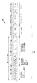
図5は、本発明の特徴を組み込んだ例示的4×4のMIMOシステム用の例示的プリアンブルの形式および出力設計を示す。図5に示すように、全4つの送信機TX1〜TX4は、区間505中の短いトレーニング系列STSの送信に対して同時にアクティブとなる。図5に示す記号550に基づいて、各送信機TX1〜TX4は、例示的実施形態では+14dBmの標準出力レベルでSTSを送信している。STS区間505の開始では、送信/受信スイッチ490用の制御信号、TXONが作動されて、すべての送信ブランチTX1〜TX4を送信モードにする。さらに、2マイクロ秒の遅延により、出力増幅器がランプアップされて、デジタル−アナログ変換器420がSTSシンボルの生成を開始する。
FIG. 5 illustrates an exemplary preamble format and output design for an exemplary 4 × 4 MIMO system incorporating features of the present invention. As shown in FIG. 5, all four transmitters TX <b> 1 to TX <b> 4 are simultaneously active for transmission of the short training sequence STS in the
その後、LTSが、上述のようにアンテナ毎の方法で各送信機によって送信される。したがって、第1のアクティブの送信機TX1は、区間510の間にLTSを送信し、その他の送信機TX2〜TX4はサイレントである。アクティブの送信機TX1は、本発明に従って20dBmだけ出力レベルを高めてLTSを送信する。その間、サイレントの送信機TX2〜TX4は、サイレントモードの間−10dBm以下の出力レベルで送信する。区間510の間は、送信/受信スイッチ490のそれぞれの制御信号、TXONが、第1の送信ブランチTX1を送信モードに、残りの送信ブランチTX2〜TX4を受信モードにするよう制御される。
The LTS is then transmitted by each transmitter in a per antenna manner as described above. Thus, the first active transmitter TX1 transmits an LTS during
第2のLTS区間515の間は、第2の送信機TX2がアクティブであって、20dBmの高められた出力レベルでLTSを送信し、その他の送信機TX1、TX3、TX4はサイレントであって、サイレントモード中出力レベルは−10dBm以下である。第3のLTS区間520の間は、第3の送信機TX3がアクティブであって、20dBmの高められた出力レベルでLTSを送信し、その他の送信機TX1、TX2、TX4はサイレントであって、サイレントモード中出力レベルは−10dBm以下である。第4のLTS区間525の間は、第4の送信機TX4がアクティブであって、20dBmの高められた出力レベルでLTSを送信し、その他の送信機TX1、TX2、TX3はサイレントであって、サイレントモード中出力レベルは−10dBm以下である。
During the
最終的に、MIMOプリアンブルが完成した後、すべての送信機TX1〜TX4は、区間530の間に適切なバックオフで(すなわち標準出力レベルの+14dBmを使用して)データ・シンボルを送信する。
Finally, after the MIMO preamble is complete, all transmitters TX1-TX4 transmit data symbols with appropriate backoff (ie, using a standard output level of +14 dBm) during
本発明の例示的実施形態について、デジタル論理ブロックに関して説明したが、当業者には明らかであるように、様々な機能は、ソフトウェアプログラムの処理ステップとしてデジタル領域に、回路素子もしくは状態機械によってハードウェアに、またはソフトウェアおよびハードウェアの両方の組合せに実装されることが可能である。このようなソフトウェアは、例えばデジタル信号処理装置、マイクロコントローラ、または汎用コンピュータで使用されることが可能である。このようなハードウェアおよびソフトウェアは、集積回路内に実装された回路の中に組み入れられることが可能である。 Although the exemplary embodiments of the present invention have been described with reference to digital logic blocks, it will be apparent to those skilled in the art that various functions are implemented in the digital domain as circuit processing steps in the hardware by circuit elements or state machines. Or a combination of both software and hardware. Such software can be used, for example, in a digital signal processor, a microcontroller, or a general purpose computer. Such hardware and software can be incorporated into circuitry implemented within an integrated circuit.
したがって、本発明の機能は、これらの方法を実行する方法および装置の形態で組み込まれることが可能である。本発明の1つまたは複数の態様は、プログラムコードの形態で取り入れることができ、例えば記憶媒体に格納される、機械によってロードされるおよび/または実行される、あるいはいくつかの伝送媒体で送信され、プログラムコードがコンピュータなどの機械にロードされて実行されるとき、この機械が本発明を実行する装置になる。汎用プロセッサに実装される場合は、プログラムコードのセグメントがプロセッサと結合し、特定の論理回路に同じように動作する装置を提供する。 Accordingly, the functionality of the present invention can be incorporated in the form of methods and apparatus for performing these methods. One or more aspects of the present invention may be incorporated in the form of program code, for example stored in a storage medium, loaded and / or executed by a machine, or transmitted over several transmission media. When the program code is loaded and executed on a machine such as a computer, this machine becomes an apparatus for executing the present invention. When implemented on a general-purpose processor, the program code segments combine with the processor to provide a device that operates analogously to specific logic circuits.
本明細書に示して説明した実施形態および変形物は、単に本発明の原理を例示するものであり、本発明の範囲および趣旨を逸脱することなく当業者によって様々な変更が行われることが可能であると理解されたい。 The embodiments and variations shown and described herein are merely illustrative of the principles of the invention and various modifications can be made by those skilled in the art without departing from the scope and spirit of the invention. I want to be understood.
Claims (10)
所与の時間に前記送信アンテナ・ブランチの1つのみがアクティブであるようにして、長いトレーニング系列を送信アンテナ・ブランチのそれぞれで送信するステップと、
前記アクティブの送信アンテナ・ブランチを前記所与の時間の間送信モードに設定するステップと、
前記非アクティブの送信アンテナ・ブランチの1つまたは複数を前記所与の時間の間受信モードに設定するステップと
を含む方法。 A method for training per antenna in a multi-antenna communication system having a plurality of transmit antenna branches, comprising:
Transmitting a long training sequence in each of the transmit antenna branches such that only one of the transmit antenna branches is active at a given time;
Setting the active transmit antenna branch to transmit mode for the given time;
Setting one or more of the inactive transmit antenna branches to a receive mode for the given time.
前記複数の送信アンテナ・ブランチのそれぞれと関連する送信/受信スイッチであって、前記アクティブの送信アンテナ・ブランチが、前記所与の時間の間送信モードに設定され、前記非アクティブの送信アンテナ・ブランチの1つまたは複数が、前記所与の時間の間受信モードに設定されるようにする送信/受信スイッチと
を含む、複数アンテナの通信システムの送信機。 A plurality of transmit antenna branches for transmitting a long training sequence such that only one of the transmit antenna branches is active at a given time;
A transmit / receive switch associated with each of the plurality of transmit antenna branches, wherein the active transmit antenna branch is set to transmit mode for the given time and the inactive transmit antenna branch; A transmitter / receiver switch that causes one or more of the to be set to receive mode for the given time.
メモリと、
前記メモリに結合された少なくとも1つの処理装置であって、
所与の時間に複数の送信アンテナ・ブランチの1つのみがアクティブであるようにして、前記複数の送信アンテナ・ブランチで送信する長いトレーニング系列を生成し、
前記複数の送信アンテナ・ブランチのそれぞれと関連し、前記アクティブの送信アンテナ・ブランチが、前記所与の時間の間送信モードに設定され、前記非アクティブの送信アンテナ・ブランチの1つまたは複数が、前記所与の時間の間受信モードに設定されるようにする送信/受信スイッチの制御信号を生成するように動作する少なくとも1つの処理装置と
を含む、デジタル信号処理装置。 A digital signal processing device for a communication system with multiple antennas,
Memory,
At least one processing unit coupled to the memory, comprising:
Generating a long training sequence to transmit on the plurality of transmit antenna branches such that only one of the plurality of transmit antenna branches is active at a given time;
Associated with each of the plurality of transmit antenna branches, the active transmit antenna branch is set to transmit mode for the given time, and one or more of the inactive transmit antenna branches are A digital signal processing device comprising: at least one processing device operable to generate a control signal for a transmit / receive switch that causes the receive mode to be set for the given time.
Applications Claiming Priority (3)
| Application Number | Priority Date | Filing Date | Title |
|---|---|---|---|
| US11/388,330 US8694030B2 (en) | 2006-03-24 | 2006-03-24 | Method and apparatus for improved antenna isolation for per-antenna training using transmit/receive switch |
| US11/388,330 | 2006-03-24 | ||
| PCT/US2006/029557 WO2007111631A1 (en) | 2006-03-24 | 2006-07-31 | Method and apparatus for improved antenna isolation for per-antenna training using transmit/receive switch |
Publications (3)
| Publication Number | Publication Date |
|---|---|
| JP2009530965A JP2009530965A (en) | 2009-08-27 |
| JP2009530965A5 JP2009530965A5 (en) | 2009-10-08 |
| JP5330223B2 true JP5330223B2 (en) | 2013-10-30 |
Family
ID=37561080
Family Applications (1)
| Application Number | Title | Priority Date | Filing Date |
|---|---|---|---|
| JP2009501401A Expired - Fee Related JP5330223B2 (en) | 2006-03-24 | 2006-07-31 | Method and apparatus for improving antenna isolation for per-antenna training using a transmit / receive switch |
Country Status (6)
| Country | Link |
|---|---|
| US (1) | US8694030B2 (en) |
| EP (1) | EP2002559B1 (en) |
| JP (1) | JP5330223B2 (en) |
| KR (1) | KR101280205B1 (en) |
| DE (1) | DE602006017268D1 (en) |
| WO (1) | WO2007111631A1 (en) |
Families Citing this family (13)
| Publication number | Priority date | Publication date | Assignee | Title |
|---|---|---|---|---|
| EP1784930B1 (en) | 2004-05-04 | 2016-03-23 | Sony Corporation | Training sequence allocations for MIMO transmissions |
| KR20060098111A (en) * | 2005-03-09 | 2006-09-18 | 삼성전자주식회사 | Portable device |
| US7596112B2 (en) * | 2005-03-22 | 2009-09-29 | Interdigital Technology Corporation | Method and apparatus for rate compatible dirty paper coding |
| US7856250B2 (en) * | 2006-03-28 | 2010-12-21 | Samsung Electronics Co., Ltd. | Apparatus and method for managing SOHO BTS interference using antenna beam coverage based on pilot strength measurement messages |
| US8854252B2 (en) * | 2008-09-12 | 2014-10-07 | Propagation Research Associates, Inc. | Multi-mode, multi-static interferometer utilizing pseudo orthogonal codes |
| US8718169B2 (en) * | 2010-06-15 | 2014-05-06 | Qualcomm Incorporated | Using a field format on a communication device |
| KR20120018266A (en) | 2010-08-20 | 2012-03-02 | 삼성전자주식회사 | Method and apparatus for controlling power amplifier consumption power of base station in wireless communication system using orthogonal frequency division multiple access |
| TWI452861B (en) * | 2010-10-08 | 2014-09-11 | Realtek Semiconductor Corp | Antenna diversity apparatus and antenna diversity method |
| US10571224B2 (en) | 2015-05-04 | 2020-02-25 | Propagation Research Associates, Inc. | Systems, methods and computer-readable media for improving platform guidance or navigation using uniquely coded signals |
| JP6480286B2 (en) * | 2015-08-07 | 2019-03-06 | 日本電信電話株式会社 | Wireless communication system and wireless communication method |
| US9736794B1 (en) * | 2016-03-30 | 2017-08-15 | T-Mobile Usa, Inc. | Dynamic antenna reference signal transmission |
| US10356719B2 (en) | 2016-06-24 | 2019-07-16 | Microsoft Technology Licensing, Llc | Skip-correlation based symmetric carrier sensing with multiple power levels |
| US11018705B1 (en) | 2020-07-17 | 2021-05-25 | Propagation Research Associates, Inc. | Interference mitigation, target detection, location and measurement using separable waveforms transmitted from spatially separated antennas |
Family Cites Families (12)
| Publication number | Priority date | Publication date | Assignee | Title |
|---|---|---|---|---|
| JP2002009679A (en) | 2000-06-26 | 2002-01-11 | Matsushita Electric Ind Co Ltd | Wireless terminal |
| US6711124B2 (en) | 2001-05-25 | 2004-03-23 | Ericsson Inc. | Time interval based channel estimation with transmit diversity |
| US6987950B2 (en) * | 2002-07-25 | 2006-01-17 | Qualcomm, Incorporated | Radio with duplexer bypass capability |
| US7352688B1 (en) * | 2002-12-31 | 2008-04-01 | Cisco Technology, Inc. | High data rate wireless bridging |
| US7916803B2 (en) | 2003-04-10 | 2011-03-29 | Qualcomm Incorporated | Modified preamble structure for IEEE 802.11a extensions to allow for coexistence and interoperability between 802.11a devices and higher data rate, MIMO or otherwise extended devices |
| WO2005006701A1 (en) | 2003-06-30 | 2005-01-20 | Agere Systems Inc. | Method and apparatus for communicating symbols in a multiple input multiple output communication system using interleaved subcarriers across a plurality of antennas |
| US7352718B1 (en) * | 2003-07-22 | 2008-04-01 | Cisco Technology, Inc. | Spatial division multiple access for wireless networks |
| US6917311B2 (en) | 2003-08-11 | 2005-07-12 | Texas Instruments Incorporated | Orthogonal preamble encoder, method of encoding orthogonal preambles and multiple-input, multiple-output communication system employing the same |
| US20050169397A1 (en) * | 2004-01-29 | 2005-08-04 | Texas Instruments Incorporated | Scalable data reception gain control for a multiple-input, multiple-output (MIMO) communications system |
| US7643848B2 (en) * | 2004-04-13 | 2010-01-05 | Qualcomm, Incorporated | Multi-antenna transceiver system |
| US8619907B2 (en) | 2004-06-10 | 2013-12-31 | Agere Systems, LLC | Method and apparatus for preamble training in a multiple antenna communication system |
| KR100719339B1 (en) * | 2004-08-13 | 2007-05-17 | 삼성전자주식회사 | Frame transmitting and receiving method by channel estimation in multiple input multiple output wireless communication system |
-
2006
- 2006-03-24 US US11/388,330 patent/US8694030B2/en active Active
- 2006-07-31 JP JP2009501401A patent/JP5330223B2/en not_active Expired - Fee Related
- 2006-07-31 WO PCT/US2006/029557 patent/WO2007111631A1/en active Application Filing
- 2006-07-31 EP EP06788875A patent/EP2002559B1/en not_active Expired - Fee Related
- 2006-07-31 KR KR1020087023211A patent/KR101280205B1/en not_active IP Right Cessation
- 2006-07-31 DE DE602006017268T patent/DE602006017268D1/en active Active
Also Published As
| Publication number | Publication date |
|---|---|
| US8694030B2 (en) | 2014-04-08 |
| DE602006017268D1 (en) | 2010-11-11 |
| US20070224947A1 (en) | 2007-09-27 |
| EP2002559A1 (en) | 2008-12-17 |
| KR101280205B1 (en) | 2013-06-28 |
| KR20080106447A (en) | 2008-12-05 |
| WO2007111631A1 (en) | 2007-10-04 |
| JP2009530965A (en) | 2009-08-27 |
| EP2002559B1 (en) | 2010-09-29 |
Similar Documents
| Publication | Publication Date | Title |
|---|---|---|
| JP5330223B2 (en) | Method and apparatus for improving antenna isolation for per-antenna training using a transmit / receive switch | |
| JP5313506B2 (en) | Method and apparatus for preamble training with shortened long training field in multi-antenna communication system | |
| JP5345317B2 (en) | Method and apparatus for preamble training in a multi-antenna communication system | |
| US8351882B2 (en) | Amplifying a transmit signal using a fractional power amplifier | |
| JP4573834B2 (en) | Method and apparatus for backward compatible communication in a multiple antenna communication system using time orthogonal symbols | |
| US8498362B2 (en) | Channel sounding and estimation strategies for antenna selection in MIMO systems | |
| US9749022B2 (en) | Channel sounding and estimation strategies in MIMO systems | |
| JP4663734B2 (en) | System and method capable of implicit feedback for a device comprising unequal number of transmitter and receiver chains in a wireless local area network | |
| JP2000278243A (en) | Diversity receiver | |
| JP2007525098A (en) | Method and apparatus for communicating codes in a multiple-input multiple-output communication system using interleaved subcarriers across multiple antennas | |
| KR101140487B1 (en) | Method and apparatus for improved antenna isolation for per-antenna training using variable scaling | |
| US20110263213A1 (en) | Amplifying a transmit signal using a fractional power amplifier | |
| JP3613266B2 (en) | Diversity receiver |
Legal Events
| Date | Code | Title | Description |
|---|---|---|---|
| A521 | Request for written amendment filed |
Free format text: JAPANESE INTERMEDIATE CODE: A523 Effective date: 20090729 |
|
| A621 | Written request for application examination |
Free format text: JAPANESE INTERMEDIATE CODE: A621 Effective date: 20090729 |
|
| A521 | Request for written amendment filed |
Free format text: JAPANESE INTERMEDIATE CODE: A523 Effective date: 20100722 |
|
| A977 | Report on retrieval |
Free format text: JAPANESE INTERMEDIATE CODE: A971007 Effective date: 20111227 |
|
| A131 | Notification of reasons for refusal |
Free format text: JAPANESE INTERMEDIATE CODE: A131 Effective date: 20120118 |
|
| A02 | Decision of refusal |
Free format text: JAPANESE INTERMEDIATE CODE: A02 Effective date: 20120620 |
|
| A61 | First payment of annual fees (during grant procedure) |
Free format text: JAPANESE INTERMEDIATE CODE: A61 Effective date: 20130725 |
|
| R150 | Certificate of patent or registration of utility model |
Ref document number: 5330223 Country of ref document: JP Free format text: JAPANESE INTERMEDIATE CODE: R150 Free format text: JAPANESE INTERMEDIATE CODE: R150 |
|
| S111 | Request for change of ownership or part of ownership |
Free format text: JAPANESE INTERMEDIATE CODE: R313113 |
|
| S533 | Written request for registration of change of name |
Free format text: JAPANESE INTERMEDIATE CODE: R313533 |
|
| R350 | Written notification of registration of transfer |
Free format text: JAPANESE INTERMEDIATE CODE: R350 |
|
| R371 | Transfer withdrawn |
Free format text: JAPANESE INTERMEDIATE CODE: R371 |
|
| S111 | Request for change of ownership or part of ownership |
Free format text: JAPANESE INTERMEDIATE CODE: R313113 |
|
| R371 | Transfer withdrawn |
Free format text: JAPANESE INTERMEDIATE CODE: R371 |
|
| S111 | Request for change of ownership or part of ownership |
Free format text: JAPANESE INTERMEDIATE CODE: R313113 |
|
| R350 | Written notification of registration of transfer |
Free format text: JAPANESE INTERMEDIATE CODE: R350 |
|
| R250 | Receipt of annual fees |
Free format text: JAPANESE INTERMEDIATE CODE: R250 |
|
| R250 | Receipt of annual fees |
Free format text: JAPANESE INTERMEDIATE CODE: R250 |
|
| R250 | Receipt of annual fees |
Free format text: JAPANESE INTERMEDIATE CODE: R250 |
|
| S111 | Request for change of ownership or part of ownership |
Free format text: JAPANESE INTERMEDIATE CODE: R313111 |
|
| R350 | Written notification of registration of transfer |
Free format text: JAPANESE INTERMEDIATE CODE: R350 |
|
| R250 | Receipt of annual fees |
Free format text: JAPANESE INTERMEDIATE CODE: R250 |
|
| LAPS | Cancellation because of no payment of annual fees |