JP5329770B2 - Image converter - Google Patents
Image converter Download PDFInfo
- Publication number
- JP5329770B2 JP5329770B2 JP2007122996A JP2007122996A JP5329770B2 JP 5329770 B2 JP5329770 B2 JP 5329770B2 JP 2007122996 A JP2007122996 A JP 2007122996A JP 2007122996 A JP2007122996 A JP 2007122996A JP 5329770 B2 JP5329770 B2 JP 5329770B2
- Authority
- JP
- Japan
- Prior art keywords
- motion vector
- video signal
- frame
- rate
- unit
- Prior art date
- Legal status (The legal status is an assumption and is not a legal conclusion. Google has not performed a legal analysis and makes no representation as to the accuracy of the status listed.)
- Active
Links
Images
Classifications
-
- H—ELECTRICITY
- H04—ELECTRIC COMMUNICATION TECHNIQUE
- H04N—PICTORIAL COMMUNICATION, e.g. TELEVISION
- H04N7/00—Television systems
- H04N7/01—Conversion of standards, e.g. involving analogue television standards or digital television standards processed at pixel level
- H04N7/0135—Conversion of standards, e.g. involving analogue television standards or digital television standards processed at pixel level involving interpolation processes
- H04N7/014—Conversion of standards, e.g. involving analogue television standards or digital television standards processed at pixel level involving interpolation processes involving the use of motion vectors
-
- H—ELECTRICITY
- H04—ELECTRIC COMMUNICATION TECHNIQUE
- H04N—PICTORIAL COMMUNICATION, e.g. TELEVISION
- H04N19/00—Methods or arrangements for coding, decoding, compressing or decompressing digital video signals
- H04N19/10—Methods or arrangements for coding, decoding, compressing or decompressing digital video signals using adaptive coding
- H04N19/102—Methods or arrangements for coding, decoding, compressing or decompressing digital video signals using adaptive coding characterised by the element, parameter or selection affected or controlled by the adaptive coding
- H04N19/132—Sampling, masking or truncation of coding units, e.g. adaptive resampling, frame skipping, frame interpolation or high-frequency transform coefficient masking
-
- H—ELECTRICITY
- H04—ELECTRIC COMMUNICATION TECHNIQUE
- H04N—PICTORIAL COMMUNICATION, e.g. TELEVISION
- H04N19/00—Methods or arrangements for coding, decoding, compressing or decompressing digital video signals
- H04N19/50—Methods or arrangements for coding, decoding, compressing or decompressing digital video signals using predictive coding
- H04N19/503—Methods or arrangements for coding, decoding, compressing or decompressing digital video signals using predictive coding involving temporal prediction
- H04N19/51—Motion estimation or motion compensation
- H04N19/513—Processing of motion vectors
-
- H—ELECTRICITY
- H04—ELECTRIC COMMUNICATION TECHNIQUE
- H04N—PICTORIAL COMMUNICATION, e.g. TELEVISION
- H04N19/00—Methods or arrangements for coding, decoding, compressing or decompressing digital video signals
- H04N19/50—Methods or arrangements for coding, decoding, compressing or decompressing digital video signals using predictive coding
- H04N19/587—Methods or arrangements for coding, decoding, compressing or decompressing digital video signals using predictive coding involving temporal sub-sampling or interpolation, e.g. decimation or subsequent interpolation of pictures in a video sequence
-
- H—ELECTRICITY
- H04—ELECTRIC COMMUNICATION TECHNIQUE
- H04N—PICTORIAL COMMUNICATION, e.g. TELEVISION
- H04N7/00—Television systems
- H04N7/01—Conversion of standards, e.g. involving analogue television standards or digital television standards processed at pixel level
- H04N7/0127—Conversion of standards, e.g. involving analogue television standards or digital television standards processed at pixel level by changing the field or frame frequency of the incoming video signal, e.g. frame rate converter
Landscapes
- Engineering & Computer Science (AREA)
- Multimedia (AREA)
- Signal Processing (AREA)
- Television Systems (AREA)
Abstract
Description
本発明は、入力した第1のフレームレートを持つ映像信号を、第2のフレームレートを持つ映像信号にレート変換することにより出力するフレームレート変換部を備える画像変換装置に関する。 The present invention relates to an image conversion apparatus including a frame rate conversion unit that outputs an input video signal having a first frame rate by performing rate conversion to a video signal having a second frame rate.
従来、動画像情報の変換符号化装置において、可変に分割されたブロックを採用した第1の動画像符号化方式から、可変に分割されたブロックを採用していない第2の動画像符号化方式へ、品質を落とさずに高速で且つ発生符号量の抑制が可能な再符号化を行えるようにすることを目的とした提案がなされている。 2. Description of the Related Art Conventionally, in a transform coding apparatus for moving image information, a second moving image coding method that does not employ a variable divided block is changed from a first moving image coding method that employs a variable divided block. On the other hand, proposals have been made for the purpose of enabling re-encoding capable of suppressing the generated code amount at high speed without degrading quality.
該提案に係る動画像情報変換符号化装置では、動画像符号化方式を変換する前の動きベクトルの相関値ρが閾値ρ1以上であれば、相関が大きく、動画像符号化方式を変換する前に算出された2本の動きベクトルの平均値Vmを変換した後の動きベクトルとして再利用する。相関値ρが閾値ρ2とρ1との間の値をとる場合は、平均Vmを動きベクトルとして用いると誤差が大きくなると判断し、変換前の2本の動きベクトルの平均Vmの点を中心として変換後の動きベクトルを再計算する。相関値ρが閾値2より小さい場合は、相関が極めて小さいので、通常の探索範囲で変換後の動きベクトルの再計算を行う(特許文献1参照)。
In video information transform coding apparatus according to this proposal, the correlation value of the previous motion vectors for converting the moving picture coding method [rho is equal to the threshold value [rho 1 or more, the correlation is large, it converts the moving picture coding method The average value V m of the two motion vectors calculated before is reused as a motion vector after conversion. When the correlation value ρ takes a value between the threshold values ρ 2 and ρ 1 , it is determined that the error increases when the average V m is used as a motion vector, and the point of the average V m of the two motion vectors before conversion is determined. The motion vector after conversion is recalculated centering on. When the correlation value ρ is smaller than the
ここで、動きベクトルとは、先行する(過去に表示された)画像と、現在表示中の画像との間で、一定の探索範囲内で実行される(動きベクトル決定のための)マッチングにおいて、最もマッチングが取れた画素同士を結ぶベクトルのことを指す。換言すれば、動きベクトルとは、動画のデータの表現方法として、基準となるフレーム(動画の或る瞬間に相当する画像)と、基準となるフレームからの動きとをベクトルとして表現する手法であり、次元としては位置(通常は画素数で表現する)であって、移動量を指す。 Here, a motion vector is a matching (for determining a motion vector) executed within a certain search range between a preceding image (displayed in the past) and an image currently displayed. It refers to the vector that connects the most matched pixels. In other words, the motion vector is a method of expressing a reference frame (an image corresponding to a certain moment of the moving image) and a motion from the reference frame as a vector as a method of expressing moving image data. The dimension is a position (usually expressed by the number of pixels) and indicates a movement amount.
ところで、上記従来の技術では、上述したように、動画像符号化方式を変換する前の動きベクトルの相関値が閾値以上であれば、上記動画像符号化方式を変換する前に算出された2本の動きベクトルの平均値を、変換した後の動きベクトルとして再利用する。これは、入力映像信号の動きベクトルを、出力映像信号の動きベクトルとしてそのまま使用することを意味している。 By the way, in the above conventional technique, as described above, if the correlation value of the motion vector before converting the moving image coding method is equal to or greater than the threshold value, 2 calculated before converting the moving image coding method. The average value of the motion vectors of the book is reused as the motion vector after conversion. This means that the motion vector of the input video signal is used as it is as the motion vector of the output video signal.
一方、上記相関値が1つの閾値と他の閾値との間の値をとる場合や、相関値が他方の閾値より小さい場合には、通常の探索範囲で変換後の動きベクトルの再計算を行う。これは、出力映像信号から、その動きベクトルを再探索することを意味している。 On the other hand, when the correlation value takes a value between one threshold value and another threshold value, or when the correlation value is smaller than the other threshold value, the motion vector after conversion is recalculated in the normal search range. . This means that the motion vector is re-searched from the output video signal.
しかし、入力映像信号の動きベクトルを、出力映像信号の動きベクトルとしてそのまま使用すると、入力映像信号のフレームレートと、出力映像信号のフレームレートとが相違する場合に、出力映像信号と上記動きベクトルとの間の相関関係が低いために、出力映像信号に大きな画質劣化が生じるのを避けられないという問題がある。また、出力映像信号から、その動きベクトルを再探索する方法を採用すると、入力映像信号、及び出力映像信号の双方に対し、夫々動きベクトルの探索を実行しなければならないから、装置の回路規模が増大するのみならず、装置の処理負荷も増大するという問題がある。 However, if the motion vector of the input video signal is used as it is as the motion vector of the output video signal, if the frame rate of the input video signal is different from the frame rate of the output video signal, the output video signal and the motion vector Since there is a low correlation between the two, there is a problem that it is inevitable that a large deterioration in image quality occurs in the output video signal. If a method for re-searching the motion vector from the output video signal is employed, the motion vector search must be executed for both the input video signal and the output video signal, so that the circuit scale of the apparatus is increased. In addition to the increase, there is a problem that the processing load of the apparatus also increases.
従って本発明の目的は、入力映像信号と出力映像信号とで、双方のフレームレートが異なる場合にも、装置の回路規模や処理負荷を増大させることなく、且つ、出力映像信号の画質を劣化させることなく、出力映像信号の画像補正を行える画像変換技術を提供することにある。 Accordingly, an object of the present invention is to reduce the image quality of an output video signal without increasing the circuit scale and processing load of the apparatus even when the input video signal and the output video signal have different frame rates. An object of the present invention is to provide an image conversion technique that can correct an image of an output video signal.
本発明の第1の観点に従う画像変換装置は、入力した第1のフレームレートを持つ映像信号を、第2のフレームレートを持つ映像信号にレート変換することにより出力するフレームレート変換部と、上記第1のフレームレートを持つ映像信号から、動きベクトルを検出する動きベクトル検出部と、上記動きベクトル検出部により検出された動きベクトルに所定の演算処理を施すことによって、上記動きベクトルを、上記第2のフレームレートを持つ映像信号のフレームレートと同一レートの動きベクトルにレート変換する動きベクトルレート変換部と、上記フレームレート変換部から出力される上記第2のフレームレートを持つ映像信号を、上記動きベクトルレート変換部によりレート変換された動きベクトルを利用して補正する映像信号補正部と、を備える。 An image conversion apparatus according to a first aspect of the present invention includes a frame rate conversion unit that outputs an input video signal having a first frame rate by performing rate conversion to a video signal having a second frame rate; A motion vector detection unit that detects a motion vector from a video signal having a first frame rate, and a predetermined arithmetic process performed on the motion vector detected by the motion vector detection unit, thereby converting the motion vector into the first vector. A motion vector rate conversion unit that performs rate conversion to a motion vector having the same rate as the frame rate of a video signal having a frame rate of 2, and the video signal having the second frame rate output from the frame rate conversion unit, Video signal compensation corrected using the motion vector rate-converted by the motion vector rate converter It comprises a part, a.
本発明の第1の観点に係る好適な実施形態では、上記動きベクトル検出部が、上記第1のフレームレートを持つ映像信号における連続する前後2つのフレームの間で、位置が同一である画素同士の間を通るベクトルを上記第1のフレームレートを持つ映像信号の動きベクトルとして検出する。 In a preferred embodiment according to the first aspect of the present invention, the motion vector detection unit includes pixels having the same position between two consecutive frames in the video signal having the first frame rate. Are detected as motion vectors of the video signal having the first frame rate.
上記とは別の実施形態では、上記動きベクトル検出部による上記動きベクトルの検出動作が、上記各々のフレームを構成する全ての画素について行われる。 In an embodiment different from the above, the motion vector detection operation by the motion vector detection unit is performed for all the pixels constituting each frame.
また、上記とは別の実施形態では、上記第1のフレームレートを持つ映像信号における連続する前後2つのフレームの一方が、1フレーム分遅延されたフレームであり、他方が1フレーム分遅延されていないフレームであって、上記両フレームが同時参照されることにより上記動きベクトルが検出される。 In another embodiment different from the above, one of two consecutive frames in the video signal having the first frame rate is a frame delayed by one frame, and the other is delayed by one frame. The motion vector is detected by referring to both the frames simultaneously.
また、上記とは別の実施形態では、上記動きベクトルレート変換部による上記動きベクトルのレート変換が、上記動きベクトル検出部により上記第1のフレームレートを持つ映像信号から検出された連続する前後2つの動きベクトルを用いて所定の演算処理を行う手順を含む。 In another embodiment, the motion vector rate conversion by the motion vector rate conversion unit may be performed before and after the motion vector rate conversion unit detected by the motion vector detection unit from the video signal having the first frame rate. This includes a procedure for performing predetermined arithmetic processing using two motion vectors.
また、上記とは別の実施形態では、上記動きベクトルレート変換部による上記動きベクトルのレート変換が、上記動きベクトル検出部により上記第1のフレームレートを持つ映像信号から検出された、現時点におけるレート変換の1つ前のレート変換において生成された動きベクトルの複製を用いて所定の演算処理を行う手順を含む。 In another embodiment different from the above, the rate at which the motion vector rate is converted by the motion vector rate converter detected from the video signal having the first frame rate detected by the motion vector detector. This includes a procedure for performing a predetermined calculation process using a copy of the motion vector generated in the rate conversion immediately before the conversion.
また、上記とは別の実施形態では、上記所定の演算処理が、上記動きベクトル検出部により上記第1のフレームレートを持つ映像信号から検出された動きベクトルをレート変換するのに必要な第1又は、第1、第2の係数を用いる演算処理である。 In another embodiment different from the above, the predetermined calculation process may include a first calculation required for rate conversion of a motion vector detected from the video signal having the first frame rate by the motion vector detection unit. Or, it is a calculation process using the first and second coefficients.
また、上記とは別の実施形態では、上記第1、第2の係数が、上記第1のフレームレートを持つ映像信号と、上記第2のフレームレートを持つ映像信号とにより決定される、上記第1のフレームレートを持つ映像信号の動きベクトルの、上記第2のフレームレートを持つ映像信号の動きベクトルへのレート変換の周期に応じて比率が可変される。 In another embodiment, the first and second coefficients are determined by a video signal having the first frame rate and a video signal having the second frame rate. The ratio is varied according to the rate conversion period of the motion vector of the video signal having the first frame rate to the motion vector of the video signal having the second frame rate.
更に、上記とは別の実施形態では、上記動きベクトル検出部によって検出される動きベクトルが、その情報量を所定の手順で間引かれた状態で保存され、上記動きベクトルレート変換部による上記動きベクトルのレート変換時において、所定の手順で元の情報量に復元されるようになっている。 Further, in another embodiment, the motion vector detected by the motion vector detection unit is stored in a state where the information amount is thinned out in a predetermined procedure, and the motion vector rate conversion unit performs the motion At the time of vector rate conversion, the original information amount is restored by a predetermined procedure.
本発明の第2の観点に従うディジタルTV放送受信機は、映像信号を入/出力するための映像信号入/出力部と、画像表示部と、供給された映像信号に、所定の信号処理を施して上記画像表示部に出力する映像信号処理部と、上記映像信号入/出力部を通じて入力した映像信号を録画すると共に、録画した映像信号を再生して上記映像信号入/出力部、又は上記映像信号処理部に出力する録画/再生部と、を備え、上記映像信号処理部が、入力した第1のフレームレートを持つ映像信号を、第2のフレームレートを持つ映像信号にレート変換することにより出力するフレームレート変換部と、上記第1のフレームレートを持つ映像信号から、動きベクトルを検出する動きベクトル検出部と、上記動きベクトル検出部により検出された動きベクトルに所定の演算処理を施すことによって、上記動きベクトルを、上記第2のフレームレートを持つ映像信号のフレームレートと同一レートの動きベクトルにレート変換する動きベクトルレート変換部と、上記フレームレート変換部から出力される上記第2のフレームレートを持つ映像信号を、上記動きベクトルレート変換部によりレート変換された動きベクトルを利用して補正する映像信号補正部と、を含む。 A digital TV broadcast receiver according to a second aspect of the present invention performs predetermined signal processing on a video signal input / output unit for inputting / outputting a video signal, an image display unit, and the supplied video signal. The video signal processing unit for outputting to the image display unit and the video signal input through the video signal input / output unit are recorded, and the recorded video signal is reproduced to reproduce the video signal input / output unit or the video. A video recording / playback unit for outputting to the signal processing unit, and the video signal processing unit rate-converts the input video signal having the first frame rate into a video signal having the second frame rate. An output frame rate conversion unit; a motion vector detection unit that detects a motion vector from the video signal having the first frame rate; and a motion vector detected by the motion vector detection unit. A motion vector rate conversion unit that converts the motion vector into a motion vector having the same rate as the frame rate of the video signal having the second frame rate by performing predetermined arithmetic processing on the frame; and the frame rate conversion A video signal correcting unit that corrects the video signal having the second frame rate output from the unit using the motion vector rate-converted by the motion vector rate converting unit.
本発明の第3の観点に従う画像変換方法は、入力した第1のフレームレートを持つ映像信号を、第2のフレームレートを持つ映像信号にレート変換することにより出力する第1のステップと、上記第1のフレームレートを持つ映像信号から、動きベクトルを検出する第2のステップと、上記第2のステップにおいて検出された動きベクトルに所定の演算処理を施すことによって、上記動きベクトルを、上記第2のフレームレートを持つ映像信号のフレームレートと同一レートの動きベクトルにレート変換する第3のステップと、上記第1のステップにおいて出力される上記第2のフレームレートを持つ映像信号を、上記第3のステップにおいてレート変換された動きベクトルを利用して補正する第4のステップと、を備える。 An image conversion method according to a third aspect of the present invention includes a first step of outputting an input video signal having a first frame rate by converting the rate to a video signal having a second frame rate; A second step of detecting a motion vector from a video signal having a first frame rate, and applying a predetermined arithmetic process to the motion vector detected in the second step, A third step of rate conversion to a motion vector having the same rate as the frame rate of the video signal having a frame rate of 2, and the video signal having the second frame rate output in the first step And a fourth step of correcting using the motion vector that has been rate-converted in the third step.
本発明によれば、入力映像信号と出力映像信号とで、双方のフレームレートが異なる場合にも、装置の回路規模や処理負荷を増大させることなく、且つ、出力映像信号の画質を劣化させることなく、出力映像信号の画像補正を行える画像変換技術を提供することができる。 According to the present invention, even when the input video signal and the output video signal have different frame rates, the image quality of the output video signal is deteriorated without increasing the circuit scale and processing load of the apparatus. In addition, it is possible to provide an image conversion technique that can perform image correction of an output video signal.
以下、本発明の実施の形態を、図面により詳細に説明する。 Hereinafter, embodiments of the present invention will be described in detail with reference to the drawings.
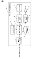
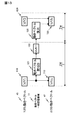
図1は、本発明の一実施形態に係るディジタルテレビジョン(TV)受信機の全体構成を示す機能ブロック図である。 FIG. 1 is a functional block diagram showing the overall configuration of a digital television (TV) receiver according to an embodiment of the present invention.
図1に示すように、本発明の一実施形態に係るディジタルTV受信機100は、動画擬似輪郭補正機能を備えたプラズマ方式のディジタルTV受信機である。ディジタルTV受信機100は、映像入/出力部1と、ユーザインタフェース(I/F)部3と、録画/再生部5と、映像コンテンツ蓄積部7と、映像信号処理部9と、プラズマパネルディスプレイ11と、音声信号処理部13と、スピーカ15と、を備える。
As shown in FIG. 1, a
映像入/出力部1は、ディジタルTV受信機100が、放送局(図示しない)から送信されるディジタルTV放送電波の受信や、インターネット等の通信ネットワーク上に存在するディジタル映像コンテンツのディジタルTV受信機100へのダウンロードに際して必要な処理動作を行う。映像入/出力部1は、また、ディジタルTV受信機100が録画した映像コンテンツを、(例えばインターネット等の通信ネットワークを通じて)外部のAV機器類(図示しない)等に出力するに際して必要な処理動作をも実行する。
The video input /
ユーザI/F部3は、ユーザが、例えばディジタルTV受信機100に備えられるリモートコントローラ(リモコン)(図示しない)を操作することにより、リモコン(図示しない)からディジタルTV受信機100に送信される各種の指令を受付ける。
The user I /
録画/再生部5は、ユーザI/F部3、及びリモコン(図示しない)を通じてユーザから与えられる映像コンテンツの録画指令に従い、映像入/出力部1から出力される映像コンテンツを録画して、該録画した映像コンテンツを、映像コンテンツ蓄積部7に出力する。録画/再生部5は、また、ユーザI/F部3、及びリモコン(図示しない)を通じてユーザから与えられる映像コンテンツ再生指令に従い、映像コンテンツ蓄積部7に蓄積されている映像コンテンツを読み出して再生する。そして、再生した映像信号については、映像信号処理部9に、再生した音声信号については、音声信号処理部13に、夫々出力する。
The recording /
映像コンテンツ蓄積部7は、録画/再生部5から出力される、録画/再生部5において録画された映像コンテンツを蓄積すると共に、録画/再生部5からの映像コンテンツ読み出し要求に応じて、蓄積している映像コンテンツを録画/再生部5に出力する。
The video
映像信号処理部9は、録画/再生部5から出力される映像信号に所定の手順で加工処理を施して、プラズマパネルディスプレイ11に表示出力する。プラズマパネルディスプレイ11は、映像信号処理部9から出力される映像信号を、可視画像として表示する。
The video
音声信号処理部13は、録画/再生部5から出力される音声信号に所定の手順で加工処理を施して、スピーカ15に出力する。スピーカ15は、音声信号処理部13から出力される音声信号を、可聴音、即ち、音声(音響)として出力する。
The audio
なお、ディジタルTV受信機100としては、上述した動画擬似輪郭補正機能を備えたプラズマ方式のディジタルTV受信機以外にも、出力画像の画質補正機能を備えた液晶方式のディジタルTV受信機を用いることが可能である。
As the
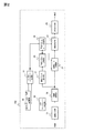
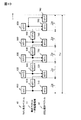
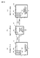
図2は、本発明の一実施形態に係る画像変換装置の全体構成を示す機能ブロック図である。 FIG. 2 is a functional block diagram showing the overall configuration of the image conversion apparatus according to an embodiment of the present invention.
図2に示す画像変換装置200は、図1で示した映像信号処理部9に含まれるもので、映像信号処理部9内に実装されたハードウェアとして具現化することが可能である。また、上記画像変換装置200は、映像信号処理部9を構成するハードウェアに搭載される、該ハードウェアが以下に説明するような画像変換処理を実施するためのソフトウェアとして具現化することも可能である。
The
図2に示すように、本発明の一実施形態に係る画像変換装置200は、画像入力部17と、画像記憶部19と、画像レート変換部21と、画像補正部23と、画像出力部25と、動きベクトル検出部27と、動きベクトル記憶部29と、を備える。画像変換装置200は、上記各部に加えて、更に、動きベクトルレート変換部31と、入力フレームレート検出部33と、出力フレームレート値記憶部35と、入/出力フレームレート制御部37、をも備える。
As shown in FIG. 2, an
画像入力部17は、図1で示した録画/再生部5から出力される映像信号を入力すると共に、該入力した映像信号を構成する全ての画像のフレーム(以下、単に「フレーム」と表記することもある。)を、画像記憶部19、及び入力フレームレート検出部33に夫々出力する。
The
画像記憶部19は、例えば半導体メモリ、或いは磁気ディスク等によって構成されており、画像入力部17から出力される全てのフレームを記憶する。画像記憶部19に記憶された全てのフレームは、所定のタイミングで画像記憶部19から読み出され、画像レート変換部21、及び動きベクトル検出部27に夫々出力される。
The
動きベクトル検出部27は、画像記憶部19から読み出した映像信号の連続する(時間的に見て)前後2つのフレームを参照して、該2つのフレームの間で、位置(平面座標)が同一である画素同士の間を通る動きベクトルを検出する動作を、上記各々のフレームを構成する全ての画素について実行する。動きベクトル検出部27は、上記各々のフレームを構成する全ての画素について検出した動きベクトル(に係わる情報)を、動きベクトル記憶部29に出力する。動きベクトル検出部27が検出した動きベクトル(に係わる情報)の、動きベクトル検出部27からの出力タイミングは、(入力フレームレート検出部33により検出される、)画像入力部17から出力される映像信号の入力フレームレート値のタイミングと同期する。
The motion
動きベクトル記憶部29は、動きベクトル検出部27から出力される、上記動きベクトル(に係わる情報)を、記憶する。動きベクトル記憶部29に記憶された上記動きベクトル(に係わる情報)は、画像レート変換部21によって動きベクトル記憶部29から読み出される。同様に、上記動きベクトル(に係わる情報)は、動きベクトルレート変換部31によっても動きベクトル記憶部29から読み出される。
The motion
入力フレームレート検出部33は、画像入力部17から出力される(映像信号の)各フレーム間の出力タイミングを測定することにより、画像入力部17に入力される映像信号のフレームレート値を求める。入力フレームレート検出部33は、該求めたフレームレート値を、入/出力フレームレート制御部37に出力する。
The input frame
出力フレームレート値記憶部35は、予め設定されている画像変換装置200からの映像信号の出力フレームレート値を記憶する。出力フレームレート値記憶部35は、入/出力フレームレート制御部37からの読み出し要求に応じて、記憶している上記出力フレームレート値を、入/出力フレームレート制御部37に出力する。出力フレームレート値記憶部35には、例えばROMのような半導体記憶素子が採用されている。
The output frame rate
入/出力フレームレート制御部37は、入力フレームレート検出部33から出力される上記映像信号のフレームレート値と、出力フレームレート値記憶部35から出力される出力フレームレート値と、を入力する。そして、入力した(上記映像信号の)入力フレームレート値、及び出力フレームレート値を、画像レート変換部21、及び動きベクトルレート変換部31に夫々出力する。
The input / output frame
画像レート変換部21は、入/出力フレームレート制御部37から出力される上記映像信号の入力フレームレート値、及び画像変換装置200の出力フレームレート値と、動きベクトル記憶部29から出力される上記動きベクトル(に係わる情報)とを入力する。そして、上記入力フレームレート値、出力フレームレート値、及び動きベクトル(に係わる情報)に基づいて決まるフレームレート変換の条件に適合するように、画像記憶部19から出力される映像信号の全てのフレームのレート変換を行う。画像レート変換部21は、フレームのレート変換を行った上記映像信号を、画像補正部23に出力する。
The image
動きベクトルレート変換部31は、入/出力フレームレート制御部37から出力される上記入力フレームレート値、及び出力フレームレート値に基づいて決まるフレームレートの変換条件に適合するように、動きベクトル記憶部29から出力される上記動きベクトル(に係わる情報)のレート変換を行う。動きベクトルレート変換部31は、レート変換を行った後の上記動きベクトル(に係わる情報)を、画像補正部23に出力する。レート変換が行われた後の上記動きベクトル(に係わる情報)の、動きベクトルレート変換部31からの出力タイミングは、入/出力フレームレート制御部37を通じて出力フレームレート値記憶部35から出力される出力フレームレート値のタイミングと同期する。
The motion vector
画像補正部23は、動きベクトルレート変換部31から出力される、上記レート変換された後の動きベクトルに基づいて、画像レート変換部21から出力されるフレームレートの変換が行われた後の上記映像信号に対し、所定のアルゴリズムに従って画像補正処理を施す。ここで、画像補正部23が実施する画像補正処理について説明する。
The
画像補正部23において実施される画像補正処理の一例として、プラズマディスプレイ(以下、「PDP」と略記する。)の動画擬似輪郭補正処理が挙げられる。動画擬似輪郭とは、PDP発光構造と、人の視線がPDP内における画像の移動方向に追従する性質があることとに起因して、或る特定の映像パターンで本来の表示画素値とは異なる輝度階調に人の肉眼(視覚)が錯覚するため、結果的にS/N比の悪化した画像に見えてしまう現象のことである。また、動画擬似輪郭補正処理とは、画像の動きベクトルを参照して、画素の移動方向、即ち、人の視線方向に画素を再構成することで、動画擬似輪郭を低減させる手法のことである。
An example of the image correction process performed in the
画像補正部23は、上記画像補正処理を施した後の映像信号を、画像出力部25に出力する。
The
画像出力部25は、画像補正部23から出力される上記画像補正処理を施した後の映像信号を、上述した出力フレームレート値のタイミングで、画像変換装置200からの映像信号として、図1で示したプラズマパネル11に出力する。
The
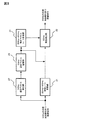
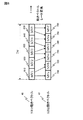
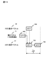
図3は、図2で示した画像変換装置200の要部における、フレーム、及び動きベクトルのレート変換に際しての処理動作を示す機能ブロック図である。
FIG. 3 is a functional block diagram showing processing operations in rate conversion of frames and motion vectors in the main part of the
ところで、日本国内におけるTV放送の映像信号のフレームレートは、60フレーム/秒(以下、画像周波数と称して“60Hz”で表す。)であり、欧州におけるTV放送の映像信号のフレームレートは、50フレーム/秒(以下、画像周波数と称して“50Hz”で表す。)であることが知られている。日本国内において、欧州向けとして製造されるTV受信機の中には、映像品質の向上を目的として、50Hzの画像周波数を持つ映像信号(以下では、「50Hzの映像信号」と略記することもある。)を、TV受信機側で60Hzの画像周波数を持つ映像信号(以下では、「60Hzの映像信号」と略記することもある。)に変換してディスプレイに表示出力する機能を備えるモデルがある。 By the way, the frame rate of video signals of TV broadcasts in Japan is 60 frames / second (hereinafter referred to as “60 Hz” as image frequency), and the frame rate of video signals of TV broadcasts in Europe is 50 frames / second. It is known that it is a frame / second (hereinafter referred to as “50 Hz” as an image frequency). In Japan, some TV receivers manufactured for Europe use video signals with an image frequency of 50 Hz (hereinafter referred to as “50 Hz video signals” for the purpose of improving video quality). .) Is converted to a video signal having an image frequency of 60 Hz on the TV receiver side (hereinafter sometimes abbreviated as “60 Hz video signal”), and there is a model having a function of displaying and displaying on a display. .
以下では、画像変換装置200が、該画像変換装置200に入力される50Hzの映像信号を、60Hzの映像信号に(レート)変換して出力する動作を行うものとして説明する。
In the following description, it is assumed that the
図3において、画像レート変換部21は、(図2で示した)画像記憶部19より50Hzの映像信号を入力し、そのフレームのレート変換を行うことによって60Hzの映像信号として、画像補正部23に出力する。
In FIG. 3, the image
動きベクトル検出部27は、画像記憶部19から読み出した50Hzの映像信号の連続する(時間的に見て)前後2つのフレームを参照して、該2つのフレームの間で、位置が同一である画素同士の間を通る動きベクトルを検出する動作を、上記各々のフレームを構成する全ての画素について実行する。動きベクトル検出部27は、上記各々のフレームを構成する全ての画素について検出した動きベクトルを、50Hzの映像信号の動きベクトル(以下、「50Hzの動きベクトル」と表記することもある。)として、動きベクトル記憶部29に出力する。
The motion
動きベクトル記憶部29は、動きベクトル検出部27から出力される、50Hzの動きベクトルを、記憶する。なお、動きベクトル記憶部29には、後述する動きベクトル一時記憶領域(図10、図11、及び図13において、符号77で示す。)が設定されている。
The motion
動きベクトルレート変換部31は、(図2で示した)入/出力フレームレート制御部37から出力される上記入力フレームレート値(50Hz)、及び出力フレームレート値(60Hz)に基づき、動きベクトル記憶部29から出力される50Hzの動きベクトルを、60Hzの映像信号の動きベクトル(以下、「60Hzの動きベクトル」と表記することもある。)に変換する。動きベクトルレート変換部31は、レート変換を行った後の上記動きベクトル(即ち、60Hzの動きベクトル)を、画像補正部23に出力する。
The motion vector
画像補正部23は、動きベクトルレート変換部31から出力される、60Hzの動きベクトルに基づいて、画像レート変換部21から出力される60Hzの上記映像信号に対し、所定のアルゴリズムに従って画像補正処理を施す。そして、該画像補正処理を施した後の60Hzの上記映像信号を、図2で示した画像出力部25に出力する。
Based on the 60 Hz motion vector output from the motion vector
なお、上述した画像周波数60Hzには、59.94Hzの画像周波数も含まれているものとする。 Note that the image frequency of 60 Hz described above includes an image frequency of 59.94 Hz.
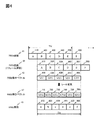
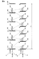
図4は、図2、図3で示した動きベクトル検出部27において行われる動きベクトルの検出動作、及び動きベクトルレート変換部31において行われる動きベクトルの(50Hzから60Hzへの)レート変換動作の概要を示す模式図である。
4 shows the motion vector detection operation performed in the motion
図4において、矢印tは、時間の流れを示す。 In FIG. 4, the arrow t indicates the flow of time.
既述のように、映像信号の動きベクトルは、該映像信号の連続する(時間的に見て)前後2つのフレーム間において、位置が同一である所定の領域内で、位置(平面座標)が同一である画素同士の間を通るベクトルのことを指す。 As described above, the motion vector of the video signal has a position (planar coordinate) within a predetermined region where the position is the same between two consecutive frames (in terms of time) of the video signal. It refers to a vector that passes between identical pixels.
図4においては、50Hzの映像信号における連続する(時間的に見て)前後2つのフレームの、画像レート変換部21、及び動きベクトル検出部27による同時参照が可能なように、1つの50Hzの映像信号が、画像記憶部19から所謂リアルタイムで出力されるのみならず、1フレーム分遅延された状態でも出力される。即ち、図4では、1つの50Hzの映像信号に符号41を、それと同一の50Hzの映像信号であって、1フレーム分遅延されて読み出されたもの(50Hzの映像信号)に符号43を、夫々付して表す。50Hzの映像信号41は、複数個のフレームABCDEFを含み、同様に、50Hzの映像信号43も、上記複数個のフレームと夫々が同一の複数個のフレームABCDEFを含む。説明の便宜のため、50Hzの映像信号41側のフレームにおいては、フレームAに符号410を、フレームBに符号420を、フレームCに符号430を、フレームDに符号440を、フレームEに符号450を、フレームFに符号460を、夫々付す。一方、50Hzの映像信号43のフレームにおいては、フレームAに符号510を、フレームBに符号520を、フレームCに符号530を、フレームDに符号540を、フレームEに符号550を、フレームFに符号560を、夫々付す。
In FIG. 4, one 50 Hz video signal so that the image
ここで、1フレーム分遅延された50Hzの映像信号43とは、動きベクトル検出部27が、50Hzの映像信号41を画像記憶部19から読み出すよりも、1フレーム前に読み出した50Hzの映像信号のことである。
Here, the 50
動きベクトル検出部27は、50Hzの映像信号(41、43)から動きベクトルを検出するために、画像記憶部19から読み出した50Hzの映像信号41を構成する各々のフレームA〜F(410〜460)と、同じく画像記憶部19から時間的に1フレーム分遅延させて読み出した50Hzの映像信号43を構成する各々のフレームA〜F(510〜560)とを、一時的に保持する。
The motion
動きベクトル検出部27は、画像記憶部19から読み出した50Hzの映像信号(41、43)同士の間において、連続する(時間的に見て)前後2つのフレームを参照し、該2つのフレームの間で、所定の領域内での平面座標が同一である画素同士の動きに対応するベクトルを検出する。該ベクトルが、50Hzの動きベクトルである。動きベクトル検出部27による、50Hzの動きベクトルの検出は、図4において符号TWで示す期間、即ち、50Hzの動きベクトル45を、60Hzの動きベクトル47にレート変換するに際してのレート変換処理の対象になる期間(該期間TWは、50Hzの映像信号のフレームレートを、60Hzの映像信号のフレームレートにレート変換するに際してのレート変換処理の対象になる期間でもある。)、行われる。
The motion
即ち、動きベクトル検出部27は、上記読み出した50Hzの映像信号41のフレームB(420)と、1フレーム分遅延させて読み出した上記50Hzの映像信号41よりも1変換周期前の50Hzの映像信号43のフレームA(510)との間において、上記のような態様で、50Hzの動きベクトルMV1(610)を検出する。動きベクトル検出部27は、上記と同様に、上記50Hzの映像信号41のフレームC(430)と、上記50Hzの映像信号43のフレームB(520)との間において、50Hzの動きベクトルMV2(620)を検出する。また、動きベクトル検出部27は、上記と同様に、上記50Hzの映像信号41のフレームD(440)と、上記50Hzの映像信号43のフレームC(530)との間において、50Hzの動きベクトルMV3(630)を検出する。
That is, the motion
また、動きベクトル検出部27は、上記と同様に、上記50Hzの映像信号41のフレームE(450)と、上記50Hzの映像信号43のフレームD(540)との間において、50Hzの動きベクトルMV4(640)を検出する。更に、動きベクトル検出部27は、上記と同様に、上記50Hzの映像信号41のフレームF(460)と、上記50Hzの映像信号43のフレームE(550)との間において、50Hzの動きベクトルMV5(650)を検出する。上記50Hzの動きベクトル45が、動きベクトルレート変換部31において、60Hzの動きベクトル47にレート変換される。
Similarly to the above, the motion
上述したように、動きベクトルレート変換部31は、期間TWに対応する動きベクトル、即ち、MV1(610)、MV2(620)、MV3(630)、MV4(640)、及びMV5(650)で夫々示される(5つ分の)50Hzの動きベクトル45を、60Hzの動きベクトル47にレート変換するための処理を実行する。既述のように、50Hzの映像信号のフレームレートを、60Hzの映像信号のフレームレートにレート変換するに際しては、画像レート変換部21は、5フレーム分の入力映像信号に対し、6フレーム分の出力映像信号を得る計算になる。50Hzの動きベクトルを、60Hzの動きベクトルにレート変換するに際しても、動きベクトルレート変換部31は、動きベクトル検出部27が検出した5フレーム分の動きベクトルに対し、6フレーム分の動きベクトルを得る計算になる。
As described above, the motion vector
動きベクトルレート変換部31は、動きベクトル検出部27から動きベクトル記憶部29を通じて出力される50Hzの動きベクトル45(MV1(610)、MV2(620)、MV3(630)、MV4(640)、及びMV5(650))を入力する。そして、これら50Hzの動きベクトル45を、後述する所定の変換手順で60Hzの動きベクトル47(MVa(710)、MVb(720)、MVc(730)、MVd(740)、MVe(750)、及びMVf(760))に変換し、図2、図3で示した画像補正部23に出力する。
The motion vector
なお、期間TWにおいては、50Hzの映像信号41のフレーム(フレームA(410)〜フレームE450))が、画像レート変換部21において所定の変換手順で、60Hzの映像信号49のフレーム(フレームa(810)、フレームb(820)、フレームc(830)、フレームd(840)、フレームe(850)、及びフレームf(860))にレート変換され、画像補正部23に出力される。
The period in T W, the frame of the
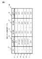
図5は、図2に記載の画像変換装置200において用いられる動きベクトル変換係数テーブルの一例を示す説明図である。
FIG. 5 is an explanatory diagram showing an example of a motion vector conversion coefficient table used in the
図5に示す動きベクトル変換係数テーブル300は、例えば動きベクトルレート変換部31に格納されるものである。動きベクトル変換係数テーブル300は、各々のステップを特定するための数値情報の記録領域51、動きベクトルレート変換部31に入力される50Hzの動きベクトルの記録領域53、及び該記録領域53に記録される個々の(50Hzの)動きベクトルに乗算される第1係数の記録領域55を備える。動きベクトル変換係数テーブル300は、上記に加えて、同じく上記記録領域53に記録される個々の(50Hzの)動きベクトルに乗算される第2係数の記録領域57、及び動きベクトルレート変換部31から出力される60Hzの動きベクトルの記録領域59をも備える。
The motion vector conversion coefficient table 300 illustrated in FIG. 5 is stored in the motion vector
各々の記録領域53に記録される情報は、各々の記録領域51に記録される情報に、各々の記録領域55に記録される情報は各々の記録領域53に記録される情報に、各々の記録領域57に記録される情報は各々の記録領域55に記録される情報に、各々の記録領域59に記録される情報は各々の記録領域57に記録される情報に、夫々対応せしめられている。
Information recorded in each
符号61で示す第1のステップでは、記録領域53には入力動きベクトルとして50Hzの動きベクトルMV1が、記録領域55には第1係数としてKA1が、記録領域59には出力動きベクトルとして60Hzの動きベクトルMVaが、夫々記録される。なお、第2係数が記録されるべき記録領域57には何も記録されていない。次に、符号63で示す第2のステップでは、記録領域53には入力動きベクトルとして50Hzの動きベクトルMV1、MV2が、記録領域55には第1係数としてKA2が、記録領域57には第2係数としてKB2が、記録領域59には出力動きベクトルとして60Hzの動きベクトルMVbが、夫々記録される。
In the first step denoted by
次に、符号65で示す第3のステップでは、記録領域53には入力動きベクトルとして50Hzの動きベクトルMV2、MV3が、記録領域55には第1係数としてKA3が、記録領域57には第2係数としてKB3が、記録領域59には出力動きベクトルとして60Hzの動きベクトルMVcが、夫々記録される。次に、符号67で示す第4のステップでは、記録領域53には入力動きベクトルとして50Hzの動きベクトルMV3、MV4が、記録領域55には第1係数としてKA4が、記録領域57には第2係数としてKB4が、記録領域59には出力動きベクトルとして60Hzの動きベクトルMVdが、夫々記録される。
Next, in a third step denoted by
次に、符号69で示す第5のステップでは、記録領域53には入力動きベクトルとして50Hzの動きベクトルMV4、MV5が、記録領域55には第1係数としてKA5が、記録領域57には第2係数としてKB5が、記録領域59には出力動きベクトルとして60Hzの動きベクトルMVeが、夫々記録される。更に、符号71で示す第6のステップでは、記録領域53には入力動きベクトルとして50Hzの動きベクトルMV5が、記録領域55には第1係数としてKA6が、記録領域59には出力動きベクトルとして60Hzの動きベクトルMVeが、夫々記録される。なお、第2係数が記録されるべき記録領域57には何も記録されていない。
Next, in a fifth step denoted by
上述したように、50Hzの映像信号のフレームレートを、60Hzの映像信号のフレームレートにレート変換することにより、50Hzの映像信号を、60Hzの映像信号に変換するに際しては、動きベクトル検出部27において検出した5フレーム分の動きベクトル(図4において、MV1(610)〜MV5(650)で示した50Hzの動きベクトル45)に対し、動きベクトルレート変換部31において6フレーム分の動きベクトル(図4において、MVa(710)〜MVf(760)で示した60Hzの動きベクトル47)を得ることになる。
As described above, when the 50 Hz video signal is converted into the 60 Hz video signal by converting the frame rate of the 50 Hz video signal to the frame rate of the 60 Hz video signal, the motion
動きベクトルレート変換部31における、50Hzの動きベクトルからの60Hzの動きベクトルへのレート変換の手順は、以下のようである。
The procedure of rate conversion from the 50 Hz motion vector to the 60 Hz motion vector in the motion vector
即ち、動きベクトル検出部27において検出した1フレーム分、又は、(時間的に)連続する2フレーム分の50Hzの動きベクトルに対し、動きベクトルレート変換部31において第1係数を乗じて得られた積、又は第1係数、及び第2係数を夫々乗じて得られた積同士の和を、60Hzの動きベクトルとする。例えば、動きベクトルレート変換部31への入力動きベクトルが、符号61で示した第1のステップにおける50Hzの動きベクトルMV1である場合には、動きベクトルレート変換部31からの出力動きベクトルMVaは、MV1とKA1との積である。また、動きベクトルレート変換部31への入力動きベクトルが、符号63で示した第2のステップにおける50Hzの動きベクトルMV1、MV2である場合には、動きベクトルレート変換部31からの出力動きベクトルMVbは、MV1とKA2との積に、MV2とKB2との積を足して得られる値(MV1・KA2+MV2・KB2)である。
In other words, the motion vector
また、動きベクトルレート変換部31への入力動きベクトルが、符号65で示した第3のステップにおける50Hzの動きベクトルMV2、MV3である場合には、動きベクトルレート変換部31からの出力動きベクトルMVcは、MV2とKA3との積に、MV3とKB3との積を足して得られる値(MV2・KA3+MV3・KB3)である。また、動きベクトルレート変換部31への入力動きベクトルが、符号67で示した第4のステップにおける50Hzの動きベクトルMV3、MV4である場合には、動きベクトルレート変換部31からの出力動きベクトルMVdは、MV3とKA4との積に、MV4とKB4との積を足して得られる値(MV3・KA4+MV4・KB4)である。
When the input motion vectors to the motion vector
また、動きベクトルレート変換部31への入力動きベクトルが、符号69で示した第5のステップにおける50Hzの動きベクトルMV4、MV5である場合には、動きベクトルレート変換部31からの出力動きベクトルMVeは、MV4とKA5との積に、MV5とKB5との積を足して得られる値(MV4・KA5+MV5・KB5)である。更に、動きベクトルレート変換部31への入力動きベクトルが、符号71で示した第6のステップにおける50Hzの動きベクトルMV5である場合には、動きベクトルレート変換部31からの出力動きベクトルMVfは、MV5とKA6との積である。
When the input motion vector to the motion vector
上述した第1係数と第2係数との間の比率は、時間軸上における50Hzの動きベクトル、及び60Hzの動きベクトルの位相関係に基づいて予め適宜な値に設定される。なお、動きベクトル変換係数テーブル300において、上述したステップの数、第1係数、及び第2係数の数等については、フレームレートや、動きベクトルのレート等のレート変換の条件に応じて、任意に変更することが可能である。 The ratio between the first coefficient and the second coefficient described above is set to an appropriate value in advance based on the phase relationship between the 50 Hz motion vector and the 60 Hz motion vector on the time axis. In the motion vector conversion coefficient table 300, the number of steps, the number of first coefficients, the number of second coefficients, and the like described above are arbitrarily determined according to rate conversion conditions such as a frame rate and a motion vector rate. It is possible to change.
図6は、動きベクトルレート変換部31に入力される50Hzの動きベクトルと、動きベクトルレート変換部31から出力される60Hzの動きベクトルとの関係を示す説明図である。
FIG. 6 is an explanatory diagram illustrating a relationship between a 50 Hz motion vector input to the motion vector
期間(即ち、50Hzの動きベクトル45を、60Hzの動きベクトル47にレート変換するに際してのレート変換処理の対象になる期間)TWにおいて、5フレーム分の50Hzの動きベクトル45から、6フレーム分の60Hzの動きベクトル47を得る場合、以下のような対応関係で、5フレーム分の50Hzの動きベクトルの各々と、6フレーム分の動きベクトルの各々とが、動きベクトルレート変換部31により参照される。
Period (i.e., a
即ち、60Hzの動きベクトル47であるMVa(710)を得るには、50Hzの動きベクトル45であるMV1(610)が、60Hzの動きベクトル47であるMVb(720)を得るには、50Hzの動きベクトル45であるMV1(610)、及びMV2(620)が、夫々参照される。また、60Hzの動きベクトル47であるMVc(730)を得るには、50Hzの動きベクトル45であるMV2(620)、及びMV3(630)が、60Hzの動きベクトル47であるMVd(740)を得るには、50Hzの動きベクトル45であるMV3(630)、及びMV4(640)が、夫々参照される。
That is, to obtain MVA (710) that is a
更に、60Hzの動きベクトル47であるMVe(750)を得るには、50Hzの動きベクトル45であるMV4(640)、及びMV5(650)が、60Hzの動きベクトル47であるMVf(760)を得るには、50Hzの動きベクトル45であるMV5(650)が、夫々参照される。動きベクトル検出部27は、動きベクトルレート変換部31により生成されるべき60Hzの動きベクトルの時間軸上の位置の関係で、何れの50Hzの動きベクトルを参照するかを決定する。例えば、60Hzの動きベクトルMVa(710)は、50Hzの動きベクトルMV1(610)に対してのみ、相関性(類似性)があるので、動きベクトルレート変換部31が60Hzの動きベクトルMVa(710)を生成するに際しては、50Hzの動きベクトルMV1(610)のみが参照の対象になる。
Furthermore, in order to obtain MVe (750) which is a
しかし、60Hzの動きベクトルMVb(720)は、50Hzの動きベクトルMV1(610)、及びMV2(620)に対して、60Hzの動きベクトルMVc(730)は、50Hzの動きベクトルMV2(620)、及びMV3(630)に対して、60Hzの動きベクトルMVd(740)は、50Hzの動きベクトルMV3(630)、及びMV4(640)に対して、60Hzの動きベクトルMVe(750)は、50Hzの動きベクトルMV4(640)、及びMV5(650)に対して、夫々相関性(類似性)がある。よって、60Hzの動きベクトルMVb(720)〜MVe(750)の生成に際しては、上述した態様で、夫々2つの50Hzの動きベクトルが参照されることになる。 However, 60 Hz motion vector MVb (720) is 50 Hz motion vector MV1 (610) and MV2 (620), while 60 Hz motion vector MVc (730) is 50 Hz motion vector MV2 (620), and For MV3 (630), a 60 Hz motion vector MVd (740) is for a 50 Hz motion vector MV3 (630), and for MV4 (640), a 60 Hz motion vector MVe (750) is a 50 Hz motion vector. There is a correlation (similarity) to MV4 (640) and MV5 (650), respectively. Therefore, when generating the 60 Hz motion vectors MVb (720) to MVe (750), two 50 Hz motion vectors are referred to in the above-described manner.
なお、図6において、矢印tは、時間の流れを示す。 In FIG. 6, an arrow t indicates the flow of time.
図7は、50Hzの動きベクトル45を、60Hzの動きベクトル47にレート変換するに際しての、動きベクトルレート変換部31において実行されるレート変換の手順を示す説明図である。
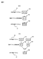
FIG. 7 is an explanatory diagram showing a rate conversion procedure executed by the motion vector
図7において、図7(a)は、図5で示した第1のステップ(61)、及び第6のステップ(71)におけるパラメータを用いる計算手順を示す。即ち、60Hzの動きベクトル47であるMVax(790)は、50Hzの動きベクトル45であるMV1x(770)に第1係数である動きベクトル変換係数KAx(780)を乗算することにより、求められる。図7(b)は、図5で示した第2のステップ(63)、第3のステップ(65)、第4のステップ(67)、及び第5のステップ(69)におけるパラメータを用いる計算手順を示す。即ち、60Hzの動きベクトル47であるMVbx(850)は、50Hzの動きベクトル45であるMV2x(810)と第1係数である動きベクトル変換係数KAx(780)との積に、50Hzの動きベクトル45であるMV3x(830)と第2係数である動きベクトル変換係数KBx(840)との積を加算することにより、求められる。
In FIG. 7, FIG. 7 (a) shows a calculation procedure using the parameters in the first step (61) and the sixth step (71) shown in FIG. That is, MVax (790), which is a
図8は、動きベクトルレート変換部31上での50Hzの動きベクトルと、60Hzの動きベクトルとの配置関係の一例を示す模式図である。
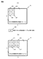
FIG. 8 is a schematic diagram illustrating an example of an arrangement relationship between a 50 Hz motion vector and a 60 Hz motion vector on the motion vector
図8では、図5で示した第1のステップ(61)での計算手順を用いた場合の、動きベクトルレート変換部31における50Hzの動きベクトル(45)と、60Hzの動きベクトル(47)との配置関係の一例を示す。
In FIG. 8, when using the calculation procedure in the first step (61) shown in FIG. 5, the 50 Hz motion vector (45) and the 60 Hz motion vector (47) in the motion vector
図8において、図8(a)は、動きベクトルレート変換部31上での50Hzの動きベクトルの配置関係の一例を示す。図8(a)において、50Hzの(映像信号の)画像(フレーム)73は、水平方向にX画素、垂直方向にY画素で構成される。フレーム73において、左上隅寄りの4点の画素に夫々対応する4個の50Hzの動きベクトルZ1(901)、Z2(903)、Z3(905)、及びZ4(907)に注目する。また、この場合の(図5で示した)動きベクトル変換係数テーブル300における第1係数がKx(909)に設定されているものと仮定する。なお、図8(a)で示した50Hzの(映像信号の)画像(フレーム)73は、動きベクトルレート変換部31への入力映像信号の画像(フレーム)である。
In FIG. 8, FIG. 8A shows an example of the arrangement relationship of 50 Hz motion vectors on the motion vector
図8(b)は、動きベクトルレート変換部31上での60Hzの動きベクトルの配置関係の一例を示す。図8(b)において、60Hzの(映像信号の)画像(フレーム)75も、上述した50Hzの(映像信号の)画像(フレーム)73におけると同様に、水平方向にX画素、垂直方向にY画素で構成される。即ち、X・Yで示される画素数分の動きベクトルが、60Hzの動きベクトルとして、動きベクトルレート変換部31から出力される。フレーム75において、左上隅寄りの4点の画素に夫々対応する4個の60Hzの動きベクトルは、Z1・Kx(911)、Z2・Kx(913)、Z3・Kx(915)、及びZ4・Kx(917)で示される。
FIG. 8B shows an example of an arrangement relationship of 60 Hz motion vectors on the motion vector
上記60Hzの動きベクトルZ1・Kx(911)、Z2・Kx(913)、Z3・Kx(915)、及びZ4・Kx(917)が、動きベクトルレート変換部31から出力される。
The 60 Hz
図9は、50Hzの映像信号のフレームと、60Hzの映像信号のフレームとの時間軸上での関係、及び50Hzの動きベクトルと、60Hzの動きベクトルとの時間軸上での関係、を夫々示す模式図である。 FIG. 9 shows the relationship between the 50 Hz video signal frame and the 60 Hz video signal frame on the time axis, and the relationship between the 50 Hz motion vector and the 60 Hz motion vector on the time axis. It is a schematic diagram.
図9では、上述した期間TWにおいて、画像レート変換部21が、5フレーム分の50Hzの映像信号から、6フレーム分の60Hzの映像信号を得るためのレート変換動作を行う場合、及び動きベクトルレート変換部31が、5フレーム分の50Hzの動きベクトルから、6フレーム分の60Hzの動きベクトルを得るためのレート変換動作を行う場合、を例に挙げて説明する。
In FIG. 9, in the above-described period TW , the image
図4においても説明したように、50Hzの動きベクトルは、50Hzの映像信号における連続する(時間的に見て)前後2つのフレームを参照し、該2つのフレームの間で、所定の領域内での平面座標が同一である画素同士の動きに対応するベクトルとして生成される。例えば、50Hzの動きベクトルMV1(610)は、50HzのフレームA(410)と、50HzのフレームB(420)と、を参照することにより、50Hzの動きベクトルMV2(620)は、50HzのフレームB(420)と、50HzのフレームC(430)と、を参照することにより、夫々生成される。 As described in FIG. 4, the 50 Hz motion vector refers to two consecutive frames (in terms of time) in the 50 Hz video signal, and within a predetermined area between the two frames. Are generated as vectors corresponding to the movement of pixels having the same plane coordinates. For example, the 50 Hz motion vector MV1 (610) is obtained by referring to the 50 Hz frame A (410) and the 50 Hz frame B (420), so that the 50 Hz motion vector MV2 (620) is obtained from the 50 Hz frame B (420). (420) and 50 Hz frame C (430), respectively.
また、50Hzの動きベクトルMV3(630)は、50HzのフレームC(430)と、50HzのフレームD(440)と、を参照することにより、50Hzの動きベクトルMV4(640)は、50HzのフレームD(440)と、50HzのフレームE(450)と、を参照することにより、夫々生成される。更に、50Hzの動きベクトルMV5(650)は、50HzのフレームE(450)と、50HzのフレームF(460)と、を参照することにより、生成される。 Further, the 50 Hz motion vector MV3 (630) is obtained by referring to the 50 Hz frame C (430) and the 50 Hz frame D (440), so that the 50 Hz motion vector MV4 (640) is obtained from the 50 Hz frame D. (440) and 50 Hz frame E (450), respectively, are generated. Further, the 50 Hz motion vector MV5 (650) is generated by referring to the 50 Hz frame E (450) and the 50 Hz frame F (460).
図9においても、図4において示したような、50Hzの映像信号における連続する(時間的に見て)前後2つのフレームの、画像レート変換部21、及び動きベクトル検出部27による同時参照が可能なように、1つの50Hzの映像信号が、画像記憶部19から所謂リアルタイムで出力されるのみならず、1フレーム分遅延された状態でも出力される。しかし、図9では、図示と説明の都合により、図4で示したように、同一の50Hzの映像信号を1フレーム分遅延させたものと、そうでないものとを別々に表現した記載形式にはしていない。
9, as shown in FIG. 4, the image
5フレーム分の50Hzの動きベクトル45(即ち、MV1(610)、MV2(620)、MV3(630)、MV4(640)、及びMV5(650)から、6フレーム分の60Hzの動きベクトル47(即ち、MVa(710)、MVb(720)、MVc(730)、MVd(740)、MVe(750)、及びMVf(760))を得るための、50Hzの動きベクトル45の各々と、60Hzの動きベクトル47の各々との対応関係については、既述のとおりであるので、ここでの詳細な説明は省略する。
From a
画像レート変換部21が、5フレーム分の50Hzの映像信号から、6フレーム分の60Hzの映像信号を得るための手順は、以下のとおりである。
The procedure for the image
即ち、まず、期間TWの始期と同期する50HzのフレームA(410)については、そのまま60Hzのフレームa(810)として出力する。次に、50HzのフレームB(420)、50HzのフレームC(430)、50HzのフレームD(440)、50HzのフレームE(450)と、60Hzのフレームb(820)、60Hzのフレームc(830)、60Hzのフレームd(840)、60Hzのフレームe(850)、及び60Hzのフレームf(860)と、を比較対照すると、60Hzのフレームb(820)〜60Hzのフレームf(860)の何れも、夫々対応関係にある50HzのフレームB(420)〜50HzのフレームE(450)と、時間軸上において同期していない。 That is, first, for the frame A (410) of 50Hz to synchronize the beginning of the period T W, and outputs it as a frame a (810) of 60 Hz. Next, 50 Hz frame B (420), 50 Hz frame C (430), 50 Hz frame D (440), 50 Hz frame E (450), 60 Hz frame b (820), 60 Hz frame c (830) ), 60 Hz frame d (840), 60 Hz frame e (850), and 60 Hz frame f (860) are compared, and any of 60 Hz frame b (820) to 60 Hz frame f (860) However, they are not synchronized on the time axis with the 50 Hz frame B (420) to the 50 Hz frame E (450), which are in a corresponding relationship.
そのため、画像レート変換部21が、50Hzのフレームから60Hzのフレームを生成することにより、50Hzの映像信号のフレームレートを、60Hzの映像信号のフレームレートにレート変換するには、時間的に連続する前後2つの50Hzのフレームから、所定のアルゴリズムに従って合成したフレームを、60Hzのフレームとして出力することになる。例えば、60Hzのフレームb(820)は、時間軸上において該60Hzのフレームb(820)に対し前後に近接する2つの50HzのフレームA(410)、フレームB(420)から合成されたフレームである。また、60Hzのフレームc(830)は、時間軸上において該60Hzのフレームc(830)に対し前後に近接する2つの50HzのフレームB(420)、フレームC(430)から合成されたフレームである。
Therefore, the image
また、60Hzのフレームd(840)は、時間軸上において該60Hzのフレームd(840)に対し前後に近接する2つの50HzのフレームC(430)、フレームD(440)から合成されたフレームである。また、60Hzのフレームe(850)は、時間軸上において該60Hzのフレームd(850)に対し前後に近接する2つの50HzのフレームD(440)、フレームE(450)から合成されたフレームである。更に、60Hzのフレームf(860)は、時間軸上において該60Hzのフレームf(860)に対し前後に近接する2つの50HzのフレームE(450)、フレームF(460)から合成されたフレームである。 The 60 Hz frame d (840) is a frame synthesized from two 50 Hz frames C (430) and D (440) that are adjacent to the 60 Hz frame d (840) on the time axis. is there. The 60 Hz frame e (850) is a frame synthesized from two 50 Hz frames D (440) and E (450) that are adjacent to the 60 Hz frame d (850) on the time axis. is there. Further, the 60 Hz frame f (860) is a frame synthesized from two 50 Hz frames E (450) and F (460) which are adjacent to the 60 Hz frame f (860) on the time axis. is there.
既述のように、図2、図3で示した画像補正部23では、画像レート変換部21から出力される60Hzのフレームの画像補正が、動きベクトルレート変換部31から出力される60Hzの動きベクトルに基づいて行われる。即ち、図9に示した60Hzのフレームa(810)〜60Hzのフレームf(860)の各々は、対応する60Hzの動きベクトルMVa(710)〜60Hzの動きベクトルMVf(760)の各々が参照されることによって、画像補正が施される。
As described above, in the
例えば、60Hzのフレームa(810)は、60Hzの動きベクトルMVa(710)により、60Hzのフレームb(820)は、60Hzの動きベクトルMVb(720)により、60Hzのフレームc(830)は、60Hzの動きベクトルMVc(730)により、夫々画像補正が施される。また、60Hzのフレームd(840)は、60Hzの動きベクトルMVd(740)により、60Hzのフレームe(850)は、60Hzの動きベクトルMVe(750)により、60Hzのフレームf(860)は、60Hzの動きベクトルMVf(760)により、夫々画像補正が施される。 For example, a 60 Hz frame a (810) is obtained from a 60 Hz motion vector MVA (710), a 60 Hz frame b (820) is obtained from a 60 Hz motion vector MVb (720), and a 60 Hz frame c (830) is obtained from 60 Hz. Each of the motion vectors MVc (730) performs image correction. The 60 Hz frame d (840) is obtained from the 60 Hz motion vector MVd (740), the 60 Hz frame e (850) is obtained from the 60 Hz motion vector MVe (750), and the 60 Hz frame f (860) is obtained from the 60 Hz frame. Each of the motion vectors MVf (760) performs image correction.
図10は、動きベクトルレート変換部31においてレート変換されて得られる(60Hzの)動きベクトル(47)の、動きベクトルレート変換部31からの出力タイミングの一例を示す説明図である。
FIG. 10 is an explanatory diagram illustrating an example of the output timing from the motion vector
動きベクトルレート変換部31に入力される50Hzの動きベクトルと、動きベクトルレート変換部31から出力される60Hzの動きベクトルとの関係は、図6において説明したとおりであるので、ここでの説明は省略する。
The relationship between the 50 Hz motion vector input to the motion vector
動きベクトルレート変換部31における60Hzの動きベクトル47の生成は、動きベクトル検出部27が、画像記憶部19より出力される50Hzの(映像信号の)フレーム中から50Hzの動きベクトル45を検出して、該50Hzの動きベクトル45を、動きベクトル検出部27から出力するタイミングに同期している。60Hzの動きベクトル47の、動きベクトルレート変換部31からの出力タイミングについて、上述した期間(即ち、50Hzの動きベクトル45を、60Hzの動きベクトル47にレート変換するに際してのレート変換処理の対象になる期間)TWを例にとって説明する。
In the generation of the 60
例えば、60Hzの動きベクトルMVa(710)の生成タイミングは、50Hzの動きベクトルMV1(610)が、動きベクトル検出部27から動きベクトル記憶部29を通じて動きベクトルレート変換部31に出力されるタイミングに同期するように設定される。次に、60Hzの動きベクトルMVb(720)の生成タイミングは、動きベクトル記憶部29内に設定される動きベクトル一時記憶領域77に一時的に記憶されている50Hzの動きベクトルMV1(610)が、動きベクトルレート変換部31に出力された後、50Hzの動きベクトルMV2(620)が、動きベクトルレート変換部31に出力されるタイミングに同期するように設定される。
For example, the generation timing of the 60 Hz motion vector MVA (710) is synchronized with the timing at which the 50 Hz motion vector MV1 (610) is output from the motion
次に、60Hzの動きベクトルMVc(730)の生成タイミングは、動きベクトル一時記憶領域77に一時的に記憶されている50Hzの動きベクトルMV2(620)が、動きベクトルレート変換部31に出力された後、50Hzの動きベクトルMV3(630)が、動きベクトルレート変換部31に出力されるタイミングに同期するように設定される。次に、60Hzの動きベクトルMVd(740)の生成タイミングは、動きベクトル一時記憶領域77に一時的に記憶されている50Hzの動きベクトルMV3(630)が、動きベクトルレート変換部31に出力された後、50Hzの動きベクトルMV4(640)が、動きベクトルレート変換部31に出力されるタイミングに同期するように設定される。
Next, regarding the generation timing of the 60 Hz motion vector MVc (730), the 50 Hz motion vector MV 2 (620) temporarily stored in the motion vector
次に、60Hzの動きベクトルMVe(750)の生成タイミングは、動きベクトル一時記憶領域77に一時的に記憶されている50Hzの動きベクトルMV4(640)が、動きベクトルレート変換部31に出力された後、50Hzの動きベクトルMV5(650)が、動きベクトルレート変換部31に出力されるタイミングに同期するように設定される。更に、60Hzの動きベクトルMVf(760)の生成タイミングは、50Hzの動きベクトルMV5(650)が、動きベクトル検出部27から動きベクトル記憶部29を通じて動きベクトルレート変換部31に出力されるタイミングに同期するように設定される。
Next, regarding the generation timing of the 60 Hz motion vector MVe (750), the 50 Hz motion vector MV4 (640) temporarily stored in the motion vector
図10から明らかなように、50Hzの動きベクトル45であるMV4(640)、MV5(650)から60Hzの動きベクトル47であるMVe(750)への変換、及び50Hzの動きベクトル45であるMV5(650)から60Hzの動きベクトル47であるMVf(760)への変換を除き、50Hzの動きベクトル45から60Hzの動きベクトル47へのレート変換においては、1つの動きベクトルのレート変換(即ち、1つの50Hzの動きベクトルの1つの60Hzの動きベクトルへの変換)処理に要する最大時間長は、TW/5である。しかし、50Hzの動きベクトル45であるMV4(640)、MV5(650)から60Hzの動きベクトル47であるMVe(750)への変換、及び50Hzの動きベクトル45であるMV5(650)から60Hzの動きベクトル47であるMVf(760)への変換に際しては、上記2つの60Hzの動きベクトルMVe(750)、MVf(760)への変換が、最後の期間TW/5内において、両者同時に行われる。
As is apparent from FIG. 10, MV4 (640), which is a 50
上述した内容から明らかなように、50Hzの動きベクトル45から60Hzの動きベクトル47を生成する場合において、60Hzの動きベクトル47であるMVb(720)〜MVe(750)を生成する手順では、動きベクトルレート変換部31は、新たに入力した50Hzの動きベクトル45の他に、時間的にその1つ前の動きベクトルのレート変換処理で入力した50Hzの動きベクトルをも参照する必要がある。そのため、動きベクトル検出部27から50Hzの動きベクトル45が出力されると、該50Hzの動きベクトル45は、動きベクトル記憶部29を通じて動きベクトルレート変換部31に出力されるのみならず、既述のように、動きベクトル記憶部29内に設定される動きベクトル一時記憶領域77に一時的に記憶される。そして、例えば60Hzの動きベクトルMVb(720)が生成される場合には、その1つ前で生成された(60Hzの動きベクトル47である)MVa(710)の生成時に、動きベクトル一時記憶領域77に一時的に記憶された(50Hzの動きベクトル45である)MV1(610)が、動きベクトルレート変換部31によって動きベクトル一時記憶領域77から読み出されることになる。60Hzの動きベクトルMVc(730)〜MVe(750)の生成に際しても、上記と同様である。
As is apparent from the above description, in the case of generating the 60
図11は、動きベクトルレート変換部31においてレート変換されて得られる(60Hzの)動きベクトル47の、動きベクトルレート変換部31からの出力タイミングの別の一例を示す説明図である。
FIG. 11 is an explanatory diagram showing another example of the output timing from the motion vector
図10では、上述した期間(即ち、50Hzの動きベクトル45を、60Hzの動きベクトル47にレート変換するに際してのレート変換処理の対象になる期間)TWにおいて、最後の期間であるTW/5、即ち、60Hzの動きベクトルMVe(750)、及びMVf(760)を生成するに際してのみ、同一の50Hzの動きベクトル45であるMV5(650)を2回参照していた。しかし、50Hzの動きベクトルを、画像記憶部19に記憶されている50Hzの映像信号のフレームから検出して、動きベクトルレート変換部31に出力する回路系を、例えばLSI化する場合、同一データ量の読み出し動作を、なるべく所定周期毎に繰り返す構成にした方が、回路設計が容易であり、且つ、回路動作的にも効率が良い。
In FIG. 10, T W / 5, which is the last period in the above-described period (that is, a period subjected to rate conversion processing when the 50
そこで、上記に鑑みて、図11に示す例では、60Hzの動きベクトル47である、MVf(760)については、その1つ前の(60Hzの動きベクトル47である)MVe(750)の複写を用いることとした。このような手法を採用することによって、動きベクトルレート変換部31が(50Hzの動きベクトル45である)MV5(650)を参照する回数が2回から1回に減少するので、上述した(LSI化された)回路系における50Hzの動きベクトル45の読み出し動作の周期性を保持することが可能になる。
Therefore, in view of the above, in the example shown in FIG. 11, with respect to MVf (760), which is the 60
図11で示した手法では、動きベクトルレート変換部31による(50Hzの動きベクトル45である)MV5(650)に基づく(60Hzの動きベクトル47である)MVf(760)の生成動作、即ち、動きベクトルのレート変換動作を省略している。そのため、図11で示した手法を用いて得られた結果と、図10で示したような変換処理の手法を用いて得られた結果とでは、厳密に言えば相違点がある。
In the method shown in FIG. 11, the motion vector
しかし、通常の自然動画においては、(時間的に)隣り合うフレーム同士の間では、画像同士の相関関係が強いことが一般的に知られており、そのため、(時間的に)隣り合うフレーム同士の間では、同様に動きベクトル同士の相関関係も強いであろうと推測される。よって、上述した50Hzの動きベクトル45の所定の読み出し周期において、一部の50Hzの動きベクトルの複写を、複数の60Hzの動きベクトルとして用いることとしても、画像補正部23での、それら60Hzの動きベクトル47を用いた(フレームレート変換が行われることにより得られた)60Hzの映像信号の画像補正への影響を、最小限に止めることができる。
However, it is generally known that in a normal natural video, there is a strong correlation between images (temporally) between adjacent frames. Similarly, it is presumed that the correlation between motion vectors will be strong as well. Therefore, even if a copy of some 50 Hz motion vectors is used as a plurality of 60 Hz motion vectors in the predetermined readout cycle of the 50
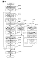
図12は、図2に記載の画像変換装置200が、画像変換処理を行うに際しての画像変換装置200を構成する各部の処理動作を示すフローチャートである。
FIG. 12 is a flowchart showing the processing operation of each part constituting the
図12において、まず、画像変換装置200に入力される映像信号のフレームレートと、画像変換装置200から出力される映像信号のフレームレートとの関係から、フレームレート、及び動きベクトルのレートの変換周期FNを設定する。一例として、50Hzの映像信号から60Hzの映像信号へのレート変換の周期を“5”に設定する(ステップS101)。次に、上記設定された変換周期内における時間軸上の位置を認識するための周期カウンタFCNTのカウント値を“1”にセットする(ステップS102)。次に、動きベクトル検出部27が、画像記憶部19より時間的に連続する2フレーム分の50Hzの映像信号を入力し、そこから50Hzの動きベクトルMVnを検出する(ステップS103)。
In FIG. 12, first, from the relationship between the frame rate of the video signal input to the
そして、動きベクトル検出部27は、該検出した50Hzの動きベクトルMVnにつき、動きベクトル記憶部29を通じて直ちに動きベクトルレート変換部31に出力する処理動作と、上記50Hzの動きベクトルMVnを1フレーム分遅延させて動きベクトルレート変換部31に出力すべく、上記50Hzの動きベクトルMVnを、動きベクトル記憶部29の動きベクトル一時記憶領域77に格納する処理動作と、を並行して行う(ステップS104)。次に、動きベクトルレート変換部31が、周期カウンタFCNTのカウント値が“1”かどうかチェックする(ステップS105)。
The motion
該チェックの結果、FCNT=1であれば(ステップS105でYES)、動きベクトルレート変換部31は、図5で示した動きベクトル変換テーブル300から、(50Hzの動きベクトル45を60Hzの動きベクトル47にレート変換するのに必要な)第1係数KAnを読み出す(ステップS106)。そして、この読み出した第1係数Kanを用いて、ステップS103で動きベクトル検出部27が検出した50Hzの動きベクトルMVnに対し、レート変換をするための演算処理(MVx=MVn・KAn)を行い、60Hzの動きベクトルMVxを求める(ステップS107)。
If FCNT = 1 as a result of the check (YES in step S105), the motion vector
上記60Hzの動きベクトルMVxが、動きベクトルレート変換部31から出力されると、画像補正部23は、上記60Hzの動きベクトルMVxを用いて、画像レート変換部21から出力される60Hzの映像信号に対し、所定のアルゴリズムに従って画像補正処理を施す(ステップS108)。そして、画像補正部23は、該画像補正処理を施した後の60Hzの上記映像信号を、画像出力部25に出力する(ステップS109)。次に、周期カウンタFCNTのカウント値がインクリメント(+1)されると共に(ステップS110)、周期カウンタFCNTのカウント値が、ステップS101で設定した変換周期FNよりも小さいか等しいか、それとも周期カウンタFCNTのカウント値が変換周期FNよりも大きいかがチェックされる(ステップS111)。該チェックの結果、FCNT≦FNであると判断された場合には、ステップS103で示した処理動作に復帰し、FCNT>FNであると判断された場合には、周期カウンタFCNTをリセットして(ステップS112)、画像変換装置200による一連の処理動作が終了する。
When the 60 Hz motion vector MVx is output from the motion vector
この場合、ステップS110でインクリメント(+1)される前の周期カウンタFCNTのカウント値は“1”であるから、ステップS111における周期カウンタFCNTのカウント値は2である。よって、周期カウンタFCNTのカウント値はリセットされることはなく、ステップS103に移行することになる。 In this case, since the count value of the cycle counter FCNT before being incremented (+1) in step S110 is “1”, the count value of the cycle counter FCNT in step S111 is 2. Therefore, the count value of the cycle counter FCNT is not reset, and the process proceeds to step S103.
ステップS103において、動きベクトル検出部27が、時間的に連続する2フレーム分の50Hzの映像信号から50Hzの動きベクトルMVnを検出し、ステップS104において、上記50Hzの動きベクトルMVnを直ちに動きベクトルレート変換部31に出力する処理、及び1フレーム分遅延させて動きベクトルレート変換部31に出力するための処理を行った後、FCNTが“1”でないと判断された場合には(ステップS105でNO)、次に、周期カウンタFCNTのカウント値が“5”かどうかがチェックされる(ステップS113)。
In step S103, the motion
該チェックの結果、FCNT=5でなければ(ステップS113でNO)、周期カウンタFCNTのカウント値は、2乃至4の何れかである筈である。そこで、動きベクトルレート変換部31は、動きベクトル記憶部29の動きベクトル一時記憶領域77から1つ前のレート変換周期において保存されたものである50Hzの動きベクトルMVn-1を読み出し(ステップS115)、動きベクトル変換テーブル300から上述した第1係数KAnを読み出す(ステップS117)。
As a result of the check, if FCNT = 5 is not satisfied (NO in step S113), the count value of the cycle counter FCNT should be one of 2 to 4. Therefore, the motion vector
次に、動きベクトル変換テーブル300から(50Hzの動きベクトル45を60Hzの動きベクトル47にレート変換するのに必要な)第2係数KBnを読み出す(ステップS118)。そして、ステップS103で読み込んだ50Hzの動きベクトルMVnと、ステップS115で読み込んだ1つ前のレート変換周期での50Hzの動きベクトルMVn-1と、ステップS117で読み込んだ第1係数Kanと、ステップS118で読み込んだ第2係数KBnと、を用いて、60Hzの動きベクトルMVxを求める。即ち、動きベクトルレート変換部31は、MVx=(MVn-1×KAn)+(MVn×KBn)を演算する(ステップS118)。このステップS118での演算処理が終了すると、ステップS108で示した処理動作に移行することになる。
Next, the second coefficient KBn (necessary for rate-converting the 50
この場合、ステップS110でインクリメント(+1)される前の周期カウンタFCNTのカウント値は“2乃至4”であるから、ステップS111における周期カウンタFCNTのカウント値は“3乃至5”である。よって、周期カウンタFCNTのカウント値がリセットされることはなく、ステップS103に移行することになる。 In this case, since the count value of the cycle counter FCNT before being incremented (+1) in step S110 is “2 to 4”, the count value of the cycle counter FCNT in step S111 is “3 to 5”. Therefore, the count value of the cycle counter FCNT is not reset, and the process proceeds to step S103.
ステップS103にて示した処理、ステップS104にて示した処理、及びステップS105で示した処理を行った後、FCNTが“5”であると判断された場合には(ステップS113でYES)、動きベクトルレート変換部31は、それより1つ前のレート変換周期(即ち、FCNT=4)における60Hzの動きベクトルであるMVxを複写する。そして、該複写した60Hzの動きベクトルMVxを、FCNT=5における60Hzの動きベクトルとする(ステップS119)。このステップS119で示した処理が終了すると、ステップS108で示した処理動作に移行する。
If it is determined that FCNT is “5” after performing the process shown in step S103, the process shown in step S104, and the process shown in step S105 (YES in step S113), the motion The vector
この場合、ステップS110でインクリメント(+1)される前の周期カウンタFCNTのカウント値は“5”であるから、ステップS111における周期カウンタFCNTのカウント値は“6”である。よって、周期カウンタFCNTのカウント値“6”がリセットされ(ステップS112)、一連の処理動作が終了することになる。 In this case, since the count value of the cycle counter FCNT before being incremented (+1) in step S110 is “5”, the count value of the cycle counter FCNT in step S111 is “6”. Therefore, the count value “6” of the cycle counter FCNT is reset (step S112), and a series of processing operations is completed.
図13は、動きベクトル記憶部29に設定される動きベクトル一時記憶領域77に格納されるべき50Hzの動きベクトルの間引き処理の一例を示す説明図である。
FIG. 13 is an explanatory diagram showing an example of a 50 Hz motion vector thinning process to be stored in the motion vector
図13に示す50Hzの動きベクトルの間引き処理は、動きベクトル一時記憶領域77の記憶容量を削減するためのもので、動きベクトル一時記憶領域77に格納されるべき50Hzの動きベクトルのデータ量が、所定の手順で間引かれる。例えば、50Hzの動きベクトルMV1(610)をレート変換することにより60Hzの動きベクトルMVa(710)が生成される際に、該動きベクトルMV1(610)に対し、動きベクトル間引き処理121を施すことにより得られた50Hzの動きベクトルSMV1(123)が、動きベクトル一時記憶領域77に格納される。
The 50 Hz motion vector thinning process shown in FIG. 13 is for reducing the storage capacity of the motion vector
そして、該処理動作よりも1つ後のレート変換周期において、新たな60Hzの動きベクトルMVb(720)が生成される際に、上記50Hzの動きベクトルSMV1(123)に対し、動きベクトル復元処理125が施されることにより、上記50Hzの動きベクトルMV1(610)が復元される。この動きベクトルMV1(610)と、上記1つ後の変換周期において新たに読み込まれる50Hzの動きベクトルMV2(620)とにより、動きベクトルレート変換部31において、上記新たな60Hzの動きベクトルMVb(720)が生成されることになる。
Then, when a new 60 Hz motion vector MVb (720) is generated in the rate conversion cycle one time after the processing operation, the motion
図14は、図13にて示した50Hzの動きベクトルMV1の間引き処理、及び間引き処理された50Hzの動きベクトルMV1の復元処理における動作を示す説明図である。 FIG. 14 is an explanatory diagram showing operations in the thinning process of the 50 Hz motion vector MV1 and the restoration process of the thinned 50 Hz motion vector MV1 shown in FIG.
図14において、図14(a)、及び図14(b)は、図13で示した動きベクトル間引き処理121にて、50Hzの動きベクトルMVnのデータ量を横方向、及び縦方向に夫々1/2ずつ画素数を間引くことにより、合計で50Hzの動きベクトルMVnにおける元の画素数の1/4にまで間引く場合の処理動作の一例を、模式的に示している。
14 (a) and 14 (b), in the motion
横方向の画素数がX、縦方向の画素数がYで、全体としてX・Yの画素数を有する50Hzの映像信号の画像(フレーム)73において、左上隅寄りの4点の画素に夫々対応する4個の50Hzの動きベクトルZ1(901)、Z2(903)、Z3(905)、及びZ4(907)に注目する。動きベクトル間引き処理121では、4個の(50Hzの)動きベクトルZ1(901)、Z2(903)、Z3(905)、及びZ4(907)の値の平均値(平均ベクトル値)であるZy(931)を求める処理と、該Zy(931)を代表ベクトルとして、例えば上述した動きベクトル記憶部29の動きベクトル一時記憶領域77に格納する処理と、が行われる。動きベクトル間引き処理121では、上記2つの処理が、50Hzの映像信号の画像(フレーム)73を構成する全ての画素について行われる。
The number of pixels in the horizontal direction is X, the number of pixels in the vertical direction is Y, and in the image (frame) 73 of a 50 Hz video signal having the number of X and Y as a whole, it corresponds to four pixels near the upper left corner respectively. Note the four 50 Hz motion vectors Z1 (901), Z2 (903), Z3 (905), and Z4 (907). In the motion vector thinning-out
その結果として、図13(b)に示すような、データ量が1/4に間引きされた50Hzの動きベクトルZy(931)を持つ50Hzの映像信号の画像(フレーム)127が生成される。この50Hzの映像信号の画像(フレーム)127は、縦方向にY/2の画素数を、横方向にX/2の画素数を、夫々持つ画像(フレーム)である。 As a result, as shown in FIG. 13B, an image (frame) 127 of a 50 Hz video signal having a 50 Hz motion vector Zy (931) thinned by ¼ is generated. The image (frame) 127 of the video signal of 50 Hz is an image (frame) having Y / 2 pixels in the vertical direction and X / 2 pixels in the horizontal direction.
図14において、図14(b)、及び図14(c)は、図13で示した動きベクトル復元処理125にて、間引き処理された50Hzの動きベクトルZy(931)から、動きベクトル間引き処理121により間引き処理が行われる前の各々の(50Hzの)動きベクトルZ1(901)〜Z4(907)を復元するに際しての処理動作の一例を、模式的に示している。即ち、動きベクトル復元処理125では、間引きが行われる前の各々の動きベクトルZ1(901)〜Z4(907)に係わる4個の画素と同一の4個の画素に対し、1つの代表ベクトルZy(931)を夫々複写することにより、図14(c)において、符号129で示す50Hzの映像信号の画像(フレーム)におけるように、間引き前と同一の50Hzの動きベクトルのデータ量が復元される。
14 (b) and 14 (c), the motion
図14に示した例では、50Hzの動きベクトルの間引き量は、合計で元の50Hzの動きベクトルのデータ量の1/4に間引く場合における処理動作の例を示した。しかし、これは動きベクトルのデータ量の間引き処理の一例であり、50Hzの映像信号の画像(フレーム)における横方向の各画素に係わる動きベクトル、及び縦方向の各画素に係わる動きベクトルの間引き量は、任意に設定して差し支えない。動きベクトルの間引き量を大きく設定した場合、動きベクトルの復元処理に際しての、復元処理後の動きベクトル値の精度低下が想定されるが、動きベクトルの間引き量は、動きベクトル値の精度、動きベクトル一時記憶領域77の記憶容量の何れに重きを置くかに応じて任意に設定して差し支えない。
In the example shown in FIG. 14, the example of the processing operation in the case where the thinning-out amount of the 50 Hz motion vector is thinned to ¼ of the total data amount of the original 50 Hz motion vector is shown. However, this is an example of the decimation process of the motion vector data amount, and the decimation amount of the motion vector related to each pixel in the horizontal direction and the motion vector related to each pixel in the vertical direction in the image (frame) of the 50 Hz video signal. Can be set arbitrarily. When the motion vector thinning amount is set to a large value, the accuracy of the motion vector value after the restoration processing is assumed to be reduced during the motion vector restoration processing, but the motion vector thinning amount is determined based on the accuracy of the motion vector value, the motion vector. The storage capacity of the
上述した本発明の一実施形態に係る画像変換装置200では、50Hzの映像信号を60Hzの映像信号にレート変換して出力する場合を例にとって説明したが、本発明の一実施形態に係る画像変換装置200は、50Hzの映像信号を、60Hzの映像信号にレート変換する場合のみに適用範囲が限定されるものではなく、50Hz以外の映像信号を、60Hz以外の映像信号にレート変換する場合にも、当然に適用が可能である。即ち、映像信号のフレームレートに関する標準規格は、複数存在しており、それらの何れのフレームレートの映像信号を入力映像信号、出力映像信号とする組み合わせにおいても、上記画像変換装置200は適用が可能である。
In the
入力映像信号のフレームレートと、出力映像信号のフレームレートとの組み合わせの他の例としては、24Hzの入力映像信号と60Hzの出力映像信号との組み合わせ、30Hzの入力映像信号と60Hzの出力映像信号との組み合わせ、50Hzの入力映像信号と100Hzの出力映像信号との組み合わせ、及び60Hzの入力映像信号と120Hzの出力映像信号との組み合わせ、等が挙げられる。 Other examples of combinations of the frame rate of the input video signal and the frame rate of the output video signal include a combination of a 24 Hz input video signal and a 60 Hz output video signal, a 30 Hz input video signal and a 60 Hz output video signal. , A combination of a 50 Hz input video signal and a 100 Hz output video signal, a combination of a 60 Hz input video signal and a 120 Hz output video signal, and the like.
以上、本発明の好適な実施形態を説明したが、これは本発明の説明のための例示であって、本発明の範囲をこの実施形態にのみ限定する趣旨ではない。本発明は、他の種々の形態でも実施することが可能である。 The preferred embodiment of the present invention has been described above, but this is an example for explaining the present invention, and the scope of the present invention is not limited to this embodiment. The present invention can be implemented in various other forms.
1 映像入/出力部
3 ユーザI/F部
5 録画/再生部
7 映像コンテンツ蓄積部
9 映像信号処理部
11 プラズマパネルディスプレイ
13 音声信号処理部
15 スピーカ
17 画像入力部
19 画像記憶部
21 画像レート変換部
23 画像補正部
25 画像出力部
27 動きベクトル検出部
29 動きベクトル記憶部
31 動きベクトルレート変換部
33 入力フレームレート検出部
35 出力フレームレート値保持部
37 入/出力フレームレート制御部
100 ディジタルTV受信機
200 画像変換装置
300 動きベクトル変換係数テーブル
DESCRIPTION OF
Claims (5)
前記第1の映像信号から、第1の動きベクトルを検出する動きベクトル検出部と、
前記第1の動きベクトルから前記第2のフレームレートと同一レートの第2の動きベクトルを生成する動きベクトルレート変換部と、
前記第2の映像信号を、前記第2の動きベクトルを利用して補正する映像信号補正部とを備え、
前記動きベクトルレート変換部は、前記第2の動きベクトルを求めるフレームに対して時間的に前後に位置する前記第1の映像信号の連続する2つのフレームの動きベクトルを使って前記第2の動きベクトルを生成し、
前記動きベクトルレート変換部は、前記第1の映像信号の連続する2つのフレームの動きベクトルに、第1の係数及び第2の係数を掛けて足し合わせることで前記第2の動きベクトルを生成し、
前記第1の係数と第2の係数は、前記第1の映像信号のフレームレートの周期と前記第2の映像信号のフレームレートの周期に応じて定まることを特徴とする画像変換装置。 A frame rate conversion unit for rate-converting the input first video signal having the first frame rate to a second video signal having the second frame rate;
A motion vector detection unit for detecting a first motion vector from the first video signal;
A motion vector rate conversion unit that generates a second motion vector having the same rate as the second frame rate from the first motion vector;
A video signal correction unit that corrects the second video signal using the second motion vector;
The motion vector rate conversion unit uses the motion vectors of two consecutive frames of the first video signal positioned before and after in time with respect to a frame for obtaining the second motion vector. Generate a vector
The motion vector rate conversion unit generates the second motion vector by multiplying a motion vector of two consecutive frames of the first video signal by a first coefficient and a second coefficient and adding them together. ,
The image conversion apparatus according to claim 1, wherein the first coefficient and the second coefficient are determined according to a frame rate period of the first video signal and a frame rate period of the second video signal .
さらに、動きベクトル記憶部を備え、
前記動きベクトルレート変換部は、前記動きベクトル検出部により前記第1の映像信号から検出された第1の動きベクトルと、前記動きベクトル記憶部に記憶されている前記第1の映像信号の1つ前のフレームの第1の動きベクトルを使って前記第2の動きベクトルを生成することを特徴とする画像変換装置。 The image conversion apparatus according to claim 1.
Furthermore, a motion vector storage unit is provided,
The motion vector rate conversion unit includes one of the first motion vector detected from the first video signal by the motion vector detection unit and the first video signal stored in the motion vector storage unit. An image conversion apparatus that generates the second motion vector using a first motion vector of a previous frame.
前記第1の動きベクトルが、その情報量を間引かれた状態で保存され、前記動きベクトルレート変換部による前記第1の動きベクトルのレート変換時において、元の情報量に復元されるようになっている画像変換装置。 The image conversion apparatus according to claim 2, wherein
The first motion vector is stored in a state where the information amount is thinned out, and is restored to the original information amount at the time of rate conversion of the first motion vector by the motion vector rate conversion unit. Image conversion device.
画像表示部と、
供給された映像信号に、所定の信号処理を施して前記画像表示部に出力する映像信号処理部と、
前記映像信号入/出力部を通じて入力した映像信号を録画すると共に、録画した映像信号を再生して前記映像信号入/出力部、又は前記映像信号処理部に出力する録画/再生部とを備え、
前記映像信号処理部が、
入力した第1のフレームレートを持つ第1の映像信号を、第2のフレームレートを持つ第2の映像信号にレート変換するフレームレート変換部と、
前記第1の映像信号から、第1の動きベクトルを検出する動きベクトル検出部と、
前記第1の動きベクトルから前記第2のフレームレートと同一レートの第2の動きベクトルを生成する動きベクトルレート変換部と、
前記第2の映像信号を、前記第2の動きベクトルを利用して補正する映像信号補正部とを含み、
前記動きベクトルレート変換部は、前記第2の動きベクトルを求めるフレームに対して時間的に前後に位置する前記第1の映像信号の連続する2つのフレームの動きベクトルを使って前記第2の動きベクトルを生成し、
前記動きベクトルレート変換部は、前記第1の映像信号の連続する2つのフレームの動きベクトルに、第1の係数及び第2の係数を掛けて足し合わせることで前記第2の動きベクトルを生成し、
前記第1の係数と第2の係数は、前記第1の映像信号のフレームレートの周期と前記第2の映像信号のフレームレートの周期に応じて定まることを特徴とするディジタルTV放送受信機。 A video signal input / output unit for inputting / outputting the video signal;
An image display unit;
A video signal processing unit that performs predetermined signal processing on the supplied video signal and outputs the processed signal to the image display unit;
The video signal input / output unit is recorded, and the recorded video signal is reproduced and output to the video signal input / output unit or the video signal processing unit.
The video signal processor is
A frame rate conversion unit for rate-converting the input first video signal having the first frame rate to a second video signal having the second frame rate;
A motion vector detection unit for detecting a first motion vector from the first video signal;
A motion vector rate conversion unit that generates a second motion vector having the same rate as the second frame rate from the first motion vector;
A video signal correction unit that corrects the second video signal using the second motion vector;
The motion vector rate conversion unit uses the motion vectors of two consecutive frames of the first video signal positioned before and after in time with respect to a frame for obtaining the second motion vector. Generate a vector
The motion vector rate conversion unit generates the second motion vector by multiplying a motion vector of two consecutive frames of the first video signal by a first coefficient and a second coefficient and adding them together. ,
The digital TV broadcast receiver , wherein the first coefficient and the second coefficient are determined in accordance with a frame rate period of the first video signal and a frame rate period of the second video signal .
前記第1の映像信号から、第1の動きベクトルを検出する第2のステップと、
前記第1の動きベクトルから前記第2のフレームレートと同一レートの第2の動きベクトルを生成する第3のステップと、
前記第2の映像信号を、前記第2の動きベクトルを利用して補正する第4のステップとを備え、
前記第3のステップは、前記第2の動きベクトルを求めるフレームに対して時間的に前後に位置する前記第1の映像信号の連続する2つのフレームの動きベクトルを使って前記第2の動きベクトルを生成し、
前記第3のステップは、前記第1の映像信号の連続する2つのフレームの動きベクトルに、第1の係数及び第2の係数を掛けて足し合わせることで前記第2の動きベクトルを生成し、
前記第1の係数と第2の係数は、前記第1の映像信号のフレームレートの周期と前記第2の映像信号のフレームレートの周期に応じて定まることを特徴とする画像変換方法。 A first step of rate converting an input first video signal having a first frame rate into a second video signal having a second frame rate;
A second step of detecting a first motion vector from the first video signal;
Generating a second motion vector having the same rate as the second frame rate from the first motion vector;
A fourth step of correcting the second video signal using the second motion vector,
In the third step, the second motion vector is obtained by using motion vectors of two consecutive frames of the first video signal that are temporally positioned before and after the frame for which the second motion vector is obtained. to generate,
The third step generates the second motion vector by adding the first coefficient and the second coefficient to the motion vector of two consecutive frames of the first video signal,
The image conversion method according to claim 1, wherein the first coefficient and the second coefficient are determined in accordance with a frame rate period of the first video signal and a frame rate period of the second video signal .
Priority Applications (3)
| Application Number | Priority Date | Filing Date | Title |
|---|---|---|---|
| JP2007122996A JP5329770B2 (en) | 2007-05-08 | 2007-05-08 | Image converter |
| CN200810096073XA CN101304531B (en) | 2007-05-08 | 2008-04-30 | Image transformation device |
| US12/151,678 US20080317130A1 (en) | 2007-05-08 | 2008-05-07 | Image converting apparatus |
Applications Claiming Priority (1)
| Application Number | Priority Date | Filing Date | Title |
|---|---|---|---|
| JP2007122996A JP5329770B2 (en) | 2007-05-08 | 2007-05-08 | Image converter |
Publications (2)
| Publication Number | Publication Date |
|---|---|
| JP2008283231A JP2008283231A (en) | 2008-11-20 |
| JP5329770B2 true JP5329770B2 (en) | 2013-10-30 |
Family
ID=40114203
Family Applications (1)
| Application Number | Title | Priority Date | Filing Date |
|---|---|---|---|
| JP2007122996A Active JP5329770B2 (en) | 2007-05-08 | 2007-05-08 | Image converter |
Country Status (3)
| Country | Link |
|---|---|
| US (1) | US20080317130A1 (en) |
| JP (1) | JP5329770B2 (en) |
| CN (1) | CN101304531B (en) |
Families Citing this family (3)
| Publication number | Priority date | Publication date | Assignee | Title |
|---|---|---|---|---|
| US8331446B2 (en) * | 2008-08-31 | 2012-12-11 | Netlogic Microsystems, Inc. | Method and device for reordering video information |
| JP2011035656A (en) * | 2009-07-31 | 2011-02-17 | Sanyo Electric Co Ltd | Interpolation frame generator and display device mounted by the same |
| KR102104409B1 (en) * | 2013-11-14 | 2020-05-29 | 한화테크윈 주식회사 | Image Recording system based on Open-platform and protocol-conversion method thereof |
Family Cites Families (11)
| Publication number | Priority date | Publication date | Assignee | Title |
|---|---|---|---|---|
| JPH05336510A (en) * | 1992-06-03 | 1993-12-17 | Matsushita Electric Ind Co Ltd | Motion compensation encoding device and decoding device |
| JP3363036B2 (en) * | 1996-08-23 | 2003-01-07 | ケイディーディーアイ株式会社 | Video encoding bit stream converter |
| JP2000098960A (en) * | 1998-09-24 | 2000-04-07 | Matsushita Electric Ind Co Ltd | Animation image display device |
| US6810081B2 (en) * | 2000-12-15 | 2004-10-26 | Koninklijke Philips Electronics N.V. | Method for improving accuracy of block based motion compensation |
| CN1595972A (en) * | 2003-09-11 | 2005-03-16 | 乐金电子(沈阳)有限公司 | Format conversion device |
| CN1860779B (en) * | 2004-08-11 | 2010-05-12 | 索尼株式会社 | Image processing apparatus and method |
| JP5062968B2 (en) * | 2004-08-11 | 2012-10-31 | ソニー株式会社 | Image processing apparatus and method, recording medium, and program |
| JP4655213B2 (en) * | 2005-09-09 | 2011-03-23 | ソニー株式会社 | Image processing apparatus and method, program, and recording medium |
| US8204104B2 (en) * | 2006-03-09 | 2012-06-19 | Sony Corporation | Frame rate conversion system, method of converting frame rate, transmitter, and receiver |
| JP5174329B2 (en) * | 2006-05-23 | 2013-04-03 | 株式会社日立製作所 | Image processing apparatus and image display apparatus |
| KR100790178B1 (en) * | 2006-10-20 | 2008-01-02 | 삼성전자주식회사 | Method for converting frame rate of moving picturer |
-
2007
- 2007-05-08 JP JP2007122996A patent/JP5329770B2/en active Active
-
2008
- 2008-04-30 CN CN200810096073XA patent/CN101304531B/en active Active
- 2008-05-07 US US12/151,678 patent/US20080317130A1/en not_active Abandoned
Also Published As
| Publication number | Publication date |
|---|---|
| CN101304531A (en) | 2008-11-12 |
| CN101304531B (en) | 2012-11-07 |
| JP2008283231A (en) | 2008-11-20 |
| US20080317130A1 (en) | 2008-12-25 |
Similar Documents
| Publication | Publication Date | Title |
|---|---|---|
| JP4198608B2 (en) | Interpolated image generation method and apparatus | |
| JP2003163894A (en) | Apparatus and method of converting frame and/or field rate using adaptive motion compensation | |
| JP4309453B2 (en) | Interpolated frame generating apparatus, interpolated frame generating method, and broadcast receiving apparatus | |
| JP2009200802A (en) | Video display | |
| JP5200788B2 (en) | Video signal processing apparatus, video signal processing method, and video signal processing program | |
| JP2009094616A (en) | Image processing apparatus and method and program | |
| JP2010136292A (en) | Image processing apparatus | |
| US8154654B2 (en) | Frame interpolation device, frame interpolation method and image display device | |
| JP5329770B2 (en) | Image converter | |
| US8385430B2 (en) | Video signal processing apparatus and video signal processing method | |
| US20090324125A1 (en) | Image Processing Apparatus and Method, and Program | |
| JP5015089B2 (en) | Frame rate conversion device, frame rate conversion method, television receiver, frame rate conversion program, and recording medium recording the program | |
| JP2009303108A (en) | Image processing apparatus and image processing method, and program | |
| US10382782B2 (en) | Image frame interpolation apparatus, display apparatus and control method thereof | |
| JP2009239698A (en) | Video image converting device, and video image converting method | |
| US20120308137A1 (en) | Image processing apparatus, image processing method, and program | |
| KR102121395B1 (en) | Image frame interpolation apparatus, Display apparatus and control method thereof | |
| JP4886479B2 (en) | Motion vector correction apparatus, motion vector correction program, interpolation frame generation apparatus, and video correction apparatus | |
| KR20120012433A (en) | Frame interpolating apparatus | |
| KR101583078B1 (en) | Apparatus and method for displaying | |
| JP2009206940A (en) | Interpolation frame generation circuit and frame interpolation apparatus | |
| US20140063350A1 (en) | Image processing apparatus and image processing method | |
| JP2009147767A (en) | Image converting apparatus, and image display apparatus | |
| JP2011078136A (en) | Video image noise reduction processing unit and video processing device | |
| JP2013030838A (en) | Motion vector derivation device and method |
Legal Events
| Date | Code | Title | Description |
|---|---|---|---|
| A621 | Written request for application examination |
Free format text: JAPANESE INTERMEDIATE CODE: A621 Effective date: 20091120 |
|
| A977 | Report on retrieval |
Free format text: JAPANESE INTERMEDIATE CODE: A971007 Effective date: 20111226 |
|
| A131 | Notification of reasons for refusal |
Free format text: JAPANESE INTERMEDIATE CODE: A131 Effective date: 20120110 |
|
| A521 | Request for written amendment filed |
Free format text: JAPANESE INTERMEDIATE CODE: A523 Effective date: 20120309 |
|
| A131 | Notification of reasons for refusal |
Free format text: JAPANESE INTERMEDIATE CODE: A131 Effective date: 20120529 |
|
| A521 | Request for written amendment filed |
Free format text: JAPANESE INTERMEDIATE CODE: A523 Effective date: 20120723 |
|
| A02 | Decision of refusal |
Free format text: JAPANESE INTERMEDIATE CODE: A02 Effective date: 20120814 |
|
| A711 | Notification of change in applicant |
Free format text: JAPANESE INTERMEDIATE CODE: A712 Effective date: 20130524 |
|
| A61 | First payment of annual fees (during grant procedure) |
Free format text: JAPANESE INTERMEDIATE CODE: A61 Effective date: 20130725 |
|
| R150 | Certificate of patent or registration of utility model |
Ref document number: 5329770 Country of ref document: JP Free format text: JAPANESE INTERMEDIATE CODE: R150 Free format text: JAPANESE INTERMEDIATE CODE: R150 |
|
| S111 | Request for change of ownership or part of ownership |
Free format text: JAPANESE INTERMEDIATE CODE: R313111 |
|
| R350 | Written notification of registration of transfer |
Free format text: JAPANESE INTERMEDIATE CODE: R350 |
|
| R250 | Receipt of annual fees |
Free format text: JAPANESE INTERMEDIATE CODE: R250 |
|
| R250 | Receipt of annual fees |
Free format text: JAPANESE INTERMEDIATE CODE: R250 |
|
| R250 | Receipt of annual fees |
Free format text: JAPANESE INTERMEDIATE CODE: R250 |
|
| R250 | Receipt of annual fees |
Free format text: JAPANESE INTERMEDIATE CODE: R250 |
|
| S111 | Request for change of ownership or part of ownership |
Free format text: JAPANESE INTERMEDIATE CODE: R313111 |
|
| R350 | Written notification of registration of transfer |
Free format text: JAPANESE INTERMEDIATE CODE: R350 |
|
| R250 | Receipt of annual fees |
Free format text: JAPANESE INTERMEDIATE CODE: R250 |
|
| R250 | Receipt of annual fees |
Free format text: JAPANESE INTERMEDIATE CODE: R250 |