JP5329096B2 - Apparatus and method for thermally drying filter cake of diaphragm chamber filter press - Google Patents
Apparatus and method for thermally drying filter cake of diaphragm chamber filter press Download PDFInfo
- Publication number
- JP5329096B2 JP5329096B2 JP2007556525A JP2007556525A JP5329096B2 JP 5329096 B2 JP5329096 B2 JP 5329096B2 JP 2007556525 A JP2007556525 A JP 2007556525A JP 2007556525 A JP2007556525 A JP 2007556525A JP 5329096 B2 JP5329096 B2 JP 5329096B2
- Authority
- JP
- Japan
- Prior art keywords
- plate
- filter
- frame
- heating
- press
- Prior art date
- Legal status (The legal status is an assumption and is not a legal conclusion. Google has not performed a legal analysis and makes no representation as to the accuracy of the status listed.)
- Expired - Fee Related
Links
- 239000012065 filter cake Substances 0.000 title abstract description 36
- 238000001035 drying Methods 0.000 title abstract description 22
- 238000000034 method Methods 0.000 title abstract description 19
- 238000010438 heat treatment Methods 0.000 claims abstract description 45
- 238000001816 cooling Methods 0.000 claims abstract description 30
- 239000000706 filtrate Substances 0.000 claims description 40
- 238000001914 filtration Methods 0.000 claims description 25
- 239000000725 suspension Substances 0.000 claims description 21
- 210000002445 nipple Anatomy 0.000 claims description 8
- 238000005406 washing Methods 0.000 abstract description 34
- 239000000047 product Substances 0.000 abstract description 2
- 239000012528 membrane Substances 0.000 abstract 3
- 238000005496 tempering Methods 0.000 abstract 1
- 239000002184 metal Substances 0.000 description 18
- 229910052751 metal Inorganic materials 0.000 description 18
- 238000003825 pressing Methods 0.000 description 12
- 238000002474 experimental method Methods 0.000 description 11
- 239000007787 solid Substances 0.000 description 9
- 239000004743 Polypropylene Substances 0.000 description 8
- 239000010802 sludge Substances 0.000 description 8
- 239000004033 plastic Substances 0.000 description 7
- -1 polypropylene Polymers 0.000 description 7
- 229920001155 polypropylene Polymers 0.000 description 7
- 238000004140 cleaning Methods 0.000 description 6
- 238000010586 diagram Methods 0.000 description 6
- 239000007788 liquid Substances 0.000 description 6
- 241000446313 Lamella Species 0.000 description 5
- 238000007599 discharging Methods 0.000 description 5
- 239000004744 fabric Substances 0.000 description 5
- 238000003466 welding Methods 0.000 description 4
- 238000004519 manufacturing process Methods 0.000 description 3
- 239000000463 material Substances 0.000 description 3
- 238000005476 soldering Methods 0.000 description 3
- XLYOFNOQVPJJNP-UHFFFAOYSA-N water Substances O XLYOFNOQVPJJNP-UHFFFAOYSA-N 0.000 description 3
- 206010013786 Dry skin Diseases 0.000 description 2
- 239000002033 PVDF binder Substances 0.000 description 2
- 239000002131 composite material Substances 0.000 description 2
- 239000002322 conducting polymer Substances 0.000 description 2
- 229920001940 conductive polymer Polymers 0.000 description 2
- 238000005260 corrosion Methods 0.000 description 2
- 230000007797 corrosion Effects 0.000 description 2
- 238000001704 evaporation Methods 0.000 description 2
- 230000008020 evaporation Effects 0.000 description 2
- 229910003480 inorganic solid Inorganic materials 0.000 description 2
- 239000002861 polymer material Substances 0.000 description 2
- 229920002981 polyvinylidene fluoride Polymers 0.000 description 2
- 230000002787 reinforcement Effects 0.000 description 2
- 238000007789 sealing Methods 0.000 description 2
- 229910001220 stainless steel Inorganic materials 0.000 description 2
- 239000010935 stainless steel Substances 0.000 description 2
- 241001465754 Metazoa Species 0.000 description 1
- 238000004026 adhesive bonding Methods 0.000 description 1
- 229910052782 aluminium Inorganic materials 0.000 description 1
- XAGFODPZIPBFFR-UHFFFAOYSA-N aluminium Chemical compound [Al] XAGFODPZIPBFFR-UHFFFAOYSA-N 0.000 description 1
- 230000005540 biological transmission Effects 0.000 description 1
- 239000003245 coal Substances 0.000 description 1
- 239000011248 coating agent Substances 0.000 description 1
- 238000000576 coating method Methods 0.000 description 1
- 238000009833 condensation Methods 0.000 description 1
- 230000005494 condensation Effects 0.000 description 1
- 239000004020 conductor Substances 0.000 description 1
- 238000010276 construction Methods 0.000 description 1
- 239000002537 cosmetic Substances 0.000 description 1
- 230000007423 decrease Effects 0.000 description 1
- 239000003814 drug Substances 0.000 description 1
- 229940079593 drug Drugs 0.000 description 1
- 239000000945 filler Substances 0.000 description 1
- 238000011049 filling Methods 0.000 description 1
- 229940127554 medical product Drugs 0.000 description 1
- 239000007769 metal material Substances 0.000 description 1
- 238000005065 mining Methods 0.000 description 1
- 229920000642 polymer Polymers 0.000 description 1
- 230000000630 rising effect Effects 0.000 description 1
- 239000011435 rock Substances 0.000 description 1
- 239000004576 sand Substances 0.000 description 1
- 238000000926 separation method Methods 0.000 description 1
- 238000007711 solidification Methods 0.000 description 1
- 230000008023 solidification Effects 0.000 description 1
- 239000002699 waste material Substances 0.000 description 1
- 239000002351 wastewater Substances 0.000 description 1
Images


Classifications
-
- B—PERFORMING OPERATIONS; TRANSPORTING
- B01—PHYSICAL OR CHEMICAL PROCESSES OR APPARATUS IN GENERAL
- B01D—SEPARATION
- B01D35/00—Filtering devices having features not specifically covered by groups B01D24/00 - B01D33/00, or for applications not specifically covered by groups B01D24/00 - B01D33/00; Auxiliary devices for filtration; Filter housing constructions
- B01D35/18—Heating or cooling the filters
-
- B—PERFORMING OPERATIONS; TRANSPORTING
- B01—PHYSICAL OR CHEMICAL PROCESSES OR APPARATUS IN GENERAL
- B01D—SEPARATION
- B01D25/00—Filters formed by clamping together several filtering elements or parts of such elements
- B01D25/12—Filter presses, i.e. of the plate or plate and frame type
- B01D25/21—Plate and frame presses
- B01D25/215—Construction of the filter plates, frames
-
- B—PERFORMING OPERATIONS; TRANSPORTING
- B01—PHYSICAL OR CHEMICAL PROCESSES OR APPARATUS IN GENERAL
- B01D—SEPARATION
- B01D25/00—Filters formed by clamping together several filtering elements or parts of such elements
- B01D25/28—Leaching or washing filter cakes in the filter handling the filter cake for purposes other than regenerating
- B01D25/282—Leaching or washing filter cakes in the filter handling the filter cake for purposes other than regenerating for drying
- B01D25/284—Leaching or washing filter cakes in the filter handling the filter cake for purposes other than regenerating for drying by gases or by heating
-
- B—PERFORMING OPERATIONS; TRANSPORTING
- B01—PHYSICAL OR CHEMICAL PROCESSES OR APPARATUS IN GENERAL
- B01D—SEPARATION
- B01D25/00—Filters formed by clamping together several filtering elements or parts of such elements
- B01D25/28—Leaching or washing filter cakes in the filter handling the filter cake for purposes other than regenerating
- B01D25/282—Leaching or washing filter cakes in the filter handling the filter cake for purposes other than regenerating for drying
- B01D25/285—Leaching or washing filter cakes in the filter handling the filter cake for purposes other than regenerating for drying by compression using inflatable membranes
Abstract
Description
本発明は、加熱自在の濾板(図1−4)又は連係フレーム付き加圧/洗浄板と、該濾板とダイアフラム室濾板を交互に組立てたフィルタープレスと、上記のダイアフラム室フィルタープレス又はダイアフラムフレーム・フィルタープレスのフィルターケーキを熱乾燥する方法とに関する。 The present invention includes a heatable filter plate (FIGS. 1-4) or a pressure / wash plate with a linkage frame, a filter press in which the filter plate and the diaphragm chamber filter plate are alternately assembled, and the diaphragm chamber filter press or The present invention relates to a method of thermally drying a filter cake of a diaphragm frame filter press.
フィルタープレスは、複数の平行に配置された室板又は連係フレーム付き加圧/洗浄板から成る。室板は、任意の2枚を接合する時、濾過材、例えば、布を利用して濾過空間として用いられる室が形成されるように、凹所を有する。加圧/洗浄板では、例えば、紙又はデプスフィルター等の濾過材を使用する時、濾過空間が連係フレームによりアクセス可能となる。濾過中に、室板又は連係フレーム付き加圧/洗浄板は、濾過空間を封止するために、フレーム領域において機械的に又は液圧で互いにプレスされる。フレーム領域を除いて、板の表面は、濾液の流出を可能にするように構成されている。 The filter press consists of a plurality of parallelly arranged chamber plates or pressure / cleaning plates with linkage frames. The chamber plate has a recess so that a chamber used as a filtration space can be formed by using a filter medium, for example, cloth, when any two sheets are joined. In the pressurization / washing plate, for example, when a filter medium such as paper or a depth filter is used, the filtration space can be accessed by the linkage frame. During filtration, the pressure plates / washing plates with chamber plates or associated frames are pressed together mechanically or hydraulically in the frame region to seal the filtration space. Except for the frame region, the surface of the plate is configured to allow filtrate to flow out.
固体を懸濁液から分離するために、実験室規模から製造プロセス規模までフィルタープレスが使用されている。この場合、できるだけ短時間で、できるだけ乾燥したできるだけ大量の固体及び/又はできるだけ大量の精製された液体を得ることが重要である。 Filter presses are used from the laboratory scale to the manufacturing process scale to separate solids from the suspension. In this case, it is important to obtain as much solid and / or as purified liquid as possible in the shortest possible time and as dry as possible.
よって、ダイアフラム・フィルタープレスでは、第1ステップで、フィルターケーキが形成される濾過が実施され、次に、洗浄ステップ及び/又は機械的プレス作業ステップが続く。機械的プレス作業ステップでは、ダイアフラム室板に止着されると共に後方にプレス圧力が形成されるダイアフラムにより、フィルターケーキが、フィルターケーキ内にまだ残る液体を最小化するために、プレス及び固化される。 Thus, in a diaphragm filter press, in a first step, filtration is performed to form a filter cake, followed by a washing step and / or a mechanical pressing operation step. In the mechanical pressing operation step, the filter cake is pressed and solidified to minimize the liquid still remaining in the filter cake by the diaphragm being fastened to the diaphragm chamber plate and forming a pressing pressure behind. .
機械的プレス作業ステップが、ダイアフラム室内の加圧媒体及び/又は加熱冷却要素を備えると共に板パッケージ内でダイアフラム室板と交互に配置された濾板又は加圧/洗浄板により熱的予備設定がなされる温度制御乾燥によって後続される。その上、フィルター室は、濾液流出口を介して排気することができる。 The mechanical press work step is thermally pre-set by a filter plate or pressure / wash plate with a pressurized medium and / or heating and cooling elements in the diaphragm chamber and arranged alternately with the diaphragm chamber plate in the plate package. Followed by temperature controlled drying. In addition, the filter chamber can be evacuated via the filtrate outlet.
EP0676225AとGB2258621Aは、記載された方法を原理的に実施することを可能にするフィルタープレス用濾板を開示する。EP0676225Aは、簡単な加熱自在の濾板を記載する一方、GB2258621Aは、加圧媒体で加熱自在のダイアフラム濾板を記載する。しかしながら、実際上、フィルターケーキにおいて所定のエネルギーと時間の消費で得られる残留水分はまだ相対的に高いことが判明した。その結果、フィルターケーキの必要な全固体含有量を得るには、別個の乾燥方法が更に必要である EP 0 676 225 A and GB 2258621 A disclose filter plates for filter presses that make it possible to carry out the described method in principle. EP 0 676 225 A describes a simple heatable filter plate, while GB 2258621 A describes a diaphragm filter plate that can be heated with a pressurized medium. In practice, however, it has been found that the residual moisture obtained with a given energy and time consumption in the filter cake is still relatively high. As a result, a separate drying method is further required to obtain the required total solids content of the filter cake.
EP1088580B1は、ダイアフラム室濾板と交互に設けられて板パッケージを形成する好ましくは金属製の滑らかな又は表面輪郭形成した加熱自在の室板を開示する。これらの加熱板は剛性壁として構成されることが好ましく、それにより、室内で、ダイアフラム室板によって形成される表面上のみを濾液が流出すると共に、洗浄ステップとして、懸濁液を配送する流路のみを介して洗浄が実施され得る。懸濁液又はフィルターケーキへの熱伝達は、剛性壁としての構成によって同様に制限される。更に、フィルターケーキは、設けられたコーティングに拘わらず、金属製加熱壁に付着する傾向を示すので、固体排出が困難である。
CH341798Aは、波形薄板から成る板本体に接続されたU字状輪郭ロッドの板縁部を有する重量低減の濾板を記載する。 CH341798A describes a weight-reducing filter plate having a plate edge of a U-shaped contour rod connected to a plate body made of corrugated thin plate.
従って、従来技術から出発して、本発明の目的は、表面と構造が懸濁液とフィルターケーキに対する特に良好な温度伝達を可能にする濾板を提供することである。ここで、懸濁液とフィルターケーキの表面が、簡単な濾液除去を可能にすることにより、濾液を除去する流路を介したフィルターケーキの洗浄を可能にし、更に、上記流路の表面と他の構成が、フィルターケーキの簡単で完全な固体排出を許容すると共に、製作において簡単で、且つ、安価である。このようにして得られるダイアフラム室フィルタープレスと濾過方法におけるその使用は、濾過回数と乾燥回数を大幅に低減すると共に必要な温度制御電力を最小化するように意図されている。 Thus, starting from the prior art, the object of the present invention is to provide a filter plate whose surface and structure allow a particularly good temperature transfer to the suspension and filter cake. Here, the suspension and the surface of the filter cake enable easy removal of the filtrate, so that the filter cake can be washed through the flow path for removing the filtrate. This configuration allows for simple and complete solid discharge of the filter cake and is simple and inexpensive to manufacture. The diaphragm chamber filter press thus obtained and its use in filtration methods are intended to significantly reduce the number of filtrations and dryings and minimize the required temperature control power.
従って、本発明の主題は、加熱冷却部材を有する温度制御自在の濾板又は連係フレーム付き加圧/洗浄板において、温度制御された媒体が貫流する少なくとも1個の空隙を形成する少なくとも2個の互いに連結された波形要素が、加熱冷却部材として使用されることである。 Accordingly, the subject of the present invention is a temperature controllable filter plate with heating and cooling members or a pressure / washing plate with an associated frame that forms at least two voids through which the temperature controlled medium flows. Corrugated elements connected to each other are used as heating and cooling members.
本発明にかかる、濾板又は連係フレーム付き加圧/洗浄板における加熱冷却部材は、好ましくは、化学的に不活性であると共に濾過すべき懸濁液又は乾燥すべきフィルターケーキへの良好な温度伝達を可能にする良好な熱伝導材料から成り、好ましくは、金属、布補強やフィラー強化であり得る熱伝導ポリマーから成り、及び/又は金属と熱伝導ポリマーの組合せ材料から成り、特に好ましくは、アルミニウム又は耐食性ステンレス鋼から成り、完全に好ましくは、耐食性ステンレス鋼から成る。濾液の流出を維持するために、加熱冷却部材のフィルターケーキ室に面する表面はテキスチャー加工される。このテキスチャー加工は、好ましくは波から成り、簡単な波形薄板を、フィルターケーキ室を境界付ける部材として使用することができる(図5)。最後に述べた構造は、波形を、好ましくは10°と170°の間又は190°と350°の間の角度、特に好ましくは45°〜135°又は225°〜315°の角度、特に好ましくは90°又は270°だけ片寄らせて配置して、少なくとも2個(図6、図7)のこのような波形薄板を接続することにより、温度制御媒体の流れを設定角度だけ偏向させた空隙が形成される。この場合、2個より多くの波形薄板を使用する時、輪郭は、各場合において同じ又は異なる角度だけ、好ましくは同じ角度だけ、特に好ましくは、各場合において90°又は270°だけ片寄らせて配置される。安価な薄板のこの簡単な構成により、温度制御媒体から加熱冷却部材への、よって、懸濁液及び/又はフィルターケーキへの驚異的に良好な温度伝達が発生するため、温度制御媒体の循環流量を最小値に設定することができると共に乾燥回数を低減することができる。 The heating and cooling member in the filter plate or pressure / wash plate with linkage frame according to the present invention is preferably chemically inert and has a good temperature to the suspension to be filtered or to the filter cake to be dried. Made of a good heat conducting material that allows transmission, preferably made of a heat conducting polymer, which can be metal, fabric reinforcement or filler reinforcement, and / or made of a combination of metal and heat conducting polymer, particularly preferably It consists of aluminum or corrosion-resistant stainless steel, preferably completely made of corrosion-resistant stainless steel. In order to maintain the filtrate outflow, the surface of the heating and cooling member facing the filter cake chamber is textured. This texturing process preferably consists of waves, and a simple corrugated sheet can be used as a member that bounds the filter cake chamber (FIG. 5). The last-mentioned structure has a corrugated shape, preferably between 10 ° and 170 ° or between 190 ° and 350 °, particularly preferably between 45 ° and 135 ° or between 225 ° and 315 °, particularly preferably. A gap is formed by deflecting the flow of the temperature control medium by a set angle by connecting at least two (FIGS. 6 and 7) such corrugated thin plates arranged offset by 90 ° or 270 °. Is done. In this case, when using more than two corrugated sheets, the contours are offset in each case by the same or different angles, preferably by the same angle, particularly preferably in each case by 90 ° or 270 °. Is done. This simple construction of an inexpensive sheet results in a surprisingly good temperature transfer from the temperature control medium to the heating and cooling member and thus to the suspension and / or filter cake, so that the circulation flow of the temperature control medium Can be set to a minimum value, and the number of times of drying can be reduced.
本発明にかかる、濾板又は連係フレーム付き加圧/洗浄板は、フレームに確実装着で(図1、図2)又は不確実装着で(図3、図4)接続される本発明の加熱冷却部材を含む。フレームは、金属、プラスチック又は組合せ材料、好ましい実施形態でプラスチック、特に好ましい実施形態でポリ弗化ビニリデン又はポリプロピレン、完全に好ましい実施形態でポリプロピレンの任意の所望材料で製作されることができる。 The heating / cooling of the present invention, wherein the filter plate or the pressurizing / washing plate with the linkage frame according to the present invention is connected to the frame with certain mounting (FIGS. 1 and 2) or uncertain mounting (FIGS. 3 and 4). Includes members. The frame can be made of any desired material of metal, plastic or combination material, plastic in a preferred embodiment, polyvinylidene fluoride or polypropylene in a particularly preferred embodiment, polypropylene in a completely preferred embodiment.
確実装着設計では、濾液流出は、波形要素の凹所、例えば、加熱冷却部材の両側で加熱冷却部材の外縁部の回りを進んで孔を介して濾液流出口(図1(a)、図1(b))に接続される排出路を介して、確保される。波形要素との接触面におけるフレームにおいて、両側で濾液流出口(図2)と接続される排出路を製作することは同様に考え得る。別の実施形態において、寸法調整、即ち、小形化した加熱冷却部材を、フレームに装着されていると共に濾液排出のための内部空間を形成する2枚の穴あき薄板に接続することは考え得る。 In the secure mounting design, the filtrate effluent flows around the outer edge of the heating and cooling member on both sides of the corrugated element, for example, the heating and cooling member, through the holes (FIG. 1 (a), FIG. 1). Secured via the discharge path connected to (b)). It can likewise be envisaged to produce a discharge channel connected to the filtrate outlet (FIG. 2) on both sides in the frame at the contact surface with the corrugated element. In another embodiment, it is conceivable to adjust the dimensions, i.e. to connect the miniaturized heating and cooling member to two perforated lamellae mounted on the frame and forming an interior space for filtrate discharge.
好ましい実施形態において、加熱冷却部材は、例えば、スタッド又はボルトにより、フレームに不確実装着で接続される。この構成は、外部への熱ブリッジが最小化されることにより、プラスチック(フレームとフレーム領域に近くのダイアフラム室濾板)の選択により設定されるものよりも高い又は低い温度制御媒体温度が可能である。本発明を制約せずに本発明を示す一例では、金属フレーム付き金属製加熱冷却部材から成る本発明の濾板とポリプロピレン製ダイアフラム室濾板の組合せにおいては、ダイアフラム室濾板が、例えば、80℃を超える温度で応力印加されずに、100℃を超える加熱媒体温度が選択される。 In a preferred embodiment, the heating and cooling member is connected to the frame in an uncertain manner, for example, by studs or bolts. This configuration allows higher or lower temperature control medium temperatures than those set by the choice of plastic (diaphragm filter plate near the frame and frame area) by minimizing the external thermal bridge. is there. In one example illustrating the present invention without limiting the present invention, in the combination of the filter plate of the present invention comprising a metal heating / cooling member with a metal frame and a polypropylene diaphragm chamber filter plate, the diaphragm chamber filter plate is, for example, 80 A heating medium temperature of more than 100 ° C. is selected without applying stress at a temperature of more than 0 ° C.
本発明によれば、濾板の両側に、濾過材、例えば、張出し濾布が、又は、滴密及び空密で、濾板の適当に設けられたフレームの両側に、好ましくは、溝に固定された2枚の個別の濾布が設けられる。張出し布を選択する時、真空度を改良するために、封止面領域がゴムのり付けされる。同様に、本発明にかかる、連係フレーム付き加圧/洗浄板の両側に、濾過材、例えば、張出し状態で又は加圧/洗浄板の適当に設けられたフレームに、好ましくは溝に固定された濾布、紙フィルター及び/又はデプスフィルターが設けられる。 According to the invention, on both sides of the filter plate, a filter medium, for example an overhanging filter cloth, or drip-tight and air-tight, fixed on both sides of a suitably provided frame of the filter plate, preferably fixed in a groove. Two separate filter cloths are provided. When selecting a stretch fabric, the sealing area is glued with rubber in order to improve the vacuum. Similarly, on both sides of the pressure / wash plate with associated frame according to the present invention, a filter medium, for example, in an overhang or on a suitably provided frame of the pressure / wash plate, preferably fixed in a groove A filter cloth, paper filter and / or depth filter are provided.
好ましい実施形態において、フレームに空密リムシールが設けられ、一体の濾過材クランプが、リムシールの両側の内部、好ましくは溝内に設けられる。 In a preferred embodiment, the frame is provided with an airtight rim seal and integral filter media clamps are provided inside the sides of the rim seal, preferably in the groove.
上記濾板又は連係フレーム付き加圧/洗浄板の当業者に明らかな製造において、上記部品は、互いに接着、溶接、又は、シールの追加使用と共に、ねじ締めされ、
温度制御部材は、例えば、接着、ステープル留め、リベット締め、ねじ込みにより、又は熱的方法、例えば、はんだ付け及び/又は溶接により、波形薄板が互いに接続されるように、製造され、又は、上記部材が鋳造され、
波形薄板は、好ましい実施形態において、はんだ付け又は溶接され、又、特に好ましい実施形態において、溶接される。
In the production of the filter plate or pressure / wash plate with linkage frame apparent to those skilled in the art, the parts are screwed together with the additional use of bonding, welding or sealing to each other,
The temperature control member is manufactured such that the corrugated sheets are connected to each other, for example by gluing, stapling, riveting, screwing, or by thermal methods, for example soldering and / or welding Is cast,
The corrugated sheet is soldered or welded in a preferred embodiment, and is welded in a particularly preferred embodiment.
同様に、本発明の主題は、本発明の濾板又は本発明の連係フレーム付き加圧/洗浄板をダイアフラム室濾板と交互に配置して組立てたフィルタープレスである。好ましい実施形態において、濾板又は連係フレーム付き加圧/洗浄板は、金属材料から成るか、又は、ポリマー材料又はポリマー複合材料、好ましくはポリプロピレン又はポリ弗化ビニリデン、特に好ましくはポリプロピレンのフレームをコアとして有する金属製加熱冷却部材から成る一方、ダイアフラム室濾板は、純粋なポリマー材料又は複合材料からなり得る。 Similarly, the subject of the present invention is a filter press which is assembled by alternately arranging the filter plate of the present invention or the pressure / washing plate with the linkage frame of the present invention on the diaphragm chamber filter plate. In a preferred embodiment, the pressure plate / washing plate with filter plate or linkage frame is made of a metal material or cored with a polymer material or polymer composite material, preferably polypropylene or polyvinylidene fluoride, particularly preferably polypropylene frame. The diaphragm chamber filter plate can consist of a pure polymer material or a composite material.
好ましい実施形態において、フィルタープレスは、支持壁を備える複数のダイアフラム室濾過要素と交互に配置された複数の本発明の濾板又は連係フレーム付き加圧/洗浄板から成り、又、ダイアフラム室濾過要素は、滴密及び空密になるように縁部において互いにクランプされると共に、このために、支持壁に隣接する板フレームを有し、更に、本発明の濾板又は連係フレーム付き加圧/洗浄板は、それら自身とダイアフラム室濾板の間に、濾過すべき懸濁液が流入する入口を有するフィルター室を形成する。本発明の濾板又は連係フレーム付き加圧/洗浄板の、フィルター室に面する壁面は、濾過材で覆われた波形輪郭により、濾液を排出する流路に接続された流路系統を形成する。ダイアフラム室濾板は、片側又は両側で、好ましくは両側で、ダイアフラムを支承する。ダイアフラムは、縁部において支持壁又は板フレームに密封状態で接続されると共に、温度制御自在の圧力媒体によりフィルター室内に前進させることができる。更に、ダイアフラムは、夫々のフィルター室に面する壁面上に、濾過材で覆われた輪郭突起を有し、輪郭突起は、同様に、支持壁又は板フレームに止着された濾過材の下方に、濾液を排出する流路に接続された濾液用流路系統を形成する。 In a preferred embodiment, the filter press comprises a plurality of diaphragm chamber filtration elements with support walls and a plurality of inventive filter plates or pressure / wash plates with linkage frames, and the diaphragm chamber filtration elements Are clamped together at the edges to be drip-tight and air-tight and for this purpose have a plate frame adjacent to the support wall, and further the pressure / washing with the filter plate or linkage frame of the invention The plates form a filter chamber between themselves and the diaphragm chamber filter plate having an inlet through which the suspension to be filtered flows. The wall surface facing the filter chamber of the filter plate or pressurizing / washing plate with the linkage frame of the present invention forms a flow path system connected to the flow path for discharging the filtrate by the wavy contour covered with the filter medium. . The diaphragm chamber filter plate supports the diaphragm on one or both sides, preferably on both sides. The diaphragm is hermetically connected to the support wall or plate frame at the edge, and can be advanced into the filter chamber by a temperature-controllable pressure medium. Furthermore, the diaphragm has contour protrusions covered with a filter medium on the wall surfaces facing the respective filter chambers, and the contour protrusions are also below the filter medium fixed to the support wall or the plate frame. Then, a filtrate flow path system connected to the flow path for discharging the filtrate is formed.
本発明の濾板又は連係フレーム付き加圧/洗浄板は、上述したように、両側に濾過材を備えるので、同じ個数の室のEP1088580B1の構成と比較して、2倍のフィルター面積を濾過に使用できる。従って、本発明の濾板又は連係フレーム付き加圧/洗浄板を有する本発明のフィルタープレスは、フィルターケーキを濾板又は連係フレーム付き加圧/洗浄板の両側に形成することができるという利点をもたらす。同じ最終ケーキ高さに対して、濾過時間は、好ましくはEP1088580B1の濾過時間の15〜50%、特に好ましくは、その濾過時間の20〜40%、完全に好ましくは、その濾過時間の約25%に低減され得る。 As described above, the filter plate or pressurizing / washing plate with linkage frame of the present invention includes the filter medium on both sides, so that the filter area can be doubled as compared with the configuration of EP 1088580B1 of the same number of chambers. Can be used. Therefore, the filter press of the present invention having the pressure plate / washing plate with the filter plate or the linkage frame of the present invention has the advantage that the filter cake can be formed on both sides of the pressure plate / washing plate with the filter plate or the linkage frame. Bring. For the same final cake height, the filtration time is preferably 15 to 50% of the filtration time of EP 1088580B1, particularly preferably 20 to 40% of its filtration time, and most preferably about 25% of its filtration time. Can be reduced.
濾板又は連係フレーム付き加圧/洗浄板の加熱冷却要素の表面の輪郭形成と、濾板又は連係フレーム付き加圧/洗浄板の両側にある濾過材とにより、プレスからの乾燥フィルターケーキの完全な排出が簡単に確保されるという利点が更にある。 Contouring the heating / cooling element surface of the pressure plate / washing plate with filter plate or linkage frame and the filter media on both sides of the pressure plate / washing plate with linkage plate or linkage frame to complete the dry filter cake from the press There is a further advantage that a simple discharge can be ensured easily.
本発明のフィルタープレスを使用してフィルターケーキを乾燥する方法は、同様に、本発明の主題である。好ましい方法は、フィルタープレスへの懸濁液の導入と、濾過プロセスと、残留液体の排出のための、ダイアフラム濾板のダイアフラムによるフィルターケーキの少なくとも一回の機械的プレス作業と、本発明の濾板又は連係フレーム付き加圧/洗浄板及び/又はダイアフラム濾板内の温度制御自在の圧力媒体で温度制御、及び/又は、懸濁液を導入及び/又は濾液を排出する流路を介したフィルター室の排気によるフィルターケーキの乾燥とを含む。濾過位相とプレス位相の間に、少なくとも一回の洗浄が、懸濁液を導入する流路及び/又は濾液を排出する流路を介して起こり得る。しかしながら、洗浄は、第1プレス作業ステップの後にも起こり得る。この方法の状況では、本発明の本発明のフィルタープレス内の本発明の濾板又は連係フレーム付き加圧/洗浄板の性質により、懸濁液流路を介した洗浄が、100%より低い室充填度であり得る。EP1088580B1の構成と比較して、濾過ステップの後でもフィルターケーキは更にプレス作業ステップで固化できるため、従来のダイアフラムフィルタープレスで可能であるように、加熱冷却部材の波形構造は、濾液流路洗浄を室板の濾液排出側からダイアフラム室板の濾液排出側へ又はその逆に実行できるという利点をもたらす。 The method of drying the filter cake using the filter press of the present invention is likewise the subject of the present invention. Preferred methods include introduction of the suspension into the filter press, the filtration process, at least one mechanical press operation of the filter cake with the diaphragm of the diaphragm filter plate for the discharge of residual liquid, and the filtration of the present invention. Pressure control / washing plate with plate or linking frame and / or temperature control with pressure-controllable pressure medium in diaphragm filter plate and / or filter through flow path for introducing suspension and / or discharging filtrate Including drying the filter cake by evacuating the chamber. Between the filtration phase and the press phase, at least one washing can take place via the flow path for introducing the suspension and / or the flow path for discharging the filtrate. However, cleaning can also occur after the first press work step. In the context of this method, due to the nature of the filter plate of the present invention or the pressure / wash plate with associated frame in the filter press of the present invention, the cleaning through the suspension channel is less than 100%. It can be the degree of filling. Compared with the configuration of EP1088580B1, the filter cake can be further solidified in the press work step even after the filtration step, so that the corrugated structure of the heating and cooling member is capable of washing the filtrate flow path, as is possible with a conventional diaphragm filter press. The advantage is that it can be carried out from the filtrate discharge side of the chamber plate to the filtrate discharge side of the diaphragm chamber plate or vice versa.
乾燥中に、フィルターケーキがポストプレス圧下で残留することは有利である。その結果、フィルターケーキはフィルター室内に安定して、液体除去によるその体積収縮が補償されるので、フィルターケーキのつぶれ又は割れ形成が避けられる。 It is advantageous that the filter cake remains under post-pressing pressure during drying. As a result, the filter cake is stably in the filter chamber and its volume shrinkage due to liquid removal is compensated, so that the filter cake is prevented from being crushed or cracked.
本発明の方法の乾燥ステップにおいて、フィルターケーキにおいて必要温度にできるだけ迅速に到達することが重要である。これは、熱乾燥の場合、温度制御媒体の高温及び/又は良好な熱伝達及び/又は低蒸発温度(低印加圧力)の選択によって達成でき、効率的な冷却の場合、温度制御媒体の低温及び/又は良好な温度伝達及び/又は低蒸発温度の選択によって達成できる。 In the drying step of the method of the invention, it is important to reach the required temperature as quickly as possible in the filter cake. This can be achieved in the case of thermal drying by selecting a high temperature and / or good heat transfer of the temperature control medium and / or a low evaporation temperature (low applied pressure), and in the case of efficient cooling, the low temperature of the temperature control medium and This can be achieved by selection of / or good temperature transfer and / or low evaporation temperature.
本発明の方法の一実施形態において、単一の温度制御・加圧回路を、本発明の濾板又は連係フレーム付き加圧/洗浄板の温度制御と、ダイアフラム室濾板の温度制御と、ダイアフラム室濾板(図9)によるプレス作業ステップの実行とに使用することができる。 In one embodiment of the method of the present invention, a single temperature control and pressurization circuit is used to control the temperature control of the filter plate or pressurizing / washing plate with linkage frame, the temperature control of the diaphragm chamber filter plate, and the diaphragm. It can be used to perform the press work step with the chamber filter plate (FIG. 9).
本発明の方法の別の実施形態において、温度制御回路が、本発明の濾板又は連係フレーム付き加圧/洗浄板と、ダイアフラム室濾板によってプレス作業ステップを実行するための簡単なプレス媒体接続とのために設立される。ここで、温度は、濾板又は連係フレーム付き加圧/洗浄板(図11)によって達成される。この実施形態の利点は、既存のフィルタープレスをこの実施形態に従ってレトロフィットすることができることである。 In another embodiment of the method of the present invention, the temperature control circuit comprises a simple press media connection for performing a press work step with the filter plate or pressurizing / washing plate with linkage frame of the present invention and the diaphragm chamber filter plate. And established for. Here, the temperature is achieved by a filter plate or a pressure / wash plate with an associated frame (FIG. 11). The advantage of this embodiment is that an existing filter press can be retrofit according to this embodiment.
好ましい実施形態において、本発明の方法において2個の温度制御回路を設置することにより、金属製加熱冷却部材を備える、濾板又は連係フレーム付き加圧/洗浄板の温度制御媒体温度と、ダイアフラム室濾板の圧力媒体の温度制御媒体温度とが互いに独立して設定され得る。次に、これは、乾燥ステップの前のプレス作業ステップの開始時でも、本発明の方法の特に好ましい実施形態においてダイアフラム圧力を低減する必要無しに、濾板又は加圧/洗浄板を温度制御、例えば、加熱又は強く冷却できるという利点を有する。 In a preferred embodiment, by installing two temperature control circuits in the method of the present invention, a temperature control medium temperature of a pressure plate / washing plate with a filter plate or a linking frame and a diaphragm chamber provided with a metal heating / cooling member, and a diaphragm chamber The temperature control medium temperature of the pressure medium of the filter plate can be set independently of each other. Next, this is a temperature control of the filter plate or pressure / wash plate, even at the start of the press work step before the drying step, without the need to reduce the diaphragm pressure in a particularly preferred embodiment of the method of the invention, For example, it has the advantage that it can be heated or cooled strongly.
これにより、熱乾燥ステップに要する時間を再び大きく低減できる。例えば、無機固体の場合、実験は、真空の印加によるプレス作業ステップの終了と乾燥ステップの開始の後に、第1乾燥部分は、フィルターケーキの一定温度(冷却限界温度)の測定により、既に完了しており、よって、もはや可視でない(図8)ことを示す。 Thereby, the time required for the heat drying step can be greatly reduced again. For example, in the case of inorganic solids, the experiment has already been completed by measuring the constant temperature (cooling limit temperature) of the filter cake after the end of the pressing step by applying a vacuum and the start of the drying step. And therefore no longer visible (FIG. 8).
製品、即ち、本発明の方法によって得られる固体だけでなく濾液も、同様に、本発明の主題である。 The product, ie the solid obtained by the process of the invention as well as the filtrate, are likewise the subject of the invention.
本発明の濾板又は連係フレーム付き加圧/洗浄板と、これにより製作したフィルタープレスと、本発明のフィルタープレスを用いたフィルターケーキの乾燥プロセスとは、本発明の濾板又は連係フレーム付き加圧/洗浄板とダイアフラム室板によって形成される室の両面による濾過回数と懸濁液流路洗浄の回数が最小化される、濾板又は加圧/洗浄板の波形構造とプレス作業によるフィルターケーキの固化の可能性の結果、懸濁液を導入すると共に濾液を排出する流路を介した洗浄と排気の方法可能性が付与される、本発明の濾板又は加圧/洗浄板の特殊構造により、熱伝達が最適化されると共に乾燥回数が最小化され、更に、濾過材の両面構成が固体排出を改良して、特に、固体が室内に付着して残ることが全くないという利点をもたらす。 The pressure plate / washing plate with the filter plate or the linking frame of the present invention, the filter press produced thereby, and the drying process of the filter cake using the filter press of the present invention include the process with the filter plate or the linking frame of the present invention. The filter cake by the corrugated structure of the filter plate or pressure / wash plate and press work that minimizes the number of times of filtration by both sides of the chamber formed by the pressure / wash plate and the diaphragm chamber plate and the number of washing of the suspension channel The special structure of the filter plate or pressure / wash plate according to the invention, in which the possibility of washing and evacuation via the flow path for introducing the suspension and discharging the filtrate is given as a result of the possibility of solidification of the filter The heat transfer is optimized and the number of dryings is minimized, and the two-sided configuration of the filter media improves solids discharge, especially with the advantage that no solids remain adhered to the chamber.
本発明の濾板又は連係フレーム付き加圧/洗浄板とフィルタープレスは、特に、廃水及び/又は汚泥から、砂スラッジ、砂利スラッジ及び/又は建築スラッジから、更に、採掘分野における鉱石スラッジ、石炭スラッジ、廃石スラッジ又は岩石スラッジから、化学合成している固体及び/又は濾液を得たり及び/又は分離するように懸濁液を処理したり、化粧品、薬品及び/又は医療品と人間及び/又は動物用食品を製造する方法に適している。 The pressure plate / washing plate and filter press with filter plate or linkage frame according to the present invention are in particular from wastewater and / or sludge, from sand sludge, gravel sludge and / or building sludge, and also in the mining field ore sludge, coal sludge. Treating suspensions to obtain and / or separate chemically synthesized solids and / or filtrates from waste sludge or rock sludge, cosmetics, drugs and / or medical products and humans and / or Suitable for methods for producing animal food.
表1は、図8のグラフにプロットした値を一覧表形式で示す。
表1

Table 1
(例)
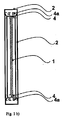
図1a)は、金属/プラスチックフレーム2に確実に装着された金属製温度制御板1で製作された本発明の濾板の平面図である。導入すべき懸濁液は、コーナー入口3を介して濾過室に送入され、濾液は濾液排出路4を介して排出される。濾液排出路4は、波形要素の凹所として形成されると共に、孔4aを介して濾液流出口5に接続される。温度制御媒体が、管ニップル6を介して供給及び排出される。破線に沿った仮想断面が描かれている。以下の図は、濾板の矢印AとBの方向に見た想像断面を示す。
(Example)
FIG. 1 a) is a plan view of a filter plate according to the invention made with a metal
図1b)は、図1a)に示す濾板の想像断面の平面図である。フレーム2内の温度制御板1は、その両側の全周に排出路4を備え、排出路4は、孔4aを介して濾液流出口5に接続される。
FIG. 1b) is a plan view of an imaginary cross section of the filter plate shown in FIG. 1a). The
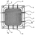
図2は、金属/プラスチックフレーム2に確実に装着された金属製温度制御板1で製作された本発明の濾板の平面図を示す。導入すべき懸濁液は、中央入口3を介して濾過室に送入され、濾液は排出路4を介して排出される。排出路4は、波形要素との接触面においてフレーム2に形成されると共に、孔4aを介して濾液流出口5に接続される。温度制御媒体が、管ニップル6を介して供給及び排出される。支持突起7が濾過室を安定化する。
FIG. 2 shows a plan view of a filter plate according to the invention made of a metal
図3a)は、金属/プラスチックフレーム2に不確実に装着された金属製温度制御板1で製作された本発明の濾板の平面図である。導入すべき懸濁液は、コーナー入口3を介して濾過室に送入され、濾液は孔4aを介して排出される。孔4aは、フレーム2と温度制御板1の間の中間空間を濾液流出口5に接続する。温度制御媒体が、管ニップル6を介して供給及び排出される。温度制御板1とフレーム2は、スタッド及び/又はボルト7を介して互いに接続される。破線に沿った仮想断面が描かれている。以下の図は、矢印AとBの方向に見た想像断面を示す。
FIG. 3 a) is a plan view of a filter plate according to the invention made with a metal
図3b)は、図3a)に示す濾板の想像断面の平面図である。フレーム2は、フレーム2と温度制御板1の間の中間空間を濾液流出口5に接続する孔4aを備える。
FIG. 3b) is a plan view of an imaginary cross section of the filter plate shown in FIG. 3a). The
図4は、金属/プラスチックフレーム2に不確実に装着された金属製温度制御板1で製作された本発明の濾板の平面図を示す。導入すべき懸濁液は、中央入口3を介して濾過室に送入され、濾液は孔4aを介して排出される。孔4aは、フレーム2と温度制御板1の間の中間空間を濾液流出口5に接続する。温度制御媒体が、管ニップル6を介して供給及び排出される。支持突起8が濾過室を安定化する。温度制御板1とフレーム2は、スタッド及び/又はボルト7を介して互いに接続される。
FIG. 4 shows a plan view of a filter plate according to the invention made of a metal
図5は、破線に沿って仮想切断される、フレームを消去した温度制御板の平面図を示す。以下の図は、温度制御板の矢印Aの方向に見た想像断面を示す。 FIG. 5 shows a plan view of the temperature control plate virtually erased along the broken line and with the frame removed. The following figure shows an imaginary cross section viewed in the direction of arrow A on the temperature control plate.
図6は、図5に示す温度制御板の想像断面の平面図を示す。温度制御板は、互いに90°だけ偏倚して配置した2枚の波形薄板から成る。下方薄板1は波形縁部として見える一方、上方薄板2は、側面図の最外方の波を示す。薄板は、外縁部及び接触点において溶接又ははんだ付けにより互いに接続される。
FIG. 6 shows a plan view of an imaginary cross section of the temperature control plate shown in FIG. The temperature control plate consists of two corrugated thin plates that are offset by 90 ° from each other. The
図7は、図5に示す温度制御板の想像断面の平面図を示す。温度制御板は、互いに90°だけ偏倚して配置した3枚の波形薄板から成る。底部薄板1と頂部薄板3は、夫々、波形縁部として見える一方、中間薄板2は、側面図の最外方の波を示す。薄板は、外縁部及び接触点において溶接又ははんだ付けにより互いに接続される。
FIG. 7 shows a plan view of an imaginary cross section of the temperature control plate shown in FIG. The temperature control plate is composed of three corrugated thin plates that are offset from each other by 90 °. The
図8は、乾燥時間に対するフィルターケーキ温度の変化を示す。実験A、BとCでは、金属製加熱冷却部材を有する本発明の濾板とポリプロピレンのダイアフラム室濾板を備える本発明のフィルタープレスにおいて、本発明の方法により、無機固体が濾過及び乾燥される。3個の全ての実験における金属製加熱冷却部材に対する温度制御媒体温度は100℃に達する一方、ダイアフラム室板に対する圧力媒体は、実験Aでは80℃であるが実験BとCでは僅か60℃である。3個の全ての実験で、真空ポンプにおいて測定して40ミリバールの低圧が印加される。実験Cの場合だけ、濾板の加熱冷却部材は、プレス作業開始時に既に加熱されている一方、実験AとBでは、加熱開始はプレス作業後まで生じない。3個の全ての実験において、圧力媒体は、プレス作業ステップ後まで加熱されない。実験AとBでは、最初の約15分の経過後に、約38℃の冷却限界温度へのフィルターケーキ温度の遅い増加が観測され、この時、冷却限界温度は、約40分静止して、更に25分経過後に約80℃に上昇する前に、残留濾液がフィルターケーキから蒸発する。実験Cでは、プレス作業ステップの開始時に加熱を開始することにより、約55℃のより高い初期温度が観測され、この初期温度は、最初の15分の経過後に約45℃にゆっくりと低下し、次の15分の経過後に80℃に増加し、更に20分後に100℃に達する。この場合、冷却限界温度の静止は観測されない。 FIG. 8 shows the change in filter cake temperature with respect to drying time. In Experiments A, B and C, inorganic solids are filtered and dried by the method of the present invention in the filter press of the present invention having the filter plate of the present invention having a metal heating and cooling member and the polypropylene diaphragm chamber filter plate. . The temperature control medium temperature for the metal heating and cooling members in all three experiments reaches 100 ° C., while the pressure medium for the diaphragm chamber plate is 80 ° C. in experiment A but only 60 ° C. in experiments B and C. . In all three experiments, a low pressure of 40 mbar, as measured in a vacuum pump, is applied. Only in the case of Experiment C, the heating and cooling member of the filter plate is already heated at the start of the pressing operation, whereas in Experiments A and B, the heating start does not occur until after the pressing operation. In all three experiments, the pressure medium is not heated until after the pressing step. In Experiments A and B, a slow increase in filter cake temperature to a cooling limit temperature of about 38 ° C. was observed after the first about 15 minutes, at which time the cooling limit temperature remained stationary for about 40 minutes, The residual filtrate evaporates from the filter cake before rising to about 80 ° C. after 25 minutes. In Experiment C, by starting heating at the beginning of the press work step, a higher initial temperature of about 55 ° C. is observed, which slowly decreases to about 45 ° C. after the first 15 minutes, It increases to 80 ° C after the next 15 minutes and reaches 100 ° C after another 20 minutes. In this case, stillness of the cooling limit temperature is not observed.
図9は、1個の加熱加圧回路を有するダイアフラム室フィルタープレスとダイアフラムフレーム・フィルタープレスの流れ図を示す。ダイアフラム室濾板9と濾板又は連係フレーム付き加圧/洗浄板10が、スタンド17に交互に配置されている。接続部18を介して、ダイアフラム室フィルタープレスは懸濁液で充填される。ギャップ洗浄の場合、洗浄液も接続部18を介して供給され、濾液流路洗浄の場合、これは接続部19を介して行われる。濾液は濾液出口20から排出される。
FIG. 9 shows a flow diagram of a diaphragm chamber filter press and a diaphragm frame filter press with one heating and pressing circuit. The diaphragm chamber filter plate 9 and the pressure plate /
ダイアフラム室濾板9と濾板又は連係フレーム付き加圧/洗浄板10は、レシーバ13、熱交換器11と搬送加圧ポンプ12から成る加熱加圧回路を形成する。この回路により、フィルターケーキをプレスすることができる。乾燥位相中、循環液体は熱交換器11により加熱される。同時に、濾液出口20が閉鎖されると共に、不活性材料が、凝縮器14における凝縮とセパレータ15における分離の後に真空ポンプ16から排出される。
The diaphragm chamber filter plate 9 and the pressurizing /
図10は、2個の加熱加圧回路を有するダイアフラム室フィルタープレスとダイアフラムフレーム・フィルタープレスの流れ図を示す。図9と異なり、ダイアフラム室濾板と濾板又は連係フレーム付き加圧/洗浄板は別個の加熱回路を有する(濾板又は連係フレーム付き加圧/洗浄板10は、熱交換器11、加圧ポンプ12とレシーバ13を有する一方、ダイアフラム室濾板9は、熱交換器21、加圧ポンプ22とレシーバ23を有する)。この構成の利点は、異なる温度を回路に設定できることである。その上に、ここで、回路を、プレス位相の開始時でも高温で濾板又は連係フレーム付き加圧/洗浄板を介して接続できる。
FIG. 10 shows a flow diagram of a diaphragm chamber filter press and a diaphragm frame filter press having two heating and pressing circuits. Unlike FIG. 9, the diaphragm chamber filter plate and the pressure plate / washing plate with the linkage frame or the linkage frame have separate heating circuits (the pressure plate /
図11は、濾板用加熱回路とダイアフラム室濾板用プレス水接続を有する、ダイアフラム室フィルタープレスとダイアフラムフレーム・フィルタープレスの流れ図を示す。図9及び図10と異なり、ここでは、熱を、乾燥のために、濾板又は連係フレーム付き加圧/洗浄板10のみを介してフィルタープレスに導入することができる。濾板又は連係フレーム付き加圧/洗浄板10への良好な熱伝導と、例えば、PP(ポリプロピレン)に対して許容されるより高温の設定可能性とにより、乾燥位相は、延長されないか、又は、僅かしか延長されない。大きな利点は、従来のプレス水系統を有する既存のフィルタープレスを加圧ポンプ24とレシーバ25で容易にレトロフィットすることができる点である。
FIG. 11 shows a flow diagram of a diaphragm chamber filter press and diaphragm frame filter press having a filter plate heating circuit and a diaphragm chamber filter plate press water connection. Unlike FIGS. 9 and 10, here heat can be introduced into the filter press via the filter plate or pressure /
1 温度制御板
2 フレーム
3 コーナー入口
4 濾液排出路
5 濾液流出口
9 ダイアフラム室濾板
10 濾板又は加圧/洗浄板
11 熱交換器
12 搬送加圧ポンプ
13 レシーバ
14 凝縮器
15 セパレータ
16 真空ポンプ
DESCRIPTION OF
Claims (1)
温度制御媒体が、加熱冷却部材(1)を加熱又は冷却するように、第1ニップル(6)から第2ニップル(6)まで貫流できる少なくとも1個の空隙を形成する少なくとも2個の互いに連結された波形要素が、加熱冷却部材(1)として使用され、
加熱冷却部材(1)が、スタッド及び/又はボルト(7)を介してフレーム(2)に接続されることにより、中間空間が、加熱冷却部材(1)とフレーム(2)の間に形成され、濾過すべき懸濁液を入口(3)から濾過室に導入することにより、濾液が中間空間を介して出口(5)から排出される濾板。 A frame (2) having an inlet (3), an outlet (5), a first nipple (6), and a second nipple (6), and a heating / cooling member (1), are used for a diaphragm type filter press. With a temperature-controllable filter plate,
Temperature control medium, so as to heat or cool the heating and cooling element (1), at least two coupled together to form at least one air gap can flow from the first nipple (6) to the second nipple (6) Corrugated element is used as heating and cooling member (1) ,
The heating / cooling member (1) is connected to the frame (2) via studs and / or bolts (7) , so that an intermediate space is formed between the heating / cooling member (1) and the frame (2). by introducing the filtering chamber of the suspension to be filtered from the inlet (3), the filtrate is Ru are discharged from the outlet (5) via an intermediate space filter plates.
Applications Claiming Priority (3)
| Application Number | Priority Date | Filing Date | Title |
|---|---|---|---|
| DE102005008664.0 | 2005-02-25 | ||
| DE102005008664A DE102005008664A1 (en) | 2005-02-25 | 2005-02-25 | Tempered chamber filter plate or pressing-washing plate, for use in filter press, especially for drying filter cakes, has heating or cooling body with corrugated elements forming cavity for tempering medium |
| PCT/EP2006/001323 WO2006089662A1 (en) | 2005-02-25 | 2006-02-14 | Device and method for thermally drying filter cakes in diaphragm-filter presses |
Publications (3)
| Publication Number | Publication Date |
|---|---|
| JP2008531251A JP2008531251A (en) | 2008-08-14 |
| JP2008531251A5 JP2008531251A5 (en) | 2009-02-19 |
| JP5329096B2 true JP5329096B2 (en) | 2013-10-30 |
Family
ID=36097312
Family Applications (1)
| Application Number | Title | Priority Date | Filing Date |
|---|---|---|---|
| JP2007556525A Expired - Fee Related JP5329096B2 (en) | 2005-02-25 | 2006-02-14 | Apparatus and method for thermally drying filter cake of diaphragm chamber filter press |
Country Status (10)
| Country | Link |
|---|---|
| US (1) | US20080277330A1 (en) |
| EP (1) | EP1858614B1 (en) |
| JP (1) | JP5329096B2 (en) |
| CN (1) | CN101128245B (en) |
| AT (1) | ATE471191T1 (en) |
| AU (1) | AU2006218183B2 (en) |
| CA (1) | CA2601942A1 (en) |
| DE (2) | DE102005008664A1 (en) |
| WO (1) | WO2006089662A1 (en) |
| ZA (1) | ZA200706999B (en) |
Families Citing this family (7)
| Publication number | Priority date | Publication date | Assignee | Title |
|---|---|---|---|---|
| CA2662770C (en) * | 2008-09-25 | 2016-10-25 | Metawater Co., Ltd. | Filtering and condensing apparatus of suction type |
| DE202009014692U1 (en) | 2009-10-30 | 2011-03-17 | Jvk Filtration Systems Gmbh | Filter plate with tempering and filter pack with such a filter plate |
| CN105327534B (en) * | 2014-08-13 | 2017-05-24 | 吕明旺 | Composite plate-frame type drying filter press |
| CN104606932A (en) * | 2015-01-30 | 2015-05-13 | 河南百汇环境工程有限公司 | Filter plate structure of variable-capacity type filter press |
| DE102017221347A1 (en) * | 2017-11-28 | 2019-05-29 | Thyssenkrupp Ag | Hybrid component with temperature control room |
| CN110354549B (en) * | 2019-08-01 | 2023-05-26 | 景津装备股份有限公司 | Van-type stainless steel comprehensive heating filter plate |
| CN113233733A (en) * | 2020-12-31 | 2021-08-10 | 第一环保(深圳)股份有限公司 | Electromagnetic heating plate for magnetic-thermal diaphragm airflow sludge dewatering and drying integrated equipment |
Family Cites Families (19)
| Publication number | Priority date | Publication date | Assignee | Title |
|---|---|---|---|---|
| CH249114A (en) * | 1946-01-26 | 1947-06-15 | Koehler Bosshardt & Co | Filter plate for filter presses. |
| DE2358578C3 (en) * | 1973-11-24 | 1980-01-24 | Lenser Kunststoff-Presswerk Gmbh + Co Kg, 7913 Senden | Filter plate for a filter press |
| DE2733769A1 (en) * | 1977-07-27 | 1979-02-15 | Lenser Kunststoff Press | FILTER PLATE |
| US4454044A (en) * | 1981-07-13 | 1984-06-12 | Max Klein | Water treatment process |
| JPS5861811A (en) * | 1981-10-09 | 1983-04-13 | Kurita Mach Mfg Co Ltd | Squeezing plate of filter press |
| GB2134808B (en) * | 1983-01-24 | 1987-08-05 | English Clays Lovering Pochin | Pressure filters |
| US4495071A (en) * | 1983-03-24 | 1985-01-22 | John R. Schneider | Horizontal plate filter with self-aligning plates |
| FR2585264B1 (en) * | 1985-06-04 | 1990-03-23 | Parmentier Alfred H | PRESS FILTERS |
| GB8530893D0 (en) * | 1985-12-16 | 1986-01-29 | Ici Plc | Electrode |
| GB2189403B (en) * | 1986-04-21 | 1989-11-29 | Steetley Refractories Ltd | Method of and apparatus for filtering a slurry |
| DE3819047A1 (en) * | 1988-06-04 | 1988-12-29 | Witzenmann Metallschlauchfab | Plate for filter presses |
| DE3943259A1 (en) * | 1989-12-29 | 1991-07-04 | Rittershaus & Blecher Gmbh | MEMBRANE PLATE FOR FILTER PRESSES |
| US6149806A (en) * | 1995-05-12 | 2000-11-21 | Baer; William | Two piece frame and two piece diaphragm filter plate |
| US5725767A (en) * | 1996-02-15 | 1998-03-10 | Calvest Associates, Inc. | Torsion resistant filter structure |
| US5651889A (en) * | 1996-03-25 | 1997-07-29 | Mitsui Petrochemical Industries, Ltd. | Sludge treatment membrane apparatus |
| US6180002B1 (en) * | 1998-08-03 | 2001-01-30 | United States Filter Corporation | Filter press with alternating diaphragm squeeze chamber plates and filtration chamber plates |
| CN2386868Y (en) * | 1999-06-21 | 2000-07-12 | 王艳霞 | Liquid filtering appts. of plate frame pressure filter |
| DE20006891U1 (en) * | 2000-04-14 | 2000-07-27 | Buhl Rolf F | Heating element for a filter press |
| CN2417915Y (en) * | 2000-04-14 | 2001-02-07 | 朱兴源 | Inlaid diaphragm filtering plate |
-
2005
- 2005-02-25 DE DE102005008664A patent/DE102005008664A1/en not_active Withdrawn
-
2006
- 2006-02-14 CN CN2006800059615A patent/CN101128245B/en not_active Expired - Fee Related
- 2006-02-14 JP JP2007556525A patent/JP5329096B2/en not_active Expired - Fee Related
- 2006-02-14 EP EP06706930A patent/EP1858614B1/en not_active Not-in-force
- 2006-02-14 AU AU2006218183A patent/AU2006218183B2/en not_active Ceased
- 2006-02-14 US US11/816,503 patent/US20080277330A1/en not_active Abandoned
- 2006-02-14 WO PCT/EP2006/001323 patent/WO2006089662A1/en active Application Filing
- 2006-02-14 DE DE502006007228T patent/DE502006007228D1/en active Active
- 2006-02-14 CA CA002601942A patent/CA2601942A1/en not_active Abandoned
- 2006-02-14 AT AT06706930T patent/ATE471191T1/en active
-
2007
- 2007-08-21 ZA ZA200706999A patent/ZA200706999B/en unknown
Also Published As
| Publication number | Publication date |
|---|---|
| ZA200706999B (en) | 2009-11-25 |
| DE102005008664A1 (en) | 2006-08-31 |
| CA2601942A1 (en) | 2006-08-31 |
| CN101128245A (en) | 2008-02-20 |
| JP2008531251A (en) | 2008-08-14 |
| EP1858614A1 (en) | 2007-11-28 |
| ATE471191T1 (en) | 2010-07-15 |
| AU2006218183A2 (en) | 2006-08-31 |
| WO2006089662A1 (en) | 2006-08-31 |
| US20080277330A1 (en) | 2008-11-13 |
| AU2006218183A1 (en) | 2006-08-31 |
| EP1858614B1 (en) | 2010-06-16 |
| CN101128245B (en) | 2011-02-23 |
| DE502006007228D1 (en) | 2010-07-29 |
| AU2006218183B2 (en) | 2011-05-26 |
Similar Documents
| Publication | Publication Date | Title |
|---|---|---|
| JP5329096B2 (en) | Apparatus and method for thermally drying filter cake of diaphragm chamber filter press | |
| US7736502B2 (en) | Temperature transfer filter plate assembly | |
| EP0978304A2 (en) | Filter press with alternating diaphragm squeeze chamber plates and filtration chamber plates | |
| US6387282B1 (en) | Method of drying a filter cake and a press for carrying out the method | |
| US5198123A (en) | Plate filter press | |
| WO2008031401A3 (en) | Method and device for dewatering and drying solid or liquid mixtures | |
| US20060032805A1 (en) | Heating plate for vacuum filter press | |
| CN207984049U (en) | A kind of quick fuel-displaced hydraulic oil press | |
| JP4127221B2 (en) | Heated filter press | |
| EP1687076A1 (en) | Filter presses | |
| JP3815944B2 (en) | Sludge dehydration drying method | |
| ES2209308T3 (en) | DRYING PROCEDURE OF FILTRATION CAKES FORMED IN FILTER CAMERAS OF A FILTER-PRESS, AS WELL AS FILTER-PRESS TO CARRY OUT THE PROCEDURE. | |
| JP3773164B2 (en) | Filter press device, filter plate for filter press device, and sludge dewatering method | |
| JP3773192B2 (en) | Sludge dewatering method | |
| JP3739049B2 (en) | Filter press filter plate | |
| JP2005270828A (en) | Method for dewatering slurry and filter press | |
| JP2004082036A (en) | Heating type filter press | |
| JP3773193B2 (en) | Filter press apparatus and sludge dewatering method | |
| JP2004361006A (en) | Dehydrating and drying apparatus and method | |
| CN210205949U (en) | Efficient heat transfer filtering chassis structure | |
| JP2004358356A (en) | Dehydrating and drying apparatus and method | |
| JP3812908B2 (en) | Cryptosporidium inactivation method and water treatment equipment in water treatment | |
| KR20220001586A (en) | plate for plate and frame type filter press | |
| JP2001129317A (en) | Filtration apparatus and filtration method | |
| CN116214801A (en) | Beeswax condensation forming machine |
Legal Events
| Date | Code | Title | Description |
|---|---|---|---|
| A521 | Request for written amendment filed |
Free format text: JAPANESE INTERMEDIATE CODE: A523 Effective date: 20081226 |
|
| A621 | Written request for application examination |
Free format text: JAPANESE INTERMEDIATE CODE: A621 Effective date: 20081226 |
|
| A131 | Notification of reasons for refusal |
Free format text: JAPANESE INTERMEDIATE CODE: A131 Effective date: 20120131 |
|
| A521 | Request for written amendment filed |
Free format text: JAPANESE INTERMEDIATE CODE: A523 Effective date: 20120426 |
|
| A131 | Notification of reasons for refusal |
Free format text: JAPANESE INTERMEDIATE CODE: A131 Effective date: 20120807 |
|
| A521 | Request for written amendment filed |
Free format text: JAPANESE INTERMEDIATE CODE: A523 Effective date: 20121019 |
|
| A711 | Notification of change in applicant |
Free format text: JAPANESE INTERMEDIATE CODE: A711 Effective date: 20121207 |
|
| TRDD | Decision of grant or rejection written | ||
| A01 | Written decision to grant a patent or to grant a registration (utility model) |
Free format text: JAPANESE INTERMEDIATE CODE: A01 Effective date: 20130625 |
|
| A61 | First payment of annual fees (during grant procedure) |
Free format text: JAPANESE INTERMEDIATE CODE: A61 Effective date: 20130724 |
|
| R150 | Certificate of patent or registration of utility model |
Free format text: JAPANESE INTERMEDIATE CODE: R150 |
|
| LAPS | Cancellation because of no payment of annual fees |