JP5328295B2 - Fuel cell system and method for stopping fuel cell system - Google Patents
Fuel cell system and method for stopping fuel cell system Download PDFInfo
- Publication number
- JP5328295B2 JP5328295B2 JP2008279726A JP2008279726A JP5328295B2 JP 5328295 B2 JP5328295 B2 JP 5328295B2 JP 2008279726 A JP2008279726 A JP 2008279726A JP 2008279726 A JP2008279726 A JP 2008279726A JP 5328295 B2 JP5328295 B2 JP 5328295B2
- Authority
- JP
- Japan
- Prior art keywords
- fuel cell
- scavenging
- back pressure
- pressure valve
- generated water
- Prior art date
- Legal status (The legal status is an assumption and is not a legal conclusion. Google has not performed a legal analysis and makes no representation as to the accuracy of the status listed.)
- Expired - Fee Related
Links
- 239000000446 fuel Substances 0.000 title claims abstract description 213
- 238000000034 method Methods 0.000 title claims abstract description 39
- 230000002000 scavenging effect Effects 0.000 claims abstract description 113
- XLYOFNOQVPJJNP-UHFFFAOYSA-N water Substances O XLYOFNOQVPJJNP-UHFFFAOYSA-N 0.000 claims abstract description 58
- 238000007710 freezing Methods 0.000 claims abstract description 51
- 230000008014 freezing Effects 0.000 claims abstract description 48
- 238000010248 power generation Methods 0.000 claims abstract description 10
- 238000001514 detection method Methods 0.000 claims description 30
- 230000005611 electricity Effects 0.000 claims description 4
- 230000002265 prevention Effects 0.000 claims description 2
- 239000000376 reactant Substances 0.000 abstract 9
- 239000007789 gas Substances 0.000 description 63
- UFHFLCQGNIYNRP-UHFFFAOYSA-N Hydrogen Chemical compound [H][H] UFHFLCQGNIYNRP-UHFFFAOYSA-N 0.000 description 11
- 238000010926 purge Methods 0.000 description 9
- 239000001257 hydrogen Substances 0.000 description 7
- 229910052739 hydrogen Inorganic materials 0.000 description 7
- 239000012495 reaction gas Substances 0.000 description 6
- 238000004891 communication Methods 0.000 description 5
- 230000004913 activation Effects 0.000 description 4
- 238000010586 diagram Methods 0.000 description 4
- 239000012528 membrane Substances 0.000 description 4
- 238000011144 upstream manufacturing Methods 0.000 description 4
- 230000006378 damage Effects 0.000 description 3
- 239000007787 solid Substances 0.000 description 3
- 238000010790 dilution Methods 0.000 description 2
- 239000012895 dilution Substances 0.000 description 2
- 238000003487 electrochemical reaction Methods 0.000 description 2
- 230000007257 malfunction Effects 0.000 description 2
- 239000007800 oxidant agent Substances 0.000 description 2
- 239000001301 oxygen Substances 0.000 description 2
- 229910052760 oxygen Inorganic materials 0.000 description 2
- 239000005518 polymer electrolyte Substances 0.000 description 2
- 230000005856 abnormality Effects 0.000 description 1
- QVGXLLKOCUKJST-UHFFFAOYSA-N atomic oxygen Chemical compound [O] QVGXLLKOCUKJST-UHFFFAOYSA-N 0.000 description 1
- 238000006555 catalytic reaction Methods 0.000 description 1
- 230000000694 effects Effects 0.000 description 1
- 239000002737 fuel gas Substances 0.000 description 1
- -1 hydrogen ions Chemical class 0.000 description 1
- 238000012986 modification Methods 0.000 description 1
- 230000004048 modification Effects 0.000 description 1
- 230000001590 oxidative effect Effects 0.000 description 1
- 150000002926 oxygen Chemical class 0.000 description 1
- 230000002093 peripheral effect Effects 0.000 description 1
- 229920005597 polymer membrane Polymers 0.000 description 1
- 239000003507 refrigerant Substances 0.000 description 1
Images


Classifications
-
- Y—GENERAL TAGGING OF NEW TECHNOLOGICAL DEVELOPMENTS; GENERAL TAGGING OF CROSS-SECTIONAL TECHNOLOGIES SPANNING OVER SEVERAL SECTIONS OF THE IPC; TECHNICAL SUBJECTS COVERED BY FORMER USPC CROSS-REFERENCE ART COLLECTIONS [XRACs] AND DIGESTS
- Y02—TECHNOLOGIES OR APPLICATIONS FOR MITIGATION OR ADAPTATION AGAINST CLIMATE CHANGE
- Y02E—REDUCTION OF GREENHOUSE GAS [GHG] EMISSIONS, RELATED TO ENERGY GENERATION, TRANSMISSION OR DISTRIBUTION
- Y02E60/00—Enabling technologies; Technologies with a potential or indirect contribution to GHG emissions mitigation
- Y02E60/30—Hydrogen technology
- Y02E60/50—Fuel cells
Landscapes
- Fuel Cell (AREA)
Abstract
Description
本発明は、燃料電池システムおよび燃料電池システムの停止方法に関するものである。 The present invention relates to a fuel cell system and a method for stopping the fuel cell system.
従来から、例えば車両に搭載される燃料電池には、固体高分子電解質膜をアノード電極およびカソード電極で両側から挟んで膜電極構造体を形成し、この膜電極構造体の両側に一対のセパレータを配置して平板状の単位燃料電池(以下、単位セルという。)を構成し、この単位セルを複数積層して燃料電池スタック(以下、燃料電池という。)とするものが知られている。このような燃料電池では、アノード電極とセパレータとの間にアノードガス(燃料ガス)として水素ガスを供給するとともに、カソード電極とセパレータとの間にカソードガス(酸化剤ガス)として空気を供給する。これにより、アノード電極で触媒反応により発生した水素イオンが、固体高分子電解質膜を透過してカソード電極まで移動し、カソード電極で空気中の酸素と電気化学反応を起こし、発電が行われる。なお、この発電に伴って、燃料電池内部で水が生成される。 Conventionally, for example, in a fuel cell mounted on a vehicle, a membrane electrode structure is formed by sandwiching a solid polymer electrolyte membrane between an anode electrode and a cathode electrode from both sides, and a pair of separators are provided on both sides of the membrane electrode structure. A flat unit fuel cell (hereinafter referred to as a unit cell) is arranged to form a fuel cell stack (hereinafter referred to as a fuel cell) by stacking a plurality of unit cells. In such a fuel cell, hydrogen gas is supplied as an anode gas (fuel gas) between the anode electrode and the separator, and air is supplied as a cathode gas (oxidant gas) between the cathode electrode and the separator. As a result, hydrogen ions generated by the catalytic reaction at the anode electrode pass through the solid polymer electrolyte membrane and move to the cathode electrode, causing an electrochemical reaction with oxygen in the air at the cathode electrode, thereby generating power. It should be noted that water is generated inside the fuel cell with this power generation.
このような燃料電池を備える燃料電池システムでは、例えば氷点下環境で使用されると、燃料電池システムの停止中に内部に残留している生成水が凍結してしまうため、生成水が凍結した場合に燃料電池システムの起動を禁止する技術が開示されている(例えば、特許文献1参照)。
この特許文献1の燃料電池システムは、燃料電池システムの起動操作が行われたら、シャットバルブを開くとともに、温度センサにより温度を測定する。測定された温度が所定値以下の場合には、圧力センサにより圧力値が正常であるか否かを判定し、正常である場合は排出バルブを開き、圧力センサにより測定される圧力低下量が正常であるか否かを判定する。次に、排出バルブを閉じ、圧力センサにより測定される圧力上昇量が正常であるか否かを判定する。次に、水素ポンプを起動し、回転数が正常であるかを判定する。次に、コンプレッサを作動し、圧力センサにより測定される圧力値が正常であるか否かを判定する。以上の判定において、一つでも異常があれば、凍結している部品が存在すると判断して、燃料電池システムの起動を禁止するものである。
In the fuel cell system of Patent Document 1, when a start operation of the fuel cell system is performed, the shut valve is opened and the temperature is measured by a temperature sensor. If the measured temperature is less than the predetermined value, the pressure sensor determines whether the pressure value is normal. If it is normal, the discharge valve is opened and the pressure drop measured by the pressure sensor is normal. It is determined whether or not. Next, the discharge valve is closed, and it is determined whether or not the amount of pressure increase measured by the pressure sensor is normal. Next, the hydrogen pump is started and it is determined whether the rotation speed is normal. Next, the compressor is operated, and it is determined whether or not the pressure value measured by the pressure sensor is normal. In the above determination, if there is any abnormality, it is determined that there are frozen parts, and the activation of the fuel cell system is prohibited.
ところで、特許文献1の燃料電池システムでは、上述したように凍結している部品がある場合には燃料電池システムの起動を禁止するものであるが、このような氷点下環境下においても燃料電池システムを使用できる技術が望まれている。
また、燃料電池システムには、燃料電池システムの停止中に内部に残留している生成水が凍結してしまうため、生成水が凍結しないように燃料電池システム内に付着した水滴を除去(掃気)する方法が開示されている。しかしながら、従来の燃料電池システムの掃気方法では、燃料電池の温度に応じて掃気を行うか否かを判定しているため、例えば、燃料電池システムを短時間起動して、燃料電池は暖機されたが、バルブ類などは暖機されない場合は掃気が行われないことになる。そのため、生成水がバルブ類などに付着して凍結し、燃料電池システムの次回起動時に正常に起動できなくなる虞がある。
By the way, in the fuel cell system of Patent Document 1, the start of the fuel cell system is prohibited when there are frozen parts as described above. However, even in such a sub-freezing environment, the fuel cell system is A technique that can be used is desired.
Further, in the fuel cell system, the generated water remaining inside the fuel cell system is frozen while the fuel cell system is stopped, so that water droplets adhering to the fuel cell system are removed so that the generated water does not freeze (scavenging). A method is disclosed. However, since the conventional scavenging method for a fuel cell system determines whether or not scavenging is performed according to the temperature of the fuel cell, for example, the fuel cell is warmed up by starting the fuel cell system for a short time. However, scavenging is not performed when the valves are not warmed up. For this reason, the generated water adheres to the valves and freezes, and there is a possibility that the fuel cell system cannot be normally started when the fuel cell system is next started.
そこで、本発明は、上記事情を鑑みてなされたものであり、氷点下環境下において燃料電池システムを確実に起動することができる燃料電池システムおよび燃料電池システムの掃気方法を提供するものである。 Accordingly, the present invention has been made in view of the above circumstances, and provides a fuel cell system and a scavenging method for the fuel cell system that can reliably start the fuel cell system in a sub-freezing environment.
上記の課題を解決するために、請求項1に記載した発明は、アノード電極にアノードガスを、カソード電極にカソードガスを供給し発電を行う燃料電池(例えば、実施形態における燃料電池11)と、前記燃料電池から排出された前記カソードガスが流通するカソードガス配管(例えば、実施形態におけるカソードオフガス排出配管38)と、該カソードガス配管に配され、前記カソードガスの流れを調整する背圧弁(例えば、実施形態における背圧弁34)と、を備えた燃料電池システム(例えば、実施形態における燃料電池システム10)であって、該背圧弁の温度を検出する温度検出手段(例えば、実施形態における温度センサ55)と、前記燃料電池の発電停止中に、前記背圧弁に付着した前記燃料電池の生成水の除去を行う掃気手段(例えば、実施形態におけるエアコンプレッサ33)と、前記温度検出手段の検出値に基づいて、前記背圧弁において前記生成水が凍結するか否かを判定する凍結判定手段(例えば、実施形態における背圧弁凍結判定部48)と、をさらに有し、該凍結判定手段により前記背圧弁で前記生成水が凍結する虞があると判定された際に、前記掃気手段による掃気を実行可能に構成され、前記燃料電池内部の前記生成水の凍結可否を判定する燃料電池内部凍結判定手段(例えば、実施形態における燃料電池内部凍結判定部50)を有し、前記背圧弁の掃気後に、前記燃料電池内部が凍結する虞があると判定された場合には、前記掃気手段により前記燃料電池内部の掃気を実行可能に構成され、前記掃気手段は、前記アノード電極および前記カソード電極の一方のみを掃気するか、両方を掃気するかを切替可能な切替手段(例えば、実施形態における電磁弁54)を備え、前記燃料電池内部が凍結する虞があると判定された場合には、前記切替手段は両方の電極を掃気できるように切り替えられ、前記燃料電池内部の掃気を実行可能に構成されていることを特徴としている。
In order to solve the above problems, the invention described in claim 1 is a fuel cell (for example, fuel cell 11 in the embodiment) that generates electricity by supplying an anode gas to an anode electrode and a cathode gas to a cathode electrode; A cathode gas pipe (for example, cathode
請求項2に記載した発明は、前記燃料電池の発電中に、該燃料電池で生成される生成水量を検出する生成水量検出手段(例えば、実施形態における生成水量検出部47)を有し、前記生成水量が所定量以下である場合には、前記反応ガス調整手段の掃気を実行しないことを特徴としている。
The invention described in claim 2 includes a generated water amount detecting means (for example, a generated water
請求項3に記載した発明は、前記掃気手段は蓄電装置により駆動され、該蓄電装置の残量が、前記反応ガス調整手段の掃気および前記燃料電池内部の掃気に費やす電力量合計以下となっている場合であって、前記燃料電池内部の掃気によって前記反応ガス調整手段も掃気できる場合には、前記反応ガス調整手段の掃気を取り止めて、前記燃料電池内部の掃気を実行可能に構成されていることを特徴としている。 According to a third aspect of the present invention, the scavenging means is driven by a power storage device, and the remaining amount of the power storage device is less than or equal to the total amount of power spent for scavenging the reaction gas adjusting means and scavenging inside the fuel cell. If the reaction gas adjustment means can also be scavenged by scavenging inside the fuel cell, scavenging of the reaction gas adjustment means is stopped and scavenging inside the fuel cell can be executed. It is characterized by that .
請求項4に記載した発明は、アノード電極にアノードガスを、カソード電極にカソードガスを供給し発電を行う燃料電池と、前記燃料電池から排出された前記カソードガスが流通するカソードガス配管と、該カソードガス配管に配され、前記カソードガスの流れを調整する背圧弁と、該背圧弁の温度を検出する温度検出手段と、前記燃料電池の発電停止中に、前記背圧弁に付着した前記燃料電池の生成水の除去を行う掃気手段と、前記温度検出手段の検出値に基づいて、前記背圧弁で前記生成水が凍結するか否かを判定する凍結判定手段と、を備え、該凍結判定手段により前記背圧弁で前記生成水が凍結する虞があると判定された際に、前記掃気手段による掃気を実行する燃料電池システムの停止方法であって、前記燃料電池の後流側に位置する前記背圧弁の温度を測定するデバイス温度測定ステップと、前記背圧弁の凍結防止のための掃気が必要か否かを判定するデバイス掃気判定ステップと、前記背圧弁を掃気するデバイス掃気ステップと、前記燃料電池内部の前記生成水の凍結可否を判定する燃料電池内部凍結判定ステップと、前記アノード電極および前記カソード電極の一方のみを掃気するか、両方を掃気するかを切替可能な切替手段を備え、前記燃料電池内部が凍結する虞があると判定された場合には、両方の電極を掃気できるように前記切替手段を切り替えて、前記燃料電池内部の掃気をする燃料電池内部掃気ステップと、有することを特徴としている。 The invention described in claim 4 is a fuel cell for generating electricity by supplying an anode gas to the anode electrode and a cathode gas to the cathode electrode, a cathode gas pipe through which the cathode gas discharged from the fuel cell flows, disposed in the cathode gas piping, a back pressure valve for adjusting the flow of the cathode gas, a temperature detection means for detecting the temperature of the back pressure valve, during the power generation stop of the fuel cell, the fuel cell attached to the back pressure valve Scavenging means for removing the generated water and freezing determining means for determining whether or not the generated water is frozen by the back pressure valve based on a detection value of the temperature detecting means, the freezing determining means wherein when said produced water is determined that there is a risk of freezing in back-pressure valve, a method of stopping a fuel cell system that performs the scavenging by the scavenging unit, located on the downstream side of the fuel cell by Wherein the device temperature measuring step of measuring the temperature of the back pressure valve, and a device scavenging determination step of determining whether scavenging is required whether for freeze prevention of the back pressure valve, and a device scavenging step of scavenging the back pressure valve that, A fuel cell internal freezing determination step for determining whether or not the generated water in the fuel cell can be frozen; and a switching unit capable of switching between scavenging only one of the anode electrode and the cathode electrode or scavenging both. And a fuel cell internal scavenging step for scavenging the fuel cell by switching the switching means so that both electrodes can be scavenged when it is determined that there is a risk of freezing inside the fuel cell. It is characterized by that.
請求項1に記載した発明によれば、背圧弁の温度を検出し、背圧弁が凍結する虞があると判定された場合には、燃料電池停止直後に背圧弁の掃気を行うため、背圧弁に付着した液滴を確実に除去することができる。また、このように背圧弁の温度に基づいて、背圧弁の掃気の有無を判定することにより、例えば、燃料電池の暖機が完了された状態において、背圧弁が凍結する虞があると判定された場合であっても、背圧弁に付着した液滴を確実に除去することができる。したがって、燃料電池システムの次回起動時に、背圧弁が凍結による動作不良になるのを防止できるため、燃料電池システムを確実に起動することができる。
また、燃料電池内部に残留した生成水により燃料電池内部が凍結するのを防止できるため、燃料電池内部で生成水が凍結することにより生じる内部破壊を防止することができる。
According to the invention described in claim 1, to detect the temperature of the back pressure valve, when the back-pressure valve is determined that there is a risk of freezing, in order to perform scavenging of the back pressure valve immediately after the fuel cell stops, the back pressure valve The droplets adhering to the can be removed reliably. Further, by determining whether or not the back pressure valve is scavenged based on the temperature of the back pressure valve in this manner, for example, it is determined that there is a possibility that the back pressure valve may freeze in a state where the warm-up of the fuel cell is completed. Even in this case, the droplets adhering to the back pressure valve can be reliably removed. Therefore, when the fuel cell system is started next time, the back pressure valve can be prevented from malfunctioning due to freezing, so that the fuel cell system can be reliably started.
In addition, since the inside of the fuel cell can be prevented from freezing due to the generated water remaining inside the fuel cell, internal destruction caused by freezing of the generated water inside the fuel cell can be prevented.
請求項2に記載した発明によれば、燃料電池システムが起動してから停止するまでの間に燃料電池で生成された生成水量が所定量以下の場合には、背圧弁に付着する生成水量も少ないため、背圧弁が凍結により動作不良になる可能性が低くなる。したがって、生成水量が少ない場合には背圧弁の掃気を実行しないようにすることで、背圧弁の掃気のためのエネルギを削減することができる。 According to the second aspect of the present invention, when the amount of water generated in the fuel cell between the start and stop of the fuel cell system is equal to or less than a predetermined amount, the amount of generated water adhering to the back pressure valve is also reduced. Therefore , it is less likely that the back pressure valve will malfunction due to freezing. Therefore, the energy for scavenging the back pressure valve can be reduced by not performing scavenging of the back pressure valve when the amount of generated water is small.
請求項3に記載した発明によれば、蓄電装置の残量が不足している場合であっても、背圧弁および燃料電池内部の掃気をまとめて行うことができるため、背圧弁および燃料電池内部において生成水が凍結して、燃料電池システムの発電が不可能になるのを防止することができる。 According to the invention described in claim 3, even when the remaining amount of the power storage device is insufficient, since it is possible to collectively back pressure valve and a fuel cell inside the scavenging, the internal back pressure valve and the fuel cell It is possible to prevent the generated water from freezing and making it impossible to generate power in the fuel cell system.
請求項4に記載した発明によれば、背圧弁の温度を検出し、背圧弁が凍結する虞があると判定された場合には、燃料電池停止直後に背圧弁の掃気を行うため、背圧弁に付着した液滴を確実に除去することができる。また、このように背圧弁の温度に基づいて、背圧弁の掃気の有無を判定することにより、例えば、燃料電池の暖機が完了された状態において、背圧弁が凍結する虞があると判定された場合であっても、背圧弁に付着した液滴を確実に除去することができる。したがって、燃料電池システムの次回起動時に、背圧弁が凍結による動作不良になるのを防止できるため、燃料電池システムを確実に起動することができる。
また、燃料電池内部に残留した生成水により燃料電池内部が凍結するのを防止できるため、燃料電池内部で生成水が凍結することにより生じる内部破壊を防止することができる。
According to the invention described in claim 4, to detect the temperature of the back pressure valve, when the back-pressure valve is determined that there is a risk of freezing, in order to perform scavenging of the back pressure valve immediately after the fuel cell stops, the back pressure valve The droplets adhering to the can be removed reliably. Further, by determining whether or not the back pressure valve is scavenged based on the temperature of the back pressure valve in this manner, for example, it is determined that there is a possibility that the back pressure valve may freeze in a state where the warm-up of the fuel cell is completed. Even in this case, the droplets adhering to the back pressure valve can be reliably removed. Therefore, when the fuel cell system is started next time, the back pressure valve can be prevented from malfunctioning due to freezing, so that the fuel cell system can be reliably started.
In addition, since the inside of the fuel cell can be prevented from freezing due to the generated water remaining inside the fuel cell, internal destruction caused by freezing of the generated water inside the fuel cell can be prevented.
(第一実施形態)
次に、本発明に係る燃料電池システムの第一実施形態を図1〜図3に基づいて説明する。なお、本実施形態では燃料電池システムを車両に搭載した場合の説明をする。
(燃料電池システム)
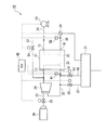
図1は燃料電池システムの概略構成図である。
図1に示すように、燃料電池システム10の燃料電池11は、水素ガスなどのアノードガスと空気などのカソードガスとの電気化学反応により発電を行う固体高分子膜型燃料電池である。燃料電池11に形成されたアノードガス供給用連通孔13(アノードガス流路21の入口側)にはアノードガス供給配管23が連結され、その上流端部には水素タンク30が接続されている。また、燃料電池11に形成されたカソードガス供給用連通孔15(カソードガス流路22の入口側)にはカソードガス供給配管24が連結され、その上流端部にはエアコンプレッサ33が接続されている。なお、燃料電池11に形成されたアノードオフガス排出用連通孔14(アノードガス流路21の出口側)にはアノードオフガス排出配管35が連結され、カソードオフガス排出用連通孔16(カソードガス流路22の出口側)にはカソードオフガス排出配管38が連結されている。
(First embodiment)
Next, a first embodiment of a fuel cell system according to the present invention will be described with reference to FIGS. In the present embodiment, a case where the fuel cell system is mounted on a vehicle will be described.
(Fuel cell system)
FIG. 1 is a schematic configuration diagram of a fuel cell system.
As shown in FIG. 1, the fuel cell 11 of the
また、水素タンク30からアノードガス供給配管23に供給された水素ガスは、レギュレータ(不図示)により減圧された後、エゼクタ26を通り、燃料電池11のアノードガス流路21に供給される。また、水素タンク30の下流側近傍には、電磁駆動式の電磁弁25が設けられており、水素タンク30からの水素ガスの供給を遮断することができるように構成されている。
Further, the hydrogen gas supplied from the
また、アノードオフガス排出配管35は、エゼクタ26に接続され、燃料電池11を通過してきたアノードオフガスを再度燃料電池11のアノードガスとして再利用できるように構成されている。さらに、アノードオフガス排出配管35は、途中で2本の配管が分岐して設けられており、一方はアノードエア排出配管36であり、他方はパージガス排出配管37である。アノードエア排出配管36およびパージガス排出配管37は、ともに希釈ボックス31に接続されている。そして、アノードエア排出配管36には電磁駆動式のアノードエア排出弁51が設けられており、パージガス排出配管37には電磁駆動式のパージ弁52が設けられている。なお、アノードエア排出配管36は、パージガス排出配管37よりも配管径の大きいものが取り付けられている。
The anode off-
次に、空気(カソードガス)はエアコンプレッサ33によって加圧され、カソードガス供給配管24を通過した後、燃料電池11のカソードガス流路22に供給される。この空気中の酸素が酸化剤として発電に供された後、燃料電池11からカソードオフガスとしてカソードオフガス排出配管38に排出される。カソードオフガス排出配管38は希釈ボックス31に接続され、その後、車外へと排気される。なお、カソードオフガス排出配管38には背圧弁34が設けられている。
ここで、背圧弁34の上流側(燃料電池11と背圧弁34との間)における背圧弁34の直近には温度センサ55が設けられている。温度センサ55により背圧弁34の温度と略同一の温度を検出することができるようになっている。温度センサ55からの検出結果(センサ出力)は、制御装置(ECU)45へ伝達され、その検出結果に基づいて、背圧弁34の掃気(後に詳述する。)を実行するか否かを決定するように構成されている。
Next, air (cathode gas) is pressurized by the air compressor 33, passes through the cathode
Here, a
また、エアコンプレッサ33と燃料電池11との間を繋ぐカソードガス供給配管24において、配管が分岐され掃気ガス導入配管53の一端が接続されている。掃気ガス導入配管53は、アノードガス供給配管23におけるエゼクタ26と燃料電池11との間に他端が接続されている。つまり、エアコンプレッサ33にて加圧された空気を燃料電池11のアノードガス流路21に供給できるようになっている。なお、掃気ガス導入配管53には電磁駆動式の電磁弁54が設けられており、エアコンプレッサ33からの空気の供給を遮断できるように構成されている。
Further, in the cathode
さらに、アノードオフガス排出配管35におけるアノードオフガス排出用連通孔14の直後(下流側)に、温度センサ41が設けられている。温度センサ41により、燃料電池11の内部の温度と略同一の温度を検知することができるようになっている。温度センサ41からの検出結果(センサ出力)は、制御装置(ECU)45へ伝達され、その検出結果に基づいて、燃料電池11内部の掃気(後に詳述する。)を実行するか否かを決定するように構成されている。
Further, a
図2は制御装置45の概略ブロック図である。図2に示すように、制御装置45は、燃料電池11で生成された生成水量を検出する生成水量検出部47と、温度センサ55の検出結果に基づいて背圧弁34が凍結する虞があるか否かを判定する背圧弁凍結判定部48と、燃料電池システム10が停止状態になってからの時間をカウントする停止時間検出部49と、停止時間検出部49でカウントしている時間が所定時間を経過したときに、温度センサ41の検出結果に基づいて燃料電池11内部が凍結する虞があるか否かを判定する燃料電池内部凍結判定部50と、を有している。
FIG. 2 is a schematic block diagram of the
さらに、制御装置45は、燃料電池11に要求される出力に応じて、電磁弁25を制御して水素タンク30から所定量の水素ガスを燃料電池11に供給することができるようになっている。また、制御装置45は、燃料電池11に要求される出力に応じて、エアコンプレッサ33を駆動して所定量の空気を燃料電池11に供給するとともに、背圧弁34を制御してカソードガス流路22への空気の供給圧力を調整できるように構成されている。
Further, the
そして、燃料電池内部凍結判定部50からの指示により燃料電池11内部などを掃気する際に、掃気ガス導入配管53の電磁弁54を制御して所定量の空気をアノード側にも供給することができるように構成されている。
Then, when scavenging the inside of the fuel cell 11 or the like according to an instruction from the fuel cell internal freezing
(燃料電池システムの停止方法)
次に、本実施形態における燃料電池システム10の停止方法について説明する。
図3は燃料電池システム10の停止方法を示すフローチャートである。
図3に示すように、ステップS11では、燃料電池システム10の起動信号であるイグニッションスイッチ(不図示)をオフにした後に、生成水量検出部47において、燃料電池11でイグニッションスイッチがオフされるまでの間に生成された生成水量を検出し、所定量以上の生成水が生成された場合にはステップS12へ進み、所定量未満の生成水しか生成されていない場合にはステップS15へ進む。例えば、生成水量は燃料電池11に設けた電流センサ(不図示)から検出される積算電流量に基づいて算出される。
(How to stop the fuel cell system)
Next, a method for stopping the
FIG. 3 is a flowchart showing a method for stopping the
As shown in FIG. 3, in step S <b> 11, after turning off an ignition switch (not shown) that is a start signal of the
ステップS12では、背圧弁34の温度を検出する。本実施形態では、背圧弁34の近傍に設けられた温度センサ55の検出結果を背圧弁34の温度と推定している。
In step S12, the temperature of the
ステップS13では、背圧弁凍結判定部48において、背圧弁34が凍結する虞があるか否かを温度センサ55の検出結果に応じて判定する。例えば、温度センサ55の検出温度が5℃以下である場合には、背圧弁34が凍結する虞があると判定する。背圧弁34が凍結する虞があると判定した場合にはステップS14へ進み、凍結する虞がないと判定した場合にはステップS15へ進む。
In step S <b> 13, the back pressure valve freezing
ステップS14では、背圧弁34の掃気を実行する。具体的には、掃気ガス導入配管53の電磁弁54を閉弁し、カソードオフガス排出配管38の背圧弁34を開弁する。そして、エアコンプレッサ33を駆動させることにより、加圧された空気をカソード側の配管に供給することで、背圧弁34の掃気を実行する。
In step S14, scavenging of the
ステップS15では、燃料電池内部凍結判定部50において、燃料電池11内部が凍結する虞があるか否かを温度センサ41の検出結果に応じて判定する。例えば、温度センサ41の検出温度が5℃以下である場合には、燃料電池11内部が凍結する虞があると判定する。燃料電池11内部が凍結する虞があると判定した場合にはステップS16へ進み、凍結する虞がないと判定した場合にはステップS17へ進む。
In step S <b> 15, the fuel cell internal freezing
ステップS16では、燃料電池11内部の掃気を実行する。具体的には、掃気ガス導入配管53の電磁弁54、アノードエア排出配管36のアノードエア排出弁51、パージガス排出配管37のパージ弁52およびカソードオフガス排出配管38の背圧弁34を開弁し、エアコンプレッサ33を駆動させることにより、加圧された空気をアノード側およびカソード側の配管などに供給することで、燃料電池11内部の掃気を実行する。燃料電池11内部の掃気が実行されると処理が終了する。
In step S16, scavenging inside the fuel cell 11 is executed. Specifically, the
ステップS17では、燃料電池システム10の起動信号であるイグニッションスイッチがオンされたか否かを判定し、いまだオフの状態であればステップS15へ戻り、イグニッションスイッチがオンされた場合には処理を終了する。なお、ステップS15〜S17は、例えば、停止時間検出部49で検出した停止時間により5分ごとに処理を実行するようにすればよい。
In step S17, it is determined whether or not the ignition switch that is the activation signal of the
なお、上述した背圧弁34の掃気および燃料電池11内部の掃気の際に必要な電力は、例えば燃料電池の電力を蓄電するバッテリ(不図示)から確保する。
Note that the electric power necessary for the above-described scavenging of the
本実施形態によれば、背圧弁34の温度を検出し、背圧弁34が凍結する虞があると判定された場合には、燃料電池11の発電停止直後に背圧弁34の掃気を行うため、背圧弁34に付着した液滴を確実に除去することができる。また、このように背圧弁34の温度に基づいて、背圧弁凍結判定部48で背圧弁34の掃気の必要有無を判定することにより、燃料電池11の暖機が完了された状態において、背圧弁34が凍結する虞があると判定された場合であっても、背圧弁34に付着した液滴を確実に除去することができる。したがって、燃料電池システム10の次回起動時に、背圧弁34が凍結による動作不良になるのを防止できるため、燃料電池システム10を確実に起動することができる。
According to the present embodiment, when the temperature of the
また、燃料電池システム10が起動してから停止するまでの間に燃料電池11で生成された生成水量が所定量以下の場合には、背圧弁34に付着する生成水量も少ないため、背圧弁34が凍結により動作不良になる可能性が低くなる。したがって、生成水量が少ない場合には背圧弁34の掃気を実行しないようにすることで、背圧弁34の掃気のためのエネルギを削減することができる。
In addition, when the amount of water generated by the fuel cell 11 between the start and stop of the
さらに、燃料電池内部凍結判定部50を設け、燃料電池11内部が凍結する虞があると判定した場合には、燃料電池11内部を掃気できるように構成したため、燃料電池11内部に残留した生成水により燃料電池11内部が凍結するのを防止できる。したがって、燃料電池11内部で生成水が凍結することにより生じる内部破壊を防止することができる。
Further, the fuel cell internal freezing
(第二実施形態)
次に、本発明に係る燃料電池システムの第二実施形態を図4〜図5に基づいて説明する。なお、本実施形態は第一実施形態と掃気の方法が異なるのみであり、燃料電池システムの構成は第一実施形態と略同一であるため、同一箇所には同一符号を付して詳細な説明は省略する。
(Second embodiment)
Next, a second embodiment of the fuel cell system according to the present invention will be described with reference to FIGS. The present embodiment is different from the first embodiment only in the scavenging method, and the configuration of the fuel cell system is substantially the same as that of the first embodiment. Is omitted.
(燃料電池システムの停止方法)
本実施形態における燃料電池システム10の停止方法について説明する。
図4は燃料電池システム10の停止方法を示すフローチャートである。
図4に示すように、ステップS21では、生成水量検出部47において、燃料電池11でイグニッションスイッチがオフされるまでの間に生成された生成水量を検出し、所定量以上の生成水が生成された場合にはステップS22へ進み、所定量未満の生成水しか生成されていない場合にはステップS26へ進む。
(How to stop the fuel cell system)
A method for stopping the
FIG. 4 is a flowchart showing a method for stopping the
As shown in FIG. 4, in step S <b> 21, the generated water
ステップS22では、背圧弁34の温度を検出する。本実施形態では、背圧弁34の近傍に設けられた温度センサ55の検出結果を背圧弁34の温度と推定している。
In step S22, the temperature of the
ステップS23では、背圧弁凍結判定部48において、背圧弁34が凍結する虞があるか否かを温度センサ55の検出結果に応じて判定する。例えば、温度センサ55の検出温度が5℃以下である場合には、背圧弁34が凍結する虞があると判定する。背圧弁34が凍結する虞があると判定した場合にはステップS24へ進み、凍結する虞がないと判定した場合にはステップS26へ進む。
In step S <b> 23, the back pressure valve freezing
ステップS24では、バッテリに蓄電された電力量が、この後実行が予測される背圧弁34の掃気および燃料電池11内部の掃気に必要な電力量の合計よりも残量が多いか否かを判定する。バッテリの残量が両方の掃気に必要な電力量の合計以上の場合には、ステップS25へ進み、合計に満たない場合にはステップS27へ進む。
In step S24, it is determined whether the amount of power stored in the battery is greater than the total amount of power required for scavenging the
ステップS25では、背圧弁34の掃気を実行する。具体的には、掃気ガス導入配管53の電磁弁54を閉弁し、カソードオフガス排出配管38の背圧弁34を開弁する。そして、エアコンプレッサ33を駆動させることにより、加圧された空気をカソード側の配管に供給することで、背圧弁34の掃気を実行する。
In step S25, scavenging of the
ステップS26では、燃料電池内部凍結判定部50において、燃料電池11内部が凍結する虞があるか否かを温度センサ41の検出結果に応じて判定する。例えば、温度センサ41の検出温度が5℃以下である場合には、燃料電池11内部が凍結する虞があると判定する。燃料電池11内部が凍結する虞があると判定した場合にはステップS27へ進み、凍結する虞がないと判定した場合にはステップS28へ進む。
In step S <b> 26, the fuel cell internal freezing
ステップS27では、燃料電池11内部の掃気を実行する。具体的には、掃気ガス導入配管53の電磁弁54、アノードエア排出配管36のアノードエア排出弁51、パージガス排出配管37のパージ弁52およびカソードオフガス排出配管38の背圧弁34を開弁し、エアコンプレッサ33を駆動させることにより、加圧された空気をアノード側およびカソード側の配管などに供給することで、燃料電池11内部の掃気を実行する。燃料電池11内部の掃気が実行されると処理が終了する。
なお、ステップS24においてバッテリの残量が少ないために、背圧弁34の掃気を行わずに燃料電池11内部の掃気を実行する場合は、上述のステップS25にあたる背圧弁34の掃気を実行しないため、ステップS27においては背圧弁34を必ず開弁して掃気を行うことにより、背圧弁34に付着した液滴を可能な限り除去することができる。
In step S27, scavenging inside the fuel cell 11 is executed. Specifically, the
In addition, since the remaining amount of the battery is low in step S24, when scavenging the fuel cell 11 without performing scavenging of the
上述の流れをより詳細に説明する。
図5に示すように、例えば、発電停止時にバッテリに蓄電されている電力量を100とし、背圧弁34の掃気に必要な電力量を50、燃料電池11内部の掃気に必要な電力量を80とする。このとき、背圧弁34の掃気を実行すると、燃料電池11内部の凍結防止掃気を実行する電力量が不足してしまい、燃料電池11内部が凍結により破損する虞が生じる。一方、燃料電池11内部の凍結防止掃気を確実に実行するために、残り20の電力量で背圧弁34の掃気を実行しても、対策が不十分なため、背圧弁34に付着した液滴を確実に除去することができない。したがって、背圧弁34の掃気を実行せずに、燃料電池11内部の掃気を実行し、併せて背圧弁34の掃気も行うように構成することで、燃料電池11の破損および背圧弁34の凍結をまとめて防止することができる。
The above flow will be described in more detail.
As shown in FIG. 5, for example, the amount of power stored in the battery when power generation is stopped is 100, the amount of power required for scavenging the
ステップS28では、燃料電池システム10の起動信号であるイグニッションスイッチがオンされたか否かを判定し、いまだオフの状態であればステップS26へ戻り、イグニッションスイッチがオンされた場合には処理を終了する。なお、ステップS26〜S28は、例えば、停止時間検出部49で検出した停止時間により5分ごとに処理を実行するようにすればよい。
In step S28, it is determined whether or not the ignition switch that is the activation signal of the
本実施形態によれば、第一実施形態の作用効果に加えて、バッテリの残量が不足している場合であっても、背圧弁34および燃料電池11内部の掃気をまとめて行うことができるため、背圧弁34および燃料電池11内部において生成水が凍結して、燃料電池システム10の発電が不可能になるのを防止することができる。
According to this embodiment, in addition to the effects of the first embodiment, scavenging of the
尚、本発明は、上述した実施形態に限られるものではなく、本発明の趣旨を逸脱しない範囲において、上述した実施形態に種々の変更を加えたものを含む。すなわち、実施形態で挙げた具体的な構造や構成などはほんの一例に過ぎず、適宜変更が可能である。
例えば、本実施形態において、背圧弁の温度を検出する温度センサをカソードオフガス排出配管に取り付けた構成にしたが、背圧弁の温度を直接検出してもよく、冷媒、ガス、周辺補機の温度を代替温度として採用してもよい。また、温度センサは1箇所だけでなく、複数箇所に取り付けてもよく(例えば、背圧弁の上流側および下流側)、その場合には、いずれかの温度を検出するようにしたり、各温度センサの平均値を求めるようにしてもよい。
Note that the present invention is not limited to the above-described embodiment, and includes various modifications made to the above-described embodiment without departing from the spirit of the present invention. That is, the specific structure and configuration described in the embodiment are merely examples, and can be changed as appropriate.
For example, in this embodiment, the temperature sensor that detects the temperature of the back pressure valve is attached to the cathode offgas discharge pipe, but the temperature of the back pressure valve may be directly detected, and the temperature of the refrigerant, gas, and peripheral auxiliary equipment May be adopted as an alternative temperature. Further, the temperature sensor may be attached not only to one place but also to a plurality of places (for example, upstream and downstream of the back pressure valve). In that case, either temperature is detected or each temperature sensor is detected. You may make it obtain | require the average value of.
10…燃料電池システム 11…燃料電池 33…エアコンプレッサ(掃気手段) 34…背圧弁(反応ガス調整手段) 38…カソードオフガス排出配管(反応ガス配管) 47…生成水量検出部(生成水量検出手段) 48…背圧弁凍結判定部(凍結判定手段) 50…燃料電池内部凍結判定部(燃料電池内部凍結判定手段) 55…温度センサ(温度検出手段)
DESCRIPTION OF
Claims (4)
前記燃料電池から排出された前記カソードガスが流通するカソードガス配管と、
該カソードガス配管に配され、前記カソードガスの流れを調整する背圧弁と、を備えた燃料電池システムであって、
該背圧弁の温度を検出する温度検出手段と、
前記燃料電池の発電停止中に、前記背圧弁に付着した前記燃料電池の生成水の除去を行う掃気手段と、
前記温度検出手段の検出値に基づいて、前記背圧弁において前記生成水が凍結するか否かを判定する凍結判定手段と、をさらに有し、
該凍結判定手段により前記背圧弁で前記生成水が凍結する虞があると判定された際に、前記掃気手段による掃気を実行可能に構成され、
前記燃料電池内部の前記生成水の凍結可否を判定する燃料電池内部凍結判定手段を有し、前記背圧弁の掃気後に、前記燃料電池内部が凍結する虞があると判定された場合には、前記掃気手段により前記燃料電池内部の掃気を実行可能に構成され、
前記掃気手段は、前記アノード電極および前記カソード電極の一方のみを掃気するか、両方を掃気するかを切替可能な切替手段を備え、前記燃料電池内部が凍結する虞があると判定された場合には、前記切替手段は両方の電極を掃気できるように切り替えられ、前記燃料電池内部の掃気を実行可能に構成されていることを特徴とする燃料電池システム。 A fuel cell for generating electricity by supplying an anode gas to the anode electrode and a cathode gas to the cathode electrode; and
A cathode gas pipe through which the cathode gas discharged from the fuel cell flows;
A fuel cell system comprising: a back pressure valve arranged in the cathode gas pipe for adjusting the flow of the cathode gas ;
Temperature detecting means for detecting the temperature of the back pressure valve ;
Scavenging means for removing the generated water of the fuel cell attached to the back pressure valve during power generation stop of the fuel cell;
Freezing determination means for determining whether or not the generated water is frozen in the back pressure valve based on a detection value of the temperature detection means,
When it is determined by the freezing determination means that the generated water may be frozen by the back pressure valve , scavenging by the scavenging means can be executed,
A fuel cell internal freezing determination means for determining whether or not the generated water inside the fuel cell can be frozen, and when it is determined that there is a risk of the fuel cell internal freezing after scavenging of the back pressure valve , The scavenging means is configured to perform scavenging inside the fuel cell,
The scavenging means includes switching means capable of switching between scavenging only one of the anode electrode and the cathode electrode or scavenging both, and when it is determined that there is a possibility that the inside of the fuel cell is frozen. The fuel cell system is characterized in that the switching means is switched so that both electrodes can be scavenged, and scavenging inside the fuel cell can be executed.
前記生成水量が所定量以下である場合には、前記背圧弁の掃気を実行しないことを特徴とする請求項1に記載の燃料電池システム。 During the power generation of the fuel cell, it has a generated water amount detection means for detecting the amount of generated water generated in the fuel cell,
2. The fuel cell system according to claim 1, wherein when the generated water amount is equal to or less than a predetermined amount, scavenging of the back pressure valve is not executed.
該蓄電装置の残量が、前記背圧弁の掃気および前記燃料電池内部の掃気に費やす電力量合計以下となっている場合であって、前記燃料電池内部の掃気によって前記背圧弁も掃気できる場合には、前記背圧弁の掃気を取り止めて、前記燃料電池内部の掃気を実行可能に構成されていることを特徴とする請求項1または2に記載の燃料電池システム。 The scavenging means is driven by a power storage device,
When the remaining amount of the power storage device is equal to or less than the total amount of power spent for scavenging the back pressure valve and scavenging inside the fuel cell, and when the back pressure valve can also scavenge by scavenging inside the fuel cell The fuel cell system according to claim 1 or 2, wherein scavenging of the back pressure valve is stopped and scavenging inside the fuel cell is executable.
前記燃料電池から排出された前記カソードガスが流通するカソードガス配管と、
該カソードガス配管に配され、前記カソードガスの流れを調整する背圧弁と、
該背圧弁の温度を検出する温度検出手段と、
前記燃料電池の発電停止中に、前記背圧弁に付着した前記燃料電池の生成水の除去を行う掃気手段と、
前記温度検出手段の検出値に基づいて、前記背圧弁で前記生成水が凍結するか否かを判定する凍結判定手段と、を備え、
該凍結判定手段により前記背圧弁で前記生成水が凍結する虞があると判定された際に、前記掃気手段による掃気を実行する燃料電池システムの停止方法であって、
前記燃料電池の後流側に位置する前記背圧弁の温度を測定するデバイス温度測定ステップと、
前記背圧弁の凍結防止のための掃気が必要か否かを判定するデバイス掃気判定ステップと、
前記背圧弁を掃気するデバイス掃気ステップと、
前記燃料電池内部の前記生成水の凍結可否を判定する燃料電池内部凍結判定ステップと、
前記アノード電極および前記カソード電極の一方のみを掃気するか、両方を掃気するかを切替可能な切替手段を備え、前記燃料電池内部が凍結する虞があると判定された場合には、両方の電極を掃気できるように前記切替手段を切り替えて、前記燃料電池内部の掃気をする燃料電池内部掃気ステップと、有することを特徴とする燃料電池システムの停止方法。 A fuel cell for generating electricity by supplying an anode gas to the anode electrode and a cathode gas to the cathode electrode; and
A cathode gas pipe through which the cathode gas discharged from the fuel cell flows;
A back pressure valve arranged in the cathode gas pipe for adjusting the flow of the cathode gas;
A temperature detecting means for detecting the temperature of the back pressure valve,
Scavenging means for removing the generated water of the fuel cell attached to the back pressure valve during power generation stop of the fuel cell;
Freezing determination means for determining whether or not the generated water is frozen by the back pressure valve based on a detection value of the temperature detection means,
A method of stopping a fuel cell system that performs scavenging by the scavenging means when it is determined by the freezing determination means that the generated water is likely to freeze at the back pressure valve ,
A device temperature measuring step for measuring the temperature of the back pressure valve located on the downstream side of the fuel cell;
A device scavenging determination step for determining whether scavenging for freezing prevention of the back pressure valve is necessary;
A device scavenging step for scavenging the back pressure valve ;
A fuel cell internal freezing determination step for determining whether or not the generated water inside the fuel cell can be frozen;
When it is determined that there is a possibility of freezing the inside of the fuel cell, it is provided with switching means capable of switching between scavenging only one of the anode electrode and the cathode electrode or scavenging both. And a fuel cell internal scavenging step for scavenging the inside of the fuel cell by switching the switching means so as to scavenge the fuel.
Priority Applications (1)
| Application Number | Priority Date | Filing Date | Title |
|---|---|---|---|
| JP2008279726A JP5328295B2 (en) | 2008-10-30 | 2008-10-30 | Fuel cell system and method for stopping fuel cell system |
Applications Claiming Priority (1)
| Application Number | Priority Date | Filing Date | Title |
|---|---|---|---|
| JP2008279726A JP5328295B2 (en) | 2008-10-30 | 2008-10-30 | Fuel cell system and method for stopping fuel cell system |
Publications (2)
| Publication Number | Publication Date |
|---|---|
| JP2010108757A JP2010108757A (en) | 2010-05-13 |
| JP5328295B2 true JP5328295B2 (en) | 2013-10-30 |
Family
ID=42298007
Family Applications (1)
| Application Number | Title | Priority Date | Filing Date |
|---|---|---|---|
| JP2008279726A Expired - Fee Related JP5328295B2 (en) | 2008-10-30 | 2008-10-30 | Fuel cell system and method for stopping fuel cell system |
Country Status (1)
| Country | Link |
|---|---|
| JP (1) | JP5328295B2 (en) |
Families Citing this family (3)
| Publication number | Priority date | Publication date | Assignee | Title |
|---|---|---|---|---|
| JP6179560B2 (en) * | 2015-06-26 | 2017-08-16 | トヨタ自動車株式会社 | Fuel cell system |
| JP7024651B2 (en) * | 2018-07-27 | 2022-02-24 | トヨタ自動車株式会社 | Fuel cell system and fuel cell system control method |
| CN114142066B (en) * | 2021-10-15 | 2023-09-26 | 东风汽车集团股份有限公司 | Fuel cell cold start system, method and vehicle |
Family Cites Families (6)
| Publication number | Priority date | Publication date | Assignee | Title |
|---|---|---|---|---|
| JP4864228B2 (en) * | 2001-05-16 | 2012-02-01 | 本田技研工業株式会社 | How to shut down the fuel cell |
| JP2005158426A (en) * | 2003-11-25 | 2005-06-16 | Toyota Industries Corp | Freezing preventing device |
| JP4542911B2 (en) * | 2005-01-07 | 2010-09-15 | 本田技研工業株式会社 | Scavenging treatment apparatus and scavenging treatment method for fuel cell system |
| JP4872331B2 (en) * | 2005-12-05 | 2012-02-08 | トヨタ自動車株式会社 | Fuel cell system and method for stopping the same |
| JP5003073B2 (en) * | 2006-09-21 | 2012-08-15 | トヨタ自動車株式会社 | Fuel cell system |
| JP5080793B2 (en) * | 2006-12-05 | 2012-11-21 | 本田技研工業株式会社 | Fuel cell system |
-
2008
- 2008-10-30 JP JP2008279726A patent/JP5328295B2/en not_active Expired - Fee Related
Also Published As
| Publication number | Publication date |
|---|---|
| JP2010108757A (en) | 2010-05-13 |
Similar Documents
| Publication | Publication Date | Title |
|---|---|---|
| JP4917796B2 (en) | Fuel cell system | |
| JP2007048496A (en) | Fuel cell system and fuel cell scavenging method | |
| JP2013171737A (en) | Method for determining leakage abnormality in fuel cell system | |
| JP2007280933A (en) | Fuel cell system | |
| EP2299528B1 (en) | Fuel cell system | |
| JP2017147135A (en) | Control method for fuel cell system | |
| JP2009129793A (en) | Fuel cell system, and control method thereof | |
| JP5328295B2 (en) | Fuel cell system and method for stopping fuel cell system | |
| JP4852633B2 (en) | Fuel cell system | |
| JP6183414B2 (en) | Fuel cell system | |
| JP4747183B2 (en) | Fuel cell system and scavenging method for fuel cell system | |
| KR102614135B1 (en) | Air supply control method and control system for fuel cell | |
| WO2008062805A1 (en) | Fuel supply system | |
| JP2003331888A (en) | Fuel cell system | |
| KR20120059802A (en) | Method for removing oxygen of fuel cell | |
| JP2010108756A (en) | Fuel cell system and purge control method of fuel cell system | |
| JP5215127B2 (en) | Fuel cell system and scavenging method for fuel cell system | |
| JP2010257731A (en) | Fuel cell system | |
| JP2009004168A (en) | Fuel cell system | |
| JP2011204447A (en) | Fuel cell system | |
| JP5113105B2 (en) | Fuel cell system and fuel cell system control method | |
| JP5333730B2 (en) | Fuel cell system | |
| JP5410766B2 (en) | Fuel cell system and cathode pressure control method for fuel cell system | |
| JP2009059570A (en) | Fuel cell system | |
| JP2008218170A (en) | Fuel cell system and scavenging treatment method therefor |
Legal Events
| Date | Code | Title | Description |
|---|---|---|---|
| A621 | Written request for application examination |
Free format text: JAPANESE INTERMEDIATE CODE: A621 Effective date: 20101125 |
|
| A131 | Notification of reasons for refusal |
Free format text: JAPANESE INTERMEDIATE CODE: A131 Effective date: 20121204 |
|
| A521 | Request for written amendment filed |
Free format text: JAPANESE INTERMEDIATE CODE: A523 Effective date: 20130124 |
|
| A131 | Notification of reasons for refusal |
Free format text: JAPANESE INTERMEDIATE CODE: A131 Effective date: 20130219 |
|
| A521 | Request for written amendment filed |
Free format text: JAPANESE INTERMEDIATE CODE: A523 Effective date: 20130419 |
|
| TRDD | Decision of grant or rejection written | ||
| A01 | Written decision to grant a patent or to grant a registration (utility model) |
Free format text: JAPANESE INTERMEDIATE CODE: A01 Effective date: 20130709 |
|
| A61 | First payment of annual fees (during grant procedure) |
Free format text: JAPANESE INTERMEDIATE CODE: A61 Effective date: 20130723 |
|
| R150 | Certificate of patent or registration of utility model |
Ref document number: 5328295 Country of ref document: JP Free format text: JAPANESE INTERMEDIATE CODE: R150 Free format text: JAPANESE INTERMEDIATE CODE: R150 |
|
| R250 | Receipt of annual fees |
Free format text: JAPANESE INTERMEDIATE CODE: R250 |
|
| LAPS | Cancellation because of no payment of annual fees |