JP5326805B2 - Accelerator pedal force control device - Google Patents
Accelerator pedal force control device Download PDFInfo
- Publication number
- JP5326805B2 JP5326805B2 JP2009123000A JP2009123000A JP5326805B2 JP 5326805 B2 JP5326805 B2 JP 5326805B2 JP 2009123000 A JP2009123000 A JP 2009123000A JP 2009123000 A JP2009123000 A JP 2009123000A JP 5326805 B2 JP5326805 B2 JP 5326805B2
- Authority
- JP
- Japan
- Prior art keywords
- vehicle
- accelerator pedal
- speed
- accelerator
- change speed
- Prior art date
- Legal status (The legal status is an assumption and is not a legal conclusion. Google has not performed a legal analysis and makes no representation as to the accuracy of the status listed.)
- Active
Links
Images


Classifications
-
- B—PERFORMING OPERATIONS; TRANSPORTING
- B60—VEHICLES IN GENERAL
- B60K—ARRANGEMENT OR MOUNTING OF PROPULSION UNITS OR OF TRANSMISSIONS IN VEHICLES; ARRANGEMENT OR MOUNTING OF PLURAL DIVERSE PRIME-MOVERS IN VEHICLES; AUXILIARY DRIVES FOR VEHICLES; INSTRUMENTATION OR DASHBOARDS FOR VEHICLES; ARRANGEMENTS IN CONNECTION WITH COOLING, AIR INTAKE, GAS EXHAUST OR FUEL SUPPLY OF PROPULSION UNITS IN VEHICLES
- B60K26/00—Arrangements or mounting of propulsion unit control devices in vehicles
- B60K26/02—Arrangements or mounting of propulsion unit control devices in vehicles of initiating means or elements
- B60K26/021—Arrangements or mounting of propulsion unit control devices in vehicles of initiating means or elements with means for providing feel, e.g. by changing pedal force characteristics
-
- F—MECHANICAL ENGINEERING; LIGHTING; HEATING; WEAPONS; BLASTING
- F02—COMBUSTION ENGINES; HOT-GAS OR COMBUSTION-PRODUCT ENGINE PLANTS
- F02D—CONTROLLING COMBUSTION ENGINES
- F02D11/00—Arrangements for, or adaptations to, non-automatic engine control initiation means, e.g. operator initiated
- F02D11/02—Arrangements for, or adaptations to, non-automatic engine control initiation means, e.g. operator initiated characterised by hand, foot, or like operator controlled initiation means
-
- G—PHYSICS
- G05—CONTROLLING; REGULATING
- G05G—CONTROL DEVICES OR SYSTEMS INSOFAR AS CHARACTERISED BY MECHANICAL FEATURES ONLY
- G05G1/00—Controlling members, e.g. knobs or handles; Assemblies or arrangements thereof; Indicating position of controlling members
- G05G1/30—Controlling members actuated by foot
- G05G1/38—Controlling members actuated by foot comprising means to continuously detect pedal position
-
- G—PHYSICS
- G05—CONTROLLING; REGULATING
- G05G—CONTROL DEVICES OR SYSTEMS INSOFAR AS CHARACTERISED BY MECHANICAL FEATURES ONLY
- G05G5/00—Means for preventing, limiting or returning the movements of parts of a control mechanism, e.g. locking controlling member
- G05G5/03—Means for enhancing the operator's awareness of arrival of the controlling member at a command or datum position; Providing feel, e.g. means for creating a counterforce
-
- F—MECHANICAL ENGINEERING; LIGHTING; HEATING; WEAPONS; BLASTING
- F02—COMBUSTION ENGINES; HOT-GAS OR COMBUSTION-PRODUCT ENGINE PLANTS
- F02D—CONTROLLING COMBUSTION ENGINES
- F02D11/00—Arrangements for, or adaptations to, non-automatic engine control initiation means, e.g. operator initiated
- F02D11/06—Arrangements for, or adaptations to, non-automatic engine control initiation means, e.g. operator initiated characterised by non-mechanical control linkages, e.g. fluid control linkages or by control linkages with power drive or assistance
- F02D11/10—Arrangements for, or adaptations to, non-automatic engine control initiation means, e.g. operator initiated characterised by non-mechanical control linkages, e.g. fluid control linkages or by control linkages with power drive or assistance of the electric type
- F02D11/106—Detection of demand or actuation
-
- F—MECHANICAL ENGINEERING; LIGHTING; HEATING; WEAPONS; BLASTING
- F02—COMBUSTION ENGINES; HOT-GAS OR COMBUSTION-PRODUCT ENGINE PLANTS
- F02D—CONTROLLING COMBUSTION ENGINES
- F02D2200/00—Input parameters for engine control
- F02D2200/60—Input parameters for engine control said parameters being related to the driver demands or status
- F02D2200/602—Pedal position
Description
本発明は、車両のアクセルペダルの踏力を制御するアクセルペダル踏力制御装置に関する。 The present invention relates to an accelerator pedal depression force control device that controls the depression force of an accelerator pedal of a vehicle.
特許文献1には、アクセルペダルの踏込速度を検出し、所定値以上の踏込速度のときに、アクセルペダルに踏込方向とは逆向きに力を与える抵抗装置を設けた構成が開示されている。つまり、運転者がアクセルペダルを急激に踏み込もうとしたときに、アクセルペダルを重くし、急加速や急発進を抑制して燃料消費量の低減を図っている。そして、特許文献1では、運転者による踏込力が所定値以上のときはアクセルペダルの踏込を可能とし、例えば危険回避のための急加速等を行えるようにしている。 Patent Document 1 discloses a configuration in which a resistance device that detects a depression speed of an accelerator pedal and applies a force to the accelerator pedal in a direction opposite to the depression direction when the depression speed is a predetermined value or more is disclosed. In other words, when the driver tries to depress the accelerator pedal suddenly, the accelerator pedal is made heavy so that rapid acceleration and sudden start are suppressed to reduce fuel consumption. And in patent document 1, when the stepping force by a driver | operator is more than predetermined value, depression of an accelerator pedal is enabled, for example, rapid acceleration etc. for danger avoidance etc. can be performed.
上記特許文献1の技術においては、燃料消費という観点から常に一定の踏込速度を閾値としてアクセルペダル踏力を増大する。しかしながら、アクセルペダルは、運転者が車両を意図通りに運転する上で主要な操作部材であり、運転者が体感するその操作感やその結果生じる車両の運転性への影響は、車両全体の品質の評価に直結するほどに非常に重要であるから、この種の燃費低減に寄与する踏力制御装置の実用化に際しては、燃費低減とアクセルペダルの操作感ないし車両の操作性とを高い次元で調和させる必要がある。 In the technique of the above-mentioned Patent Document 1, the accelerator pedal depression force is always increased from the viewpoint of fuel consumption with a constant depression speed as a threshold value. However, the accelerator pedal is the main operating member for the driver to drive the vehicle as intended, and the operation feeling felt by the driver and the resulting influence on the drivability of the vehicle are the quality of the entire vehicle. Therefore, when the pedal force control device that contributes to this type of fuel consumption reduction is put to practical use, the reduction in fuel consumption and the feeling of operating the accelerator pedal or the operability of the vehicle are harmonized at a high level. It is necessary to let
本発明者らは、この種の燃費低減に寄与する踏力制御装置の実用化のために多くの試作を行い走行実験を重ねてきたが、これらの実験により、上記特許文献1のように燃料消費の観点から定まる特定の踏込速度でもって一律に踏力を増大させると、運転者に過度に違和感を与え、好ましくないことが判明した。つまり、基本的にこの種の踏力制御装置は、運転者の加速操作の途中でアクセルペダルの踏力を急に大きくすることになるので、例えば車両の加速に必要な駆動力が比較的大きい状況などでは、運転者の意図通りの加速が実現できずに運転者に不満を与える結果となり易い。また、単に加速性能の劣る車両であると誤解されてしまう懸念もある。 The present inventors have made many trials and repeated driving experiments for the practical use of pedal force control devices that contribute to this type of fuel efficiency reduction. It has been found that if the pedal force is increased uniformly at a specific stepping speed determined from the above point of view, the driver is uncomfortable and excessively uncomfortable. In other words, basically this kind of pedal force control device suddenly increases the pedal force of the accelerator pedal during the driver's acceleration operation, for example, the situation where the driving force required for acceleration of the vehicle is relatively large, etc. Then, acceleration as the driver intends cannot be realized, and the driver is likely to be dissatisfied. There is also a concern that the vehicle may simply be misunderstood as a vehicle with poor acceleration performance.
そこで、本発明は、アクセル開度変化速度が所定の変化速度閾値よりも大きいときに、アクセルペダルの踏力をベース踏力よりも増加させるアクセルペダル踏力制御装置において、上記変化速度閾値を車速に応じて設定し、車速が低い場合の変化速度閾値に対して車速が高い場合の変化速度閾値を相対的に大きく設定するようにした。さらに、周囲の空気密度を検知する手段を有し、空気密度が小さいほど変化速度閾値を大きくするようにした。 Therefore, the present invention provides an accelerator pedal depression force control device that increases the pedal effort of the accelerator pedal more than the base pedal effort when the accelerator opening change velocity is larger than a predetermined change velocity threshold, and the change velocity threshold is set according to the vehicle speed. The change speed threshold when the vehicle speed is high is set to be relatively larger than the change speed threshold when the vehicle speed is low . Furthermore, a means for detecting the ambient air density is provided, and the change speed threshold value is increased as the air density decreases.
本発明によれば、運転者がアクセルペダルを踏み込んだ際に、アクセル開度変化速度が所定の変化速度閾値よりも大きい場合はアクセルペダル踏力がベース踏力よりも増加するため、アクセルペダルの過度の踏み込みが抑制され、燃費の低減を実現できる。 According to the present invention, when the driver depresses the accelerator pedal, if the accelerator opening change speed is larger than the predetermined change speed threshold, the accelerator pedal pressing force increases more than the base pedaling force. Depression is suppressed and fuel consumption can be reduced.
そして、車速が高い条件下では、運転者の加速の意図に対しより大きなアクセル開度が必要となるため、アクセルペダル踏力が増加すると、アクセルペダルを十分に踏み込めずに加速できない状況となるが、本発明では、このときに変化速度閾値が相対的に大きくなるので、より急な踏込操作でもベース踏力のままでの踏み込みが許容され、運転者の意図に沿った車両の加速が可能となる。 And under conditions where the vehicle speed is high , a larger accelerator opening is required for the driver's intention to accelerate, so if the accelerator pedal depression force increases, it will not be possible to accelerate without fully depressing the accelerator pedal, In the present invention, since the change speed threshold value is relatively large at this time, even with a more rapid stepping operation, the stepping with the base stepping force is allowed, and the vehicle can be accelerated in accordance with the driver's intention.
また、空気密度が小さいほど変化速度閾値を大きくすることで、標高が高い高地や外気温が高い場合などの空気密度の低下に伴う内燃機関出力の低下を補うことができる。 Further, by increasing the change speed threshold as the air density is smaller, it is possible to compensate for a decrease in the output of the internal combustion engine accompanying a decrease in air density, such as when the altitude is high or the outside air temperature is high.
以下、本発明の一実施例を図面に基づいて詳細に説明する。 Hereinafter, an embodiment of the present invention will be described in detail with reference to the drawings.
このアクセルペダル踏力制御装置は、基本的には、図示しない車両の車体1に設けられたアクセルペダル2の踏力(操作反力)を可変的に制御するものであって、後述するように、車両に設けられたアクセルペダル2の開度変化速度(踏込速度)を検知する手段と、アクセルペダル2の踏力をベース踏力から変更する手段と、を有し、アクセルペダル2の踏込時の開度変化速度が所定の変化速度閾値よりも大きいときにはアクセルペダル2の踏力をベース踏力よりも増加させるものである。 This accelerator pedal depression force control device basically variably controls the depression force (operation reaction force) of an accelerator pedal 2 provided on a vehicle body 1 (not shown). A means for detecting an opening change speed (depressing speed) of the accelerator pedal 2 provided in the engine, and a means for changing the depression force of the accelerator pedal 2 from the base depression force, and the opening change when the accelerator pedal 2 is depressed When the speed is greater than a predetermined change speed threshold, the pedal effort of the accelerator pedal 2 is increased more than the base pedal effort.
アクセルペダル2は、図1,図2に示すように、回転軸3上に設けられて該回転軸3を支点として揺動するように構成され、一端が車体1に固定されるとともに他端が回転軸3に固定された種々の形態のリターンスプリング4によって、アクセル閉方向への反力が与えられている。また、回転軸3の一端が車体1に軸受5を介して回転自在に支持されている一方、回転軸3の他端付近に、アクセル開度検知手段ならびにアクセル開度変化速度検知手段となるアクセルポジションセンサ6が設けられている。このアクセルポジションセンサ6は、アクセルペダル2の位置(開度)に応じた出力信号を出力するものであり、その微小時間での変化量から開度変化速度が求められる。
As shown in FIGS. 1 and 2, the accelerator pedal 2 is provided on the rotating shaft 3 and is configured to swing around the rotating shaft 3. One end of the accelerator pedal 2 is fixed to the vehicle body 1 and the other end is fixed. Reaction forces in the accelerator closing direction are applied by various types of return springs 4 fixed to the rotary shaft 3. One end of the rotating shaft 3 is rotatably supported on the vehicle body 1 via a
なお、本実施例では、アクセルペダル2の位置つまり踏込量(アクセル開度)と内燃機関(図示せず)のスロットルバルブ(図示せず)の開度とが互いに連動し、アクセルペダル2の踏込量に応じて内燃機関のスロットルバルブ開度が増大する。つまり、アクセル開度に応じて燃料噴射量(ひいては燃料消費量)が増大する。 In this embodiment, the position of the accelerator pedal 2, that is, the depression amount (accelerator opening) and the opening of the throttle valve (not shown) of the internal combustion engine (not shown) are linked to each other, and the accelerator pedal 2 is depressed. The throttle valve opening of the internal combustion engine increases with the amount. That is, the fuel injection amount (and hence the fuel consumption amount) increases according to the accelerator opening.
そして、踏力変更機構としては、回転軸3の回転に摩擦力を与える互いに対向した一対の摩擦部材7a,7bを備えた可変フリクションプレート7からなり、一方の摩擦部材7aは、回転軸3の端部に機械的に結合して設けられ、他方の摩擦部材7bは、スプライン等を介して、固定軸8に、軸方向移動自在かつ非回転に支持されている。上記固定軸8は、車体1に固定支持されている。さらに、上記摩擦部材7bを摩擦部材7aへ向けて付勢するアクチュエータ(例えば電磁ソレノイド)9が車体1に固定されている。
The pedaling force changing mechanism includes a
上記可変フリクションプレート7は、アクチュエータ9の作動により摩擦部材7bを軸方向(図1における矢印A1方向)へ移動させ、これにより、摩擦部材7aと摩擦部材7bとの間の摩擦力を可変的に制御する。このアクチュエータ9の作動は、コントロールユニット10によって制御されている。従って、アクチュエータ9の作動を、コントロールユニット10が制御することで、回転軸3に付与される摩擦力ひいてはアクセルペダル2の踏込時の踏力を変更することができる。
The
上記コントロールユニット10には、アクセルペダル2の開度を検知する上記のアクセルポジションセンサ6のほか、車両の傾きから道路勾配を検知する加速度センサ11、周囲の大気圧を検知する大気圧センサ12、吸気温度を検知する吸気温センサ13、車速を検知する車速センサ14、車両のシート(図示せず)に内蔵されて乗員が搭乗しているか否かを感知する座圧センサ15、変速機の変速比を検知するギアポジションセンサ16、等の各種センサからの信号が入力されており、さらに、車両の現在位置とこの現在位置付近の地図情報が入手可能なカーナビゲーションシステム17からの情報、及び、自車と前方車両との間の車間距離を検知するレーザーレーダー18からの信号が入力されている。
In addition to the accelerator position sensor 6 that detects the opening of the accelerator pedal 2, the
なお、変速機としては、例えば変速比が連続的に変化する無段変速機が用いられ得るが、有段補助変速機構とトルクコンバータとを組み合わせた形式の自動変速機や手動変速機などであってもよい。なお、無段変速機の場合は、入力軸側および出力軸側の回転速度の比として変速比を求めることが可能である。 As the transmission, for example, a continuously variable transmission with a continuously changing gear ratio can be used, but an automatic transmission or a manual transmission of a type in which a stepped auxiliary transmission mechanism and a torque converter are combined. May be. In the case of a continuously variable transmission, the gear ratio can be obtained as the ratio of the rotational speeds on the input shaft side and the output shaft side.
図3は、上記実施例におけるアクセルペダル踏力の特性を概略的に示しており、基本的な踏力つまりベース踏力は、開度増加方向と開度減少方向とで適度なヒステリシスを有しつつ、アクセル開度に対しほぼ比例的に増加する。そして、開度増加方向への操作時つまり踏込時に、アクセル開度が所定のアクセル開度よりも大きいことを条件として、アクセル開度変化速度が所定の変化速度閾値よりも大きいときには、アクセルペダル踏力は破線で示すようにベース踏力よりもステップ的に増加する。このようにアクセルペダル踏力がステップ的に増大することで、運転者によるアクセルペダル2のそれ以上の踏込が自然に抑制され、かつ同時に、運転者に対し、燃料消費率が高い(つまり燃費が悪い)運転状態に移行したことを確実に報知することができる。 FIG. 3 schematically shows the characteristics of the accelerator pedal depression force in the above-described embodiment. The basic pedal force, that is, the base pedal force, has an appropriate hysteresis in the opening increasing direction and the opening decreasing direction, and the accelerator pedal pressing force. It increases almost proportionally to the opening. When the accelerator opening degree is larger than the predetermined accelerator opening degree when the accelerator opening degree is larger than the predetermined accelerator opening degree when operating in the opening increasing direction, that is, when the pedal is depressed, the accelerator pedal depression force Increases stepwise as compared to the base pedal effort as indicated by the broken line. As the accelerator pedal depression force increases stepwise in this manner, further depression of the accelerator pedal 2 by the driver is naturally suppressed, and at the same time, the fuel consumption rate is high for the driver (that is, the fuel efficiency is poor). ) It is possible to reliably notify the transition to the operating state.
図4は、車両発進時にアクセル開度変化速度によるアクセルペダル踏力の増加がなされる場合の例を示したタイムチャートであって、車両発進時に、アクセルペダル2の踏込速度つまりアクセル開度変化速度が所定の変化速度閾値よりも大きい場合は、図4に実線で示すように、アクセルペダル2の踏力の増加がなされる。一方、アクセルペダル2の踏込速度つまりアクセル開度変化速度が所定の変化速度閾値以下である場合には、図4に破線で示すように、アクセルペダル2の踏力の増加は行わない。 FIG. 4 is a time chart showing an example in which the accelerator pedal depression force is increased by the accelerator opening change speed when the vehicle starts. When the vehicle starts, the depression speed of the accelerator pedal 2, that is, the accelerator opening change speed is When it is larger than the predetermined change speed threshold, the pedal force of the accelerator pedal 2 is increased as shown by a solid line in FIG. On the other hand, when the depression speed of the accelerator pedal 2, that is, the accelerator opening change speed is equal to or less than a predetermined change speed threshold, the depression force of the accelerator pedal 2 is not increased as shown by a broken line in FIG.
ここで、上記のアクセル開度増加方向でのアクセルペダル2の踏力増加は、例えば、アクセルペダル2の操作方向がアクセル開度減少方向に反転したときに直ちに解除するようにしてもよく、あるいは、アクセル開度が上記の所定開度以下に減少したときに解除するようにしてもよい。なお、アクセルペダル2の踏込速度つまりアクセル開度の変化速度は、時間的な変化速度であり、図4におけるアクセル開度の傾きでもって表され、この傾きが小さいほどアクセルペダル2がゆっくりと踏み込まれることを意味し、傾きが大きいほどアクセルペダル2が速く踏み込まれることを意味する。 Here, the increase in the depression force of the accelerator pedal 2 in the direction of increasing the accelerator opening may be canceled immediately when the operating direction of the accelerator pedal 2 is reversed in the direction of decreasing the accelerator opening, or You may make it cancel | release, when an accelerator opening reduces below said predetermined opening. The stepping speed of the accelerator pedal 2, that is, the changing speed of the accelerator opening is a temporal changing speed, and is expressed by the inclination of the accelerator opening in FIG. 4, and the accelerator pedal 2 is depressed more slowly as the inclination is smaller. This means that the greater the tilt, the faster the accelerator pedal 2 is depressed.
ここで、本実施例では、上記コントロールユニット10は、図5に示すように、運転者の操作によりアクセルペダル2の開度が増加し始めたときの車速(つまり、全閉ないしある一定の中間開度から踏込が行われたときの初期の車速)に応じて、アクセルペダル2の踏力を増加させる変化速度閾値を変更する。詳述すると、アクセルペダル2の開度が増加し始めたときの車速が低い場合には、相対的に小さな第1変化速度閾値を選択し、アクセルペダル2の開度が増加し始めたときの車速が高い場合には、相対的に大きな第2変化速度閾値を選択する。
Here, in this embodiment, as shown in FIG. 5, the
換言すると、アクセルペダル2の開度増加操作の際の車速が低い場合、比較的小さなアクセル開度変化速度でもって踏力の増加が生じ、図5に斜線を施して示す踏力増加領域が大きく確保されるのに対し、アクセルペダル2の開度増加操作の際の車速が高い場合は、比較的大きなアクセル開度変化速度でなければ踏力の増加が生じず、踏力増加を行わない踏力非増加領域が比較的大きくなる。 In other words, when the vehicle speed during the opening increase operation of the accelerator pedal 2 is low, the pedaling force increases with a relatively small accelerator opening changing speed, and a large pedaling force increasing area shown by hatching in FIG. 5 is secured. On the other hand, when the vehicle speed during the accelerator pedal 2 increasing operation is high, the pedaling force does not increase unless the accelerator opening changing speed is relatively large, and there is a pedaling force non-increasing region where the pedaling force is not increased. It becomes relatively large.
なお、段階的に変化する第1変化速度閾値と第2変化速度閾値との間では、変化速度閾値は、車速の変化に伴い、図5に示すように、第1変化速度閾値から第2変化速度閾値へと連続的に変化していく。 In addition, between the 1st change speed threshold value and the 2nd change speed threshold value which change in steps, as shown in FIG. 5, the change speed threshold value changes from the first change speed threshold value to the second change speed as the vehicle speed changes. It continuously changes to the speed threshold.
図5は、横軸の車速に対し、変化速度閾値と、適正な変速制御を前提としたアクセル全開時の車両駆動力特性と、走行抵抗と、の相関関係を模式的に示した説明図であって、図示するように、発進時等の低車速域では、変速比が大きく与えられることからアクセル全開時の車両駆動力が大であり、僅かなアクセル操作であっても大きな車両駆動力が発生するため、必要以上に車両駆動力を発生させやすく、無駄な加速を行いがちになる。従って、低車速域では変化速度閾値を第1変化速度閾値のように相対的に小さく設定することで、アクセルペダル2の踏力増加を比較的小さいアクセル開度変化速度でも発生させ、運転者によるアクセルペダル2の踏み込み過ぎを積極的に防止することで、全体的な燃費の低減を実現することができる。 FIG. 5 is an explanatory diagram schematically showing the correlation between the change speed threshold value, the vehicle driving force characteristic when the accelerator is fully open, and the running resistance with respect to the vehicle speed on the horizontal axis. As shown in the figure, in a low vehicle speed range such as when starting, a large gear ratio is given, so that the vehicle driving force when the accelerator is fully opened is large, and even if a slight accelerator operation is performed, a large vehicle driving force is obtained. Therefore, it is easy to generate a vehicle driving force more than necessary, and tends to perform useless acceleration. Therefore, in the low vehicle speed range, the change speed threshold is set to be relatively small like the first change speed threshold, so that an increase in the depression force of the accelerator pedal 2 can be generated even at a relatively small accelerator opening change speed. By actively preventing the pedal 2 from being depressed too much, overall fuel consumption can be reduced.
一方、中高車速域では、変速比が低くなるためアクセル全開時の車両駆動力ひいては単位量のアクセル操作に対し増加する車両駆動力が小さくなり、必要以上の加速は生じにくくなる。さらに、中高車速域では、車両の走行抵抗(空気抵抗やころがり抵抗)も大きくなることから、定速走行に必要な要求駆動力が大きくなる。またアクセル全開時の車両駆動力と走行抵抗との差として表される余裕駆動力も小さくなる。このような状況下でアクセルペダル2の踏力の増加が行われると、それ以上にアクセルペダル2を踏み込めずに、加速できなくなってしまう。従って、中高車速域では、変化速度閾値を第2変化速度閾値のように相対的に大きく設定し、比較的大きなアクセル開度変化速度までベース踏力のみでのアクセルペダル2の速やかな踏込を許容することで、円滑な車両の加速が可能となる。 On the other hand, in the middle and high vehicle speed range, the gear ratio becomes low, so that the vehicle driving force when the accelerator is fully opened, and hence the vehicle driving force that increases with respect to the unit amount of accelerator operation, becomes small, and it becomes difficult to generate unnecessary acceleration. Furthermore, since the vehicle running resistance (air resistance and rolling resistance) increases at medium and high vehicle speeds, the required driving force required for constant speed running increases. In addition, the margin driving force expressed as the difference between the vehicle driving force and the running resistance when the accelerator is fully opened is also reduced. If the pedal force of the accelerator pedal 2 is increased in such a situation, the accelerator pedal 2 cannot be depressed further and acceleration cannot be performed. Accordingly, in the middle and high vehicle speed ranges, the change speed threshold is set to be relatively large like the second change speed threshold, and the accelerator pedal 2 can be quickly depressed only with the base pedal force up to a relatively large accelerator opening change speed. Thus, the vehicle can be smoothly accelerated.
また、変化速度閾値は、車速の変化に伴い、第1変化速度閾値と第2変化速度閾値との間で連続的に変化するので、運転者は違和感を感じることなくアクセルペダル2の操作を行うことができる。つまり、車速が低車速域と中高車速域との過渡状態にある場合でも、所定の車速を境にステップ的に変化速度閾値が変化することはないので、運転者は違和感を感じることなくアクセルペダル2の操作を行うことができる。なお、上記実施例では、第1変化速度閾値と第2変化速度閾値との2段階に変化速度閾値を設定するが、本発明はこれに限らず、さらに多段階に変化速度閾値を設定するようにしてもよく、さらには、車速の全域に亘って変化速度閾値が連続的に変化するように構成してもよい。 Further, the change speed threshold value changes continuously between the first change speed threshold value and the second change speed threshold value as the vehicle speed changes, so that the driver operates the accelerator pedal 2 without feeling uncomfortable. be able to. In other words, even when the vehicle speed is in a transitional state between the low vehicle speed range and the medium and high vehicle speed range, the change speed threshold value does not change stepwise from the predetermined vehicle speed, so the driver does not feel uncomfortable. Two operations can be performed. In the above-described embodiment, the change speed threshold is set in two stages of the first change speed threshold and the second change speed threshold. However, the present invention is not limited to this, and the change speed threshold is set in multiple stages. Alternatively, the change speed threshold value may be continuously changed over the entire vehicle speed.
ところで、上記実施例では、車両の走行抵抗ならびにアクセル全開時の車両駆動力特性を示すパラメータとして車速を用いており、実質的に車両の走行抵抗とアクセル全開時の車両駆動力特性との双方を考慮して変化速度閾値を設定したものとなっているが、いずれか一方のみに基づいて変化速度閾値を設定するようにしてもよい。例えば、アクセル全開時の車両駆動力特性を示すパラメータとして変速機の変速比を用い、そのときの変速比に応じて変化速度閾値を設定するようにしてもよい。なお、図5に示したアクセル全開時の車両駆動力特性は例えば無段変速機によるものであるが、有段補助変速機構を備えた自動変速機や手動変速機の場合でも、車速に対する車両駆動力の特性は、基本的には変わりがなく、低車速側ほど大きな変速比が用いられるため車両の駆動力は大であり、高車速側ほど小さな変速比が用いられるため車両の駆動力は小となる。例えば有段変速機構の場合は、各々の変速段に対応して複数の変化速度閾値のいずれかを選択的に設定するなどの手法が可能である。 By the way, in the above embodiment, the vehicle speed is used as a parameter indicating the vehicle running resistance and the vehicle driving force characteristic when the accelerator is fully opened, and both the vehicle running resistance and the vehicle driving force characteristic when the accelerator is fully opened are substantially calculated. Although the change speed threshold value is set in consideration, the change speed threshold value may be set based on only one of them. For example, the speed ratio of the transmission may be used as a parameter indicating the vehicle driving force characteristic when the accelerator is fully opened, and the change speed threshold may be set according to the speed ratio at that time. The vehicle driving force characteristics when the accelerator is fully opened shown in FIG. 5 is based on, for example, a continuously variable transmission. However, even in the case of an automatic transmission or a manual transmission having a stepped auxiliary transmission mechanism, The characteristics of the force are basically the same, and the higher the gear ratio is used at the lower vehicle speed side, the greater the driving force of the vehicle, and the smaller the gear ratio is used at the higher vehicle speed side, the smaller the driving force of the vehicle It becomes. For example, in the case of a stepped transmission mechanism, a method of selectively setting one of a plurality of change speed thresholds corresponding to each shift stage is possible.
また、走行抵抗を示すパラメータとして車速以外のパラメータに着目して、可変的に変化速度閾値を設定することもできる。例えば、道路の勾配(上り勾配を正とする)が大きい場合や、乗車人数等により車両の搭載重量が大きい場合には、車両の走行抵抗が大である。従って、勾配が小さい場合の変化速度閾値に対して勾配が大きい場合の変化速度閾値を相対的に大きく設定し、あるいは、搭載重量が小さい場合の変化速度閾値に対して搭載重量が大きい場合の変化速度閾値を相対的に大きく設定することができる。なお、これらのパラメータによる走行抵抗の大小は、車速に基づく走行抵抗(主に空気抵抗やころがり抵抗)に代えて用いるようにしてもよく、あるいは、車速に基づく走行抵抗に加えて用いるようにしてもよい。 In addition, the change speed threshold value can be variably set by paying attention to a parameter other than the vehicle speed as a parameter indicating the running resistance. For example, when the road gradient (uphill gradient is positive) is large, or when the weight of the vehicle is large due to the number of passengers, the running resistance of the vehicle is large. Therefore, the change speed threshold value when the gradient is large is set relatively large with respect to the change speed threshold value when the gradient is small, or the change when the load weight is large compared to the change speed threshold value when the load weight is small The speed threshold can be set relatively large. Note that the magnitude of the running resistance based on these parameters may be used instead of the running resistance based on the vehicle speed (mainly air resistance or rolling resistance), or may be used in addition to the running resistance based on the vehicle speed. Also good.
ここで、道路の勾配は、加速度センサ11の検出値を用いて検知可能である。またカーナビゲーションシステム17から現在位置とその周辺の地図情報が入手可能な場合には、この地図情報を基に現在地の道路の勾配を検知することも可能である。車両の乗車人数は、シートに内蔵さた座圧センサ15からの信号等によって検知可能である。
Here, the gradient of the road can be detected using the detection value of the
上記のように車両の走行抵抗やアクセル全開時の車両駆動力特性に基づいて設定される変化速度閾値は、さらに、図6に例示するように、他の条件によって補正することも可能である。例えば、内燃機関が吸入する空気の空気密度、スポーツモードやエコノミーモードといった運転モード、前方車両との車間距離、現在の車速から法定速度までの速度差、などによって補正することができる。 The change speed threshold set based on the vehicle running resistance and the vehicle driving force characteristic when the accelerator is fully opened as described above can be further corrected by other conditions as illustrated in FIG. For example, the correction can be made based on the air density of the air taken in by the internal combustion engine, the operation mode such as the sport mode or the economy mode, the inter-vehicle distance from the preceding vehicle, the speed difference from the current vehicle speed to the legal speed, and the like.
空気密度による補正は、標高が高い高地や外気温が高い場合などの空気密度の低下に伴う内燃機関出力の低下を補うためのものであり、図6に破線で示すように、空気密度が小さいほど変化速度閾値を大きくする。ここで、車両の現在いる場所の標高については、大気圧センサ12の検出値を用いて算出可能であり、カーナビゲーションシステム17から現在位置とその周辺の地図情報が入手可能な場合には、この地図情報を基に現在地の標高を検知することも可能である。外気温については、吸気温センサ13の検出値を利用して検知することが可能である。なお大気圧センサ12の検出値から直接に空気密度を求めるようにしてもよい。
The correction based on the air density is intended to compensate for a decrease in the output of the internal combustion engine accompanying a decrease in the air density, such as when the altitude is high or the outside air temperature is high. As shown by the broken line in FIG. 6, the air density is small. The change speed threshold is increased as the value increases. Here, the altitude of the current location of the vehicle can be calculated using the detection value of the
運転モードによる補正としては、現在の運転モードが加速要求の高いモードである場合に、図6と同様に、変化速度閾値が大きくなるように補正する。なお、周知のように、この運転モードの選択に応じて、例えば自動変速機の変速パターン等が変更される。 As the correction by the operation mode, when the current operation mode is a mode with a high acceleration request, correction is performed so that the change speed threshold value becomes large as in FIG. As is well known, for example, a shift pattern of the automatic transmission is changed according to the selection of the operation mode.
車両の運転モードの判定は、例えば、車両に運転モードの選択スイッチがついているものであれば、この選択スイッチの位置から容易に判定でき、運転者がスイッチ操作により加速要求の高い運転モード(例えばスポーツモード)を選択している場合に、変化速度閾値をより大きくすればよい。また、運転者の過去の運転状況から運転者の運転傾向を学習しておき、アクセルペダル2を大きく踏み込む傾向の運転者の場合には、運転者の好む運転スタイルが加速要求の大きい運転スタイルと判定し、定常的に加速要求が高い運転モードが選択されていると判定するようにしてもよい。 For example, if the vehicle has a driving mode selection switch, the vehicle driving mode can be easily determined from the position of this selection switch. When the (sport mode) is selected, the change speed threshold value may be increased. Further, in the case of a driver who learns the driver's driving tendency from the past driving situation of the driver and tends to depress the accelerator pedal 2 greatly, the driving style preferred by the driver is a driving style having a large acceleration demand. It may be determined that it is determined that the operation mode in which the acceleration request is constantly high is selected.
自車と前方車両との間の車間距離による補正としては、車間距離が大きいほど変化速度閾値が大きくなるように補正する。 As the correction based on the inter-vehicle distance between the host vehicle and the preceding vehicle, the change speed threshold is corrected so as to increase as the inter-vehicle distance increases.
ここで、前方車両との間の車間距離は、レーザーレーダー18を用いた車間距離検出装置により検出する。この車間距離検出装置は、車両前方にレーザー光を照射して、前方車両からの反射光を受光することで、前方車両からの距離を検出する。
Here, the inter-vehicle distance from the preceding vehicle is detected by an inter-vehicle distance detection device using a
現在の車速と現在走行中の道路の法定速度との差(但し、現在の車速が法定速度よりも低いものとする)による補正としては、カーナビゲーションシステム17から現在位置とその周辺の地図情報を入手し、この地図情報から現在走行中の道路の法定速度を検知し、現在の車速が現在走行中の道路の法定速度よりも小さい場合に、法定速度までの速度差が大きいほど変化速度閾値が大きくなるように補正することができる。これは、法定速度までの加速を円滑にする一方、法定速度以上では加速が生じにくくするためである。
As correction based on the difference between the current vehicle speed and the legal speed of the road that is currently running (provided that the current vehicle speed is lower than the legal speed), the
このように、走行抵抗やアクセル全開時の車両駆動力特性から定めた変化速度閾値を、さらに、空気密度、運転モード、前方車両との車間距離、現在の車速と法定速度との差、等によって補正することによって、より適切にアクセルペダル2の踏力を増加させることが可能となり、運転者の意図を反映したスムースな運転を実現することができる。 In this way, the change speed threshold determined from the driving resistance and the vehicle driving force characteristics when the accelerator is fully opened is further determined by the air density, the driving mode, the inter-vehicle distance from the preceding vehicle, the difference between the current vehicle speed and the legal speed, etc. By correcting, it is possible to increase the pedal force of the accelerator pedal 2 more appropriately, and a smooth driving reflecting the driver's intention can be realized.
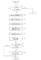
次に、図7は、本発明に係るアクセルペダル踏力制御の処理の流れを示すフローチャートであり、以下、これを説明する。 Next, FIG. 7 is a flowchart showing a flow of processing of accelerator pedal depression force control according to the present invention, which will be described below.
まずステップ1では、そのときのアクセルペダル2の位置つまりアクセル開度が所定のアクセル開度閾値よりも大きいか否かを判定する。所定のアクセル開度閾値よりも大きい場合のみステップ2へ進み、所定のアクセル開度閾値以下であれば、ルーチンを終了する。つまり、アクセル開度そのものが十分に小さい領域では、燃費を悪化させる無駄な加速が生じないため、本実施例では、アクセル開度変化速度によらずに踏力増加は行わない。 First, in step 1, it is determined whether or not the position of the accelerator pedal 2 at that time, that is, the accelerator opening is larger than a predetermined accelerator opening threshold. Only when it is larger than the predetermined accelerator opening threshold value, the routine proceeds to step 2, and when it is less than the predetermined accelerator opening threshold value, the routine is ended. That is, in the region where the accelerator opening itself is sufficiently small, useless acceleration that deteriorates the fuel consumption does not occur. Therefore, in this embodiment, the pedal effort is not increased regardless of the accelerator opening change speed.
ステップ2では、アクセルペダル2の開度が増加し始めたときの車速を検知し、前述したように、車速に応じた基本的な変化速度閾値を設定する。 In step 2, the vehicle speed when the opening of the accelerator pedal 2 starts to increase is detected, and the basic change speed threshold value corresponding to the vehicle speed is set as described above.
ステップ3では、そのときの運転モードに応じた変化速度閾値の補正を行う。具体的には、現在の運転モードが加速要求の高い運転モードであるほど変化速度閾値が大きくなるようにステップ2の基本的な変化速度閾値を補正する。 In step 3, the change speed threshold value is corrected according to the operation mode at that time. Specifically, the basic change speed threshold value in Step 2 is corrected so that the change speed threshold value increases as the current operation mode is an operation mode with a higher acceleration request.
ステップ4では、そのときの周囲の空気密度に応じた変化速度閾値の補正を行う。具体的には、空気密度が低いほど変化速度閾値が大きくなるように、変化速度閾値をさらに補正する。 In step 4, the change speed threshold value is corrected according to the ambient air density at that time. Specifically, the change speed threshold value is further corrected so that the change speed threshold value increases as the air density decreases.
ステップ5では、走行中の道路の勾配と車両の搭載重量とに関する補正を行う。具体的には、道路の勾配が大きいほど変化速度閾値が大きくなるように、また搭載重量が大きいほど変化速度閾値が大きくなるように、変化速度閾値をさらに補正する。
In
ステップ6では、前方車両との車間距離に基づく補正を行う。具体的には、前方車両との車間距離が大きいほど変化速度閾値が大きくなるように、変化速度閾値をさらに補正する。 In step 6, correction based on the inter-vehicle distance from the preceding vehicle is performed. Specifically, the change speed threshold value is further corrected so that the change speed threshold value increases as the inter-vehicle distance from the preceding vehicle increases.
ステップ7では、現在の車速と法定速度との差に基づく補正を行う。具体的には、現在の車速が走行中の道路の法定速度よりも低いことを条件として、法定速度までの速度差が大きいほど変化速度閾値が大きくなるように、変化速度閾値をさらに補正する。
In
なお、これらのステップ3〜ステップ7の補正は、補正係数の乗算や補正量の加算など適宜な方法で行うことが可能である。 Note that the corrections in Step 3 to Step 7 can be performed by an appropriate method such as multiplication of correction coefficients or addition of correction amounts.
ステップ8では、逐次算出されるアクセルペダル2の開度変化速度を、ステップ2〜7を経て最終的に決定された変化速度閾値と大小比較する。ここで、アクセルペダル2の開度変化速度が変化速度閾値よりも大きい場合には、ステップ9へ進み、アクセルペダル2の踏力をベース踏力よりも増加させる。
In
なお、上記実施例では、運転者によるアクセルペダル2の開度増加操作(全閉状態あるいは中間開度からの踏込)の初期における車速を基準として変化速度閾値を設定するようにしているが、アクセルペダル2の開度が増加している間の車速を逐次読み込んで逐次変化速度閾値を設定するようにしてもよい。 In the above embodiment, the change speed threshold is set based on the vehicle speed at the initial stage of the opening operation of the accelerator pedal 2 by the driver (depression from the fully closed state or the intermediate opening). The vehicle speed while the opening degree of the pedal 2 is increasing may be read sequentially to set the sequential change speed threshold.
またアクセルペダル2の開度は燃料消費率に相関し、アクセルペダル2の開度やその変化速度から瞬間的な燃料消費率を算出することができるので、この燃料消費率を運転席のインストルメントパネルまたはカーナビゲーション画面等に表示するようにすれば、運転者は、燃費が悪化するとアクセルペダル2の踏力が増加するということを視覚で把握しながら運転することができるので、燃費の低減を実現する上で有利となる。 Further, the opening degree of the accelerator pedal 2 correlates with the fuel consumption rate, and the instantaneous fuel consumption rate can be calculated from the opening degree of the accelerator pedal 2 and its change speed. By displaying on the panel or car navigation screen, the driver can drive while visually grasping that the pedaling force of the accelerator pedal 2 will increase if the fuel efficiency deteriorates, thus realizing a reduction in fuel consumption. This is advantageous.
なお、上記実施例では、燃料消費に関連するアクセル開度の変化速度に基づいて踏力増加を行っているが、燃料消費率そのものについて閾値を設定し、そのときの燃料消費率が閾値を超えたときに踏力増加を行う場合にも、本発明は同様に適用できる。 In the above embodiment, the pedal effort is increased based on the change rate of the accelerator opening degree related to fuel consumption. However, a threshold is set for the fuel consumption rate itself, and the fuel consumption rate at that time exceeds the threshold. The present invention can be applied to the case where the pedal effort is sometimes increased.
また上記実施例では、アクセルペダル2の位置(踏込量)そのものをアクセル開度として検出しており、従って、アクセルペダル2の位置の変化速度とアクセル開度変化速度とは実質的に同義であるが、アクセルペダル2に連動する例えばスロットルバルブの開度をアクセル開度として用い本発明の制御を行うことも可能である。 Further, in the above-described embodiment, the position (depression amount) of the accelerator pedal 2 itself is detected as the accelerator opening, and therefore, the change speed of the accelerator pedal 2 position and the accelerator opening change speed are substantially synonymous. However, it is also possible to perform the control of the present invention by using, for example, the opening of the throttle valve linked to the accelerator pedal 2 as the accelerator opening.
なお、本発明に係るアクセルペダル踏力制御装置は、内燃機関のみを駆動源とする車両にのみ適用されるものではなく、例えば電気自動車やハイブリッド自動車等にも適用可能である。 Note that the accelerator pedal depression force control apparatus according to the present invention is not only applied to a vehicle that uses only an internal combustion engine as a drive source, but is also applicable to, for example, an electric vehicle or a hybrid vehicle.
1…車体
2…アクセルペダル
3…回転軸
4…リターンスプリング
5…軸受
6…アクセルポジションセンサ
7…可変フリクションプレート
7a…摩擦部材
7b…摩擦部材
8…固定軸
9…アクチュエータ
10…コントロールユニット
DESCRIPTION OF SYMBOLS 1 ... Vehicle body 2 ... Accelerator pedal 3 ... Rotating shaft 4 ...
Claims (7)
上記変化速度閾値が車速に応じて設定され、車速が低い場合の変化速度閾値に対して車速が高い場合の変化速度閾値を相対的に大きく設定し、
さらに、周囲の空気密度を検知する手段を有し、空気密度が小さいほど変化速度閾値を大きくする、ことを特徴とするアクセルペダル踏力制御装置。 An accelerator opening change speed detecting means for detecting an accelerator opening change speed by a depression operation of an accelerator pedal provided in the vehicle, and a pedal force changing means for changing the pedal effort of the accelerator pedal, the accelerator opening changing speed In the accelerator pedal depression force control device that increases the depression force of the accelerator pedal more than the base depression force when is greater than a predetermined change speed threshold,
The change speed threshold is set according to the vehicle speed, and the change speed threshold when the vehicle speed is high is set to be relatively large with respect to the change speed threshold when the vehicle speed is low,
The accelerator pedal depression force control device further comprises means for detecting the ambient air density, and the change speed threshold value is increased as the air density decreases.
Priority Applications (8)
| Application Number | Priority Date | Filing Date | Title |
|---|---|---|---|
| JP2009123000A JP5326805B2 (en) | 2008-07-31 | 2009-05-21 | Accelerator pedal force control device |
| US13/055,006 US9533572B2 (en) | 2008-07-31 | 2009-07-31 | Accelerator reaction for control apparatus |
| CN2009801305697A CN102112336B (en) | 2008-07-31 | 2009-07-31 | Accelerator reaction for control apparatus |
| PCT/IB2009/006423 WO2010013133A1 (en) | 2008-07-31 | 2009-07-31 | Accelerator reaction for control apparatus |
| BRPI0916459A BRPI0916459A2 (en) | 2008-07-31 | 2009-07-31 | throttle reaction force control apparatus |
| KR1020117002236A KR101379104B1 (en) | 2008-07-31 | 2009-07-31 | Accelerator reaction for control apparatus |
| MX2011001136A MX2011001136A (en) | 2008-07-31 | 2009-07-31 | Accelerator reaction for control apparatus. |
| EP09802585.1A EP2318229B1 (en) | 2008-07-31 | 2009-07-31 | Accelerator reaction for control apparatus |
Applications Claiming Priority (5)
| Application Number | Priority Date | Filing Date | Title |
|---|---|---|---|
| JP2008197383 | 2008-07-31 | ||
| JP2008197384 | 2008-07-31 | ||
| JP2008197384 | 2008-07-31 | ||
| JP2008197383 | 2008-07-31 | ||
| JP2009123000A JP5326805B2 (en) | 2008-07-31 | 2009-05-21 | Accelerator pedal force control device |
Publications (2)
| Publication Number | Publication Date |
|---|---|
| JP2010052720A JP2010052720A (en) | 2010-03-11 |
| JP5326805B2 true JP5326805B2 (en) | 2013-10-30 |
Family
ID=42069075
Family Applications (2)
| Application Number | Title | Priority Date | Filing Date |
|---|---|---|---|
| JP2009122999A Active JP5381321B2 (en) | 2008-07-31 | 2009-05-21 | Accelerator pedal force control device |
| JP2009123000A Active JP5326805B2 (en) | 2008-07-31 | 2009-05-21 | Accelerator pedal force control device |
Family Applications Before (1)
| Application Number | Title | Priority Date | Filing Date |
|---|---|---|---|
| JP2009122999A Active JP5381321B2 (en) | 2008-07-31 | 2009-05-21 | Accelerator pedal force control device |
Country Status (9)
| Country | Link |
|---|---|
| US (1) | US9533572B2 (en) |
| EP (1) | EP2318229B1 (en) |
| JP (2) | JP5381321B2 (en) |
| KR (1) | KR101379104B1 (en) |
| CN (1) | CN102112336B (en) |
| BR (1) | BRPI0916459A2 (en) |
| MX (1) | MX2011001136A (en) |
| RU (1) | RU2466881C2 (en) |
| WO (1) | WO2010013133A1 (en) |
Families Citing this family (34)
| Publication number | Priority date | Publication date | Assignee | Title |
|---|---|---|---|---|
| JP5302095B2 (en) * | 2009-05-13 | 2013-10-02 | 本田技研工業株式会社 | Vehicle fuel consumption rate improvement support device |
| FR2956756B1 (en) * | 2010-02-23 | 2012-08-24 | Airbus Operations Sas | PERFECTED RESISTIVE TORQUE GENERATING DEVICE |
| JP5471829B2 (en) * | 2010-05-25 | 2014-04-16 | 日産自動車株式会社 | Accelerator pedal force control device for hybrid vehicle |
| JP5471856B2 (en) | 2010-06-07 | 2014-04-16 | 日産自動車株式会社 | Accelerator pedal force control device and accelerator pedal force control method |
| EP2583853B1 (en) * | 2010-06-15 | 2017-10-11 | Nissan Motor Co., Ltd | Accelerator pedal depression force setting method for accelerator pedal depression force control device |
| DE102010041537B4 (en) * | 2010-09-28 | 2021-04-15 | Bayerische Motoren Werke Aktiengesellschaft | Driver assistance system to support the driver in consumption-controlled driving |
| DE102010041544B4 (en) | 2010-09-28 | 2023-05-04 | Bayerische Motoren Werke Aktiengesellschaft | Driver assistance system to support the driver in consumption-controlled driving |
| JP5206802B2 (en) * | 2011-01-20 | 2013-06-12 | トヨタ自動車株式会社 | Vehicle travel control device |
| JP5740175B2 (en) * | 2011-02-21 | 2015-06-24 | 株式会社ミクニ | Accelerator pedal device |
| JP4881482B1 (en) * | 2011-06-02 | 2012-02-22 | 有限会社ジロウコレクション | Accelerator pedal pressure adjustment system for vehicles |
| US9176515B2 (en) * | 2011-07-05 | 2015-11-03 | Honda Motor Co., Ltd. | Accelerator pedal reaction force control device |
| DE102011088275A1 (en) * | 2011-12-12 | 2013-06-13 | Robert Bosch Gmbh | Pedal system for a vehicle |
| CN104755305B (en) | 2012-11-21 | 2017-06-13 | 本田技研工业株式会社 | Accelerator pedal reaction force control device and vehicle |
| KR101406489B1 (en) * | 2013-04-23 | 2014-06-12 | 기아자동차주식회사 | Active control method of accelerator pedal effort |
| RU2529923C1 (en) * | 2013-04-25 | 2014-10-10 | федеральное государственное бюджетное образовательное учреждение высшего профессионального образования "Южно-Российский государственный технический университет (Новочеркасский политехнический институт)" | Dc multi-motor electric drives control device |
| DE102013214371A1 (en) * | 2013-07-23 | 2015-01-29 | Robert Bosch Gmbh | Haptic motor vehicle accelerator pedal with elastically coupled actuator and method and control unit for regulating the same |
| GB201318706D0 (en) * | 2013-10-23 | 2013-12-04 | Jaguar Land Rover Ltd | Improvements in vehicle speed control |
| US10025341B2 (en) * | 2013-10-30 | 2018-07-17 | Honda Motor Co., Ltd. | Pedal reactive force controller |
| EP3751181B1 (en) | 2014-01-31 | 2022-01-12 | BRP-Rotax GmbH & Co. KG | A method of operating a vehicle |
| US9908409B2 (en) | 2014-08-29 | 2018-03-06 | Mazda Motor Corporation | Vehicle accelerator pedal reaction force control device |
| WO2016045687A1 (en) * | 2014-09-24 | 2016-03-31 | Volvo Truck Corporation | Method to control reaction force of an accelerator pedal system |
| JP6480762B2 (en) * | 2015-03-06 | 2019-03-13 | 株式会社Subaru | Control device for internal combustion engine |
| RU2676749C2 (en) * | 2016-08-26 | 2019-01-11 | Вячеслав Иванович Новоковский | Method for controlling internal combustion engine during its operation |
| JP6787040B2 (en) * | 2016-10-27 | 2020-11-18 | 株式会社アドヴィックス | Vehicle operation device |
| JP6702157B2 (en) * | 2016-11-25 | 2020-05-27 | トヨタ自動車株式会社 | Accelerator pedal reaction force application device |
| CN110062842B (en) * | 2016-12-07 | 2021-07-30 | 马自达汽车株式会社 | Vehicle control device |
| JP2018149933A (en) * | 2017-03-14 | 2018-09-27 | オムロン株式会社 | Control device, program, support device, and support method |
| EP3656596A4 (en) * | 2017-07-20 | 2021-03-24 | Mitsuba Corporation | Sudden start prevention device |
| KR20190049004A (en) * | 2017-11-01 | 2019-05-09 | 현대자동차주식회사 | Vehicle and method for controlling thereof |
| JP2019143539A (en) * | 2018-02-21 | 2019-08-29 | 本田技研工業株式会社 | vehicle |
| KR102637599B1 (en) * | 2018-10-08 | 2024-02-19 | 주식회사 에이치엘클레무브 | Apparatus and Method for Controlling Lane Changing using Vehicle-to-Vehicle Communication and Tendency Information Calculation Apparatus therefor |
| DE112019006781T5 (en) * | 2019-02-01 | 2021-10-21 | Mikuni Corporation | Accelerator pedal device |
| KR102163963B1 (en) * | 2019-04-23 | 2020-10-13 | 현대자동차주식회사 | System and method for controlling pedal effort of vehicle |
| JP2023031743A (en) * | 2021-08-25 | 2023-03-09 | 株式会社デンソー | accelerator pedal system |
Family Cites Families (40)
| Publication number | Priority date | Publication date | Assignee | Title |
|---|---|---|---|---|
| JPH01130832U (en) * | 1988-03-02 | 1989-09-06 | ||
| JP2658467B2 (en) * | 1990-01-22 | 1997-09-30 | 日産自動車株式会社 | Accelerator reaction force control device |
| JPH05231194A (en) * | 1992-02-26 | 1993-09-07 | Nippondenso Co Ltd | Stepping reaction force controller for accelerator pedal |
| RU2033931C1 (en) * | 1992-11-25 | 1995-04-30 | Иван Николаевич Алешков | Accelerator pedal |
| US5517410A (en) * | 1993-07-08 | 1996-05-14 | Toyota Jidosha Kabushiki Kaisha | Apparatus for controlling vehicle drive force depending upon vehicle load determined by engine load and vehicle speed |
| JP3669036B2 (en) * | 1996-03-18 | 2005-07-06 | 日産自動車株式会社 | Accelerator reaction force control device by climbing slope |
| JPH10166890A (en) * | 1996-12-04 | 1998-06-23 | Suzuki Motor Corp | Alarm device |
| JP3785959B2 (en) * | 2001-07-19 | 2006-06-14 | 日産自動車株式会社 | Vehicle travel control device |
| JP2003219230A (en) * | 2002-01-24 | 2003-07-31 | Sumitomo Electric Ind Ltd | Camera with irregular reflection prevention mechanism |
| JP3651793B2 (en) * | 2002-04-03 | 2005-05-25 | 本田技研工業株式会社 | Accelerator pedal device for vehicle |
| JP3838166B2 (en) * | 2002-06-20 | 2006-10-25 | 日産自動車株式会社 | Driving assistance device for vehicle |
| JP3941640B2 (en) * | 2002-09-18 | 2007-07-04 | 日産自動車株式会社 | VEHICLE DRIVE OPERATION ASSISTANCE DEVICE, VEHICLE DRIVE OPERATION ASSISTANCE METHOD, AND VEHICLE USING THE METHOD |
| JP2005090347A (en) * | 2003-09-17 | 2005-04-07 | Honda Motor Co Ltd | Accelerator pedal device for vehicle |
| JP4367089B2 (en) * | 2003-10-30 | 2009-11-18 | 日産自動車株式会社 | Accelerator pedal force control device |
| JP2005335648A (en) * | 2004-05-31 | 2005-12-08 | Nissan Motor Co Ltd | Information presentation device and method |
| JP4367254B2 (en) * | 2004-06-16 | 2009-11-18 | 日産自動車株式会社 | VEHICLE DRIVE OPERATION ASSISTANCE DEVICE AND VEHICLE HAVING VEHICLE DRIVE OPERATION ASSISTANCE DEVICE |
| JP2007076468A (en) * | 2005-09-13 | 2007-03-29 | Toyota Motor Corp | Control device of vehicle |
| JP5028789B2 (en) * | 2005-11-04 | 2012-09-19 | トヨタ自動車株式会社 | Driving assistance device for vehicle |
| JP4754969B2 (en) | 2006-01-10 | 2011-08-24 | 株式会社小松製作所 | Engine control device for work vehicle |
| JP5082243B2 (en) * | 2006-01-10 | 2012-11-28 | トヨタ自動車株式会社 | Vehicle driving assistance device |
| JP4765766B2 (en) * | 2006-05-23 | 2011-09-07 | 日産自動車株式会社 | VEHICLE DRIVE OPERATION ASSISTANCE DEVICE AND VEHICLE WITH VEHICLE DRIVE OPERATION ASSISTANCE DEVICE |
| KR100863429B1 (en) * | 2006-12-08 | 2008-10-16 | 현대자동차주식회사 | Accelerator pedal system |
| JP4835539B2 (en) * | 2007-08-10 | 2011-12-14 | トヨタ自動車株式会社 | Driving force control device |
| JP4785818B2 (en) * | 2007-11-02 | 2011-10-05 | 三菱電機株式会社 | Driving assistance device for vehicle |
| JP5278161B2 (en) * | 2008-07-29 | 2013-09-04 | 日産自動車株式会社 | Accelerator pedal reaction force control device |
| JP5256913B2 (en) * | 2008-07-31 | 2013-08-07 | 日産自動車株式会社 | Accelerator pedal force control device |
| JP5278162B2 (en) * | 2008-07-31 | 2013-09-04 | 日産自動車株式会社 | Accelerator pedal force control device |
| JP4553057B2 (en) * | 2008-07-31 | 2010-09-29 | 日産自動車株式会社 | Accelerator pedal depression force control device and method |
| JP4745418B2 (en) * | 2009-04-23 | 2011-08-10 | 本田技研工業株式会社 | Reaction force device |
| JP5481933B2 (en) * | 2009-05-25 | 2014-04-23 | 日産自動車株式会社 | Accelerator pedal force control device |
| JP5316339B2 (en) * | 2009-09-18 | 2013-10-16 | 日産自動車株式会社 | Accelerator pedal force control device |
| WO2011105125A1 (en) * | 2010-02-24 | 2011-09-01 | 日産自動車株式会社 | Accelerator pedal force control device |
| JP5471829B2 (en) * | 2010-05-25 | 2014-04-16 | 日産自動車株式会社 | Accelerator pedal force control device for hybrid vehicle |
| JP5471856B2 (en) * | 2010-06-07 | 2014-04-16 | 日産自動車株式会社 | Accelerator pedal force control device and accelerator pedal force control method |
| EP2583853B1 (en) * | 2010-06-15 | 2017-10-11 | Nissan Motor Co., Ltd | Accelerator pedal depression force setting method for accelerator pedal depression force control device |
| JP5367155B2 (en) * | 2010-09-21 | 2013-12-11 | 本田技研工業株式会社 | Accelerator pedal device for vehicle and pedal reaction force control method |
| JP5206802B2 (en) * | 2011-01-20 | 2013-06-12 | トヨタ自動車株式会社 | Vehicle travel control device |
| US9176515B2 (en) * | 2011-07-05 | 2015-11-03 | Honda Motor Co., Ltd. | Accelerator pedal reaction force control device |
| CN104755305B (en) * | 2012-11-21 | 2017-06-13 | 本田技研工业株式会社 | Accelerator pedal reaction force control device and vehicle |
| US9358885B2 (en) * | 2014-07-28 | 2016-06-07 | Honda Motor Co., Ltd. | Variable ratio throttle pedal |
-
2009
- 2009-05-21 JP JP2009122999A patent/JP5381321B2/en active Active
- 2009-05-21 JP JP2009123000A patent/JP5326805B2/en active Active
- 2009-07-31 US US13/055,006 patent/US9533572B2/en active Active
- 2009-07-31 KR KR1020117002236A patent/KR101379104B1/en not_active IP Right Cessation
- 2009-07-31 BR BRPI0916459A patent/BRPI0916459A2/en not_active IP Right Cessation
- 2009-07-31 CN CN2009801305697A patent/CN102112336B/en active Active
- 2009-07-31 MX MX2011001136A patent/MX2011001136A/en active IP Right Grant
- 2009-07-31 RU RU2011107196/11A patent/RU2466881C2/en not_active IP Right Cessation
- 2009-07-31 EP EP09802585.1A patent/EP2318229B1/en active Active
- 2009-07-31 WO PCT/IB2009/006423 patent/WO2010013133A1/en active Application Filing
Also Published As
| Publication number | Publication date |
|---|---|
| RU2466881C2 (en) | 2012-11-20 |
| KR20110036744A (en) | 2011-04-08 |
| RU2011107196A (en) | 2012-09-10 |
| EP2318229A1 (en) | 2011-05-11 |
| JP5381321B2 (en) | 2014-01-08 |
| KR101379104B1 (en) | 2014-04-04 |
| JP2010052720A (en) | 2010-03-11 |
| EP2318229A4 (en) | 2014-03-19 |
| CN102112336B (en) | 2013-12-25 |
| US20110125367A1 (en) | 2011-05-26 |
| US9533572B2 (en) | 2017-01-03 |
| MX2011001136A (en) | 2011-03-29 |
| CN102112336A (en) | 2011-06-29 |
| BRPI0916459A2 (en) | 2016-02-16 |
| WO2010013133A1 (en) | 2010-02-04 |
| EP2318229B1 (en) | 2014-10-22 |
| JP2010052719A (en) | 2010-03-11 |
Similar Documents
| Publication | Publication Date | Title |
|---|---|---|
| JP5326805B2 (en) | Accelerator pedal force control device | |
| JP5637263B2 (en) | Accelerator pedal force control device | |
| JP5481933B2 (en) | Accelerator pedal force control device | |
| JP2007076468A (en) | Control device of vehicle | |
| JP5229424B2 (en) | Accelerator pedal force control device | |
| US9261042B2 (en) | Vehicle start control device | |
| JPWO2011092886A1 (en) | Accelerator pedal force control device | |
| JP5293892B2 (en) | Setting method of accelerator pedal depression force of accelerator pedal depression force control device | |
| JP7070325B2 (en) | Vehicle control device | |
| JP2011063149A (en) | Accelerator pedalling force control device | |
| JP4520845B2 (en) | Automatic transmission |
Legal Events
| Date | Code | Title | Description |
|---|---|---|---|
| A621 | Written request for application examination |
Free format text: JAPANESE INTERMEDIATE CODE: A621 Effective date: 20120424 |
|
| A131 | Notification of reasons for refusal |
Free format text: JAPANESE INTERMEDIATE CODE: A131 Effective date: 20130514 |
|
| A521 | Written amendment |
Free format text: JAPANESE INTERMEDIATE CODE: A523 Effective date: 20130606 |
|
| TRDD | Decision of grant or rejection written | ||
| A01 | Written decision to grant a patent or to grant a registration (utility model) |
Free format text: JAPANESE INTERMEDIATE CODE: A01 Effective date: 20130625 |
|
| A61 | First payment of annual fees (during grant procedure) |
Free format text: JAPANESE INTERMEDIATE CODE: A61 Effective date: 20130708 |
|
| R150 | Certificate of patent or registration of utility model |
Ref document number: 5326805 Country of ref document: JP Free format text: JAPANESE INTERMEDIATE CODE: R150 Free format text: JAPANESE INTERMEDIATE CODE: R150 |