JP5323712B2 - Inter-cell power control for interference management - Google Patents
Inter-cell power control for interference management Download PDFInfo
- Publication number
- JP5323712B2 JP5323712B2 JP2009535456A JP2009535456A JP5323712B2 JP 5323712 B2 JP5323712 B2 JP 5323712B2 JP 2009535456 A JP2009535456 A JP 2009535456A JP 2009535456 A JP2009535456 A JP 2009535456A JP 5323712 B2 JP5323712 B2 JP 5323712B2
- Authority
- JP
- Japan
- Prior art keywords
- psd
- node
- cell
- terminal node
- control
- Prior art date
- Legal status (The legal status is an assumption and is not a legal conclusion. Google has not performed a legal analysis and makes no representation as to the accuracy of the status listed.)
- Expired - Fee Related
Links
- 238000000034 method Methods 0.000 claims abstract description 34
- 230000005540 biological transmission Effects 0.000 claims description 34
- 230000003595 spectral effect Effects 0.000 claims description 10
- 238000005259 measurement Methods 0.000 claims description 6
- 230000002452 interceptive effect Effects 0.000 claims description 4
- 238000004891 communication Methods 0.000 description 47
- 230000006870 function Effects 0.000 description 27
- 238000012360 testing method Methods 0.000 description 17
- 230000011664 signaling Effects 0.000 description 15
- 238000012545 processing Methods 0.000 description 8
- 230000008901 benefit Effects 0.000 description 6
- 238000010586 diagram Methods 0.000 description 6
- 238000012795 verification Methods 0.000 description 6
- 239000000523 sample Substances 0.000 description 5
- 230000008859 change Effects 0.000 description 4
- 238000013507 mapping Methods 0.000 description 4
- 230000007246 mechanism Effects 0.000 description 4
- 230000006978 adaptation Effects 0.000 description 3
- 239000003795 chemical substances by application Substances 0.000 description 3
- 230000008569 process Effects 0.000 description 3
- 238000012546 transfer Methods 0.000 description 3
- 230000010267 cellular communication Effects 0.000 description 2
- 230000001413 cellular effect Effects 0.000 description 2
- 230000007423 decrease Effects 0.000 description 2
- 238000005516 engineering process Methods 0.000 description 2
- 239000000835 fiber Substances 0.000 description 2
- 230000007774 longterm Effects 0.000 description 2
- 230000000116 mitigating effect Effects 0.000 description 2
- 230000000737 periodic effect Effects 0.000 description 2
- 230000007704 transition Effects 0.000 description 2
- RYGMFSIKBFXOCR-UHFFFAOYSA-N Copper Chemical compound [Cu] RYGMFSIKBFXOCR-UHFFFAOYSA-N 0.000 description 1
- 230000004075 alteration Effects 0.000 description 1
- 238000013459 approach Methods 0.000 description 1
- 238000013475 authorization Methods 0.000 description 1
- 238000005452 bending Methods 0.000 description 1
- 238000004590 computer program Methods 0.000 description 1
- 239000012141 concentrate Substances 0.000 description 1
- 239000010949 copper Substances 0.000 description 1
- 229910052802 copper Inorganic materials 0.000 description 1
- 238000012937 correction Methods 0.000 description 1
- 230000001186 cumulative effect Effects 0.000 description 1
- 230000003247 decreasing effect Effects 0.000 description 1
- 230000000694 effects Effects 0.000 description 1
- 238000011156 evaluation Methods 0.000 description 1
- 230000000977 initiatory effect Effects 0.000 description 1
- 238000012986 modification Methods 0.000 description 1
- 230000004048 modification Effects 0.000 description 1
- 230000003287 optical effect Effects 0.000 description 1
- 230000035515 penetration Effects 0.000 description 1
- 230000009467 reduction Effects 0.000 description 1
- 230000004044 response Effects 0.000 description 1
- 230000002441 reversible effect Effects 0.000 description 1
- 230000008054 signal transmission Effects 0.000 description 1
- 238000004088 simulation Methods 0.000 description 1
- 238000001228 spectrum Methods 0.000 description 1
Images


Classifications
-
- H—ELECTRICITY
- H04—ELECTRIC COMMUNICATION TECHNIQUE
- H04W—WIRELESS COMMUNICATION NETWORKS
- H04W52/00—Power management, e.g. Transmission Power Control [TPC] or power classes
- H04W52/04—Transmission power control [TPC]
- H04W52/06—TPC algorithms
- H04W52/10—Open loop power control
-
- H—ELECTRICITY
- H04—ELECTRIC COMMUNICATION TECHNIQUE
- H04L—TRANSMISSION OF DIGITAL INFORMATION, e.g. TELEGRAPHIC COMMUNICATION
- H04L27/00—Modulated-carrier systems
- H04L27/26—Systems using multi-frequency codes
-
- H—ELECTRICITY
- H04—ELECTRIC COMMUNICATION TECHNIQUE
- H04W—WIRELESS COMMUNICATION NETWORKS
- H04W52/00—Power management, e.g. Transmission Power Control [TPC] or power classes
- H04W52/04—Transmission power control [TPC]
- H04W52/06—TPC algorithms
- H04W52/08—Closed loop power control
-
- H—ELECTRICITY
- H04—ELECTRIC COMMUNICATION TECHNIQUE
- H04W—WIRELESS COMMUNICATION NETWORKS
- H04W52/00—Power management, e.g. Transmission Power Control [TPC] or power classes
- H04W52/04—Transmission power control [TPC]
- H04W52/18—TPC being performed according to specific parameters
- H04W52/24—TPC being performed according to specific parameters using SIR [Signal to Interference Ratio] or other wireless path parameters
- H04W52/242—TPC being performed according to specific parameters using SIR [Signal to Interference Ratio] or other wireless path parameters taking into account path loss
Landscapes
- Engineering & Computer Science (AREA)
- Computer Networks & Wireless Communication (AREA)
- Signal Processing (AREA)
- Mobile Radio Communication Systems (AREA)
Abstract
Description
本特許出願は、2006年11月1日に提出された、“干渉管理のためのセル間電力制御のための方法および装置”と題する米国仮特許出願番号第60/863,928号の優先権を主張する。前述の仮出願の全体は参照としてここに組み込まれる。 This patent application is the priority of US Provisional Patent Application No. 60 / 863,928, filed Nov. 1, 2006, entitled “Method and Apparatus for Inter-cell Power Control for Interference Management”. Insist. The entirety of the aforementioned provisional application is incorporated herein by reference.
下記の記載は一般に無線通信に係わり、特に、OFDMシステムにおける干渉管理のためのセル間電力制御に関する。 The following description relates generally to wireless communications, and more particularly to inter-cell power control for interference management in OFDM systems.
一般的な負荷制御のシナリオは閉ループ制御または開ループ制御の何れかに集中している。ループ制御の両方の型を統合することに関しては限定的な見解しかない。非直交システムにおいては、両方の型のループ制御を含む方法がスペクトル拡散時分割システムに向けられ、また単一セルへの適用に向けられている。直交システムにおいては、上りリンクの干渉制御に関して2つの大きな流派がある。1つの陣営は閉ループPSD制御を好み、他方、他の陣営は開ループPSD制御を好む。どちらの方法も長所と短所を有する。 Common load control scenarios concentrate on either closed-loop control or open-loop control. There is only a limited view on integrating both types of loop control. In non-orthogonal systems, methods involving both types of loop control are directed to spread spectrum time division systems and are intended for single cell applications. In orthogonal systems, there are two major schools of uplink interference control. One faction prefers closed loop PSD control while the other faction prefers open loop PSD control. Both methods have advantages and disadvantages.
一般的には閉ループ電力制御方式は非常に高速で、開ループ制御方式に対する必要性はほとんどないという認識がある。しかしながら、閉ループ制御の精度に関して心配があり、また適切な開始点がないと閉ループの手法は十分に高速であるとは云えないという心配がある。 It is generally recognized that closed loop power control schemes are very fast and there is little need for open loop control schemes. However, there are concerns about the accuracy of the closed loop control and there is a concern that the closed loop approach cannot be fast enough without an appropriate starting point.
代表的な開ループ電力制御方式では、端末ノードは、ある決まった基地局のパラメータの典型的な値と共に、測定された全受信電力を使用して、端末ノードと基地局間の伝送損失の粗い評価値を得る。これ等の測定に基づいて、順方向リンク伝送損失が見積もられて、端末ノードの送信機に対する適切な開ループ電力制御設定を決定するために使用される。端末ノードの送信電力は見積もられた伝搬路損失に見合うように調整され、所定のレベルで基地局に到達する。セル内の全ての端末ノードは同一プロセスを使用し、理想的にはそれ等の信号は等しい電力で基地局に到達する。 In a typical open-loop power control scheme, a terminal node uses a measured total received power along with a typical value of a certain base station parameter to coarsely transmit loss between the terminal node and the base station. Get an evaluation value. Based on these measurements, the forward link transmission loss is estimated and used to determine the appropriate open loop power control settings for the terminal node transmitter. The transmission power of the terminal node is adjusted to match the estimated propagation path loss, and reaches the base station at a predetermined level. All terminal nodes in the cell use the same process and ideally their signals reach the base station with equal power.
基地局のパラメータは典型的には、アクセスチャネル上の初期伝送に対する開ループ電力見積りと同様、現在進行中の開ループ電力見積りにおいて、諸端末ノードにより使用されるべき(諸)補正因子(correction factor(s))を含む。従来のアルゴリズムは、端末ノードが所望する、アクセスチャネル上の最初のアクセスプローブ(access probe)のための、送信電力を見積もるために存在する。開ループ電力制御の定数の値は多数の動的に変動するパラメータ(例えば、セルの配置、ネットワークの負荷、セル内における端末ノードの所在地を含む)に依存するということは注意されるべきである。これ等の動的に変化する変数の何れもが先験的には(a priori)分らない。従って、最初のプローブ電力レベルは恐らく誤るであろう。その誤りは、移動局が基地局に近い場合、通信を確立するために必要とされるよりもかなり高すぎる電力レベルをもたらすことがあり得る。送信電力レベルが高すぎる場合、残りの移動局への不要な干渉が引き起こされて、システムの能力を低下させる。他方、もし該移動局が遠隔にあると、それは最初のアクセスプローブを低すぎる電力レベルで送信する可能性があり、追加のプローブが送られるという結果になる。通話のセットアップ時間を増大させることに加えて、追加のプローブはより多くの逆方向リンク干渉をもたらす。 The base station parameters are typically the correction factors to be used by the terminal nodes in the open loop power estimate currently in progress, as well as the open loop power estimate for the initial transmission on the access channel. (s)). Conventional algorithms exist to estimate the transmit power for the first access probe on the access channel desired by the terminal node. It should be noted that the value of the open loop power control constant depends on a number of dynamically varying parameters (eg, including cell placement, network load, and location of terminal nodes within the cell). . None of these dynamically changing variables are known a priori. Therefore, the initial probe power level is probably wrong. The error can result in a power level that is significantly higher than needed to establish communication when the mobile station is close to the base station. If the transmission power level is too high, unnecessary interference to the remaining mobile stations is caused, reducing the system's capacity. On the other hand, if the mobile station is remote, it may transmit the first access probe at a power level that is too low, resulting in additional probes being sent. In addition to increasing call setup time, the additional probes result in more reverse link interference.
都市キャニオン(Urban Canyon)地域も又改良された制御の必要があり、この場合、セルの通信範囲の形状が、該地域内における端末ノードの移動に対し、動的で且つ信頼性の欠如した負荷指示を課す可能性がある。角を曲がりそして強化されたセル電話送信電力を隣接セル中に噴射することは、単一のサービング・セル(serving cell)による制御が適当でないため、より良い制御方式を必要とする。 The Urban Canyon area also needs improved control, where the shape of the cell coverage is a dynamic and unreliable load for the movement of terminal nodes within the area. May impose instructions. Bending corners and injecting enhanced cell phone transmit power into adjacent cells requires a better control scheme, as control by a single serving cell is not appropriate.
それ故、ユーザ経験の有効性を最大にするために、他のセルからの干渉とセル境界におけるサービング・セルからの弱い信号に関する諸問題は、好ましい制御方法のために現状の技術水準が提供するよりも更に詳細に考察されるべきであるということが、先述の議論から理解されるであろう。 Therefore, in order to maximize the effectiveness of the user experience, problems with interference from other cells and weak signals from the serving cell at the cell boundary are provided by the state of the art for the preferred control method. It will be understood from the foregoing discussion that it should be considered in greater detail than.
下記は、開示された実施形態のいくつかの態様の基礎的理解を提供するために、簡素化された概要を提示する。本概要は広範な全体像ではなく、このような諸実施形態の中心的または決定的な要素を特定するようには意図されておらず、又、その範囲の輪郭を描こうとするものでもない。本概要の目的は、後に提示される更に詳細な説明の前段として、該記載された実施形態のいくつかの概念を簡単な形で提示することである。 The following presents a simplified summary in order to provide a basic understanding of some aspects of the disclosed embodiments. This summary is not an extensive overview and is not intended to identify key or critical elements of such embodiments, nor is it intended to outline the scope thereof. The purpose of this summary is to present some concepts of the described embodiments in a simplified form as a prelude to the more detailed description that is presented later.
直交システムでは、セル間干渉は複数セル・システムの非効率性をしばしば助長する。クレームに記載された主題の一態様は、2つ以上のセルの負荷命令を受聴する制御方式を提供する。これは、サービング・セルがその諸端末の送信によって他のセルに対して引き起こされる干渉に気付かないという一般的な限界を、端末ノードが克服することを可能にする。 In orthogonal systems, inter-cell interference often contributes to the inefficiency of multiple cell systems. One aspect of the claimed subject matter provides a control scheme that listens for load instructions for two or more cells. This allows the terminal node to overcome the general limitation that the serving cell is unaware of the interference caused to other cells by the terminal's transmissions.
ある態様では、直交上りリンクに関して、セル間干渉はセル内の通信範囲を指定する。該通信範囲は、HARQからもリンク・アダプテーションからも利益を受けることのない上りリンク制御回線(uplink Control)、及び、HARQから利益を受けそしてユーザ装置(UE)の速度次第でリンク・アダプテーションから利益を受けることも受けないこともあり得る上りリンク・データ回線(uplink Data)の双方に対して評価される必要がある。SI段階の間に行われる殆どのシステム・レベル解析では、シミュレーションは制御チャネルの通信範囲を考慮しない。5%ユーザデータのスループットは、上りリンク共有データ・チャネルにおいてHARQ及びリンク・アダプテーションから得られる利益の故に、システムの真の通信範囲を指示するための適切な基準ではない。上りリンクの効率的な機能化のためには、セル間干渉が上りリンクの負荷とは無関係にネットワークによって厳格に制御される必要がある。 In an aspect, for orthogonal uplink, inter-cell interference specifies a communication range within the cell. The range includes uplink control lines that do not benefit from either HARQ or link adaptation, and benefits from HARQ and link adaptation depending on the speed of the user equipment (UE). It needs to be evaluated for both uplink data links that may or may not receive. In most system level analysis performed during the SI phase, the simulation does not consider the communication range of the control channel. The throughput of 5% user data is not an appropriate criterion for indicating the true coverage of the system because of the benefits derived from HARQ and link adaptation in the uplink shared data channel. For efficient uplink functionality, inter-cell interference needs to be strictly controlled by the network regardless of the uplink load.
直交上りリンクを用いると、単一セルのシナリオではユーザ装置は他のユーザのリンク性能に影響を与えることなく最大の送信電力で送信することができる。複数セルのシナリオでは、そのような方策を用いるとセル境界にいるユーザ装置は他のセルに重大な干渉を注入してシステムの通信範囲を縮小する。しかしながら、セル内部のユーザ装置は一般的には他のセルにおける干渉を引き起こさない。安定で且つ最適なシステム動作のために、我々は、セル内部のユーザ装置はセル境界にいるユーザ装置よりも高い送信電力或いは高い電力スペクトル密度で送信することができることを観察する。従って、我々は上りリンクの干渉管理アルゴリズムに対して2つの目標を念頭に置く。即ち、1)セル間干渉を緩和する手段、及び、2)異なる複数のユーザに帯域を割り当てるためのスケジューラ(scheduler)の柔軟性である。更に、従来の前提は、それぞれのユーザ装置は上りリンクにおいて単一のサービング・セルを有するということ、及び、該サービング・セルはその端末からの送信によって他のセルに対して引き起こされる干渉について一般的には気付かないということを包含している。 When orthogonal uplink is used, in a single cell scenario, a user apparatus can transmit with maximum transmission power without affecting the link performance of other users. In a multi-cell scenario, using such a strategy, user equipment at the cell boundary injects significant interference into other cells and reduces the system coverage. However, user equipment inside a cell generally does not cause interference in other cells. For stable and optimal system operation, we observe that user equipment inside the cell can transmit at higher transmit power or higher power spectral density than user equipment at the cell boundary. Therefore, we have two goals in mind for the uplink interference management algorithm. That is, 1) means for mitigating inter-cell interference, and 2) flexibility of a scheduler for allocating bandwidth to different users. Furthermore, the conventional premise is that each user equipment has a single serving cell in the uplink, and the serving cell is generally free of interference caused to other cells by transmissions from that terminal. It includes the fact that it is not noticed.
高いレベルの視点から、提案される閉ループPSD制御は、それぞれのセルが上りリンクの負荷インジケータ(indicator)(ビジー(busy)であるか否か)を下りリンクにおいて周期的に一斉送信することを伴う。また、それぞれのユーザ装置は少なくとも1つの主要な干渉するセルからの(伝搬路損失測定に基づく)該負荷インジケータ・ビットを復号すること、及び、該ユーザ装置はその許容された送信電力スペクトル密度を適切に低減することを伴う。更に詳しくは、参照PSD(例えば、CQIのような周期的な既知信号に基づくPSD)がノードBにおいて保持されてセル内電力制御のために使用される。ユーザ装置はPSDデルタと対応可能な帯域幅を周期的に通報する。参照PSDデルタは非サービング・セルからの負荷指示命令の関数であって、データ伝送に対して割り当てられた(許された)帯域幅はCQI帯域幅に等しいと仮定し、ユーザ装置において利用可能な電力ヘッドルーム(headroom)を指示する。ユーザ装置がデータを送信する最大送信電力制約とPSDが与えられれば、対応可能な帯域幅は最大送信電力と送信PSDから計算されてユーザ装置によってサポートされることができる最大帯域幅を指示する。ノードBは帯域幅(例えば、サブキャリア数)とパケット・フォーマット(例えば、パケット・サイズと変調方式)から構成される上りリンク割り当てを与える。割り当て帯域幅は対応可能な帯域幅よりも当然低いことが認識されるべきである。ユーザ装置は該PSDデルタを用い該割り当てに従ってパケットを送信する。 From a high level perspective, the proposed closed-loop PSD control involves periodically broadcasting uplink load indicators (whether busy or not) in the downlink. . Each user equipment also decodes the load indicator bits (based on channel loss measurements) from at least one primary interfering cell, and the user equipment determines its allowed transmit power spectral density. With proper reduction. More specifically, a reference PSD (eg, a PSD based on a periodic known signal such as CQI) is maintained at Node B and used for intra-cell power control. The user equipment periodically reports the available bandwidth for the PSD delta. The reference PSD delta is a function of the load indication command from the non-serving cell and is available at the user equipment, assuming that the allocated (allowed) bandwidth for data transmission is equal to the CQI bandwidth Directs the power headroom. Given the maximum transmit power constraint and PSD for the user equipment to transmit data, the available bandwidth is calculated from the maximum transmit power and the transmit PSD to indicate the maximum bandwidth that can be supported by the user equipment. Node B provides an uplink allocation consisting of bandwidth (eg, number of subcarriers) and packet format (eg, packet size and modulation scheme). It should be recognized that the allocated bandwidth is naturally lower than the available bandwidth. The user equipment transmits the packet according to the assignment using the PSD delta.
別の態様はスケジューラにセル間干渉を緩和する柔軟性を与えることを規定する。それぞれのセルに対するスケジューラは該セル領域内の端末ノードに可変な帯域幅と電力スペクトル密度(power spectral density)(PSD)を割り当てる柔軟性を有する。該スケジューラはセル中央にいる端末ノードに対してより高い送信電力の利用を許可する。セル中央では該より高い送信電力の利用は他のセルとの干渉を引き起こさない。 Another aspect provides that the scheduler is given the flexibility to mitigate inter-cell interference. The scheduler for each cell has the flexibility to allocate variable bandwidth and power spectral density (PSD) to terminal nodes in the cell region. The scheduler permits the use of higher transmission power to the terminal node in the center of the cell. In the center of the cell, utilization of the higher transmission power does not cause interference with other cells.
別の態様は開ループ制御と閉ループ制御双方を使用する方法を提供する。端末ノードの利用開始時に最初開ループPSD制御を用いることによって、閉ループプロセスにおける精度的な心配が緩和される。一旦初期目標値が設定されると、制御は閉ループ方式に切り替えられ、開ループプロセスに関連付けられる誤差と不確定性が軽減される。 Another aspect provides a method of using both open loop control and closed loop control. By using the first open-loop PSD control at the beginning of terminal node usage, the accuracy concerns in the closed-loop process are alleviated. Once the initial target value is set, control is switched to a closed loop scheme, reducing errors and uncertainties associated with the open loop process.
別の態様では、端末ノードが伝搬路損失値の鋭い変動を受ける場合、閉ループ制御のための目標値の再設定は利用開始時の状態に類似することになって、本方法は開ループシステムと閉ループシステム双方の利点を獲得する。 In another aspect, if the terminal node undergoes sharp fluctuations in the channel loss value, resetting the target value for closed loop control will be similar to the state at the beginning of use, and the method may be Gain the benefits of both closed-loop systems.
1つの態様はOFDMシステムにおけるセル間干渉制御を容易にする方法を提供する。その方法は、端末ノードからサービング・ノードへの及び端末ノードから隣接する非サービング・ノードへの双方に対する伝搬路損失の読み値を利用する受信された目標値を使用すること、端末ノードの使用開始時に或いは端末ノードの伝搬路損失関数の大きな変動時に開ループPSD制御を使用すること、及び、適切な時間に閉ループPSD制御に切り替えることを備える。 One aspect provides a method that facilitates inter-cell interference control in an OFDM system. The method uses a received target value that utilizes channel loss readings both from the terminal node to the serving node and from the terminal node to the adjacent non-serving node; Using open loop PSD control at times or during large fluctuations in the terminal node's propagation loss function, and switching to closed loop PSD control at the appropriate time.
別の態様は下記の動作を実行するためのコンピュータ実行可能な命令を記憶したコンピュータ可読媒体を提供する。該動作は即ち、端末ノードからサービング・ノードへの及び端末ノードから隣接する非サービング・ノードへの双方に対する伝搬路損失の読み値を利用する受信された目標値を使用すること、端末ノードの使用開始時に或いは端末ノードの伝搬路損失関数の大きな変動時に開ループPSD制御を使用すること、及び、適切な時間に閉ループPSD制御に切り替えることである。 Another aspect provides a computer-readable medium having stored thereon computer-executable instructions for performing the following operations. The operation is that of using a received target value that utilizes channel loss readings both from the terminal node to the serving node and from the terminal node to the adjacent non-serving node; Use open-loop PSD control at the start or during large fluctuations in the terminal node's propagation loss function, and switch to closed-loop PSD control at the appropriate time.
別の態様はOFDMシステムにおけるセル間干渉を制御するためのコードを実行するプロセッサで、端末ノードからサービング・ノードへの及び端末ノードから隣接する非サービング・ノードへの双方に対する伝搬路損失の読み値を利用する受信された目標値を使用するために、端末ノードの使用開始時に或いは端末ノードの伝搬路損失関数の大きな変動時に開ループPSD制御を使用するために、及び、適切な時間に閉ループPSD制御に切り替えるために、記憶媒体上に記憶されたコンピュータ実行可能なコードを実行するプロセッサである。 Another aspect is a processor that executes code for controlling inter-cell interference in an OFDM system, with channel loss readings both from the terminal node to the serving node and from the terminal node to adjacent non-serving nodes. In order to use the received target value utilizing the ノ ー ド, to use the open-loop PSD control at the start of use of the terminal node or when the terminal node's propagation loss function varies greatly, and at the appropriate time, the closed-loop PSD A processor that executes computer-executable code stored on a storage medium for switching to control.
更に別の態様はOFDMシステムにおけるセル間干渉制御を容易にするシステムを提示し、該システムは端末ノードからサービング・ノードへの及び端末ノードから隣接する非サービング・ノードへの双方に対する伝搬路損失の読み値を利用する受信された目標値を使用するための手段と、端末ノードの使用開始時に或いは端末ノードの伝搬路損失関数の大きな変動時に開ループPSD制御を使用するための手段と、及び、適切な時間に閉ループPSD制御に切り替えるための手段とを備える。 Yet another aspect presents a system that facilitates inter-cell interference control in an OFDM system, wherein the system reduces propagation path loss both from a terminal node to a serving node and from a terminal node to an adjacent non-serving node. Means for using the received target value utilizing the reading, means for using open-loop PSD control at the start of use of the terminal node or when there is a large variation in the terminal node's propagation loss function, and Means for switching to closed loop PSD control at an appropriate time.
上述の、及び関連する目的の達成のために、1又は複数の実施形態は以下に十分に説明されそして特に請求項の範囲において指摘される諸特徴を具備する。下記の説明と添付された図面は幾つかのある例示的な態様を詳細に記載し、そして、該実施形態の諸原理が利用されることができる種々の方法を数例示す。その他の諸利点と新規な諸特徴は下記の詳細な説明から、図面と合わせて考慮されると明白になるであろう、そして、開示される諸実施形態は全てのその様な態様及びそれ等の同等物を含むように意図される。 To the accomplishment of the foregoing and related ends, the one or more embodiments comprise the features fully described below and particularly pointed out in the claims. The following description and the annexed drawings set forth in detail certain illustrative aspects and illustrate several examples of the various ways in which the principles of the embodiments may be utilized. Other advantages and novel features will become apparent from the following detailed description when considered in conjunction with the drawings, and the disclosed embodiments cover all such aspects and the like. Is intended to include the equivalent of
種々の実施形態が図面を参照してここに説明される。図面では同じ参照番号は全体を通して同じ要素を指すために使用される。下記の説明では、説明目的のために、多くの具体的な詳細が1又は複数の実施形態の完全な理解を提供するために記載される。しかしながら、このような(諸)実施形態はこれ等の具体的な詳細がなくても実行されうることは明らかである。他の例では、既知の構成と装置が1又は複数の実施形態を説明することを容易にするためにブロック図の形式で示される。 Various embodiments are now described with reference to the drawings. In the drawings, like reference numerals are used to refer to like elements throughout. In the following description, for purposes of explanation, numerous specific details are set forth in order to provide a thorough understanding of one or more embodiments. It will be apparent, however, that such embodiment (s) may be practiced without these specific details. In other instances, well-known structures and devices are shown in block diagram form in order to facilitate describing one or more embodiments.
更に、種々の実施形態は本明細書中で無線端末に関連して説明される。無線端末はユーザに音声接続及び/又はデータ接続を提供する装置を指す。無線端末は、ラップトップ(laptop)計算機やデスクトップ(desktop)計算機のような計算装置に接続され、又はそれは携帯情報端末(personal digital assistant)(PDA)のような自己収容型装置であり得る。無線端末は、システム、加入者ユニット、加入者局、移動局、モバイル、遠隔局、接続点、遠隔端末、接続端末、ユーザ端末、ユーザ・エージェント(user agent)、ユーザ装置、或いはユーザ設備とも呼ばれる。無線端末は加入者局、無線装置、セルラ電話、PCS電話、無線電話、セッション・イニシエーション・プロトコル(Session Initiation Protocol)(SIP)電話、無線ローカル・ループ(wireless local loop)(WLL)局、携帯情報端末(PDA)、無線接続能力を備えたハンドヘルド(handheld)、或いは無線モデム(modem)に接続されるその他の処理装置であり得る。 Moreover, various embodiments are described herein in connection with a wireless terminal. A wireless terminal refers to a device that provides a voice connection and / or a data connection to a user. The wireless terminal is connected to a computing device such as a laptop computer or a desktop computer, or it can be a self-contained device such as a personal digital assistant (PDA). A wireless terminal is also called system, subscriber unit, subscriber station, mobile station, mobile, remote station, connection point, remote terminal, connection terminal, user terminal, user agent, user equipment, or user equipment . Wireless terminals include subscriber stations, wireless devices, cellular telephones, PCS telephones, wireless telephones, Session Initiation Protocol (SIP) telephones, wireless local loop (WLL) stations, mobile information It can be a terminal (PDA), a handheld with wireless connection capability, or other processing device connected to a wireless modem.
基地局(例えば、中継点)は、1又は複数のセクタを経由し、無線インターフェースを介して無線端末と通信するアクセス・ネットワークにおける装置を指す。基地局は、受信された無線インターフェース・フレームをIPパケットに変換することによって、IPネットワークを含み、該無線端末と残りのアクセス・ネットワークとの間のルータとして動作する。基地局は又無線インターフェースに対する属性管理を調整する。 A base station (eg, a relay point) refers to a device in an access network that communicates with a wireless terminal via a wireless interface via one or more sectors. The base station operates as a router between the wireless terminal and the rest of the access network, including the IP network, by converting received radio interface frames into IP packets. The base station also coordinates attribute management for the air interface.
更に、本明細書に記載される種々の態様又は特徴は、方法、装置、又は標準的なプログラム法及び/又はエンジニアリング技術を使用する生産品として実現される。本明細書で使用される用語“生産品”は、任意のコンピュータ可読装置、キャリア(carrier)、又は媒体から接続可能なコンピュータ・プログラムを網羅すると意図される。例えば、コンピュータ可読媒体は、磁気記憶装置(例えば、ハードディスク、フロッピー(登録商標)ディスク、磁気テープ、等々)、光学ディスク(例えば、コンパクトディスク(CD)、デジタル多用途ディスク(DVD)、等々)、スマート・カード(smart cards)、及びフラッシュメモリ(flash memory)装置(例えば、EPROM、カード、スティック(stick)、キードライブ(key drive)、等々)を含みうるが、これ等に限定されない。更に、本明細書に記載される種々の記憶メディアは、情報を記憶するための1又は複数の装置及び/又はその他の機械可読媒体を表すことができる。用語“機械可読媒体”は(複数の)命令及び/又はデータを記憶する、含有する、及び/又は搬送することができる無線チャネルとその他の種々の媒体を含みうるが、これ等に限定されない。 Moreover, various aspects or features described herein may be implemented as a method, apparatus, or product using standard programming methods and / or engineering techniques. The term “product” as used herein is intended to encompass a computer program connectable from any computer-readable device, carrier, or medium. For example, computer readable media include magnetic storage devices (eg, hard disks, floppy disks, magnetic tapes, etc.), optical disks (eg, compact disks (CD), digital versatile disks (DVD), etc.), Smart cards and flash memory devices (eg, EPROMs, cards, sticks, key drives, etc.) may be included, but are not limited to these. Additionally, various storage media described herein can represent one or more devices and / or other machine-readable media for storing information. The term “machine-readable medium” may include, but is not limited to, wireless channels and various other media that may store, contain, and / or carry instruction (s) and / or data.
図1を参照して、無線通信システム100が本明細書で提示される種々の実施形態に従って図示されている。該システム100はハイブリッド(hybrid)閉ループ及び開ループ制御を提供する。システム100は、基地局102(N個の基地局−Nは整数である)、無線端末(又はユーザ装置(UE))104(M個の無線端末−Mは整数である)、それぞれの電力制御器106、それぞれの無線端末検証器108、それぞれの検証比較器110、及びスケジューラ120を含む。直交システムでは、セル間干渉はしばしば複数セル・システムの非効率性を助長する。隣接セルに関連する伝搬路損失がセル間干渉を緩和することを容易にするために評価される。該システムは負荷インジケータを用いて開ループ制御と閉ループ制御を共に利用してセル間干渉を緩和する。そして、特に、無線端末104に対し2以上のセルの負荷命令を受聴する制御方式を提供する。隣接セルからの負荷命令は無線インターフェースを介して搬送され、或いは、該命令はバックホール(backhaul)を介してeNode−B間通信を経由しサービング・セルによって搬送される。これは、サービング・セルが諸端末の送信によって引き起こされる他のセルへの干渉について気付かないという一般的な限界を端末ノードが克服することを可能にする。
With reference to FIG. 1, a
最初、無線端末104が始動する場合、該端末は基地局102により開ループ制御関数を介して制御されて目標電力と目標受信機干渉レベルを設定する。更に、該UEがあるネットワークに入る場合、若しくは該UEが突然伝搬損失の急激な変化を受ける場合、該UEの送信PSDは、ダウンロード(download)(DL)伝搬路損失に基づいて高速更新のために割り当てるべき開ループ・アルゴリズムによって調整される。開ループ・アルゴリズムは、目標受信信号対雑音比(signal to noise ratio)(SNR)がサービング・セル及び隣接する非サービング・セルへの伝搬路損失の関数にされ得るという意味で、ある程度干渉レベルを制御する。開ループ・アルゴリズムは一般的には別のセルに注入される干渉に対して厳しい制御を有することはないので、UE104は後に、隣接する非サービング・セルからの負荷インジケータを受聴することによって自身の送信PSDを更新する。隣接セルからの負荷命令は無線インターフェースを介して搬送され、或いは、該命令はバックホールを介してeNode−B間通信を経由しサービング・セルによって搬送される。負荷命令が無線インターフェースを介して搬送される場合、隣接する非サービング・セルが目標と比較して高い干渉レベルを感ずると、負荷降下命令が該隣接セルからUEに送られる−その他の場合上昇命令送信される。UE104は、一旦降下命令を受信すると、自身の送信PSDを低下させる、その他の場合、それは自身の送信PSDを上昇させる。負荷命令がバックホールを介しeNode−B間通信を経由して搬送される場合、サービング・セルは隣接セルから受信された負荷命令に従って該UEの送信PSDを調整する。該調整はスケジューリング命令中に包含され、若しくは、該調整はサービング・セルが該UEに負荷命令を送ることによって行われる。負荷命令に対応する該PSD調整は開ループ制御に対応するそれよりは急激になり得ないことが認識されるべきである。負荷インジケータは他のセルによって見られる干渉レベルを示すので、厳しい干渉制御が達成されることができ、従って、高速で且つ厳しい干渉制御が獲得される。
Initially, when the
スケジューラ120はスケジューラにセル間干渉を緩和する柔軟性を許容する。−それぞれのセルに対するスケジューラ120はその領域内の端末ノードに可変帯域幅と電力スペクトル密度(PSD)を割り当てる柔軟性を有する。スケジューラ120はセル中央の端末ノードに対してより高い送信電力使用を許可する。セル中央では該より高い電力使用は他のセルとの干渉を引き起こさない。
The
システム100は無線端末104への無線通信信号を受信、送信、再送(等々)する基地局102を具備する。更に、システム100は、基地局102と同様の102n2及び102nNのような複数の基地局、及び/又は無線端末104と同様の104m2及び102mMのような複数の無線端末を含むことが予期される。議論は簡明を期して単一の局に絞られるが、諸態様は複数の基地局と複数の無線端末を含むことが認識されるべきである。基地局102は送信機チェーン(chain)と受信機チェーンを具備し、それ等のそれぞれは、当業者によって理解されるように、信号送信と受信に関連付けられる複数のコンポーネント(components)(例えば、プロセッサ、変調器、マルチプレクサ(multiplexers)、復調器、逆マルチプレクサ、アンテナ、等々)を具備する。基地局102は固定局及び/又は移動局である。無線端末104は、例えば、セルラ電話、スマート・フォン(smart phone)、ラップトップ、ハンドヘルド通信装置、ハンドヘルド計算装置、衛星ラジオ、全地球測位システム、PDA、及び/又は無線通信システム100を介するその他任意の通信のための装置である。又、無線端末104は固定式または移動式である。
The
無線端末104は任意の所与の瞬間に下りリンク及び/又は上りリンク・チャネル上で基地局102(及び/又は本質的に異なる(諸)基地局)と通信する。下りリンクは基地局102から無線端末104への通信リンクを指し、そして上りリンク・チャネルは無線端末104から基地局102への通信リンクを指す。基地局102は更に他の(諸)基地局、及び/又は、例えば無線端末104の認証および認可、アカウンティング(accounting)、ビリング(billing)等々のような機能を遂行する(図示されない)任意の本質的に異なる諸装置(例えば、サーバ)と通信する。
The
基地局102は電力制御器106と無線端末検証器108を更に含む。電力制御器106は無線端末104(及び/又は任意の本質的に異なる無線端末)に関連付けられる電力レベルを測定する。更に、電力制御器106は電力レベルを調整することを容易にするために電力命令を無線端末104に送信する。例えば、電力制御器106は送信ユニットの第1サブセット(subset)に関連付けられる1又は複数の送信ユニットにおいて電力命令を送信する。該電力命令は、例えば、電力レベルを上げること、電力レベルを下げること、電力レベルをそのままにすること、及び類似の動作を指示する。電力を上げる又は下げる電力命令を受信すると、無線端末104は関連する電力レベルを固定された(例えば、事前設定された)量及び/又は可変量、変更する。事前設定される量は一定の諸因子(例えば、周波数再利用因子、種々異なる移動局におけるチャネル状態)に基づいて変えられる量である。更に、無線端末検証器108は、送信ユニットの第2サブセットに関連付けられる1又は複数の送信ユニットにおいて、無線端末(例えば、無線端末104)に関する端末識別子の関数として情報を送信する。その上、1又は複数のオン(ON)識別子が、セッションがオン状態の場合、それぞれの無線端末に付与され、そして、該オン識別子は送信ユニットの第1サブセットと第2サブセットに関連付けられる。送信ユニットは種々のフォーマット(例えば、時間領域、周波数領域、時間周波数双方の領域のハイブリッド)である。
電力制御器106は下りリンク電力制御チャネル(downlink power control channel)(DLPCCH)を介して電力命令を送信する。一例に従えば、無線端末104がセッションオン状態にアクセスすると、基地局102によって無線端末104に資源が配分される。このような資源は特定のDLPCCHセグメント(segments)、1又は複数のオン識別子等々を含む。該DLPCCHは(例えば、電力制御器106を使用する)基地局セクタ・アタッチメント・ポイント(base station sector attachment point)によって利用され、無線端末104の送信電力を制御する。
The
無線端末検証器108は、電力制御器106によって転送される電力命令と並んで、電力命令が通信する相手の無線端末(例えば、無線端末104)に関連付けられる情報を送信する。例えば、無線端末検証器108は無線端末(例えば、無線端末104)に関連付けられる端末識別子(例えば、スクランブリング・マスク(scrambling mask))の関数として情報を送信する。無線端末検証器108はこのような情報をDLPCCHを介して送信する。1つの例示に従えば、無線端末104に関連付けられる情報は電力制御器106からの電力制御命令送信のサブセットと共にDLPCCHを介して送信される。
Along with the power command transferred by the
無線端末104は、無線端末104に関連付けられる、受信情報を評価する検証情報比較器110を更に含む。検証情報比較器110は、無線端末104が基地局102によって規定された通りに諸資源を利用しているかどうかを判定するために、受信情報を解析する。従って、検証情報比較器110はDLPCCHを介して送信されるシンボルのQコンポーネント中に含まれる情報を評価する。例えば、基地局102は無線端末104に(複数の)識別子(例えば、セッション・オンID)を割り当てたとすると、検証情報比較器110は無線端末104が該割り当てられた(複数の)識別子に関連付けられる適切な資源を使用するかどうかを解析する。他の複数の例によれば、検証情報比較器110は、無線端末104が基地局102によって割り当てられたDLPCCHの諸セグメントを利用しているかどうか、及び/又は、基地局102が無線端末104に過去に割り当てた資源(例えば、セッションオンID)を再生利用したかどうかを判定する。
The
図2を参照して、種々の態様に従って実施される例示的な通信システム200(例えば、セルラ通信ネットワーク)が図説される。該システムは、通信リンク205、207、208、211、230、231、232、233、234、235、236、237、238、及び239によって相互接続された複数のノードを備える。例示的な通信システム200における複数のノードは、信号(例えば、メッセージ)を使用し通信プロトコル(例えば、インターネット・プロトコル(Internet Protocol)(IP))に基づいて情報を交換する。システム200の通信リンクは、例えば、電線、光ファイバ・ケーブル、及び/又は無線通信技術を使用して実現される。例示的な通信システム200は複数の端末ノード260、270、261、271、262、272を含み、それ等は複数のアクセス・ノード220、221、及び222を介して通信システム200にアクセスする。端末ノード260、270、261、271、262、272は、例えば、無線通信装置または無線通信端末である。そして、アクセス・ノード220、221、222は、例えば、無線アクセス・ルータ(routers)又は基地局である。例示的な通信システム200は又、相互接続性を提供するために使用される又は特定のサービスまたは機能を提供するために使用される多数の他のノード204、206、209、210、及び212を含む。具体的には、例示的な通信システム200は、端末ノードに付随する状態の移転及び保管に対応するために使用されるサーバ204を含む。サーバ・ノード204はAAAサーバ、コンテキスト・トランスファ・サーバ(Context Transfer Server)、AAAサーバとコンテキスト・トランスファ・サーバの機能性双方を含むサーバであり得る。
With reference to FIG. 2, illustrated is an example communications system 200 (eg, a cellular communications network) implemented in accordance with various aspects. The system comprises a plurality of nodes interconnected by
例示的な通信システム200は、サーバ204、ノード206及びホーム・エージェント・ノード(home agent node)209を含むネットワーク202を図示し、該サーバ以下はそれぞれ対応するネットワーク・リンク205、207及び208によって中間ネットワーク・ノード210に接続される。ネットワーク202中の中間ネットワーク・ノード210は又ネットワーク202の視界の外にあるネットワーク・ノードへの相互接続をネットワーク・リンク211を介して提供する。ネットワーク・リンク211は別の中間ネットワーク・ノード212に接続され、後者は複数のアクセス・ノード240、241、242への更なる接続性をそれぞれネットワーク・リンク230、231、232を介して提供する。
The
それぞれのアクセス・ノード240、240′、240″が、複数組のM個の端末ノード(260,270)(261,271)(262,272)それぞれに、それぞれ対応するアクセス・リンク(233,234)(235,236)(237,238)を介して接続性を提供するとして図示される。例示的な通信システム200では、それぞれのアクセス・ノード240、241、242は無線技術(例えば、無線アクセス・リンク)を使用してアクセスを提供するとして図示される。それぞれのアクセス・ノード240、241、242の無線通信範囲(例えば、通信セル250、251、及び252)は、それぞれ、対応するアクセス・ノードを囲む円として例示される。1つの態様では、複数の端末ノードが非サービング隣接アクセス・ノードへのアクセス・リンク239を使用する。上りリンク・データと下りリンク・データが端末ノードと多数の隣接するアクセス・ノードとの間で転送される。
Each access node 240, 240 ′, 240 ″ corresponds to each of a plurality of sets of M terminal nodes (260, 270) (261, 271) (262, 272), respectively, corresponding access links (233, 234). ) (235, 236) (237, 238) is illustrated as providing connectivity.In the
例示的な通信システム200は本明細書記載の種々の態様の説明のための基礎として提示される。更に、様々な異種のネットワーク・トポロジー(network topologies)が請求された主題の範囲内にあると意図される。該請求された主題においては、ネットワーク・ノードの数と型、アクセス・ノードの数と型、端末ノードの数と型、サーバ及びその他のエージェントの数と型、リンクの数と型、及びノード間の相互接続性は、図2に示される例示的な通信システム200のそれとは異なっていても良い。更に、例示的な通信システム200で示される機能的構成要素は省かれても結合されても良い。又、ネットワークにおける該機能的構成要素の所在地または配置は変更されても良い。
図3は複数セル環境の一態様を図説する。セル350はその領域内に端末ノード360から端末ノード370までを有する。セル351はその領域内に端末ノード361から端末ノード371までを有する。セル350は隣接セル351、352及び354を有するとして描かれている。セル351は隣接セル350、352及び353を有するとして描かれている。セル353はセル350に隣接しない。
FIG. 3 illustrates one aspect of a multiple cell environment.
それぞれのセルは主にそのセル内の諸端末ノードを制御する基地局を有する。それぞれの局において、基地局のスケジューラ120は該セル領域内の諸端末ノードに可変な帯域幅とPSDを割り当てる柔軟性を有する。端末ノード360は端末ノード370よりも高いPSDで動作することを許可される。該可変性は、セル・スループットを増大させて、セルの中央に近い端末ノード(例えば、360)に対してより大きな帯域幅とより高いPSDを与えることを期待される。もし端末ノード370がより高いPSDで送信することになれば、セル351近傍に位置している端末ノード371に対して干渉を引き起こす危険がある。
Each cell mainly has a base station that controls various terminal nodes in the cell. In each station, the
図4はセル間干渉の一態様を図説する。端末ノード471は静止しておりサービス・セル451の境界付近にいる。同じくセル451内にいる端末ノード461は端末ノード471から独立した電力及び/又は帯域幅で動作する。隣接セル450内には2つの端末ノードがある。セル450では、端末ノード470が増大させたPSD(例えば、端末ノード460より高いPSD)を用いて都市キャニオン480を通って移動している。端末ノード470は通路490上で該キャニオンの外へ移動して端末ノード471の方向へ曲がる。都市キャニオン状態からの突然の出口と端末ノード471への接近は端末ノード470と471に対する干渉の鋭い立ち上がり、及び、結果として生ずる伝搬路損失関数の大きな変化を引き起こす。伝搬路損失関数はサービング・セルに専ら縛られているわけではなく、端末ノードから隣接のサービング・セルへの伝搬路損失の関数でもあるということが注意される。本例では、隣接セル452に関する伝搬路損失は影響がない。端末ノード471はそのPSDを変化させなかった、或いは、自身のサービング・セル451からの命令を受けなかったことにも注意する。従来は、基地局440は端末ノード471に引き起こされる干渉に気付かない。一態様は開ループ制御がセル間干渉を迅速に緩和すること、及び、適切な時における閉ループ制御への移行を可能にする。
FIG. 4 illustrates one aspect of inter-cell interference.
図5は管理ロジックの流れ図を例示する。502では、目標受信SNRが設定される。この目標は、端末ノードからサービング・ノードへの並びに該端末ノードから隣接セル・ノードへの双方に対する伝搬路損失の関数とされる。端末ノードは図7の項目700として表わされるようなものであって良い。開ループ制御504は最初、図8、項目800で表わされ得るようなアクセス・ノードによって使用される。開ループ電力制御は従来の無線システムで広く利用されてきた。開ループの原理は、ある一定の目標SNRが長期的視点から維持されるように、サービング・セル伝搬路損失[の一部]に対して補償することである。しかしながら、単独開ループ方式はセル間干渉を考慮に入れていない。一方では、それは又測定誤差にも苦しむ。負荷インジケータはセル間干渉を制御するための有効な方法であるが、しかしながら、都市キャニオンにおいて端末ノードが角を曲がってその電力を別のセル中に突然噴射するようなある極端なシナリオでは、従来の負荷命令は干渉を十分迅速に目標レベルに下げるよう制御することは不可能であると言える。端末ノードの送信PSDは、DL伝搬路損失に基づいて高速更新のために割り当てるべき開ループ・アルゴリズムに基づいて調整される。該開ループ・アルゴリズムは異なる端末ノードに対しては異なる目標受信SNRを設定することができる。開ループ・アルゴリズムは、目標受信SNRがサービング・セル及び隣接する非サービング・セルへの伝搬路損失の関数として設けられたという意味で、ある程度干渉レベルを制御する。非サービング・セルからの伝搬路損失の読み値を含めるこの新しい態様はセル間電力制御(PC)と呼ばれる。図6は管理ロジックの流れ図を示す。端末ノードの視点からは、端末ノードのスイッチが入ると(602)、管理が開始する。602では、目標受信SNRが設定される。この目標は、端末ノードからサービング・ノードへの並びに該端末ノードから隣接セル・ノードへの双方に対する伝搬路損失の関数とされる。端末ノードがその伝搬路損失読み値に急激な変化を受ける場合も又(例えば、図4で提示されたように都市キャニオンから発する別の端末ユニットからの干渉により砲撃される場合)サイクルへの参入が起こる(604)。
FIG. 5 illustrates a management logic flow diagram. At 502, a target reception SNR is set. This goal is a function of the propagation path loss both from the terminal node to the serving node and from the terminal node to neighboring cell nodes. The terminal node may be as represented as
開ループ制御606は、図8、項目800で表わされるようなアクセス・ノードによって最初に使用される。開ループ電力制御は従来の無線システムにおいて広く使用されてきた。開ループの原理は、ある一定の目標SNRが長期的視点から維持されるように、サービング・セル伝搬路損失[の一部]に対して補償することである。しかしながら、単独開ループ方式はセル間干渉を考慮に入れていない。一方では、それは又測定誤差にも苦しむ。負荷インジケータはセル間干渉を制御するための有効な方法であるが、しかしながら、都市キャニオンにおいて端末ノードが角を曲がってその電力を別のセル中に突然噴射するようなある極端なシナリオでは、従来の負荷命令は干渉を十分迅速に目標レベルに下げるよう制御することは不可能であると言える。端末ノードの送信PSDは、DL伝搬路損失に基づいて高速更新のために割り当てるべき、開ループ・アルゴリズムに基づいて調整される。該開ループ・アルゴリズムは異なる端末ノードに対しては異なる目標受信SNRを設定することが出来る。
開ループ・アルゴリズムは他の隣接セルに注入される干渉に対して厳しい制御を有することはないので、一旦開ループ制御によって初期パス(pass)が行われ、そして、目標受信SNRが設定されると、端末ノードのループ制御は閉ループ制御に切り替わる(608)。これ等のレベルは図7の項目710と図8の項目810におけるような適切なメモリ格納庫に保持される。図7の項目700によって表わされるような端末ノードは次に、サービング・セル及び最も高い干渉レベルを生成する少なくとも1つの他の隣接非サービング・セルからの負荷インジケータを受聴することによって、自身の送信PSDを更新する。端末ノードが他のセルの負荷インジケータを取得する方法は種々あり得る(例えば、端末ノードはインターノードBを介して又は他セルを直接受聴することによって取得することができる)。
Since the open loop algorithm has no strict control over the interference injected into other neighboring cells, once the initial pass is made by the open loop control and the target receive SNR is set The terminal node loop control is switched to closed loop control (608). These levels are maintained in an appropriate memory store as in
高いレベルの視点から、提案される閉ループPSD制御アルゴリズムは、それぞれのセルが、上りリンクの負荷インジケータ(ビジーであるか否か)を、図8の項目824と834により示されるように、下りリンクにおいて周期的に一斉送信する動作を統合する。そして、それぞれの端末ノードは(伝搬路損失測定に基づく)少なくとも1つの主要な干渉セルからの負荷インジケータ・ビットを、図7の項目712によって表わされるように、復号し、そして、該端末ノードは、図7の項目748のような例示的装置を使用し、サービング・セルと非サービング隣接セルに基づいて、自身の許容された送信電力スペクトル密度を適切に低下、維持または上昇させる。負荷命令がバックホールを介するeNode−B間通信によって送られる場合、サービング・セルは隣接セルから受信された負荷命令に基づいてUEの送信PSDを調整する。該調整はスケジューリング命令に包括され、或いは、それはサービング・セルが該UEに負荷命令を送ることによって行われる。UEは自身の伝搬路損失関数をモニタする(610)。伝搬路損失関数が閾値内にとどまる限り閉ループ制御は有効性を維持する(612)。もし伝搬路損失関数が閾値目標帯を外れると(604)、制御方法は開ループ制御に復帰する。
From a high level perspective, the proposed closed-loop PSD control algorithm determines that each cell has an uplink load indicator (whether busy or not) as shown by
閉ループ・プロトコルはサービング・セル(ノードB)で保持される参照PSDを含んでセル内電力制御に対して使用される。この参照PSDはCQIのような周期的な既知の信号に基づいている。端末ノードはPSDデルタと対応可能な帯域幅を周期的に通報する。参照PSDデルタは非サービング・セルからの負荷指示命令の関数であって、データ伝送に対して割り当てられる(許される)帯域幅はCQI帯域幅に等しいと仮定し、該端末ノードにおいて利用可能な電力ヘッドルームを指示する。端末ノードがデータを送信する最大送信電力制約とPSDが与えられれば、対応可能な帯域幅は最大送信電力と送信PSDから計算されて、該端末ノードによって利用されることが可能な最大帯域幅を示す。サービング・ノードは次に、該対応可能な帯域幅よりも狭いはずである、帯域幅(例えば、サブキャリア数)とパケット・フォーマット(例えば、パケット・サイズと変調方式)から構成される上りリンク割り当てを与える。該端末ノードは該PSDデルタを用い該割り当てに従ってパケットを送信する。セル間電力制御は端末ノードが最も強い干渉セルからの負荷指示命令を受聴することによって一部実行される。1つの態様では、負荷指示は、フィルタ処理されたIoTを目標動作点と比較することによって生成され、10ms毎にOOKを利用して送信される。PSDオフセットを調整するための上げ/下げのステップ幅は可変であり得る。 The closed-loop protocol is used for intra-cell power control, including a reference PSD held in the serving cell (Node B). This reference PSD is based on a periodic known signal such as CQI. The terminal node periodically reports the available bandwidth for the PSD delta. Assuming that the reference PSD delta is a function of the load indication command from the non-serving cell and the allocated (allowed) bandwidth for data transmission is equal to the CQI bandwidth, the available power at the terminal node Direct headroom. Given a maximum transmission power constraint and PSD for a terminal node to transmit data, the available bandwidth is calculated from the maximum transmission power and the transmission PSD to determine the maximum bandwidth that can be used by the terminal node. Show. The serving node then should be narrower than the available bandwidth, the uplink allocation consisting of bandwidth (eg, number of subcarriers) and packet format (eg, packet size and modulation scheme) give. The terminal node transmits a packet according to the assignment using the PSD delta. Inter-cell power control is partially executed when the terminal node receives a load instruction command from the strongest interference cell. In one aspect, the load indication is generated by comparing the filtered IoT with the target operating point and sent using OOK every 10 ms. The up / down step width for adjusting the PSD offset may be variable.
閉ループ電力制御における負荷命令に対応するPSD調整は開ループに対応する調整ほど急激ではないことに注意する。負荷インジケータが他セルによって見られる干渉レベルを指示すると、厳しい干渉制御が達成される。それ故、本提案の方式を用いると、高速かつ厳格な干渉制御が獲得される。 Note that the PSD adjustment corresponding to the load command in closed loop power control is not as rapid as the adjustment corresponding to the open loop. Strict interference control is achieved when the load indicator indicates the level of interference seen by other cells. Therefore, when the proposed method is used, high-speed and strict interference control is obtained.
複数の試験結果は、セル間PCを適用しない場合、初期PSD設定がシステムの動作性能に対して決定的である。この初期PSD設定は、一般的には諸因子の数の変動可能性に関する十分な知見のないまま、アクセス・ノードによって設定される。これ等の諸因子は端末ノード毎に変動し、そして、該端末ノードの制御以外の諸因子を含む。 Multiple test results indicate that the initial PSD setting is critical to the operating performance of the system when no inter-cell PC is applied. This initial PSD setting is generally set by the access node without sufficient knowledge about the variability of the number of factors. These factors vary for each terminal node, and include factors other than control of the terminal node.
図7は種々の態様に関連付けられる例示的な端末ノード700(例えば、移動ノード、無線端末)を図説する。例示的な端末ノード700は図2に表わされる端末ノード260、270、261、271、262、272の内の任意の1つとして使用される装置である。図示されているように、端末ノード700は、バス706によって相互接続されるプロセッサ704、無線通信インターフェース730、ユーザ入出力インターフェース740及びメモリ710を含む。従って、端末ノード700の種々のコンポーネントはバス706を介して情報、信号およびデータを交換することができる。端末ノード700の諸コンポーネント704、706、710、730、740は筺体702の内部に設置される。
FIG. 7 illustrates an exemplary terminal node 700 (eg, mobile node, wireless terminal) associated with various aspects. Exemplary
無線通信インターフェース730は、端末ノード700の内部諸コンポーネントが外部装置とネットワーク・ノード(例えば、アクセス・ノード)宛に/から信号を送受信する機構を提供する。無線通信インターフェース730は、例えば、端末ノード700を他のネットワーク・ノードに(例えば、無線通信チャネルを介して)結合するために使用される、対応する受信アンテナ736を持つ受信機モジュール732と対応する送信アンテナ738を持つ送信機モジュール734を含む。
The
例示的な端末ノード700は又ユーザ入力装置742(例えば、キーパッド)とユーザ出力装置744(例えば、表示装置)も含み、それ等はユーザ入出力インターフェース740を介してバス706に結合される。従って、ユーザ入力装置742とユーザ出力装置744は、ユーザ入出力インターフェース740とバス706を介して、端末ノード700の他の諸コンポーネントと情報、信号およびデータを交換する。ユーザ入出力インターフェース740と関連装置(例えば、ユーザ入力装置742、ユーザ出力装置744)は、ユーザが種々のタスクを遂行するために端末ノード700を操作することを可能にする機構を提供する。特に、ユーザ入力装置742とユーザ出力装置744は、ユーザが端末ノード700と、端末ノード700のメモリ710で実行する、諸アプリケーション(例えば、モジュール、プログラム、ルーチン、関数、等々)を制御することを可能にする機能性を提供する。
The exemplary
プロセッサ704はメモリ710に含まれる種々のモジュール(例えば、ルーチン)の制御下にあり、本明細書記載のような種々のシグナリングと処理を実行するために端末ノード700の動作を制御する。メモリ710に含まれる諸モジュールは起動時に又は他のモジュールにより呼ばれる場合に実行される。諸モジュールは、実行されると、データ、情報および信号を交換する。諸モジュールは又、実行されると、データと情報を共有する。端末ノード700のメモリ710はシグナリング/制御モジュール712とシグナリング/制御データ714を含む。
The
シグナリング/制御モジュール712は状態情報の記憶、検索および処理の管理のために送受信信号(例えば、メッセージ)に関連する処理を制御する。シグナリング/制御データ714は、例えば、該端末ノードの動作に関するパラメータ、現在状況、及び/又はその他の情報のような状態情報を含む。特に、シグナリング/制御データ714は設定情報716(例えば、端末ノードのID情報)と動作情報718(例えば、現在の処理状態についての情報、未決応答の現状、等々)を含む。シグナリング/制御モジュール712はシグナリング/制御データ714にアクセス及び/又はそれを変更する(例えば、設定情報716及び/又は動作情報718を更新する)。
The signaling /
端末ノードのメモリ710は又、比較器モジュール746、電力調整器モジュール748、及び/又はエラー・ハンドラー(error handler)・モジュール750を含む。図示されてはいないが、比較器モジュール746、電力調整器モジュール748、及び/又はエラー・ハンドラー・モジュール750はメモリ710に記憶される、それらと関連付けられるデータを記憶及び/又は検索することが認識されるべきである。比較器モジュール746は端末ノード700に関連付けられる受信情報を評価して所望の情報との比較を実施する。
The
図8は本明細書記載の種々の態様に従って実現される例示的なアクセス・ノード800の説明図を提供する。例示的なアクセス・ノード800は図2に図示されたアクセス・ノード240、241、242の内の任意の1つとして利用される装置である。アクセス・ノード800は、バス806によって相互に接続される、プロセッサ804、メモリ810、ネットワーク/インターネットワーク・インターフェース820及び無線通信インターフェース830を含む。従って、アクセス・ノード800の種々のコンポーネントはバス806を介して情報、信号およびデータを交換する。アクセス・ノード800の諸コンポーネント804、806、810、820、830は筺体802の内部に設置される。
FIG. 8 provides an illustration of an
ネットワーク/インターネットワーク・インターフェース820は、アクセス・ノード800の内部諸コンポーネントが外部の諸装置およびネットワークの諸ノード宛に/から信号を送受信することを可能にする機構を提供する。ネットワーク/インターネットワーク・インターフェース820は、アクセス・ノード800を他のネットワーク・ノードに(例えば、銅線または光ファイバ・ラインを介して)結合するために使用される受信機モジュール822と送信機モジュール824を含む。無線通信インターフェース830は又、アクセス・ノード800の内部諸コンポーネントが外部の諸装置およびネットワークの諸ノード(例えば、端末ノード)宛に/から信号を送受信することを可能にする機構も提供する。無線通信インターフェース830は、例えば、対応する受信アンテナ836を持つ受信機モジュール832と対応する送信アンテナ838を持つ送信機モジュール834を含む。無線通信インターフェース830はアクセス・ノード800を他のネットワーク・ノードに(例えば、無線通信チャネルを介して)結合するために使用される。
The network /
プロセッサ804はメモリ810に含まれる種々のモジュール(例えば、ルーチン)の制御下にあり、種々のシグナリングと処理を実行するためにアクセス・ノード800の動作を制御する。メモリ810に含まれる諸モジュールは起動時に又は、メモリ810内に存在する、他のモジュールにより呼ばれる場合に実行される。諸モジュールは、実行されると、データ、情報および信号を交換する。諸モジュールは又、実行されると、データと情報を共有する。例として、アクセス・ノード800のメモリ810は状態管理モジュール812とシグナリング/制御モジュール814を含む。これ等のモジュールのそれぞれに対応して、メモリ810は又状態管理データ813とシグナリング/制御データ815も含む。
The
状態管理モジュール812は端末ノード又は他のネットワーク・ノードから来る状態の記憶と検索に関する受信信号の処理を制御する。状態管理データ813は、例えば、状態または状態の一部、或いは現在の端末ノードの状態がもし何か他のネットワーク・ノードに記憶されているならばその所在地、のような端末ノード関連の情報を含む。状態管理モジュール812は状態管理データ813にアクセス及び/又はそれを変更する。
The
シグナリング/制御モジュール814は、基本的な無線機能、ネットワーク管理等々のようなその他の動作にとって必要な、無線通信インターフェース830を介する端末ノード宛の/からの信号、および、ネットワーク/インターネットワーク・インターフェース820を介する他のネットワーク・ノード宛の/からの信号の処理を制御する。シグナリング/制御データ815は、例えば、基本動作のための無線チャネル割り当てに関する端末ノード関連データ、及び、サポート/管理サーバのアドレス、基本的なネットワーク通信のための設定情報のような他のネットワーク関連データを含む。シグナリング/制御モジュール814はシグナリング/制御データ815にアクセス及び/又はそれを変更する。
Signaling /
メモリ810はユニークID(identification)割り当て器モジュール840、オンID割り当て器モジュール842、電力制御器モジュール844、及び/又は無線端末(wireless terminal)(WT)検証器モジュール846を付加的に含む。ユニークID割り当て器モジュール840、オンID割り当て器モジュール842、電力制御器モジュール844、及び/又は無線端末(WT)検証器モジュール846はメモリ810に保持されている関連データを記憶及び/又は検索することが認識されるべきである。更に、ユニークID割り当て器モジュール840は端末識別子(例えば、スクランブリング・マスク)を無線端末に割り当てる。オンID割り当て器モジュール842は、無線端末がセッション・オン状態にある間、該無線端末にオン識別子を割り当てる。電力制御器モジュール844は電力制御情報を無線端末または他のアクセス・ノードに送信する。WT検証器モジュール846は無線端末関連情報を送信ユニットに含めることを可能にする。
The
図9は一態様に従ってシステム900を図説する。コンポーネント902は、端末ノードからサービング・ノードへの並びに該端末ノードから隣接セル・ノードへの双方に対する伝搬路損失の関数である受信目標を設定する。該端末ノードは図7の項目700のように表わされる。開ループ制御504は、図8の項目800で表わされるようなアクセス・ノードによって最初に使用される。端末ノードの送信PSDは、DL伝搬路損失に基づいて高速更新のために割り当てるべき開ループ・アルゴリズムに基づいて調整される。該開ループ・アルゴリズムは異なる端末ノードに対しては異なる目標受信SNRを設定する。適切な時に、閉ループ制御が開ループ制御に取って代わる。コンポーネント904は開ループ制御を利用し、そしてコンポーネント906は閉ループ制御を使用することに切り替える。
FIG. 9 illustrates a
下記はセル間電力制御の実験結果を表示する一態様である。セル間電力制御は最も強い干渉セルからの負荷指示命令を受聴するユーザ装置によって行われる。負荷指示は、フィルタ処理されたIoTを目標動作点と比較することによって生成されて、10ms毎にOOKを利用して送信される。PSDオフセットを調整するための上げ/下げのステップ幅はシナリオD1、D2及びD4に関しては0.05dBであり、D3に関してそれは0.5dBである。表1と表2で、我々は、平均動作IoT、平均セル・スループット及びセル間電力制御あり/なしの場合の5%エッジUEスループット(5% edge UE throughput)、に関するシステム性能を示す。種々異なるリンク・バジェット(link budget)に対するフェアネス・プロット(fairness plot)が図11から図17にそれぞれ示される。該フェアネスはUEスペクトル効率の累積分布度数(CDF)として定義される。セル間電力制御ありの場合の初期開ループPSDオフセットが図10に示される。表1と表2の諸結果は図10で与えられるのと同じ初期PSD設定に関するものである。図10におけるように与えられる初期設定の場合、より大きなステップ幅(0.5dB)が期待通りにシステムを操作するために必要とされる。より大きなステップ幅からもたらされるより大きな変動は精密に調整される場合よりもシステム性能を若干低下させる。セル間電力制御なしの場合、リンク・バジェットD3の条件に固有のより大きなサイト間距離(ISD)とより高い侵入損失に起因して、初期設定は何等意味ある結果を産むことができない。従って、表2は入手不可“N/A”の記載を有する。

これ等の結果は、セル間電力制御がある場合、同じ初期設定でシステムは適度なフェアネスを持って目標IoTの所で極めてしっかりと操作されることを明示する。そして、セル間電力制御がない場合、例えシステム・スループットがより高くなるとしてもフェアネス判定基準は満たされない。上記したように、これは、ある複数の初期設定の場合、境界のユーザ装置に課される厳しいペナルティーのためである。セル間電力制御が有効化されているとPSD設定は負荷指定によって適応的に更新されるから、初期PSD設定がこのように遭遇される損失に対して疑われる程度はより低い。セル間電力制御がない場合、初期PSD設定はシステム性能に強い影響を有する可能性がある。このことは、表3と表4の場合のように、初期PSD設定を変更した試験結果を調査することによってより詳細に立証される。
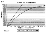
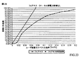
D1、D2及びD4に関する表4の結果は図18で与えられる初期マッピング(mapping)に関するものであり、他方、D3は図19のマッピングに関するものである。対応するフェアネス・プロットは図20〜図23に与えられる。フェアネス判定基準を満たすことが出来る結果の新しいセットが明示されるが、しかしながら、システムIoTは目標動作点4.5dBよりも高い。 The results in Table 4 for D1, D2 and D4 are for the initial mapping given in FIG. 18, while D3 is for the mapping of FIG. Corresponding fairness plots are given in FIGS. A new set of results that can meet the fairness criteria is specified, however, the system IoT is higher than the target operating point 4.5 dB.
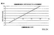
D1、D2及びD4に関する表4の結果は、図24で与えられる異なる初期マッピングに関するものであり、他方、D3は図25のマッピングに関するものである。図26〜図29は表4による初期PSD設定2に対する種々異なるフェアネス曲線を示す。これ等の条件に対する結果として得られたIoTはほぼ4.5dBであり、フェアネス判定基準が満たされ、そしてスループットはより高い。しかしながら、D1/D2/D4に関してはエッジ・スペクトル効率が遥かに低い。表4のD3に関する諸結果は表1に記載されたセル間電力制御ありの場合の諸結果よりも若干良い。セル間電力制御がある場合、セル当たりのIoTはかなり厳格に制御されるが、他方、セル間電力制御がない場合、IoTにはより大きな変動が存在する。セル間電力制御がない場合、ユーザ装置の配置次第で、異なるセルは異なる干渉電力を受ける可能性がある。これは図30〜図33で明示される。これらの図において、我々は、セル間電力制御あり及びなしの場合におけるセル間IoTのCDFを示す。 The results in Table 4 for D1, D2 and D4 are for the different initial mappings given in FIG. 24, while D3 is for the mapping of FIG. 26-29 show different fairness curves for the initial PSD setting 2 according to Table 4. The resulting IoT for these conditions is approximately 4.5 dB, fairness criteria are met, and throughput is higher. However, the edge spectral efficiency is much lower for D1 / D2 / D4. The results regarding D3 in Table 4 are slightly better than the results in the case of inter-cell power control described in Table 1. With inter-cell power control, IoT per cell is controlled fairly tight, while without inter-cell power control, there is a greater variation in IoT. Without inter-cell power control, different cells may receive different interference power depending on the user equipment placement. This is clearly shown in FIGS. In these figures, we show the inter-cell IoT CDF with and without inter-cell power control.
セル間電力制御の影響は、表5にまとめられるように、隣接セルからの負荷インジケータを有効化および無効化することによって評価される。
更に別の態様では、短時間IoTが、セル間電力制御あり及びなしの場合において、評価される。図34において、我々は、セル間電力制御あり及びなしの場合における、短時間IoTのCDFを提供する。該短時間IoTは1.5msec間で平均されるIoTと定義される。セル間電力制御なしの場合、該IoTのオーバーシュート(overshoot)はより高いことが理解され得る。 In yet another aspect, short time IoT is evaluated with and without intercell power control. In FIG. 34 we provide a short time IoT CDF with and without inter-cell power control. The short time IoT is defined as the IoT averaged over 1.5 msec. It can be seen that in the absence of inter-cell power control, the IoT overshoot is higher.
ソフトウェア実装の場合、本明細書記載の諸技術は本明細書記載の諸機能を実行するモジュール(例えば、手続き(procedure)、関数、等々)を用いて実装され得る。ソフトウェア・コードはメモリ・ユニット中に記憶されてプロセッサにより実行され得る。該メモリ・ユニットは該プロセッサ内部に或いは該プロセッサの外部に実装され得る。後者の場合、該メモリ・ユニットは公知の種々の手段を介して該プロセッサに通信で結合され得る。 For software implementation, the techniques described herein may be implemented using modules (eg, procedures, functions, etc.) that perform the functions described herein. The software code can be stored in a memory unit and executed by a processor. The memory unit may be implemented within the processor or external to the processor. In the latter case, the memory unit can be communicatively coupled to the processor via various known means.
上記に記載されてきた内容は1又は複数の実施形態の諸例を含む。無論、前述の諸実施形態を説明する目的のために、諸コンポーネント又は諸方法の考えられるあらゆる組合せを叙述することは不可能である。しかし、当業者は種々の実施形態の多数の更なる組合せと並べ替えが可能であることを理解する。従って、記載された諸実施形態は付帯クレームの精神と範囲に入る全てのその様な変更、修正および変形を包含するように意図される。更に、用語“含む”が詳細な説明または特許請求の範囲のいずれかで使用される限り、そのような用語は、“備える”が特許請求の範囲で移行語として使用されるときに解釈される場合の用語“備える”と同様に、包括的であることを意図されている。 What has been described above includes examples of one or more embodiments. Of course, it is impossible to describe every possible combination of components or methods for the purpose of describing the embodiments described above. However, those skilled in the art will appreciate that many additional combinations and permutations of various embodiments are possible. Accordingly, the described embodiments are intended to embrace all such alterations, modifications and variations that fall within the spirit and scope of the appended claims. Further, so long as the term “comprising” is used in either the detailed description or in the claims, such terms are to be interpreted when “comprising” is used as a transition term in the claims. Similar to the term “comprising” is intended to be inclusive.
Claims (13)
端末ノードとサービング・ノード間の及び端末ノードと隣接する非サービング・ノード間の伝搬路損失を決定することと、
前記端末ノードと前記隣接する非サービング・ノード間の前記決定された伝搬路損失を考慮して、前記端末ノードと前記サービング・ノード間の前記決定された伝搬路損失の一部を補償し、前記補償された前記端末ノードと前記サービング・ノード間の伝搬路損失に基づいて、目標受信信号対雑音比(SNR)を確立することと、
端末ノード使用開始時もしくは、前記補償された前記端末ノードと前記サービング・ノード間の伝搬路損失に基づいて確立された目標受信SNRが前記目標受信SNRの閾値目標帯を外れるときは、前記目標受信SNRを使用して前記端末ノードの送信電力スペクトル密度(PSD)を調整するように開ループPSD制御を使用することと、
前記補償された前記端末ノードと前記サービング・ノード間の伝搬路損失に基づいて確立された前記目標受信SNRが前記目標受信SNRの前記閾値目標帯内にあるときは、閉ループPSD制御に切り替えることと、
を備えた方法。 A method for facilitating inter-cell interference control in an OFDM system, comprising:
Determining propagation path loss between the terminal node and the serving node and between the terminal node and the adjacent non-serving node;
Taking into account the determined propagation path loss between the terminal node and the adjacent non-serving node, compensating for part of the determined propagation path loss between the terminal node and the serving node; Establishing a target received signal-to-noise ratio (SNR) based on the compensated path loss between the terminal node and the serving node ;
Terminal node used at the start or when the target received SNR, which is established based on the path loss between the compensated the terminal node and the serving node is out of the threshold target band of the target received SNR of the previous SL target Using open loop PSD control to adjust the transmit power spectral density (PSD) of the terminal node using received SNR;
Switching to closed-loop PSD control when the target received SNR established based on the compensated channel loss between the terminal node and the serving node is within the threshold target band of the target received SNR; ,
With a method.
Wassign(i)=ユーザ装置iに対して割り当てられる帯域幅≦Wtx(i)に基づいてユーザ装置に帯域幅を割り当て、
割り当てられた各ユーザ装置は、その送信PSDをΦtx(i)に設定して、
式
Passigned(i)=Φtx(i)・Wassign(i)≦Pmax(i)で与えられる電力レベルでデータを送信すること、
ここで、Φref(i)=ユーザ装置iに対する参照PSD、
Wref=参照帯域幅、
Φtx(i)=ユーザ装置iに対する送信PSD、
Δpsd=参照PSD増分(dB)、
Wtx(i)=ユーザ装置iにとって対応可能な帯域幅
であり、
前記参照PSDは、
前記ユーザ装置は、
Δ(i)=Δpsd−f(Li)
前記送信PSDは
を備えた、請求項1に記載の方法。 Assign bandwidth to the user equipment based on the formula W assign (i) = bandwidth assigned to user equipment i ≦ W tx (i)
Each assigned user equipment sets its transmission PSD to Φ tx (i),
Transmitting the data by the formula P assigned (i) = Φ tx (i) · W assign (i) ≦ P max (i) at given power level,
Where Φ ref (i) = reference PSD for user equipment i,
W ref = reference bandwidth,
Φ tx (i) = transmit PSD for user equipment i,
Δ psd = reference PSD increment (dB),
W tx (i) = bandwidth that can be supported by user equipment i,
The reference PSD is
The user equipment is
Δ (i) = Δ psd −f (L i )
The transmission PSD is
The method of claim 1 comprising:
端末ノードとサービング・ノード間の及び端末ノードと隣接する非サービング・ノード間の伝搬路損失を決定するための手段と、
前記端末ノードと前記隣接する非サービング・ノード間の前記決定された伝搬路損失を考慮して、前記端末ノードと前記サービング・ノード間の前記決定された伝搬路損失の一部を補償し、前記補償された前記端末ノードと前記サービング・ノード間の伝搬路損失に基づいて、目標受信信号対雑音比(SNR)を確立するための手段と、
端末ノード使用開始時もしくは、前記補償された前記端末ノードと前記サービング・ノード間の伝搬路損失に基づいて確立された目標受信SNRが前記目標受信SNRの閾値目標帯を外れるときは、前記目標受信SNRを使用して前記端末ノードの送信電力スペクトル密度(PSD)を調整するように開ループPSD制御を使用するための手段と、
前記補償された前記端末ノードと前記サービング・ノード間の伝搬路損失に基づいて確立された前記目標受信SNRが前記目標受信SNRの前記閾値目標帯内にあるときは、閉ループPSD制御に切り替えるための手段と、
を備えたシステム。 A system that facilitates inter-cell interference control in an OFDM system,
Means for determining propagation path loss between a terminal node and a serving node and between a terminal node and a non-serving node adjacent to the terminal node;
Taking into account the determined propagation path loss between the terminal node and the adjacent non-serving node, compensating for part of the determined propagation path loss between the terminal node and the serving node; Means for establishing a target received signal-to-noise ratio (SNR) based on the compensated path loss between the terminal node and the serving node ;
Terminal node used at the start or when the target received SNR, which is established based on the path loss between the compensated the terminal node and the serving node is out of the threshold target band of the target received SNR of the previous SL target Means for using open loop PSD control to adjust the transmit power spectral density (PSD) of the terminal node using received SNR;
When the target reception SNR established based on the compensated channel loss between the terminal node and the serving node is within the threshold target band of the target reception SNR, for switching to closed loop PSD control Means,
With system.
Applications Claiming Priority (3)
| Application Number | Priority Date | Filing Date | Title |
|---|---|---|---|
| US86392806P | 2006-11-01 | 2006-11-01 | |
| US60/863,928 | 2006-11-01 | ||
| PCT/US2007/083260 WO2008055247A1 (en) | 2006-11-01 | 2007-10-31 | Inter-cell power control for interference management |
Publications (2)
| Publication Number | Publication Date |
|---|---|
| JP2010508787A JP2010508787A (en) | 2010-03-18 |
| JP5323712B2 true JP5323712B2 (en) | 2013-10-23 |
Family
ID=38991314
Family Applications (1)
| Application Number | Title | Priority Date | Filing Date |
|---|---|---|---|
| JP2009535456A Expired - Fee Related JP5323712B2 (en) | 2006-11-01 | 2007-10-31 | Inter-cell power control for interference management |
Country Status (10)
| Country | Link |
|---|---|
| US (1) | US8285216B2 (en) |
| EP (1) | EP2092662B1 (en) |
| JP (1) | JP5323712B2 (en) |
| KR (1) | KR101086604B1 (en) |
| CN (1) | CN101536349B (en) |
| BR (1) | BRPI0717886A2 (en) |
| CA (1) | CA2666215A1 (en) |
| RU (1) | RU2414058C2 (en) |
| TW (1) | TW200838202A (en) |
| WO (1) | WO2008055247A1 (en) |
Families Citing this family (43)
| Publication number | Priority date | Publication date | Assignee | Title |
|---|---|---|---|---|
| US6961595B2 (en) * | 2002-08-08 | 2005-11-01 | Flarion Technologies, Inc. | Methods and apparatus for operating mobile nodes in multiple states |
| US8190163B2 (en) * | 2002-08-08 | 2012-05-29 | Qualcomm Incorporated | Methods and apparatus of enhanced coding in multi-user communication systems |
| US7363039B2 (en) | 2002-08-08 | 2008-04-22 | Qualcomm Incorporated | Method of creating and utilizing diversity in multiple carrier communication system |
| WO2004075470A2 (en) * | 2003-02-19 | 2004-09-02 | Flarion Technologies, Inc. | Controlled superposition coding in multi-user communication systems |
| US8593932B2 (en) * | 2003-05-16 | 2013-11-26 | Qualcomm Incorporated | Efficient signal transmission methods and apparatus using a shared transmission resource |
| US7925291B2 (en) * | 2003-08-13 | 2011-04-12 | Qualcomm Incorporated | User specific downlink power control channel Q-bit |
| US20080045259A1 (en) * | 2006-08-15 | 2008-02-21 | Zukang Shen | Cellular Uplink Power Control with Inter-NodeB Power Control Information Exchange |
| US8755313B2 (en) | 2007-01-11 | 2014-06-17 | Qualcomm Incorporated | Using DTX and DRX in a wireless communication system |
| US9295003B2 (en) * | 2007-03-19 | 2016-03-22 | Apple Inc. | Resource allocation in a communication system |
| JP5232224B2 (en) * | 2007-06-20 | 2013-07-10 | ノキア シーメンス ネットワークス オサケ ユキチュア | How to report power headroom |
| US8577304B2 (en) * | 2007-10-31 | 2013-11-05 | Icera, Inc. | Synchronous CDMA communication system |
| US8165098B2 (en) * | 2008-02-11 | 2012-04-24 | Mitsubishi Electric Research Laboratories, Inc. | Method for allocating resources in cell-edge bands of OFDMA networks |
| US8548383B2 (en) | 2008-08-27 | 2013-10-01 | Qualcomm Incorporated | Power spectrum density control for wireless communications |
| KR101571563B1 (en) * | 2008-09-24 | 2015-11-25 | 엘지전자 주식회사 | Method for controlling uplink power for multi-cell cooperative radio communication system and terminal supporting the method |
| US8982750B2 (en) * | 2009-01-16 | 2015-03-17 | Qualcomm Incorporated | Method and apparatus for transmitting overload indicator over the air |
| EP2224659B1 (en) | 2009-02-26 | 2011-04-27 | Alcatel Lucent | Power manageable optical OFDM transponder |
| KR101530201B1 (en) * | 2009-03-03 | 2015-06-19 | 삼성전자주식회사 | A signal transmission system for transmitting a signal by applying an interference control method and / or a transmission power control method and a method thereof |
| WO2011004947A1 (en) * | 2009-07-10 | 2011-01-13 | Lg Electronics Inc. | Method of optimizing comp zone for joint processing mode |
| US8976729B2 (en) * | 2009-08-19 | 2015-03-10 | Qualcomm Incorporated | Maximum power spectral density reporting in response to overload indications |
| US8559325B2 (en) * | 2009-09-15 | 2013-10-15 | Qualcomm Incorporated | Systems and methods for over the air load indicator for wireless scheduling |
| US8909269B2 (en) * | 2009-10-05 | 2014-12-09 | Nokia Siemens Networks Oy | Interference control |
| JP5475894B2 (en) * | 2009-12-29 | 2014-04-16 | テレフオンアクチーボラゲット エル エム エリクソン(パブル) | Wireless system output control |
| US8868091B2 (en) | 2010-01-18 | 2014-10-21 | Qualcomm Incorporated | Methods and apparatus for facilitating inter-cell interference coordination via over the air load indicator and relative narrowband transmit power |
| KR101593238B1 (en) * | 2010-01-20 | 2016-02-12 | 삼성전자주식회사 | Apparatus and method for controlling transmission power in wireless communication system |
| WO2011088619A1 (en) * | 2010-01-22 | 2011-07-28 | Nokia Corporation | Cellular control sensing for multi-cell device-to-device interference control |
| CN102149111B (en) * | 2010-02-08 | 2015-09-16 | 中兴通讯股份有限公司 | A kind of neighbor cell information management method and system |
| US8571482B2 (en) * | 2010-09-11 | 2013-10-29 | Nokia Corporation | Dynamic autonomous resource allocation and channel access in cellular System Uplink |
| CN102573028A (en) * | 2010-12-16 | 2012-07-11 | 中兴通讯股份有限公司 | Open loop power controlling method and system |
| CN103518405A (en) * | 2011-03-17 | 2014-01-15 | 诺基亚西门子网络公司 | Method and apparatus for determining transmission power |
| US9832665B2 (en) * | 2011-04-13 | 2017-11-28 | Lg Electronics Inc. | Method for sending and receiving signals for alleviating inter-cell interference in a wireless communication system and a device therefor |
| WO2012167425A1 (en) * | 2011-06-08 | 2012-12-13 | Nokia Siemens Networks Oy | Transmission power |
| US8848698B2 (en) * | 2011-10-22 | 2014-09-30 | Lg Electronics Inc. | Scheduling method in multiple access system and apparatus using the same |
| AU2013381337B2 (en) * | 2013-04-25 | 2016-02-25 | Intel Corporation | Millimeter-wave communication device and method for intelligent control of transmit power and power density |
| KR20150047801A (en) * | 2013-10-25 | 2015-05-06 | 삼성전자주식회사 | Method and apparatus for offload traffic in wireless communication system |
| WO2015094026A1 (en) | 2013-12-16 | 2015-06-25 | Telefonaktiebolaget L M Ericsson (Publ) | Method and apparatus for uplink and/or downlink power control in a radio communication network |
| CN104837190B (en) * | 2014-02-07 | 2018-09-14 | 中国电信股份有限公司 | For realizing the method and apparatus of adaptive open-loop power control |
| US9673887B1 (en) * | 2014-03-21 | 2017-06-06 | Rockwell Collins, Inc. | Self-calibration of a communications device for transmit power level control |
| US10327212B2 (en) * | 2014-05-06 | 2019-06-18 | Telefonaktiebolaget Lm Ericsson (Publ) | Uplink power control in heterogeneous networks |
| DE102015110160B4 (en) * | 2015-06-24 | 2018-03-29 | Intel IP Corporation | A multicast data transmission system and method of operating the same |
| CN111466140B (en) * | 2017-12-25 | 2021-12-03 | 华为技术有限公司 | Parameter adjusting method and related equipment |
| WO2019158123A1 (en) * | 2018-02-16 | 2019-08-22 | Telefonaktiebolaget Lm Ericsson (Publ) | Method and system for scheduled uplink transmission to resolve channel interference in a wireless network using a coordination indicator |
| US11057882B1 (en) * | 2018-04-03 | 2021-07-06 | T-Mobile Innovations Llc | Systems and methods for dynamically setting frame configuration in a wireless network |
| US11582699B2 (en) | 2021-02-15 | 2023-02-14 | Harris Global Communications, Inc. | Mobile ad hoc network providing power control and associated methods |
Family Cites Families (17)
| Publication number | Priority date | Publication date | Assignee | Title |
|---|---|---|---|---|
| JPH1065604A (en) * | 1996-08-23 | 1998-03-06 | Sony Corp | Communication method, base station and terminal equipment |
| US6377809B1 (en) | 1997-09-16 | 2002-04-23 | Qualcomm Incorporated | Channel structure for communication systems |
| JP2000151500A (en) | 1998-11-05 | 2000-05-30 | Nec Saitama Ltd | Cdma transmission power control method and its system |
| US6628956B2 (en) * | 1999-03-15 | 2003-09-30 | Telefonaktiebolaget Lm Ericsson (Publ) | Adaptive power control in a radio communications systems |
| JP3360053B2 (en) * | 1999-11-19 | 2002-12-24 | 埼玉日本電気株式会社 | Mobile communication terminal |
| US6600772B1 (en) * | 2000-03-21 | 2003-07-29 | Interdigital Communications Corporation | Combined closed loop/open loop power control in a time division duplex communication system |
| US6707862B1 (en) * | 2000-03-21 | 2004-03-16 | Denso Corporation | Predictive data rate control in wireless transmitters |
| JP3456197B2 (en) | 2000-08-30 | 2003-10-14 | 日本電気株式会社 | Transmission power storage control circuit and method |
| US6587697B2 (en) | 2001-05-14 | 2003-07-01 | Interdigital Technology Corporation | Common control channel uplink power control for adaptive modulation and coding techniques |
| JP4256158B2 (en) | 2002-12-26 | 2009-04-22 | パナソニック株式会社 | Wireless communication apparatus and wireless communication method |
| US7979078B2 (en) | 2003-06-16 | 2011-07-12 | Qualcomm Incorporated | Apparatus, system, and method for managing reverse link communication resources in a distributed communication system |
| JP4107432B2 (en) | 2004-03-03 | 2008-06-25 | 独立行政法人電子航法研究所 | Mobile station, mobile station side communication control method, base station, base station communication control method, and communication system |
| US8452316B2 (en) | 2004-06-18 | 2013-05-28 | Qualcomm Incorporated | Power control for a wireless communication system utilizing orthogonal multiplexing |
| ATE442022T1 (en) | 2004-07-13 | 2009-09-15 | Alcatel Lucent | METHOD FOR TERMINAL-SUPPORTED INTERFERENCE CONTROL IN A MULTI-CARRIER MOBILE COMMUNICATIONS SYSTEM |
| KR100725773B1 (en) * | 2004-08-20 | 2007-06-08 | 삼성전자주식회사 | Apparatus and method for adaptively changing uplink power control scheme according to terminal state in time division duplex mobile communication system |
| US7205842B2 (en) * | 2005-01-13 | 2007-04-17 | Telefonaktiebolaget Lm Ericsson (Publ) | Continuous alternating closed-open loop power control |
| TWI317580B (en) | 2005-03-15 | 2009-11-21 | Qualcomm Inc | Multiple other sector information combining for power control in a wireless communication system |
-
2007
- 2007-10-31 JP JP2009535456A patent/JP5323712B2/en not_active Expired - Fee Related
- 2007-10-31 RU RU2009120508/09A patent/RU2414058C2/en active
- 2007-10-31 US US12/443,969 patent/US8285216B2/en active Active
- 2007-10-31 WO PCT/US2007/083260 patent/WO2008055247A1/en active Application Filing
- 2007-10-31 CA CA002666215A patent/CA2666215A1/en not_active Abandoned
- 2007-10-31 BR BRPI0717886-7A patent/BRPI0717886A2/en not_active IP Right Cessation
- 2007-10-31 EP EP07844791.9A patent/EP2092662B1/en active Active
- 2007-10-31 KR KR1020097010948A patent/KR101086604B1/en active IP Right Grant
- 2007-10-31 CN CN2007800406475A patent/CN101536349B/en active Active
- 2007-11-01 TW TW096141263A patent/TW200838202A/en unknown
Also Published As
| Publication number | Publication date |
|---|---|
| RU2009120508A (en) | 2010-12-10 |
| KR101086604B1 (en) | 2011-11-23 |
| KR20090075876A (en) | 2009-07-09 |
| RU2414058C2 (en) | 2011-03-10 |
| JP2010508787A (en) | 2010-03-18 |
| CA2666215A1 (en) | 2008-05-08 |
| US8285216B2 (en) | 2012-10-09 |
| US20100029212A1 (en) | 2010-02-04 |
| WO2008055247A1 (en) | 2008-05-08 |
| CN101536349A (en) | 2009-09-16 |
| EP2092662A1 (en) | 2009-08-26 |
| CN101536349B (en) | 2013-02-13 |
| EP2092662B1 (en) | 2016-09-28 |
| TW200838202A (en) | 2008-09-16 |
| BRPI0717886A2 (en) | 2013-11-05 |
Similar Documents
| Publication | Publication Date | Title |
|---|---|---|
| JP5323712B2 (en) | Inter-cell power control for interference management | |
| JP7157845B2 (en) | Power control of sounding reference signals for multiple-input multiple-output wireless systems | |
| US9960881B2 (en) | System and method for modulation and coding scheme adaptation and power control in a relay network | |
| Zhang et al. | Weighted sum-rate maximization in multi-cell networks via coordinated scheduling and discrete power control | |
| US8340593B2 (en) | Techniques to control uplink power | |
| KR101079002B1 (en) | Reverse link traffic power control for lbc fdd | |
| CN101869000B (en) | Opportunistic uplink scheduling | |
| US20180132189A1 (en) | Techniques for adjusting transmit power in wireless communications | |
| US9668266B2 (en) | Interference control in HETNETs | |
| US8964664B2 (en) | System and method for association and uplink adaptation in a relay network | |
| US8433359B2 (en) | Uplink power control scheme | |
| US10420037B2 (en) | Communication control method, communication system, and management server | |
| JP5630906B2 (en) | Transmission power control apparatus and method in wireless communication system | |
| WO2018059264A1 (en) | Method and device for scheduling transmissions in wireless communication system | |
| CN114554599A (en) | PDCCH resource allocation method, device and network equipment | |
| WO2017201685A1 (en) | Method and apparatus for device to device communication | |
| CN108702242A (en) | network node and its method | |
| WO2017045695A1 (en) | Method, system and apparatus for switching between d2d and cellular communications | |
| WO2014114471A1 (en) | Protecting ul control channels in dynamic/flexible tdd | |
| JP7634742B2 (en) | Power control of sounding reference signals for multiple-input multiple-output wireless systems - Patents.com | |
| WO2025010599A1 (en) | Power reduction for communication systems | |
| WO2024231460A1 (en) | System and apparatus for controlling congestion in sidelink positioning and a method in association thereto | |
| WO2024255829A1 (en) | Method and apparatus used in node for wireless communication |
Legal Events
| Date | Code | Title | Description |
|---|---|---|---|
| A977 | Report on retrieval |
Free format text: JAPANESE INTERMEDIATE CODE: A971007 Effective date: 20111227 |
|
| A131 | Notification of reasons for refusal |
Free format text: JAPANESE INTERMEDIATE CODE: A131 Effective date: 20120110 |
|
| A521 | Request for written amendment filed |
Free format text: JAPANESE INTERMEDIATE CODE: A523 Effective date: 20120405 |
|
| A131 | Notification of reasons for refusal |
Free format text: JAPANESE INTERMEDIATE CODE: A131 Effective date: 20120515 |
|
| A601 | Written request for extension of time |
Free format text: JAPANESE INTERMEDIATE CODE: A601 Effective date: 20120815 |
|
| A602 | Written permission of extension of time |
Free format text: JAPANESE INTERMEDIATE CODE: A602 Effective date: 20120822 |
|
| A521 | Request for written amendment filed |
Free format text: JAPANESE INTERMEDIATE CODE: A523 Effective date: 20121109 |
|
| TRDD | Decision of grant or rejection written | ||
| A01 | Written decision to grant a patent or to grant a registration (utility model) |
Free format text: JAPANESE INTERMEDIATE CODE: A01 Effective date: 20130618 |
|
| A61 | First payment of annual fees (during grant procedure) |
Free format text: JAPANESE INTERMEDIATE CODE: A61 Effective date: 20130717 |
|
| R150 | Certificate of patent or registration of utility model |
Ref document number: 5323712 Country of ref document: JP Free format text: JAPANESE INTERMEDIATE CODE: R150 Free format text: JAPANESE INTERMEDIATE CODE: R150 |
|
| R250 | Receipt of annual fees |
Free format text: JAPANESE INTERMEDIATE CODE: R250 |
|
| R250 | Receipt of annual fees |
Free format text: JAPANESE INTERMEDIATE CODE: R250 |
|
| R250 | Receipt of annual fees |
Free format text: JAPANESE INTERMEDIATE CODE: R250 |
|
| R250 | Receipt of annual fees |
Free format text: JAPANESE INTERMEDIATE CODE: R250 |
|
| R250 | Receipt of annual fees |
Free format text: JAPANESE INTERMEDIATE CODE: R250 |
|
| R250 | Receipt of annual fees |
Free format text: JAPANESE INTERMEDIATE CODE: R250 |
|
| R250 | Receipt of annual fees |
Free format text: JAPANESE INTERMEDIATE CODE: R250 |
|
| LAPS | Cancellation because of no payment of annual fees |