JP5322593B2 - Focus adjustment apparatus and method - Google Patents
Focus adjustment apparatus and method Download PDFInfo
- Publication number
- JP5322593B2 JP5322593B2 JP2008287944A JP2008287944A JP5322593B2 JP 5322593 B2 JP5322593 B2 JP 5322593B2 JP 2008287944 A JP2008287944 A JP 2008287944A JP 2008287944 A JP2008287944 A JP 2008287944A JP 5322593 B2 JP5322593 B2 JP 5322593B2
- Authority
- JP
- Japan
- Prior art keywords
- focus
- phase difference
- subject
- face
- focus lens
- Prior art date
- Legal status (The legal status is an assumption and is not a legal conclusion. Google has not performed a legal analysis and makes no representation as to the accuracy of the status listed.)
- Expired - Fee Related
Links
Images


Landscapes
- Automatic Focus Adjustment (AREA)
- Studio Devices (AREA)
- Focusing (AREA)
Abstract
Description
本発明は、ビデオカメラ等の撮像装置に用いられる焦点調節方法及び方法に関し、特に顔検出機能を利用して、コントラストAFと位相差AFとを併用する焦点調節方法及び方法に関する。 The present invention relates to a focus adjustment method and method used for an imaging apparatus such as a video camera, and more particularly to a focus adjustment method and method using both a contrast AF and a phase difference AF using a face detection function.
ビデオカメラ等の撮像装置に搭載されるオートフォーカス(AF)方式としては、コントラストAF方式が一般的に用いられている。コントラストAF方式では、撮像素子を用いて得られた映像信号のから高周波成分を抽出して、焦点状態を示す信号である、いわゆるAF評価値信号を生成し、このAF評価値信号が最大になるようにフォーカスレンズの位置を制御する。 A contrast AF method is generally used as an autofocus (AF) method mounted on an imaging apparatus such as a video camera. In the contrast AF method, a high-frequency component is extracted from a video signal obtained using an image sensor, and a so-called AF evaluation value signal, which is a signal indicating a focus state, is generated, and this AF evaluation value signal is maximized. In this way, the position of the focus lens is controlled.
また、このようなコントラストAF方式と、いわゆる外測位相差検出(以下「位相差AF」と呼ぶ。)方式とを組み合わせた、いわゆるハイブリッドAF方式を採用した撮像装置も提案されている(例えば、特許文献1参照)。外測位相差AF方式は、撮像光学系を通らない光を2つの光束に分割してそれぞれセンサにより受光し、被写体までの距離に応じて変化する受光した光の位相差に基づいて、フォーカスレンズの位置を制御するものである。ハイブリッドAF方式では、コントラストAF方式による高精度の合焦性能と、外測位相差AF方式による高速な合焦性能とを併せ持つことができる。 There has also been proposed an imaging apparatus that employs a so-called hybrid AF system that combines such a contrast AF system with a so-called external phase difference detection (hereinafter referred to as “phase difference AF”) system (for example, a patent). Reference 1). In the external phase difference AF method, light that does not pass through the imaging optical system is divided into two light beams, which are respectively received by sensors, and based on the phase difference of the received light that changes according to the distance to the subject, The position is controlled. The hybrid AF method can have both high-precision focusing performance by the contrast AF method and high-speed focusing performance by the external measurement phase difference AF method.
一方で、顔検出機能を搭載したカメラの開発も活発に行われており、例えば、特許文献2にあるように、検出された顔にフォーカスを合わせるように、検出された顔の領域に基づいてAF検出領域を指定する技術も紹介されている。 On the other hand, a camera equipped with a face detection function is also actively developed. For example, as disclosed in Patent Document 2, based on the detected face area so as to focus on the detected face. A technique for designating an AF detection area is also introduced.
検出された顔の領域にフォーカスを合わせる顔優先AFでは、顔が写っている画像では顔にフォーカスを合わせるようにAF動作が働くが、顔が新たに検出された直後や、逆に顔が検出されなくなった直後にはAF動作が不安定になり得る。特に位相差AF方式では、被写体までの距離に応じて変化する被写体像の位相差をセンサによって直接検出し、その検出した位相差から求めた合焦位置にフォーカスレンズを移動させるので、被写体に素早く反応して、高速でAF動作を行うことができる。しかしながら、撮像した画像から顔検出するには各種の画像処理を行うため少なからず時間がかかり、位相差AFにかかる数倍以上の時間後に、撮像した画像内に顔があるのか無いのか、顔があるならばどの位置にあるのか、といった顔の検出結果が分かる。 In face-priority AF that focuses on the detected face area, the AF operation works to focus on the face in an image that contains a face, but the face is detected immediately after a new face is detected or conversely. Immediately after being stopped, the AF operation may become unstable. In particular, in the phase difference AF method, the phase difference of the subject image that changes according to the distance to the subject is directly detected by the sensor, and the focus lens is moved to the in-focus position obtained from the detected phase difference, so that the subject can be quickly moved. In response, the AF operation can be performed at high speed. However, detecting a face from the captured image takes various time since various image processing is performed, and after several times or more required for the phase difference AF, whether the face is present in the captured image or not is detected. If there is, it is possible to know the detection result of the face such as where it is.
このような時間遅延のある中で位相差AF1を伴うハイブリッドAF方式を用いて顔優先AFを行うと、例えば、顔が検出されていない状態においてカメラをパンニングさせて画角を変更していった場合に、次のような問題が発生する。まず、人(顔)ではない被写体が位相差AFの検出領域にあり、更に、位相差AFの検出領域外の、被写体までの距離とは異なる距離に人(顔)がある場合を想定する。この場合、先ず、顔検出を行っている間に位相差AFによって検出領域内の被写体に焦点が合うようにAF動作する。そして顔検出により少しディレイのあった後に、顔と判定された領域に対してコントラストAFなどの他方式によって顔に対してフォーカス動作が行われる。このような動作はユーザーからすると、顔の検出前後において、フォーカスのハンチングが起こるように見えて、非常に不愉快なものであるという問題点があった。 When face priority AF is performed using the hybrid AF method with phase difference AF1 in such a time delay, for example, the angle of view is changed by panning the camera in a state where no face is detected. If the following problem occurs. First, it is assumed that a subject that is not a person (face) is in the phase difference AF detection area, and that the person (face) is outside the phase difference AF detection area at a distance different from the distance to the subject. In this case, first, during the face detection, the AF operation is performed so that the subject in the detection area is focused by the phase difference AF. After a slight delay due to face detection, the focus operation is performed on the face by another method such as contrast AF for the area determined to be a face. From the viewpoint of the user, such an operation has a problem in that it appears that focus hunting occurs before and after face detection, which is very unpleasant.
本発明は上記問題点を鑑みてなされたものであり、位相差AFを伴うハイブリッドAF方式を用いて、予め設定された被写体を検出して、検出した被写体にフォーカスを合わせる場合に、ハンチングを回避することを目的とする。 The present invention has been made in view of the above problems, and avoids hunting when a preset subject is detected using the hybrid AF method with phase difference AF and the detected subject is focused. The purpose is to do.
また、被写体を検出して、検出した被写体にフォーカスを合わせる場合に、より素早くフォーカスを合わせることができるようにすることを別の目的とする。 Another object is to enable quicker focusing when a subject is detected and the detected subject is focused.
上記目的を達成するために、本発明の焦点調節装置は、撮像素子から入力される入力画像のコントラストに基づいて、合焦位置の方向にフォーカスレンズを駆動するように制御する第1の焦点調節方式と、被写体からの光により形成された一対の像の位相差に基づいて、前記フォーカスレンズを合焦位置に駆動するように制御する第2の焦点調節方式と、を選択的に用いて合焦制御する焦点調節手段と、前記撮像素子から入力される入力画像から求められた被写体検出位置と前記位相差の検出領域である位相差検出領域の位置関係を判定する判定手段とを有し、前記焦点調節手段は、前記判定手段にて前記位相差検出領域の上側に前記被写体検出位置があると判定され、前記入力画像における前記被写体の大きさが所定値以上である場合、前記第2の焦点調節方式により前記フォーカスレンズを駆動し、前記判定手段にて前記位相差検出領域の上側に前記被写体検出位置があると判定され、前記入力画像における前記被写体の大きさが所定値よりも小さい場合、前記第1の焦点調節方式により前記フォーカスレンズを駆動し、前記判定手段にて前記位相差検出領域の下側に前記被写体検出位置があると判定された場合、前記第1の焦点調節方式により前記フォーカスレンズを駆動する。 To achieve the above object, the focus adjustment apparatus of the present invention controls the first focus adjustment for controlling the focus lens to be driven in the direction of the in-focus position based on the contrast of the input image input from the image sensor. And a second focus adjustment method that controls the focus lens to be driven to the in-focus position based on the phase difference between a pair of images formed by light from the subject. Focus adjustment means for controlling the focus, and determination means for determining the positional relationship between the subject detection position obtained from the input image input from the image sensor and the phase difference detection area which is the phase difference detection area, said focusing means, the is determined in the determination means is the subject detection position above the phase difference detection area, when the size of the subject in the input image is a predetermined value or more, before The second focusing system to drive the focus lens, the is determined in the determination means is the subject detection position above the phase difference detection area, the size of the subject in the input image than the predetermined value Is smaller, the focus lens is driven by the first focus adjustment method, and the first focus is determined when the determination means determines that the subject detection position is below the phase difference detection region. The focus lens is driven by an adjustment method.
また、撮像素子から入力される入力画像のコントラストに基づいて、合焦位置の方向にフォーカスレンズを駆動するように制御する第1の焦点調節方式と、被写体からの光により形成された一対の像の位相差に基づいて、前記フォーカスレンズを合焦位置に駆動するように制御する第2の焦点調節方式と、を選択的に用いて合焦制御する本発明の焦点調節方法は、判定手段が、前記撮像素子から入力される入力画像から求められた被写体検出位置と前記位相差の検出領域である位相差検出領域の位置関係を判定する判定工程と、焦点調節手段が、前記判定工程にて前記位相差検出領域の上側に前記被写体検出位置があると判定され、前記入力画像における前記被写体の大きさが所定値以上である場合、前記第2の焦点調節方式により前記フォーカスレンズを駆動し、前記判定工程にて前記位相差検出領域の上側に前記被写体検出位置があると判定され、前記入力画像における前記被写体の大きさが所定値よりも小さい場合、前記第1の焦点調節方式により前記フォーカスレンズを駆動し、前記判定工程にて前記位相差検出領域の下側に前記被写体検出位置があると判定された場合、前記第1の焦点調節方式により前記フォーカスレンズを駆動する駆動工程とを有する。 Also, a first focus adjustment method for controlling the focus lens to be driven in the direction of the in-focus position based on the contrast of the input image input from the image sensor, and a pair of images formed by light from the subject The focus adjustment method of the present invention that selectively uses the second focus adjustment method that controls the focus lens to be driven to the in-focus position based on the phase difference of A determination step of determining a positional relationship between a subject detection position obtained from an input image input from the image sensor and a phase difference detection region that is the detection region of the phase difference; and a focus adjustment unit in the determination step it is determined that there is the object detected position on an upper side of the phase difference detection area, when the size of the subject in the input image is a predetermined value or more, the by the second focusing method follower Drives Kasurenzu, the determination step in the subject detection position above the phase difference detection area is determined that, when the size of the subject in the input image is smaller than the predetermined value, the first focus of The focus lens is driven by an adjustment method, and when it is determined in the determination step that the subject detection position is below the phase difference detection region, the focus lens is driven by the first focus adjustment method. And a driving process.
本発明によれば、位相差AFを伴うハイブリッドAF方式を用いて、予め設定された被写体を検出して、検出した被写体にフォーカスを合わせる場合に、ハンチングを回避することができる。 According to the present invention, it is possible to avoid hunting when a preset subject is detected using the hybrid AF method with phase difference AF and the detected subject is focused.
また、被写体を検出して、検出した被写体にフォーカスを合わせる場合に、より素早くフォーカスを合わせることができる。 Further, when the subject is detected and the detected subject is focused, the focus can be adjusted more quickly.
以下、添付図面を参照して本発明を実施するための最良の形態を詳細に説明する。 The best mode for carrying out the present invention will be described below in detail with reference to the accompanying drawings.
<第1の実施形態>
●装置構成
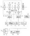
図1は、本発明の焦点調節装置を備える第1の実施形態における撮像装置として、ビデオカメラの構成を示すブロック図である。
<First Embodiment>
Apparatus Configuration FIG. 1 is a block diagram showing a configuration of a video camera as an imaging apparatus according to the first embodiment including the focus adjustment apparatus of the present invention.
同図において、100はレンズユニットであり、物体側(被写体側)から順に、固定レンズ101、変倍レンズ102、絞り103、固定レンズ104及びフォーカスレンズ105により構成される撮像光学系を収容している。108は変倍レンズ102、絞り103及びフォーカスレンズ105の位置を検出する位置エンコーダである。
In the figure, reference numeral 100 denotes a lens unit that houses an imaging optical system including a
変倍レンズ102はズームモータ106により光軸方向に駆動され、フォーカスレンズ105はフォーカスモータ107により光軸方向に駆動される。これらズームモータ106及びフォーカスモータ107はそれぞれ、ズーム駆動回路120及びフォーカス駆動回路121からの駆動信号を受けて動作する。
The
109はCCDセンサ、CMOSセンサ等により構成された撮像素子である。撮像素子109は、撮像光学系に入射した光によって形成された、撮像範囲内の物体の像を光電変換する。撮像信号処理回路119は、撮像素子109からの出力信号に対して、増幅処理、ガンマ補正処理、ホワイトバランス処理等の各種信号処理を施し、所定の映像フォーマットの画像信号に変換する。得られた画像信号は、モニタディスプレイ114に出力されたり、半導体メモリ、光ディスク、ハードディスク等の画像記録用メディア116に記録されたりする。
110はメインCPUで、ビデオカメラの各種動作や機能を制御する。操作スイッチ群115には、電源スイッチや、録画動作や再生動作を開始及び停止させるスイッチ、ビデオカメラの動作モードを選択するためのスイッチ、変倍レンズ102のズーム状態を変化させるズームスイッチ等が設けられている。また、後述するAF動作モードを選択するために用いられるスイッチも設けられている。これらのスイッチが操作されると、フラッシュメモリ113に格納されていたコンピュータプログラムの一部がRAM112にロードされ、メインCPU110はRAM112にロードされたプログラムに従って各部の動作を制御する。
A
111は顔検出処理回路であり、撮像信号処理回路119から出力される画像信号に対して画像処理を行い、顔の有無判定を行い、顔がある場合には画像内における顔の位置や顔の大きさ等を検出する。顔検出処理回路111が行う画像処理には、元の画像信号を演算のためにサイズを小さくするリサイズ処理や、顔の輪郭検出処理、顔であることの信頼度判定処理等が含まれる。このため、後述するように画像信号を受け取ってから、検出結果が出るまでに、数十ms〜数百msの時間がかかる。
A face
一方、131は位相差AF用のラインセンサであり、複数の受光素子が一列に並べられて構成されている。ラインセンサ131には、被写体からの光が撮像光学系とは別に設けられた外測位相差AF用の結像レンズ130を通って、すなわちレンズユニット100を通らずに到達する。なお、レンズユニット100を透過した光を二分して、撮像素子109とラインセンサ131とにそれぞれ光を振り分けることの可能な光学素子を光路に挿入することで、カメラ内部に構成することもできる。
On the other hand, 131 is a line sensor for phase difference AF, and a plurality of light receiving elements are arranged in a line. The light from the subject reaches the
●位相差AF方式(第2の焦点調節方式)の原理
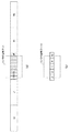
本第1の実施形態におけるラインセンサ131は、図2に示すように、結像レンズ130の光軸上の位置を中心として左右に合計200個の受光素子が並べられて構成されている。また、図2(a)、(b)に示すように、ズーム倍率に応じて、カメラの画角に対する、ラインセンサ131の受光領域の大きさの割合は変化する。なお、図2では、中心の受光エリアCと、その左右に配置された受光エリアL1、L2、R1、R2とに分けて示している。各受光エリアは40個ずつの受光素子で構成されている。
● Principle of Phase Difference AF Method (Second Focus Adjustment Method) As shown in FIG. 2, the
このように200個の受光素子により構成されたラインセンサ131は、左右に2つ設けられている。そして、これら2つのラインセンサ131において対応する受光エリアに形成された1対の画像のずれ量(位相差)を検出する。このずれ量は、被写体までの距離に応じて変化するため、ラインセンサ131から出力される信号は、被写体(又は物体)までの距離に応じた信号である。なお、ラインセンサ131を構成する受光素子の数は、200個に限られるものではないことは言うまでもない。
In this way, two
図3に、ラインセンサを用いた位相差AF方式の原理を示す。図3において、201は被写体、202は第1の結像レンズ、203は第1のラインセンサである。204は第2の結像レンズ、205は第2のラインセンサである。これら一対の第1及び第2の結像レンズ202、204は図1に示した結像レンズ130に、一対の第1及び第2のラインセンサ203、205は図1に示したラインセンサ131にそれぞれ相当する。第1及び第2のラインセンサ203、205は、基線長Bだけ互いに離れて設置されている。被写体201からの光のうち、第1の結像レンズ202を通った光は、第1のラインセンサ203上に結像し、第2の結像レンズ204を通った光は第2のラインセンサ205上に結像する。
FIG. 3 shows the principle of the phase difference AF method using a line sensor. In FIG. 3, 201 is a subject, 202 is a first imaging lens, and 203 is a first line sensor.
ここで、第1及び第2のラインセンサ203、205からの出力信号(像信号)の例を図4に示す。第1及び第2のラインセンサ203、205は基線長Bだけ離れているため、第1のラインセンサ203からの像信号と第2のラインセンサ205からの像信号とは、画素数Xだけずれた信号となる。そこで、2つの像信号の相関を画素をずらしながら演算し、相関が最大になる画素ずらし量を求めることで位相差Xを演算できる。この位相差Xと、基線長Bと、結像レンズ202、204の焦点距離fと、被写体までの距離Lは、三角測量の原理により以下の式(1)の関係を有する。
L=B・f/X …(1)
An example of output signals (image signals) from the first and
L = B · f / X (1)
即ち、基線長Bと結像レンズ202、204は各ビデオカメラにおいては固定値であるため、被写体までの距離Lに応じて位相差Xが変化する。従って、求めた位相差Xに基づいて、メインCPU110は、被写体までの距離Lを求め、求めた距離Lに応じて被写体に合焦するためのフォーカスレンズの位置(位置エンコーダ108により検出された現在のフォーカスレンズ位置からの駆動量)を算出する。なお、この「算出」は、計算式を用いた演算だけでなく、予め不図示のメモリに記憶された、位相差Xまたは位相差Xに基づいて算出された被写体までの距離Lに対する、フォーカスレンズの位置(合焦位置)のデータを読み出すことも含む。従って、以下の説明では「位相差に基づいてフォーカスレンズ位置を求める」等と記載するが、「位相差」を、「位相差から算出された被写体までの距離」と読み替えることができる。
That is, since the base line length B and the
このようにして求めたフォーカスレンズの位置に、フォーカス駆動回路121を通じてフォーカスレンズ105を駆動することに、合焦状態を得ることができる。
By driving the
●コントラストAF方式(第1の焦点調節方式)の原理
撮像信号処理回路119は、撮像素子109の出力から得られた画像信号からバンドパスフィルタを用いて高周波成分を抽出し、AF評価値を算出する。AF評価値は、メインCPU110に出力される。AF評価値は、撮像素子109からの出力信号に基づいて生成される画像信号の鮮鋭度(コントラスト状態)を表すものであるが、鮮鋭度は撮像光学系の焦点状態によって変化するので、結果的に撮像光学系の焦点状態を表す値となる。
Principle of contrast AF method (first focus adjustment method) The imaging
図5は、フォーカスレンズ位置とAF評価値との関係を示している。特定の距離の被写体を撮像してフォーカスレンズ105を至近位置から無限位置に移動させた場合、評価値は図5に示すように変化する。そして、AF評価値が最大になるフォーカスレンズ位置が、その被写体に対する合焦位置(合焦点)となる。
FIG. 5 shows the relationship between the focus lens position and the AF evaluation value. When the subject at a specific distance is imaged and the
従って、メインCPU110は、フォーカスレンズ105を移動させてAF評価値の変化をモニタし、AF評価値が最大となるフォーカスレンズ位置を検出することで、合焦状態を得ることができる。具体的には、読み出した画像信号からAF評価値を算出する毎に、過去に算出されたAF評価値と比較し、その値の大小によって、フォーカスレンズ105の駆動方向を判断する。そして、判断した方向にフォーカスレンズ105を駆動した後、再び画像信号を読み出してAF評価値を算出し、判断した方向にフォーカスレンズ105を駆動する処理を繰り返す。これによりAF評価値が最大となる位置にフォーカスレンズ105を駆動し、合焦状態を得ることができる。
Therefore, the
●AF処理
本第1の実施形態では、顔検出結果を用いずにAF処理を行うか、もしくは顔検出結果を用いてAF処理を行うかを、操作スイッチ群115を用いて選択することができる。本第1の実施形態では、顔検出結果を用いずに行うAF処理として、コントラストAF方式と位相差AF方式とを選択的に利用したハイブリッドAF方式によりAF処理を行う。この顔検出結果を用いないAF処理をここでは「ノーマルモード」と呼ぶ。また、本第1の実施形態では後述するように、顔検出結果を用いるAF処理として、「顔優先AFモード1」と「顔優先AFモード2」とを具備しており、同様に操作スイッチ群115を用いて選択することができるものとする。先ず、ノーマルモードについて説明し、次に、「顔優先AFモード1」と「顔優先AFモード2」とを順に説明する。
AF Processing In the first embodiment, it is possible to select using the
(i)ノーマルモード
本第1の実施形態におけるビデオカメラでは、図6に示すように、大きくぼけた状態から合焦位置の近傍までは位相差AFを用いて高速でフォーカスレンズ105を駆動する。そして、さらに高精度の合焦状態を得るために、合焦位置の近傍から合焦位置まではコントラストAFを用いて、フォーカスレンズ105を駆動する。
(I) Normal Mode In the video camera according to the first embodiment, as shown in FIG. 6, the
図7は、メインCPU110で行われる、顔検出結果とは無関係なノーマルモードでのAF処理のフローチャートを示す。なお、このフローチャートに示す処理は、例えば、1フィールド画像を生成するための撮像素子109からの画像信号(入力画像)の読み出し周期で繰り返し実行される。以下、この周期を「V周期」と呼ぶ。
FIG. 7 shows a flowchart of the AF process in the normal mode which is performed by the
まず、ステップS301では、ビデオカメラの電源スイッチの投入等をトリガとして、メインCPU110はノーマルモードによるAF処理を開始する。
First, in step S301, the
ステップS302では、上述したコントラストAF方式によるAF制御(以下、「コントラストAF制御」と呼ぶ。)を行い、読み出された撮像信号(入力画像)からAF評価値を算出して、算出したAF評価値に基づいてフォーカスレンズを駆動する。このコントラストAF制御では、今回算出したAF評価値と、過去に算出したAF評価値とを比較することで得られた方向にフォーカスレンズ105を所定量移動する。また、コントラストAF制御には、合焦している状態において、フォーカスレンズ再駆動の必要性の有無を判断するために、AF評価値が低下したか否かを判定する等、合焦を維持するための処理も含まれる。
In step S302, AF control by the above contrast AF method (hereinafter referred to as “contrast AF control”) is performed, an AF evaluation value is calculated from the read imaging signal (input image), and the calculated AF evaluation is performed. The focus lens is driven based on the value. In this contrast AF control, the
ステップS303では、上述した位相差AF方式によるAF制御(位相差AF)のために、一対のラインセンサ131から出力される一対の像信号を取り込んで、像信号間の位相差を求める。次にステップS304で、求めた位相差に基づいて、フォーカスレンズ105の合焦位置を算出する。
In step S303, for the above-described AF control (phase difference AF) using the phase difference AF method, a pair of image signals output from the pair of
ステップS305では、変倍レンズ102の位置(撮像光学系の焦点距離)に応じて、次のステップS306で用いる移動量の閾値th1を設定する。ここでいう移動量とは、位置エンコーダ108により検出された現在のフォーカスレンズ105の位置と、ステップS304で求めた合焦位置との差である。なお、閾値th1は、テレ側ではワイド側よりも大きく設定する。
In step S305, the movement amount threshold th1 used in the next step S306 is set according to the position of the zoom lens 102 (focal length of the imaging optical system). The amount of movement here is the difference between the current position of the
ステップS306では、現在のフォーカスレンズ位置とステップS304で求めた合焦位置との差を、閾値th1と比較する。この閾値th1との比較により、フォーカスレンズ105の焦点状態のレベルを判断することができる。現在のフォーカスレンズ位置と合焦位置との差が閾値th1よりも大きければ(即ち、焦点状態が予め設定されたレベル以下の場合)ステップS307へ進み、ステップS304で位相差から求めた合焦位置にフォーカスレンズ105を移動させる。そして、ステップS302のコントラストAF制御に戻る。
In step S306, the difference between the current focus lens position and the focus position obtained in step S304 is compared with a threshold value th1. The level of the focus state of the
なお、ステップS306において、現在のフォーカスレンズ位置とステップS304で求めた合焦位置との差が閾値th1よりも小さければ、そのままステップS302のコントラストAF制御に戻る。 In step S306, if the difference between the current focus lens position and the in-focus position obtained in step S304 is smaller than the threshold th1, the process returns to the contrast AF control in step S302 as it is.
このように、コントラストAF制御が繰り返し行われるAF処理中において、現在のフォーカスレンズ位置と位相差AF制御で求めた合焦位置とが閾値th1よりも大きく離れた場合、すなわち、大ボケ状態時に位相差AFによるフォーカスレンズ駆動を行う。これにより、フォーカスレンズが頻繁にかつ不連続的に移動することを回避できるとともに、位相差AFの良好な応答性と高速動作という特長を生かすことができる。さらに、その後はコントラストAF制御によって高精度な合焦状態を得ることができる。 As described above, during the AF process in which the contrast AF control is repeatedly performed, when the current focus lens position and the in-focus position obtained by the phase difference AF control are far apart from the threshold th1, that is, in the large blur state. The focus lens is driven by phase difference AF. Accordingly, it is possible to avoid frequent and discontinuous movement of the focus lens, and it is possible to take advantage of the favorable response of the phase difference AF and high-speed operation. Further, a highly accurate in-focus state can be obtained thereafter by contrast AF control.
(ii)顔優先AF処理
上述したように、本第1の実施形態のビデオカメラは顔検出処理回路111を備えており、撮像素子109により取り込んだ画像から人物の顔を検出する。具体的には、撮像素子109からの画像読み出し後、画像を記録画像よりも小さい画像にリサイズして、パターンマッチングによる顔検出を行い易くするための前処理を行う。次に、顔の輪郭や目の間隔などをもとにパターンマッチングを行い、画像中の顔検出結果として、顔の位置、顔の大きさ、目の間隔、顔である可能性の高さを示す評価値を算出する。一枚の画像中に顔が検出された場合には、その後も相関性が高い顔が時間的に連続して検出されるかどうかを評価する。これらの演算や評価の結果、誤検出を減らした顔検出結果を得ることができる。上述のように撮像素子109から画像を読み出した後、様々な処理を行ってから顔検出結果が出るため、顔を検出した画像を撮影した時間からは少なからず遅延が発生することになる。この遅延時間はシステムスペックにもよるが、ここではV周期の5倍(複数回)、5V程度の時間がかかるものとして、以下説明する。
(Ii) Face priority AF processing As described above, the video camera according to the first embodiment includes the face
(ii−1)顔優先AFモード1
図8は、顔優先AFモード1におけるAF処理の手順を示すフローチャートである。なお、このフローチャートに示す処理は、例えば、1フィールド画像を生成するための撮像素子109からの画像信号(入力画像)の読み出し周期(V周期)で繰り返し実行される。
(Ii-1) Face priority AF mode 1
FIG. 8 is a flowchart showing an AF process procedure in the face priority AF mode 1. Note that the processing shown in this flowchart is repeatedly executed, for example, in a readout cycle (V cycle) of an image signal (input image) from the
例えば、操作スイッチ群115を用いたユーザー選択により顔優先AFモード1が選択されると、この処理が開始される(ステップS401)。
For example, when the face priority AF mode 1 is selected by user selection using the
ステップS402において、読み出した画像から顔が検出されたかどうかを判断し、顔が検出されなければ、ステップS403に進んで、上述した通常のコントラストAF制御行う。一方、顔が検出されると、ステップS406に進んで顔枠コントラストAF制御を行う。ステップS406で行われる顔枠コントラストAF制御とは、撮像素子109から読み出した画像信号の内、顔が検出された領域の部分画像信号からAF評価値を算出し、AF動作させることで顔付近への合焦を行う制御である。
In step S402, it is determined whether a face is detected from the read image. If no face is detected, the process proceeds to step S403, and the above-described normal contrast AF control is performed. On the other hand, when a face is detected, the process proceeds to step S406 to perform face frame contrast AF control. In the face frame contrast AF control performed in step S406, the AF evaluation value is calculated from the partial image signal of the area where the face is detected in the image signal read out from the
ステップS406で顔枠コントラストAF制御によりAF処理を行うと、ステップS402に戻って上述した処理を繰り返す。 When AF processing is performed by face frame contrast AF control in step S406, the process returns to step S402 and the above-described processing is repeated.
一方、顔が検出されず、ステップS403で通常のコントラストAF制御を行った場合には、ステップS404に進み、得られたAF評価値を用いてボケ判定を行う。そして、大ボケと判定された場合(例えば、AF評価値が予め設定された閾値以下(レベル以下)の場合)、ステップS405へ進み、位相差AFを行う。 On the other hand, if a face is not detected and normal contrast AF control is performed in step S403, the process proceeds to step S404, and blur determination is performed using the obtained AF evaluation value. If it is determined that the blur is large (for example, if the AF evaluation value is equal to or less than a preset threshold value (level or less)), the process proceeds to step S405 to perform phase difference AF.
以上のように、顔優先AFモード1では、顔が検出されたときには位相差AFを用いずに、顔枠コントラストAF制御のみでAF処理を行う。このように制御することで、ハンチングを低減することができる。 As described above, in face priority AF mode 1, when a face is detected, AF processing is performed only by face frame contrast AF control without using phase difference AF. By controlling in this way, hunting can be reduced.
(ii−1)顔優先AFモード2
次に、顔優先AFモード2について図9のフローチャートを参照して説明する。顔優先AFモード2は、顔が検出されたときでも位相差AF制御を用いる方式である。なお、このフローチャートに示す処理は、例えば、1フィールド画像を生成するための撮像素子109からの画像信号(入力画像)の読み出し周期(V周期)で繰り返し実行される。
(Ii-1) Face priority AF mode 2
Next, the face priority AF mode 2 will be described with reference to the flowchart of FIG. Face priority AF mode 2 is a method that uses phase difference AF control even when a face is detected. Note that the processing shown in this flowchart is repeatedly executed, for example, in a readout cycle (V cycle) of an image signal (input image) from the
まず、図10および図11を用いて顔枠とカメラの画角、ラインセンサ131による焦点検出枠について説明する。
First, the face frame, the angle of view of the camera, and the focus detection frame by the
図10において、太線の点線枠Aはカメラの画角、Bは顔を検出した時の枠(被写体領域を示す枠)であり、被写体の位置やカメラの向きなどによりさまざまな位置および大きさで検出される。また、Cで示される縦線の入った枠が、カメラの画角に対するラインセンサ131による位相差検出枠(位相差検出領域)にあたり、この範囲の被写体光により得られた一対の像信号を用いて位相差を検出する。この位相差検出枠は図2でも示したとおり、ズーム倍率に応じてカメラの画角に対する相対的な大きさが変化するものであるが、ズーム倍率に応じた枠の変化量は簡単な計算で求めることができる。
In FIG. 10, a thick dotted line frame A is an angle of view of the camera, and B is a frame (a frame indicating a subject area) when a face is detected, and has various positions and sizes depending on the position of the subject and the orientation of the camera. Detected. A frame with a vertical line indicated by C corresponds to a phase difference detection frame (phase difference detection region) by the
図11は図10に示すカメラの画角Aと位相差検出枠Cとの関係において、4パターンの顔の検出位置を示したものである。図11(a)は、顔検出位置がラインセンサ131の位相差検出枠C内にある場合であり、このような状態では、ラインセンサ131を用いた位相差AFを行って顔に合焦制御することが可能である。また、図11(b)は、顔検出位置が位相差検出枠Cの上側にあり、この場合、位相差AFでは、顔ではなく、図示しない、顔の下方にあるはずの胴体に合焦制御することができると考えられる状態である。よってこのような位置関係にある場合も、ラインセンサ131を用いた位相差AF制御を利用して顔にほぼ合焦させることが可能な状態といえる。
FIG. 11 shows the detection positions of four patterns of faces in the relationship between the angle of view A and the phase difference detection frame C of the camera shown in FIG. FIG. 11A shows a case where the face detection position is within the phase difference detection frame C of the
しかしながら、図11(c)のように、位相差検出枠Cの上側に顔検出位置がある場合でも顔の大きさが小さい場合、胴体が位相差検出枠C内にある可能性が著しく減ることになる。従って、このときに得られる位相差は、顔に合焦制御するために位相差AFを用いるには信頼できない。本第1の実施形態では人は五頭身程度が一般的であるということを踏まえて、顔検出枠Bの一辺の長さをLとしたときに、顔検出枠Bの下端からラインセンサ131の位相差検出枠Cの下端までの長さKが4L以上(所定倍以上)の時には、位相差AFを行わない。一方で、図11(d)の状態では、顔検出位置は位相差検出枠Cよりも下側にあるため、位相差AFにより合焦制御するのは難しい状態である。
However, even when the face detection position is above the phase difference detection frame C as shown in FIG. 11C, the possibility that the body is in the phase difference detection frame C is significantly reduced if the face size is small. become. Therefore, the phase difference obtained at this time cannot be relied on to use the phase difference AF for controlling the focus on the face. In the first embodiment, based on the fact that a person generally has about five heads and bodies, when the length of one side of the face detection frame B is L, the
次に、図9A及び図9Bのフローチャートを用いて、顔優先AFモード2の処理の流れについて説明する。なお、このフローチャートに示す処理は、例えば、1フィールド画像を生成するための撮像素子109からの画像信号(入力画像)の読み出し周期(V周期)で繰り返し実行される。
Next, the flow of processing in the face priority AF mode 2 will be described using the flowcharts of FIGS. 9A and 9B. Note that the processing shown in this flowchart is repeatedly executed, for example, in a readout cycle (V cycle) of an image signal (input image) from the
例えば、操作スイッチ群115を用いたユーザー選択により顔優先AFモード2が選択されると、この処理が開始される(ステップS501)。ステップS502では位相差AFのためのラインセンサ131から出力される一対の像信号を取り込んで、像信号間の位相差Lを求める。この位相差Lの算出にかかる時間は明るさにより異なり、また、記録される画像や顔検出処理などの周期と同期をとるために、次のステップS503で、V周期のタイミングを待つ。V周期のタイミングになるとステップS504に進み、ステップS502で求めた位相差Lを保持する。ここでは、画像信号からの顔検出にかかる最新の5V周期分と、画像信号の蓄積に係る1V周期分の、合計6周期分の値を保持する(即ち、6V周期分の間保持する)ため、6つのメモリ空間に順次格納していく。すなわち時間Tnの時に得られた位相差をLnとすれば、6つのメモリにはそれぞれ、Ln〜Lnー5の値が保持される。位相差Lの算出はV周期とは非同期で行われるが、V周期のタイミングと同期して、位相差Lが6V分保持されることになる。
For example, when the face priority AF mode 2 is selected by user selection using the
その後、ステップS505へ進み、顔が検出されたかどうかを判断する。顔が検出されないときには、ステップS506へ移行して、通常のコントラストAF制御を行う。次のステップS507では、5V周期前にステップS502で求めた位相差Lnー5をメモリから読み出す。そして、ステップS508において、この読み出した位相差Lnー5に対応するフォーカスレンズの合焦位置と、コントラストAF制御により制御された現在のフォーカスレンズ位置との差を予め設定された閾値th2と比較することでボケ判定を行う。この閾値th2との比較により、フォーカスレンズ105の焦点状態のレベルを判断することができる。差が閾値th2内であればステップS502に戻り、大ボケ(差が閾値th2以上)と判定されると(即ち、焦点状態が予め設定されたレベル以下の場合)ステップS509に移行する。そして、ステップS502で求めた最新の位相差Lnに基づいて合焦位置を求め、求めた合焦位置にフォーカスレンズを移動する。
Then, it progresses to step S505 and it is judged whether the face was detected. When no face is detected, the process proceeds to step S506, and normal contrast AF control is performed. In the next step S507, the phase difference L n−5 obtained in step S502 before the 5V period is read from the memory. In step S508, the difference between the in-focus position of the focus lens corresponding to the read phase difference L n−5 and the current focus lens position controlled by contrast AF control is compared with a preset threshold th2. By doing so, the blur is determined. The level of the focus state of the
一方、ステップS505において顔が検出された場合には、図9BのステップS510へ遷移する。ここでは前回顔が検出された時間から今回顔が検出された時間までの時間差T1を算出する。ステップS511では時間差T1が5V周期以内であればステップS515へ、5V周期を超えるのであればステップS512へ処理を分岐する。これは所定時間内に顔が検出されている状態であれば、安定して連続的に顔が検出され、顔枠コントラストAF制御のみで十分にフォーカスを追従できるものであると考えられるからである(ステップS515)。 On the other hand, if a face is detected in step S505, the process proceeds to step S510 in FIG. 9B. Here, a time difference T1 from the time when the previous face was detected to the time when the current face was detected is calculated. In step S511, if the time difference T1 is within 5V period, the process branches to step S515, and if it exceeds 5V period, the process branches to step S512. This is because if the face is detected within a predetermined time, the face can be detected stably and continuously, and the focus can be sufficiently tracked only by the face frame contrast AF control. (Step S515).
逆に、所定時間を超えた間隔で顔検出されたという状態は、カメラの電源を入れてから初めて顔が検出された時や、撮影中に突発的に顔が検出された状態が考えられる。例えば、画角に大きな変更が加わったり、突然人が現れたときなど被写体への距離が大きく変わる可能性が高い状態であると考えられる。よって、このようなときにはステップS512に移行して、検出された顔の位置及び大きさがカメラの画角において、所定の選択条件を満たしているかどうかを判断する。これは図11を用いて前述した通り、顔の検出位置および顔の大きさと、ラインセンサ131の位相差検出枠Cとの関係から、顔または被写体の胴体がラインセンサ131の位相差検出枠に含まれているかどうかを判断するものである。ステップS512で、所定の選択条件を満たしていない、即ち、顔及び被写体の胴体が図11(c)や(d)のようにラインセンサ131の位相差検出枠C外にあると判断された場合には、ステップS515に移行し、顔枠コントラストAF制御を行う。
On the other hand, the state that a face is detected at an interval exceeding a predetermined time can be considered when a face is detected for the first time after the camera is turned on or when a face is suddenly detected during shooting. For example, it is considered that there is a high possibility that the distance to the subject will change greatly, such as when a large change is made in the angle of view or when a person suddenly appears. Therefore, in such a case, the process proceeds to step S512, and it is determined whether or not the detected face position and size satisfy a predetermined selection condition at the angle of view of the camera. As described above with reference to FIG. 11, the face or the body of the subject becomes the phase difference detection frame of the
一方、ステップS512で、所定の選択条件を満たしている、即ち、顔または被写体の胴体が図11(a)や(b)のようにラインセンサ131の位相差検出枠C内にあると判断された場合には、ステップS513へ移行する。そして、顔が検出された時刻から5V周期前にステップS502で求めた位相差Lnー5をメモリから読み出す。そして、ステップS514において、この読み出した位相差Lnー5に基づいてフォーカスレンズの合焦位置を求め、求めた合焦位置へフォーカスレンズ105を移動する。これにより顔が検出された場合にも、位相差AFを利用して、より確実に素早く合焦することが可能となる。
On the other hand, in step S512, it is determined that the predetermined selection condition is satisfied, that is, the face or the body of the subject is within the phase difference detection frame C of the
以上のように、顔優先モード2によるAF処理では、ラインセンサ131を用いて常に位相差を求めて、顔の検出結果が出るまでの5V周期の間、求めた位相差を保持しておく。そして、検出された顔の位置及び大きさが予め設定された条件を満たす場合に、5V周期前に求めた位相差を用いてフォーカス制御を行う。これにより、顔優先AF時にも不適切な顔へのAF動作を回避しながら位相差AFを行うことが可能となり、ハンチングを軽減することができる。また、顔の検出結果が分かった後に位相差を測定するのではなく、事前に算出しておいた値を用いるため、素早い顔へのフォーカスが可能となる。
As described above, in the AF processing in the face priority mode 2, the phase difference is always obtained using the
上記の通り本第1の実施形態によれば、顔検出処理回路111による顔検出結果がでる前に、位相差を用いた位相差AFを行うことに制限を加えることで、顔優先AF処理時に、ハンチングを軽減することができる。また、顔検出処理回路による顔検出結果が出ると同時に、予め取得しておいた位相差を即座に使用して位相差AFすることによって、すばやく適切な顔優先AFを実行することができる。これにより、ユーザーの顔優先AF処理時の不快感を軽減し、利便性が向上する。
As described above, according to the first embodiment, before the face detection result by the face
<第2の実施形態>
次に、本発明の第2の実施形態について説明する。
<Second Embodiment>
Next, a second embodiment of the present invention will be described.
本第2の実施形態では、顔優先AF処理における静止画撮影モード時のカメラのAF動作について説明する。なお、ビデオカメラの構成や各種のAF動作については第1の実施形態と同様であるため説明を省略し、ここでは、静止画撮影モード時のAF動作についてのみ、図12及び図13を参照して説明する。 In the second embodiment, the AF operation of the camera in the still image shooting mode in the face priority AF process will be described. Since the configuration of the video camera and various AF operations are the same as those in the first embodiment, the description thereof will be omitted. Here, only the AF operation in the still image shooting mode will be described with reference to FIGS. I will explain.
本第2の実施形態では、図13に示すラインセンサ131を用いた位相差AF制御が、予め設定された周期で常に行われるが、後述するメインの顔優先AF処理とは非同期に行われる。
In the second embodiment, the phase difference AF control using the
図13において、ステップS620で処理が開始されると、ステップS621ではラインセンサ131から得られた一対の像信号から位相差を求め、ステップS622において、求めた位相差をメモリに保存する。例えば、位相差の取得が1V周期で行われる場合には、5V周期分すなわち5個の位相差を保存することになり、位相差の取得が2V周期で行われていれば、3個の位相差が保存される。この位相差を求めるためにかかる時間は、被写体の明るさやシステム構成によって様々に変化する。
In FIG. 13, when processing is started in step S620, a phase difference is obtained from a pair of image signals obtained from the
図12は静止画撮影モード時の顔優先AF処理を示すフローチャートである。例えば、静止画撮影モードの選択などにより、ステップS601で処理が開始されると、ステップS602でシャッターが半押しされたかどうかを判断する。半押しされるまでの間、ステップS603において、図13のステップS621で求めた最新の位相差に基づいて、合焦位置を求めてフォーカスレンズ105を駆動する。更に、ステップS604においてコントラストAF制御を行う。
FIG. 12 is a flowchart showing face priority AF processing in the still image shooting mode. For example, when processing is started in step S601 due to selection of a still image shooting mode or the like, it is determined whether or not the shutter has been half-pressed in step S602. Until it is half-pressed, in step S603, the
ステップS602でシャッターが半押しされて、画像の記録準備が指示されると、ステップS605に移行して次のタイミングで得られた撮像素子109からの画像信号を用いて顔検出処理が開始される。次のステップS606では、第1の実施形態で説明した手順でコントラストAF制御を行う。
When the shutter is half-pressed in step S602 to instruct image recording preparation, the process proceeds to step S605 and the face detection process is started using the image signal from the
ステップS607においてシャッターが全押しされると、ステップS608に移行してその時のフォーカスレンズ位置で撮影・記録が行われる。撮影後は、ステップS602に戻る。 When the shutter is fully pressed in step S607, the process proceeds to step S608, and photographing / recording is performed at the current focus lens position. After shooting, the process returns to step S602.
一方でシャッターが全押しされなければ、ステップS610へ移行して、シャッター半押し直後に顔検出処理の結果が出力されたかどうかを判断する。ここでは、上述した第1の実施形態と同様に、顔検出処理に5V周期分の時間がかかるものとする。顔検出結果が出力されていなければ、ステップS602に戻る。このように、シャッター半押しにより撮影準備が指示されてから顔検出結果が出るまでの間は、位相差に基づくフォーカスレンズ105の駆動は行わずに、コントラストAF制御のみによりAF動作を行う。
On the other hand, if the shutter is not fully pressed, the process proceeds to step S610, and it is determined whether or not the result of face detection processing is output immediately after the shutter is half pressed. Here, as in the first embodiment described above, it is assumed that the face detection process takes a time corresponding to 5 V cycles. If no face detection result is output, the process returns to step S602. As described above, the
顔検出結果が出力された場合には(ステップS610でYES)、ステップS611に移行して、顔が検出されたかどうかを判断する。顔が検出された場合にはステップS612へ移行して、検出された顔の位置及び大きさがカメラの画角において、所定の選択条件を満たしているかどうかを判断する。なお、この判断は、第1の実施形態において図9BのステップS512で図11を参照して説明した判断と同様である。 If the face detection result is output (YES in step S610), the process proceeds to step S611 to determine whether a face has been detected. If a face is detected, the process proceeds to step S612, and it is determined whether the detected position and size of the face satisfy a predetermined selection condition at the angle of view of the camera. This determination is the same as the determination described with reference to FIG. 11 in step S512 of FIG. 9B in the first embodiment.
ステップS612で所定の選択条件を満たしていると判断されると、ステップS613へ移行する。そして、図13のステップS622で保持しておいた5V周期前の位相差を読み出し、次のステップS616において5V周期前の位相差に対応するフォーカスレンズ105の合焦位置と現在のフォーカスレンズ位置との差分からボケ判定を行う。このボケ判定では、例えば、求めた差分を予め設定しておいた閾値と比較して、閾値よりも大きい場合に、ボケが大きいと判断する。ボケが大きいと判断されると、ステップS617において、読み出した5V周期前の位相差に対応する合焦位置に、フォーカスレンズ105を駆動する。
If it is determined in step S612 that the predetermined selection condition is satisfied, the process proceeds to step S613. Then, the phase difference before the 5V period held in step S622 in FIG. 13 is read, and in the next step S616, the in-focus position of the
一方で、上記以外、即ち、ステップS611で顔が検出されなかった場合、及び、ステップS612で検出された顔の位置及び大きさがカメラの画角において所定の選択条件を満たしていない場合には、ステップS614へと移行する。このときステップS614では、図13の処理により保持されている位相差の内、最新の位相差を読み出し、読み出した位相差を用いて、ステップS616と同様のボケ判定を行う。このときボケが大きいと判断されると、この最新の位相差に対応する合焦位置に、フォーカスレンズ105を駆動する。
On the other hand, other than the above, that is, when a face is not detected in step S611, and when the position and size of the face detected in step S612 do not satisfy a predetermined selection condition in the camera angle of view. The process proceeds to step S614. At this time, in step S614, the latest phase difference among the phase differences held by the processing of FIG. 13 is read out, and blur determination similar to step S616 is performed using the read out phase difference. If it is determined that the blur is large at this time, the
また、ステップS615またはステップS616においてボケが小さいと判定されるとステップS606へ戻り、シャッター操作を待ちながら上述した動作を繰り返す。 If it is determined in step S615 or step S616 that the blur is small, the process returns to step S606, and the above-described operation is repeated while waiting for the shutter operation.
上記のように本発明の第2の実施形態によれば、静止画撮影時には、シャッター半押しをトリガーとして、コントラストAF制御のみによるAF動作を行いながら、顔検出結果を待つ。そして、顔検出結果に応じて、予め算出されて保持されていた位相差の内、どの時点の位相差を使用するかを適宜決定することによって、ハンチング動作や顔にフォーカスが合わない、などの現象を抑えることができる。 As described above, according to the second embodiment of the present invention, at the time of still image shooting, the face detection result is awaited while performing AF operation only by contrast AF control with the shutter half-press as a trigger. Then, according to the face detection result, by appropriately determining which time point of the phase difference calculated and held in advance is used, the hunting operation or the face is out of focus, etc. The phenomenon can be suppressed.
なお、以上説明した第1及び第2の実施形態は例に過ぎず、特に周期などの時間設定などのパラメータは、システムにより異ならせて本発明を実施することが可能である。 The first and second embodiments described above are merely examples, and in particular, the present invention can be implemented with parameters such as time setting such as a cycle being different depending on the system.
また人物の顔を検出した場合の顔優先AF処理について説明してきたが、本発明は人物の顔に限るものではない。つまり、優先してフォーカスを合わせたい場合に検出可能な、予め設定された検出条件を満たす様々な被写体(例えば、犬・猫などの動物、特定の文字など)に検出対象を置き換えられても本発明を実施することが可能であることは言うまでもない。 Further, although face priority AF processing when a human face is detected has been described, the present invention is not limited to a human face. In other words, even if the detection target is replaced with various subjects that satisfy the preset detection conditions (for example, animals such as dogs and cats, specific characters, etc.) that can be detected when priority is given to focusing. It goes without saying that the invention can be implemented.
さらにラインセンサ131を用いて説明したが、2像を比較して焦点を検出する他の方法を代わりに用いることも可能である。
Furthermore, although it demonstrated using the
100レンズユニット
101、104 固定レンズ
102 変倍レンズ
103 絞り
105 フォーカスレンズ
106 ズームモータ
107 フォーカスモータ
108 位置エンコーダ
109 撮像素子
110 メインCPU
111 顔検出処理回路
112 RAM
113 フラッシュメモリ
114 モニタディスプレイ
115 操作スイッチ群
116 画像記録用メディア
119 撮像信号処理回路
120 ズーム駆動回路
121 フォーカス駆動回路
131 ラインセンサ
130 結像レンズ
DESCRIPTION OF SYMBOLS 100
111 Face
113
Claims (6)
前記撮像素子から入力される入力画像から求められた被写体検出位置と前記位相差の検出領域である位相差検出領域の位置関係を判定する判定手段とを有し、
前記焦点調節手段は、前記判定手段にて前記位相差検出領域の上側に前記被写体検出位置があると判定され、前記入力画像における前記被写体の大きさが所定値以上である場合、前記第2の焦点調節方式により前記フォーカスレンズを駆動し、前記判定手段にて前記位相差検出領域の上側に前記被写体検出位置があると判定され、前記入力画像における前記被写体の大きさが所定値よりも小さい場合、前記第1の焦点調節方式により前記フォーカスレンズを駆動し、前記判定手段にて前記位相差検出領域の下側に前記被写体検出位置があると判定された場合、前記第1の焦点調節方式により前記フォーカスレンズを駆動することを特徴とする焦点調節装置。 Based on the contrast of the input image input from the image sensor, the first focus adjustment method for controlling the focus lens to drive in the direction of the in-focus position, and the position of the pair of images formed by the light from the subject A second focus adjustment method for controlling the focus lens to be driven to an in-focus position based on the phase difference, and a focus adjustment means for performing focus control selectively.
Determination means for determining a positional relationship between a subject detection position obtained from an input image input from the image sensor and a phase difference detection area which is the phase difference detection area;
The focus adjusting means determines that the subject detection position is above the phase difference detection area by the determination means, and the second adjustment is performed when the size of the subject in the input image is a predetermined value or more . When the focus lens is driven by a focus adjustment method, and the determination unit determines that the subject detection position is above the phase difference detection region, and the size of the subject in the input image is smaller than a predetermined value When the focus lens is driven by the first focus adjustment method and the determination unit determines that the subject detection position is below the phase difference detection region, the first focus adjustment method is used. A focus adjustment device for driving the focus lens.
焦点調節手段が、前記判定工程にて前記位相差検出領域の上側に前記被写体検出位置があると判定され、前記入力画像における前記被写体の大きさが所定値以上である場合、前記第2の焦点調節方式により前記フォーカスレンズを駆動し、前記判定工程にて前記位相差検出領域の上側に前記被写体検出位置があると判定され、前記入力画像における前記被写体の大きさが所定値よりも小さい場合、前記第1の焦点調節方式により前記フォーカスレンズを駆動し、前記判定工程にて前記位相差検出領域の下側に前記被写体検出位置があると判定された場合、前記第1の焦点調節方式により前記フォーカスレンズを駆動する駆動工程と
を有することを特徴とする焦点調節方法。 Based on the contrast of the input image input from the image sensor, the first focus adjustment method for controlling the focus lens to drive in the direction of the in-focus position, and the position of the pair of images formed by the light from the subject A focus adjustment method for performing focus control selectively using a second focus adjustment method for controlling the focus lens to be driven to a focus position based on a phase difference, wherein a determination unit includes the imaging unit A determination step of determining a positional relationship between a subject detection position obtained from an input image input from an element and a phase difference detection area that is the phase difference detection area;
When it is determined in the determination step that the subject detection position is above the phase difference detection area and the size of the subject in the input image is greater than or equal to a predetermined value , the focus adjustment unit determines that the second focus When the focus lens is driven by an adjustment method, and it is determined in the determination step that the subject detection position is above the phase difference detection region, and the size of the subject in the input image is smaller than a predetermined value, When the focus lens is driven by the first focus adjustment method and it is determined in the determination step that the subject detection position is below the phase difference detection region, the first focus adjustment method And a driving process for driving the focus lens.
Priority Applications (1)
| Application Number | Priority Date | Filing Date | Title |
|---|---|---|---|
| JP2008287944A JP5322593B2 (en) | 2008-11-10 | 2008-11-10 | Focus adjustment apparatus and method |
Applications Claiming Priority (1)
| Application Number | Priority Date | Filing Date | Title |
|---|---|---|---|
| JP2008287944A JP5322593B2 (en) | 2008-11-10 | 2008-11-10 | Focus adjustment apparatus and method |
Publications (3)
| Publication Number | Publication Date |
|---|---|
| JP2010113297A JP2010113297A (en) | 2010-05-20 |
| JP2010113297A5 JP2010113297A5 (en) | 2011-12-22 |
| JP5322593B2 true JP5322593B2 (en) | 2013-10-23 |
Family
ID=42301871
Family Applications (1)
| Application Number | Title | Priority Date | Filing Date |
|---|---|---|---|
| JP2008287944A Expired - Fee Related JP5322593B2 (en) | 2008-11-10 | 2008-11-10 | Focus adjustment apparatus and method |
Country Status (1)
| Country | Link |
|---|---|
| JP (1) | JP5322593B2 (en) |
Families Citing this family (4)
| Publication number | Priority date | Publication date | Assignee | Title |
|---|---|---|---|---|
| CN103460103B (en) | 2011-03-31 | 2015-06-17 | 富士胶片株式会社 | Image capture device and driving method thereof |
| JP5932363B2 (en) * | 2012-01-26 | 2016-06-08 | キヤノン株式会社 | Imaging apparatus and control method thereof |
| JP5938268B2 (en) * | 2012-05-18 | 2016-06-22 | キヤノン株式会社 | Imaging apparatus and control method thereof |
| JP6431429B2 (en) * | 2015-04-02 | 2018-11-28 | キヤノン株式会社 | IMAGING DEVICE, ITS CONTROL METHOD, PROGRAM, AND STORAGE MEDIUM |
Family Cites Families (2)
| Publication number | Priority date | Publication date | Assignee | Title |
|---|---|---|---|---|
| JP2008026788A (en) * | 2006-07-25 | 2008-02-07 | Canon Inc | Imaging apparatus and focus control method |
| JP5098259B2 (en) * | 2006-09-04 | 2012-12-12 | 株式会社ニコン | camera |
-
2008
- 2008-11-10 JP JP2008287944A patent/JP5322593B2/en not_active Expired - Fee Related
Also Published As
| Publication number | Publication date |
|---|---|
| JP2010113297A (en) | 2010-05-20 |
Similar Documents
| Publication | Publication Date | Title |
|---|---|---|
| RU2456654C2 (en) | Image capturing device, control method thereof and data medium | |
| JP2008026788A (en) | Imaging apparatus and focus control method | |
| JP2016142925A (en) | Imaging apparatus, method of controlling the same, program, and storage medium | |
| JP2017211487A (en) | Imaging apparatus and automatic focus adjustment method | |
| KR20170135854A (en) | Methods and apparatus for defocus reduction using laser autofocus | |
| CN106470317B (en) | Image pickup apparatus and control method thereof | |
| JP2017037103A (en) | Imaging apparatus | |
| JP5322593B2 (en) | Focus adjustment apparatus and method | |
| US7830445B2 (en) | Image-pickup apparatus and focus control method for the same | |
| JP6486098B2 (en) | Imaging apparatus and control method thereof | |
| JP5390871B2 (en) | Imaging apparatus and control method thereof | |
| JP6140945B2 (en) | Focus adjustment device and imaging device | |
| JP2008107657A (en) | Imaging apparatus, its control method, program, and recording medium | |
| JP6501536B2 (en) | Imaging device, control method therefor, program, storage medium | |
| WO2013069279A1 (en) | Image capturing device | |
| JP5023750B2 (en) | Ranging device and imaging device | |
| JP5359150B2 (en) | Imaging device | |
| JP5420034B2 (en) | Imaging apparatus, control method therefor, program, and storage medium | |
| JP2004361431A (en) | Imaging unit | |
| JP4900134B2 (en) | Focus adjustment device, camera | |
| JP7353826B2 (en) | Control device and its control method | |
| JP7431555B2 (en) | Imaging device and its control method | |
| JP2005227447A (en) | Autofocus camera | |
| JP6900228B2 (en) | Imaging device, imaging system, imaging device control method, and program | |
| JP2017187589A (en) | Focus adjustment device, method for the same, imaging apparatus, program, and storage medium |
Legal Events
| Date | Code | Title | Description |
|---|---|---|---|
| A521 | Request for written amendment filed |
Free format text: JAPANESE INTERMEDIATE CODE: A523 Effective date: 20111108 |
|
| A621 | Written request for application examination |
Free format text: JAPANESE INTERMEDIATE CODE: A621 Effective date: 20111108 |
|
| A977 | Report on retrieval |
Free format text: JAPANESE INTERMEDIATE CODE: A971007 Effective date: 20120823 |
|
| A131 | Notification of reasons for refusal |
Free format text: JAPANESE INTERMEDIATE CODE: A131 Effective date: 20120831 |
|
| A521 | Request for written amendment filed |
Free format text: JAPANESE INTERMEDIATE CODE: A523 Effective date: 20121030 |
|
| A131 | Notification of reasons for refusal |
Free format text: JAPANESE INTERMEDIATE CODE: A131 Effective date: 20130430 |
|
| A521 | Request for written amendment filed |
Free format text: JAPANESE INTERMEDIATE CODE: A523 Effective date: 20130531 |
|
| TRDD | Decision of grant or rejection written | ||
| A01 | Written decision to grant a patent or to grant a registration (utility model) |
Free format text: JAPANESE INTERMEDIATE CODE: A01 Effective date: 20130618 |
|
| A61 | First payment of annual fees (during grant procedure) |
Free format text: JAPANESE INTERMEDIATE CODE: A61 Effective date: 20130716 |
|
| R151 | Written notification of patent or utility model registration |
Ref document number: 5322593 Country of ref document: JP Free format text: JAPANESE INTERMEDIATE CODE: R151 |
|
| LAPS | Cancellation because of no payment of annual fees |