JP5320177B2 - Gas turbine combustor - Google Patents
Gas turbine combustor Download PDFInfo
- Publication number
- JP5320177B2 JP5320177B2 JP2009144986A JP2009144986A JP5320177B2 JP 5320177 B2 JP5320177 B2 JP 5320177B2 JP 2009144986 A JP2009144986 A JP 2009144986A JP 2009144986 A JP2009144986 A JP 2009144986A JP 5320177 B2 JP5320177 B2 JP 5320177B2
- Authority
- JP
- Japan
- Prior art keywords
- wall
- cooling
- combustion cylinder
- cooling region
- gas turbine
- Prior art date
- Legal status (The legal status is an assumption and is not a legal conclusion. Google has not performed a legal analysis and makes no representation as to the accuracy of the status listed.)
- Expired - Fee Related
Links
Images


Description
本発明は、圧縮機からの圧縮空気の一部で燃焼筒を冷却する冷却構造を改良したガスタービン燃焼器に関するものである。 The present invention relates to a gas turbine combustor having an improved cooling structure for cooling a combustion cylinder with a part of compressed air from a compressor.
ガスタービンエンジンでは、近年、熱効率の向上を図るために、タービン入口の燃焼ガス温度が高く設定される傾向にあるが、火炎温度が高くなると、NOxの発生量が増加するので、NOX 発生量を低減するために、燃焼用空気量を増大させて火炎温度の上昇を抑制する必要がある。燃焼用空気量を増大させると、圧縮機からの圧縮空気のうちの燃焼筒の冷却用空気として使用する空気量が少なくなるので、その少ない冷却用空気で燃焼筒を効果的に冷却する冷却構造が望まれている。 In recent years, in gas turbine engines, the combustion gas temperature at the turbine inlet tends to be set higher in order to improve thermal efficiency. However, as the flame temperature increases, the amount of NOx generated increases, so the amount of NOx generated is reduced. In order to reduce this, it is necessary to increase the amount of combustion air to suppress the rise in flame temperature. When the amount of combustion air is increased, the amount of air used as cooling air for the combustion cylinder out of the compressed air from the compressor is reduced, so the cooling structure that effectively cools the combustion cylinder with the small amount of cooling air Is desired.
従来、燃焼筒の冷却構造として、インピンジ冷却、対流冷却、フィルム冷却などが知られている。例えば、これら3つの冷却方法をすべて採用したガスタービン燃焼器も提案されている(特許文献1)。この燃焼器の冷却構造は、燃焼筒が内壁と外壁からなる二重壁構造を有し、外壁のインピンジ冷却孔から二重壁の内部空間に導入した圧縮空気で内壁をインピンジ冷却し、このインピンジ冷却後の圧縮空気を燃焼ガスの流れ方向の上流側に向けて二重壁の内部空間を流動させながら、内壁の外面に形成した突起状部により圧縮空気に乱流を生じさせることにより、圧縮空気による対流熱伝達効率を上昇させ、内壁を対流冷却により効果的に冷却することを狙っている。 Conventionally, impingement cooling, convection cooling, film cooling, and the like are known as cooling structures for the combustion cylinder. For example, a gas turbine combustor employing all these three cooling methods has also been proposed (Patent Document 1). The cooling structure of this combustor has a double wall structure in which the combustion cylinder is composed of an inner wall and an outer wall, and the impingement cooling is performed on the inner wall with compressed air introduced into the inner space of the double wall from the impingement cooling hole of the outer wall. The compressed air is cooled by causing the compressed air to flow in the inner space of the double wall while flowing the compressed air toward the upstream side in the flow direction of the combustion gas. The aim is to increase the convective heat transfer efficiency by air and to cool the inner wall effectively by convection cooling.
特許文献1では、さらに、燃焼筒の内壁の下流端近傍にフィルム冷却孔を設け、二重壁の内部空間を燃焼ガスの上流側に向け流れる圧縮空気の一部を、フィルム冷却孔を介して、折り返す形で内壁の内側に導入し,燃焼ガスの下流側に向けて流して内壁の内面をフィルム冷却している。しかしながら、この冷却構造では、二重壁内の圧縮空気の僅かな部分のみがフィルム冷却に利用されるに過ぎないので、燃焼筒の冷却効果が不十分である。
In
本発明は、安価な構造で、冷却用の圧縮空気を有効に利用して燃焼筒を高い冷却効率で効果的に冷却できるように冷却構造を改良したガスタービン燃焼器を提供することを目的とする。 It is an object of the present invention to provide a gas turbine combustor having an improved cooling structure so that the combustion cylinder can be effectively cooled with high cooling efficiency by effectively using compressed air for cooling with an inexpensive structure. To do.
上記目的を達成するために、本発明のガスタービン燃焼器は、燃焼室を形成する燃焼筒の一部分が外壁と内壁からなる二重壁構造を有し、前記二重壁構造の上流部にインピンジ冷却領域とその下流側の対流冷却領域とが設定され、少なくとも前記インピンジ冷却領域の外壁に、圧縮機からの圧縮空気を前記内壁に向けて導入するインピンジ冷却孔が形成され、前記対流冷却領域の内壁の外周面に二重壁内の圧縮空気に乱れを与える乱流生成手段が設けられ、前記対流冷却領域の下流端に、前記二重壁内の空間を下流方向に開口させて、前記二重壁内の圧縮空気の全量をフィルム冷却空気として排出する排出口が設けられている。ここで、「上流部」とは、燃焼筒内部の燃焼室内の燃焼ガスの流れ方向に沿った上流部をいう。 In order to achieve the above object, a gas turbine combustor according to the present invention has a double wall structure in which a part of a combustion cylinder forming a combustion chamber is composed of an outer wall and an inner wall, and an impingement is provided upstream of the double wall structure. A cooling region and a convection cooling region downstream thereof are set, and at least an impingement cooling hole for introducing compressed air from a compressor toward the inner wall is formed on the outer wall of the impingement cooling region. A turbulent flow generating means for disturbing the compressed air in the double wall is provided on the outer peripheral surface of the inner wall, and a space in the double wall is opened in the downstream direction at the downstream end of the convection cooling region. A discharge port for discharging the entire amount of compressed air in the heavy wall as film cooling air is provided. Here, the “upstream part” refers to an upstream part along the flow direction of the combustion gas in the combustion chamber inside the combustion cylinder.
このガスタービン燃焼器によれば、二重壁構造の上流部に設けたインピンジ冷却領域の外壁に形成されたインピンジ冷却孔から二重壁内に導入された圧縮空気が内壁に衝突して、内壁をインピンジ冷却する。このインピンジ冷却後の圧縮空気が、インピンジ冷却領域の下流側の対流冷却領域を流動するときに、内壁の外周面に設けた乱流生成手段により圧縮空気に乱流が発生し、この圧縮空気の乱流により内壁から圧縮空気への伝熱が促進されて、圧縮空気による対流冷却によって内壁を効果的に冷却する。二重壁内の圧縮空気はさらに、対流冷却領域の下流端に設けた排出口からフィルム冷却空気として燃焼室内に排出される。このフィルム冷却空気は、インピンジ冷却領域から対流冷却領域に向け流動するにしたがって、インピンジ冷却孔からの流入によって、その流量および流速が共に増大するので、圧縮空気が速い流速で排出口から噴射される。こうして、二重壁内のすべての圧縮空気が高速で内壁の内面に沿って層状に流れるので、内壁が効果的にフィルム冷却される。このように、このガスタービン燃焼器では、冷却用の圧縮空気で内壁をインピンジ冷却および対流冷却したのちに、その圧縮空気のすべてを排出口から噴射して内壁をフィルム冷却するので、冷却用の圧縮空気を有効に利用して、燃焼筒を高い冷却効率で冷却できる。 According to this gas turbine combustor, the compressed air introduced into the double wall from the impingement cooling hole formed in the outer wall of the impingement cooling region provided in the upstream portion of the double wall structure collides with the inner wall, and the inner wall The impingement cools down. When the compressed air after impingement cooling flows in the convection cooling region on the downstream side of the impingement cooling region, turbulent flow is generated in the compressed air by the turbulent flow generating means provided on the outer peripheral surface of the inner wall. The heat transfer from the inner wall to the compressed air is promoted by the turbulent flow, and the inner wall is effectively cooled by the convection cooling by the compressed air. The compressed air in the double wall is further discharged into the combustion chamber as film cooling air from an outlet provided at the downstream end of the convection cooling region. As the film cooling air flows from the impingement cooling region toward the convection cooling region, both the flow rate and the flow velocity increase due to the inflow from the impingement cooling hole, so that the compressed air is injected from the outlet at a high flow velocity. . Thus, all the compressed air in the double wall flows in layers along the inner surface of the inner wall at high speed, so that the inner wall is effectively film cooled. In this way, in this gas turbine combustor, after impingement cooling and convection cooling of the inner wall with compressed air for cooling, all of the compressed air is injected from the discharge port to cool the inner wall with a film. The combustion cylinder can be cooled with high cooling efficiency by effectively using the compressed air.
また、燃焼筒は、外壁にインピンジ冷却孔を設け、かつ内壁の外周面に乱流発生手段、例えばリブを設けるだけであるから、構造が簡単であり、製造コストを低く抑えることができる。 In addition, since the combustion cylinder is simply provided with impingement cooling holes on the outer wall and turbulent flow generating means such as ribs on the outer peripheral surface of the inner wall, the structure is simple and the manufacturing cost can be kept low.
本発明において、前記対流冷却領域にある外壁の少なくとも上流部にインピンジ冷却孔が形成されていることが好ましい。この構成によれば、対流冷却領域の上流部において内壁を、対流冷却に加えてインピンジ冷却することができるので、冷却効果が大きくなる。しかも、インピンジ冷却孔から導入された圧縮空気は、二重壁内を流れる圧縮空気を攪拌するよう作用するので、対流冷却効果が一層促進される。 In the present invention, it is preferable that an impingement cooling hole is formed at least in an upstream portion of the outer wall in the convection cooling region. According to this configuration, since the inner wall can be impingement cooled in addition to the convection cooling in the upstream portion of the convection cooling region, the cooling effect is increased. In addition, the compressed air introduced from the impingement cooling hole acts to stir the compressed air flowing in the double wall, so that the convection cooling effect is further promoted.
本発明において、前記燃焼筒の頭部に、燃料を燃焼室に供給するノズルユニットが取り付けられており、前記燃焼筒における前記頭部を含む上流部に前記二重壁構造が形成されていることが好ましい。この構成によれば、燃焼筒の上流部は、頭部のノズルユニットから燃焼室内に噴射された燃料の燃焼により高温になり易いが、この上流部がインピンジ冷却および対流冷却によって効果的に冷却される。 In the present invention, a nozzle unit for supplying fuel to the combustion chamber is attached to the head of the combustion cylinder, and the double wall structure is formed in an upstream portion including the head in the combustion cylinder. Is preferred. According to this configuration, the upstream portion of the combustion cylinder is likely to become high temperature due to the combustion of fuel injected from the head nozzle unit into the combustion chamber, but this upstream portion is effectively cooled by impingement cooling and convection cooling. The
このように燃焼筒における前記頭部を含む上流部に前記二重壁構造が形成された形態において、前記燃焼筒が、その頭部の下流側に連設された円筒部を有し、前記頭部および円筒部の上流部分に前記インピンジ冷却領域が形成されていることが好ましい。この構成によれば、燃焼筒の上流部のうち、特に高温になり易い頭部と円筒部の上流部とに、対流冷却に比べて冷却効率の優れたインピンジ冷却領域を設けることにより、燃焼筒を効果的に冷却することができる。 Thus, in the form in which the double wall structure is formed in the upstream part including the head part in the combustion cylinder, the combustion cylinder has a cylindrical part connected to the downstream side of the head part, and the head It is preferable that the impingement cooling region is formed in the upstream portion of the portion and the cylindrical portion. According to this configuration, in the upstream portion of the combustion cylinder, the impingement cooling region having a cooling efficiency superior to that of the convection cooling is provided in the head portion that is likely to be a high temperature and the upstream portion of the cylindrical portion, so that the combustion cylinder Can be effectively cooled.
本発明において、前記乱流生成手段は前記燃焼筒と同心の環状リブとすることができる。この構成によれば、燃焼筒と同心の環状リブは、エッチングにより加工できるのは勿論のこと、機械加工でも容易に形成することができるので、燃焼筒の内壁を安価に製造することができる。 In the present invention, the turbulent flow generation means may be an annular rib concentric with the combustion cylinder. According to this configuration, the annular rib concentric with the combustion cylinder can be easily formed by machining as well as being etched, so that the inner wall of the combustion cylinder can be manufactured at low cost.
本発明のガスタービン燃焼器によれば、二重壁構造の上流部にインピンジ冷却領域を設けたことにより、この上流部を冷却効率の優れたインピンジ冷却により効果的に冷却することができる。また、インピンジ冷却領域の下流側の対流冷却領域では、インピンジ冷却孔からの流入により圧縮空気の流量が増大するのに伴って、圧縮空気の流速も速くなるが、この圧縮空気に、内壁の外周面の乱流生成手段により乱流を生じさせているので、伝熱が促進されて、効果的な対流冷却がなされる。さらに、二重壁内の対流冷却領域を流動した高速の圧縮空気のすべてが、対流冷却領域の下流端に開口した排出口からフィルム冷却空気として燃焼室内に噴射されるので、内壁を効果的にフィルム冷却することができる。しかも、燃焼筒は、外壁にインピンジ冷却孔を設け、内壁の外周面に乱流発生手段を設けるだけの簡単な構造であるから、製造コストを低く抑えることができる。 According to the gas turbine combustor of the present invention, by providing the impingement cooling region in the upstream portion of the double wall structure, the upstream portion can be effectively cooled by impingement cooling with excellent cooling efficiency. In addition, in the convection cooling region on the downstream side of the impingement cooling region, the flow rate of the compressed air increases as the flow rate of the compressed air increases due to the inflow from the impingement cooling hole. Since the turbulent flow is generated by the surface turbulent flow generating means, heat transfer is promoted and effective convection cooling is performed. In addition, all of the high-speed compressed air that has flowed through the convection cooling region in the double wall is injected into the combustion chamber as film cooling air from the outlet opening at the downstream end of the convection cooling region. The film can be cooled. Moreover, since the combustion cylinder has a simple structure in which the impingement cooling holes are provided on the outer wall and the turbulent flow generating means is provided on the outer peripheral surface of the inner wall, the manufacturing cost can be kept low.
以下、本発明の好ましい実施形態について図面を参照しながら詳細に説明する。
図1は本発明の第1実施形態のガスタービン燃焼器が使用されるガスタービン設備の概略構成図を示す。同図において、ガスタービンGTは、圧縮機1と、燃焼器2と、タービン3とを主な構成要素とし、燃焼器2には、燃料供給装置4と燃料制御装置8とが接続されている。圧縮機1から供給された圧縮空気Aと、燃料制御装置8を介して燃料供給装置4から供給される燃料Fとを燃焼器2で燃焼させ、これにより発生する高温高圧の燃焼ガスGをタービン3に供給して、このタービン3を駆動する。圧縮機1は回転軸9を介してタービン3により駆動され、このタービン3はまた、減速機10を介して発電機11のような負荷を駆動する。燃焼器2には、キャン型、アニュラー型があるが、この実施形態では、キャン型を使用している。なお、本発明はアニュラー型にも適用可能である。
Hereinafter, preferred embodiments of the present invention will be described in detail with reference to the drawings.
FIG. 1 is a schematic configuration diagram of a gas turbine facility in which the gas turbine combustor according to the first embodiment of the present invention is used. In the figure, a gas turbine GT includes a
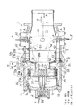
図2は燃焼器2の縦断面図を示し、この燃焼器2は、これに導入される圧縮空気Aと燃焼ガスGとが互いに燃焼器2内の逆方向に流れる逆流缶型であり、円筒状のハウジングH内に、ほぼ円筒状の燃焼筒12が収納され、燃焼筒12の内部に燃焼室13が形成されている。この燃焼器2は、図1の回転軸9の軸心と同心状の円筒上に複数(例えば6つ)配置されている。ハウジングHは、ハウジング本体H1の頭部にハウジングトップH2をボルト14で連結したものであり、ハウジングトップH2の先端側となる頭部にはエンドカバー18がボルト19により固定されている。
FIG. 2 shows a longitudinal sectional view of the
燃焼筒12は、外壁20と内壁21とにより、燃焼ガスGの流れ方向に沿った上流部が二重壁構造になっている。すなわち、燃焼筒12は、ノズルユニット(バーナユニット)28が外側ダクト28aを介して取り付けられた頭部12aと、その下流側に連設された円筒部12bとを有している。これに対応して、外壁20は、外側頭部20aと外側円筒部20bとを有し,外壁20と同心状に配置された内壁21は、内側頭部21aと、燃焼筒12の上流部のみに位置する短い内側円筒部21bとを有している。
The
外壁20の外側円筒部20bの上流部分には、径方向外方へ向け突出する環状の支持部材25が設けられており、この支持部材25の径方向外端部がハウジング本体H1の頭部にボルト22により連結されている。これにより、燃焼筒12の外壁20が支持部材25を介してハウジングHに支持されている。支持部材25には円周方向に並んだ複数の空気通過孔が設けられている。外壁20は、上流側端部でノズルユニット28の外側ダクト28aを支持し、この外側ダクト28aが内壁21を支持している。燃焼筒12の円筒部12bとこれを覆うハウジング本体H1との間には、圧縮機1からの圧縮空気Aを燃焼筒12の頭部12a、つまり、上流側へ導く環状の空気通路23が形成されている。ハウジングHにおけるエンドカバー18の内側には空気導入室24が形成されている。
An
燃焼筒12の頭部12aに取り付けられたノズルユニット28は、燃料Fを燃焼室13内に直接噴出する部分予混合方式のパイロットノズル29と、このパイロットノズル29の外周を囲むようにして、燃料Fと圧縮空気Aを混合して生成した予混合気Mを燃焼室13内に噴出する予混合型のメインノズル30とを備えている。
The
メインノズル30の縦断面L字状の予混合通路31の上流端は径方向外向きに開口しており、その開口した環状の空気取入口31aの径方向外側に複数のメイン燃料ノズル32がメインノズル30の周方向に等間隔で配置されている。メイン燃料ノズル32における空気取入口31aに対向する部分に、複数のメイン燃料噴射孔32aが形成されている。メイン燃料ノズル32の基端はエンドカバー18に設けたメイン燃料導入口33に接続されている。前記空気取入口31aには複数のスワーラ34が、燃焼筒12の軸心Cに沿った方向(軸心方向P)に並んで配置されている。メイン燃料噴射孔32aから供給された燃料Fは、空気通路23から空気導入室24内に導入された圧縮空気Aの一部とともに、スワーラ34によって旋回力が付与されながら予混合通路31に導入され、予混合通路31内で予混合されたのち、環状の予混合噴出口38から予混合気Mとして燃焼室13内に噴出される。
The upstream end of the L-shaped
パイロットノズル29に燃料Fを送給するパイロット燃料導入口39およびメイン燃料導入口33には、図1の燃料供給装置4から燃料制御装置8を介して燃料Fが供給される。
Fuel F is supplied from the fuel supply device 4 of FIG. 1 through the
図2の外側円筒部20bにおける内側円筒部21bの下流端近傍には、1つまたは複数の点火プラグ40が、その先端を燃焼室13内に臨ませて配置されている。点火プラグ40は、ハウジングHを貫通してハウジングHに固定されており、起動時には、パイロットノズル29から燃焼室13内に燃料Fを噴射して点火プラグ40による点火により拡散燃焼が行われる。続いて、通常運転時には、メインノズル30から燃焼室13内に噴射された予混合気Mを燃焼させて、燃焼筒12の上流部において、第1の燃焼領域S1を形成させる。また、燃焼筒12における第1の燃焼領域S1よりも下流側には、燃焼筒12の外壁20の外側円筒部20bを貫通した複数(例えば4つ)の貫通孔41が周方向に等間隔に設けられている。ハウジングHにおける各貫通孔41に対向する部分には、追焚きバーナ42が取り付けられて、その先端部を、貫通孔41を通して燃焼室13内に臨ませている。こうして、追焚きバーナ42から噴射される燃料Fにより、第1の燃焼領域S1の下流側に第2の燃焼領域S2が形成される。
In the vicinity of the downstream end of the inner
図3に示すように、燃焼筒12の頭部12aを含む上流部は、外壁20と内壁21とが所定の間隙を存し相対向して配置された二重壁構造になっている。この二重壁構造において、外壁20の頭部12aと円筒部12bの上流端部分とにインピンジ冷却領域43が設定され、このインピンジ冷却領域43の下流側に対流冷却領域44が設定されている。つまり、燃焼筒12の前記上流部は、インピンジ冷却領域43と対流冷却領域44とからなる。対流冷却領域44の下流側の外壁20にフィルム冷却領域48が設定されている。インピンジ冷却領域43における外壁20には、圧縮空気Aを冷却空気A1として内壁21に向けて二重壁内に導入する複数のインピンジ冷却孔49が等間隔で形成されている。
As shown in FIG. 3, the upstream portion including the
対流冷却領域44では、内壁21におけるインピンジ冷却領域43の下流側の外周面に、二重壁内を流れる冷却空気A1に乱れを与える乱流生成手段50Aが設けられている。乱流生成手段50Aは、内壁21の周方向に延びる環状リブを等間隔に、かつ互いに平行に複数形成した構成としている。なお、この実施形態では、外壁20における対流冷却領域44の全体にインピンジ冷却孔49を形成した場合を例示しているが、対流冷却領域44におけるインピンジ冷却を効果的に得られる上流部のみにインピンジ冷却孔49を設けるだけでもよい。
In the
フィルム冷却領域48は、内壁21の下流端に合致する対流冷却領域44の下流端に、二重壁内の空間を下流方向に開口させる排出口51を設けることで設定されている。排出口51からは、内壁21が無孔であることから、二重壁内の空間を下流側に向け流れてきた冷却空気A1のすべてが、フィルム冷却空気A2として燃焼室13内の外壁20の内周面に沿った方向に排出される。なお、図2では図示を省略したが、図3の外壁20の円筒部12bにおける対流冷却領域44よりも下流側の外周面の全体に、小さな多数の乱れ発生用リブ20eが一体形成されている。この乱れ発生用リブ20eは、空気通路23を通る圧縮空気Aによる外壁20の対流冷却部を促進する効果もある。
The
二重壁内の空間における外壁20の頭部12aと円筒部12aの上流端近傍および内壁21の下流端にそれぞれ対応する3箇所にスペーサー52,53,53が配設されている。これらスペーサー52,53,53は、外壁20と内壁21間の間隔を確保している。図3のIV−IV線断面図である図4に示すように、スペーサー53は、板材に周方向に並ぶ多数の凹凸53a,53bを直接形成した環状の部材である。外壁20と内壁21とスペーサー53との間に、冷却空気A1の排出口51が形成されている。外壁20の頭部12aに設けられるスペーサー52は、図3のV−V線断面図である図5に示すように、1つの凸部52aとこの周方向両側の2つの凹部52bとを有する短い部材であり、このスペーサー52が複数個(例えば6個)、周方向に並べて設けられる。
この実施形態のガスタービン燃焼器2は、図3に示す燃焼筒12の上流部に設けたインピンジ冷却領域43の外壁20に形成されたインピンジ冷却孔49から二重壁内に導入された冷却空気A1が内壁21に衝突して、内壁21をインピンジ冷却する。このインピンジ冷却後の冷却空気A1が下流側の対流冷却領域44の二重壁内を流動するときに、内壁21の外周面に設けた乱流生成手段50Aにより冷却空気A1に乱流が生じ、この冷却空気A1の乱流によって内壁21から冷却空気A1への伝熱が促進されて、冷却空気A1による対流冷却効果が向上する。
The
対流冷却領域44では、外壁20に設けたインピンジ冷却孔49から導入される冷却空気A1が内壁21に衝突することで、対流冷却に加えてインピンジ冷却も行われるので、冷却効果がさらに向上する。特に、対流冷却領域44の上流部では、インピンジ冷却領域43から流動してきた冷却空気A1の流量がさほど多くないのに伴って流速も比較的遅いので、対流冷却領域44における外壁20の上流部のインピンジ冷却孔49から二重壁内に導入される圧縮空気Aは、二重壁内の空間を流れる冷却空気A1によるクロスフローの干渉をさほど受けることなく、内壁21に衝突する。したがって、対流冷却領域44の少なくとも上流部では、インピンジ冷却が効果的になされる。
In the
さらに、対流冷却領域44の全体、特に下流部では、外壁20のインピンジ冷却孔49から二重壁内に導入される圧縮空気Aが、乱流生成手段50Aによって乱流が発生した冷却空気A1を攪拌するので、対流冷却による冷却効果が一層向上する。
Further, in the entire
したがって、この実施形態のガスタービン燃焼器2では、図2の燃焼室13における特に高温の第1の燃焼領域S1が形成される上流部に対応する内壁21を、冷却効果の優れたインピンジ冷却に加えて、対流冷却によっても効果的、かつ効率的に冷却することができるので、燃焼筒12の所期の寿命を確保できる。
Therefore, in the
さらに、二重壁内の冷却空気A1は、図3のインピンジ冷却領域43から対流冷却領域44に向け流動するにしたがって流量および流速が共に増大した状態で、対流冷却領域44の下流端に設けた、二重壁内の空間を下流方向に開口させる排出口51から、燃焼室13内にフィルム冷却空気A2として排出される。この大量のフィルム冷却空気A2は、速い流速で外壁20の内面に沿って層状に流れることにより、図2の第1および第2の燃焼領域S1,S2の高温の燃焼ガスGが内壁21に接触するのを防止するように作用して、外壁20を効果的にフィルム冷却する。特に、このガスタービン燃焼器2では、内壁21が無孔であり、かつ、図3の対流冷却領域44にある外壁20の全体にインピンジ冷却孔49を設けているから、二重壁内の空間に多量の冷却空気A1が導入されるので、この多量の冷却空気A1のすべてがフィルム冷却空気A2として有効に利用されることにより、燃焼筒12の外壁20を高い冷却効率でフィルム冷却することができる。
Further, the cooling air A1 in the double wall is provided at the downstream end of the
しかも、燃焼筒12は、外壁20にインピンジ冷却孔49を設け、無孔の内壁21の外周面に、エッチングまたは機械加工により容易に形成できる環状リブからなる乱流生成手段50Aを設けるだけであるので、一般的な燃焼筒に小さなフィルム冷却孔を多数形成する構造や、燃焼筒の軸心方向に沿って分割した複数の内壁および外壁を重ね合わせて連結する構造に比べて簡単な構造となり、安価に製造することができる。
Moreover, the
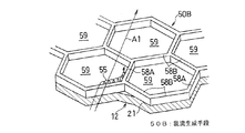
前記実施形態では、二重壁内の冷却空気A1に乱れを与えるための乱流生成手段50Aとして環状リブを設ける場合を例示したが、乱流生成手段50Aは環状リブに限られない。例えば、図6に示すような乱流生成手段50Bを設けてよい。この乱流生成手段50Bは、燃焼筒12の内壁21の外周面から突出した6つのリブ58A,58Bからなる正六角形のセル59が連続して多数配置されたハニカム構造になっている。この乱流生成手段50Bでは、冷却空気A1が、これの流れ方向に対し斜めのリブ58Bを乗り越える際に旋回流55が発生し、この旋回流55により冷却空気A1が攪拌されて、内壁21から冷却空気A1への熱伝達が効率的に行われることにより、内壁21の対流冷却効果が一層向上する。
In the above embodiment, the case where the annular rib is provided as the turbulent flow generation means 50A for giving turbulence to the cooling air A1 in the double wall is illustrated, but the turbulent flow generation means 50A is not limited to the annular rib. For example, you may provide the turbulent flow production | generation means 50B as shown in FIG. The turbulent flow generation means 50B has a honeycomb structure in which a number of regular
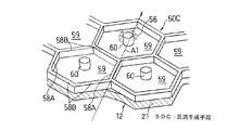
また、図7に示すような乱流発生手段50Cを設けてもよい。この乱流発生手段50Cは、燃焼筒12(図2)の内壁21の外周面に、図6の乱流発生手段50Bと同様の正六角形のセル59が連続して多数配置されたハニカム構造が設けられているとともに、各セル59の中央部に、リブ58A,58Bの高さと同一の高さを有する円柱形の独立リブ60を立設したものである。この乱流発生手段50Cは、図5で説明したと同様の効果が得られるのに加えて、セル59の中央部において、独立リブ60の後方で圧縮空気Aの渦流56が発生し、この渦流56により冷却空気A1の攪拌が行われるので、内壁21が場所的に均等に冷却される利点がある。
Moreover, you may provide the turbulent flow generation means 50C as shown in FIG. The turbulent flow generating means 50C has a honeycomb structure in which a large number of regular
さらに、図8に示すような乱流発生手段50Dを設けてよい。この乱流発生手段50Dは、四つのリブ61で囲まれた平面視で菱形のセル62を連続させたハニカム構造になっており、菱形の4つの辺を形成するリブ61はいずれも冷却空気A1の流れ方向に対して斜めに交差した配置になっているので、すべてのリブ61によって冷却空気A1に旋回流が発生して、冷却空気A1が十分に攪拌されるので、内壁21が効率的に冷却される。
Furthermore, a turbulent flow generation means 50D as shown in FIG. 8 may be provided. This turbulent flow generation means 50D has a honeycomb structure in which
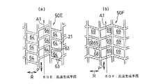
さらにまた、図9(a)(b)に示すような乱流発生手段50E,50Fを設けてもよい。図9(a)の乱流発生手段50Eは、四つのリブ63で囲まれた平面視で平行四辺形のセル64を連続させたハニカム構造になっており、各セル64は、燃焼筒12(図2)の周方向Rに隣接するもの同士が、冷却空気A1の流れ方向に対して逆方向に傾斜しており、かつ燃焼筒12(図2)の軸心方向Pに沿って所定ピッチずれて配列されている。図9(b)に示す乱流発生手段50Fも同様に、四つのリブ68で囲まれた平行四辺形のセル69を連続させたハニカム構造になっているが、図9(a)の乱流発生手段50Eとは異なり、各セル69は、燃焼筒12(図2)の周方向Rに隣接するもの同士が、燃焼筒12(図2)の軸心方向Pに沿って同一位置に配置されており、この軸心方向Pに沿った配列ピッチがずれていない。これら乱流発生手段50E,50Fにおいても、各セル64,69における冷却空気A1の流れ方向に対し斜めに交差した各二つのリブ63,68によって冷却空気A1に旋回流が発生し、冷却空気A1が十分に攪拌される。
Furthermore, you may provide the turbulent flow generation means 50E and 50F as shown to Fig.9 (a) (b). The turbulent flow generating means 50E of FIG. 9A has a honeycomb structure in which
さらに、図10に示すような乱流発生手段50Gを設けてよい。この乱流発生手段50Gは、三つのリブ70A,70Bで囲まれた正三角形のセル71を連続させたハニカム構造になっており、各三角形の1辺が冷却空気A1の流れ方向に沿って延びた平行リブ70Aにより形成され、他の2辺が斜めリブ70Bにより形成されている。なお、正三角形以外の三角形状でもよい。三角形はいずれの向きに配置しても、少なくとも1つの辺は、冷却空気A1の流れ方向に対して90°未満の角度で交差する。これにより、少なくとも1つの辺が冷却空気A1に旋回流を発生させることで、対流冷却効果が向上する。
Furthermore, a turbulent flow generation means 50G as shown in FIG. 10 may be provided. The turbulent flow generation means 50G has a honeycomb structure in which regular triangular cells 71 surrounded by three
本発明は、以上の各実施形態で示した内容に限定されるものでなく、本発明の要旨を逸脱しない範囲内で、種々の追加、変更または削除が可能であり、そのようなものも本発明の範囲内に含まれる。 The present invention is not limited to the contents shown in the above embodiments, and various additions, modifications or deletions can be made without departing from the gist of the present invention. Included within the scope of the invention.
1 圧縮機
12 燃焼筒
12a 頭部
12b 円筒部
13 燃焼室
20 外壁
21 内壁
28 ノズルユニット
43 インピンジ冷却領域
44 対流冷却領域
49 インピンジ冷却孔
50A 乱流生成手段(環状リブ)
50B〜50G 乱流生成手段
51 排出口
A 圧縮空気
A2 フィルム冷却空気
DESCRIPTION OF
50B-50G Turbulent flow generation means 51 Discharge port A Compressed air A2 Film cooling air
Claims (5)
前記二重壁構造の上流部にインピンジ冷却領域とその下流側の対流冷却領域とが設定され、
前記インピンジ冷却領域と対流冷却領域のうちの少なくともインピンジ冷却領域の外壁に、圧縮機からの圧縮空気を前記内壁に向けて導入するインピンジ冷却孔が形成され、
前記対流冷却領域の内壁の外周面に二重壁内の圧縮空気に乱れを与える乱流生成手段が設けられ、
前記対流冷却領域の下流端に、前記二重壁内の空間を下流方向に開口させて、前記二重壁内の圧縮空気をフィルム冷却空気として排出する排出口が設けられているガスタービン燃焼器。 A part of the combustion cylinder forming the combustion chamber has a double wall structure consisting of an outer wall and an inner wall,
An impingement cooling region and a convection cooling region downstream thereof are set in the upstream portion of the double wall structure,
Impinge cooling holes for introducing compressed air from the compressor toward the inner wall are formed on the outer wall of at least the impingement cooling region of the impingement cooling region and the convection cooling region,
Turbulent flow generating means is provided on the outer peripheral surface of the inner wall of the convection cooling region to disturb the compressed air in the double wall,
A gas turbine combustor having a discharge port for opening the space in the double wall in the downstream direction at the downstream end of the convection cooling region and discharging the compressed air in the double wall as film cooling air .
Priority Applications (1)
| Application Number | Priority Date | Filing Date | Title |
|---|---|---|---|
| JP2009144986A JP5320177B2 (en) | 2009-06-18 | 2009-06-18 | Gas turbine combustor |
Applications Claiming Priority (1)
| Application Number | Priority Date | Filing Date | Title |
|---|---|---|---|
| JP2009144986A JP5320177B2 (en) | 2009-06-18 | 2009-06-18 | Gas turbine combustor |
Publications (3)
| Publication Number | Publication Date |
|---|---|
| JP2011001868A JP2011001868A (en) | 2011-01-06 |
| JP2011001868A5 JP2011001868A5 (en) | 2012-07-19 |
| JP5320177B2 true JP5320177B2 (en) | 2013-10-23 |
Family
ID=43560029
Family Applications (1)
| Application Number | Title | Priority Date | Filing Date |
|---|---|---|---|
| JP2009144986A Expired - Fee Related JP5320177B2 (en) | 2009-06-18 | 2009-06-18 | Gas turbine combustor |
Country Status (1)
| Country | Link |
|---|---|
| JP (1) | JP5320177B2 (en) |
Families Citing this family (3)
| Publication number | Priority date | Publication date | Assignee | Title |
|---|---|---|---|---|
| JP7411458B2 (en) * | 2020-03-11 | 2024-01-11 | 三菱重工業株式会社 | Combustion tube installation method and combustion tube installation jig |
| CN111288490A (en) * | 2020-03-23 | 2020-06-16 | 上海电力大学 | Combustion chamber device of high-temperature backflow zone at scattered boss |
| CN113483354B (en) * | 2021-07-16 | 2023-07-07 | 西北工业大学 | Bent truss structure heat shield for afterburner and method for forming air film |
Family Cites Families (5)
| Publication number | Priority date | Publication date | Assignee | Title |
|---|---|---|---|---|
| US4567730A (en) * | 1983-10-03 | 1986-02-04 | General Electric Company | Shielded combustor |
| JPH0660740B2 (en) * | 1985-04-05 | 1994-08-10 | 工業技術院長 | Gas turbine combustor |
| US5012645A (en) * | 1987-08-03 | 1991-05-07 | United Technologies Corporation | Combustor liner construction for gas turbine engine |
| US4916906A (en) * | 1988-03-25 | 1990-04-17 | General Electric Company | Breach-cooled structure |
| JP3590666B2 (en) * | 1995-03-30 | 2004-11-17 | 株式会社東芝 | Gas turbine combustor |
-
2009
- 2009-06-18 JP JP2009144986A patent/JP5320177B2/en not_active Expired - Fee Related
Also Published As
| Publication number | Publication date |
|---|---|
| JP2011001868A (en) | 2011-01-06 |
Similar Documents
| Publication | Publication Date | Title |
|---|---|---|
| EP2233837B1 (en) | Burner, combustor and remodeling method for burner | |
| JP5557521B2 (en) | Premixed direct injection disc | |
| JP4797079B2 (en) | Gas turbine combustor | |
| JP5860620B2 (en) | Injection nozzle for turbomachine | |
| CA2546881C (en) | Gas turbine engine combustor with improved cooling | |
| JP5933491B2 (en) | Gas turbine combustion system | |
| EP2500655B1 (en) | Gas turbine combustor and gas turbine | |
| JP2010091258A (en) | Premixed direct injection nozzle | |
| JP2012017971A5 (en) | ||
| JP2010223577A6 (en) | Swirl, method for preventing backfire in burner equipped with at least one swirler, and burner | |
| JP6050675B2 (en) | System and method for reducing combustion dynamics in a combustor | |
| US11421882B2 (en) | Swirler, combustor assembly, and gas turbine with improved fuel/air mixing | |
| JPH08246900A (en) | Combustion apparatus for gas or liquid fuel turbine and operating method of turbine | |
| JP2015105766A (en) | Nozzle, combustor, and gas turbine | |
| JP4756078B2 (en) | Gas turbine combustor | |
| JP5320177B2 (en) | Gas turbine combustor | |
| JP5537895B2 (en) | Gas turbine combustor | |
| JP2014105886A (en) | Combustor | |
| JP2004162959A (en) | Annular type spiral diffusion flame combustor | |
| JP6037736B2 (en) | Gas turbine combustor and gas turbine engine equipped with the same | |
| JP7132096B2 (en) | gas turbine combustor | |
| JP2010038538A (en) | Swirler and swirler assembly | |
| JP2010038538A6 (en) | Swivel blade and swirl device | |
| JP6158504B2 (en) | Burner | |
| JP2015218946A (en) | Gas turbine combustor |
Legal Events
| Date | Code | Title | Description |
|---|---|---|---|
| A521 | Written amendment |
Free format text: JAPANESE INTERMEDIATE CODE: A523 Effective date: 20120606 |
|
| A621 | Written request for application examination |
Free format text: JAPANESE INTERMEDIATE CODE: A621 Effective date: 20120606 |
|
| A977 | Report on retrieval |
Free format text: JAPANESE INTERMEDIATE CODE: A971007 Effective date: 20130415 |
|
| A131 | Notification of reasons for refusal |
Free format text: JAPANESE INTERMEDIATE CODE: A131 Effective date: 20130423 |
|
| A521 | Written amendment |
Free format text: JAPANESE INTERMEDIATE CODE: A523 Effective date: 20130617 |
|
| TRDD | Decision of grant or rejection written | ||
| A01 | Written decision to grant a patent or to grant a registration (utility model) |
Free format text: JAPANESE INTERMEDIATE CODE: A01 Effective date: 20130709 |
|
| A61 | First payment of annual fees (during grant procedure) |
Free format text: JAPANESE INTERMEDIATE CODE: A61 Effective date: 20130712 |
|
| R150 | Certificate of patent or registration of utility model |
Free format text: JAPANESE INTERMEDIATE CODE: R150 |
|
| LAPS | Cancellation because of no payment of annual fees |