JP5319761B2 - Cassette for differential-pressure-based drug administration flow sensor assembly for monitoring drug administration and method for making the same - Google Patents
Cassette for differential-pressure-based drug administration flow sensor assembly for monitoring drug administration and method for making the same Download PDFInfo
- Publication number
- JP5319761B2 JP5319761B2 JP2011510701A JP2011510701A JP5319761B2 JP 5319761 B2 JP5319761 B2 JP 5319761B2 JP 2011510701 A JP2011510701 A JP 2011510701A JP 2011510701 A JP2011510701 A JP 2011510701A JP 5319761 B2 JP5319761 B2 JP 5319761B2
- Authority
- JP
- Japan
- Prior art keywords
- fluid
- flow
- restricting element
- fluid pressure
- membrane
- Prior art date
- Legal status (The legal status is an assumption and is not a legal conclusion. Google has not performed a legal analysis and makes no representation as to the accuracy of the status listed.)
- Active
Links
Images


Classifications
-
- A—HUMAN NECESSITIES
- A61—MEDICAL OR VETERINARY SCIENCE; HYGIENE
- A61M—DEVICES FOR INTRODUCING MEDIA INTO, OR ONTO, THE BODY; DEVICES FOR TRANSDUCING BODY MEDIA OR FOR TAKING MEDIA FROM THE BODY; DEVICES FOR PRODUCING OR ENDING SLEEP OR STUPOR
- A61M5/00—Devices for bringing media into the body in a subcutaneous, intra-vascular or intramuscular way; Accessories therefor, e.g. filling or cleaning devices, arm-rests
- A61M5/14—Infusion devices, e.g. infusing by gravity; Blood infusion; Accessories therefor
- A61M5/168—Means for controlling media flow to the body or for metering media to the body, e.g. drip meters, counters ; Monitoring media flow to the body
- A61M5/16886—Means for controlling media flow to the body or for metering media to the body, e.g. drip meters, counters ; Monitoring media flow to the body for measuring fluid flow rate, i.e. flowmeters
-
- A—HUMAN NECESSITIES
- A61—MEDICAL OR VETERINARY SCIENCE; HYGIENE
- A61M—DEVICES FOR INTRODUCING MEDIA INTO, OR ONTO, THE BODY; DEVICES FOR TRANSDUCING BODY MEDIA OR FOR TAKING MEDIA FROM THE BODY; DEVICES FOR PRODUCING OR ENDING SLEEP OR STUPOR
- A61M5/00—Devices for bringing media into the body in a subcutaneous, intra-vascular or intramuscular way; Accessories therefor, e.g. filling or cleaning devices, arm-rests
- A61M5/14—Infusion devices, e.g. infusing by gravity; Blood infusion; Accessories therefor
- A61M5/168—Means for controlling media flow to the body or for metering media to the body, e.g. drip meters, counters ; Monitoring media flow to the body
- A61M5/16831—Monitoring, detecting, signalling or eliminating infusion flow anomalies
- A61M5/16854—Monitoring, detecting, signalling or eliminating infusion flow anomalies by monitoring line pressure
-
- A—HUMAN NECESSITIES
- A61—MEDICAL OR VETERINARY SCIENCE; HYGIENE
- A61M—DEVICES FOR INTRODUCING MEDIA INTO, OR ONTO, THE BODY; DEVICES FOR TRANSDUCING BODY MEDIA OR FOR TAKING MEDIA FROM THE BODY; DEVICES FOR PRODUCING OR ENDING SLEEP OR STUPOR
- A61M2205/00—General characteristics of the apparatus
- A61M2205/33—Controlling, regulating or measuring
- A61M2205/3331—Pressure; Flow
- A61M2205/3334—Measuring or controlling the flow rate
-
- Y—GENERAL TAGGING OF NEW TECHNOLOGICAL DEVELOPMENTS; GENERAL TAGGING OF CROSS-SECTIONAL TECHNOLOGIES SPANNING OVER SEVERAL SECTIONS OF THE IPC; TECHNICAL SUBJECTS COVERED BY FORMER USPC CROSS-REFERENCE ART COLLECTIONS [XRACs] AND DIGESTS
- Y10—TECHNICAL SUBJECTS COVERED BY FORMER USPC
- Y10T—TECHNICAL SUBJECTS COVERED BY FORMER US CLASSIFICATION
- Y10T29/00—Metal working
- Y10T29/49—Method of mechanical manufacture
- Y10T29/49826—Assembling or joining
Landscapes
- Health & Medical Sciences (AREA)
- Vascular Medicine (AREA)
- Engineering & Computer Science (AREA)
- Anesthesiology (AREA)
- Biomedical Technology (AREA)
- Heart & Thoracic Surgery (AREA)
- Hematology (AREA)
- Life Sciences & Earth Sciences (AREA)
- Animal Behavior & Ethology (AREA)
- General Health & Medical Sciences (AREA)
- Public Health (AREA)
- Veterinary Medicine (AREA)
- Physics & Mathematics (AREA)
- Fluid Mechanics (AREA)
- Infusion, Injection, And Reservoir Apparatuses (AREA)
Abstract
Description
本発明は、差圧利用フローセンサ組立体ならびに差圧利用フローセンサ組立体を収容したシステムを用いる薬剤投与を監視する方法に概ね関するものであり、より具体的には使い捨て可能部分と再利用可能部分とを有する差圧利用フローセンサ組立体に関するものである。より具体的には、本発明はこの種のフローセンサ組立体の使い捨て可能部分として機能するカセットとその製造方法に関する。 The present invention relates generally to a differential pressure-based flow sensor assembly and a method for monitoring drug administration using a system containing a differential pressure-based flow sensor assembly, and more particularly to a disposable part and reusable. And a differential pressure-based flow sensor assembly. More specifically, the present invention relates to a cassette that functions as a disposable part of this type of flow sensor assembly and a method for manufacturing the same.
医用ポンプを含む最新の医療デバイスは、患者に流体、溶液、薬剤、薬物を投与するのにますますマイクロプロセッサ利用システムにより制御されつつある。医用ポンプ用の一般的な制御には、開業医が投与対象である流体の薬量、流体投与流量、継続時間、患者に点滴する流体の体積を入力できるようにするユーザインタフェースが含まれる。一般に、薬剤投与は連続的な点滴として、あるいは単一の注入器による一回注入量として行なわれるようプログラムされる。 Modern medical devices, including medical pumps, are increasingly being controlled by microprocessor-based systems to administer fluids, solutions, drugs, and drugs to patients. General controls for a medical pump include a user interface that allows the practitioner to enter the fluid dose to be administered, the fluid delivery flow rate, the duration, and the volume of fluid to be infused into the patient. In general, drug administration is programmed to occur as a continuous infusion or as a single infusion with a single syringe.
各チャネルから異なる流体を施薬する多チャネル点滴ポンプの使用もしくは複数の単一チャネル点滴ポンプの使用により複数の薬剤を患者に点滴することは、当たり前のことである。複数の薬剤を患者へ投与する別の方法は、点滴ポンプを使用する第1の薬剤と単一の注入器による一回注入量を介する追加の薬剤の投与である。 It is natural to instill multiple drugs into a patient by using a multi-channel infusion pump that dispenses different fluids from each channel or by using multiple single-channel infusion pumps. Another method of administering multiple drugs to a patient is the administration of additional drugs via a single infusion volume with a first drug and a single syringe using an infusion pump.
単一の注入器による一回注入量(bolus dose)を介して薬剤を投与するときは、患者に正規の薬剤が投与されていることの検証に加え患者に正規の量の薬剤が投与されていることの検証もまた重要である。一般に、介護者は患者の書面カルテ上に注入器による一回注入量を介して投与される薬剤の量を単純に手書きで注記し、その情報を後刻患者の記録内に電子的に入力することができる。こうして、人為的過失が偶発的な薬剤の過剰投与または過小投与に通ずることがあるものの、介護者は適切な薬量が投与されたものと信ずることになる。薬剤投薬の過失に加え、人為的過失が単一の注入器による一回注入量中に投与される薬剤を記録する上での障害を生ずることもある。こうして、患者に投与されてきた各薬剤が患者の医療記録に反映されないような可能性がある。広範な流体と流量を計測することのできる点滴ライン(IV line)内のセンサは、そのラインを介してその患者に与えられる各薬剤の流量と体積の文書記録に役立つことになる。さらに、低コストで、特に使い捨て可能な薬剤投与配管セットに対し低い割増コストをもたらすしっかりとした流量検出方法論を提供することが望ましい。さらに、厳密には知ることの出来ない流体粘性を含む所定範囲の物理的特性を有する流体の流量を正確に検出することのできる流量検出方法論を提供することが望ましい。その結果、薬剤投与を監視するよう適合させた差圧利用フローセンサシステムに対する必要性が存在する。 When administering a drug via a single dose with a single syringe, the patient is administered the correct amount of drug in addition to verifying that the patient is receiving the correct drug. Verification is also important. In general, the caregiver simply notes by hand on the patient's written chart the amount of drug that will be administered via a single infusion by syringe, and later enters that information electronically in the patient's record. Can do. Thus, although human error may lead to accidental drug overdose or underdose, the caregiver believes that the appropriate dose has been administered. In addition to drug medication errors, human error can cause difficulties in recording the drugs administered during a single infusion with a single syringe. In this way, each drug that has been administered to the patient may not be reflected in the patient's medical record. A sensor in an infusion line (IV line) capable of measuring a wide range of fluids and flow rates will help document the flow and volume of each drug delivered to the patient via that line. In addition, it is desirable to provide a robust flow detection methodology that provides low cost, especially low cost for a disposable drug delivery tubing set. Furthermore, it is desirable to provide a flow rate detection methodology that can accurately detect the flow rate of a fluid having a predetermined range of physical characteristics including fluid viscosity that cannot be precisely known. As a result, there is a need for a differential pressure based flow sensor system adapted to monitor drug administration.
一実施形態によれば、流体システムの流量(rate)を特定するよう適合させた差圧利用フローセンサ組立体は使い捨て可能部分と再利用可能部分とを備える。使い捨て可能部分は、流入口と流出口とを形成する流体流路を画定する本体を有する。フロー制限要素は、流入口と流出口との間の流体流路沿いに位置決めする。使い捨て可能部分はさらに、流入口とフロー制限要素との間の流体流路内の所定位置に上流流体圧力膜を有する。下流流体圧力膜は、フロー制限要素と使い捨て可能部分の流出口との間の流体流路内に配置する。 According to one embodiment, a differential pressure based flow sensor assembly adapted to identify a flow rate of a fluid system comprises a disposable part and a reusable part. The disposable portion has a body that defines a fluid flow path that forms an inlet and an outlet. The flow restricting element is positioned along the fluid flow path between the inlet and the outlet. The disposable portion further has an upstream fluid pressure membrane in place in the fluid flow path between the inlet and the flow restricting element. A downstream fluid pressure membrane is disposed in the fluid flow path between the flow restriction element and the outlet of the disposable part.
再利用可能部分は、上流流体圧力センサと下流流体圧力センサとを有する。上流流体圧力センサは、流入口とフロー制限要素との間の流体流路内の所定箇所で上流流体圧力を検出する。上流流体圧力センサは、上流流体圧力膜の流体圧力を測定するよう位置決めされる。 The reusable part has an upstream fluid pressure sensor and a downstream fluid pressure sensor. The upstream fluid pressure sensor detects upstream fluid pressure at a predetermined location in the fluid flow path between the inlet and the flow restricting element. The upstream fluid pressure sensor is positioned to measure the fluid pressure of the upstream fluid pressure membrane.
下流流体圧力センサは、フロー制限要素と流出口との間の流体流路内の所定箇所で下流流体圧力を検出する。下流流体圧力センサは、下流流体圧力膜にて流体圧力を測定するよう位置決めされる。 The downstream fluid pressure sensor detects the downstream fluid pressure at a predetermined location in the fluid flow path between the flow restriction element and the outlet. The downstream fluid pressure sensor is positioned to measure fluid pressure at the downstream fluid pressure membrane.
別の実施形態によれば、差圧利用流体フロー組立体と共に用いる使い捨て可能組立体は、本体とフロー制限要素と上流流体圧力膜と下流流体圧力膜とを備える。本体は、流入口と流出口を形成する流体流路を画定する。フロー制限要素は、流体流路内で流入口と流出口との間に位置決めされる。上流流体圧力膜は、流入口と流体制限要素との間の流体流路内に配置される。下流流体圧力膜は、流体制限要素と流出口との間の流体流路内に配置される。 According to another embodiment, a disposable assembly for use with a differential pressure based fluid flow assembly includes a body, a flow restricting element, an upstream fluid pressure membrane, and a downstream fluid pressure membrane. The body defines a fluid flow path that forms an inlet and an outlet. The flow restricting element is positioned between the inlet and the outlet in the fluid flow path. An upstream fluid pressure membrane is disposed in the fluid flow path between the inlet and the fluid restriction element. A downstream fluid pressure membrane is disposed in the fluid flow path between the fluid restriction element and the outlet.
一つの方法によれば、流体フローシステム内の流体流量が測定される。本方法は、差圧利用フローセンサ組立体を用いる。センサ組立体は、使い捨て可能部分と再利用可能部分とで構成される。使い捨て可能部分は、流入口と流出口を形成する流体流路を画定する本体を有する。フロー制限要素は、流入口と流出口との間の流体流路に沿って位置決めする。使い捨て可能部分はさらに、流入口とフロー制限要素との間の流体流路内の所定箇所に上流流体圧力膜を有する。下流流体圧力膜は、フロー制限要素と使い捨て可能部分の流出口との間の流体流路内に配置される。再利用可能部分は、上流流体圧力センサと下流流体圧力センサとを有する。 According to one method, the fluid flow rate in the fluid flow system is measured. The method uses a differential pressure based flow sensor assembly. The sensor assembly is composed of a disposable part and a reusable part. The disposable portion has a body that defines a fluid flow path that forms an inlet and an outlet. The flow restricting element is positioned along the fluid flow path between the inlet and the outlet. The disposable portion further has an upstream fluid pressure membrane at a predetermined location in the fluid flow path between the inlet and the flow restricting element. A downstream fluid pressure membrane is disposed in the fluid flow path between the flow restriction element and the outlet of the disposable part. The reusable part has an upstream fluid pressure sensor and a downstream fluid pressure sensor.
上流流体圧力センサは、流入口とフロー制限要素との間の流体流路内の所定箇所で上流流体圧力を検出する。上流流体圧力センサは、上流流体圧力膜の流体圧力を測定するよう位置決めする。下流流体圧力センサは、フロー制限要素と流出口との間の流体流路内の所定箇所で下流流体圧力を検出する。 The upstream fluid pressure sensor detects upstream fluid pressure at a predetermined location in the fluid flow path between the inlet and the flow restricting element. The upstream fluid pressure sensor is positioned to measure the fluid pressure of the upstream fluid pressure membrane. The downstream fluid pressure sensor detects the downstream fluid pressure at a predetermined location in the fluid flow path between the flow restriction element and the outlet.
下流流体圧力センサは、下流流体圧力膜の流体圧力を測定するよう位置決めする。流体は、流体流路を通って案内される。本方法は、上流流体圧力センサの出力と下流流体圧力センサの出力との間の差圧に基づき流体の流量を算出する。 The downstream fluid pressure sensor is positioned to measure the fluid pressure of the downstream fluid pressure membrane. The fluid is guided through the fluid flow path. The method calculates a fluid flow rate based on the differential pressure between the output of the upstream fluid pressure sensor and the output of the downstream fluid pressure sensor.
さらなる実施形態によれば、第1の薬剤源から患者へ流体薬剤を投与して流体の流量を測定する流体投与システムは、点滴ポンプと差圧利用フローセンサ組立体とプロセッサとを備える。点滴ポンプは、流体ラインを介する第1の薬剤源からの第1の薬剤の流量を選択的に変更する。差圧利用フローセンサ組立体は、流体ライン内の第1の薬剤の流量を測定する。 According to a further embodiment, a fluid delivery system for administering fluid medication from a first medication source to a patient and measuring fluid flow includes an infusion pump, a differential pressure based flow sensor assembly, and a processor. The infusion pump selectively changes the flow rate of the first drug from the first drug source via the fluid line. The differential pressure based flow sensor assembly measures the flow rate of the first drug in the fluid line.
センサ組立体は、使い捨て可能部分と再利用可能部分とを有する。使い捨て可能部分は、流入口と流出口を形成する流体流路を画定する本体を有する。フロー制限要素は、流入口と流出口との間の流体流路に沿って位置決めされる。使い捨て可能部分はさらに、流入口とフロー制限要素との間の流体流路内の所定箇所に上流流体圧力膜を有する。下流流体圧力膜は、フロー制限要素と使い捨て可能部分の流出口との間の流体流路内に配置する。 The sensor assembly has a disposable part and a reusable part. The disposable portion has a body that defines a fluid flow path that forms an inlet and an outlet. The flow restricting element is positioned along the fluid flow path between the inlet and the outlet. The disposable portion further has an upstream fluid pressure membrane at a predetermined location in the fluid flow path between the inlet and the flow restricting element. A downstream fluid pressure membrane is disposed in the fluid flow path between the flow restriction element and the outlet of the disposable part.
再利用可能部分は、上流流体圧力センサと下流流体圧力センサとを有する。上流流体圧力センサは、流入口とフロー制限要素との間の流体流路内の所定箇所で上流流体圧力を検出する。上流流体圧力センサは、上流流体圧力膜の流体圧力を測定するよう位置決めする。 The reusable part has an upstream fluid pressure sensor and a downstream fluid pressure sensor. The upstream fluid pressure sensor detects upstream fluid pressure at a predetermined location in the fluid flow path between the inlet and the flow restricting element. The upstream fluid pressure sensor is positioned to measure the fluid pressure of the upstream fluid pressure membrane.
下流流体圧力センサは、フロー制限要素と流出口との間の流体流路内の所定箇所で下流流体圧力を検出する。下流流体圧力センサは、下流流体圧力膜の流体圧力を測定するよう位置決めする。 The downstream fluid pressure sensor detects the downstream fluid pressure at a predetermined location in the fluid flow path between the flow restriction element and the outlet. The downstream fluid pressure sensor is positioned to measure the fluid pressure of the downstream fluid pressure membrane.
プロセッサは、差圧利用フローセンサ組立体が供給する情報に基づき第1の薬剤の流量を変更することで点滴ポンプを制御するよう適合させる。プロセッサはまた、患者に供給される第1の薬剤の量を測定するよう適合させる。 The processor is adapted to control the infusion pump by changing the flow rate of the first medication based on information provided by the differential pressure based flow sensor assembly. The processor is also adapted to measure the amount of the first medication delivered to the patient.
さらに別の方法は、差圧利用フローセンサ組立体を用いて患者へ薬剤を投与し、流体ライン内の第1の薬剤の流量を測定する。センサ組立体は、使い捨て可能部分と再利用可能部分とを備える。使い捨て可能部分は、流入口と流出口を形成する流体流路を画定する本体を有する。フロー制限要素は、流入口と流出口との間の流体流路に沿って位置決めする。使い捨て可能部分はさらに、流入口とフロー制限要素との間の流体流路内の所定箇所に上流流体圧力膜を有する。下流流体圧力膜は、フロー制限要素と使い捨て可能部分の流出口との間の流体流路内に配置する。 Yet another method uses a differential pressure based flow sensor assembly to administer medication to a patient and measure the flow rate of the first medication in the fluid line. The sensor assembly includes a disposable part and a reusable part. The disposable portion has a body that defines a fluid flow path that forms an inlet and an outlet. The flow restricting element is positioned along the fluid flow path between the inlet and the outlet. The disposable portion further has an upstream fluid pressure membrane at a predetermined location in the fluid flow path between the inlet and the flow restricting element. A downstream fluid pressure membrane is disposed in the fluid flow path between the flow restriction element and the outlet of the disposable part.
再利用可能部分は、上流流体圧力センサと下流流体圧力センサとを有する。上流流体圧力センサは、流入口とフロー制限要素との間の流体流路内の所定箇所で上流流体圧力を検出する。上流流体圧力センサは、上流流体圧力膜の流体圧力を測定するよう位置決めする。下流流体圧力センサは、フロー制限要素と流出口との間の流体流路内の所定箇所で下流流体圧力を検出する。下流流体圧力センサは、下流流体圧力膜の流体圧力を測定するよう位置決めする。 The reusable part has an upstream fluid pressure sensor and a downstream fluid pressure sensor. The upstream fluid pressure sensor detects upstream fluid pressure at a predetermined location in the fluid flow path between the inlet and the flow restricting element. The upstream fluid pressure sensor is positioned to measure the fluid pressure of the upstream fluid pressure membrane. The downstream fluid pressure sensor detects the downstream fluid pressure at a predetermined location in the fluid flow path between the flow restriction element and the outlet. The downstream fluid pressure sensor is positioned to measure the fluid pressure of the downstream fluid pressure membrane.
本方法は、フローセンサ組立体を用いて第1の薬剤の流量を検出する。第1の薬剤の流量を選択的に変更する点滴ポンプは、流体センサ組立体がプロセッサへ供給する情報に基づき制御する。本方法は、患者へ給送される第1の薬剤の量を流体センサ組立体がプロセッサへ供給する情報に基づき決定する。 The method uses a flow sensor assembly to detect the flow rate of the first drug. An infusion pump that selectively changes the flow rate of the first medication is controlled based on information supplied by the fluid sensor assembly to the processor. The method determines the amount of first medication delivered to the patient based on information that the fluid sensor assembly provides to the processor.
さらなる方法は、流体フローシステム内の流体の流量を測定する。上流圧力センサを、流体流路に配設する。下流圧力センサもまた、流体流路に配設する。本方法は、上流圧力センサと下流圧力センサとの間の流体流路沿いにフロー制限要素を用いる。流体は、流体流路を介して導かれる。流体の流量は、上流流体圧力センサの出力と下流流体圧力センサの出力との間の差圧に基づき算出される。 A further method measures the flow rate of fluid in the fluid flow system. An upstream pressure sensor is disposed in the fluid flow path. A downstream pressure sensor is also disposed in the fluid flow path. The method uses a flow restriction element along the fluid flow path between the upstream pressure sensor and the downstream pressure sensor. The fluid is guided through the fluid flow path. The flow rate of the fluid is calculated based on the differential pressure between the output of the upstream fluid pressure sensor and the output of the downstream fluid pressure sensor.
別の実施形態によれば、流体システムの流量を測定する差圧利用流体センサ組立体は、使い捨て可能部分と再利用可能部分とを備える。使い捨て可能部分は、本体と流体圧力膜とフロー制限要素とを有する。本体は、流入口と流通口を形成する流体流路を画定する。本体は、基部と蓋部とを有する。流体圧力膜は、流入口と流出口との間の流体流路内に配置される。流体圧力膜は、基部と本体蓋部との間に位置決めされる。フロー制限要素は、流入口と流出口と間の流体流路に沿って位置決めされる。流体圧力膜は、フロー制限要素を受容する開口を画定している。再利用可能部分は、上流流体圧力センサと下流流体センサとを有する。上流流体圧力センサは、流入口とフロー制限要素との間の流体流路内の上流箇所で上流流体圧力を検出する。下流流体圧力センサは、フロー制限要素と流出口との間の流体流路内の下流箇所で下流流体圧力を検出する。 According to another embodiment, a differential pressure based fluid sensor assembly for measuring a fluid system flow rate comprises a disposable portion and a reusable portion. The disposable part has a body, a fluid pressure membrane and a flow restricting element. The body defines a fluid flow path that forms an inlet and a flow port. The main body has a base and a lid. A fluid pressure membrane is disposed in the fluid flow path between the inlet and the outlet. The fluid pressure membrane is positioned between the base and the body lid. The flow restricting element is positioned along the fluid flow path between the inlet and the outlet. The fluid pressure membrane defines an opening that receives the flow restricting element. The reusable part has an upstream fluid pressure sensor and a downstream fluid sensor. The upstream fluid pressure sensor detects upstream fluid pressure at an upstream location in the fluid flow path between the inlet and the flow restricting element. The downstream fluid pressure sensor detects downstream fluid pressure at a downstream location in the fluid flow path between the flow restriction element and the outlet.
さらにもう一つの実施形態によれば、センサ組立体と共に使用する使い捨て可能組立体が本体とフロー制限要素と流体圧力膜とを備える。本体は、蓋部と基部とを有する。本体は、流入口と流出口を形成する流体流路を画定している。フロー制限要素は、流入口と流出口間との間の流体流路に沿って位置決めされる。流体圧力膜は、流入口と流出口との間の流体流路内の所定箇所にある。流体圧力膜は、フロー制限要素を受容する開口を画定している。 According to yet another embodiment, a disposable assembly for use with a sensor assembly includes a body, a flow restricting element, and a fluid pressure membrane. The main body has a lid portion and a base portion. The body defines a fluid flow path that forms an inlet and an outlet. The flow restriction element is positioned along the fluid flow path between the inlet and the outlet. The fluid pressure membrane is at a predetermined location in the fluid flow path between the inlet and the outlet. The fluid pressure membrane defines an opening that receives the flow restricting element.
他の方法によれば、差圧利用流体フローセンサ組立体と共に用いる使い捨て可能組立体が形成される。本方法は、基部と蓋部とを用いる。フロー制限要素が、流体圧力膜内に挿入される。流体圧力膜は、フロー制限要素を受容する開口を画定する。流体圧力膜は、基部内に位置決めされる。本方法は、流体圧力膜が蓋部と基部との間に存在するよう蓋部を基部に隣接配置する。蓋部は、基部に固着される。 According to another method, a disposable assembly is formed for use with a differential pressure based fluid flow sensor assembly. The method uses a base and a lid. A flow restricting element is inserted into the fluid pressure membrane. The fluid pressure membrane defines an opening that receives the flow restricting element. A fluid pressure membrane is positioned within the base. The method places the lid adjacent to the base so that the fluid pressure membrane exists between the lid and the base. The lid is fixed to the base.
本発明は多くの異なる形態の実施形態を許容するものであるが、本発明の一実施例を図面に示し、本明細書にて説明することにする。本開示は、本発明原理の一例として見なすべきである。本発明の幅広き態様を図示の例に限定することは、意図していない。 While the invention is susceptible to many different forms of embodiments, an example of the invention is shown in the drawings and will be described herein. This disclosure should be considered as an example of the principles of the present invention. It is not intended that the broad aspects of the invention be limited to the examples shown.
図1は、薬剤投与システム1に接続され、薬剤貯槽14から点滴ポンプ12を介して第1の薬剤を受容する患者10を表わす概観図である。第1の流体ラインセグメント16は、貯槽14から点滴ポンプ12へ第1の薬剤を給送する。第2の流体ラインセグメント18は、点滴ポンプ12から差圧利用フローセンサ組立体100へ薬剤を給送する。第3の流体ラインセグメント22が、差圧利用フローセンサ100から患者10へ薬剤を投与する。3本の流体ラインセグメントは図1に関連して説明したが、本発明に関連して用いる流体ラインあるいはラインセグメントの数は変更することができ、3本の流体ラインよりも少なくもあるいは多くもできる。第3の流体ラインセグメント22は通常、コネクタバルブ23とカテーテル25等の患者アクセスデバイスとを介して患者10に接続される。
FIG. 1 is a schematic view showing a patient 10 connected to a drug administration system 1 and receiving a first drug from a
第2の流体ラインセグメント18は、第2の薬剤源から第2の薬剤を受容するよう適合させたコネクタ20を有する。図1に示したコネクタは通常Yサイトと呼ばれるが、本発明に関連して他種のコネクタならびに構成を用いることもできる。
The second
図2に追加の詳細をもって図示したコネクタ20は、看護者26による手動の点滴注入あるいは注入器による一回注入の形で注入器24から第2の薬剤を受け取ることができる(図6参照)。第2の薬剤が、第2の薬剤貯槽あるいは他の知られている薬剤投与源から等の別の方式で供給できることは、さらに想到される。薬剤投与システム1はさらに、差圧利用フローセンサ組立体100を有する。例示実施形態では、差圧利用フローセンサ組立体100をコネクタ20の下流に配置し、患者10に固定する。こうして、フローセンサ組立体はセンサ組立体100を通って流れる第1と第2の薬剤流路の両方を有するよう適合させられる。しかしながら、センサ組立体100は、これらに限定はされないが、第2の薬剤源とコネクタ20との間に接続され、あるいはコネクタ20の分岐の一つの上またはその中に一体形成された第1と第2の薬剤の間の流体合流箇所の上流を含む任意の数の場所にも配置し得る。フローセンサ組立体100は、必ずしも患者10に直接固定する必要はない。
The
次に図3と図4を参照すると、差圧利用フローセンサ組立体100が追加の詳細もって図示してある。差圧利用フローセンサ組立体100は、使い捨て可能部分102と再利用可能部分104とを有する。本明細書に使用する再利用可能とは、安全に再利用することのできる構成要素として定義される。例えば、同じ再利用可能部分104は、使い捨て可能部分102を少なくとも72時間程度ごとに取り替えながら、同じ患者に対し複数回使用することができる。同じ再利用可能部分104を、新規の使い捨て可能部分102を組み込むことで製造業者あるいは健康管理施設が推奨する洗浄方針に従い、異なる患者に対し百回あるいは千回までも使用することができる。これが可能なのは、再利用可能部分104が流体の侵入を阻止するよう設計されているからである。図4から最も良く見てとれるように、使い捨て可能部分102は流体流入口106、上流流体チャンバ108、上流流体圧力膜110、フロー制限要素112、下流流体チャンバ114、下流流体圧力膜116、流体流出口118を有する。膜110、116は、流体不透過性である。膜全体を図示したが、これらに限定はされないが、1つ以上のガスケットおよびO−リングを含む他種のシールが再利用可能部分の筺体の外部に流体を保持するのに十分なことになることが想到される。必要に応じ、洗浄溶液を用いてあらゆる露出領域を洗浄し得る。
Referring now to FIGS. 3 and 4, the differential pressure based
図4に示すように、薬剤は流体流入口106を介して使い捨て可能部分102に流入する。薬剤は、流体流入口106から上流流体チャンバ108内へ流入する。次に、薬剤はフロー制限要素112を通り、下流流体チャンバ114内へ流入する。フロー制限要素112を通過する薬剤の流れは、流体が上流流体チャンバ108からフロー制限要素112を介して下流流体チャンバ114へ流れる際に流体圧力の降下を生ずる。こうして、通常の条件下での順方向の流体フロー期間中は、上流流体チャンバ108内の流体圧力が下流流体チャンバ114内の流体圧力を概ね上回る。上流流体チャンバ108内の流体圧力が、上流流体圧力膜110を押圧する。同様に、下流流体チャンバ114内の流体圧力が下流流体圧力膜116を押圧する。
As shown in FIG. 4, the drug flows into the
使い捨て可能部分102の製造用に様々な材料が利用できることが想到される。使い捨て可能部分102は、熱可塑材を備え得る。。フロー制限要素112を使い捨て可能部分102の残りの部分と同じ熱可塑材で作製したり、あるいは使い捨て可能部分102とは異なる材料にできることが想到される。フロー制限要素112の形成に用いることのできる材料の非限定的な実例には、シリコン、ガラス、医用品質等級の熱可塑材およびエラストマーが含まれる。流体圧力膜110、116は、TPE(熱可塑性エラストマー)またはシリコン等の様々なポリマー材料あるいはエラストマー材料で構成することができる。
It is envisioned that various materials can be used for manufacturing the
フロー制限要素112が使い捨て可能部分102の残りの部分と一体に形成できたり、あるいはフロー制限要素112を下記に説明するように使い捨て可能部分102内に配置した個別構成要素にできることも加えて想到される。
It is also envisioned that the
図4からも見てとれるように、差圧利用流量センサ組立体100の再利用可能部分104が、どれも筺体128内に収容される上流圧力センサ120、下流圧力センサ122、回路基板124、電気結線126を有する。上流圧力センサ120は、上流流体圧力膜110と相互作用して上流流体チャンバ108内の流体圧力の読み取り値を生成するよう適合させる。同様に、下流圧力センサ122は下流流体圧力膜116と相互作用し、下流流体チャンバ114内の流体圧力の読み取り値を生成するよう適合させる。回路基板124は、上流圧力センサ120と下流圧力センサ122の両方からの出力を受け取る。回路基板124は上流流体チャンバ108と下流流体チャンバ114との間の差圧を算出することができ、あるいは回路基板126が上流チャンバ108と下流チャンバ114との間の差圧を算出する点滴ポンプ12等のプロセッサ付きの別装置へ送信する出力信号を生成することができる。回路基板124の出力は、電気結線126を介して点滴ポンプ12(図1)へ送られる。
As can be seen from FIG. 4, the
図4には導線による電気結線126を示したが、システムは点滴ポンプ12または他のシステム構成要素との無線の電気接続および通信を随意選択的に配設することができる。幾つかの代替実施形態によれば、再利用可能部分104がさらに電池、1つ以上のメモリ、増幅器、信号調整構成要素、アナログ/デジタル変換器、電力変換器、LEDインジケータ、ディスプレイ、音声生成構成要素、無線通信エンジン、点滴ポンプ12または他ソースから電力を受け取る誘導コイル、能動的あるいは受動的な電波による個体識別装置(RFID)等の追加の電子部品を収容させることができることもさらに想到される。本明細書に説明した計算と処理は、必要に応じてあるいは所望に応じて、回路基板124上、点滴ポンプ12内、遠隔プロセッサ(図示せず)内にて行なうことができ、あるいはシステム構成要素のうちの1つにだけ集中させたり、1つ以上のシステム間に分散させることができる。
Although an
再利用可能部分104の構成要素は、筺体128内に収容される。筺体128は、ポリカーボネート、ポリエチレン、ポリウレタン、ポリプロピレン、アクリルまたは他の知られている材料等のポリマー材料から製造することができる。上流の再利用可能部分の膜130が上流の流体圧力センサ120から上流流体圧力膜110を分離できることも、さらに想到される。同様に、下流の再利用可能部分の膜132は下流の流体圧力センサ122から下流流体圧力膜116を分離することができる。
The components of the
次に図5aを参照すると、使い捨て可能部分202の断面がフロー制限要素212aの輪郭を図示すべくフロー制限要素212aと共に略示してある。フロー制限要素212aはフロー制限要素112と同一であるが、変えることもできる。フロー制限要素212aは、オリフィスの形をしている。オリフィスは有用なフロー制限要素であり、なぜならオリフィスの性能は毛細管チャネル等の他のフロー制限要素とは粘性が異なる流体間でばらつきが少ないからである。すなわち、所与の流量についてオリフィスを挟んで計測される差圧は実際の溶液の粘性とは殆ど無関係であり、ここでは毛細管等の代替制限体を挟んで計測される差圧が流体の粘性に対する強い依存性を実証することになる。フロー制限要素212aは、フロー制限要素212aの上流側に配置される前面214aと、フロー制限要素212aの下流側の背面216aとを有する。フロー制限要素212aを挿通して開口218aが形成してあり、フロー制限要素212aを介して流体がフローできるようにしている。
Referring now to FIG. 5a, a section of the
開口218aには様々な断面形状を持たせることができるが、円形開口が一般に用いられる。フロー制限要素212aの開口218aを通過する流体のフローに対する流体粘性の影響低減に役立たせるべく、開口218aにはほぼ100対1からほぼ2000対1の開口218aの全周と開口218aを通過する流体の移動長の比を持たせることができる。すなわち、開口の全周は開口218aを流れる流体のフロー長を十分に上回っており、開口218aを介する圧力低下は流体に対する依存度はより低く、開口218aの幾何形状により多く依存する。ほぼ1000対1の全周対流路長を有する開口が有効であることが、判っている。例えば、寸法12ミクロンの流路長を有する直径430ミクロンの円形オリフィスは数100から数1000ml/hrの流量に対応する。より少量の流量と用途には、より小径のオリフィスが必要となることになる。
The
フロー制限要素の開口218aの肉厚は、ほぼ5ミクロンからほぼ25ミクロンまで変えることができる。ほぼ12ミクロンの肉厚を有する開口218aが有効であることが、判っている。所望のフロー特性を実証するには、固体構造内にフローオリフィスあるいは開口を配設することが重要である。オリフィスの有効流体力学直径と流入口の高さの比は、少なくとも10対4あるいはほぼ5対1のように、やや大きなものとすべきである。しかしながら、所望のオリフィスの長さに等しい一定の肉厚の膜は、膜が全域にわたって大きい場合には機械的に脆弱となることがある。一旦オリフィス開口が確立されると、その中にオリフィスを有する膜材料はオリフィス周縁から遠ざかるにつれより厚肉とすることができる。その結果、オリフィス自体は所望の制限的流路長を備えることができ、一方でオリフィスがその中に有する膜はオリフィスから離れた場所でオリフィスの長さを上回って厚肉となる。こうして、フロー制限要素の形成に他の様々な幾何形状もまた用いることができることが想到される。
The wall thickness of the flow restricting
図5aに示すように、フロー制限要素212aはより厚肉の断面形状から開口218a近傍のより薄肉の断面形状へと遷移する。フロー制限要素212aに対しこの種の幾何形状を作製することで、フロー制限要素212aに対する様々な低コストの製造手法が可能となる。この種の構造を作製することはフロー制限要素212aの性能に対し限定された影響を有するものであり、なぜならこの種の構造は異なる粘性を有しながら同じ流体流量を有する流体にとって多大な圧力差をもたらさないからである。こうして、開口218a近傍のフロー制限要素212aの薄さが開口218aを介する圧力降下に対する流体粘性の影響を制限し、一方で開口218aから離れた厚肉の材料がフロー制限要素212aの全長を増大させる。
As shown in FIG. 5a, the
図5bから図5eは、フロー制限要素212aと同様に機能する代替フロー制限要素212b〜212eを示す。フロー制限要素212bは一定の肉厚を維持し、一方でフロー制限要素212c〜212eは開口218c〜218e近傍でより薄肉となる。背面216a〜216eの幾何形状は、開口218a〜218eを流れるフロー特性に対し大きな影響をもたない。これは、開口218a〜218eを流れる流体が通常、背面216a〜216eの幾何形状がオリフィスから離れて適当な勾配をとる限り、オリフィス背面に対する最小の流体/壁の動的相互作用を有する良好に規定された流体流量分布を特徴付け、その結果、粘性により引き起こされる圧力損失を最小化するからである。これらオリフィス構造の一部が、それらに製造利点を加える。例えば、オリフィス218aは、エッチング、リソグラフィ、マスキング、他のMEMS処理等のシリコン処理技法を介して効率的に成形することができる。オリフィス218bは、薄い平坦な原材料をレーザ加工により効率的に成形することができる。オリフィス218c、218dは、写真撮影ガラス処理技法を用いて簡単に形成し得る。オリフィス218c、218d、218eは、成形あるいはエンボス加工技法により形成し得る。さらなる技術の組み合わせを、本発明範囲内で用い得る。
FIGS. 5b-5e show alternative
上流圧力センサ、共通の組立体内のフロー制限要素、共通の組立体内の下流圧力センサに関連して多くの実施形態を説明してきたが、さらなる代替実施形態によれば、これらの構成要素を流体フローシステム内の個別の独立した構成要素とすることができることもさらに想到される。流体流量と流体流の体積を計測する方法と処理は、この代替実施形態に従って先に説明したものと概ね同一である。こうして、独立したフロー制限要素を通って流れる流体が生成する独立した上流圧力センサと独立した下流圧力センサとの間の差圧を監視することで、流体流量を算出することができる。 While many embodiments have been described in connection with upstream pressure sensors, flow restriction elements in a common assembly, and downstream pressure sensors in a common assembly, according to a further alternative embodiment, these components can be placed in fluid flow. It is further envisioned that it can be a separate and independent component within the system. The methods and processes for measuring fluid flow and fluid flow volume are generally the same as previously described in accordance with this alternative embodiment. Thus, the fluid flow rate can be calculated by monitoring the differential pressure between the independent upstream pressure sensor and the independent downstream pressure sensor generated by the fluid flowing through the independent flow restricting element.
次に図6を参照すると、点滴注入あるいは注入器による一回注入が患者10に対し投与中であることが図示してある。介護者26が、コネクタ20を介して注入器24を第2の流体ライン18に接続する。介護者26はそこで、注入器24内の薬剤をコネクタ20を介して患者に投与する。薬剤は、差圧利用流体フローセンサ100と第3の流体ライン22を通って患者10へ送られる。差圧利用フローセンサ組立体100は、センサ組立体100を介して薬剤の流量を監視する。センサ組立体100を流れる流量を監視することで、患者10に投与される薬剤の量を算出することができる。
Referring now to FIG. 6, it is illustrated that a drip infusion or a single infusion by a syringe is being administered to the
圧力センサ組立体100を通過する流体の流量は、次の式、

流量Qが一旦算出されると、流体の体積は次式、
![]()
![]()
より正確にΔPをもたらすべく、圧力のゼロ調整(tare)、すなわちセンサの較正を好ましくは無フロー状態において、実行することができる。圧力のゼロ調整は、流体給送期間中に上流圧力センサ120と下流圧力センサ122の個々の読み取り値から上流圧力センサ120と下流圧力センサ122の両方の平均圧力を減算する。この種の圧力ゼロ調整の使用が、圧力供給ドリフト、増幅、温度変動、注入器による一回注入の投与および記録に先立つあらゆる呼び水ステップからの残留圧力による信号ドリフトの発生を低減する。
In order to provide a more accurate ΔP, the pressure tare, i.e. the calibration of the sensor, can be performed, preferably in a no-flow condition. Zeroing the pressure subtracts the average pressure of both the
センサを流れる流体の逆流は、負のΔPをもって計測することもできる。この場合、流れはΔPの絶対値をとり、負号を根号外に移動させ、
上流圧力センサ120と下流圧力センサ122の出力はさらに、体動アーチファクトの検出を監視してこの種のアーチファクトを真のフローパターンから識別できるようにする。体動アーチファクトを検出すべく、上流圧力センサ120の出力の下流圧力センサ122の出力に対する比を監視する。例えば、その比が3対1のように所定の閾値未満である場合、上流圧力センサ120と下流圧力センサ122とが指示するどのような圧力変化も順方向の流体の流れではなくセンサ組立体100内の体動アーチファクトの結果である可能性がある。こうして、上流圧力センサ120と下流圧力センサ122とが指示する圧力の比が閾値量を上回るときにのみ流れの指示がなされる。これは、一旦流れが始まると、フロー制限要素112が上流圧力センサ120の圧力を下流圧力センサ122の圧力を相当に上回るようにさせるからである。別の選択肢として、流体の逆流は上流圧力センサに対する下流圧力センサの比が3対1等の限界閾値未満である場合に、体動アーチファクトとは同様に識別され、それ以外はその信号は体動アーチファクトと考えられる。体動アーチファクトに起因して得られる圧力値は、流量から排除し、体積計算に集約することができる。体動アーチファクト事象はまた、注入器24を介する注入器による一回注入量の開始をゲート制御あるいは判定するのに用いるフローの真の開始を指示する事象から識別される。
The outputs of
単一の注入器による一回注入量の開始と終了を検出するアルゴリズムもまた、想到される。この種のアルゴリズムは、流量の1次微分と短期間平均値とに依拠させることができる。流量平均値が例えば300ml/hr等の所定の閾値を上回り、流量平均微分値が50(ml/hr)sec等の別の閾値を上回る場合、この流量と流量微分値とが注入器による一回注入量の開始を示す。閾値は、典型的な注入器による一回注入量がほぼ300ml/hrからほぼ5000ml/hrの流量を有するのに対し、人為的に注入される注入器による一回注入量が通常は秒単位基準でほぼ50ml/hr未満の流量での注入投与が不可能であるとの知見に基づき選択される。 An algorithm for detecting the start and end of a single injection volume with a single injector is also envisaged. This type of algorithm can rely on a first derivative of the flow rate and a short-term average value. When the flow rate average value exceeds a predetermined threshold value such as 300 ml / hr and the flow rate differential value exceeds another threshold value such as 50 (ml / hr) sec, the flow rate and the flow rate differential value are once generated by the injector. The beginning of the injection volume is indicated. The threshold is such that a single injection with a typical injector has a flow rate of approximately 300 ml / hr to approximately 5000 ml / hr, whereas a single injection with an artificially injected injector is typically on a second basis. Therefore, it is selected based on the finding that infusion administration at a flow rate of less than about 50 ml / hr is impossible.
差圧センサ組立体100の出力は、単一の注入器による一回注入量を介するものと点滴ポンプを介するもの、その両方の薬剤投与を監視するのに用いることもできる。この種のアルゴリズムは、例えば300ml/hr等の閾値レベル未満の流量が注入器による一回注入量からではないことを示すことになる。同様に、点滴ポンプサイクルは各ポンプ給送サイクルごとに一貫した正弦波パターンの投与をもたらす。フーリエ変換等を介して周波数領域においてセンサ組立体100の出力を分析する手法を用いることで、ポンプ点滴サイクルは単一の注入器による一回注入量を介して導入される流量をずっと上回る周波数にて出現する。単一の注入器による一回注入量を介する手動投与に対し、点滴ポンプの動作に起因する周波数帯を分離する遮断周波数を有する低域通過フィルタは、各源泉に起因する流量信号を分離することができる。別の選択肢として、ポンプ動作により影響を受ける周波数未満の帯域における周波数の逆フーリエ変換が差圧利用センサ組立体100からの時間領域流量信号を再生し、単一の注入器による一回注入量で流れる流量を定量化することができる。手動点滴に起因する流れからポンプ源に起因する流れを分離するこの種のアルゴリズムを用い、点滴ポンプ流量もまた検証し得る。同様に、センサが動脈血管に直接流体接続された状態にあるときの動脈の脈動の結果として生起する圧力脈動を検出し、遮断周波数未満の周波数領域低域通過フィルタを用いて数学的に補償できるが、それは手動注入が通常動脈脈動よりも低い周波数だからである。別の選択肢として、センサにて計測された圧力値の線形荷重平均は、脈動の影響を低減する上で信号に対し適用することのできる濾波あるいは平滑化の形をとる。一般的な点滴ポンプはフロー体積を計測はしないが、むしろポンプの流体力学的変位に基づきフロー体積を計測する。こうして、差圧利用フローセンサ組立体100は点滴ポンプ機能を検証したり、あるいはポンプ流量を制御する閉帰還ループ内で使用することができる。
The output of the differential
想到されるさらに別のアルゴリズムにより、差圧利用センサ組立体100を用いてセンサ組立体100を流れる流体内のエアポケットが検出できるようになる。エアポケットは通常、センサ組立体100を通過する流体よりも密度がずっと小さい。こうして、流体媒体中のエアポケットあるいは気泡は圧力値内に急激な変化を生成し、これに予想されるレベルへの復帰が続く。圧力値における急激な変化の開始と終了は、上流圧力センサ120と下流圧力センサ122の出力の1次微分値と2次微分値とを監視することで検出される。圧力における急激な変化は先ず上流圧力センサ120上で検知され、これに下流圧力センサ122上の圧力の急激な変化が続くことになる。これらの圧力変化は、一旦エアポケットが通過すると、エアポケットを受け取る前の圧力レベルへの急激な復帰が続くことになる。典型的な圧力からの偏差継続時間が、エアポケットの大きさを示す。
Yet another algorithm envisaged allows the air pressure pocket in the fluid flowing through the
図7は、差圧利用センサ組立体100を用い、注入器による一回注入あるいは他の投与を通じて投与される流体流の瞬間流量および/または体積を測定する基本的な方法を示す。本方法は、ステップ602において、差圧利用フローセンサ組立体100を設ける。ステップ604において、流体がセンサ組立体を通って流れる。上流圧力センサ120の出力はステップ606Aにおいて計測され、下流圧力センサ122の出力がステップ606Bにおいて計測される。センサ120、122からの信号は、ステップ608において、濾波し、増幅し、さもなければ(例えば、前記したように)処理することができる。ステップ610において、タイムスタンプが計測値に関連付けられる。ステップ612において、観察計測値に基づいて差圧が算出される。ステップ614において、瞬間流体流量が算出される。ステップ616において、流量は時間軸上で積分され、注目する時間期間中に投与された体積を導出する。ステップ618において、センサ信号、計測値、タイムスタンプ情報、差圧、投与された流量および/または体積が、センサ組立体100、点滴ポンプ12、他のコンピュータ等に配置することのできるメモリへ伝達される。
FIG. 7 illustrates a basic method of using the differential
ここで図7aを参照すると、差圧利用センサ組立体を用いて流体を投与する方法が、投与システム内の閉塞可能性の監視を含め図示してある。本方法は、ステップ702において、フローセンサに基づき差圧を供給する。ステップ704において流体がセンサを介して流れ、上流流体圧力センサと下流流体圧力センサの両方の出力を、ステップ706において監視する。本方法は、ステップ708において、上流流体圧力センサと下流流体圧力センサの両方の出力が予測範囲内にあるかどうか判定する。そうである場合、本方法はステップ710において前述のアルゴリズムを用いて流体流量を算出する。流量が一旦測定されると、本方法はステップ712において所与の時間期間にわたりセンサ組立体100を通過した体積を導出する。図7について上述したように、センサ信号や計測値、タイムスタンプ情報、差圧、投与された流量および/または体積が、センサ組立体100や点滴ポンプ12や他のプロセッサ等に配置することのできるメモリへ伝達される。
Referring now to FIG. 7a, a method for dispensing fluid using a differential pressure sensing sensor assembly is illustrated, including monitoring for occluding potential within the dispensing system. In
上流と下流の流体圧力センサの出力が予測範囲内に含まれない場合、本方法はステップ714において、上流流体圧力センサの出力が最低レベルを上回るかどうか判定する。圧力が予め設定された最低レベルを上回らない場合、ステップ716においてエラー信号が生成され、差圧利用フローセンサ組立体100の上流に障害物の可能性があることを示す。しかしながら、上流流体圧力センサの出力が最低レベルを上回る場合は、本方法はステップ718において、下流流体圧力センサの出力レベルが予め設定された最低レベルを上回るかどうか判定する。下流流体圧力センサの出力が予め設定された最低レベルを上回らない場合は、ステップ720においてエラー信号が生成され、フロー制限要素112に障害物があることを示す。しかしながら、下流流体圧力センサが予め設定された最低レベルを上回る圧力を検出した場合、ステップ722においてエラー信号が生成され、差圧利用フローセンサ組立体100の下流に障害物があることを示す。
If the upstream and downstream fluid pressure sensor outputs are not within the expected range, the method determines in
かくして、図7aに示す方法を用い、差圧利用フローセンサ組立体を介して投与される流体の流量に加え流体の体積も算出することができ、閉塞が起きたときにエラーメッセージを提供することができる。 Thus, using the method shown in FIG. 7a, the volume of fluid as well as the flow rate of fluid dispensed through the differential pressure based flow sensor assembly can be calculated, providing an error message when an occlusion occurs. Can do.
図8aと図8bに示すように、点滴ポンプを有する薬剤投与システムを用いて患者に薬剤を投与する方法が、ブロック線図形式にて描かれている。本方法は、先に本明細書に記載したセンサ組立体100等の差圧利用フローセンサ組立体を、ステップ802において設ける。ステップ804において、フローセンサ組立体を介して患者10に第1の薬剤を供給する。ステップ806において、センサ組立体を通過する流れを検出する。ステップ808において、本方法は第1の薬剤を投与する点滴ポンプをプロセッサを介して制御する。患者に投与される第1の薬剤の量あるいは体積を、プロセッサと差圧利用フローセンサ組立体100から受け取った信号とを用い、ステップ810において算出する。患者に投与される第2の薬剤に関する情報が、ステップ812においてプロセッサへ供給される。第2の薬剤に関し供給される情報を、ステップ814において患者の治療計画内の情報と比較する。本方法は、ステップ816において、患者が医療上の処方もしくは第2の薬剤に関する処方箋を有するかどうか照合する等し、第2の薬剤が患者が具体的な治療計画にあるかどうか判定する。第2の薬剤が患者の治療計画に見出せない場合、ステップ818においてエラーメッセージが供給され、第2の薬剤が患者の治療計画に見当たらず、介護者は医師あるいは他の介護者に確認し、第2の薬剤を患者に供給することが適切かどうか判定する。第2の薬剤が患者の治療計画に見出された場合、ステップ820において第2の薬剤の投与指針が生成され表示される。この指針には、これらに限定はしないが上限と下限とを有する目標投与流量や、注入器による一回注入量期間中に投与する全体積あるいは全量や、点滴注入や注入器による一回注入を投与する時間期間を含めることができる。
As shown in FIGS. 8a and 8b, a method for administering medication to a patient using a medication delivery system having an infusion pump is depicted in block diagram form. The method provides, at
ここで図8bに続き、ステップ822において第2の薬剤を患者に投与する。本方法は、ステップ824において差圧利用流量センサ組立体100を用いて第2の薬剤の投与流量を算出する。図7について上述したように、投与流量算出値をメモリに保存することができる。第2の薬剤の投与流量が投与指針に合致するかどうか判定すべく、ステップ826において比較対照を行なう。投与流量が投与指針に合致しない場合、ステップ828において介護者に投与流量警告が提供される。投与流量警告が供給された場合、患者の電子的な薬剤施薬記録(eMAR)がステップ830において更新され、第2の薬剤が投与指針あるいはプロトコルと相反する流量にて投与されたことを示す。患者に投与する第2の薬剤の量は、ステップ832においても算出することができる。ステップ834における方法は、投与された第2の薬剤の量を患者が受け取りを予定していた第2の薬剤の量と比較する。患者が受け取った第2の薬剤の量が患者の治療計画に合致しない場合は、ステップ836において投薬警告が介護者に供給される。この警告は、患者が過小薬量の第2の薬剤を供給されたこと、あるいは患者が過剰薬量の第2の薬剤を供給されたことを示すことができる。患者の電子的な薬剤施薬記録(eMAR)は、患者に供給された第2の薬剤の量に加え第2の薬剤の投薬量が患者の治療計画に合致していなかったことを示す情報も含むよう、ステップ838において更新される。患者に投与された第2の薬剤の量が患者の具体的指針に合致する場合、患者の電子的な薬剤施薬記録(eMAR)がステップ840において更新され、適切な薬量の第2の薬剤が患者に投与されたことが示される。患者の電子的な薬剤施薬記録(eMAR)への各更新が、患者に薬剤を投与した時刻に加えその薬剤の患者への投与を担当する介護者も書き留めることになることは、塾慮されたい。
Continuing with FIG. 8b, at
さらなる実施形態によれば、差圧利用フローセンサ組立体の使い捨て可能部分を有する使い捨て可能な点滴配管セットが提供される。配管セットは、第1の薬剤貯槽に接続するよう適合させた少なくとも第1の管と、差圧利用フローセンサ組立体の使い捨て可能部分上流の配管セットの第1の管内に第2の薬剤が導入できるようにする接続箇所とを含むことになる。使い捨て可能な点滴配管セットはさらに、患者アクセス装置を接続するよう適合させた第2の管を有する。第2の管は、差圧利用フローセンサ組立体の使い捨て可能部分の下流に位置決めするよう適合させる。上記のように、差圧利用フローセンサ組立体の使い捨て可能部分は、対象とするライン圧力条件、投与流量、あるいは流体体積投与量に応じて使い捨て可能な点滴配管セット内の他の箇所に配置することができる。 According to a further embodiment, a disposable drip tubing set having a disposable portion of a differential pressure based flow sensor assembly is provided. The piping set introduces the second drug into at least the first pipe adapted to connect to the first drug reservoir and the first pipe of the piping set upstream of the disposable part of the differential pressure based flow sensor assembly. Connection points to be made possible. The disposable infusion tubing set further has a second tubing adapted to connect the patient access device. The second tube is adapted to be positioned downstream of the disposable portion of the differential pressure based flow sensor assembly. As described above, the disposable part of the differential pressure-based flow sensor assembly is placed at other locations in the disposable infusion tubing set depending on the intended line pressure conditions, dosage flow rate, or fluid volume dosage. be able to.
さらに別の実施形態によれば、差圧利用流量センサ組立体は圧力利用事象検出センサにより置き換えられる。圧力利用事象検出センサは、注入器による一回注入等の事象を検知させて圧力スパイクに注意させることができる。この種の事象検出センサは投与された薬剤の体積の算出を可能にはしないことになるが、何らかの薬剤が特定の時間に投与されたという記述を患者の記録に載せることになる。こうして、患者に薬剤が供給されたことを裏付ける記録が存在することになる。 According to yet another embodiment, the differential pressure based flow sensor assembly is replaced by a pressure based event detection sensor. The pressure utilization event detection sensor can detect an event such as a single injection by the injector and be aware of the pressure spike. Although this type of event detection sensor will not allow calculation of the volume of drug administered, it will place a description in the patient's record that some drug was administered at a particular time. Thus, there will be a record that confirms that the drug has been delivered to the patient.
またさらなる実施形態によれば、差圧利用フローセンサ組立体は誘導電源により給電することができる。この種の実施形態は、本明細書に記載する差圧利用フローセンサ組立体と同じ多数の特徴を含むことになる。同様に、無線差圧利用センサ組立体が上流圧力センサの圧力に関する情報と下流圧力センサに関する情報とをシステム内の他の構成要素へ送信できることが想到される。最後に、差圧利用フローセンサ組立体100の一部104が、MEMS、集積回路あるいは他の技術を用い、この一部104が使い捨て可能であるとも見なし得るよう小型化ならびに低コスト態様にて製造し得ることが想到される。
According to still further embodiments, the differential pressure based flow sensor assembly can be powered by an inductive power source. This type of embodiment will include many of the same features as the differential pressure based flow sensor assembly described herein. Similarly, it is envisioned that the wireless differential pressure sensing sensor assembly can transmit information relating to the pressure of the upstream pressure sensor and information relating to the downstream pressure sensor to other components in the system. Finally, a
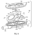
次に、図9を参照すると、差圧利用フローセンサ組立体900(図10と図11)用の使い捨て可能部分902の別の代替実施形態が図示してある。使い捨て可能部分902は、流体流入口906、上流流体チャンバ908、流体圧力膜910、フロー制限要素912、下流流体チャンバ914、流体流出口918を備える。後述する場合を除き、膜910は通常、不透過性である。使い捨て可能部分902は、基部920および蓋922を有する。
Referring now to FIG. 9, another alternative embodiment of a
図9に示すように、薬剤あるいは一部の他の流体は、流体流入口906を通って使い捨て可能部分902に流入する。薬剤は、流体流入口906から上流流体チャンバ908内に流入する。次に、薬剤はフロー制限要素912を通り、下流流体チャンバ914内へ流入する。フロー制限要素912を流れる薬剤の流れは、流体が上流流体チャンバ908からフロー制限要素912を通って下流流体チャンバ914へ流れる際に流体圧力の降下を生ずる。こうして、通常の状態での順方向への流体フロー中は、上流流体チャンバ908内の流体圧力は下流流体チャンバ914内の流体圧力を一般的に上回る。流体圧力膜910は、流入口906と流出口918の間の流体流路に沿って配置される。流体圧力膜910は、基本的には流体流路の壁を画定する。上流流体チャンバ908内の流体圧力は、流体圧力膜910の第1の領域911を押圧する。同様に、下流流体チャンバ914内の流体圧力が流体圧力膜910の第2の領域913を押圧する。
As shown in FIG. 9, the drug or some other fluid flows into the
蓋922が上流開口924と下流開口926を形成し、流体圧力膜910の第1と第2の領域911、913を再利用可能部分104の上流圧力センサ120と下流圧力センサ122とにそれぞれ連通させるようにできる。第1と第2の領域911、913は、開口924、926内に延出させるかあるいは好ましくは貫通させてセンサ120、122に係合させるよう、持ち上げることができる。第1と第2の領域911、913を持ち上げることは、組み立て中の蓋922と膜910の位置決めを追加的に支援する。
A
図9に示すように、流体圧力膜910は可撓性ダイヤフラム型膜である。流体圧力膜910は、シリコンやあるいは何らかの他の可撓性ポリマー材料あるいはエラストマー材料から形成することができる。図9中、膜910は、流体流路内へ延出する折り込みによりフランジを形成するかあるいは元々の成形形状のままのフランジを有する。フランジあるいは折り込みが、フロー制限要素912を受容する開口915を画定する。開口915は、膜910の第1の領域911と第2の領域913との間に配置する。孔917a、917bは、それぞれ開口915の両側壁を挿通している。フロー制限要素912は、流体圧力膜910の開口915内に配置されるよう適合させる。図12により明瞭に示されるように、フロー制限要素912はそこに貫通形成した開口930を有し、上流側と下流側の一方または両方の開口930周りにその中に形成される陥凹面928を随意選択的に有する。開口930は、流体が開口930内を流れる際に圧力降下を発生させ、上述したように流体の流量が測定できるようにする。図9に示した実施形態では、フロー制限要素は楔形状のプレートである。
As shown in FIG. 9, the
フロー制限要素912を一旦フロー制限膜910の受容開口915内に配置すると、基部920内に膜910を配置することができる。膜910は、開口915を収縮させフロー制限要素912を完全に取り囲むよう、折り込むかあるいは圧縮することができる。基部920には、フロー制限要素の受容開口915を含む膜910の一部を受容し案内し支持しかつ/または圧縮する少なくとも1個の直立ガイド、好ましくは一対の離間する直立ガイド931a、931bを含ませることができる。ガイド931a、931bはそれぞれ孔933a、933bを含んでおり、それらは組み付けた状態で膜の孔917a、917bおよびフロー制限要素912の開口930と連通する。蓋922は、基部920と蓋922との間に流体圧力膜910が位置決めされるよう位置決めする。蓋922と基部920を互いに超音波溶接し、図10に見られるように完全に組み付けられた使い捨て可能部分902を形成することができる。流体圧力膜910はこうして、基部920あるいは蓋922のいずれかに流体圧力膜910を係着する接着剤を一切使用せずに基部920と蓋922の間に確実に固定することができる。基部920あるいは蓋922のいずれかに流体圧力膜910を係着する必要性を排除したことで、使い捨て可能部分902の製造が簡単化される。フロー制限要素はまた、係着具、接着剤、精密加工組立技法を必要とすることなく流体流路沿いの適切な位置に流体密封態様にて固定される。
Once the
流体圧力膜910の開口915の両側壁の少なくとも一方は、その中に形成されてフロー制限要素912を受容するスロットあるいは陥凹950a、950b、932を随意選択的に有する。好ましくは、両側壁はフロー制限要素912を受容し位置決めし配向できるような大きさと形状と位置とを有するスロットあるいは陥凹950a、950b、932を含む。開口915を収縮させるべく膜910を折り込むかあるいは圧縮すると、スロットあるいは陥凹950a、950b、932はフロー制限要素912を完全に取り囲むよう適合させることができる。スロット950a、950bは、孔917a、917bに対しフロー制限要素912を位置決めし、使い捨て可能部分902の適切な流体流を保証するよう役立つ。スロットや陥凹部はまた、フロー制限要素912の周りにシールを形成するのを支援する。
At least one of the side walls of the
流体圧力膜910の一実施形態のより詳細な断面図が、図13に見て取れる。開口915における膜910の1つ以上の対向面が、フロー制限要素912を受容すべくその中に形成した陥凹932を有する。陥凹932は孔917a、917bと流体連通しており、膜910とフロー制限要素912を通って流体を流せるようにしている。陥凹932は、フロー制限要素912に対する位置決め(位置合わせと配向の両方を含む)をもたらす。陥凹932はまた、弾性可撓性膜の能力を高め、フロー制限要素周りに有効な流体シールを生み出す。流体圧力膜910はさらに、開口915の一側に配置した第1のリブ935aと、この第1のリブ935aとは反対側の開口915に位置する第2のリブ935bとを有する。リブ935a、935bは、膜910を折り込むかあるいは圧縮して開口915を収縮させたときに合一する。リブ935a、935bは、蓋922に対する流体圧力膜910の位置決めを支援するよう適合させてある。蓋922は、リブ935a、935bを受容し、使い捨て可能部分902の組み立て中に蓋922に対し移動する膜910の能力を制限するよう適合させた陥凹(図示せず)を持たせることができる。
A more detailed cross-sectional view of one embodiment of the
ここで図10と図11を参照すると、差圧利用流量センサ組立体900(図11)の構成を含め、使い捨て可能部分902と再利用可能部分104との関係が図示してある。使い捨て可能部分902は、概ね先に説明したのと同一の方式で再利用可能部分104と協働する。
Referring now to FIGS. 10 and 11, the relationship between the
図11に示すように、薬剤は流体流入口906を介して使い捨て可能部分902に流入する。薬剤は、流体流入口906から上流流体チャンバ908内に流入する。次に、薬剤はフロー制限要素912を通り、下流流体チャンバ914内へ流入する。フロー制限要素912を流れる薬剤の流れは、流体が上流流体チャンバ908からフロー制限要素912を通って下流流体チャンバ914内へ流れる際に流体圧力の降下に生ずる。こうして、通常の条件下での前進流体流の期間中、上流流体チャンバ908内の流体圧力は一般的に下流流体チャンバ914内の流体圧力を上回る。上流流体チャンバ908内の流体圧力が流体圧力膜910を押圧し、この膜910を蓋922の上流開口924を通過させて上流流体圧力センサ120を押圧させる。同様に、下流流体チャンバ914内の流体圧力が流体圧力膜910を押圧し、この膜910を蓋922の下流開口926を通過させ、下流流体圧力センサ122に押圧させる。
As shown in FIG. 11, the drug flows into the
使い捨て可能部分902の製造に様々な材料が利用できることが想到される。使い捨て可能部分902は、熱可塑材で構成することができる。フロー制限要素912を使い捨て可能部分902の残りの部分と同じ熱可塑材で作製するか、あるいは使い捨て可能部分902とは異なる材料にできることが想到される。フロー制限要素912を形成するよう利用することのできる材料の非限定的な例には、シリコン、ガラス、医用品質等級熱可塑材、エラストマーが含まれる。フロー制限要素912さえも、全部あるいは一部をステンレス鋼で作製することができる。ステンレス鋼オリフィス板は、熱可塑性フレームあるいはエラストマーフレーム内に収容することができる。流体圧力膜901は、TPEやシリコン等の様々なポリマー材料あるいはエラストマー材料で構成することができる。
It is envisioned that a variety of materials can be used to manufacture the
図4に関連して前述したように、差圧利用流量センサ組立体900の再利用可能部分104は回路基板124を用いて個々の圧力センサ120、122から受信した信号に基づき上流流体チャンバ908と下流流体圧力チャンバ914との間の差圧を算出し、あるいは回路基板124が上流チャンバ908と下流チャンバ914との間の差圧を算出する点滴ポンプ12等のプロセッサ付きの他の装置へ送信される出力信号を生成する。回路基板124の出力は、電気結線126を通って点滴ポンプ12(図1)へ送られる。
As described above in connection with FIG. 4, the
図14は、使い捨て可能部分1402のもう一つの代替実施形態を示す。使い捨て可能部分1402は、図9に示した使い捨て可能部分902と極めて類似するものである。事実、流体圧力膜1410と使い捨て可能部分1402のフロー制限要素1412だけが使い捨て可能部分902と異なる点が想到される。使い捨て可能部分1402の他の構成要素は使い捨て可能部分902のものと同一であるから、図9に関連して前述した説明がこれら構成要素に適用可能である。
FIG. 14 shows another alternative embodiment of the
流体圧力膜1410は、可撓性ダイヤフラム型の膜である。流体圧力膜1410は、シリコンや一部の他の可撓性ポリマー材料あるいはエラストマー材料から形成することができる。膜1410は、フロー制限要素1412を受容する開口1415を画定するフランジを折り込んで形成するかあるいは元々の成形形状のままのフランジを有する。フロー制限要素は、開口1430を有する。開口1430は、この開口1430を流体が流れる際に圧力降下を生ぜしめ、流体の流量が前述のように測定できるようにする。膜1410の開口1415は、膜1410の第1の領域1411と第2の領域1413との間に配置する。孔1417a、1417bは、それぞれ開口1415の両側壁を挿通して延在する。開口1415には、膜1410を折り込むか圧縮して開口1415を収縮させたときにフロー制限要素1412を受容して囲繞できるような大きさと位置とを与える。こうして、開口1415は膜1410を折り込むか圧縮したときにフロー制限要素1412を完全に囲い込む。フロー制限要素1412は、ステンレス鋼板等の薄いプレートとすることができるが、他材料を使用することもできる。フロー制限要素1412は、一実施形態では好ましくは実質平坦もしくは平面的とする。フロー制限要素1412の薄さは、膜1410を折り込むかあるいは圧縮して開口1415を収縮させるときに、膜1410とフロー制限要素1412との間の流体密封シールの形成を支援する。フロー制限要素1412は、このフロー制限要素1412の周りにシールを形成することを支援すべく膜1410の開口1415の近傍にスロットも陥凹も一切不要であるほどに薄くする。
The
流体制限膜910内の開口915あるいは折り込みを内転させ、フロー制限要素912を受容できることが想到される。フロー制限要素912を受容すべく基部920内あるいは基部と膜910の両方の中にスロットあるいは開口915が配設できることもまた、想到される。
It is envisioned that an
前述した内容は最良の態様および/または他の実施例と見なされるものを説明したものであるが、様々な改変が可能であり、本明細書に開示した主題が様々な形態と実施例とで実施することができ、その一部しか本明細書に説明してこなかった数多くの他の応用例や組み合わせや環境において適用できることは理解されたい。当業者は、主題範囲から逸脱することなく開示態様を変更しあるいは補正できることを認識されたい。その結果、主題は具体的細部や提出内容や本説明中の例示実施例には限定はされない。本明細書に開示した好都合な概念の真正な範囲に含まれるありとあらゆる改変例と変形例を保護することを、意図するものである。 While the foregoing describes what is considered to be the best mode and / or other embodiments, various modifications are possible and the subject matter disclosed herein may be embodied in various forms and embodiments. It should be understood that the invention can be implemented and applied in many other applications, combinations and environments, only some of which have been described herein. Those skilled in the art will recognize that the disclosed aspects can be altered or corrected without departing from the scope of the subject matter. As a result, the subject matter is not limited to specific details, submissions, or illustrative examples in the present description. It is intended to protect any and all modifications and variations that fall within the true scope of the advantageous concepts disclosed herein.
Claims (29)
使い捨て可能部分で、
流入口と流出口を形成する流体流路を画定し、基部と蓋部を有する本体と、
流入口と流出口との間の流体流路に沿って配置され、本体の基部と蓋部との間に固定された可撓性流体圧力膜と、
流入口と流出口との間の流体流路内に位置決めしたフロー制限要素とを有し、
蓋部が第1の開口と第2の開口を有し、流体圧力膜が蓋部の第1の開口と第2の開口にそれぞれ位置合わせするよう適合させた第1の領域と第2の領域を有し、
流体圧力膜が第1の領域と第2の領域の間にフロー制限要素を受容する開口を画定する使い捨て可能部分と、
再利用可能部分で、
流体流路の外側に配設され、流入口とフロー制限要素との間の流体流路内の上流箇所で上流流体圧力を検出するために、蓋部の第1の開口を通して流体圧力膜の第1の領域によって押圧されるように構成された、上流流体圧力センサと、
流体流路の外側に配設され、フロー制限要素と流出口との間の流体流路内の下流箇所で下流流体圧力を検出するために、蓋部の第2の開口を通して流体圧力膜の第2の領域によって押圧されるように構成された、下流流体圧力センサとを有する再利用可能部分とを備える、差圧利用フローセンサ組立体。 A differential pressure based flow sensor assembly for measuring the flow rate of a fluid system, comprising:
A disposable part,
A body defining a fluid flow path forming an inlet and an outlet and having a base and a lid;
A flexible fluid pressure membrane disposed along the fluid flow path between the inlet and the outlet and secured between the base and lid of the body;
A flow restricting element positioned in the fluid flow path between the inlet and the outlet,
A first region and a second region, wherein the lid portion has a first opening and a second opening, and the fluid pressure film is adapted to align with the first opening and the second opening of the lid portion, respectively. Have
A disposable portion wherein the fluid pressure membrane defines an opening for receiving a flow restricting element between the first region and the second region ;
In the reusable part,
A fluid pressure membrane first disposed through the first opening of the lid for detecting upstream fluid pressure at an upstream location in the fluid flow path between the inlet and the flow restricting element , disposed outside the fluid flow path . An upstream fluid pressure sensor configured to be pressed by one region ;
A fluid pressure membrane first disposed through the second opening of the lid for detecting downstream fluid pressure at a downstream location in the fluid flow path between the flow restricting element and the outlet , disposed outside the fluid flow path . And a reusable part having a downstream fluid pressure sensor configured to be pressed by two regions .
基部に固定された蓋部を有し、蓋部が第1開口及び第2の開口を有する、流入口と流出口とを形成する流体流路を画定する本体と、
流入口と流出口との間の流体流路中に位置決めしたフロー制限要素と、
流入口と流出口の間の流体流路に沿って配設され、本体の蓋部と基部の間に固定された、フロー制限要素を受容する開口を画定している可撓性流体圧力膜とを備え、フロー制限要素を受容する開口が、蓋部の第1の開口に整列する膜の第1の領域と蓋部の第2の開口に整列する膜の第2の領域との間に位置している、使い捨て可能組立体。 A disposable assembly for use with a differential pressure based fluid flow sensor assembly comprising:
A body defining a fluid flow path having a lid fixed to the base, the lid portion has a first opening and the second opening, forming an inlet and an outlet,
A flow restricting element positioned in the fluid flow path between the inlet and the outlet;
A flexible fluid pressure membrane disposed along the fluid flow path between the inlet and outlet and secured between the lid and base of the body and defining an opening for receiving a flow restricting element; And the opening for receiving the flow restricting element is located between a first region of the membrane aligned with the first opening of the lid and a second region of the membrane aligned with the second opening of the lid A disposable assembly.
基部、蓋部、フロー制限要素、可撓性流体圧力膜を設けるステップと、
流体圧力膜にフロー制限要素を受容するための開口を形成するステップと、
フロー制限要素を開口に挿入するステップと、
流体圧力膜とフロー制限要素とを基部と蓋部との間に位置決めするステップと、
基部に蓋部を固定するステップとを含む、方法。 A method of forming a disposable flow sensor assembly comprising:
Providing a base, a lid, a flow restricting element, a flexible fluid pressure membrane;
A step that forms form an opening for receiving a flow restricting element in the flow body pressure membranes,
Inserting a flow restricting element into the opening;
Positioning the fluid pressure membrane and the flow restricting element between the base and the lid;
Securing the lid to the base.
Applications Claiming Priority (5)
| Application Number | Priority Date | Filing Date | Title |
|---|---|---|---|
| US5560508P | 2008-05-23 | 2008-05-23 | |
| US61/055,605 | 2008-05-23 | ||
| US12/468,994 US8065924B2 (en) | 2008-05-23 | 2009-05-20 | Cassette for differential pressure based medication delivery flow sensor assembly for medication delivery monitoring and method of making the same |
| US12/468,994 | 2009-05-20 | ||
| PCT/US2009/044827 WO2009143336A1 (en) | 2008-05-23 | 2009-05-21 | Cassette for differential pressure based medication delivery flow sensor assembly for medication delivery monitoring and method of making the same |
Publications (3)
| Publication Number | Publication Date |
|---|---|
| JP2011520572A JP2011520572A (en) | 2011-07-21 |
| JP2011520572A5 JP2011520572A5 (en) | 2012-07-05 |
| JP5319761B2 true JP5319761B2 (en) | 2013-10-16 |
Family
ID=41340549
Family Applications (1)
| Application Number | Title | Priority Date | Filing Date |
|---|---|---|---|
| JP2011510701A Active JP5319761B2 (en) | 2008-05-23 | 2009-05-21 | Cassette for differential-pressure-based drug administration flow sensor assembly for monitoring drug administration and method for making the same |
Country Status (7)
| Country | Link |
|---|---|
| US (1) | US8065924B2 (en) |
| EP (1) | EP2296725B1 (en) |
| JP (1) | JP5319761B2 (en) |
| AU (1) | AU2009249016B2 (en) |
| CA (1) | CA2725079C (en) |
| ES (1) | ES2807229T3 (en) |
| WO (1) | WO2009143336A1 (en) |
Families Citing this family (28)
| Publication number | Priority date | Publication date | Assignee | Title |
|---|---|---|---|---|
| US20100114027A1 (en) * | 2008-11-05 | 2010-05-06 | Hospira, Inc. | Fluid medication delivery systems for delivery monitoring of secondary medications |
| US8048022B2 (en) * | 2009-01-30 | 2011-11-01 | Hospira, Inc. | Cassette for differential pressure based medication delivery flow sensor assembly for medication delivery monitoring and method of making the same |
| US9039655B2 (en) | 2009-11-06 | 2015-05-26 | Crisi Medical Systems, Inc. | Medication injection site and data collection system |
| US9101534B2 (en) | 2010-04-27 | 2015-08-11 | Crisi Medical Systems, Inc. | Medication and identification information transfer apparatus |
| US10492991B2 (en) | 2010-05-30 | 2019-12-03 | Crisi Medical Systems, Inc. | Medication container encoding, verification, and identification |
| US9514131B1 (en) | 2010-05-30 | 2016-12-06 | Crisi Medical Systems, Inc. | Medication container encoding, verification, and identification |
| US9139316B2 (en) | 2010-12-29 | 2015-09-22 | Cardinal Health 414, Llc | Closed vial fill system for aseptic dispensing |
| US9078809B2 (en) | 2011-06-16 | 2015-07-14 | Crisi Medical Systems, Inc. | Medication dose preparation and transfer system |
| US9744298B2 (en) | 2011-06-22 | 2017-08-29 | Crisi Medical Systems, Inc. | Selectively controlling fluid flow through a fluid pathway |
| US10293107B2 (en) | 2011-06-22 | 2019-05-21 | Crisi Medical Systems, Inc. | Selectively Controlling fluid flow through a fluid pathway |
| US9417332B2 (en) | 2011-07-15 | 2016-08-16 | Cardinal Health 414, Llc | Radiopharmaceutical CZT sensor and apparatus |
| US20130020727A1 (en) | 2011-07-15 | 2013-01-24 | Cardinal Health 414, Llc. | Modular cassette synthesis unit |
| WO2013012822A1 (en) | 2011-07-15 | 2013-01-24 | Cardinal Health 414, Llc | Systems, methods, and devices for producing, manufacturing, and control of radiopharmaceuticals |
| US9101712B2 (en) | 2012-03-09 | 2015-08-11 | Zevex, Inc. | Occlusion detection method |
| US10143830B2 (en) | 2013-03-13 | 2018-12-04 | Crisi Medical Systems, Inc. | Injection site information cap |
| DE102013106582A1 (en) * | 2013-06-24 | 2014-12-24 | Ulrich Gmbh & Co. Kg | Pressure measuring cell for use in an infusion or injection system |
| DE102013213390A1 (en) * | 2013-07-09 | 2015-01-15 | Rwth Aachen | Method and device for detecting an aspiration of a withdrawal cannula |
| US20150133861A1 (en) | 2013-11-11 | 2015-05-14 | Kevin P. McLennan | Thermal management system and method for medical devices |
| US10143795B2 (en) | 2014-08-18 | 2018-12-04 | Icu Medical, Inc. | Intravenous pole integrated power, control, and communication system and method for an infusion pump |
| US9776757B2 (en) | 2014-10-10 | 2017-10-03 | Becton, Dickinson And Company | Syringe labeling device |
| WO2016057756A1 (en) | 2014-10-10 | 2016-04-14 | Becton, Dickinson And Company | Substrate tensioning control device |
| AU2016267763B2 (en) | 2015-05-26 | 2021-07-08 | Icu Medical, Inc. | Disposable infusion fluid delivery device for programmable large volume drug delivery |
| BR112019012214A8 (en) | 2016-12-15 | 2023-03-28 | Baxter Int | SYSTEM AND METHOD FOR MONITORING AND DETERMINING PATIENT PARAMETERS FROM DETECTED VENOUS WAVEFORM |
| US10809139B2 (en) * | 2018-02-14 | 2020-10-20 | Carefusion 303, Inc. | Integrated sensor to monitor fluid delivery |
| US11039754B2 (en) | 2018-05-14 | 2021-06-22 | Baxter International Inc. | System and method for monitoring and determining patient parameters from sensed venous waveform |
| CN113905775A (en) * | 2019-04-16 | 2022-01-07 | 英福森创新有限责任公司 | Sensor array |
| USD939079S1 (en) | 2019-08-22 | 2021-12-21 | Icu Medical, Inc. | Infusion pump |
| WO2023048710A1 (en) * | 2021-09-22 | 2023-03-30 | Carefusion 303, Inc. | Interlocked sensor assembly for infusion system |
Family Cites Families (103)
| Publication number | Priority date | Publication date | Assignee | Title |
|---|---|---|---|---|
| US4195515A (en) | 1976-06-28 | 1980-04-01 | Smoll Owen C | In line electromagnetic flow measurement transducer |
| SE421349B (en) | 1977-12-16 | 1981-12-14 | Graende Per Olof | FLOOD METERS FOR REGISTERING REAL LOSS OF PULSED FLUID FLUID |
| US4261356A (en) | 1978-10-23 | 1981-04-14 | Baxter Travenol Laboratories, Inc. | Method and apparatus for controlling the dispensing of fluid |
| US4343316A (en) | 1980-05-16 | 1982-08-10 | C. R. Bard, Inc. | Electronic urine flow monitor |
| US4613325A (en) * | 1982-07-19 | 1986-09-23 | Abrams Lawrence M | Flow rate sensing device |
| IT1180107B (en) | 1984-11-05 | 1987-09-23 | Greg Di S Greganti E C Sas | DEVICE FOR REPORTING ABNORMAL PRESSURE CONDITIONS IN A MOTOR VEHICLE TIRE |
| US4626244A (en) | 1985-02-01 | 1986-12-02 | Consolidated Controls Corporation | Implantable medication infusion device |
| US4626243A (en) * | 1985-06-21 | 1986-12-02 | Applied Biomedical Corporation | Gravity-independent infusion system |
| US4683916A (en) * | 1986-09-25 | 1987-08-04 | Burron Medical Inc. | Normally closed automatic reflux valve |
| US4758228A (en) | 1986-11-17 | 1988-07-19 | Centaur Sciences, Inc. | Medical infusion pump with sensors |
| US4856339A (en) | 1986-11-17 | 1989-08-15 | Centaur Sciences, Inc. | Medical infusion pump with sensors |
| US5211626A (en) | 1987-05-01 | 1993-05-18 | Product Innovation Holdings Ltd. | Medical infusion apparatus |
| EP0329804B1 (en) | 1988-02-24 | 1992-06-17 | Dorr-Oliver Incorporated | Vacuum filter with detachable jammed sealing tape |
| US4947856A (en) | 1988-10-26 | 1990-08-14 | Abbott Laboratories | Fluid pressure monitoring and flow control apparatus |
| US4881413A (en) | 1988-10-31 | 1989-11-21 | Bio-Medicus, Inc. | Blood flow detection device |
| US4938079A (en) | 1989-03-06 | 1990-07-03 | Ivac Corporation | Thermal transit time flow measurement system |
| US5242406A (en) | 1990-10-19 | 1993-09-07 | Sil Medics Ltd. | Liquid delivery device particularly useful for delivering drugs |
| JPH04138228U (en) * | 1991-06-18 | 1992-12-24 | 富士ロビン株式会社 | Coupling with differential pressure detection function |
| US5287851A (en) | 1991-09-11 | 1994-02-22 | Beran Anthony V | Endotracheal tube connector with integral pneumotach transducer |
| JP3182807B2 (en) * | 1991-09-20 | 2001-07-03 | 株式会社日立製作所 | Multifunctional fluid measurement transmission device and fluid volume measurement control system using the same |
| US6358239B1 (en) | 1992-01-24 | 2002-03-19 | I-Flow Corporation | Platen pump |
| US6090071A (en) * | 1992-04-17 | 2000-07-18 | Science Incorporated | Fluid dispenser with fill adapter |
| US6068615A (en) | 1994-07-22 | 2000-05-30 | Health Hero Network, Inc. | Inductance-based dose measurement in syringes |
| US5292306A (en) | 1993-01-29 | 1994-03-08 | Abbott Laboratories | Method of detecting occlusions in a solution pumping system |
| US5325728A (en) | 1993-06-22 | 1994-07-05 | Medtronic, Inc. | Electromagnetic flow meter |
| US5417395A (en) | 1993-06-30 | 1995-05-23 | Medex, Inc. | Modular interconnecting component support plate |
| WO1997001364A1 (en) | 1993-06-30 | 1997-01-16 | Medex, Inc. | Medical pressure transducer with sliding components |
| ATE209052T1 (en) | 1993-06-30 | 2001-12-15 | Hamilton Co | MANUAL DISPENSING AID FOR AN INJECTION SYRINGE |
| US6385505B1 (en) | 1993-07-21 | 2002-05-07 | Omnicell.Com | Methods and apparatus for dispensing items |
| US6272394B1 (en) | 1993-07-21 | 2001-08-07 | Omnicell.Com | Methods and apparatus for dispensing items |
| US5417119A (en) | 1994-01-07 | 1995-05-23 | Smoll; Owen C. | Dual electromagnet partially disposable fluid flow transducer with side-by-side electrodes |
| US5463906A (en) | 1994-01-24 | 1995-11-07 | Triton Technology, Inc. | Interchangeable disposable acoustic for use with an ultrasonic flowmeter, particularly during extracorporeal measurement of blood flow |
| US5536249A (en) | 1994-03-09 | 1996-07-16 | Visionary Medical Products, Inc. | Pen-type injector with a microprocessor and blood characteristic monitor |
| JP3628699B2 (en) | 1994-05-13 | 2005-03-16 | アボツト・ラボラトリーズ | Disposable infusion pumping chamber cassette with push button flow stopper thereon |
| JP3171017B2 (en) * | 1994-08-22 | 2001-05-28 | 横河電機株式会社 | Flowmeter |
| US5450758A (en) | 1994-09-23 | 1995-09-19 | Smoll; Owen C. | Bioprobe replacement sensor and transducer |
| US6760643B2 (en) | 1994-10-11 | 2004-07-06 | Omnicell, Inc. | Methods and apparatus for dispensing items |
| US5962794A (en) * | 1995-05-01 | 1999-10-05 | Science Incorporated | Fluid delivery apparatus with reservior fill assembly |
| US5891051A (en) | 1995-06-02 | 1999-04-06 | C.R. Bard, Inc. | Electronic urine monitor |
| US5651775A (en) | 1995-07-12 | 1997-07-29 | Walker; Richard Bradley | Medication delivery and monitoring system and methods |
| US5697916A (en) | 1995-11-21 | 1997-12-16 | Stat Medical Devices Inc. | Hypodermic dosage measuring device |
| US5551300A (en) * | 1995-12-18 | 1996-09-03 | Abbott Laboratories | User-restricted passage in reusable portion of device for monitoring a physiological pressure |
| US5628309A (en) | 1996-01-25 | 1997-05-13 | Raya Systems, Inc. | Meter for electrically measuring and recording injection syringe doses |
| US5672832A (en) | 1996-02-15 | 1997-09-30 | Nt International, Inc. | Chemically inert flow meter within caustic fluids having non-contaminating body |
| US5758643A (en) | 1996-07-29 | 1998-06-02 | Via Medical Corporation | Method and apparatus for monitoring blood chemistry |
| US6272934B1 (en) | 1996-09-18 | 2001-08-14 | Alberta Research Council Inc. | Multi-phase fluid flow measurement apparatus and method |
| US5947911A (en) | 1997-01-09 | 1999-09-07 | Via Medical Corporation | Method and apparatus for reducing purge volume in a blood chemistry monitoring system |
| JPH10239193A (en) * | 1997-02-25 | 1998-09-11 | Nitta Ind Corp | Pressure sensor |
| US6700174B1 (en) | 1997-09-25 | 2004-03-02 | Integrated Micromachines, Inc. | Batch fabricated semiconductor thin-film pressure sensor and method of making same |
| US6270455B1 (en) | 1997-03-28 | 2001-08-07 | Health Hero Network, Inc. | Networked system for interactive communications and remote monitoring of drug delivery |
| US5944660A (en) | 1997-07-08 | 1999-08-31 | Optical Sensors Incorporated | Disposable cartridge assembly with optional integrated temperature control system, and systems containing same |
| US5904666A (en) | 1997-08-18 | 1999-05-18 | L.Vad Technology, Inc. | Method and apparatus for measuring flow rate and controlling delivered volume of fluid through a valve aperture |
| US6076392A (en) | 1997-08-18 | 2000-06-20 | Metasensors, Inc. | Method and apparatus for real time gas analysis |
| US6032536A (en) | 1998-09-28 | 2000-03-07 | Xerox Corporation | Pressure sensor and method for detecting pressure |
| US6152162A (en) | 1998-10-08 | 2000-11-28 | Mott Metallurgical Corporation | Fluid flow controlling |
| DE19900937A1 (en) | 1999-01-13 | 2000-07-20 | Ulrich Gmbh & Co Kg | Injector for the application of liquids with a pressure measuring system |
| DE29904864U1 (en) | 1999-03-17 | 2000-08-03 | B. Braun Melsungen Ag, 34212 Melsungen | Injection device with a pen |
| US6349740B1 (en) | 1999-04-08 | 2002-02-26 | Abbott Laboratories | Monolithic high performance miniature flow control unit |
| JP2001015739A (en) * | 1999-06-30 | 2001-01-19 | Nec Corp | Gate insulated film and manufacture thereof |
| US6277099B1 (en) | 1999-08-06 | 2001-08-21 | Becton, Dickinson And Company | Medication delivery pen |
| US6578435B2 (en) | 1999-11-23 | 2003-06-17 | Nt International, Inc. | Chemically inert flow control with non-contaminating body |
| US6386050B1 (en) | 1999-12-21 | 2002-05-14 | Agilent Technologies, Inc. | Non-invasive fluid flow sensing based on injected heat tracers and indirect temperature monitoring |
| CA2403384C (en) | 2000-03-22 | 2007-04-10 | Docusys, Inc. | A drug delivery and monitoring system |
| US6445053B1 (en) | 2000-07-28 | 2002-09-03 | Abbott Laboratories | Micro-machined absolute pressure sensor |
| US6685668B1 (en) | 2000-07-31 | 2004-02-03 | Abbott Laboratories | Closed-loop IV fluid flow control |
| US6589229B1 (en) * | 2000-07-31 | 2003-07-08 | Becton, Dickinson And Company | Wearable, self-contained drug infusion device |
| US6609431B1 (en) | 2000-09-29 | 2003-08-26 | Xellogy, Inc. | Flow measuring device based on predetermine class of liquid |
| AU2002225793A1 (en) | 2000-11-29 | 2002-06-11 | Docusys, Inc. | Drug delivery device incorporating a tracking code |
| CA2454370C (en) | 2001-08-31 | 2008-02-19 | Docusys, Inc. | System and method for displaying drug information |
| WO2003030724A2 (en) | 2001-10-12 | 2003-04-17 | University Of Utah Research Foundation | Anesthesia drug monitor |
| US6920795B2 (en) | 2002-01-09 | 2005-07-26 | Red Wing Technologies, Inc. | Adapter for coupling a sensor to a fluid line |
| USD481121S1 (en) | 2002-01-10 | 2003-10-21 | Docusys, Inc. | Syringe label cradle |
| ATE402724T1 (en) * | 2002-02-18 | 2008-08-15 | Danfoss As | DEVICE FOR ADMINISTRATION OF A MEDICATION IN LIQUID FORM |
| US6932796B2 (en) | 2002-05-15 | 2005-08-23 | Tearafuse, Inc. | Liquid metering system |
| US20030236489A1 (en) * | 2002-06-21 | 2003-12-25 | Baxter International, Inc. | Method and apparatus for closed-loop flow control system |
| US6975922B2 (en) | 2003-05-08 | 2005-12-13 | Omnicell, Inc. | Secured dispensing cabinet and methods |
| US20040232219A1 (en) | 2003-05-20 | 2004-11-25 | Fowler Timothy Charles | Medical treatment and prescription administration verification method |
| US6813964B1 (en) | 2003-05-21 | 2004-11-09 | Hospira, Inc. | Fluid flow measurement device |
| US20040251406A1 (en) | 2003-06-16 | 2004-12-16 | Robert Figueria | Micro-sized tilt sensor |
| US7131451B2 (en) * | 2003-09-04 | 2006-11-07 | Rivatek Incorporated | Apparatus for controlling and metering fluid flow |
| US6935192B2 (en) | 2003-09-30 | 2005-08-30 | Agilent Technologies, Inc. | Microfluidic bulk flow determinations based on converting heat tracer measurements |
| US7284966B2 (en) * | 2003-10-01 | 2007-10-23 | Agency For Science, Technology & Research | Micro-pump |
| DE10350422A1 (en) | 2003-10-29 | 2005-06-16 | Arzneimittel Gmbh Apotheker Vetter & Co. Ravensburg | Method for identifying and / or testing and / or releasing in particular pre-filled medical syringes prior to their use, and test device for carrying out the method |
| JP2005265819A (en) | 2004-02-19 | 2005-09-29 | Keyence Corp | Shunting-type flow sensor device |
| EP1720601A4 (en) | 2004-02-20 | 2010-03-24 | Fluidnet Corp | Automated fluid flow control system |
| US7503903B2 (en) | 2004-02-20 | 2009-03-17 | Fluidnet Corporation | Automated fluid flow control system |
| US20050209563A1 (en) * | 2004-03-19 | 2005-09-22 | Peter Hopping | Cassette-based dialysis medical fluid therapy systems, apparatuses and methods |
| FR2870718B1 (en) | 2004-05-25 | 2006-09-22 | Spine Next Sa | TREATMENT ASSEMBLY FOR THE DEGENERATION OF AN INTERVERTEBRAL DISC |
| US7096729B2 (en) | 2004-06-08 | 2006-08-29 | Honeywell International Inc. | Disposable fluid flow sensor |
| US7159468B2 (en) * | 2004-06-15 | 2007-01-09 | Halliburton Energy Services, Inc. | Fiber optic differential pressure sensor |
| US20060181695A1 (en) | 2005-02-11 | 2006-08-17 | Sage Burton H Jr | Compensating liquid delivery system and method |
| US20060189926A1 (en) | 2005-02-14 | 2006-08-24 | Hall W D | Apparatus and methods for analyzing body fluid samples |
| US20060260416A1 (en) | 2005-05-19 | 2006-11-23 | Sage Burton H | Flow metering system |
| US20070129618A1 (en) | 2005-06-20 | 2007-06-07 | Daniel Goldberger | Blood parameter testing system |
| US7415895B2 (en) | 2005-08-26 | 2008-08-26 | Smc Kabushiki Kaisha | Flow meter with a rectifying module having a plurality of mesh members |
| JP5083853B2 (en) | 2005-09-07 | 2012-11-28 | 愛知時計電機株式会社 | Electromagnetic flow meter |
| US7162290B1 (en) | 2005-09-16 | 2007-01-09 | Palco Labs, Inc. | Method and apparatus for blood glucose testing from a reversible infusion line |
| US20070179435A1 (en) | 2005-12-21 | 2007-08-02 | Braig James R | Analyte detection system with periodic sample draw and body fluid analyzer |
| US7162927B1 (en) | 2005-12-16 | 2007-01-16 | Honeywell International Inc. | Design of a wet/wet amplified differential pressure sensor based on silicon piezoresistive technology |
| US7261003B2 (en) * | 2006-01-03 | 2007-08-28 | Freescale Semiconductor, Inc. | Flowmeter and method for the making thereof |
| US7944008B2 (en) | 2007-04-23 | 2011-05-17 | Sierra Scientific Instruments, Llc | Suspended membrane pressure sensing array |
| US8403908B2 (en) | 2007-12-17 | 2013-03-26 | Hospira, Inc. | Differential pressure based flow sensor assembly for medication delivery monitoring and method of using the same |
| US8048022B2 (en) | 2009-01-30 | 2011-11-01 | Hospira, Inc. | Cassette for differential pressure based medication delivery flow sensor assembly for medication delivery monitoring and method of making the same |
-
2009
- 2009-05-20 US US12/468,994 patent/US8065924B2/en active Active
- 2009-05-21 EP EP09751564.7A patent/EP2296725B1/en active Active
- 2009-05-21 JP JP2011510701A patent/JP5319761B2/en active Active
- 2009-05-21 WO PCT/US2009/044827 patent/WO2009143336A1/en active Application Filing
- 2009-05-21 AU AU2009249016A patent/AU2009249016B2/en active Active
- 2009-05-21 ES ES09751564T patent/ES2807229T3/en active Active
- 2009-05-21 CA CA2725079A patent/CA2725079C/en active Active
Also Published As
| Publication number | Publication date |
|---|---|
| US20090288497A1 (en) | 2009-11-26 |
| EP2296725B1 (en) | 2020-06-24 |
| WO2009143336A1 (en) | 2009-11-26 |
| ES2807229T3 (en) | 2021-02-22 |
| JP2011520572A (en) | 2011-07-21 |
| EP2296725A1 (en) | 2011-03-23 |
| CA2725079A1 (en) | 2009-11-26 |
| EP2296725A4 (en) | 2017-08-09 |
| AU2009249016A1 (en) | 2009-11-26 |
| CA2725079C (en) | 2015-10-27 |
| US8065924B2 (en) | 2011-11-29 |
| AU2009249016B2 (en) | 2014-07-17 |
Similar Documents
| Publication | Publication Date | Title |
|---|---|---|
| JP5319761B2 (en) | Cassette for differential-pressure-based drug administration flow sensor assembly for monitoring drug administration and method for making the same | |
| AU2008338449B2 (en) | Differential pressure based flow sensor assembly for medication delivery monitoring and method of using the same | |
| US20100114027A1 (en) | Fluid medication delivery systems for delivery monitoring of secondary medications | |
| AU2009345108B2 (en) | System and method for delivering and monitoring medication | |
| US7819838B2 (en) | Cassette for use in a medication delivery flow sensor assembly and method of making the same | |
| JP5134142B2 (en) | Apparatus and method for measuring at least one flow parameter | |
| AU2009338734B2 (en) | Cassette for differential pressure based flow sensor assembly |
Legal Events
| Date | Code | Title | Description |
|---|---|---|---|
| A521 | Request for written amendment filed |
Free format text: JAPANESE INTERMEDIATE CODE: A523 Effective date: 20120521 |
|
| A621 | Written request for application examination |
Free format text: JAPANESE INTERMEDIATE CODE: A621 Effective date: 20120521 |
|
| A977 | Report on retrieval |
Free format text: JAPANESE INTERMEDIATE CODE: A971007 Effective date: 20130625 |
|
| TRDD | Decision of grant or rejection written | ||
| A01 | Written decision to grant a patent or to grant a registration (utility model) |
Free format text: JAPANESE INTERMEDIATE CODE: A01 Effective date: 20130702 |
|
| A61 | First payment of annual fees (during grant procedure) |
Free format text: JAPANESE INTERMEDIATE CODE: A61 Effective date: 20130711 |
|
| R150 | Certificate of patent or registration of utility model |
Ref document number: 5319761 Country of ref document: JP Free format text: JAPANESE INTERMEDIATE CODE: R150 Free format text: JAPANESE INTERMEDIATE CODE: R150 |
|
| R250 | Receipt of annual fees |
Free format text: JAPANESE INTERMEDIATE CODE: R250 |
|
| S111 | Request for change of ownership or part of ownership |
Free format text: JAPANESE INTERMEDIATE CODE: R313113 |
|
| S531 | Written request for registration of change of domicile |
Free format text: JAPANESE INTERMEDIATE CODE: R313531 |
|
| S533 | Written request for registration of change of name |
Free format text: JAPANESE INTERMEDIATE CODE: R313533 |
|
| R350 | Written notification of registration of transfer |
Free format text: JAPANESE INTERMEDIATE CODE: R350 |
|
| R250 | Receipt of annual fees |
Free format text: JAPANESE INTERMEDIATE CODE: R250 |
|
| R250 | Receipt of annual fees |
Free format text: JAPANESE INTERMEDIATE CODE: R250 |
|
| R250 | Receipt of annual fees |
Free format text: JAPANESE INTERMEDIATE CODE: R250 |
|
| R250 | Receipt of annual fees |
Free format text: JAPANESE INTERMEDIATE CODE: R250 |
|
| R250 | Receipt of annual fees |
Free format text: JAPANESE INTERMEDIATE CODE: R250 |
|
| R250 | Receipt of annual fees |
Free format text: JAPANESE INTERMEDIATE CODE: R250 |
|
| R250 | Receipt of annual fees |
Free format text: JAPANESE INTERMEDIATE CODE: R250 |