JP5318122B2 - Method and apparatus for reading information contained in bar code - Google Patents
Method and apparatus for reading information contained in bar code Download PDFInfo
- Publication number
- JP5318122B2 JP5318122B2 JP2010547197A JP2010547197A JP5318122B2 JP 5318122 B2 JP5318122 B2 JP 5318122B2 JP 2010547197 A JP2010547197 A JP 2010547197A JP 2010547197 A JP2010547197 A JP 2010547197A JP 5318122 B2 JP5318122 B2 JP 5318122B2
- Authority
- JP
- Japan
- Prior art keywords
- image
- barcode
- region
- filter
- gradient
- Prior art date
- Legal status (The legal status is an assumption and is not a legal conclusion. Google has not performed a legal analysis and makes no representation as to the accuracy of the status listed.)
- Expired - Fee Related
Links
Images


Classifications
-
- G—PHYSICS
- G06—COMPUTING; CALCULATING OR COUNTING
- G06K—GRAPHICAL DATA READING; PRESENTATION OF DATA; RECORD CARRIERS; HANDLING RECORD CARRIERS
- G06K7/00—Methods or arrangements for sensing record carriers, e.g. for reading patterns
- G06K7/10—Methods or arrangements for sensing record carriers, e.g. for reading patterns by electromagnetic radiation, e.g. optical sensing; by corpuscular radiation
- G06K7/14—Methods or arrangements for sensing record carriers, e.g. for reading patterns by electromagnetic radiation, e.g. optical sensing; by corpuscular radiation using light without selection of wavelength, e.g. sensing reflected white light
- G06K7/1404—Methods for optical code recognition
- G06K7/146—Methods for optical code recognition the method including quality enhancement steps
- G06K7/1465—Methods for optical code recognition the method including quality enhancement steps using several successive scans of the optical code
-
- G—PHYSICS
- G06—COMPUTING; CALCULATING OR COUNTING
- G06K—GRAPHICAL DATA READING; PRESENTATION OF DATA; RECORD CARRIERS; HANDLING RECORD CARRIERS
- G06K7/00—Methods or arrangements for sensing record carriers, e.g. for reading patterns
- G06K7/10—Methods or arrangements for sensing record carriers, e.g. for reading patterns by electromagnetic radiation, e.g. optical sensing; by corpuscular radiation
- G06K7/14—Methods or arrangements for sensing record carriers, e.g. for reading patterns by electromagnetic radiation, e.g. optical sensing; by corpuscular radiation using light without selection of wavelength, e.g. sensing reflected white light
- G06K7/1404—Methods for optical code recognition
- G06K7/1439—Methods for optical code recognition including a method step for retrieval of the optical code
- G06K7/1443—Methods for optical code recognition including a method step for retrieval of the optical code locating of the code in an image
-
- G—PHYSICS
- G06—COMPUTING; CALCULATING OR COUNTING
- G06K—GRAPHICAL DATA READING; PRESENTATION OF DATA; RECORD CARRIERS; HANDLING RECORD CARRIERS
- G06K7/00—Methods or arrangements for sensing record carriers, e.g. for reading patterns
- G06K7/10—Methods or arrangements for sensing record carriers, e.g. for reading patterns by electromagnetic radiation, e.g. optical sensing; by corpuscular radiation
- G06K7/14—Methods or arrangements for sensing record carriers, e.g. for reading patterns by electromagnetic radiation, e.g. optical sensing; by corpuscular radiation using light without selection of wavelength, e.g. sensing reflected white light
- G06K7/1404—Methods for optical code recognition
- G06K7/1439—Methods for optical code recognition including a method step for retrieval of the optical code
- G06K7/1456—Methods for optical code recognition including a method step for retrieval of the optical code determining the orientation of the optical code with respect to the reader and correcting therefore
Landscapes
- Engineering & Computer Science (AREA)
- Physics & Mathematics (AREA)
- Toxicology (AREA)
- Health & Medical Sciences (AREA)
- Electromagnetism (AREA)
- General Health & Medical Sciences (AREA)
- Artificial Intelligence (AREA)
- Computer Vision & Pattern Recognition (AREA)
- General Physics & Mathematics (AREA)
- Theoretical Computer Science (AREA)
- Quality & Reliability (AREA)
- Studio Devices (AREA)
- Image Analysis (AREA)
Description
本発明は概して、バーコードに含まれている情報を読み出す分野に関する。 The present invention relates generally to the field of reading information contained in bar codes.
バーコードは情報の、コンピュータで読取り可能な表現である。バーコードは一般に製品の識別と製品に関する情報の伝達との少なくともいずれかに用いられる。 A bar code is a computer readable representation of information. The bar code is generally used for product identification and / or transmission of information about the product.
図1はいくつかの例示のバーコードを示す図である。消耗品に付けられて広く利用されているEANコード(ヨーロッパ商品コード)が例示のEANコード101によって表されている。EANコードは、例えば食料雑貨品店の勘定台で読み取られることができる。EANコードは一次元バーコードの1例である。
FIG. 1 is a diagram illustrating some exemplary barcodes. An EAN code (European product code) that is widely used by being attached to consumables is represented by the
2次元バーコードの1例が例示のデータマトリックス102によって表されている。この例示のデータマトリックスは正方形のモジュールにより構成されている。
An example of a two-dimensional barcode is represented by an
別の例示のバーコード形式としてQRコード(クイックレスポンスコード)がある。このQRコードは、2次元バーコードの別の例であり、例示のQRコード103によって表されている。QRコードも正方形のモジュールによって構成される。図1に、これらのモジュールが黒又は白のモジュールとして描かれているが、条件にあったコントラストが2色間に存在しさえすれば、任意の2色を使用可能である。QRコードは一般にクワイエットゾーン(quiet zone)又は安全ゾーン(safe zone)と呼ばれているマージンで囲まれている。このマージンは4モジュール幅にすることができる。現在QRコードは日本で広く利用されている。
Another exemplary barcode format is a QR code (quick response code). This QR code is another example of a two-dimensional barcode, and is represented by an
バーコードは、EANコード用レーザを装備したスキャナのような光学式スキャナによって読み取るか、あるいは、特定タイプのバーコードを読み取るように適合された特別のソフトウェアによって画像から読み取ることができる。 The barcode can be read by an optical scanner such as a scanner equipped with an EAN code laser, or it can be read from the image by special software adapted to read a specific type of barcode.
ソフトウェアプログラムを用いて撮像画像内のバーコードを読み取るとき、画像の或る一定の鮮鋭度と解像度とが要求される場合がある。この要求は画像の取り込み方法に対して条件を課すことになる場合がある。 When a barcode in a captured image is read using a software program, a certain sharpness and resolution of the image may be required. This requirement may impose conditions on the image capture method.
一般に、バーコードの読み取りに用いられる画像の取得はユーザの補助による画像取得と自動画像取得とに分けることができる。 In general, acquisition of an image used for reading a barcode can be divided into image acquisition with the assistance of a user and automatic image acquisition.
ユーザの補助による画像取得では、ユーザは、例えば、バーコードを含む画像を取り込むために、キー又はボタンを押すなどのある種のアクション(スナップショットの撮影)を実行しなければならない。ユーザアクションの必要性はこのようなシステムの使い勝手を低下させる。通常の状況では、ユーザはバーコードが付けられた物体を片手で把持し、画像の取り込みに使用する電話機/カメラをもう一方の手で把持し、次いで、電話機/カメラの小さなボタンを押さなければならない。この操作はかなり煩雑なものであろう。さらに、スナップショットボタンを押すという動作それ自体が、取り込まれた画像に動きぶれを生む場合がある。というのは、ボタンを押す際カメラがわずかに動かされることがあり得るからである。 In user-assisted image acquisition, the user must perform some kind of action (taking a snapshot), for example, pressing a key or button to capture an image containing a barcode. The need for user action reduces the usability of such a system. Under normal circumstances, the user must hold an object with a bar code with one hand, hold the phone / camera used to capture the image with the other hand, and then press the small button on the phone / camera. Don't be. This operation can be quite cumbersome. Furthermore, the action itself of pressing the snapshot button may cause motion blur in the captured image. This is because the camera can be moved slightly when the button is pressed.
自動画像取得では、画像取得システムは継続的に画像を取り込み、次いで、バーコードを読み取るためにこれらの画像を処理することができる。したがって、ユーザはボタンやキーを押す必要がなくなるため、システムの使い勝手は良くなる。しかし、画像の連続的なストリームの取り込みの必要性は、別の問題点を必然的に伴うことになる。例えば、フラッシュと自動合焦の少なくともいずれかのような、高度の画像取り込み機能を利用することは不可能になる。このため、自動的に取得される画像の画質はユーザの補助によって取得された画像に比べて低い画質になりうる。 In automatic image acquisition, the image acquisition system can continually capture images and then process these images to read barcodes. Therefore, the user does not need to press a button or key, and the usability of the system is improved. However, the need for capturing a continuous stream of images entails another problem. For example, it becomes impossible to use advanced image capturing functions such as flash and automatic focusing. For this reason, the image quality of the automatically acquired image can be lower than the image acquired with the assistance of the user.
したがって、ユーザ補助による画像取得及び自動画像取得の双方に関して、画質がかなり悪くなるという厳しいリスクが存在する。実際、画質が非常に低いために、バーコードの復号化が不可能になる場合もある。ユーザ補助による画像取得の場合、上記の問題点のためにユーザは十分な画質の画像取り込みの再試行を行わざるを得なくなることがある。自動画像取得の場合、バーコードが存在するときでさえシステムが復号化済みの情報に応答しなくなる場合がある。 Therefore, there is a severe risk that the image quality is considerably degraded for both user-assisted image acquisition and automatic image acquisition. In fact, since the image quality is very low, barcode decoding may not be possible. In the case of user-assisted image acquisition, the user may be forced to retry image capture with sufficient image quality due to the above-described problems. In the case of automatic image acquisition, the system may become unresponsive to decoded information even when barcodes are present.
したがって、使い易くかつロバストな、バーコード情報の読み取り方法及び装置に対する要望が存在する。 Accordingly, there is a need for a barcode information reading method and apparatus that is easy to use and robust.
本明細書で使用される場合、「備える/備えている(comprises/comprising)」という用語は、言及された特徴、整数、ステップ又は構成の存在を特定するために用いられるが、これら以外の特徴、整数、ステップ、構成、又はこれらのグループの存在又は追加を排除するものではないという点に留意されたい。 As used herein, the term “comprises / comprising” is used to identify the presence of the mentioned feature, integer, step or configuration, but other features. Note that the existence or addition of integers, steps, configurations, or groups thereof is not excluded.
上記の欠点の少なくともいくつかを未然に防ぐと共に、バーコードを含む情報を読み出すための方法及び装置を提供することが本発明の目的である。 It is an object of the present invention to obviate at least some of the above disadvantages and to provide a method and apparatus for reading information including bar codes.
本発明の第1の側面によれば、上記目的はバーコードに含められた情報を読み出す方法によって達成される。本方法は、第1の画質を有し、第1の領域を撮像した第1の画像にバーコードが存在することを検出する工程と、バーコードが存在することが検出された場合、第2の画質を有し、第2の領域を撮像した第2の画像を取得する工程と、情報を読み出すために、第2の画像に基づいてバーコードを復号する工程と、を備える。第2の画質は第1の画質より高く、第2の領域は少なくとも第1の領域と部分的に重なる。 According to a first aspect of the present invention, the above object is achieved by a method for reading information included in a barcode. The method includes a step of detecting the presence of a barcode in a first image having a first image quality and capturing an image of the first area; and if the presence of the barcode is detected, And obtaining a second image obtained by imaging the second region, and decoding a barcode based on the second image in order to read information. The second image quality is higher than the first image quality, and the second area at least partially overlaps the first area.
いくつかの実施形態ではバーコードは1次元バーコードであってもよく、また、いくつかの実施形態ではバーコードは2次元バーコードであってもよい。 In some embodiments, the barcode may be a one-dimensional barcode, and in some embodiments, the barcode may be a two-dimensional barcode.
いくつかの実施形態では第1の画像は画像ストリームのうちの1つの画像であってもよく、また、いくつかの実施形態では、第2の画像はスナップショット画像であってもよい。 In some embodiments, the first image may be an image of one of the image streams, and in some embodiments, the second image may be a snapshot image.
いくつかの実施形態では、第1の画質は第1の解像度を有してもよく、また、第2の画質は第2の解像度を有してもよい。そして、第1の解像度は第2の解像度より低いものであってもよい。 In some embodiments, the first image quality may have a first resolution, and the second image quality may have a second resolution. The first resolution may be lower than the second resolution.
いくつかの実施形態では、取得する工程は、自動合焦機能を適用する工程を有してもよい。いくつかの実施形態では、取得する工程はバーコードに光を照射する工程を有してもよい。 In some embodiments, the obtaining step may include applying an autofocus function. In some embodiments, the obtaining step may comprise illuminating the barcode.
いくつかの実施形態では第2の領域は第1の領域に等しいものであってもよく、また、いくつかの実施形態では、第2の領域は第1の領域の一部であってもよい。 In some embodiments, the second region may be equal to the first region, and in some embodiments, the second region may be part of the first region. .
いくつかの実施形態では、少なくとも検出する工程は、ユーザ操作なしに実行されることができる。いくつかの実施形態では、検出する工程は継続して繰り返し実行されてもよく、バーコードが存在することが検出された際にユーザアラートを生成する工程をさらに備えてもよい。いくつかの実施形態では、検出する工程、取得する工程、及び復号する工程は、ユーザ操作なしに実行され、本方法は、バーコードが復号されるとユーザアラートを生成する工程をさらに備えてもよい。 In some embodiments, at least the detecting step can be performed without user interaction. In some embodiments, the detecting step may be performed continuously and repeatedly, and may further comprise generating a user alert when it is detected that a barcode is present. In some embodiments, the detecting, acquiring, and decoding steps are performed without user interaction, and the method further comprises generating a user alert when the barcode is decoded. Good.
いくつかの実施形態では、本方法はインターネットサーバにおいて更なる情報を検索するために情報を使用する工程をさらに備えてもよい。 In some embodiments, the method may further comprise using the information to retrieve additional information at the Internet server.
いくつかの実施形態では、検出する工程は、第1のウィンドウサイズであって、第1の領域よりも小さいサイズの第1のウィンドウサイズを有するウィンドウを、第1の画像上でスライドする工程と、1以上のウィンドウ位置について、YUVヒストグラム(輝度及び色度のヒストグラム)を生成する工程と、1以上のウィンドウ位置について、ウィンドウ位置にバーコードが存在するかどうかを判定するために、対応するYUVヒストグラムを評価する工程とを有してもよい。この評価する工程はサポートベクトルマシンアルゴリズムによって実行されてもよい。 In some embodiments, the detecting step includes sliding a window on the first image with a first window size having a first window size that is smaller than the first region. Generating a YUV histogram (brightness and chromaticity histogram) for one or more window positions and determining whether a bar code is present at the window position for one or more window positions; And evaluating the histogram. This evaluating step may be performed by a support vector machine algorithm.
いくつかの実施形態では、第1の画像は第1の画像信号によって表され、検出する工程が、勾配フィルタが適用された1以上の信号を生成するために、1以上の勾配フィルタを第1の画像信号に対して適用する工程と、膨張フィルタが適用された1以上の信号を生成するために、1以上の膨張フィルタを前記勾配フィルタが適用された1以上の信号に対して適用する工程と、収縮フィルタが適用された1以上の信号を生成するために、1以上の収縮フィルタを膨張フィルタが適用された1以上の信号に対して適用する工程と、収縮フィルタが適用された1以上の信号において閉領域を探す工程と、少なくとも1つの閉領域について、対応する重心座標を算出する工程とを備えてもよい。対応する重心座標は、閾値よりも大きいサイズのすべての閉領域について算出されてもよい。本方法は、いくつかの実施形態では、少なくとも1つの閉領域について、対応する辺長を算出する工程をさらに備えてもよい。 In some embodiments, the first image is represented by a first image signal, and the detecting step causes the one or more gradient filters to be generated in order to generate one or more signals to which the gradient filter has been applied. Applying to one or more image signals, and applying one or more expansion filters to one or more signals to which the gradient filter is applied to generate one or more signals to which the expansion filter is applied. Applying one or more contraction filters to one or more signals to which the expansion filter is applied to generate one or more signals to which the contraction filter is applied; and one or more to which the contraction filter is applied There may be provided a step of searching for a closed region in the signal and a step of calculating corresponding barycentric coordinates for at least one closed region. Corresponding barycentric coordinates may be calculated for all closed regions of size larger than the threshold. In some embodiments, the method may further comprise calculating a corresponding side length for at least one closed region.
いくつかの実施形態では、本方法は、少なくとも閉領域及び対応する重心座標に基づいて、少なくとも1つのサブ画像を作成する工程と、収縮フィルタが適用された少なくとも1つのサブ画像を生成するために、少なくとも1つのサブ画像に対して収縮フィルタを適用する工程と、収縮フィルタが適用された少なくとも1つのサブ画像についてエッジを検出する工程と、収縮フィルタが適用された少なくとも1つのサブ画像を、ハフ領域に変換する工程と、少なくともハフ領域のサブ画像から1以上の正方形を抽出する工程と、をさらに備えてもよい。本方法は抽出された1以上の正方形を、検出されたエッジに基づいて検証する工程をさらに備えてもよい。当該エッジを検出する工程はケニーのエッジ検出器(Canny edge detector)アルゴリズムによって実行されてもよい。 In some embodiments, the method creates at least one sub-image based on at least the closed region and the corresponding barycentric coordinates, and generates at least one sub-image to which the shrink filter has been applied. Applying a contraction filter to at least one sub-image; detecting an edge for at least one sub-image to which the contraction filter is applied; and at least one sub-image to which the contraction filter is applied. You may further comprise the process of converting into an area | region, and the process of extracting one or more squares from the sub image of a Hough area | region at least. The method may further comprise verifying the extracted one or more squares based on the detected edges. The step of detecting the edge may be performed by a Kanny edge detector algorithm.
本発明の第2の側面によればコンピュータプログラム製品が提供される。このコンピュータプログラム製品はプログラム命令を有するコンピュータプログラムが記憶されたコンピュータ可読媒体を有する。コンピュータプログラムは、データ処理ユニットにロード可能であり、データ処理ユニットによって実行された際に、本発明の第1の側面に係る方法ステップを実行させるように適合される。 According to a second aspect of the present invention, a computer program product is provided. The computer program product has a computer readable medium having stored thereon a computer program having program instructions. The computer program can be loaded into the data processing unit and adapted to cause the method steps according to the first aspect of the present invention to be executed when executed by the data processing unit.
本発明の第3の側面によれば1つの装置が提供される。この装置は、本発明の第1の側面に係る第1及び第2の画像を取得するように適合された画像取得装置と、本発明の第1の側面に係る検出する工程及び復号する工程を少なくとも実行するように適合された論理回路と、を備える。いくつかの実施形態では画像取得装置はデジタルカメラである。 According to a third aspect of the present invention, an apparatus is provided. The apparatus includes an image acquisition device adapted to acquire the first and second images according to the first aspect of the present invention, and a detecting step and a decoding step according to the first aspect of the present invention. And at least a logic circuit adapted to perform. In some embodiments, the image acquisition device is a digital camera.
本発明の第4の側面によれば、本発明の第3の側面に係る装置を有する通信装置が提供される。 According to a fourth aspect of the present invention, there is provided a communication device comprising the device according to the third aspect of the present invention.
本発明の実施形態の利点の1つとして、ロバストな方法でバーコード情報を読み取ることができるという点が挙げられる。 One advantage of embodiments of the present invention is that barcode information can be read in a robust manner.
本発明の実施形態の別の利点として、バーコード情報を確実に読み取ることができるという点が挙げられる。 Another advantage of the embodiment of the present invention is that barcode information can be reliably read.
本発明の実施形態の別の利点としてバーコード情報をユーザにとって使い易い方法で読み取ることができるという点が挙げられる。 Another advantage of embodiments of the present invention is that barcode information can be read in a way that is easy for the user to use.
本発明の実施形態の別の利点として、バーコードの復号化に適していない画質を有する画像の中でバーコードを検出することができる。 As another advantage of embodiments of the present invention, barcodes can be detected in images having image quality that is not suitable for barcode decoding.
バーコード及び、場合によって当該バーコード位置の検出は、復号アルゴリズムに転送されるかもしれない。この追加情報によって、復号処理のスピードアップが可能となり、したがって、バーコード全体の読み取り処理のスピードアップが可能となる。 The detection of the bar code and possibly the bar code position may be forwarded to a decoding algorithm. With this additional information, the decoding process can be speeded up, and therefore the entire barcode reading process can be speeded up.
本発明のさらなる目的、特徴及び利点は、添付図面を参照しながら行われる本発明の実施形態についての以下の詳細な説明から生じることになる。 Further objects, features and advantages of the present invention will arise from the following detailed description of embodiments of the invention made with reference to the accompanying drawings.
以下、バーコード情報を3つのステップで読み出す本発明の実施形態について説明する。このアプローチはバーコードの改善された検出及び認識を提供するものである。 Hereinafter, an embodiment of the present invention that reads barcode information in three steps will be described. This approach provides improved detection and recognition of barcodes.
第1に、低画質の画像を用いて、画像内にバーコードが存在するか否かの判定又は検出を行うことが可能となる。この画像は、例えばカメラからディスプレイへ送出される画像ストリームの画像であってもよい。画質は、実際にバーコードを復号化できるほど十分な画質でなくてもよい。したがって、いくつかの実施形態では、このステップで用いられるこれらのアルゴリズムはバーコードからの情報の読み出しを試みるものではない。さらに、いくつかの実施形態では、このステップで用いられるアルゴリズムは、(QRコードの「位置検出要素パターン」又は「位置検出パターン」のような)特定のバーコードパターンの位置検出さえ行おうとしない。代わりに、これらの実施形態はコードの一般的特徴に基づいてバーコード全体の発見に注力する。 First, it is possible to determine or detect whether a barcode is present in an image using a low quality image. This image may be, for example, an image stream image sent from the camera to the display. The image quality may not be sufficient to actually decode the barcode. Thus, in some embodiments, these algorithms used in this step do not attempt to read information from the barcode. Furthermore, in some embodiments, the algorithm used in this step does not even attempt to detect the position of a particular barcode pattern (such as a “position detection element pattern” or “position detection pattern” of a QR code). Instead, these embodiments focus on finding the entire barcode based on the general characteristics of the code.
第2に、低画質の画像に基づいてバーコードの存在が判定された場合、より高画質の画像の取得が可能となる。このステップはユーザアクションを伴ってもよいし、伴わなくてもよい。このより高画質の画像をカメラ装置のスナップショットとして取得することが可能である。オートフォーカス、フラッシュ、ランプ又は他の照明機能のような画質向上機能を利用するか、低画質の画像よりも高い解像度を用いるかの少なくともいずれかを利用して、より高画質の画像を得ることが可能となる。判定ステップにおいて用いられる低画質の画像に比べて、より高画質の画像の方が同じ画像領域又は異なる画像領域のカバーが可能となる。いくつかの実施形態では、より高画質の画像によって、前回のステップで検出されたようなバーコードの発見領域(全く同じ広さ又はわずかに広い領域のいずれかの領域)のみがカバーされる。 Second, when the presence of a barcode is determined based on a low-quality image, a higher-quality image can be acquired. This step may or may not involve user action. This higher quality image can be acquired as a snapshot of the camera device. Use higher image quality features such as autofocus, flash, lamp or other lighting features, or use a higher resolution than low quality images to get higher quality images Is possible. Compared to the low-quality image used in the determination step, the higher-quality image can cover the same image area or a different image area. In some embodiments, the higher quality image covers only the barcode discovery area (either the exact same area or a slightly larger area) as detected in the previous step.
第3に、より高画質の画像を用いてバーコード情報が復号化される。復号化時に用いられる画像がより高画質の画像であるため、より低画質の画像が復号化時に用いられるような場合に比べて、バーコードの正確な復号化を行うより好適な機会が得られることになる。 Third, barcode information is decoded using a higher quality image. Since the image used at the time of decoding is a higher quality image, a better opportunity to perform accurate decoding of the barcode is obtained compared to the case where a lower quality image is used at the time of decoding. It will be.
処理全体を全自動にしてもよいことに留意されたい。そのような実施形態では、ユーザアクションが不要になると共に、ユーザ補助による画像取得に関連して上述したやっかいな処理が回避される。一方、高画質の画像取得が可能となり、それによって自動画像取得に関して上述した複数の問題点が避けられることなる。 Note that the entire process may be fully automatic. Such an embodiment eliminates the need for user action and avoids the cumbersome processing described above in connection with user-assisted image acquisition. On the other hand, high-quality image acquisition is possible, thereby avoiding the above-mentioned problems associated with automatic image acquisition.
本発明の実施形態に係るバーコードリーダの実行は、ユーザにこの実行を気づかれることさえなく、バックグラウンドで行えることにも留意されたい。例えば、ユーザが(レンズカバーの取り外しや、カメラメニューの起動などの)カメラを使用するとすぐにバーコードリーダのスイッチが入るようにすることが可能となる。いくつかの実施形態では、第1ステップがバックグラウンドで実行していて、バーコードが検出されると、ユーザはアラートを受けることになる。このような実施形態では、検出済みのバーコードの復号化が望ましいかどうかについてユーザはプロンプトによって尋ねられる場合がある。いくつかの実施形態では、3つのステップのすべてはバックグラウンドで実行され、バーコードの復号化が成功している間、ユーザはアラートを受けることはない。 It should also be noted that the execution of the barcode reader according to the embodiment of the present invention can be performed in the background without even being noticed by the user. For example, the barcode reader can be switched on as soon as the user uses the camera (such as removing the lens cover or activating the camera menu). In some embodiments, if the first step is running in the background and a barcode is detected, the user will be alerted. In such an embodiment, the user may be asked by a prompt as to whether decoding of the detected barcode is desirable. In some embodiments, all three steps are performed in the background and the user is not alerted while barcode decoding is successful.
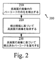
図2は本発明のいくつかの実施形態に係る方法200の例を示すフローチャートである。ステップ210において、バーコードが低画質の画像の中に存在しているかどうかかが検出される。ステップ220において、バーコードが検出されると、より高画質の画像が取得される。ステップ230において、より高画質の画像を用いて検出済みバーコードの復号化が行われる。
FIG. 2 is a flowchart illustrating an example of a
図3は本発明のいくつかの実施形態に係る方法300の例を示すフローチャートである。ステップ310において、バーコードが低画質の画像内に存在するか否かが検出される。上述のようにこの検出ステップはおそらくユーザからのインタラクションなしで連続的に実行しているものである(ステップ310:NO)。
FIG. 3 is a flowchart illustrating an example of a
バーコードが検出されれば(ステップ310:YES)、処理はオプションのステップ315へ進み、当該ステップにおいて、バーコードが検出されたことをユーザに通知し、バーコード情報の読み出しが望ましいかをユーザに尋ねるユーザアラートが発せられる。ユーザがバーコード情報の読み出しを望まなければ(ステップ315:NO)、処理はステップ310へ戻る。しかし、ユーザがバーコード情報の読み出しを望めば(ステップ315:YES)、処理はステップ320へ進む。
If a bar code is detected (step 310: YES), the process proceeds to
ステップ320において、より高画質の画像が取得され、次いで、処理はステップ330へ進む。ステップ330において、上記より高画質の画像を用いて検出済みのバーコードの復号化が行われ、次いで、処理はオプションのステップ335へ進む。このステップでユーザはバーコードの復号化に成功した旨の通知を受け、次いで、おそらくバーコード情報が与えられる。
In step 320, a higher quality image is acquired, and then processing proceeds to step 330. In
たとえこのような画像がバーコードの復号化に用いるには十分に高い画質のものではない場合であっても、本発明の実施形態を用いて低画質の画像に対するロバストな検出アルゴリズムの適用が可能である。 Even if such an image is not of a quality high enough to be used for barcode decoding, a robust detection algorithm can be applied to a low quality image using embodiments of the present invention. It is.
このようなロバストな検出アルゴリズムの一例として、画像内の矩形領域をサーチする検出アルゴリズムがある。このような検出アルゴリズムは、(バーコード復号化アルゴリズムなどの)バーコード読み取り用ソフトウェアに比べ、よりロバストになるように設計され得る。例えば、QRコードは必ず矩形であるため、バーコードの検出を可能にするには、低画質の画像内の矩形構造を探すことで十分である場合もある。このような構造が発見された場合、以上説明したようにより高画質の画像が取得され、(検出時のものとは別のアルゴリズムを用いて)復号化が行われる。
いくつかの実施形態では、検出ステップはバーコードに関連づけられたヒストグラムから特徴抽出を行うステップを有するものであってもよい。QRコードの「位置検出パターン(finding pattern)」などを探す代わりに、コード全体が考慮される。これらの実施形態のなかには、検出ステップ時にサポート・ベクトル・マシン(support vector machine)を利用できるものもある。
An example of such a robust detection algorithm is a detection algorithm that searches for a rectangular area in an image. Such a detection algorithm can be designed to be more robust than bar code reading software (such as a bar code decoding algorithm). For example, since a QR code is always rectangular, it may be sufficient to look for a rectangular structure in a low-quality image to enable bar code detection. When such a structure is found, a high-quality image is acquired as described above, and decoding is performed (using an algorithm different from that at the time of detection).
In some embodiments, the detecting step may include performing feature extraction from a histogram associated with the barcode. Instead of looking for a “finding pattern” or the like of the QR code, the entire code is considered. In some of these embodiments, a support vector machine can be utilized during the detection step.
QRコードの画像は、識別用YUVヒストグラム(輝度(luma)及び色度(chrominance)のヒストグラム)を生成できる。これらのヒストグラムから得られる属性をバーコードの存否を検出するための特徴として利用してもよい。いくつかの実施形態では、これらのヒストグラムが評価され、もし平均輝度(Y−成分)がスペクトルの中心にあれば(これは輝度分散が大きく、かつ、不十分に表示されていたり、過剰に表示されていたりするカラーが存在しないことを意味する)、当該画像が例えばQRコードを示すものであるという判定を行うことが可能となる。 The QR code image can generate an identification YUV histogram (brightness (luma) and chrominance histogram). Attributes obtained from these histograms may be used as features for detecting the presence or absence of barcodes. In some embodiments, these histograms are evaluated and if the average luminance (Y-component) is in the center of the spectrum (this is a high luminance variance and is poorly displayed or overdisplayed) This means that there is no color that is displayed), and it is possible to determine that the image shows, for example, a QR code.
ヒストグラムはピクセル位置に関する情報を含まないことを付記しておく。したがって、実施形態によっては画像上にわたってスライドさせるウィンドウを用いるものもある。その場合、実施形態によっては、SVM(support vector machine)を用いて、ウィンドウがバーコード上にわたって配置されているかどうかをウィンドウの個々の位置について評価するものもある。実施形態によっては、画像領域がピクセルで充たされていれば、バーコードである可能性のあるバーコードピクセルとしてSVMによって注目されるバーコードが存在していると判定するものもある。 Note that the histogram does not contain information about pixel locations. Therefore, some embodiments use a window that slides over the image. In that case, in some embodiments, a support vector machine (SVM) is used to evaluate whether the window is placed over a barcode for each position of the window. In some embodiments, if the image area is filled with pixels, it is determined that there is a barcode noticed by the SVM as a barcode pixel that may be a barcode.
本発明の実施形態のなかには、(バーコードである可能性のあるバーコードピクセルであるか、ないかのいずれかのピクセルを含む)、結果として得られる2値画像をさらに処理するものもある。例えば、2値画像は収縮フィルタにより処理できると共に、最小のサイズ条件を適用して実際のバーコードの分離を行うことが可能である。 Some embodiments of the present invention (including any pixel that may or may not be a barcode) further process the resulting binary image. For example, a binary image can be processed by a shrink filter, and an actual barcode can be separated by applying a minimum size condition.
図4は本発明のいくつかの実施形態に係る例示の方法400を示すフローチャートである。例えば、方法400は図2及び図3の方法ステップ210又は310の一部としてそれぞれ実行されてもよい。
FIG. 4 is a flowchart illustrating an
ステップ410において、ウィンドウは解析されるために画像上にわたってスライドされる。画像全体にわたって、又は、画像の一部のみにわたってウィンドウをスライドさせることができる。ステップ420において、ウィンドウ位置の個々の位置又はウィンドウ位置のいくつかの位置に対してYUVヒストグラムが生成される。次いで、ステップ430において、YUVヒストグラムが生成されるウィンドウ位置の個々の位置又はウィンドウ位置のいくつかの位置について、このウィンドウ位置がバーコードである可能性のあるバーコードピクセル(いくつかの実施形態では1グループのバーコードピクセル)を表しているかどうかの評価が行われる。
In
ステップ410、420及び430のうちの2以上のステップを反復して実行したり(1つのウィンドウ位置のすべてについて上記ステップを実行し、次いで次のウィンドウ位置のすべてについて実行するなど)、あるいは、順番に実行したり(まず、すべてのウィンドウ位置についてステップ410を実行し、次いで、ステップ420を実行するなど)することが可能であることに留意されたい。
Repeat two or more of
図5は本発明のいくつかの実施形態を用いることによって得られた結果を明示する図である。左画像は原画像を示し、右画像は、ウィンドウを画像上にわたってスライドさせ、次いで、YUVヒストグラムが生成され、評価された後で結果として得られる2値画像を示す。 FIG. 5 illustrates the results obtained by using some embodiments of the present invention. The left image shows the original image and the right image shows the resulting binary image after the window is slid over the image and then a YUV histogram is generated and evaluated.
いくつかの実施形態では、図4と関連して説明した例示のアルゴリズムは、実質的に黒と白との間で変動する領域の発見を目的とするものである。代替のアプローチは画像内に大きな勾配を探すためのアプローチであってもよい。 In some embodiments, the exemplary algorithm described in connection with FIG. 4 is intended to find regions that vary substantially between black and white. An alternative approach may be an approach to look for large gradients in the image.
この代替アプローチを採用する実施形態のなかには、コード構造の特徴に注目して、コード内のピクセル間の強度のコントラストを調査するものもある。大きく変動する強度が、バーコードの存在を示すと考えられる大きな勾配振幅を暗示している場合がある。これらの実施形態のなかには勾配フィルタ(gradient filter)及びクロージングフィルタ(closing filter)を利用するものもある。 Some embodiments that employ this alternative approach look at the characteristics of the code structure and investigate the intensity contrast between the pixels in the code. Largely varying intensities may imply a large gradient amplitude that is believed to indicate the presence of a barcode. Some of these embodiments utilize a gradient filter and a closing filter.
バーコード領域はピクセル相互間に大きな強度差を持つピクセルを中に含み、この強度差が大きな勾配を結果としてもたらすことになる。したがって、いくつかの実施形態によれば、大きな勾配振幅を持つ多くのピクセルを有する領域は、該領域がQRコードのようなバーコードであることを暗示していると想定される。QRコードの例を用いれば、このようなバーコードがすべての方向に勾配を有していることにも気がつく。実施形態のなかにはこの属性を利用するものもある。勾配属性を利用する実施形態のなかには、可能性のあるバーコードの位置とサイズとを表示する高速法の提供を目的とするものもある。いくつかの実施形態によれば、正しいバーコードである通知を誤報(false alarm)から識別するさらに複雑な方法でこの表示を利用することが可能である。したがって、勾配属性を利用する実施形態のなかには、誤ったバーコードの発生確率が低いため、さらに複雑な後続する方法にこの誤ったバーコードの処理を任せて、いずれの表示が実際に真のバーコードであるかを判定させるようにする方法の提供を目的とするものもある。 The barcode region contains pixels with large intensity differences between the pixels, and this intensity difference results in a large gradient. Thus, according to some embodiments, a region having many pixels with large gradient amplitude is assumed to imply that the region is a barcode, such as a QR code. Using the QR code example, you will also notice that such a barcode has a gradient in all directions. Some embodiments use this attribute. Some embodiments that use gradient attributes are intended to provide a fast method for displaying the location and size of possible barcodes. According to some embodiments, this indication can be used in a more complex way to identify notifications that are correct barcodes from false alarms. Therefore, in some embodiments that use gradient attributes, the probability of false barcodes is low, so that the processing of the false barcodes can be left to a more complicated subsequent method, and any display is actually a true barcode. Some of them aim to provide a method for determining whether a code is used.
実施形態のなかには、4つの異なる方向に4つの勾配フィルタを適用し、次いで、その結果を組み合わせることによってバーコードから環境を分離する処理に注目するものもある。4つの異なる方向にソーベル勾配フィルタ(Sobel gradient filter)を適用し、かつ、4つの勾配画像を形成するアルゴリズムの提供も可能である。これらの画像は閾値を用いて2値画像に変えることができる。これらの2値画像はクロージングフィルタを用いて処理され、次いで、該2値画像を組み合わせて、例えば、論理AND演算を用いて結果画像に変えることが可能である。実施形態のなかには、この結果生じる画像内のすべての閉領域をバーコードと規定するものもある。いくつかの実施形態では、閉領域をバーコードと規定するためには、閉領域は所定の閾値よりも広いものでなければならない。 Some embodiments focus on the process of separating the environment from the barcode by applying four gradient filters in four different directions and then combining the results. It is also possible to provide an algorithm that applies a Sobel gradient filter in four different directions and forms four gradient images. These images can be converted into binary images using a threshold. These binary images can be processed using a closing filter, and the binary images can then be combined and converted into a result image using, for example, a logical AND operation. In some embodiments, the resulting closed region in the image is defined as a barcode. In some embodiments, in order to define a closed region as a barcode, the closed region must be wider than a predetermined threshold.
図6は、他の画像データが大きな勾配を生みだしそうにないのに対して、QRコードがすべての4つの方向に大きな勾配を生みだすものであることを明示する図である。図6において、(a)は原画像であり、(b)、(c)、(d)及び(e)は4つの異なる方向に対応する勾配画像を明示し、さらに、(f)は(b)、(c)、(d)及び(e)の間で論理AND演算を実行した後の結果を明示する図である。 FIG. 6 is a diagram demonstrating that the QR code produces a large gradient in all four directions, whereas other image data is unlikely to produce a large gradient. In FIG. 6, (a) is an original image, (b), (c), (d) and (e) clearly show gradient images corresponding to four different directions, and (f) is (b) ), (C), (d) and (e) are diagrams clearly showing the result after performing a logical AND operation.
勾配調査実施形態に係るアルゴリズムはバーコード位置だけでなく、ほぼ正確なバーコードサイズも提示することができる。これらの実施形態のうちのいくつかの実施形態の利点として、アルゴリズムが1つの閾値や、きわめて機密を要するソリューション(正しい閾値の発見が困難であり、かつ、アルゴリズムのトレーニングに用いられるデータセットに閾値が密接に関連づけられていることなど)に依存せず、代わりに、多くの閾値に依存するという点が挙げられる。このため、アルゴリズムがさらに安定したものになると共に、ロバストなものになる。 The algorithm according to the gradient survey embodiment can present not only the barcode position, but also an almost accurate barcode size. The advantage of some of these embodiments is that the algorithm has a single threshold or a highly sensitive solution (it is difficult to find the correct threshold and the data set used to train the algorithm has a threshold Is closely related), and instead depends on many thresholds. This makes the algorithm more stable and robust.
勾配評価実施形態のうちのいくつかの実施形態の他の利点として、ライン及び他の先鋭な境界ライン(これらのラインを単一の勾配画像に分離することは困難であると考えられる)が結果として生じる合成画像の中に消える可能性があり、したがって、勾配閾値を低い値にセットできると共に、この閾値が、該閾値の同調時にエラーに対してかなり鈍感になるという点が挙げられる。 Another advantage of some of the gradient evaluation embodiments is that lines and other sharp boundary lines (which would be difficult to separate these lines into a single gradient image) result. The gradient threshold can be set to a low value, and this threshold can be quite insensitive to errors when the threshold is tuned.
勾配画像を評価する際に、いくつかの例示のQRコードのなかには、バーコードピクセルのすべてが必ずしも大きな勾配振幅を取得するわけではないものもあることは明らかである。すべてのコードピクセルが閾値以上に符号化される確率が高くなるように勾配閾値を下げる代わりに、実施形態によっては、クロージングフィルタを個々の勾配画像に適用することによって個々の勾配画像を処理するものもある。クロージングフィルタを設計して、バーコード内のギャップを埋めるようにすることも可能であり、さらに、フィルタ設計はクワイエットゾーンの幅を考慮してもよい。いくつかの実施形態では、4つの異なるクロージングフィルタ(個々の勾配画像について1つのクロージングフィルタ)が用いられる。実施形態のなかには垂直方向の場合よりも水平方向の場合に水平勾配をより高く評価する勾配画像を閉じるものもある。したがって、水平方向のクワイエットゾーンは手つかずのままとなる。その他の勾配画像を組み合わせる前に、その他の勾配画像に対して同様のクロージング処理を行うようにしてもよい。 When evaluating gradient images, it is clear that some exemplary QR codes may not all of the barcode pixels necessarily obtain large gradient amplitudes. Instead of lowering the gradient threshold so that the probability that all code pixels are encoded above the threshold is increased, in some embodiments, each gradient image is processed by applying a closing filter to the individual gradient image. There is also. It is also possible to design a closing filter to fill the gaps in the barcode, and the filter design may take into account the width of the quiet zone. In some embodiments, four different closing filters (one closing filter for each gradient image) are used. Some embodiments close a gradient image that evaluates the horizontal gradient higher in the horizontal direction than in the vertical direction. Therefore, the horizontal quiet zone remains untouched. Before the other gradient images are combined, the same closing process may be performed on the other gradient images.
このアプローチの利点のいくつかとして、クワイエットゾーンが損なわれずに保持される確率がさらに高くなるという点、及び、普通の矩形又は正方形の形状のクロージングフィルタの場合に比べてより低い精度で勾配閾値をセットできるという点が挙げられる。 Some of the advantages of this approach are that the quiet zone is more likely to be preserved intact, and the gradient threshold is set with less accuracy than in the case of a regular rectangular or square shaped closing filter. The point is that it can be set.
勾配評価実施形態のうちのいくつかのために利用されるアルゴリズムはフィルタに基づくものとなる。時間のかかる計算がないためこのアルゴリズムは高速なものになる。 The algorithm used for some of the gradient evaluation embodiments will be filter based. This algorithm is fast because there is no time consuming calculation.
バーコードの位置を発見するために、以上説明したような勾配評価実施形態を単独で用いてもよい。上記とは別に、これらのアルゴリズムから得られる出力をバーコードの検出時に第1のステップとして閲覧することができる。目的がミスの確率を低減させることであった勾配評価の実施形態のうちのいくつかにおいて、出力結果は多量の誤報を避けるようにさらに評価されるかもしれない。 In order to find the position of the barcode, the gradient evaluation embodiment as described above may be used alone. Apart from the above, the output obtained from these algorithms can be viewed as a first step when a barcode is detected. In some of the gradient evaluation embodiments where the goal was to reduce the probability of misses, the output result may be further evaluated to avoid a large amount of false alarms.
以下、勾配法によって発見されたバーコード候補が実際にバーコードであるかどうかの検証を目的とする実施形態について説明する。したがって、出力は、勾配法によって画定された領域の承認又は拒絶であってもよい。 Hereinafter, an embodiment for verifying whether a barcode candidate discovered by the gradient method is actually a barcode will be described. Thus, the output may be an approval or rejection of the area defined by the gradient method.
実施形態のなかには(正方形などの)画像の形状を利用して主要属性として画像からバーコードの抽出を行うものもある。実施形態のなかには、収縮フィルタ、ケニーのエッジ検出アルゴリズム(Canny edge detector)、ハフ変換及びいくつかの基礎的な代数学を用いるものもある。 In some embodiments, a barcode is extracted from an image as a main attribute using the shape of the image (such as a square). Some embodiments use a shrink filter, a Kenny edge detector, a Hough transform, and some basic algebra.
いくつかの実施形態によれば、勾配法から返された位置を中心とするサブ画像が、勾配法によって判定されたサイズとほぼ同じサイズを持つ正方形である場合、当該領域がバーコードとして分類されるように、勾配法によって画定された領域はさらに評価される。この評価はハフ変換を採用して行ってもよい。 According to some embodiments, if the sub-image centered on the position returned from the gradient method is a square having approximately the same size as determined by the gradient method, the region is classified as a barcode. As such, the region defined by the gradient method is further evaluated. This evaluation may be performed by employing Hough transform.
ハフ変換の計算上の複雑さは、要求される高い検出精度及び検出範囲のサイズと共に増大する。したがって、バーコードのサイズと位置とに関して勾配法から得られる情報を利用することによる範囲の限定によって計算上の複雑さが低減されることになる。 The computational complexity of the Hough transform increases with the required high detection accuracy and detection range size. Thus, computational complexity is reduced by limiting the range by utilizing information obtained from the gradient method with respect to the size and position of the barcode.
いくつかの実施形態では、本方法は3つの部分、すなわち(バーコードのコントラストが強められる)前処理と、正方形の発見処理と、正方形の検証処理とに分割される。正方形検証処理によって検出エラーを減らすことが可能となる。勾配法と組み合わされて、この方法は低いミス発生確率を保持すると共に、さらに、低い誤報の発生確率を得ることを目的とすることができる。 In some embodiments, the method is divided into three parts: preprocessing (in which the barcode contrast is enhanced), square discovery processing, and square verification processing. Detection errors can be reduced by the square verification process. Combined with the gradient method, this method can be aimed at retaining a low probability of miss occurrence and, furthermore, obtaining a low probability of false alarm occurrence.
前処理及びエッジ抽出ステップと関連して、 例えば、QRコードの正方形検出を首尾よく行うために、クワイエットゾーンと実際のバーコードとの間に良好なコントラスを設けることが重要になる場合がある。エッジ検出が直接利用されれば、バーコードに関係する正方形を正しく閉じることができなくなるリスクが生じると共に、バーコード正方形の内部に多くのエッジが発見されることになるリスクも生じることになる。黒と白のピクセルの分散セットを有するというバーコードの特徴を利用して、実施形態によっては、コードの内部にあるエッジを避けるために、エッジ検出の適用前に収縮フィルタを使用するものもある。 In connection with the pre-processing and edge extraction steps, it may be important to provide a good contrast between the quiet zone and the actual barcode, for example, for successful QR code square detection. If edge detection is used directly, there is a risk that the squares associated with the barcode will not be properly closed, and there will be a risk that many edges will be found inside the barcode square. Utilizing the bar code feature of having a distributed set of black and white pixels, some embodiments use a shrink filter before applying edge detection to avoid edges that are inside the code. .
図7はこのような実施形態の例示の結果を明示する図である。左画像は原画像であり、中間画像は収縮フィルタの結果を示す像であり、右画像はエッジ検出アルゴリズム(ケニーのエッジ検出アルゴリズム)を収縮フィルタ済みの画像に適用した結果を示す画像である。収縮フィルタはクワイエットゾーンの幅を考慮するように設計することができる。 FIG. 7 illustrates the exemplary results of such an embodiment. The left image is an original image, the intermediate image is an image showing the result of the contraction filter, and the right image is an image showing the result of applying the edge detection algorithm (Kenny's edge detection algorithm) to the image after the contraction filter. The shrink filter can be designed to take into account the width of the quiet zone.
画像の前処理を施した後、正方形サーチを実行することができる。いくつかの実施形態では、C.R.Jung及びR.Schrammの「ウィンドウ化されたハフ変換に基づく矩形検出」(コンピュータグラフィックと画像処理に関するブラジルシンポジウム、2004年)において提案されているような画像から正方形の抽出を行う方法を正方形発見ステップにおいて用いてもよい。エッジ画像内の個々のピクセルに対して、或る一定の近傍をカバーするサブウィンドウが適用され、ラインに対するハフ変換がサブウィンドウに対して計算される。ハフ変換画像を分析することによって、正方形(又は矩形)の発見が可能となる。いくつかの実施形態によれば、(勾配法から得られる出力に基づいて)バーコードが位置していると予想される画像部分に対してのみハフ変換が適用されなければならない。閾値を越えるハフ画像内のピーク数が適度に少なければ、すべてのピークが他のピークに対して、対象関係を考慮せずに検査される全サーチとして正方形サーチを実行することが可能となる。対称関係が考慮されない場合、正方形サーチは、個々のピクセルに対して1つのハフ画像内で行われるのではなく、前処理済みの画像全体に対して1つのハフ画像内でサーチを実行することが可能となり、計算上の複雑さを減らすことが可能となる。 After image preprocessing, a square search can be performed. In some embodiments, C.I. R. Jung and R.A. A method of extracting a square from an image as proposed in Scramm's "Rectangle detection based on windowed Hough transform" (Brazil symposium on computer graphics and image processing, 2004) may be used in the square finding step. Good. For each pixel in the edge image, a subwindow covering a certain neighborhood is applied and a Hough transform for the line is calculated for the subwindow. By analyzing the Hough transform image, a square (or rectangle) can be found. According to some embodiments, the Hough transform must be applied only to the portion of the image where the barcode is expected to be located (based on the output obtained from the gradient method). If the number of peaks in the Hough image that exceeds the threshold is moderately small, it is possible to execute a square search as a full search in which all peaks are inspected with respect to other peaks without considering the object relationship. If a symmetry relationship is not considered, a square search may be performed within a single Hough image for the entire preprocessed image, rather than being performed within a single Hough image for individual pixels. And it is possible to reduce the computational complexity.
ハフ空間において正方形が発見されると、本発明のいくつかの実施形態に基づいて、正方形の有効性の検証が可能となる。この正方形の検証は2値エッジ画像に対して実行することができる。正方形の検証は誤報の数がさらに減少するという結果をもたらすことができる。ハフ画像内で発見された正方形のすべての辺を2値エッジ画像内において検証できれば、正方形はいくつかの実施形態に基づいて承認を受けることができる。 Once a square is found in the Hough space, the validity of the square can be verified according to some embodiments of the present invention. This square verification can be performed on binary edge images. Square verification can result in a further reduction in the number of false alarms. If all sides of a square found in the Hough image can be verified in the binary edge image, the square can be approved based on some embodiments.
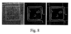
図8はエッジ抽出及び例示の画像に対応する正方形の発見を明示する図である。左の画像は原画像であり、中央の画像はエッジ抽出の結果を示す画像である。右の画像はエッジ抽出の結果に対してオーバーレイされたハフ変換を通じて発見された正方形を示す。 FIG. 8 is a diagram demonstrating edge extraction and finding a square corresponding to the exemplary image. The left image is an original image, and the center image is an image showing the result of edge extraction. The right image shows a square found through the Hough transform overlaid on the edge extraction results.
図9は本発明のいくつかの実施形態に基づく方法900を示すフローチャートである。例えば、方法900は図2及び図3の方法ステップ210又は310の一部としてそれぞれ実行することができる。
FIG. 9 is a flowchart illustrating a
ステップ910において、(おそらくいくつかの方向で)1以上の勾配フィルタが画像に対して適用され、次いで、ステップ920においてクロージングフィルタがステップ910の結果に対して適用される。サブステップ921と922によって例示されているように、クロージングフィルタは膨張フィルタ(dilation filter)と収縮フィルタとを備えてもよい。
In
ステップ930において、ステップ920の結果生じる画像内に閉領域が発見される。このステップは上記記載のようなフィルタ済みの画像に対する論理AND演算の適用を含んでもよい。オプションのステップ935において、閾値よりも小さなすべての発見済み閉領域を取り除くことができる。次いで、残りの閉領域の各閉領域の重心及び辺の長さがステップ940と950においてそれぞれ計算される。例えば、辺の長さは領域内の画素数の平方根として計算することができる。
In
ステップ910〜950は以前に詳述したような勾配法を表す。本方法はステップ950において終了することができ、その結果は、図2及び図3のステップ220又は320のそれぞれの実行時に利用され得る。いくつかの実施形態では、ステップ950もオプションである。辺の長さが計算されない場合、例えば、所定のサイズの、かつ、重心に集められた画像領域全体又はサブ画像領域をステップ220又は320の実行時に用いることができる。
Steps 910-950 represent a gradient method as detailed previously. The method may end at
上記とは別に、本方法はステップ960へ進み、そこで、ステップ940と950において発見された情報に基づいて1以上のサブ画像が原画像から抽出される。
Alternatively, the method proceeds to step 960 where one or more sub-images are extracted from the original image based on the information found in
次いで、ステップ970において、サブ画像内に含まれているエッジを検出するためにサブ画像の各々が前処理される。この前処理は、サブステップ971及び972によって例示のように、収縮フィルタ及び(ケニーのエッジ検出アルゴリズムのような)エッジ検出アルゴリズムの適用ステップを有してもよい。処理はステップ980へ続き、そこで、ステップ970から出力された、結果のサブ画像において正方形が発見される。正方形発見ステップは、サブステップ981及び982によって例示されているように、正方形を抽出するためのハフ変換適用ステップ及び結果分析ステップを含むことができる。
Next, in
本方法はステップ980において終了することができ、その結果は図2及び図3のステップ220又は320のそれぞれが実行される際に利用され得る。上記とは別に、本方法はステップ990へ進み、そこで、ステップ980において発見された正方形は、ステップ970において発見されたエッジを用いて検証される。発見された正方形が、十分な程度の対応するエッジを有している旨の判定が行われた場合、この発見された正方形は拒絶され得る。
The method may end at
ステップ960〜990は以前に詳述したような正方形発見法を表す。 Steps 960-990 represent a square finding method as detailed previously.
バーコード候補を特定するステップにおいて(勾配法のような)単純なフィルタを用いた方法を利用し、次いで、正方形発見法を用いて特定済みの領域を認証することによって、高速かつ正確なバーコード検出結果を得ることができる本発明の実施形態について説明してきた。 A fast and accurate barcode by using a simple filter-based method (such as a gradient method) in the step of identifying barcode candidates and then authenticating the identified region using square discovery Embodiments of the present invention that can obtain detection results have been described.
最適なパラメータ設定は、アプリケーションに応じて変動し得るものであり、かつ、例えば、データとシミュレーションのトレーニングを通じて発見され得るものである。さらに、ミス及び誤報それぞれの発生確率に対する要件に応じて様々なパラメータ設定値の適用が可能となる。 Optimal parameter settings can vary depending on the application and can be found, for example, through data and simulation training. Furthermore, various parameter setting values can be applied according to the requirements for the occurrence probability of each error and false alarm.
本発明の実施形態の例示のフィルタ及び検出ステップでの使用に適した他のツールに関するさらなる詳細については、Jonas Alfthanの「ぼやけ画像内の2次元バーコードのロバストな検出」(ストックホルム大学、数値分析及びコンピュータ科学学部修士論文、2008年3月、並びに該論文の参考文献)に記載がある。 For further details on exemplary filters and other tools suitable for use in the detection step of embodiments of the present invention, see "Joson Alfthan's" Robust detection of two-dimensional barcodes in blurred images "(University of Stockholm, Numerical Analysis). And a master's thesis in the Faculty of Computer Science, March 2008, and references of the paper).
図10は本発明の実施形態に係る装置を備えた例示の移動端末1010を示す。移動端末1010は無線リンクを介して基地局サイトに接続されてもよい。 FIG. 10 shows an exemplary mobile terminal 1010 equipped with an apparatus according to an embodiment of the present invention. The mobile terminal 1010 may be connected to the base station site via a radio link.
移動端末1010は概略正面図に移動電話機として例示されている。この例示の移動端末1010は装置の筐体に取り付けられたアンテナ1011を備えている。上記とは別に、移動端末1010は装置の筐体内部に取り付けられた内部アンテナを有してもよい。移動端末1010は複数のアンテナさえ備えてもよい。移動端末1010は、ディスプレイ、キーパッド、スピーカ及びマイクをさらに備えてもよい。これらは一体として、移動端末1010を動作させるためのマン・マシン・インタフェースを提供するものである。移動端末はカメラのような画像取得装置1012をさらに備えている。
The
例示の移動端末1010は、無線基地局への無線リンクを介して移動通信ネットワークと接続するように適合させることができる。したがって、移動端末1010のユーザは、音声電話、データ呼、テレビ電話及びファックス送信のような従来の回線交換型通信サービス、及び、電子メッセージ交換、VoIP、インターネットの閲覧、電子商取引などのようなパケットベースのサービス、のうちの少なくともいずれかのサービスを利用することが可能となる。この目的のために、移動端末1010及び基地局は、例えばUMTS(汎用移動体通信システム)又はUMTS LTE(UMTSロングタームエボリューション)などの少なくとも1つの移動通信規格に準拠することができる。移動通信ネットワークとの接続は、復号化済みのバーコード情報を利用して、移動通信ネットワークを介してアクセス可能なインターネットサーバ上で(製品やイベントなどの)さらに別の情報を検索する可能性を提供することができる。
The example mobile terminal 1010 can be adapted to connect to a mobile communication network via a radio link to a radio base station. Thus, the user of the mobile terminal 1010 can use conventional circuit-switched communication services such as voice calls, data calls, videophone calls and fax transmissions, and packets such as electronic message exchange, VoIP, Internet browsing, electronic commerce, etc. It becomes possible to use at least one of the base services. For this purpose, the
以上説明した本発明の実施形態及びその均等物は、ソフトウェア又はハードウェアの形で、あるいはこれらを組み合わせた形で実現することができる。これらの実施形態及びその均等物はデジタル信号プロセッサ(DSP)、中央演算処理装置(CPU)、コプロセサユニットのような通信装置に関連づけられた、あるいは、通信装置に不可欠な汎用回路によって、又は、例えば特定用途向け集積回路(ASIC)のような専用回路によって実行されてもよい。このようなすべての形態が本発明の範囲に含まれるものとして想定されている。 The above-described embodiments of the present invention and equivalents thereof can be realized in the form of software or hardware, or a combination thereof. These embodiments and their equivalents may be associated with a communication device such as a digital signal processor (DSP), a central processing unit (CPU), a coprocessor unit, or by a general purpose circuit essential to the communication device, or For example, it may be performed by a dedicated circuit such as an application specific integrated circuit (ASIC). All such forms are envisioned as being within the scope of the present invention.
本発明は、回路/ロジック回路を備えた電子装置、若しくは、本発明の実施形態のうちの任意の実施形態に係る方法を実行する電子装置の内部において実施され得る。上記電子装置は、例えば、携帯用又はハンドヘルド型移動無線通信装置、移動無線端末、移動電話機、コミュニケータ、電子手帳、スマートフォン、デジタルカメラ、バーコードスキャナ、コンピュータ、移動体ゲーム装置、又は(腕)時計などであってもよい。 The present invention may be implemented within an electronic device comprising a circuit / logic circuit or an electronic device that performs a method according to any of the embodiments of the present invention. The electronic device is, for example, a portable or handheld mobile wireless communication device, a mobile wireless terminal, a mobile phone, a communicator, an electronic notebook, a smartphone, a digital camera, a barcode scanner, a computer, a mobile game device, or (arm) It may be a clock.
本発明のいくつかの実施形態によれば、コンピュータプログラム製品には、例えば、ディスケットやCD−ROMなどのようなコンピュータ可読媒体が含まれる。コンピュータ可読媒体は、プログラム命令を含むコンピュータプログラムが保存されているものであってもよい。コンピュータプログラムは、例えば移動端末の中に含まれ得るデータ処理ユニットへロード可能なものであってもよい。データ処理ユニットへロードされると、コンピュータプログラムは、データ処理ユニットに関連づけられた、又は、データ処理ユニットに不可欠のメモリに保存され得る。いくつかの実施形態によれば、コンピュータプログラムは、データ処理ユニットへロードされ、かつ、データ処理ユニットによって実行されると、例えば、図2〜図4又は図9に図示の方法に基づいて方法ステップをデータ処理ユニットに実行させることができる。 According to some embodiments of the present invention, the computer program product includes a computer readable medium such as, for example, a diskette or CD-ROM. The computer readable medium may store a computer program including program instructions. The computer program may be loadable into a data processing unit that may be included in the mobile terminal, for example. Once loaded into the data processing unit, the computer program can be stored in a memory associated with or integral to the data processing unit. According to some embodiments, the computer program is loaded into the data processing unit and executed by the data processing unit, for example, based on the method steps illustrated in FIGS. Can be executed by the data processing unit.
種々の実施形態に関して本書面に本発明を記載した。しかし、当業者であれば、本発明の範囲にやはり属することになる上記記載の実施形態の非常に多くの変形例を認識するであろう。例えば、本書面に記載の方法実施形態は、或る一定の順序で実行される方法ステップによって行われる例示の方法について記載するものである。しかし、これら一連のイベントは、本発明の範囲から逸脱することなく、別の順序で起こり得るものであることが認識される。さらに、方法ステップによっては、たとえ順番に実行されるものとして記載されたものであっても、同時に実行され得るものもある。 The invention has been described herein with reference to various embodiments. However, those skilled in the art will recognize numerous variations of the above-described embodiments that still belong to the scope of the invention. For example, the method embodiments described herein describe an exemplary method performed by method steps performed in a certain order. However, it will be appreciated that these series of events may occur in a different order without departing from the scope of the present invention. Furthermore, some method steps may be executed simultaneously, even if they are described as being executed in sequence.
同様に、ここで注目すべき点として、本発明の実施形態についての記述の中で、機能ブロックの、特別のユニットへの分割が決して本発明に限定されるものではないという点が挙げられる。反対に、これらの分割は単に例示にすぎない。1つのユニットとして本明細書に記載の機能ブロックを2以上のユニットに分割してもよい。同様に、2以上のユニットとして実装されている本明細書に記載の機能ブロックを、本発明の範囲から逸脱することなく単一ユニットとして実装してもよい。 Similarly, it should be noted that in the description of the embodiments of the present invention, the division of functional blocks into special units is by no means limited to the present invention. Conversely, these divisions are merely exemplary. The functional block described in this specification may be divided into two or more units as one unit. Similarly, functional blocks described herein that are implemented as two or more units may be implemented as a single unit without departing from the scope of the invention.
したがって、上記記載の実施形態の限定は、単に例示を目的とするものにすぎず、決して限定を目的とするものではないことは明らかである。代わりに、本発明は添付の特許請求の範囲並びにすべての妥当なその均等物によって限定されるものと解される。 Thus, it should be apparent that the above-described embodiments are for illustrative purposes only and are not intended to be limiting in any way. Instead, the invention is construed as limited by the appended claims and all reasonable equivalents thereof.
Claims (27)
画像取得装置によって取得された第1の画像であって、第1の画質を有し、第1の領域を撮像した第1の画像に、前記バーコードが存在するか否かを検出する工程(210、310)であって、継続して繰り返し実行される検出する工程と、
前記バーコードが存在することが検出された場合、第2の画質を有し、第2の領域を捉えた第2の画像であって、前記第2の画質は前記第1の画質より高く、前記第2の領域が少なくとも前記第1の領域と部分的に重なる第2の画像を、前記画像取得装置によって取得する工程(220、320)と、
前記情報を読み出すために、前記第2の画像に基づいて前記バーコードを復号する工程(230、330)と、を備え、
前記検出する工程が、
第1のウィンドウサイズであって、前記第1の領域より小さいサイズの第1のウィンドウサイズを有するウィンドウを、前記第1の画像上でスライドする工程(410)と、
1以上のウィンドウ位置について、YUVヒストグラム(輝度及び色度のヒストグラム)を生成する工程(420)と、
1以上のウィンドウ位置について、前記ウィンドウ位置にバーコードが存在するかどうかを判定するために、対応する前記YUVヒストグラムを評価する工程(430)と、を備えることを特徴とする方法。 A method for reading information included in a barcode,
A step of detecting whether or not the barcode is present in the first image acquired by the image acquisition device and having the first image quality and capturing the first region ( 210, 310), which is continuously and repeatedly executed, and
If it is detected that the barcode is present, the second image having a second image quality and capturing a second region, wherein the second image quality is higher than the first image quality; Acquiring (220, 320) by the image acquisition device a second image in which the second region at least partially overlaps the first region;
To read the information, comprising a step (230, 330) for decoding the bar code based on the second image,
The step of detecting comprises
Sliding a window having a first window size having a first window size smaller than the first region on the first image (410);
Generating (420) a YUV histogram (brightness and chromaticity histogram) for one or more window positions;
For one or more window position, in order to determine whether a bar code is present in the window position, and wherein the Rukoto includes a step of evaluating the YUV histograms corresponding (430), the.
前記バーコードが復号されるとユーザアラートを生成する工程をさらに備えることを特徴とする請求項11に記載の方法。 The detecting step, the obtaining step, and the decoding step are performed without user operation,
The method of claim 11, further comprising generating a user alert when the barcode is decoded.
勾配フィルタが適用された1以上の信号を生成するために、1以上の勾配フィルタを前記第1の画像に対して適用する工程(910)と、
膨張フィルタが適用された1以上の信号を生成するために、1以上の膨張フィルタを前記勾配フィルタが適用された1以上の信号に対して適用する工程(921)と、
収縮フィルタが適用された1以上の信号を生成するために、1以上の収縮フィルタを前記膨張フィルタが適用された1以上の信号に対して適用する工程(922)と、
前記収縮フィルタが適用された1以上の信号において閉領域を探す工程と、
少なくとも1つの閉領域について、対応する重心座標を算出する工程と、を備えることを特徴とする請求項1乃至15のいずれか1項に記載の方法。 The first image is represented by a first signal, and the detecting step comprises
Applying one or more gradient filters to the first image to generate one or more signals to which a gradient filter has been applied (910);
Applying one or more expansion filters to one or more signals to which the gradient filter has been applied to generate one or more signals to which the expansion filter has been applied;
Applying one or more shrink filters to the one or more signals to which the dilation filter is applied to generate one or more signals to which the dilation filter is applied;
Searching for a closed region in one or more signals to which the shrink filter is applied;
For at least one closed region, the corresponding method according to any one of claims 1 to 1 5, characterized in that it comprises a step of calculating the barycentric coordinates, the.
収縮フィルタが適用された少なくとも1つのサブ画像を生成するために、前記少なくとも1つのサブ画像に対して収縮フィルタを適用する工程(971)と、
前記収縮フィルタが適用された少なくとも1つのサブ画像についてエッジを検出する工程(972)と、
前記収縮フィルタが適用された少なくとも1つのサブ画像を、ハフ領域に変換する工程(981)と、
前記少なくともハフ領域のサブ画像から1以上の正方形を抽出する工程(982)と、をさらに備えることを特徴とする請求項16乃至20のいずれか1項に記載の方法。 Creating at least one sub-image based on at least the closed region and the corresponding barycentric coordinates (960);
Applying a contraction filter to the at least one sub-image to generate at least one sub-image to which the contraction filter has been applied (971);
Detecting an edge for at least one sub-image to which the shrink filter is applied (972);
Converting (981) at least one sub-image to which the shrinkage filter has been applied into a Hough region;
The method according to any one of claims 1 6 to 2 0, characterized by further comprising the step (982) for extracting one or more square sub images of at least Hough region.
請求項1乃至23のいずれか1項に記載の検出する工程及び復号する工程を少なくとも実行するように適合された論理回路と、を備えることを特徴とする装置。 Adapted image acquisition device to acquire the first and second images according to any one of claims 1 to 2 3 (1012),
Device characterized in that it comprises a logic circuit adapted to at least perform the steps and decoding to step detecting as claimed in any one of claims 1 to 2 3.
Applications Claiming Priority (5)
| Application Number | Priority Date | Filing Date | Title |
|---|---|---|---|
| US3118608P | 2008-02-25 | 2008-02-25 | |
| US61/031,186 | 2008-02-25 | ||
| EP08153834.0 | 2008-03-31 | ||
| EP08153834.0A EP2093697B1 (en) | 2008-02-25 | 2008-03-31 | Method and arrangement for retrieving information comprised in a barcode |
| PCT/EP2009/052150 WO2009106518A1 (en) | 2008-02-25 | 2009-02-24 | Method and arrangement for retrieving information comprised in a barcode |
Publications (3)
| Publication Number | Publication Date |
|---|---|
| JP2011513809A JP2011513809A (en) | 2011-04-28 |
| JP2011513809A5 JP2011513809A5 (en) | 2012-03-29 |
| JP5318122B2 true JP5318122B2 (en) | 2013-10-16 |
Family
ID=40612893
Family Applications (1)
| Application Number | Title | Priority Date | Filing Date |
|---|---|---|---|
| JP2010547197A Expired - Fee Related JP5318122B2 (en) | 2008-02-25 | 2009-02-24 | Method and apparatus for reading information contained in bar code |
Country Status (4)
| Country | Link |
|---|---|
| US (2) | US8494268B2 (en) |
| EP (1) | EP2093697B1 (en) |
| JP (1) | JP5318122B2 (en) |
| WO (1) | WO2009106518A1 (en) |
Families Citing this family (34)
| Publication number | Priority date | Publication date | Assignee | Title |
|---|---|---|---|---|
| US20110135144A1 (en) * | 2009-07-01 | 2011-06-09 | Hand Held Products, Inc. | Method and system for collecting voice and image data on a remote device and coverting the combined data |
| JP4971483B2 (en) | 2010-05-14 | 2012-07-11 | 任天堂株式会社 | Image display program, image display apparatus, image display system, and image display method |
| EP2395474A3 (en) | 2010-06-11 | 2014-03-26 | Nintendo Co., Ltd. | Storage medium having image recognition program stored therein, image recognition apparatus, image recognition system, and image recognition method |
| US8313030B2 (en) * | 2010-11-11 | 2012-11-20 | Psion Inc. | System and method for barcode scanning with color image sensors |
| US8584953B2 (en) | 2011-02-24 | 2013-11-19 | Psion, Inc. | System and method for decoding barcodes not easily perceptible by human vision |
| US8500023B2 (en) | 2011-02-24 | 2013-08-06 | Psion Inc. | System and method for providing sufficient illumination quality for barcodes captured with a color image sensor |
| US8079525B1 (en) * | 2011-02-24 | 2011-12-20 | Psion Inc. | System and method for decoding barcodes captured with a color image sensor |
| US9100576B2 (en) | 2011-12-05 | 2015-08-04 | Xerox Corporation | Camera positioning tool for symbology reading |
| US8867857B2 (en) | 2011-12-28 | 2014-10-21 | Samsung Electronics Co., Ltd. | Method for restoration of blurred barcode images |
| US8763908B1 (en) * | 2012-03-27 | 2014-07-01 | A9.Com, Inc. | Detecting objects in images using image gradients |
| US9111258B2 (en) * | 2012-10-25 | 2015-08-18 | Microsoft Technology Licensing, Llc | Connecting to meetings with barcodes or other watermarks on meeting content |
| US9807263B2 (en) | 2012-10-31 | 2017-10-31 | Conduent Business Services, Llc | Mobile document capture assistance using augmented reality |
| US9600703B2 (en) * | 2013-03-15 | 2017-03-21 | Cognex Corporation | Systems and methods for sorting image acquisition settings for pattern stitching and decoding using multiple captured images |
| EP3014528B1 (en) * | 2013-06-28 | 2018-10-03 | Kodak Alaris Inc. | Determining barcode locations in documents |
| WO2016022949A1 (en) | 2014-08-08 | 2016-02-11 | Georgia-Pacific Consumer Products Lp | Sheet product dispensers and related methods for reducing sheet product usage |
| JP6455832B2 (en) * | 2014-12-02 | 2019-01-23 | インターナショナル・ビジネス・マシーンズ・コーポレーションInternational Business Machines Corporation | Barcode detection method, barcode detection system, and program therefor |
| CN105991999B (en) * | 2015-02-15 | 2019-12-24 | 联想(北京)有限公司 | Information processing method and electronic equipment |
| JP6352875B2 (en) | 2015-09-11 | 2018-07-04 | 株式会社東芝 | Marker generation method, marker decoding method, marker decoding device, and marker reading device |
| US10628736B2 (en) | 2015-09-24 | 2020-04-21 | Huron Technologies International Inc. | Systems and methods for barcode annotations for digital images |
| KR101807566B1 (en) | 2016-06-17 | 2017-12-11 | 인천대학교 산학협력단 | Method and Apparatus of barcode detection |
| CN106039332A (en) * | 2016-07-30 | 2016-10-26 | 山东中保康医疗器具有限公司 | Virus inactivation addition, filtration inspection method and system |
| US20180314908A1 (en) * | 2017-05-01 | 2018-11-01 | Symbol Technologies, Llc | Method and apparatus for label detection |
| US11367092B2 (en) * | 2017-05-01 | 2022-06-21 | Symbol Technologies, Llc | Method and apparatus for extracting and processing price text from an image set |
| US11042772B2 (en) | 2018-03-29 | 2021-06-22 | Huron Technologies International Inc. | Methods of generating an encoded representation of an image and systems of operating thereof |
| ES2848842T3 (en) * | 2018-05-15 | 2021-08-12 | Wooptix S L | Barcode detection method |
| JP2020064373A (en) | 2018-10-15 | 2020-04-23 | 富士通株式会社 | Code information reader, method, and program |
| JP2020064374A (en) | 2018-10-15 | 2020-04-23 | 富士通株式会社 | Code information reader, method, and program |
| US11941478B2 (en) | 2018-10-19 | 2024-03-26 | Diagnostics Instruments, Inc. | Barcode scanning of bulk sample containers |
| EP3867793A4 (en) | 2018-10-19 | 2022-08-10 | Diagnostic Instruments, Inc. | Barcode scanning of bulk sample containers |
| WO2020093152A1 (en) | 2018-11-05 | 2020-05-14 | Hamid Reza Tizhoosh | Systems and methods of managing medical images |
| US10762317B2 (en) * | 2018-11-06 | 2020-09-01 | International Business Machines Corporation | Quick response (QR) code deformation |
| US11620806B2 (en) * | 2019-06-07 | 2023-04-04 | Qualcomm Incorporated | Optical character detection using a low-power sensor |
| WO2022094732A1 (en) | 2020-11-24 | 2022-05-12 | Huron Technologies International Inc. | Systems and methods for generating encoded representations for multiple magnifications of image data |
| CN113962976B (en) * | 2021-01-20 | 2022-09-16 | 赛维森(广州)医疗科技服务有限公司 | Quality evaluation method for pathological slide digital image |
Family Cites Families (19)
| Publication number | Priority date | Publication date | Assignee | Title |
|---|---|---|---|---|
| US5262871A (en) * | 1989-11-13 | 1993-11-16 | Rutgers, The State University | Multiple resolution image sensor |
| US5487115A (en) * | 1992-05-14 | 1996-01-23 | United Parcel Service | Method and apparatus for determining the fine angular orientation of bar code symbols in two-dimensional CCD images |
| JPH07143335A (en) | 1993-11-18 | 1995-06-02 | Fuji Xerox Co Ltd | Copy-inhibited original copying preventing device/method for color copying machine |
| US5504319A (en) * | 1994-02-09 | 1996-04-02 | Symbol Technologies, Inc. | Method and system for bar code acquisition |
| US5784102A (en) * | 1995-05-15 | 1998-07-21 | Welch Allyn, Inc. | Optical reader having improved interactive image sensing and control circuitry |
| JPH1038542A (en) | 1996-07-19 | 1998-02-13 | Tsubakimoto Chain Co | Method and device for object recognition and recording medium |
| US6082619A (en) | 1998-12-16 | 2000-07-04 | Matsushita Electric Industrial Co., Ltd. | Method for locating and reading a two-dimensional barcode |
| TW419634B (en) * | 1999-02-02 | 2001-01-21 | Ind Tech Res Inst | Automatic detection system and method using bar code positioning |
| US6688525B1 (en) * | 1999-09-22 | 2004-02-10 | Eastman Kodak Company | Apparatus and method for reading a coded pattern |
| US6695209B1 (en) * | 1999-10-04 | 2004-02-24 | Psc Scanning, Inc. | Triggerless optical reader with signal enhancement features |
| US6941026B1 (en) * | 2000-06-13 | 2005-09-06 | Cognex Corporation | Method and apparatus using intensity gradients for visual identification of 2D matrix symbols |
| US7268924B2 (en) * | 2001-01-22 | 2007-09-11 | Hand Held Products, Inc. | Optical reader having reduced parameter determination delay |
| JP2003203198A (en) | 2002-01-08 | 2003-07-18 | Canon Inc | Imaging device, imaging method, computer readable storage medium and computer program |
| MXPA05013191A (en) * | 2003-06-06 | 2006-03-09 | Neomedia Tech Inc | Automatic access of internet content with a camera-enabled cell phone. |
| FI20040858A (en) * | 2004-06-18 | 2005-12-19 | Valtion Teknillinen | A method for identifying a code by a mobile station and a mobile station |
| US20060011724A1 (en) * | 2004-07-15 | 2006-01-19 | Eugene Joseph | Optical code reading system and method using a variable resolution imaging sensor |
| US20070069028A1 (en) * | 2004-12-10 | 2007-03-29 | Yaron Nemet | System to improve reading performance and accuracy of single or two dimensional data codes in a large field of view |
| US8150163B2 (en) * | 2006-04-12 | 2012-04-03 | Scanbuy, Inc. | System and method for recovering image detail from multiple image frames in real-time |
| TWI479428B (en) * | 2008-10-14 | 2015-04-01 | Sicpa Holding Sa | Method and system for item identification |
-
2008
- 2008-03-31 EP EP08153834.0A patent/EP2093697B1/en active Active
-
2009
- 2009-02-24 WO PCT/EP2009/052150 patent/WO2009106518A1/en active Application Filing
- 2009-02-24 JP JP2010547197A patent/JP5318122B2/en not_active Expired - Fee Related
- 2009-02-24 US US12/918,378 patent/US8494268B2/en active Active
-
2013
- 2013-06-19 US US13/921,571 patent/US8774453B2/en active Active
Also Published As
| Publication number | Publication date |
|---|---|
| EP2093697A1 (en) | 2009-08-26 |
| WO2009106518A1 (en) | 2009-09-03 |
| US20110007967A1 (en) | 2011-01-13 |
| JP2011513809A (en) | 2011-04-28 |
| US20130292473A1 (en) | 2013-11-07 |
| US8774453B2 (en) | 2014-07-08 |
| EP2093697B1 (en) | 2017-08-23 |
| US8494268B2 (en) | 2013-07-23 |
Similar Documents
| Publication | Publication Date | Title |
|---|---|---|
| JP5318122B2 (en) | Method and apparatus for reading information contained in bar code | |
| JP5265709B2 (en) | Barcode detection based on morphological operations | |
| JP6257840B2 (en) | System and method for liveness analysis | |
| JP4772839B2 (en) | Image identification method and imaging apparatus | |
| JP5265708B2 (en) | Image capture device with integrated barcode scanning | |
| JP4924606B2 (en) | Subject extraction method, subject tracking method, image composition method, subject extraction computer program, subject tracking computer program, image composition computer program, subject extraction device, subject tracking device, and image composition device | |
| JP5896245B2 (en) | How to crop a text image | |
| US20070183652A1 (en) | Method for detecting a code with the aid of a mobile station | |
| US9807269B2 (en) | System and method for low light document capture and binarization with multiple flash images | |
| KR101285648B1 (en) | Invisible information embedding device, invisible information recognition device, invisible information embedding method, invisible information recognition method, and recording medium | |
| US8175380B2 (en) | Apparatus and method for improving text recognition capability | |
| JP2011513809A5 (en) | ||
| EP1474779A2 (en) | Assessing the photo quality of a captured image in a digital still camera | |
| TW201447775A (en) | Method and system for recognizing information | |
| Chen et al. | A two-stage quality measure for mobile phone captured 2D barcode images | |
| JP5229328B2 (en) | Character area extraction device, imaging device having character area extraction function, and character area extraction program | |
| JP6630341B2 (en) | Optical detection of symbols | |
| US10373329B2 (en) | Information processing apparatus, information processing method and storage medium for determining an image to be subjected to a character recognition processing | |
| Taspinar et al. | Source camera attribution of multi-format devices | |
| CN108769521B (en) | Photographing method, mobile terminal and computer readable storage medium | |
| JP2010186246A (en) | Image processing apparatus, method, and program | |
| WO2017219562A1 (en) | Method and apparatus for generating two-dimensional code | |
| CN112995488B (en) | High-resolution video image processing method and device and electronic equipment | |
| JP5435815B2 (en) | Two-dimensional image code, method for specifying region including code region, program for specifying region including code region, device for specifying region including code region | |
| US20090206159A1 (en) | Device and Method for Locating a Barcode Using Image Analysis |
Legal Events
| Date | Code | Title | Description |
|---|---|---|---|
| A521 | Request for written amendment filed |
Free format text: JAPANESE INTERMEDIATE CODE: A523 Effective date: 20120210 |
|
| A621 | Written request for application examination |
Free format text: JAPANESE INTERMEDIATE CODE: A621 Effective date: 20120210 |
|
| A977 | Report on retrieval |
Free format text: JAPANESE INTERMEDIATE CODE: A971007 Effective date: 20130122 |
|
| A131 | Notification of reasons for refusal |
Free format text: JAPANESE INTERMEDIATE CODE: A131 Effective date: 20130301 |
|
| A521 | Request for written amendment filed |
Free format text: JAPANESE INTERMEDIATE CODE: A523 Effective date: 20130523 |
|
| TRDD | Decision of grant or rejection written | ||
| A01 | Written decision to grant a patent or to grant a registration (utility model) |
Free format text: JAPANESE INTERMEDIATE CODE: A01 Effective date: 20130618 |
|
| A61 | First payment of annual fees (during grant procedure) |
Free format text: JAPANESE INTERMEDIATE CODE: A61 Effective date: 20130709 |
|
| R150 | Certificate of patent or registration of utility model |
Ref document number: 5318122 Country of ref document: JP Free format text: JAPANESE INTERMEDIATE CODE: R150 Free format text: JAPANESE INTERMEDIATE CODE: R150 |
|
| R250 | Receipt of annual fees |
Free format text: JAPANESE INTERMEDIATE CODE: R250 |
|
| R250 | Receipt of annual fees |
Free format text: JAPANESE INTERMEDIATE CODE: R250 |
|
| R250 | Receipt of annual fees |
Free format text: JAPANESE INTERMEDIATE CODE: R250 |
|
| R250 | Receipt of annual fees |
Free format text: JAPANESE INTERMEDIATE CODE: R250 |
|
| LAPS | Cancellation because of no payment of annual fees |