JP5317849B2 - Motor control device - Google Patents
Motor control device Download PDFInfo
- Publication number
- JP5317849B2 JP5317849B2 JP2009150933A JP2009150933A JP5317849B2 JP 5317849 B2 JP5317849 B2 JP 5317849B2 JP 2009150933 A JP2009150933 A JP 2009150933A JP 2009150933 A JP2009150933 A JP 2009150933A JP 5317849 B2 JP5317849 B2 JP 5317849B2
- Authority
- JP
- Japan
- Prior art keywords
- phase
- current
- electrical angle
- induced voltage
- peak value
- Prior art date
- Legal status (The legal status is an assumption and is not a legal conclusion. Google has not performed a legal analysis and makes no representation as to the accuracy of the status listed.)
- Active
Links
Images


Classifications
-
- H—ELECTRICITY
- H02—GENERATION; CONVERSION OR DISTRIBUTION OF ELECTRIC POWER
- H02P—CONTROL OR REGULATION OF ELECTRIC MOTORS, ELECTRIC GENERATORS OR DYNAMO-ELECTRIC CONVERTERS; CONTROLLING TRANSFORMERS, REACTORS OR CHOKE COILS
- H02P6/00—Arrangements for controlling synchronous motors or other dynamo-electric motors using electronic commutation dependent on the rotor position; Electronic commutators therefor
- H02P6/14—Electronic commutators
- H02P6/16—Circuit arrangements for detecting position
- H02P6/18—Circuit arrangements for detecting position without separate position detecting elements
-
- H—ELECTRICITY
- H02—GENERATION; CONVERSION OR DISTRIBUTION OF ELECTRIC POWER
- H02P—CONTROL OR REGULATION OF ELECTRIC MOTORS, ELECTRIC GENERATORS OR DYNAMO-ELECTRIC CONVERTERS; CONTROLLING TRANSFORMERS, REACTORS OR CHOKE COILS
- H02P25/00—Arrangements or methods for the control of AC motors characterised by the kind of AC motor or by structural details
- H02P25/02—Arrangements or methods for the control of AC motors characterised by the kind of AC motor or by structural details characterised by the kind of motor
- H02P25/022—Synchronous motors
- H02P25/03—Synchronous motors with brushless excitation
Description
本発明は、同期モータのロータの回転位置(以下、ロータ位置と言う)をセンサレスで検出する機能を備えたモータ制御装置に関する。 The present invention relates to a motor control device having a function of detecting a rotational position of a rotor of a synchronous motor (hereinafter referred to as a rotor position) without a sensor.
3相DCブラシレスモータ等の同期モータの駆動方式として知られる正弦波駆動方式(180度通電方式)では、ステータのコイルへの通電を適正に行うために、ロータ位置をセンサレスで検出することが行われている。 In a sine wave driving method (180-degree energization method) known as a synchronous motor driving method such as a three-phase DC brushless motor, the rotor position is detected without a sensor in order to properly energize the stator coil. It has been broken.
このロータ位置の検出に関し、特許文献1には、モータ電流と実回転位置との第1の位相差を求めると共にモータ電流と仮想回転位置との第2の位相差を求め、第1の位相差と第2の位相差の差によって実回転位置と仮想回転位置との位相誤差を推定し、該位相誤差が零に近づくように電圧周波数を修正する手法が開示されている。
Regarding the detection of the rotor position,
また、特許文献2には、同期電動機の回転角速度とd軸電流をγ軸電流を求め、回転子の実際の回転角度と回転モデルに基づき推定した回転角度との角度偏差がd軸電流とγ軸電流との電流偏差に比例することを前提として該推定回転角度を求める手法が開示されている。
In
しかしながら、特許文献1及び2に開示されたモータ位置の検出手法は、基本的には、仮想のロータ位置を所定条件に準じて補正することで所期のロータ位置の検出を行うものであるため、補正精度如何によってロータ位置の検出精度が変動してしまう。また、仮想のロータ位置を求めてから該ロータ位置を補正する処理を高速で繰り返さなければならないため、高処理負荷に対応した高能力のデータ処理装置が必要となる。
However, the motor position detection methods disclosed in
本発明の目的は、同期モータのロータ位置を一定の精度下で、且つ、低処理負荷で検出することができるモータ制御装置を提供することにある。 An object of the present invention is to provide a motor control device capable of detecting a rotor position of a synchronous motor with a certain accuracy and with a low processing load.
前記目的を達成するため、本発明は、同期モータのロータ位置をセンサレスで検出する機能を備えたモータ制御装置であって、同期モータのコイルに流れる電流を検出するための電流検出手段と、同期モータのコイルに印加される電圧を検出するための印加電圧検出手段と、電流検出手段で検出された電流に基づいて電流波高値及び電流電気角を検出するための電流波高値・電気角検出手段と、電流検出手段で検出された電流と印加電圧検出手段で検出された印加電圧に基づいて誘起電圧波高値及び誘起電圧電気角を検出するための誘起電圧波高値・電気角検出手段と、電流波高値・電気角検出手段で検出された電流波高値及び電流電気角と誘起電圧波高値・電気角検出手段で検出された誘起電圧波高値及び誘起電圧電気角のうちの電流電気角または誘起電圧電気角を変数として含み、且つ、予め用意されたデータテーブルから[電流波高値],[誘起電圧波高値」及び[誘起電圧電気角−電流電気角]の少なくとも2つをパラメータとして選定可能な電流位相または誘起電圧位相を変数として含むロータ位置計算式からロータ位置を直接的に求めることによって該ロータ位置を検出するためのロータ位置検出手段と、を備える。 In order to achieve the above object, the present invention provides a motor control device having a function of detecting the rotor position of a synchronous motor without a sensor, current detection means for detecting a current flowing in a coil of the synchronous motor, Applied voltage detection means for detecting the voltage applied to the motor coil, and current peak value / electrical angle detection means for detecting the current peak value and the current electrical angle based on the current detected by the current detection means An induced voltage peak value / electrical angle detection means for detecting an induced voltage peak value and an induced voltage electrical angle based on the current detected by the current detection means and the applied voltage detected by the applied voltage detection means; Current crest value and current electrical angle detected by the crest value / electrical angle detection means and current voltage out of the induced voltage crest value and induced voltage electrical angle detected by the induced voltage crest value / electric angle detection means Alternatively, the induced voltage electrical angle is included as a variable, and at least two of [current peak value], [induced voltage peak value] and [induced voltage electrical angle−current electrical angle] are selected as parameters from a prepared data table. Rotor position detection means for detecting the rotor position by directly obtaining the rotor position from a rotor position calculation formula including a possible current phase or induced voltage phase as a variable.
このモータ制御装置によれば、相電流波高値・電気角検出手段で検出された相電流波高値及び相電流電気角と誘起電圧波高値・電気角検出手段で検出された誘起電圧波高値及び誘起電圧電気角のうちの電流電気角または誘起電圧電気角を変数として含み、且つ、予め用意されたデータテーブルから[電流波高値],[誘起電圧波高値」及び[誘起電圧電気角−電流電気角]の少なくとも2つをパラメータとして選定可能な電流位相または誘起電圧位相を変数として含むロータ位置計算式からロータ位置を直接的に求めることによって該ロータ位置を検出することができる。 According to this motor control device, the phase current peak value detected by the phase current peak value / electrical angle detection means and the phase current peak value and the induced voltage peak value / induced angle peak detected by the electrical angle detection means The current electrical angle or the induced voltage electrical angle of the voltage electrical angle is included as a variable, and [current peak value], [induced voltage peak value], and [induced voltage electrical angle−current electrical angle] from a data table prepared in advance. The rotor position can be detected by directly determining the rotor position from a rotor position calculation formula that includes a current phase or an induced voltage phase that can be selected as parameters as at least two parameters.
つまり、所定のロータ位置計算式を用いてロータ位置を直接的に求めているので、従前の検出手法のように検出精度が変動することを回避して、ロータ位置を一定の精度下で確実に検出することができる。また、ロータ計算式に含まれる変数の1つである電流位相または誘起電圧位相を予め用意されたデータテーブルから選定する方式を採用しているので、電流位相または誘起電圧位相をその都度計算によって求める場合に比べて低処理負荷にてロータ位置を簡単に検出することができ、従前の検出手法のように高処理負荷に対応した高能力のデータ処理装置を用いる必要性も無い。 In other words, since the rotor position is obtained directly using a predetermined rotor position calculation formula, it is possible to avoid fluctuations in detection accuracy as in the conventional detection method, and to ensure that the rotor position is kept at a certain accuracy. Can be detected. In addition, since a method of selecting a current phase or induced voltage phase, which is one of the variables included in the rotor calculation formula, from a data table prepared in advance, the current phase or induced voltage phase is obtained by calculation each time. Compared to the case, the rotor position can be easily detected with a low processing load, and there is no need to use a high-performance data processing apparatus corresponding to a high processing load unlike the conventional detection method.
本発明によれば、同期モータのロータ位置を一定の精度下で、且つ、低処理負荷で検出することができるモータ制御装置を提供することができる。 ADVANTAGE OF THE INVENTION According to this invention, the motor control apparatus which can detect the rotor position of a synchronous motor under a fixed precision and a low process load can be provided.
本発明の前記目的とそれ以外の目的と、構成特徴と、作用効果は、以下の説明と添付図面によって明らかとなる。 The above object and other objects, structural features, and operational effects of the present invention will become apparent from the following description and the accompanying drawings.
図1は本発明を適用したモータ制御装置を示すもので、図中の11は同期モータ、12はインバータ、13は直流電源、14はマイクロコンピュータを内蔵したコントローラである。コントローラ14は、回転制御部15と、インバータ駆動部16と、相電流検出部17と、印加電圧検出部18と、相電流波高値・電気角検出部19と、誘起電圧波高値・電気角検出部20と、ロータ位置検出部21とを備えている。
FIG. 1 shows a motor control apparatus to which the present invention is applied. In the figure, 11 is a synchronous motor, 12 is an inverter, 13 is a DC power supply, and 14 is a controller incorporating a microcomputer. The
同期モータ11は3相DCブラシレスモータから成り、3相のコイル(U相コイルUc,V相コイルVc及びW相コイルWc)を含むステータ(図示省略)と、永久磁石を含むロータ(図示省略)とを有している。U相コイルUc,V相コイルVc及びW相コイルWcは、図面のように中性点Nを中心としてスター状に結線されるか、或いは、デルタ状に結線されている。
The
インバータ12は3相バイポーラ駆動方式インバータから成り、同期モータ11の3相のコイルに対応した3相のスイッチング素子、具体的にはIGBT等から成る6個のスイッチング素子(上相スイッチング素子Us,Vs及びWsと下相スイッチング素子Xs,Ys及びZs)と、シャント抵抗器R1,R2及びR3とを有している。各シャント抵抗器R1,R2及びR3は、同期モータ11の各相に流れる電流を検出するセンサの役割を為す。
The
上相スイッチング素子Usと下相スイッチング素子Xsとシャント抵抗器R1は直列に並んでいてその両端を直流電源13に接続され、上相スイッチング素子Vsと下相スイッチング素子Ysとシャント抵抗器R2は直列に並んでいてその両端を直流電源13に接続され、上相スイッチング素子Wsと下相スイッチング素子Zsとシャント抵抗器R3は直列に並んでいてその両端を直流電源13に接続されている。
The upper phase switching element Us, the lower phase switching element Xs, and the shunt resistor R1 are arranged in series and both ends thereof are connected to the
また、上相スイッチング素子Usのエミッタ側は同期モータ11のU相コイルUcに接続され、上相スイッチング素子Vsのエミッタ側は同期モータ11のV相コイルVcに接続され、上相スイッチング素子Wsのエミッタ側は同期モータ11のV相コイルWcに接続されており、各接続線からの分岐線は印加電圧検出部18に接続されている。
The emitter side of the upper phase switching element Us is connected to the U phase coil Uc of the
さらに、上相スイッチング素子Us,Vs及びWsのゲートと下相スイッチング素子Xs,Ys及びZsのゲートはそれぞれインバータ駆動部16に接続されている。さらに、シャント抵抗器Ruの下相スイッチング素子Xs側とシャント抵抗器Rvの下相スイッチング素子Ys側とシャント抵抗器Rwの下相スイッチング素子Zs側はそれぞれ相電流検出部17に接続されている。
Furthermore, the gates of the upper-phase switching elements Us, Vs, and Ws and the gates of the lower-phase switching elements Xs, Ys, and Zs are connected to the
回転制御部15は、操作部(図示省略)からの運転指令とロータ位置検出部21で検出されたロータ位置θmに基づいて、同期モータ11を所定の回転数で回転または停止させるための制御信号をインバータ駆動部16に送出する。
The
インバータ駆動部16は、回転制御部15からの制御信号に基づいて、インバータ12の上相スイッチング素子Us,Vs及びWsのゲートと下相スイッチング素子Xs,Ys及びZsのゲートに各スイッチング素子をオンオフするための駆動信号を送出する。インバータ12の上相スイッチング素子Us,Vs及びWsと下相スイッチング素子Xs,Ys及びZsはインバータ駆動部16からの駆動信号によって所定パターンでオンオフされ、該オンオフパターンに基づく正弦波通電(180度通電)を同期モータ11のU相コイルUc,V相コイルVc及びW相コイルWcに対して行う。
Based on the control signal from the
相電流検出部17は、インバータ12のシャント抵抗器Ru,Rv及びRwそれぞれで検出された電圧を利用して、同期モータ11のU相コイルUc,V相コイルVc及びW相コイルWcに流れる電流(U相電流Iu,V相電流Iv及びW相電流Iw)を検出し、これらを相電流波高値・電気角検出部19と誘起電圧波高値・電気角検出部20に送出する。
The phase
印加電圧検出部18は、同期モータ11のU相コイルUc,V相コイルVc及びW相コイルWcに印加される電圧(U相印加電圧Vu,V相印加電圧Vv及びW相印加電圧Vw)を検出し、これらを誘起電圧波高値・電気角検出部20に送出する。
The applied
相電流波高値・電気角検出部19は、相電流検出部17で検出されたU相電流Iu,V相電流Iv及びW相電流Iwを利用して、相電流波高値Ipと相電流電気角θiを検出し、これらをロータ位置検出部21に送出する。この相電流波高値・電気角検出部19における相電流波高値Ipと相電流電気角θiの検出方法については後に詳述する。
The phase current peak value /
誘起電圧波高値・電気角検出部20は、相電流検出部17で検出されたU相電流Iu,V相電流Iv及びW相電流Iwと、印加電圧検出部18で検出されたU相印加電圧Vu,V相印加電圧Vv及びW相印加電圧Vwを利用して、誘起電圧波高値Epと誘起電圧電気角θeを検出し、これらをロータ位置検出部21に送出する。この誘起電圧波高値・電気角検出部20における誘起電圧波高値Epと誘起電圧電気角θeの検出方法については後に詳述する。
The induced voltage peak value /
ロータ位置検出部21は、相電流波高値・電気角検出部19で検出された相電流波高値Ip及び相電流電気角θiと、誘起電圧波高値・電気角検出部20で検出された誘起電圧波高値Ep及び誘起電圧電気角θeを利用して、同期モータ11のロータ位置θmを検出し、これを回転制御部15に送出する。このロータ位置検出部21におけるロータ位置θmの検出方法について後に詳述する。
The
ここで、(1)相電流波高値・電気角検出部19における相電流波高値Ipと相電流電気角θiの検出方法、(2)誘起電圧波高値・電気角検出部20における誘起電圧波高値Epと誘起電圧電気角θeの検出方法、(3)ロータ位置検出部21におけるロータ位置θmの検出方法、(4)ロータ位置検出部21でロータ位置θmを検出する際に用いられるデータテーブルの作成方法、について順に詳述する。
Here, (1) a detection method of the phase current peak value Ip and the phase current electrical angle θi in the phase current peak value /
(1)相電流波高値・電気角検出部19における相電流波高値Ipと相電流電気角θiの検出方法
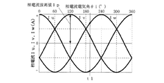
図2は同期モータ11のU相コイルUc,V相コイルVc及びW相コイルWcに正弦波通電(180°通電)を行っているときの相電流波形図であり、正弦波形を成すU相電流Iu,V相電流Iv及びW相電流Iwにはそれぞれ120°の位相差がある。
(1) Method for Detecting Phase Current Peak Value Ip and Phase Current Electrical Angle θi in Phase Current Peak Value / Electric
この相電流波形図からすれば、U相電流Iu,V相電流Iv及びW相電流Iwと、相電流波高値Ipと、相電流電気角θiには、
・Iu=Ip×cos(θi)
・Iv=Ip×cos(θi−2/3π)
・Iw=Ip×cos(θi+2/3π)
の式が成り立つ。
According to this phase current waveform diagram, the U-phase current Iu, the V-phase current Iv and the W-phase current Iw, the phase current peak value Ip, and the phase current electrical angle θi are:
・ Iu = Ip × cos (θi)
Iv = Ip × cos (θi−2 / 3π)
・ Iw = Ip × cos (θi + 2 / 3π)
The following equation holds.
相電流波高値・電気角検出部19における相電流波高値Ipと相電流電気角θiの検出は前記式が成り立つことを前提として行われるものであって、該検出は、相電流検出部17で検出されたU相電流Iu,V相電流Iv及びW相電流Iwを利用して、前記式による計算によって相電流波高値Ipと相電流電気角θiを求めることによってこれらの検出を行う。
The detection of the phase current peak value Ip and the phase current electrical angle θi in the phase current peak value / electrical
(2)誘起電圧波高値・電気角検出部20における誘起電圧波高値Epと誘起電圧電気角θeの検出方法
図3は同期モータ11のU相コイルUc,V相コイルVc及びW相コイルWcに正弦波通電(180°通電)を行っているときの誘起電圧波形図であり、正弦波形を成すU相誘起電圧Eu,V相誘起電圧Ev及びW相誘起電圧Ewにはそれぞれ120°の位相差がある。
(2) Detecting method of induced voltage peak value Ep and induced voltage electrical angle θe in induced voltage peak value / electrical
この誘起電圧波形図からすれば、U相誘起電圧Eu,V相誘起電圧Ev及びW相誘起電圧Ewと、誘起電圧波高値Epと、誘起電圧電気角θeには、
・Eu=Ep×cos(θe)
・Ev=Ep×cos(θe−2/3π)
・Ew=Ep×cos(θe+2/3π)
の式が成り立つ。
According to this induced voltage waveform diagram, the U-phase induced voltage Eu, the V-phase induced voltage Ev and the W-phase induced voltage Ew, the induced voltage peak value Ep, and the induced voltage electrical angle θe are:
Eu = Ep × cos (θe)
Ev = Ep × cos (θe−2 / 3π)
Ew = Ep × cos (θe + 2 / 3π)
The following equation holds.
一方、U相印加電圧Vu,V相印加電圧Vv及びW相印加電圧Vwと、U相電流Iu,V相電流Iv及びW相電流Iwと、U相コイル抵抗Ru,V相コイル抵抗Rv及びW相コイル抵抗Rwと、U相誘起電圧Eu,V相誘起電圧Ev及びW相誘起電圧Ewには、
・Vu−Iu×Ru=Eu
・Vv−Iv×Rv=Ev
・Vw−Iw×Rw=Ew
の式が成り立つ。
On the other hand, U-phase applied voltage Vu, V-phase applied voltage Vv and W-phase applied voltage Vw, U-phase current Iu, V-phase current Iv and W-phase current Iw, U-phase coil resistance Ru, V-phase coil resistance Rv and W The phase coil resistance Rw, U phase induced voltage Eu, V phase induced voltage Ev and W phase induced voltage Ew are:
・ Vu-Iu × Ru = Eu
・ Vv-Iv × Rv = Ev
・ Vw-Iw × Rw = Ew
The following equation holds.
誘起電圧波高値・電気角検出部20における誘起電圧波高値Epと誘起電圧電気角θeの検出は前記式が成り立つことを前提として行われるものであって、該検出は、相電流検出部17で検出されたU相電流Iu,V相電流Iv及びW相電流Iwと印加電圧検出部18で検出されたU相印加電圧Vu,V相印加電圧Vv及びW相印加電圧Vwを利用して、前記式(後者の式)からU相誘起電圧Eu,V相誘起電圧Ev及びW相誘起電圧Ewを求め、そして、求めたU相誘起電圧Eu,V相誘起電圧Ev及びW相誘起電圧Ewを利用して、前記式(前者の式)から誘起電圧波高値Epと誘起電圧電気角θeを求めることによって行われる。
The detection of the induced voltage peak value Ep and the induced voltage electrical angle θe in the induced voltage peak value / electrical
(3)ロータ位置検出部21におけるロータ位置θmの検出方法
ロータ位置検出部21におけるロータ位置θmの検出は、相電流波高値・電気角検出部19で検出された相電流電気角θiと予め用意されたデータテーブル(後述の(4)欄参照)から選定した電流位相βを利用して、
・θm=θi−β−90°
の式からロータ位置θmを求めることによって行われる。
(3) Method of Detecting Rotor Position θm in Rotor
・ Θm = θi-β-90 °
The rotor position θm is obtained from the following equation.
ここで用いられるデータテーブルは[相電流波高値Ip]及び[誘起電圧電気角θe−相電流電気角θi]をパラメータとして電流位相βを規定したものであって、所期の電流位相βを[相電流波高値Ip]及び[誘起電圧電気角θe−相電流電気角θi]をパラメータとして選定することができる。 The data table used here defines current phase β using [phase current peak value Ip] and [induced voltage electrical angle θe−phase current electrical angle θi] as parameters. The phase current peak value Ip] and [induced voltage electrical angle θe−phase current electrical angle θi] can be selected as parameters.
説明するまでもないが、[相電流波高値Ip]には相電流波高値・電気角検出部19で検出された相電流波高値Ipが該当し、また、[誘起電圧電気角θe−相電流電気角θi]には誘起電圧波高値・電気角検出部20で検出された誘起電圧電気角θeから相電流波高値・電気角検出部19で検出された相電流電気角θiを減算した値が該当する。
Needless to say, the phase current peak value Ip detected by the phase current peak value /
(4)ロータ位置検出部21でロータ位置θmを検出する際に用いられるデータテーブルの作成方法
図4は同期モータ11のロータが回転しているときのモータベクトル図であり、電圧V,電流I及び誘起電圧E(=ωΨ)の関係をd−q座標にベクトルで表してある。図中のVdは電圧Vのd軸成分、Vqは電圧Vのq軸成分、Idは電流Iのd軸成分、Iqは電流Iのq軸成分、Edは誘起電圧Eのd軸成分、Eqは誘起電圧Eのq軸成分、αはq軸を基準とした電圧位相、βはq軸を基準とした電流位相、γはq軸を基準とした誘起電圧位相である。また、図中のΨaはロータの永久磁石の磁束、Ldはd軸インダクタンス、Lqはq軸インダクタンス、Rはステータのコイルの抵抗、Ψはロータの総合鎖交磁束である。
(4) Method of creating data table used when rotor
このモータベクトル図からすれば、ロータの回転数をωとすると、 According to this motor vector diagram, if the rotational speed of the rotor is ω,

の式が成り立ち、また、同式の右辺からωに関する値を左辺に移すと、 When the value of ω is moved from the right side of the formula to the left side,
の式が成り立つ。 The following equation holds.
ロータ位置検出部21でロータ位置θmを検出する際に用いられるデータテーブルの作成は前記モータベクトル図下で前記式が成り立つことを前提として行われるものであって、該作成は、前記モータベクトル図に示した電流位相βと電流Iをそれぞれ所定範囲内で段階的に増加させながら〔誘起電圧位相γ−電流位相β〕が所定値のときの電流位相βを保存して、〔電流I〕に相当する[相電流波高値Ip]と〔誘起電圧位相γ−電流位相β〕に相当する[誘起電圧電気角θe−相電流電気角θi]をパラメータとした電流位相βのデータテーブルを作成することによって行われる。
The creation of the data table used when the rotor
詳しくは、図5に示すように、電流位相βを−180°から180°まで0.001°ずつ増加させ、且つ、電流Iを0Aから64まで1Aずつ増加させながら(ステップST1,ST2及びST5〜ST8参照)、同期モータ11固有のd軸インダクタンスLdとq軸インダクタンスLqを利用して前記モータベクトル図から電圧位相αと電流位相βと誘起電圧位相γを求め、そして、〔誘起電圧位相γ−電流位相β〕が1°,2°,3°…のときの電流位相βを保存する(ステップST3及びST4参照)。これにより、〔電流I〕に相当する[相電流波高値Ip]を1つのパラメータとし、且つ、〔誘起電圧位相γ−電流位相β〕に相当する[誘起電圧電気角θe−相電流電気角θi]を他のパラメータとする電流位相βのデータテーブルが作成される。
Specifically, as shown in FIG. 5, the current phase β is increased by 0.001 ° from −180 ° to 180 °, and the current I is increased by 1A from 0A to 64 (steps ST1, ST2, and ST5). To ST8), the voltage phase α, the current phase β, and the induced voltage phase γ are obtained from the motor vector diagram using the d-axis inductance Ld and the q-axis inductance Lq inherent to the
先に述べた(3)ロータ位置検出部21におけるロータ位置θmの検出方法、(4)ロータ位置検出部21でロータ位置θmを検出する際に用いられるデータテーブルの作成方法、は別の方法も採用可能であるため、以下にこれらについて順に詳述する。
There are other methods in addition to (3) the method for detecting the rotor position θm in the
(3’)ロータ位置検出部21におけるロータ位置θmの別の検出方法
ロータ位置検出部21におけるロータ位置θmの検出は、誘起電圧波高値・電気角検出部20で検出された誘起電圧電気角θeと予め用意されたデータテーブル(後述の(4’)欄参照)から選定した誘起電圧位相γを利用して、
・θm=θe−γ−90°
の式からロータ位置θmを求めることによって行われる。
(3 ′) Another Detection Method of Rotor Position θm in Rotor
・ Θm = θe−γ−90 °
The rotor position θm is obtained from the following equation.
ここで用いられるデータテーブルは[相電流波高値Ip]及び[誘起電圧電気角θe−相電流電気角θi]をパラメータとして誘起電圧位相γを規定したものであって、所期の誘起電圧位相γを[相電流波高値Ip]及び[誘起電圧電気角θe−相電流電気角θi]をパラメータとして選定することができる。 The data table used here defines the induced voltage phase γ using [phase current peak value Ip] and [induced voltage electrical angle θe−phase current electrical angle θi] as parameters, and the desired induced voltage phase γ. Can be selected using [phase current peak value Ip] and [induced voltage electrical angle θe−phase current electrical angle θi] as parameters.
説明するまでもないが、[相電流波高値Ip]には相電流波高値・電気角検出部19で検出された相電流波高値Ipが該当し、また、[誘起電圧電気角θe−相電流電気角θi]には誘起電圧波高値・電気角検出部20で検出された誘起電圧電気角θeから相電流波高値・電気角検出部19で検出された相電流電気角θiを減算した値が該当する。
Needless to say, the phase current peak value Ip detected by the phase current peak value /
(4’)ロータ位置検出部21でロータ位置θmを検出する際に用いられるデータテーブルの別の作成方法
ロータ位置検出部21でロータ位置θmを検出する際に用いられるデータテーブルの作成は、前記(4)と同様に、前記モータベクトル図下で前記式が成り立つことを前提として行われるものであって、該作成は、前記モータベクトル図に示した電流位相βと電流Iをそれぞれ所定範囲内で段階的に増加させながら〔誘起電圧位相γ−電流位相β〕が所定値のときの誘起電圧位相γを保存して、〔電流I〕に相当する[相電流波高値Ip]と〔誘起電圧位相γ−電流位相β〕に相当する[誘起電圧電気角θe−相電流電気角θi]をパラメータとした誘起電圧位相γのデータテーブルを作成することによって行われる。
(4 ′) Another method of creating a data table used when the rotor
詳しくは、図5と同様に、電流位相βを−180°から180°まで0.001°ずつ増加させ、且つ、電流Iを0Aから64まで1Aずつ増加させながら(ステップST1,ST2及びST5〜ST8参照)、同期モータ11固有のd軸インダクタンスLdとq軸インダクタンスLqを利用して前記モータベクトル図から電圧位相αと電流位相βと誘起電圧位相γを求め、そして、〔誘起電圧位相γ−電流位相β〕が1°,2°,3°…のときの誘起電圧位相γを保存する(ステップST3及びST4参照)。これにより、〔電流I〕に相当する[相電流波高値Ip]を1つのパラメータとし、且つ、〔誘起電圧位相γ−電流位相β〕に相当する[誘起電圧電気角θe−相電流電気角θi]を他のパラメータとする誘起電圧位相γのデータテーブルが作成される。
Specifically, as in FIG. 5, the current phase β is increased by 0.001 ° from −180 ° to 180 °, and the current I is increased by 1A from 0A to 64 (steps ST1, ST2 and ST5). ST8), the voltage phase α, the current phase β, and the induced voltage phase γ are obtained from the motor vector diagram using the d-axis inductance Ld and the q-axis inductance Lq inherent to the
このように、前述のモータ制御装置によれば、相電流波高値・電気角検出部19で検出された相電流波高値Ip及び相電流電気角θiと誘起電圧波高値・電気角検出部20で検出された誘起電圧波高値Ep及び誘起電圧電気角θeのうちの電流電気角θiを変数として含み、且つ、予め用意されたデータテーブルから[相電流波高値Ip]及び[誘起電圧電気角θe−相電流電気角θi]をパラメータとして選定可能な電流位相βを変数として含むロータ位置計算式(θm=θi−β−90°)、または、誘起電圧電気角θeを変数として含み、且つ、予め用意されたデータテーブルから[相電流波高値Ip]及び[誘起電圧電気角θe−相電流電気角θi]をパラメータとして選定可能な誘起電圧位相γを変数として含むロータ位置計算式(θm=θe−γ−90°)からロータ位置θmを直接的に求めることによって該ロータ位置θmを検出することができる。
Thus, according to the motor control device described above, the phase current peak value Ip and the phase current electrical angle θi detected by the phase current peak value /
つまり、所定のロータ位置計算式を用いてロータ位置θmを直接的に求めているので、従前の検出手法のように検出精度が変動することを回避して、ロータ位置θmを一定の精度下で確実に検出することができる。また、ロータ計算式に含まれる変数の1つである電流位相βまたは誘起電圧位相γを予め用意されたデータテーブルから選定する方式を採用しているので、電流位相βまたは誘起電圧位相γをその都度計算によって求める場合に比べて低い処理負荷にてロータ位置θmを簡単に検出することができ、従前の検出手法のように高処理負荷に対応した高能力のデータ処理装置を用いる必要性も無い。 That is, since the rotor position θm is obtained directly using a predetermined rotor position calculation formula, it is possible to avoid the detection accuracy from fluctuating as in the conventional detection method, and to reduce the rotor position θm under a certain accuracy. It can be detected reliably. In addition, since the current phase β or the induced voltage phase γ, which is one of the variables included in the rotor calculation formula, is selected from a data table prepared in advance, the current phase β or the induced voltage phase γ The rotor position θm can be easily detected with a low processing load compared to the case where it is obtained by calculation each time, and there is no need to use a high-performance data processing device corresponding to a high processing load unlike the conventional detection method. .
尚、前述の説明では、ロータ位置検出部21でロータ位置θmを検出する際に用いられるデータテーブルとして、[相電流波高値Ip]及び[誘起電圧電気角θe−相電流電気角θi]をパラメータとして電流位相βまたは誘起電圧位相γを規定したものを例示したが、[誘起電圧波高値Ep]及び[誘起電圧電気角θe−相電流電気角θi]をパラメータとして電流位相βまたは誘起電圧位相γを規定したデータテーブルや、[相電流波高値Ip]及び[誘起電圧波高値Ep]をパラメータとして電流位相βまたは誘起電圧位相γを規定したデータテーブルや、[相電流波高値Ip],[誘起電圧波高値Ep]及び[誘起電圧電気角θe−相電流電気角θi]をパラメータとして電流位相βまたは誘起電圧位相γを規定したデータテーブルを代わりに用いても前記同様の作用,効果を得ることができる。
In the above description, [phase current peak value Ip] and [induced voltage electrical angle θe−phase current electrical angle θi] are parameters as the data table used when the rotor
また、前述の説明では、同期モータ11として3相DCブラシレスモータを例示し、且つ、インバータ12として3相バイポーラ駆動方式インバータを例示したが、3相以外の同期モータ用のインバータを備えたモータ制御装置であれば、本発明を適用して前記同様の作用,効果を得ることができる。
In the above description, a three-phase DC brushless motor is exemplified as the
さらに、前述の説明では、同期モータ11の各相に流れる電流を検出するセンサの役割を為すシャント抵抗器Ru,Rv及びRwを該インバータ12に組み込んだモータ制御装置を例示したが、シャント抵抗器Ru,Rv及びRwをインバータ12の外に配置したモータ制御装置や、シャント抵抗器Ru,Rv及びRwに代えてこれと同等の役割を為すセンサ(例えばカレントトランスやホール素子を利用したセンサ等)を同一位置或いは他の位置に配置したモータ制御装置であっても、本発明を適用して前記同様の作用,効果を得ることができる。
Further, in the above description, the motor control device in which the shunt resistors Ru, Rv, and Rw that serve as sensors for detecting the currents flowing in the respective phases of the
さらに、前述の説明では、同期モータ11の各相に印加される電圧を検出するために同期モータ11とインバータ12との接続線からの分岐線を印加電圧検出部18に接続したモータ制御装置を例示したが、直流電源13の電圧とインバータ12のスイッチング素子のオンオフ量から計算すること等によって同期モータ11の各相に印加される電圧を検出できるようにしたモータ制御装置であっても、本発明を適用して前記同様の作用,効果を得ることができる。
Further, in the above description, the motor control device in which the branch line from the connection line between the
11…同期モータ、12…インバータ、13…直流電源、14…コントローラ、15……回転制御部、16…インバータ駆動部、17…相電流検出部、18…印加電圧検出部、19…相電流波高値・電気角検出部、20…誘起電圧波高値・電気角検出部、21…ロータ位置検出部。
DESCRIPTION OF
Claims (5)
同期モータのコイルに流れる電流を検出するための電流検出手段と、
同期モータのコイルに印加される電圧を検出するための印加電圧検出手段と、
電流検出手段で検出された電流に基づいて電流波高値及び電流電気角を検出するための電流波高値・電気角検出手段と、
電流検出手段で検出された電流と印加電圧検出手段で検出された印加電圧に基づいて誘起電圧波高値及び誘起電圧電気角を検出するための誘起電圧波高値・電気角検出手段と、
電流波高値・電気角検出手段で検出された電流波高値及び電流電気角と誘起電圧波高値・電気角検出手段で検出された誘起電圧波高値及び誘起電圧電気角のうちの電流電気角または誘起電圧電気角を変数として含み、且つ、予め用意されたデータテーブルから[電流波高値],[誘起電圧波高値」及び[誘起電圧電気角−電流電気角]の少なくとも2つをパラメータとして選定可能な電流位相または誘起電圧位相を変数として含むロータ位置計算式からロータ位置を直接的に求めることによって該ロータ位置を検出するためのロータ位置検出手段と、を備える。 A motor control device having a function of detecting a rotor position of a synchronous motor without a sensor,
Current detection means for detecting the current flowing in the coil of the synchronous motor;
Applied voltage detection means for detecting the voltage applied to the coil of the synchronous motor;
A current peak value / electrical angle detection means for detecting a current peak value and a current electrical angle based on the current detected by the current detection means;
An induced voltage peak value / electrical angle detection means for detecting an induced voltage peak value and an induced voltage electrical angle based on the current detected by the current detection means and the applied voltage detected by the applied voltage detection means;
Current peak value and current electrical angle detected by current peak value / electrical angle detection means and induced voltage peak value and induced voltage electrical angle detected by induced voltage peak value / electrical angle detection means The voltage electrical angle is included as a variable, and at least two of [current peak value], [induced voltage peak value], and [induced voltage peak angle-current electrical angle] can be selected from a data table prepared in advance. And a rotor position detecting means for detecting the rotor position by directly obtaining the rotor position from a rotor position calculation formula including the current phase or the induced voltage phase as a variable.
ロータ位置検出手段で用いられるデータテーブルは、[電流波高値]及び[誘起電圧電気角−電流電気角]をパラメータとして電流位相または誘起電圧位相を規定したものである。 The motor control device according to claim 1,
The data table used in the rotor position detection means defines the current phase or the induced voltage phase using [current peak value] and [induced voltage electrical angle−current electrical angle] as parameters.
ロータ位置検出手段におけるロータ位置計算式はロータ位置=電流電気角−電流位相−90°であり、同式中の電流位相はデータテーブルから[電流波高値]及び[誘起電圧電気角−電流電気角]をパラメータとして選定される。 The motor control device according to claim 2,
The rotor position calculation formula in the rotor position detection means is rotor position = current electrical angle−current phase−90 °, and the current phase in the formula is [current peak value] and [induced voltage electrical angle−current electrical angle] from the data table. ] Is selected as a parameter.
ロータ位置検出手段におけるロータ位置計算式はロータ位置=誘起電圧電気角−誘起電圧位相−90°であり、同式中の誘起電圧位相はデータテーブルから[電流波高値]及び[誘起電圧電気角−電流電気角]をパラメータとして選定される。 The motor control device according to claim 2,
The rotor position calculation formula in the rotor position detecting means is rotor position = induced voltage electrical angle−induced voltage phase−90 °, and the induced voltage phase in the formula is determined from the data table as “current peak value” and “induced voltage electrical angle− Current electrical angle] is selected as a parameter.
同期モータはステータに複数相のコイルを有する同期モータであり、
電流検出手段は同期モータの複数相のコイルそれぞれに流れる電流を検出し、
印加電圧検出手段は同期モータの複数相のコイルそれぞれに印加される電圧を検出する。 In the motor control device according to any one of claims 1 to 4,
The synchronous motor is a synchronous motor having a plurality of coils in the stator,
The current detection means detects the current flowing in each of the coils of the plurality of phases of the synchronous motor,
The applied voltage detection means detects the voltage applied to each of the plurality of phase coils of the synchronous motor.
Priority Applications (5)
| Application Number | Priority Date | Filing Date | Title |
|---|---|---|---|
| JP2009150933A JP5317849B2 (en) | 2009-06-25 | 2009-06-25 | Motor control device |
| US13/377,870 US8664906B2 (en) | 2009-06-25 | 2010-06-16 | Motor control device |
| PCT/JP2010/003982 WO2010150485A1 (en) | 2009-06-25 | 2010-06-16 | Motor control device |
| CN201080023183.9A CN102439839B (en) | 2009-06-25 | 2010-06-16 | Motor control device |
| EP10791809.6A EP2448105B1 (en) | 2009-06-25 | 2010-06-16 | Motor control device |
Applications Claiming Priority (1)
| Application Number | Priority Date | Filing Date | Title |
|---|---|---|---|
| JP2009150933A JP5317849B2 (en) | 2009-06-25 | 2009-06-25 | Motor control device |
Publications (2)
| Publication Number | Publication Date |
|---|---|
| JP2011010438A JP2011010438A (en) | 2011-01-13 |
| JP5317849B2 true JP5317849B2 (en) | 2013-10-16 |
Family
ID=43386273
Family Applications (1)
| Application Number | Title | Priority Date | Filing Date |
|---|---|---|---|
| JP2009150933A Active JP5317849B2 (en) | 2009-06-25 | 2009-06-25 | Motor control device |
Country Status (5)
| Country | Link |
|---|---|
| US (1) | US8664906B2 (en) |
| EP (1) | EP2448105B1 (en) |
| JP (1) | JP5317849B2 (en) |
| CN (1) | CN102439839B (en) |
| WO (1) | WO2010150485A1 (en) |
Families Citing this family (16)
| Publication number | Priority date | Publication date | Assignee | Title |
|---|---|---|---|---|
| JP5838032B2 (en) * | 2011-02-15 | 2015-12-24 | サンデンホールディングス株式会社 | Motor control device |
| JP5652610B2 (en) * | 2011-02-15 | 2015-01-14 | サンデン株式会社 | Motor control device |
| JP5697036B2 (en) * | 2011-04-22 | 2015-04-08 | サンデン株式会社 | Motor control device |
| JP5838038B2 (en) | 2011-04-22 | 2015-12-24 | サンデンホールディングス株式会社 | Motor control device |
| JP5748051B2 (en) * | 2011-05-10 | 2015-07-15 | サンデンホールディングス株式会社 | Synchronous motor applied voltage electrical angle setting method and motor control device |
| DE102011076734A1 (en) * | 2011-05-30 | 2012-12-06 | Robert Bosch Gmbh | Method and device for angle estimation in a synchronous machine |
| JP6232868B2 (en) * | 2012-10-23 | 2017-11-22 | 株式会社島津製作所 | Motor drive device and vacuum pump |
| DE102013204382A1 (en) * | 2013-03-13 | 2014-09-18 | Robert Bosch Gmbh | Control device and method for driving a rotary field machine |
| US9595903B2 (en) | 2015-03-20 | 2017-03-14 | General Electric Company | Controller for motor |
| JP6633399B2 (en) | 2016-01-27 | 2020-01-22 | サンデン・オートモーティブコンポーネント株式会社 | Motor control device |
| JP6646484B2 (en) | 2016-03-15 | 2020-02-14 | サンデン・オートモーティブコンポーネント株式会社 | Motor control device |
| JP6642311B2 (en) | 2016-07-12 | 2020-02-05 | 株式会社デンソー | Control device for rotating electric machine |
| JP6936172B2 (en) * | 2018-02-28 | 2021-09-15 | サンデン・オートモーティブコンポーネント株式会社 | Motor control device |
| JP6936171B2 (en) * | 2018-02-28 | 2021-09-15 | サンデン・オートモーティブコンポーネント株式会社 | Motor control device |
| CN108321845B (en) * | 2018-03-19 | 2021-04-02 | 电子科技大学 | Self-synchronizing grid-connected control device for inverter |
| CN109713953B (en) * | 2018-12-27 | 2021-02-09 | 峰岹科技(深圳)股份有限公司 | Single-phase BLDC motor no-position driving device |
Family Cites Families (9)
| Publication number | Priority date | Publication date | Assignee | Title |
|---|---|---|---|---|
| JP3358390B2 (en) | 1995-05-10 | 2002-12-16 | トヨタ自動車株式会社 | Synchronous motor rotation angular velocity detection device, rotation angle detection device, control device and control method for synchronous motor |
| JP2000278987A (en) * | 1999-03-19 | 2000-10-06 | Toshiba Corp | Inverter device |
| JP3454210B2 (en) * | 1999-11-30 | 2003-10-06 | 株式会社日立製作所 | Position sensorless control method for synchronous motor |
| JP2001352800A (en) * | 2000-06-08 | 2001-12-21 | Yaskawa Electric Corp | Constant identification method of synchronous motor and control unit with constant identification function therefor |
| CN1420620A (en) * | 2001-11-19 | 2003-05-28 | 乐金电子(天津)电器有限公司 | Device and method for testing rotor position of permasyn motor |
| JP4067949B2 (en) * | 2002-12-03 | 2008-03-26 | サンデン株式会社 | Motor control device |
| CN100364225C (en) * | 2003-06-30 | 2008-01-23 | 松下电器产业株式会社 | Sensorless motor driving device and its driving method |
| JP4716118B2 (en) * | 2006-03-29 | 2011-07-06 | 株式会社ジェイテクト | Motor control device |
| US8324851B2 (en) * | 2009-03-04 | 2012-12-04 | Rockwell Automation Technologies, Inc. | Method for determining a rotor position in a permanent magnet motor |
-
2009
- 2009-06-25 JP JP2009150933A patent/JP5317849B2/en active Active
-
2010
- 2010-06-16 CN CN201080023183.9A patent/CN102439839B/en active Active
- 2010-06-16 WO PCT/JP2010/003982 patent/WO2010150485A1/en active Application Filing
- 2010-06-16 EP EP10791809.6A patent/EP2448105B1/en active Active
- 2010-06-16 US US13/377,870 patent/US8664906B2/en active Active
Also Published As
| Publication number | Publication date |
|---|---|
| JP2011010438A (en) | 2011-01-13 |
| EP2448105B1 (en) | 2015-08-26 |
| US20120086375A1 (en) | 2012-04-12 |
| CN102439839B (en) | 2014-06-04 |
| CN102439839A (en) | 2012-05-02 |
| EP2448105A1 (en) | 2012-05-02 |
| WO2010150485A1 (en) | 2010-12-29 |
| EP2448105A4 (en) | 2013-05-01 |
| US8664906B2 (en) | 2014-03-04 |
Similar Documents
| Publication | Publication Date | Title |
|---|---|---|
| JP5317849B2 (en) | Motor control device | |
| JP5838032B2 (en) | Motor control device | |
| JP5652610B2 (en) | Motor control device | |
| KR102442060B1 (en) | Power apparatus, motor driving apparatus therein | |
| JP5748051B2 (en) | Synchronous motor applied voltage electrical angle setting method and motor control device | |
| JP5273451B2 (en) | Motor control device | |
| JP5697036B2 (en) | Motor control device | |
| JP5425173B2 (en) | Control device | |
| JP5898407B2 (en) | Motor control device | |
| US20190363658A1 (en) | Motor controlling method, motor controlling system, and electronic power steering system | |
| CN108781047B (en) | Motor control device | |
| WO2018025319A1 (en) | Control device for rotating electric machine | |
| US20200001915A1 (en) | Motor controlling method, motor controlling system, and electronic power steering system | |
| US20200007062A1 (en) | Motor controlling method, motor controlling system, and electronic power steering system | |
| JP2009100544A (en) | Motor controller | |
| JP2012005318A (en) | Motor controller and electric power steering device | |
| JP2006033976A (en) | Control device of synchronous motor | |
| US20200007063A1 (en) | Motor controlling method, motor controlling system, and electronic power steering system | |
| JP2022152604A (en) | Device for controlling rotary electric machine | |
| JP2012005286A (en) | Motor controller and electric power steering device | |
| JP2004180453A (en) | Control equipment of synchronous motor |
Legal Events
| Date | Code | Title | Description |
|---|---|---|---|
| A621 | Written request for application examination |
Free format text: JAPANESE INTERMEDIATE CODE: A621 Effective date: 20120210 |
|
| TRDD | Decision of grant or rejection written | ||
| A01 | Written decision to grant a patent or to grant a registration (utility model) |
Free format text: JAPANESE INTERMEDIATE CODE: A01 Effective date: 20130619 |
|
| A61 | First payment of annual fees (during grant procedure) |
Free format text: JAPANESE INTERMEDIATE CODE: A61 Effective date: 20130709 |
|
| R150 | Certificate of patent or registration of utility model |
Ref document number: 5317849 Country of ref document: JP Free format text: JAPANESE INTERMEDIATE CODE: R150 Free format text: JAPANESE INTERMEDIATE CODE: R150 |
|
| S533 | Written request for registration of change of name |
Free format text: JAPANESE INTERMEDIATE CODE: R313533 |
|
| R350 | Written notification of registration of transfer |
Free format text: JAPANESE INTERMEDIATE CODE: R350 |
|
| R250 | Receipt of annual fees |
Free format text: JAPANESE INTERMEDIATE CODE: R250 |
|
| R250 | Receipt of annual fees |
Free format text: JAPANESE INTERMEDIATE CODE: R250 |
|
| R250 | Receipt of annual fees |
Free format text: JAPANESE INTERMEDIATE CODE: R250 |
|
| R250 | Receipt of annual fees |
Free format text: JAPANESE INTERMEDIATE CODE: R250 |
|
| R250 | Receipt of annual fees |
Free format text: JAPANESE INTERMEDIATE CODE: R250 |
|
| R250 | Receipt of annual fees |
Free format text: JAPANESE INTERMEDIATE CODE: R250 |
|
| S533 | Written request for registration of change of name |
Free format text: JAPANESE INTERMEDIATE CODE: R313533 |
|
| R350 | Written notification of registration of transfer |
Free format text: JAPANESE INTERMEDIATE CODE: R350 |