JP5317656B2 - Image display device - Google Patents

Image display device Download PDF

Info

Publication number
JP5317656B2
JP5317656B2 JP2008310197A JP2008310197A JP5317656B2 JP 5317656 B2 JP5317656 B2 JP 5317656B2 JP 2008310197 A JP2008310197 A JP 2008310197A JP 2008310197 A JP2008310197 A JP 2008310197A JP 5317656 B2 JP5317656 B2 JP 5317656B2
Authority
JP
Japan
Prior art keywords
image display
heat
display panel
air
flow path
Prior art date
Legal status (The legal status is an assumption and is not a legal conclusion. Google has not performed a legal analysis and makes no representation as to the accuracy of the status listed.)
Active
Application number
JP2008310197A
Other languages
Japanese (ja)
Other versions
JP2010134198A5 (en
JP2010134198A (en
Inventor
雅哉 中道
信行 岳
正平 高橋
Current Assignee (The listed assignees may be inaccurate. Google has not performed a legal analysis and makes no representation or warranty as to the accuracy of the list.)
Sanyo Electric Co Ltd
Original Assignee
Sanyo Electric Co Ltd
Priority date (The priority date is an assumption and is not a legal conclusion. Google has not performed a legal analysis and makes no representation as to the accuracy of the date listed.)
Filing date
Publication date
Application filed by Sanyo Electric Co Ltd filed Critical Sanyo Electric Co Ltd
Priority to JP2008310197A priority Critical patent/JP5317656B2/en
Priority to EP09015004A priority patent/EP2194520A1/en
Priority to US12/629,988 priority patent/US20100142149A1/en
Publication of JP2010134198A publication Critical patent/JP2010134198A/en
Publication of JP2010134198A5 publication Critical patent/JP2010134198A5/ja
Application granted granted Critical
Publication of JP5317656B2 publication Critical patent/JP5317656B2/en
Active legal-status Critical Current
Anticipated expiration legal-status Critical

Links

Images

Abstract

<P>PROBLEM TO BE SOLVED: To provide an image display apparatus that is installed outdoors and prevents breakage of a circuit board for controlling an image display panel. <P>SOLUTION: In an image display apparatus, an accommodation room 121 is formed inside a case 12 having a waterproof structure, and the inside of the accommodation room 121 is provided with an image display panel 11 having a display screen 112a capable of being visually recognized from the surface side of the case 12. A back wall 125 forming the accommodation room 121 is arranged separately from the back surface 111 of the image display panel 11, and the circuit board for controlling the image display panel 11 is arranged on the back surface side of the back wall 125. <P>COPYRIGHT: (C)2010,JPO&amp;INPIT

Description

本発明は、画像表示装置に関し、特に屋外設置用の画像表示装置に関する。   The present invention relates to an image display device, and more particularly to an image display device for outdoor installation.

従来から、画像表示用のモニターとして、特許文献1に開示されている液晶ディスプレイなどの平面型ディスプレイが多く使用されている。従来の液晶ディスプレイのほとんどは、屋内に設置することを前提とした設計になっており、風雨やダストなどから液晶ディスプレイを保護する対策は施されていない。このため、従来の液晶ディスプレイを屋外に常設することは困難であった。   Conventionally, a flat display such as a liquid crystal display disclosed in Patent Document 1 is often used as an image display monitor. Most conventional liquid crystal displays are designed to be installed indoors, and no measures are taken to protect the liquid crystal display from wind and rain. For this reason, it has been difficult to permanently install a conventional liquid crystal display outdoors.

しかし近年、液晶ディスプレイを屋外に常設することが望まれている。その理由として、液晶ディスプレイは厚みが小さいこと、及び画像の解像度が高いことなどが挙げられる。厚みが小さいと、建物の外壁へのディスプレイの設置や、バス停留所などの狭い場所へのディスプレイの設置が可能となる。又、解像度が高いと、表示画面が小さくても画像を鮮明に映し出すことが可能となる。   However, in recent years, it has been desired to install a liquid crystal display outdoors. The reason for this is that the liquid crystal display has a small thickness and a high image resolution. When the thickness is small, it is possible to install a display on the outer wall of a building or a display in a narrow place such as a bus stop. In addition, when the resolution is high, an image can be clearly displayed even if the display screen is small.

そこで、液晶ディスプレイを風雨やダストから保護すべく、防水構造を有する収容室の内部に、液晶ディスプレイ、特に液晶ディスプレイのうち風雨やダストによって破損しやすい画像表示パネルを配備することが考えられている。
特開2005−286987号公報
Therefore, in order to protect the liquid crystal display from wind and rain and dust, it is considered that a liquid crystal display, in particular, an image display panel that is easily damaged by wind and rain among the liquid crystal display, is arranged in the interior of the housing having a waterproof structure. .
JP 2005-286987 A

しかし、画像表示パネルを収容室の内部に配備して防水すると、収容室の内部から外部への熱の逃げ道がなくなるため、画像表示パネルを自然空冷することが出来ない。このため、動作時に画像表示パネルから発生する熱や太陽光などによって、画像表示パネルの温度が上昇し、液晶の本来の機能が低下して画像表示が不能になるといった現象(ブラックアウト)が生じてしまう。   However, if the image display panel is placed inside the storage room and waterproofed, there is no way for heat to escape from the inside of the storage room to the outside, and thus the image display panel cannot be naturally cooled. For this reason, a phenomenon (blackout) occurs in which the temperature of the image display panel rises due to heat or sunlight generated from the image display panel during operation, the original function of the liquid crystal deteriorates, and the image display becomes impossible. End up.

又、画像表示パネルから発生した熱は、画像表示パネルを制御するための回路基板の温度をも上昇させてしまう虞がある。画像表示パネルの動作時においては、回路基板は、自身から発生する熱によっても温度が上昇するため、画像表示パネルの熱が回路基板に加わると、回路基板の温度が過度に上昇して回路基板が破損する虞がある。   Further, the heat generated from the image display panel may increase the temperature of the circuit board for controlling the image display panel. During the operation of the image display panel, the temperature of the circuit board rises due to the heat generated from the circuit board. Therefore, when the heat of the image display panel is applied to the circuit board, the temperature of the circuit board increases excessively. May be damaged.

これらの問題点を解消すべく、画像表示パネルや回路基板を冷却することが考えられるが、画像表示パネルから発生する熱量を大きいため、画像表示パネルと回路基板の両方を効率良く冷却することが困難であった。   In order to solve these problems, it is conceivable to cool the image display panel and the circuit board. However, since the amount of heat generated from the image display panel is large, it is possible to efficiently cool both the image display panel and the circuit board. It was difficult.

そこで本発明の目的は、屋外に設置可能な画像表示装置であって、画像表示パネルを制御するための回路基板が破損しにくい画像表示装置を提供することである。   SUMMARY OF THE INVENTION An object of the present invention is to provide an image display device that can be installed outdoors, and that is less likely to damage a circuit board for controlling an image display panel.

本発明に係る画像表示装置は、防水構造を有する筐体(12)の内部に収容室(121)が形成され、該収容室(121)の内部には、前記筐体(12)の表面側から視認可能な画面を有する画像表示パネル(11)が配備されている。前記収容室(121)を形成する背面壁(125)は、前記画像表示パネル(11)の背面(111)から離間して配置され、該背面壁(125)の背面側には、前記画像表示パネル(11)を制御する回路基板(11e)が配備されている。   In the image display device according to the present invention, a housing chamber (121) is formed inside a housing (12) having a waterproof structure, and the housing chamber (121) has a surface side of the housing (12). An image display panel (11) having a screen that can be visually recognized is provided. A back wall (125) forming the storage chamber (121) is disposed apart from the back surface (111) of the image display panel (11), and the image display is provided on the back side of the back wall (125). A circuit board (11e) for controlling the panel (11) is provided.

上記画像表示装置によれば、防水構造を有する筐体(12)の収容室(121)の内部に画像表示パネル(11)を配備することにより、画像表示装置(11)を屋外に設置したときに風雨やダストから該画像表示パネル(11)を保護することが出来る。
又、収容室(121)を形成する背面壁(125)が、画像表示パネル(11)の背面(111)から離間して配置されているので、画像表示パネル(11)で発生した熱は背面壁(125)に伝わりにくい。従って、背面壁(125)の背面に配備されている回路基板(11e)には、画像表示パネル(11)の熱が殆ど伝わらず、その結果、回路基板(11e)の温度が過度に上昇して破損するということが防止されることとなる。
According to the image display device, when the image display device (11) is installed outdoors by disposing the image display panel (11) in the housing chamber (121) of the housing (12) having a waterproof structure. In addition, the image display panel (11) can be protected from wind and rain and dust.
Further, since the back wall (125) forming the storage chamber (121) is arranged away from the back surface (111) of the image display panel (11), the heat generated in the image display panel (11) Hard to be transmitted to the wall (125). Therefore, the heat of the image display panel (11) is hardly transmitted to the circuit board (11e) disposed on the back surface of the back wall (125), and as a result, the temperature of the circuit board (11e) excessively increases. It will be prevented from being damaged.

具体的構成において、前記画像表示パネル(11)の背面側又は画像表示パネル(11)の下方には、前記画像表示パネル(11)から発生する熱を回収する熱交換器(191)が配備され、前記背面壁(125)は、少なくとも一部の領域が該熱交換器によって冷却される。   In a specific configuration, a heat exchanger (191) for recovering heat generated from the image display panel (11) is disposed on the back side of the image display panel (11) or below the image display panel (11). The back wall (125) is at least partially cooled by the heat exchanger.

他の具体的な構成において、前記収容室(121)内部には、前記画像表示パネル(11)から発生する熱を回収する熱交換器(191)が配備され、前記背面壁(125)は、少なくとも一部の領域が該熱交換器によって冷却される。   In another specific configuration, a heat exchanger (191) that recovers heat generated from the image display panel (11) is disposed inside the storage chamber (121), and the back wall (125) At least a portion of the region is cooled by the heat exchanger.

又、上記具体的構成において、前記筐体(12)の内部には、前記収容室(121)の外側に、前記熱交換器(191)により回収された熱を前記筐体(12)の外部に放出する第2の熱交換器(192)が配備されている。   In the specific configuration described above, the heat recovered by the heat exchanger (191) is outside the housing (12) inside the housing (12), outside the housing chamber (121). A second heat exchanger (192) is provided for discharge to the

上記具体的構成によれば、画像表示パネル(11)から発生した熱を回収する熱交換器(191)を用いて、回路基板(11e)で発生した熱をも回収することが可能となる。しかも、画像表示パネル(11)で発生した熱は回路基板(11e)に殆ど伝わらないので、回路基板(11e)の冷却が、熱交換器(191)によって効率良く行われることとなる。   According to the specific configuration, the heat generated in the circuit board (11e) can be recovered using the heat exchanger (191) that recovers the heat generated from the image display panel (11). Moreover, since the heat generated in the image display panel (11) is hardly transmitted to the circuit board (11e), the circuit board (11e) is efficiently cooled by the heat exchanger (191).

より具体的な構成において、前記背面壁(125)の背面には、前記熱交換器(191)によって冷却される領域に、該背面上に存在する空気から熱を集める集熱手段(71)が配備されている。
該具体的構成によれば、背面壁(125)の背面上に存在する空気を媒体として、該背面に配備されている回路基板(11e)から熱を回収することが可能となる。
In a more specific configuration, a heat collecting means (71) for collecting heat from the air existing on the back surface is provided in a region cooled by the heat exchanger (191) on the back surface of the back wall (125). Has been deployed.
According to this specific configuration, it is possible to recover heat from the circuit board (11e) arranged on the back surface using air existing on the back surface of the back wall (125) as a medium.

又、前記背面壁(125)の背面には、前記熱交換器(191)によって冷却される領域上に存在する空気を、前記背面壁(125)の背面に沿って流す送風手段(72)が配備されている。
該具体的構成によれば、熱交換器(191)に冷却された空気を、背面壁の背面に配備されている回路基板(11e)に送り込むことが出来、その結果、回路基板が効率良く冷却されることとなる。
In addition, on the back surface of the back wall (125), air blowing means (72) for flowing air existing on the region cooled by the heat exchanger (191) along the back surface of the back wall (125). Has been deployed.
According to the specific configuration, the air cooled in the heat exchanger (191) can be sent to the circuit board (11e) disposed on the back surface of the back wall, and as a result, the circuit board is efficiently cooled. Will be.

上記画像表示装置の更に他の具体的構成において、前記収容室(121)の内部には、前記画像表示パネル(11)を包囲する循環流路(92)が形成されると共に、該循環流路(92)に沿って空気を循環させる循環手段(18)が配備されている。前記循環流路(92)は、前記収容室(121)を形成する表面壁(124)と前記画像表示パネル(11)の表面(112)との間を該表面(112)に沿って鉛直方向に延びる第1流路部(11a)と、前記収容室(121)を形成する背面壁(125)と前記画像表示パネル(11)の背面(111)との間を該背面(111)に沿って鉛直方向に延びる第2流路部(11c)とを有し、第1流路部(11a)と第2流路部(11c)は、それぞれの上端部と下端部で互いに連通している。   In still another specific configuration of the image display device, a circulation channel (92) surrounding the image display panel (11) is formed inside the storage chamber (121), and the circulation channel Circulation means (18) for circulating air along (92) is provided. The circulation channel (92) is vertically arranged along the surface (112) between the surface wall (124) forming the storage chamber (121) and the surface (112) of the image display panel (11). The first flow path portion (11a) extending in the direction between the back wall (125) forming the storage chamber (121) and the back surface (111) of the image display panel (11) along the back surface (111). And a second flow path portion (11c) extending in the vertical direction, and the first flow path portion (11a) and the second flow path portion (11c) communicate with each other at the upper end portion and the lower end portion thereof. .

上記具体的構成によれば、画像表示パネル(11)を包囲する循環流路(92)内の空気を循環手段(18)によって循環させることによって、画像表示パネル(11)で発生した熱は、空気を媒体として熱交換器(191)へ導かれ、そして該熱交換器(191)よって回収される。従って、熱交換器(191)での熱交換効率が高まることとなる。
更に、回路基板(11e)で発生した熱も、背面壁(125)の表面から循環流路(92)内を循環する空気に伝わって、熱交換器(191)で回収される。このようにして、回路基板(11e)も冷却されることとなる。
According to the specific configuration described above, the air generated in the image display panel (11) is circulated by the circulation means (18) by circulating the air in the circulation channel (92) surrounding the image display panel (11). Air is led to the heat exchanger (191) as a medium and is recovered by the heat exchanger (191). Therefore, the heat exchange efficiency in the heat exchanger (191) is increased.
Furthermore, the heat generated in the circuit board (11e) is also transferred from the surface of the back wall (125) to the air circulating in the circulation flow path (92) and is recovered by the heat exchanger (191). In this way, the circuit board (11e) is also cooled.

本発明に係る画像表示装置によれば、画像表示パネルを制御するための回路基板が破損しにくく、屋外に設置することが可能である。   According to the image display device of the present invention, the circuit board for controlling the image display panel is not easily damaged and can be installed outdoors.

以下、本発明の実施の形態に係る画像表示装置を搭載した画像表示システムにつき、図面に沿って具体的に説明する。
1.画像表示システムの概要
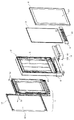
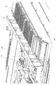
画像表示システムは、図1に示されるような扁平な直方体状の外観を呈しており、図2に示されるように、画像表示装置1、支持台2、背板3、カバー4、照明器具5、及び一対の通気用プレート6,6を具えている。
画像表示装置1は、画像表示システムの表面101に映像を映し出す装置であり、図5に示される様に、液晶ディスプレイ10を具えている。尚、画像表示装置1の詳細については、「2.画像表示装置について」で説明する。
Hereinafter, an image display system equipped with an image display device according to an embodiment of the present invention will be specifically described with reference to the drawings.
1. 1. Overview of Image Display System The image display system has a flat rectangular parallelepiped appearance as shown in FIG. 1, and as shown in FIG. 2, the image display device 1, the support base 2, the back plate 3, and the cover 4, a lighting fixture 5, and a pair of ventilation plates 6, 6.
The image display device 1 is a device that displays an image on the surface 101 of the image display system, and includes a liquid crystal display 10 as shown in FIG. The details of the image display device 1 will be described in “2. About the image display device”.

支持台2は、画像表示装置1及び背板3を支持するためのものであり、支持台2には、画像表示装置1及び背板3を取り付けるためのフレーム部21が形成されている。フレーム部21は、画像表示装置1及び背板3を嵌め込むことが可能な構成を有する。尚、画像表示装置1を支持台2に取り付けるための構造については、「3.画像表示装置を支持台に取り付けるための構成について」で説明する。   The support table 2 is for supporting the image display device 1 and the back plate 3, and the support table 2 is formed with a frame portion 21 for attaching the image display device 1 and the back plate 3. The frame unit 21 has a configuration in which the image display device 1 and the back plate 3 can be fitted. The structure for attaching the image display device 1 to the support base 2 will be described in “3. Configuration for attaching the image display device to the support base”.

背板3は、広告物を貼付する設置台であり、画像表示装置1の背面側においてフレーム部21に設置されている。広告物は、背板3の表面31、即ち画像表示システムの背面102側の面に貼付される。
ここで、背板3は、照明器具5から発せられた光を透過すべく、光透過性を有する材質から形成されている。又、背板3に貼付される広告物も、照明器具5から発せられた光を透過すべく、光透過性を有する材質から形成されている。尚、以下では、光透過性を有する材質から形成された広告物を広告フィルムという。
The back plate 3 is an installation base on which an advertisement is attached, and is installed on the frame portion 21 on the back side of the image display device 1. The advertisement is attached to the surface 31 of the back plate 3, that is, the surface on the back surface 102 side of the image display system.
Here, the back plate 3 is formed of a light-transmitting material so as to transmit light emitted from the lighting fixture 5. Further, the advertising matter attached to the back plate 3 is also made of a light-transmitting material so as to transmit light emitted from the lighting fixture 5. In the following, an advertisement formed from a light-transmitting material is referred to as an advertisement film.

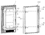
カバー4は、開閉可能に支持台2に取り付けられており、閉じ位置において広告物が貼付される背板3の表面31を覆うことが出来る。これにより、背板3の表面31に貼付された広告物が、カバー4によって保護されることとなる。
又、カバー4のうち背板3の表面31と対向する部分は、光透過性を有する材質によって形成されている。これにより、画像表示システムの背面102側から広告物を視認することが可能になっている。
The cover 4 is attached to the support base 2 so as to be openable and closable, and can cover the surface 31 of the back plate 3 on which the advertisement is pasted in the closed position. Thereby, the advertising matter stuck to the surface 31 of the back plate 3 is protected by the cover 4.
Moreover, the part which opposes the surface 31 of the backplate 3 among the covers 4 is formed with the material which has a light transmittance. Thereby, it is possible to visually recognize the advertisement from the back surface 102 side of the image display system.

照明器具5は、背板3の表面31に貼付される広告フィルムを照明する器具であり、略鉛直方向に延びた複数の蛍光灯によって構成されている。そして、照明器具5は、画像表示装置1と背板3との間に位置にて、支持台2のフレーム部21に取り付けられている。尚、照明器具5が配置される具体的な位置については、「4.照明器具の配置について」で説明する。
照明器具5によって広告フィルムを照らすことにより、夜間でも広告フィルムに印刷された文字等を視認することが可能である。
The lighting fixture 5 is a fixture that illuminates an advertising film attached to the surface 31 of the back plate 3, and is constituted by a plurality of fluorescent lamps extending in a substantially vertical direction. The lighting fixture 5 is attached to the frame portion 21 of the support base 2 at a position between the image display device 1 and the back plate 3. In addition, the specific position where the lighting fixture 5 is arrange | positioned is demonstrated in "4. About arrangement | positioning of a lighting fixture."
By illuminating the advertisement film with the lighting fixture 5, it is possible to visually recognize characters printed on the advertisement film even at night.

一対の通気用プレート6,6は、画像表示装置1の下方位置にて、画像表示システムの前面101と背面102に1つずつ配備されている。一対の通気用プレート6,6には、画像表示システムの内部と外部とを連通する複数の通気口61が形成されている。   A pair of ventilation plates 6, 6 are arranged one by one on the front surface 101 and the back surface 102 of the image display system at a position below the image display device 1. The pair of ventilation plates 6 and 6 are formed with a plurality of ventilation holes 61 that communicate the inside and the outside of the image display system.

上記画像表示システムは、図3に示される様に、バス停留所などの交通機関の停留所に設置される。これにより、停留所で待機している利用者に対して、種々の情報を静止画や動画によって提供することが出来る。尚、画像表示システムの具体的な設置状態については、「5.画像表示システムの設置状態について」で説明する。   As shown in FIG. 3, the image display system is installed at a transportation stop such as a bus stop. Thereby, various information can be provided to the user who is waiting at the bus stop as a still image or a moving image. A specific installation state of the image display system will be described in “5. Installation state of image display system”.

又、画像表示システムを有線又は無線で遠隔操作することにより、画像表示装置1によって表示画面112aに映し出す情報を更新することが出来る。更に、複数のバス停留所のそれぞれに画像表示システムを設置した場合、それらの画像表示システムを一括して管理することが出来る。   Further, the information displayed on the display screen 112a by the image display device 1 can be updated by remotely operating the image display system by wire or wireless. Furthermore, when an image display system is installed at each of a plurality of bus stops, these image display systems can be managed collectively.

2.画像表示装置について
画像表示装置1は、図4及び図5に示されるように、液晶ディスプレイ10、筺体12、複数のヒートパイプ13、循環用ファン18、放熱フィン14、通気用ファン15,16、及び集熱フィン17を具える。更に図12に示される様に、画像表示装置1には、空気調和機19、循環用ファン181、及び断熱部材7、並びに回路基板用の集熱フィン71と送風ファン72も具えられている。
2. As shown in FIGS. 4 and 5, the image display device 1 includes a liquid crystal display 10, a housing 12, a plurality of heat pipes 13, a circulation fan 18, a radiation fin 14, ventilation fans 15, 16, And heat collecting fins 17. Further, as shown in FIG. 12, the image display device 1 also includes an air conditioner 19, a circulation fan 181, a heat insulating member 7, a heat collecting fin 71 for a circuit board, and a blower fan 72.

<液晶ディスプレイ10>
液晶ディスプレイ10は平面型ディスプレイであり、図5に示される様に、画像表示パネル11と、画像表示パネル11を制御するための回路基板11eとを具える。画像表示パネル11は、後述する収容室121の内部に配備されると共に、回路基板11eは、該収容室121を形成する背面壁125の背面に配備されている。
<Liquid crystal display 10>
The liquid crystal display 10 is a flat display, and includes an image display panel 11 and a circuit board 11e for controlling the image display panel 11, as shown in FIG. The image display panel 11 is provided inside a storage chamber 121 described later, and the circuit board 11 e is provided on the back surface of the back wall 125 that forms the storage chamber 121.

画像表示パネル11には、用途に応じて種々の形状のものを用いることが出来る。本実施の形態では、バス停留所などの狭い場所に画像表示システムを設置することが可能となるように、画像表示パネル11として、縦長の長方形状のものが用いられている。尚、画像表示パネル11は、特に表示画面112aが形成されている表面112において発熱しやすく高温になりやすい。   The image display panel 11 can have various shapes depending on the application. In the present embodiment, a vertically long rectangular shape is used as the image display panel 11 so that the image display system can be installed in a narrow place such as a bus stop. Note that the image display panel 11 tends to generate heat at a surface 112 on which the display screen 112a is formed, and tends to become high temperature.

<筺体12>
(収容室について)
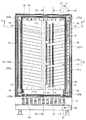
筺体12は防水構造を有し、筐体12の内部には、図4に示される様に収容室121が形成されている。収容室121の内部には、図12に示されるように画像表示パネル11が、表示画面112aを画像表示システムの表面101の方に向けて配備されている。
<Housing 12>
(Containment room)
The housing 12 has a waterproof structure, and a housing chamber 121 is formed inside the housing 12 as shown in FIG. As shown in FIG. 12, the image display panel 11 is arranged inside the storage chamber 121 with the display screen 112a facing the surface 101 of the image display system.

具体的には図4或いは図12に示される様に、筐体12は、画像表示パネル11の表面112側に位置する表面壁124と、画像表示パネル11の背面111側に位置する背面壁125と、画像表示パネル11の両側面側に位置する側面壁121a,121bと、画像表示パネル11の上端面113側に位置する上面壁127(図13も参照)と、画像表示パネル11の下端面114側に位置する下面壁128(図14も参照)とを有する。
そして、収容室121は、表面壁124、背面壁125、側面壁121a,121b、上面壁127、及び下面壁128によって構成され、密閉又はほぼ密閉された状態で維持されている。
Specifically, as shown in FIG. 4 or FIG. 12, the housing 12 includes a front wall 124 positioned on the front surface 112 side of the image display panel 11 and a rear wall 125 positioned on the rear surface 111 side of the image display panel 11. Side wall 121a, 121b located on both sides of the image display panel 11, an upper wall 127 (see also FIG. 13) located on the upper end surface 113 side of the image display panel 11, and a lower end surface of the image display panel 11. And a lower wall 128 (see also FIG. 14) located on the side of 114.
The storage chamber 121 includes a front wall 124, a back wall 125, side walls 121a and 121b, an upper surface wall 127, and a lower surface wall 128, and is maintained in a sealed or almost sealed state.

このように、収容室121を密閉又はほぼ密閉された状態に維持すると共に、該収容室121の内部に画像表示パネル11を収容することによって、画像表示装置1を屋外に設置した場合でも、風雨やダストから画像表示パネル11を保護することが出来る。   As described above, even when the image display device 1 is installed outdoors by maintaining the storage chamber 121 in a sealed or almost sealed state and storing the image display panel 11 in the storage chamber 121, The image display panel 11 can be protected from dust and dust.

本実施の形態では図12に示される様に、背面壁125は、画像表示パネル11と背板3との間に位置にて、画像表示パネル11の背面111から離間して配置されている。これにより、画像表示パネル11で発生した熱は背面壁125に伝わりにくく、従って、背面壁125の背面に配備されている回路基板11eには、画像表示パネル11の熱が殆ど伝わらない。その結果、回路基板11eの温度が過度に上昇して破損するということが防止されることとなる。   In the present embodiment, as shown in FIG. 12, the back wall 125 is disposed at a position between the image display panel 11 and the back plate 3 and spaced from the back surface 111 of the image display panel 11. Thereby, the heat generated in the image display panel 11 is hardly transmitted to the back wall 125, and therefore, the heat of the image display panel 11 is hardly transmitted to the circuit board 11e disposed on the back surface of the back wall 125. As a result, the temperature of the circuit board 11e is prevented from excessively rising and being damaged.

又、表面壁124は、表面壁124のうち画像表示パネル11の表示画面112aと対向する部分が、光透過性を有する材質、具体的にはガラス材によって形成されている。尚、表面壁124の表面は、画像表示システムの表面101となる。これにより、筐体12の表面側、即ち画像表示システムの表面101側から、画像表示パネル11の表示画面112aを視認することが可能になっている。   In the surface wall 124, a portion of the surface wall 124 that faces the display screen 112 a of the image display panel 11 is formed of a light transmissive material, specifically, a glass material. Note that the surface of the surface wall 124 is the surface 101 of the image display system. Thereby, the display screen 112a of the image display panel 11 can be visually recognized from the surface side of the housing 12, that is, the surface 101 side of the image display system.

(循環流路について)
収容室121の内部には、図11及び図12に示される様に、画像表示パネル11を包囲する循環流路92が形成されている。尚、図11及び図12では、循環流路92を明確にすべく、ヒートパイプ13及び集熱フィン17の図示を省略しており、後述する図13及び図14においても同様である。
(About the circulation channel)
As shown in FIGS. 11 and 12, a circulation channel 92 that surrounds the image display panel 11 is formed inside the storage chamber 121. 11 and 12, the illustration of the heat pipe 13 and the heat collecting fins 17 is omitted in order to clarify the circulation flow path 92, and the same applies to FIGS. 13 and 14 described later.

本実施の形態では循環流路92は、4つの流路部11a〜11dによって構成されている。流路部11aは、収容室121を形成する表面壁124と画像表示パネル11の表面112との間に形成され、表面112に沿って略鉛直方向に延びている。
具体的には図5に示される様に、流路部11aを形成するための一対の流路形成部材921,921が、画像表示パネル11の表面112に配備されている。一対の流路形成部材921,921は、画像表示パネル11の表示画面112aの両側の位置にて画像表示パネル11の表面112に沿って鉛直方向に延びると共に、収容室112を形成する表面壁124と画像表示パネル11の表面112とによって挟まれている(図9参照)。これにより、一対の流路形成部材921,921と、収容室112を形成する表面壁124と、画像表示パネル11の表面112とによって囲まれた流路部11aが形成されることとなる。
In the present embodiment, the circulation flow path 92 is constituted by four flow path portions 11a to 11d. The flow path portion 11 a is formed between the surface wall 124 that forms the storage chamber 121 and the surface 112 of the image display panel 11, and extends in a substantially vertical direction along the surface 112.
Specifically, as shown in FIG. 5, a pair of flow path forming members 921 and 921 for forming the flow path portion 11 a is provided on the surface 112 of the image display panel 11. The pair of flow path forming members 921 and 921 extends in the vertical direction along the surface 112 of the image display panel 11 at positions on both sides of the display screen 112 a of the image display panel 11 and also has a surface wall 124 that forms the storage chamber 112. And the surface 112 of the image display panel 11 (see FIG. 9). As a result, the flow path portion 11 a surrounded by the pair of flow path forming members 921 and 921, the surface wall 124 that forms the storage chamber 112, and the surface 112 of the image display panel 11 is formed.

又、流路部11bは、図13に示される様に、収容室121を形成する上面壁127と画像表示パネル11の上端面113との間に形成されている。流路部11cは、収容室121を形成する背面壁125と画像表示パネル11の背面111との間に形成され、背面111に沿って略鉛直方向に沿って延びている。流路部11dは、図14に示される様に、収容室121を形成する下面壁128と画像表示パネル11の下端面114との間に形成されている。   Further, as shown in FIG. 13, the flow path portion 11 b is formed between the upper surface wall 127 forming the accommodation chamber 121 and the upper end surface 113 of the image display panel 11. The channel portion 11 c is formed between the back wall 125 forming the storage chamber 121 and the back surface 111 of the image display panel 11, and extends along the substantially vertical direction along the back surface 111. As shown in FIG. 14, the flow path portion 11 d is formed between the lower surface wall 128 that forms the accommodation chamber 121 and the lower end surface 114 of the image display panel 11.

本実施の形態においては、循環流路92を構成する流路部11aは、画像表示パネル11の外面に垂直な方向についての幅W(図12参照)が流路部11cよりも小さくなっている。具体的には、流路部11aの幅Wは10mm程度である。同様に、流路部11b,11dの幅Wも10mm程度である。   In the present embodiment, the flow path portion 11a constituting the circulation flow path 92 has a width W (see FIG. 12) in the direction perpendicular to the outer surface of the image display panel 11 smaller than the flow path portion 11c. . Specifically, the width W of the flow path portion 11a is about 10 mm. Similarly, the width W of the channel portions 11b and 11d is also about 10 mm.

流路部11a〜11dは、画像表示パネル11の周囲でこの順に環状に繋がって、画像表示パネル11を包囲している。即ち、流路部11aと流路部11cは、それぞれの上端部と下端部で、流路部11b及び流路部11dによって互いに連通している。
そして、循環流路92内の空気は、後述するように循環用ファン18,181によって画像表示パネル11の周囲を循環する。よって、画像表示パネル11の表示画面112aで発生した熱は、循環流路92内の空気を媒体として、画像表示パネル11の背面111側へ移動することとなる。
The flow path portions 11 a to 11 d are connected in a ring shape in this order around the image display panel 11 to surround the image display panel 11. That is, the flow path part 11a and the flow path part 11c are communicated with each other by the flow path part 11b and the flow path part 11d at the upper end and the lower end, respectively.
The air in the circulation channel 92 circulates around the image display panel 11 by the circulation fans 18 and 181 as will be described later. Therefore, the heat generated on the display screen 112a of the image display panel 11 moves to the back surface 111 side of the image display panel 11 using the air in the circulation channel 92 as a medium.

(通気路について)
筐体12の内部には、収容室121の外側の位置に、筐体12の外部に通じる通気路122,123が形成されている。具体的には図4に示されるように、通気路122は、収容室121を形成する一方の側面壁121aに沿って略鉛直方向に延び、通気路123は、収容室121を形成する他方の側面壁121bに沿って延びている。
このように、収容室121の両側に通気路122,123を形成することにより、画像表示装置1が厚み方向に大型化することを回避することが出来る。
(About air passage)
Inside the housing 12, air passages 122 and 123 communicating with the outside of the housing 12 are formed at positions outside the housing chamber 121. Specifically, as shown in FIG. 4, the ventilation path 122 extends in a substantially vertical direction along one side wall 121 a that forms the accommodation chamber 121, and the ventilation path 123 serves as the other side that forms the accommodation chamber 121. It extends along the side wall 121b.
Thus, by forming the air passages 122 and 123 on both sides of the storage chamber 121, it is possible to avoid the image display device 1 from being enlarged in the thickness direction.

通気路122の上端部122aは、図6に示されるようにクランク状に曲がっており、支持台2のフレーム部21の上面21aに設けられた通気口62(図8参照)を介して、筐体12の外部に通じている。通気路123の上端部123aについても同様である。
通気路122の下端部122bは、図7に示されるように、画像表示装置1の下方に設置されている通気用プレート6の通気口61を介して、筐体12の外部に通じている。通気路123の下端部123bについても同様である。
As shown in FIG. 6, the upper end portion 122 a of the air passage 122 is bent in a crank shape, and the housing is formed through a vent 62 (see FIG. 8) provided in the upper surface 21 a of the frame portion 21 of the support base 2. It leads to the outside of the body 12. The same applies to the upper end 123a of the air passage 123.
As shown in FIG. 7, the lower end portion 122 b of the air passage 122 communicates with the outside of the housing 12 through the air vent 61 of the air vent plate 6 installed below the image display device 1. The same applies to the lower end 123b of the air passage 123.

<ヒートパイプ13>
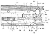
複数のヒートパイプ13は、循環流路92の流路部11c内に配備されている。具体的には複数のヒートパイプ13は、図4に示されるように画像表示パネル11の背面111に、略鉛直方向に所定間隔で繰り返し配列された状態で固定されている。そして、本実施の形態では、このように配列されたヒートパイプ13が、背面111の中心線111aの両側に1組ずつ配備されている。
<Heat pipe 13>
The plurality of heat pipes 13 are arranged in the flow path portion 11 c of the circulation flow path 92. Specifically, as shown in FIG. 4, the plurality of heat pipes 13 are fixed to the back surface 111 of the image display panel 11 in a state of being repeatedly arranged at predetermined intervals in a substantially vertical direction. In the present embodiment, the heat pipes 13 arranged in this way are arranged one by one on both sides of the center line 111a of the back surface 111.

中心線111aに対して通気路122側に配列されたヒートパイプ13は、図9に示される様に、画像表示パネル11の背面111から通気路122の方へと延び、そして収容室121を形成する一方の側面壁121aを貫通して、収容室121の内部から外部、具体的には収容室121の内部から通気路122の内部に延びている。即ち、ヒートパイプ13は、通気路122の内部に突出した状態で配置されている。   As shown in FIG. 9, the heat pipes 13 arranged on the air passage 122 side with respect to the center line 111 a extend from the back surface 111 of the image display panel 11 toward the air passage 122, and form a storage chamber 121. One side wall 121a is penetrated from the inside of the storage chamber 121 to the outside, specifically, from the inside of the storage chamber 121 to the inside of the air passage 122. That is, the heat pipe 13 is arranged in a state of protruding into the air passage 122.

より具体的には、図9に示される様に、収容室121を形成する側面壁121aに貫通孔126が形成されており、ヒートパイプ13は、貫通孔126を通って収容室121の内部から通気路122の内部に延びている。   More specifically, as shown in FIG. 9, a through-hole 126 is formed in the side wall 121 a that forms the storage chamber 121, and the heat pipe 13 passes from the inside of the storage chamber 121 through the through-hole 126. It extends inside the air passage 122.

そして、ヒートパイプ13には、図17及び図19に示される様に、シリコンゴム等からなる環状のシール部材132が嵌め込まれており、貫通孔126は、ヒートパイプ13が貫通した状態で、該ヒートパイプ13に嵌め込まれているシール部材132によってシールされている。これにより、収容室121の内部は密閉された状態のまま維持される。   As shown in FIGS. 17 and 19, an annular seal member 132 made of silicon rubber or the like is fitted into the heat pipe 13. It is sealed by a sealing member 132 fitted in the heat pipe 13. Thereby, the inside of the storage chamber 121 is maintained in a sealed state.

中心線111aに対して通気路123側に配列されたヒートパイプ13は、通気路122に延びたヒートパイプ13と同様に、収容室121を形成する他方の側面壁121bを貫通して、収容室121の内部から通気路123の内部に延びている(図5参照)。   The heat pipes 13 arranged on the air passage 123 side with respect to the center line 111a penetrate the other side wall 121b forming the housing chamber 121 in the same manner as the heat pipe 13 extending to the air passage 122, and the housing chamber It extends from the inside of 121 to the inside of the air passage 123 (see FIG. 5).

上記ヒートパイプ13によれば、画像表示パネル11から発生した熱を収容室121の内部で回収することが出来る。即ち、ヒートパイプ13によって、循環流路92を流れる空気から熱を回収し、また画像表示パネル11の熱を背面111から直接回収することが出来る。そして、回収された熱は、ヒートパイプ13によって収容室121の外側に導かれ、通気路122,123の内部に放出される。つまり、ヒートパイプ13は、画像表示装置1に具えられた熱交換手段として機能する。   According to the heat pipe 13, the heat generated from the image display panel 11 can be recovered inside the storage chamber 121. That is, the heat pipe 13 can recover heat from the air flowing through the circulation channel 92 and can directly recover the heat of the image display panel 11 from the back surface 111. Then, the recovered heat is guided to the outside of the accommodation chamber 121 by the heat pipe 13 and released into the ventilation paths 122 and 123. That is, the heat pipe 13 functions as a heat exchange unit provided in the image display device 1.

ヒートパイプ13から通気路122,123の内部に放出された熱は、通気路122,123を通って筺体12の外部に発散される。即ち、通気路122,123は、収容室121の外部においてヒートパイプ13に配備され、ヒートパイプ13から熱を回収する熱回収手段として機能する。
よって、画像表示パネル11の温度上昇が抑制され、その結果、液晶ディスプレイ10の機能は良好な状態に維持されることとなる。
The heat released from the heat pipe 13 into the air passages 122 and 123 is dissipated outside the housing 12 through the air passages 122 and 123. That is, the air passages 122 and 123 are provided in the heat pipe 13 outside the storage chamber 121 and function as heat recovery means for recovering heat from the heat pipe 13.
Therefore, the temperature rise of the image display panel 11 is suppressed, and as a result, the function of the liquid crystal display 10 is maintained in a good state.

又、本実施の形態においては、ヒートパイプ13は、画像表示パネル11の背面111に所定間隔で繰り返し配列されているので、循環流路92の流路部11c全体から熱を回収し、また液晶ディスプレイの背面111全体から熱を回収することが出来る。これにより、画像表示装置1の冷却効率が高くなる。   In the present embodiment, the heat pipes 13 are repeatedly arranged at predetermined intervals on the back surface 111 of the image display panel 11, so that heat is recovered from the entire flow path portion 11 c of the circulation flow path 92, and the liquid crystal Heat can be recovered from the entire back surface 111 of the display. Thereby, the cooling efficiency of the image display apparatus 1 becomes high.

画像表示パネル11が発熱することによって、収容室121の内部の温度は外部(通気路122,123)の温度よりも高くなる。又、ヒートパイプ13の内部には熱交換用の冷媒(水など)が充填されている。
そこで、ヒートパイプ13の熱交換効率を高めるという観点から、ヒートパイプ13を、図4に示される様に、収容室121の内部から通気路122,123の内部へ斜め上方に向かって延びるように配置することが好ましい。
When the image display panel 11 generates heat, the temperature inside the storage chamber 121 becomes higher than the temperature outside (air passages 122 and 123). The heat pipe 13 is filled with a heat exchange refrigerant (such as water).
Therefore, from the viewpoint of increasing the heat exchange efficiency of the heat pipe 13, the heat pipe 13 extends obliquely upward from the inside of the housing chamber 121 to the inside of the ventilation paths 122 and 123 as shown in FIG. 4. It is preferable to arrange.

これにより、ヒートパイプ13のうち、通気路122,123の内部に位置する部分(低温部分)が、収容室121の内部に位置する部分(高温部分)よりも、略鉛直方向において高くなる。よって、ヒートパイプ13内の冷媒は、高温部分で気化されて低温部分に向かって上昇し、そして、低温部分で液化されて高温部分に方へ流れ落ち、再び高温部分で気化される。
このように、ヒートパイプ13を斜めに配置することにより、冷媒がヒートパイプ13内を効率良く循環し、ヒートパイプ13の熱交換効率が高められることとなる。
Thereby, the part (low temperature part) located inside the ventilation paths 122 and 123 among the heat pipes 13 becomes higher in the substantially vertical direction than the part (high temperature part) located inside the storage chamber 121. Therefore, the refrigerant in the heat pipe 13 is vaporized in the high temperature portion and rises toward the low temperature portion, and is liquefied in the low temperature portion, flows down to the high temperature portion, and is vaporized again in the high temperature portion.
Thus, by arranging the heat pipes 13 at an angle, the refrigerant circulates efficiently in the heat pipes 13 and the heat exchange efficiency of the heat pipes 13 is enhanced.

更に、本実施の形態においては、画像表示パネル11の背面111にヒートパイプ13が配備されているので、ヒートパイプ13を表面112側(流路部11a内)に配置した場合に生じる制限、例えば表示画面112aの縮小や、画像表示装置1の大型化などを回避することが出来る。
このようにヒートパイプ13を背面111に配置した場合でも、表示画面112aで発生した熱は、循環流路92内を循環する空気によってヒートパイプ13に導かれるので、ヒートパイプ13での熱交換効率は高いままである。
Furthermore, in the present embodiment, since the heat pipe 13 is provided on the back surface 111 of the image display panel 11, a limitation that occurs when the heat pipe 13 is arranged on the front surface 112 side (in the flow path portion 11a), for example, Reduction of the display screen 112a and enlargement of the image display device 1 can be avoided.
Even when the heat pipe 13 is arranged on the back surface 111 in this way, the heat generated on the display screen 112 a is guided to the heat pipe 13 by the air circulating in the circulation flow path 92, and thus the heat exchange efficiency in the heat pipe 13. Remains high.

ヒートパイプ13の配置についてさらに説明すると、上記ヒートパイプ13は何れも、画像表示パネル11の背面111からの熱の回収効率を高めるという観点から、画像表示パネル11の背面111に沿って配置されている。   The arrangement of the heat pipes 13 will be further described. All the heat pipes 13 are arranged along the back surface 111 of the image display panel 11 from the viewpoint of increasing the efficiency of collecting heat from the back surface 111 of the image display panel 11. Yes.

本実施の形態では、画像表示パネル11の取付け位置と、画像表示装置1に搭載される電子部品や回路基板11eの取付け位置との関係から、画像表示パネル11の背面111には、図5及び図10に示されるように段差が形成されている。このような段差がある場合でも、図5及び図10に示される様に、ヒートパイプ13が画像表示パネル11の背面111に沿うように、段差の部分でヒートパイプ13がクランク状に曲げられている。   In the present embodiment, because of the relationship between the mounting position of the image display panel 11 and the mounting position of the electronic components and the circuit board 11e mounted on the image display device 1, the rear surface 111 of the image display panel 11 is shown in FIG. Steps are formed as shown in FIG. Even when there is such a step, as shown in FIGS. 5 and 10, the heat pipe 13 is bent in a crank shape at the step so that the heat pipe 13 follows the back surface 111 of the image display panel 11. Yes.

これにより、ヒートパイプ13の配備によって生じる無駄なスペースを縮小することが出来る。又、画像表示パネル11の背面111との接触面積が増大するので、ヒートパイプ13と画像表示パネル11との熱交換効率が高まり、その結果、画像表示パネル11の背面111からの熱の回収効率が高まることとなる。   Thereby, the useless space which arises by arrangement | positioning of the heat pipe 13 can be reduced. Moreover, since the contact area with the back surface 111 of the image display panel 11 increases, the heat exchange efficiency between the heat pipe 13 and the image display panel 11 increases, and as a result, the heat recovery efficiency from the back surface 111 of the image display panel 11. Will increase.

更に、本実施の形態では、ヒートパイプ13は何れも、図4に示されるように略鉛直方向に所定間隔で繰り返し配置されており、隣接するヒートパイプ13との距離を所定間隔に保ったまま通気路122,123の内部まで延びている。このため、通気路122の内部においても、ヒートパイプ13は、略鉛直方向へ所定間隔で繰り返し並んでいる。
よって、ヒートパイプ13で回収した熱を、通気路122,123の内部において分散して放出することが出来、その結果、通気路122,123の内部でのヒートパイプ13の熱交換(放熱)効率が高まることとなる。
Furthermore, in this embodiment, all the heat pipes 13 are repeatedly arranged at a predetermined interval in the substantially vertical direction as shown in FIG. 4, and the distance from the adjacent heat pipes 13 is kept at a predetermined interval. It extends to the inside of the air passages 122 and 123. For this reason, the heat pipes 13 are repeatedly arranged at predetermined intervals in the substantially vertical direction also in the ventilation path 122.
Therefore, the heat recovered by the heat pipe 13 can be dispersed and released inside the air passages 122 and 123, and as a result, the heat exchange (heat radiation) efficiency of the heat pipe 13 inside the air passages 122 and 123. Will increase.

<空気調和機19>
空気調和機19は、図2並びに図10〜図12に示されるように、蒸発器191と凝縮器192とから構成され、蒸発器191によって熱を回収し、回収した熱を凝縮器192によって放出する。
<Air conditioner 19>
As shown in FIG. 2 and FIGS. 10 to 12, the air conditioner 19 includes an evaporator 191 and a condenser 192, recovers heat by the evaporator 191, and releases the recovered heat by the condenser 192. To do.

蒸発器191は、図11及び図12に示される様に、収容室121の内部において、画像表示パネル11の背面111側であって、且つ画像表示パネル11の下端面114近傍の位置に配備されている。即ち、蒸発器191は、循環流路92の流路部11cの下端部に配置されている。このように、蒸発器191を画像表示パネル11の背面111側に配置することにより、画像表示装置1が高さ方向に大型化することを回避することが出来る。
又、蒸発器191を、画像表示パネル11の下端面114側ではなく、背面111側に配置することにより、循環流路92を短くすることが出来る。
As shown in FIG. 11 and FIG. 12, the evaporator 191 is disposed inside the storage chamber 121 at a position on the back surface 111 side of the image display panel 11 and in the vicinity of the lower end surface 114 of the image display panel 11. ing. That is, the evaporator 191 is disposed at the lower end of the flow path portion 11 c of the circulation flow path 92. Thus, by arranging the evaporator 191 on the back surface 111 side of the image display panel 11, it is possible to avoid the image display device 1 from being enlarged in the height direction.
In addition, the circulation channel 92 can be shortened by disposing the evaporator 191 not on the lower end surface 114 side of the image display panel 11 but on the back surface 111 side.

尚、蒸発器191は、画像表示パネル11の下方、即ち画像表示パネル11の下端面114側に配置されてもよい。   The evaporator 191 may be disposed below the image display panel 11, that is, on the lower end surface 114 side of the image display panel 11.

更に図14に示される様に、蒸発器191は、循環流路92の流路部11cの下端部において、収容室121を形成する背面壁125に近接して配置されている。これにより、背面壁125は、その下端近傍の領域が蒸発器191によって冷却されることとなる。   Further, as shown in FIG. 14, the evaporator 191 is disposed in the lower end portion of the flow path portion 11 c of the circulation flow path 92 in the vicinity of the back wall 125 that forms the storage chamber 121. Thereby, the area | region of the back wall 125 vicinity of the lower end will be cooled by the evaporator 191. FIG.

凝縮器192は、図11及び図12に示される様に、筐体12の内部であって、且つ収容室121の外側の位置に配備されている。具体的には、凝縮器192は、収容室121の下方位置、即ち画像表示パネル11の下方位置にて、一対の通気用プレート6,6の間に配置されている。   As shown in FIGS. 11 and 12, the condenser 192 is disposed inside the housing 12 and outside the storage chamber 121. Specifically, the condenser 192 is disposed between the pair of ventilation plates 6 and 6 at a position below the storage chamber 121, that is, a position below the image display panel 11.

又、一対の通気用プレート6,6の間には吸排気用ファンが配置されている(図示せず)。該吸排気用ファンは、一方の通気用プレート6に形成されている通気口61から空気を吸い込んで、凝縮器192に送り込み、そして他方の通気用プレート6に形成されている通気口61から空気を排出する。
これにより、凝縮器192から発散される熱を、筐体12の外部に効率良く放出することが出来る。
An intake / exhaust fan is disposed between the pair of ventilation plates 6 and 6 (not shown). The intake / exhaust fan sucks air from a vent 61 formed in one vent plate 6, sends it to the condenser 192, and air from a vent 61 formed in the other vent plate 6. Is discharged.
Thereby, the heat dissipated from the condenser 192 can be efficiently released to the outside of the housing 12.

尚、本実施の形態では、図10〜図12並びに図14において矢印Dで示される様に、前面101に配備されている通気用プレート6の通気口61から空気が吸い込まれ、背面102に配備されている通気用プレート6の通気口61から空気が排出される。即ち、前者の通気口61は吸気口として用いられ、後者の通気口61は排気口として用いられている。   In the present embodiment, as indicated by an arrow D in FIGS. 10 to 12 and 14, air is sucked from the vent 61 of the vent plate 6 provided on the front face 101 and provided on the rear face 102. Air is exhausted from the vent 61 of the venting plate 6. That is, the former vent 61 is used as an inlet and the latter vent 61 is used as an exhaust.

上記空気調和機19によれば、蒸発器191及び凝縮器192の何れにおいても熱交換効率が高いので、循環流路92内を流れる空気から熱を蒸発器191によって効率良く回収し、そして凝縮器192によって、通気用プレート6に形成された複数の通気口61から筐体12の外部に、熱を効率良く放出することが出来る。よって、画像表示パネル11で発生した熱が、空気調和機19によって回収されることとなり、画像表示パネル11の温度上昇が抑制され、その結果、画像表示パネル11の機能は良好な状態に維持されることとなる。   According to the air conditioner 19, since the heat exchange efficiency is high in both the evaporator 191 and the condenser 192, heat is efficiently recovered by the evaporator 191 from the air flowing in the circulation passage 92, and the condenser By 192, heat can be efficiently released from the plurality of vent holes 61 formed in the vent plate 6 to the outside of the housing 12. Therefore, the heat generated in the image display panel 11 is recovered by the air conditioner 19, and the temperature rise of the image display panel 11 is suppressed. As a result, the function of the image display panel 11 is maintained in a good state. The Rukoto.

又は、本実施の形態においては、背面壁125の下端近傍の領域が蒸発器191によって冷却されるので、画像表示パネル11から発生した熱を回収する蒸発器191を用いて、回路基板11eで発生した熱をも回収することが可能となる。しかも、上述したように、画像表示パネル11で発生した熱は回路基板11eに殆ど伝わらないので、回路基板11eの冷却が、蒸発器191によって効率良く行わることとなる。
尚、本実施の形態においては、後述するように、蒸発器191を用いたより効率的な回路基板11eの冷却が、回路基板用の集熱フィン71と送風ファン72によって可能となっている。
Alternatively, in the present embodiment, since the region near the lower end of the back wall 125 is cooled by the evaporator 191, it is generated by the circuit board 11 e using the evaporator 191 that recovers the heat generated from the image display panel 11. It is also possible to recover the generated heat. In addition, as described above, since the heat generated in the image display panel 11 is hardly transmitted to the circuit board 11e, the circuit board 11e is efficiently cooled by the evaporator 191.
In the present embodiment, as will be described later, the circuit board 11e can be more efficiently cooled using the evaporator 191 by the heat collecting fins 71 and the blower fan 72 for the circuit board.

本実施の形態では、循環流路92内の空気から熱を回収するための熱交換手段として蒸発器191を用い、蒸発器191で回収した熱を筐体12の外部に放出するために熱交換手段として凝縮器192を用いたが、蒸発器191及び凝縮器192に替えて他の熱交換手段を採用してもよい。
又、本実施の形態では、通気口61から空気を吸排気するための吸排気手段として吸排気用ファンを用いたが、吸排気用ファンに替えて他の吸排気手段を採用してもよい。
In the present embodiment, an evaporator 191 is used as a heat exchange means for recovering heat from the air in the circulation channel 92, and heat exchange is performed to release the heat recovered by the evaporator 191 to the outside of the housing 12. Although the condenser 192 is used as the means, other heat exchange means may be adopted instead of the evaporator 191 and the condenser 192.
In the present embodiment, the intake / exhaust fan is used as the intake / exhaust means for intake / exhaust air from the vent 61, but other intake / exhaust means may be employed instead of the intake / exhaust fan. .

更に、本実施の形態においては、通気用プレート6と筐体12とを別部材とし、通気用プレート6に通気口61を形成したが、通気用プレート6を設けずに、筐体12に通気口61を形成してもよい。   Further, in the present embodiment, the ventilation plate 6 and the housing 12 are separate members and the ventilation holes 61 are formed in the ventilation plate 6. The mouth 61 may be formed.

<循環用ファン18,181>
循環用ファン18,181は、循環流路92内の空気を循環流路92に沿って循環させるためのファンである。循環用ファン18は、図11及び図12に示される様に、画像表示パネル11の背面111側であって、且つ画像表示パネル11の上端面113近傍の位置に配備されている。即ち、循環用ファン18は、循環流路92の流路部11cの上端部に配備されている。
そして、循環用ファン18は、図13に示される様に、循環流路92の流路部11c内の空気を下方に向けて流す。
<Circulating fans 18, 181>
The circulation fans 18 and 181 are fans for circulating the air in the circulation channel 92 along the circulation channel 92. As shown in FIGS. 11 and 12, the circulation fan 18 is disposed on the back surface 111 side of the image display panel 11 and in the vicinity of the upper end surface 113 of the image display panel 11. That is, the circulation fan 18 is disposed at the upper end of the flow path portion 11 c of the circulation flow path 92.
Then, as shown in FIG. 13, the circulation fan 18 causes the air in the flow path portion 11c of the circulation flow path 92 to flow downward.

循環用ファン181は、収容室121の内部において、画像表示パネル11の背面111側であって、且つ蒸発器191の近傍に配備されている。本実施の形態では、図11及び図12に示される様に、循環流路92の流路部11cの下端部において、蒸発器191の上方位置に配備されている。
そして、循環用ファン181は、図14に示される様に、蒸発器191に向けて風を送り込む。
The circulation fan 181 is disposed inside the housing chamber 121 on the back surface 111 side of the image display panel 11 and in the vicinity of the evaporator 191. In this Embodiment, as FIG.11 and FIG.12 shows, in the lower end part of the flow-path part 11c of the circulation flow path 92, it arrange | positions in the upper position of the evaporator 191. As shown in FIG.
Then, the circulation fan 181 sends wind toward the evaporator 191 as shown in FIG.

これにより、循環流路92内の空気は、図13及び図14に示される様に、画像表示パネル11の周囲を実線矢印の方向へ循環することとなる。
即ち、循環用ファン18,181を駆動することによって、画像表示パネル11の表面112に沿う流路部11a内の空気は、図13に示される様に、略鉛直方向において下から上へ流れ、そして画像表示パネル11の上端面113に沿う流路部11bを通って、背面111に沿う流路部11cへ流れ込む。流路部11c内に流れ込んだ空気は、図14に示される様に、流路部11cに沿って上から下へ流れ、そして画像表示パネル11の下端面114に沿う流路11dを通って流路部11aに戻る。
As a result, the air in the circulation channel 92 circulates around the image display panel 11 in the direction of the solid arrow as shown in FIGS. 13 and 14.
That is, by driving the circulation fans 18 and 181, the air in the flow path portion 11 a along the surface 112 of the image display panel 11 flows from the bottom to the top in the substantially vertical direction, as shown in FIG. Then, it flows through the flow path portion 11 b along the upper end surface 113 of the image display panel 11 and flows into the flow path portion 11 c along the back surface 111. As shown in FIG. 14, the air that has flowed into the flow path portion 11c flows from the top to the bottom along the flow path portion 11c, and flows through the flow path 11d along the lower end surface 114 of the image display panel 11. Return to the road 11a.

上記循環用ファン18,181によれば、画像表示パネル11の表面112に沿う流路部11a内の空気を、背面111に沿う流路部11cに効率良く導くことが出来る。よって、画像表示パネル11の表示画面112aで発生した熱は、空気を媒体として、画像表示パネル11の背面111側に配備されているヒートパイプ13及び蒸発器191へ導かれ、そしてヒートパイプ13及び蒸発器191によって効率良く回収されることとなる。即ち、循環流路92内の空気を用いて、画像表示パネル11、特に画像表示パネル11の表示画面112aを空冷することが出来る。
よって、画像表示パネル11の温度上昇、特に発熱しやすい画像表示パネル11の表示画面112aの温度上昇が抑制され、その結果、画像表示パネルの機能は良好な状態に維持されることとなる。
According to the circulation fans 18 and 181, the air in the flow path portion 11 a along the surface 112 of the image display panel 11 can be efficiently guided to the flow path portion 11 c along the back surface 111. Therefore, the heat generated on the display screen 112a of the image display panel 11 is guided to the heat pipe 13 and the evaporator 191 disposed on the back surface 111 side of the image display panel 11 using air as a medium, and the heat pipe 13 and It will be efficiently recovered by the evaporator 191. That is, the air in the circulation channel 92 can be used to air-cool the image display panel 11, particularly the display screen 112 a of the image display panel 11.
Therefore, the temperature rise of the image display panel 11, especially the temperature rise of the display screen 112a of the image display panel 11 that easily generates heat is suppressed, and as a result, the function of the image display panel is maintained in a good state.

又、回路基板11eで発生した熱も、背面壁125の表面から循環流路92内を循環する空気に伝わって、ヒートパイプ13及び蒸発器191によって回収される。このようにして、回路基板11eも冷却されることとなる。   Further, the heat generated in the circuit board 11 e is also transmitted from the surface of the back wall 125 to the air circulating in the circulation flow path 92 and is recovered by the heat pipe 13 and the evaporator 191. In this way, the circuit board 11e is also cooled.

尚、循環用ファン18,181、ヒートパイプ13、及び蒸発器191によって画像表示パネル11や回路基板11eが冷却されることに鑑みれば、循環用ファン18,181、ヒートパイプ13、及び蒸発器191によって冷却機構が構成されていると把握することが出来る。   Considering that the image display panel 11 and the circuit board 11e are cooled by the circulation fans 18 and 181, the heat pipe 13, and the evaporator 191, the circulation fans 18 and 181, the heat pipe 13, and the evaporator 191 are used. It can be grasped that the cooling mechanism is configured.

本実施の形態においては、循環用ファン181によって蒸発器191に向けて風が送り込まれるので(図14参照)、循環流路92内の空気を、流路部11cで停滞させることなく蒸発器191に送り込むことが出来る。よって、蒸発器191によって熱を効率良く回収することが可能となる。   In the present embodiment, since the wind is sent toward the evaporator 191 by the circulation fan 181 (see FIG. 14), the evaporator 191 does not stagnate the air in the circulation passage 92 in the passage portion 11c. Can be sent to. Therefore, heat can be efficiently recovered by the evaporator 191.

又、本実施の形態においては、循環用ファン18,181が流路部11cの上端部と下端部のそれぞれに配備されているので、空気が循環流路92に沿って流れやすくなると共に、流速が大きくなる。従って、画像表示パネル11を均一に冷却することが可能となり、その結果、画像表示パネル11のうち蒸発器191近傍の部分だけが冷えるということがなくなる。   Further, in the present embodiment, the circulation fans 18 and 181 are arranged at the upper end portion and the lower end portion of the flow path portion 11c, so that the air can easily flow along the circulation flow path 92 and the flow velocity. Becomes larger. Therefore, the image display panel 11 can be uniformly cooled, and as a result, only the portion near the evaporator 191 in the image display panel 11 is not cooled.

但し、循環流路92内を流れる空気の流速を大きくし過ぎると、ヒートパイプ13や蒸発器191での熱交換効率が低下する。よって、本実施の形態では、図4に示される様に流路部11cの上端部に10個の循環用ファン18を配備する一方、流路部11cの下端部には、図15及び図16に示される様に3個の循環用ファン181を配備することが好ましい。   However, if the flow velocity of the air flowing through the circulation flow path 92 is excessively increased, the heat exchange efficiency in the heat pipe 13 and the evaporator 191 is lowered. Therefore, in the present embodiment, as shown in FIG. 4, ten circulation fans 18 are arranged at the upper end portion of the flow path portion 11c, while at the lower end portion of the flow path portion 11c, FIGS. It is preferable to provide three circulation fans 181 as shown in FIG.

又、本実施の形態においては、循環流路92を構成する流路部11aの幅W(=W1)が、流路部11cの幅W(=W2)よりも小さいので(図12参照)、循環流路92に沿って流れる空気の流速が、流路部11a内において大きくなる。従って、画像表示パネル11の表示画面112aからヒートパイプ13及び蒸発器191に導かれる熱量が増大し、その結果、表示画面112aの冷却効率が高まることとなる。   In the present embodiment, the width W (= W1) of the flow path portion 11a constituting the circulation flow path 92 is smaller than the width W (= W2) of the flow path portion 11c (see FIG. 12). The flow velocity of the air flowing along the circulation flow path 92 increases in the flow path portion 11a. Therefore, the amount of heat guided from the display screen 112a of the image display panel 11 to the heat pipe 13 and the evaporator 191 increases, and as a result, the cooling efficiency of the display screen 112a increases.

更に、本実施の形態においては、画像表示パネル11の表面112に沿う流路部11a内の空気が、略鉛直方向において下から上に流れるので、熱によって温まった空気は上昇するという空気の性質と相俟って、流路部11a内の空気は効率良く下から上へ流れることとなる。
よって、循環流路92に沿って空気が循環しやすくなり、画像表示パネル11の表示画面112aで発生した熱を、効率良くヒートパイプ13及び蒸発器191に導くことが出来る。その結果、ヒートパイプ13及び蒸発器191での熱交換(集熱)効率が高まり、以って画像表示装置1の冷却効率がより高まることとなる。
Further, in the present embodiment, since the air in the flow path portion 11a along the surface 112 of the image display panel 11 flows from the bottom to the top in the substantially vertical direction, the property of the air that the air warmed by heat rises. In combination with this, the air in the flow path portion 11a efficiently flows from the bottom to the top.
Therefore, air easily circulates along the circulation flow path 92, and the heat generated on the display screen 112a of the image display panel 11 can be efficiently guided to the heat pipe 13 and the evaporator 191. As a result, the heat exchange (heat collection) efficiency in the heat pipe 13 and the evaporator 191 is increased, and thus the cooling efficiency of the image display device 1 is further increased.

更に又、本実施の形態においては、循環用ファン18を、循環流路92の流路部11cの上端部、即ち画像表示パネル11の上端面113に沿う流路部11bから空気が流れ出る位置又はその近傍の位置に配置し、流路部11c内の空気を下方に向けて流しているので、循環流路92内の空気を効率良く循環させることが出来る。理由は以下のとおりである。   Furthermore, in the present embodiment, the circulation fan 18 is moved to a position where air flows out from the upper end portion of the flow passage portion 11c of the circulation flow passage 92, that is, the flow passage portion 11b along the upper end surface 113 of the image display panel 11. Since it arrange | positions in the position of the vicinity and flows the air in the flow-path part 11c toward the downward direction, the air in the circulation flow path 92 can be circulated efficiently. The reason is as follows.

循環流路92のうち、幅Wが狭い部分では流路抵抗が高く、幅Wが広い部分では流路抵抗が低いので、循環する過程で幅Wの狭い部分を流れている空気は、幅Wが広い部分へ流れ出ようとする。
本実施の形態における循環流路92では、図13に示されるように、流路部11a,11bの幅W(=W1,W2)が流路部11cの幅Wよりも狭いので、流路部11a,11bの流路抵抗は流路部11cの流路抵抗よりも高く、従って流路部11a,11bを流れる空気は、流路部11cの方へ流れ出ようとする。
In the circulation channel 92, the flow resistance is high in the narrow width W portion and the flow resistance is low in the wide width portion. Therefore, the air flowing through the narrow width portion in the circulation process is Tries to flow into a wide area.
In the circulation flow path 92 in the present embodiment, as shown in FIG. 13, the width W (= W1, W2) of the flow path portions 11a and 11b is narrower than the width W of the flow path portion 11c. The flow path resistances of 11a and 11b are higher than the flow path resistance of the flow path part 11c. Therefore, the air flowing through the flow path parts 11a and 11b tends to flow toward the flow path part 11c.

よって、流路部11bから空気が流れ出る位置またはその近傍の位置に循環用ファン18を配置し、流路部11b内の空気を流路部11cの方に流すことにより、流路部11b内の空気は効率良く流路部11cへ導かれる。その結果、循環流路92内の空気が効率良く循環されることとなる。   Therefore, the circulation fan 18 is disposed at a position where the air flows out from the flow path portion 11b or in the vicinity thereof, and the air in the flow path portion 11b is caused to flow toward the flow path portion 11c. Air is efficiently guided to the flow path portion 11c. As a result, the air in the circulation channel 92 is circulated efficiently.

尚、流路部11bの幅W(=W2)が流路部11aの幅W(=W1)よりも広い場合には、上述したのと同じ理由から、流路部11aから空気が流れ出る位置またはその近傍の位置に循環用ファン18を配置してもよい。   When the width W (= W2) of the flow path portion 11b is wider than the width W (= W1) of the flow path portion 11a, for the same reason as described above, the position where air flows out from the flow path portion 11a or The circulation fan 18 may be arranged at a position in the vicinity thereof.

又、本実施の形態においては、循環用ファン18,181が画像表示パネル11の背面111側に配置されているので、画像表示装置1が高さ方向に大型化することを回避することが出来る。   In the present embodiment, since the circulation fans 18 and 181 are arranged on the back surface 111 side of the image display panel 11, it is possible to avoid the image display device 1 from being enlarged in the height direction. .

本実施の形態では、循環流路92内の空気を循環させるための循環手段として、循環用ファン18,181を用いたが、循環用ファン18,181に替えて他の循環手段を採用してもよい。   In the present embodiment, the circulation fans 18 and 181 are used as the circulation means for circulating the air in the circulation flow path 92, but other circulation means are adopted instead of the circulation fans 18 and 181. Also good.

<放熱フィン14>
放熱フィン14は、図9に示されるように通気路122の内部に配備されており、ヒートパイプ13のうち通気路122の内部に突出した突出部131に接続されている。本実施の形態では、放熱フィン14は、アルミニウムによって形成されている。
<Heat radiation fin 14>
As shown in FIG. 9, the heat radiating fins 14 are arranged inside the air passage 122, and are connected to a protruding portion 131 that protrudes into the air passage 122 in the heat pipe 13. In the present embodiment, the radiating fins 14 are made of aluminum.

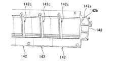
具体的には、放熱フィン14は、ヒートパイプ13の突出部131を両側から挟む第1放熱部141と第2放熱部142によって構成されている。第1放熱部141は、基部141aと、基部141aに対して垂直に連結されたフィン部141bとを有し、ヒートパイプ13の突出部131に対して筐体12の表面、即ち画像表示システムの表面101側に配置されている。
第2放熱部142は、基部142aと、基部142aに対して垂直に連結されたフィン部142bとを有し、ヒートパイプ13の突出部131に対して筐体12の背面、即ち画像表示システムの背面102側に配置されている。
Specifically, the heat radiating fin 14 is configured by a first heat radiating portion 141 and a second heat radiating portion 142 that sandwich the protruding portion 131 of the heat pipe 13 from both sides. The first heat radiating portion 141 has a base portion 141a and a fin portion 141b connected perpendicularly to the base portion 141a, and the surface of the housing 12, that is, the surface of the image display system with respect to the protruding portion 131 of the heat pipe 13. It is arranged on the surface 101 side.
The second heat radiating part 142 has a base part 142a and a fin part 142b connected perpendicularly to the base part 142a. The second heat radiating part 142 has a rear surface of the housing 12, that is, a part of the image display system. It is arranged on the back 102 side.

そして、第1放熱部141と第2放熱部142のそれぞれには、図17及び図18に示される様に、基部141a,142aに一対の溝141c,142cが形成されている。第1放熱部141と第2放熱部142によってヒートパイプ13の突出部131を両側から挟んだとき、該一対の溝141c,142cに該突出部131が嵌合する。
より具体的には、一対の溝141c,142cは半円筒状に形成されており、第1放熱部141と第2放熱部142によってヒートパイプ13の突出部131を両側から挟んだとき、一対の溝141c,142cによって円筒状の穴が形成され、ヒートパイプ13の突出部131は該円筒状の穴に嵌合する。
In each of the first heat radiation part 141 and the second heat radiation part 142, as shown in FIGS. 17 and 18, a pair of grooves 141c and 142c are formed in the base parts 141a and 142a. When the protruding portion 131 of the heat pipe 13 is sandwiched from both sides by the first heat radiating portion 141 and the second heat radiating portion 142, the protruding portion 131 is fitted into the pair of grooves 141c and 142c.
More specifically, the pair of grooves 141c and 142c are formed in a semi-cylindrical shape, and when the protruding portion 131 of the heat pipe 13 is sandwiched from both sides by the first heat radiating portion 141 and the second heat radiating portion 142, a pair of grooves 141c and 142c are formed. A cylindrical hole is formed by the grooves 141c and 142c, and the protrusion 131 of the heat pipe 13 is fitted into the cylindrical hole.

本実施の形態では、画像表示パネル11の背面111に、複数のヒートパイプ13が略鉛直方向に並んで配備されると共に(図4参照)、通気路122の内部には、複数のヒートパイプ13のそれぞれに対応する複数の放熱フィン14が略鉛直方向に配備されている。
そして、図17及び図18に示される様に、複数のヒートパイプ13のそれぞれに対応する複数の第1放熱部141が一体に形成されると共に、該複数のヒートパイプ13のそれぞれに対応する複数の第2放熱部142も一体に形成されている。
In the present embodiment, a plurality of heat pipes 13 are arranged in a substantially vertical direction on the back surface 111 of the image display panel 11 (see FIG. 4), and a plurality of heat pipes 13 are disposed inside the air passage 122. A plurality of radiating fins 14 corresponding to each of the above are arranged in a substantially vertical direction.
As shown in FIGS. 17 and 18, a plurality of first heat radiating portions 141 corresponding to each of the plurality of heat pipes 13 are integrally formed, and a plurality of corresponding to each of the plurality of heat pipes 13 are formed. The second heat radiating portion 142 is also integrally formed.

通気路122の内部に配備された上記放熱フィン14と同様に、通気路123の内部にも放熱フィン14が配備されている(例えば図4参照)。   Similarly to the heat radiating fins 14 provided inside the air passage 122, the heat radiating fins 14 are also provided inside the air passage 123 (see, for example, FIG. 4).

上記放熱フィン14によれば、ヒートパイプ13から通気路122,123の内部への放熱効率が高まり、その結果、画像表示装置1の冷却効率が高まることとなる。   According to the heat radiating fin 14, the heat radiating efficiency from the heat pipe 13 to the inside of the air passages 122 and 123 is increased, and as a result, the cooling efficiency of the image display device 1 is increased.

本実施の形態においては、放熱フィン14が第1放熱部141と第2放熱部142によって構成され、第1放熱部141と第2放熱部142には一対の溝141c,142cが形成されているので、第1放熱部141と第2放熱部142によってヒートパイプ13を両側から挟み、そして該ヒートパイプ13を一対の溝141c,142cに嵌合するだけで、放熱フィン14を形成しながら該放熱フィン14をヒートパイプ13に接続することが出来る。よって、ヒートパイプ13への放熱フィン14の接続が容易である。   In the present embodiment, the heat radiating fin 14 is constituted by the first heat radiating portion 141 and the second heat radiating portion 142, and a pair of grooves 141 c and 142 c are formed in the first heat radiating portion 141 and the second heat radiating portion 142. Therefore, the heat radiating fin 14 is formed while the heat pipe 13 is sandwiched from both sides by the first heat radiating portion 141 and the second heat radiating portion 142, and the heat pipe 13 is fitted into the pair of grooves 141c and 142c. The fin 14 can be connected to the heat pipe 13. Therefore, it is easy to connect the radiating fins 14 to the heat pipe 13.

又、本実施の形態においては、複数のヒートパイプ13のそれぞれに対応する複数の第1放熱部141が一体に形成されると共に、該複数のヒートパイプ13のそれぞれに対応する複数の第2放熱部142も一体に形成されているので、複数のヒートパイプ13を第1放熱部141と第2放熱部142で挟むという一回の作業で、該複数のヒートパイプ13の全てに放熱フィン14を取り付けることが出来る。その結果、複数のヒートパイプ13への放熱フィン14の取付けが簡略化されることとなる。   In the present embodiment, a plurality of first heat radiation portions 141 corresponding to each of the plurality of heat pipes 13 are integrally formed, and a plurality of second heat radiation corresponding to each of the plurality of heat pipes 13 is formed. Since the part 142 is also integrally formed, the heat radiation fins 14 are attached to all of the plurality of heat pipes 13 in a single operation of sandwiching the plurality of heat pipes 13 between the first heat radiation part 141 and the second heat radiation part 142. Can be attached. As a result, the attachment of the radiation fins 14 to the plurality of heat pipes 13 is simplified.

本実施の形態では、図17に示される様に第1放熱部141において、複数のフィン部141bが基部141aに垂直に連結されており、複数のフィン部141bの間に隙間が形成されている。第2放熱部142においても同様である。そして、通気路122,123内を流れる空気は、上記隙間を通って流れる。   In the present embodiment, as shown in FIG. 17, in the first heat radiating portion 141, the plurality of fin portions 141b are vertically connected to the base portion 141a, and gaps are formed between the plurality of fin portions 141b. . The same applies to the second heat radiation part 142. And the air which flows through the ventilation paths 122 and 123 flows through the said clearance gap.

尚、図17では第1放熱部141において、複数のフィン部141bの先端が、連結部143によって互いに連結されており、上記隙間はフィン部141b、基端部141a及び連結部143によって囲まれている。第2放熱部142においても同様である。この場合、通気路122,123内の空気を該隙間だけに通すことによって、放熱フィン14を、ダクトとしても機能するダクトフィンとすることが出来る。もちろん、隙間及び該隙間の外側の両方に、通気路122,123内の空気を流してもよい。   In FIG. 17, in the first heat radiating portion 141, the tips of the plurality of fin portions 141b are connected to each other by the connecting portion 143, and the gap is surrounded by the fin portion 141b, the base end portion 141a, and the connecting portion 143. Yes. The same applies to the second heat radiation part 142. In this case, the heat radiating fin 14 can be a duct fin that also functions as a duct by allowing the air in the air passages 122 and 123 to pass through only the gap. Of course, you may flow the air in the ventilation paths 122 and 123 to both a clearance and the outer side of this clearance.

本実施の形態では、ヒートパイプ13から通気路122,123の内部への放熱効率を高めるための放熱部材として、放熱フィン14を用いたが、放熱フィン14に替えて他の放熱部材を採用してもよい。   In the present embodiment, the heat radiating member 14 is used as a heat radiating member for improving the heat radiating efficiency from the heat pipe 13 to the inside of the air passages 122 and 123, but another heat radiating member is used instead of the heat radiating fin 14. May be.

<通気用ファン15,16>
通気用ファン15,16は、図4に示される様に通気路122の内部に配備されており、通気用ファン15は、通気路122の上端部122aに配置され、通気用ファン16は、通気路122の下端部122bに配置されている。
<Ventilation fans 15 and 16>
As shown in FIG. 4, the ventilation fans 15 and 16 are disposed inside the ventilation path 122, the ventilation fan 15 is disposed at the upper end 122 a of the ventilation path 122, and the ventilation fan 16 is disposed in the ventilation path 122. It is arranged at the lower end 122 b of the path 122.

通気用ファン15,16は、通気路122内の空気を通気路122に沿って同じ方向に流す。具体的には通気用ファン15は、図6に示される様に、通気路122内の空気を通気口62から筺体12の外部へ排出することにより、通気路122内の空気を略鉛直方向において下から上に流す。通気用ファン16は、図7に示される様に、筺体12の外部の空気を通気口61から通気路122の内部へ吸入することにより、通気路122内の空気を略鉛直方向において下から上に流す。尚、図6及び図7では、空気の流れが実線矢印によって示されている。   The ventilation fans 15 and 16 allow the air in the ventilation path 122 to flow in the same direction along the ventilation path 122. Specifically, as shown in FIG. 6, the ventilation fan 15 discharges the air in the ventilation path 122 from the ventilation hole 62 to the outside of the housing 12, thereby causing the air in the ventilation path 122 to flow in a substantially vertical direction. Run from bottom to top. As shown in FIG. 7, the ventilation fan 16 sucks air outside the housing 12 from the ventilation openings 61 into the ventilation path 122, so that the air in the ventilation path 122 is lifted from below in a substantially vertical direction. Shed. In FIGS. 6 and 7, the air flow is indicated by solid arrows.

通気路123の内部にも、通気路122と同様に、通気用ファン15,16が配備されており(図4参照)、通気用ファン15,16によって、通気路123内の空気が略鉛直方向において下から上に流される。   The ventilation fans 15 and 16 are also provided inside the ventilation path 123 in the same manner as the ventilation path 122 (see FIG. 4), and the ventilation fans 15 and 16 allow the air in the ventilation path 123 to move in a substantially vertical direction. At the bottom.

上記通気用ファン15,16によれば、ヒートパイプ13から通気路122,123の内部に放出された熱を、筐体12の外部に効率良く発散することが出来る。よって、通気路122の内部においてヒートパイプ13及び放熱フィン14の放熱効率が高まる。   According to the ventilation fans 15 and 16, the heat released from the heat pipe 13 into the ventilation paths 122 and 123 can be efficiently dissipated to the outside of the housing 12. Therefore, the heat radiation efficiency of the heat pipe 13 and the heat radiation fin 14 is increased inside the air passage 122.

そして、本実施の形態においては、通気路122,123内の空気が下から上に流れるので、通気路122,123内に放出された熱によって温まった空気は上昇するという空気の性質と相俟って、通気路122,123内の空気は効率良く下から上に流れることとなる。よって、通気路122,123内に放出された熱を効率良く筐体12の外部に発散することが出来る。   In the present embodiment, since the air in the air passages 122 and 123 flows from the bottom to the top, the air warmed by the heat released into the air passages 122 and 123 rises. Thus, the air in the air passages 122 and 123 efficiently flows from the bottom to the top. Therefore, the heat released into the air passages 122 and 123 can be efficiently dissipated outside the housing 12.

本実施の形態では、通気路122,123内の空気を筐体12の外部に排出する送風手段として、通気用ファン15,16を用いたが、通気用ファン15,16に替えて他の送風手段を採用してもよい。   In the present embodiment, the ventilation fans 15 and 16 are used as the blowing means for discharging the air in the ventilation paths 122 and 123 to the outside of the housing 12, but other ventilation is used instead of the ventilation fans 15 and 16. Means may be employed.

<集熱フィン17>
集熱フィン17は、図4に示されるように、収容室121の内部において複数のヒートパイプ13に跨って接続されている。具体的には集熱フィン17は、図9に示されるように、基部171とフィン部172とから構成されている。基部171は、複数のヒートパイプ13に跨って延びると共に、該複数のヒートパイプ13に接触している。フィン部172は、基部171の表面に垂直に連結され、基部171の長手方向に基部171の一端から他端まで延びている。
<Heat collecting fins 17>
As shown in FIG. 4, the heat collection fins 17 are connected across the plurality of heat pipes 13 inside the accommodation chamber 121. Specifically, as shown in FIG. 9, the heat collecting fins 17 include a base portion 171 and a fin portion 172. The base 171 extends across the plurality of heat pipes 13 and is in contact with the plurality of heat pipes 13. The fin portion 172 is vertically connected to the surface of the base portion 171 and extends from one end of the base portion 171 to the other end in the longitudinal direction of the base portion 171.

上記集熱フィン17によれば、画像表示パネル11から循環流路92内に放たれた熱を、効率良く回収してヒートパイプ13に導くことが出来る。これにより、熱交換手段としてのヒートパイプ13の機能が高まり、その結果、画像表示装置1の冷却効率が高まることとなる。   According to the heat collection fin 17, the heat released from the image display panel 11 into the circulation flow path 92 can be efficiently recovered and guided to the heat pipe 13. Thereby, the function of the heat pipe 13 as a heat exchange means increases, and as a result, the cooling efficiency of the image display apparatus 1 increases.

尚、図4は、集熱フィン17が、中心線111aに対して通気路122側のヒートパイプ13にのみ接続されている状態を示しているが、実際は、通気路123側のヒートパイプ13にも集熱フィン17が接続されている。   4 shows a state in which the heat collecting fins 17 are connected only to the heat pipe 13 on the air passage 122 side with respect to the center line 111a, but in actuality, the heat collecting fin 17 is connected to the heat pipe 13 on the air passage 123 side. Also, the heat collecting fins 17 are connected.

本実施の形態では、循環流路92内を流れる空気から集熱する集熱部材として、集熱フィン17を用いたが、集熱フィン17に替えて他の集熱部材を採用してもよい。   In the present embodiment, the heat collecting fins 17 are used as the heat collecting members that collect heat from the air flowing in the circulation flow path 92, but other heat collecting members may be employed instead of the heat collecting fins 17. .

<断熱部材7>
断熱部材7は、図14に示される様に、蒸発器191と画像表示パネル11との間に介在している。具体的には、蒸発器191は、画像表示パネル11の背面111側に配置されており、断熱部材7は、画像表示パネル11の背面111と蒸発器191の前面191aとの間に配置されている。断熱部材7の材質には、例えばウレタンやシリコン系のゴムなどが用いられる。
<Insulation member 7>
As shown in FIG. 14, the heat insulating member 7 is interposed between the evaporator 191 and the image display panel 11. Specifically, the evaporator 191 is disposed on the back surface 111 side of the image display panel 11, and the heat insulating member 7 is disposed between the back surface 111 of the image display panel 11 and the front surface 191 a of the evaporator 191. Yes. As the material of the heat insulating member 7, for example, urethane or silicon rubber is used.

上述したように、画像表示パネル11で発生した熱は、循環流路92内を流れる空気を媒体として蒸発器191に導かれ、そして蒸発器191によって回収される。上記断熱部材7によれば、蒸発器191によって熱を回収する過程で、画像表示パネル11のうち蒸発器191の近傍位置の部分が過剰に冷えてしまうことを防止することが出来る。よって、画像表示パネル11の温度分布が均一となり、その結果、画像表示パネル11の機能は良好な状態に維持されることとなる。   As described above, the heat generated in the image display panel 11 is guided to the evaporator 191 by using the air flowing in the circulation channel 92 as a medium, and is recovered by the evaporator 191. According to the heat insulating member 7, it is possible to prevent the portion of the image display panel 11 in the vicinity of the evaporator 191 from being excessively cooled in the process of recovering heat by the evaporator 191. Therefore, the temperature distribution of the image display panel 11 becomes uniform, and as a result, the function of the image display panel 11 is maintained in a good state.

<回路基板用の集熱フィン71と送風ファン72>
回路基板用の集熱フィン71は、図14及び図20に示される様に、背面壁125の背面のうち蒸発器191の背面側の領域、即ち背面壁125の下端近傍の領域に配置されている。これにより、集熱フィン71は、収容室121を形成する背面壁125のうち蒸発器191によって冷却される領域(冷却領域)に配置されることとなる。該集熱フィン71は、集熱手段として機能し、背面壁125の背面上に存在する空気から熱を集める。
<Heat collecting fins 71 and blower fans 72 for circuit boards>
As shown in FIGS. 14 and 20, the heat collecting fins 71 for the circuit board are arranged in a region on the back side of the evaporator 191 in the back surface of the back wall 125, that is, a region near the lower end of the back wall 125. Yes. As a result, the heat collecting fins 71 are arranged in a region (cooling region) cooled by the evaporator 191 in the back wall 125 forming the accommodation chamber 121. The heat collecting fins 71 function as heat collecting means and collect heat from the air existing on the back surface of the back wall 125.

又、回路基板用の送風ファン72は、図14及び図20に示される様に、回路基板用の集熱フィン71の上方近傍の位置にて背面壁125の背面に配置されている。該送風ファン72は、送風手段として機能し、背面壁125の冷却領域の背面側に存在する空気を、背面壁125の背面に沿って流す。本実施の形態では、図20において矢印D1で示される様に、背面壁125の冷却領域の背面側に存在する空気が、送風ファン72によって回路基板11eへ送り込まれる。   Further, as shown in FIGS. 14 and 20, the blower fan 72 for the circuit board is disposed on the back surface of the back wall 125 at a position near the upper side of the heat collecting fins 71 for the circuit board. The blower fan 72 functions as a blower, and causes air existing on the back side of the cooling region of the back wall 125 to flow along the back surface of the back wall 125. In the present embodiment, as indicated by an arrow D1 in FIG. 20, the air present on the back side of the cooling region of the back wall 125 is sent to the circuit board 11e by the blower fan 72.

上述した回路基板用の集熱フィン71によれば、背面壁125の冷却領域の背面側に存在する空気から熱を集め、集めた熱を蒸発器191によって回収することが出来る。よって、背面壁125の冷却領域の背面側に存在する空気が、蒸発器191によって効率良く冷却されることとなる。   According to the heat collecting fins 71 for the circuit board described above, heat can be collected from the air existing on the back side of the cooling region of the back wall 125, and the collected heat can be recovered by the evaporator 191. Therefore, the air existing on the back side of the cooling region of the back wall 125 is efficiently cooled by the evaporator 191.

そして、冷却された空気は、回路基板用の送風ファン72によって、背面壁125の背面に配備されている回路基板11eに送り込まれ、該空気によって、回路基板11eで発生した熱が回収されることとなる。その結果、回路基板11eが効率良く冷却されることとなる。   The cooled air is sent to the circuit board 11e disposed on the back surface of the back wall 125 by the blower fan 72 for the circuit board, and the heat generated in the circuit board 11e is recovered by the air. It becomes. As a result, the circuit board 11e is efficiently cooled.

本実施の形態では、回路基板11eを効率良く冷却するための集熱手段及び送風手段として、回路基板用の集熱フィン71及び送風ファン72を用いたが、これらに替えて他の集熱手段及び送風手段を採用してもよい。又、本実施の形態では、背面壁125の冷却領域の背面側に存在する空気を、送風ファン72によって回路基板11eへ送り込んだが(図20参照)、例えば回路基板11e近傍の空気を、送風ファン72によって集熱フィン71に送り込んでもよい。   In the present embodiment, the heat collecting fins 71 and the blower fan 72 for the circuit board are used as the heat collecting means and the air blowing means for efficiently cooling the circuit board 11e, but instead of these, other heat collecting means. Further, air blowing means may be employed. In the present embodiment, air existing on the back side of the cooling region of the back wall 125 is sent to the circuit board 11e by the blower fan 72 (see FIG. 20). For example, air near the circuit board 11e is sent to the blower fan. 72 may be sent to the heat collecting fins 71.

更には、集熱フィン71を、蒸発器191の上方の位置であって、且つ送風ファン72の下方の位置に配置してもよい。これにより、集熱フィン71は、蒸発器191によって生成された冷気を放出するフィンとして機能することとなる。   Furthermore, the heat collection fins 71 may be disposed at a position above the evaporator 191 and below the blower fan 72. As a result, the heat collection fins 71 function as fins that discharge the cold air generated by the evaporator 191.

3.画像表示装置を支持台に取り付けるための構成について
図21に示される様に、画像表示装置1の背面には、該背面から突出した棒状の係合部材81が取り付けられ、係合部材81の先端には、画像表示装置1の背面からの突出量を大きくするための延長部材811が着脱可能に取り付けられている。具体的には、係合部材81の先端部には雌ねじが形成される一方、延長部材811の基端部には雄ねじが形成されており、該雄ねじを雌ねじにねじ込むことによって延長部材811が係合部材81の先端に取り付けられる(図24参照)。
本実施の形態では、4つの係合部材81が画像表示装置1の背面に配備されており、それらの係合部材81は、該背面の両側端縁に沿って上下に1つずつ取り付けられている。
3. As shown in FIG. 21, a rod-like engagement member 81 protruding from the rear surface is attached to the rear surface of the image display device 1, and the tip of the engagement member 81 is attached. Is attached detachably with an extending member 811 for increasing the amount of protrusion from the back surface of the image display device 1. Specifically, a female screw is formed at the distal end of the engaging member 81, while a male screw is formed at the proximal end of the extension member 811, and the extension member 811 is engaged by screwing the male screw into the female screw. It attaches to the front-end | tip of the joining member 81 (refer FIG. 24).
In the present embodiment, four engagement members 81 are arranged on the back surface of the image display device 1, and the engagement members 81 are attached one by one up and down along both side edges of the back surface. Yes.

又、図22に示される様に、フレーム部21を構成する一対の側壁フレーム部211,211には、その内周面に、リング状の被係合部材82がゴム状の弾性部材84を介して取り付けられている。ここで、被係合部材82は、画像表示装置1に取り付けられている係合部材81が係合されるものである。
本実施の形態では、図22に示される様に、画像表示装置1に取り付けられている4つの係合部材81のそれぞれに対応して、4つの被係合部材82が側壁フレーム211,211に取り付けられている。
Further, as shown in FIG. 22, a pair of side wall frame portions 211, 211 constituting the frame portion 21 has a ring-shaped engaged member 82 on its inner peripheral surface via a rubber-like elastic member 84. Attached. Here, the engaged member 82 is engaged with the engaging member 81 attached to the image display device 1.
In the present embodiment, as shown in FIG. 22, four engaged members 82 correspond to each of the four engaging members 81 attached to the image display device 1 to the side wall frames 211, 211. It is attached.

画像表示装置1を支持台2に取り付ける場合、図21及び図23に示される様に、係合部材81に取り付けられている延長部材811を、その先端から、該係合部材81に対応する被係合部材82に挿入する。そして、画像表示装置1をフレーム部21の方へ押し込む。   When the image display device 1 is attached to the support 2, as shown in FIGS. 21 and 23, the extension member 811 attached to the engagement member 81 is attached from the tip thereof to the cover corresponding to the engagement member 81. Insert into the engaging member 82. Then, the image display device 1 is pushed toward the frame portion 21.

これにより、係合部材81は、延長部材811によって被係合部材82まで案内され、係合部材81は被係合部材82に嵌挿される。その結果、係合部材81と被係合部82とは、画像表示装置1をフレーム部21に嵌め込んだ嵌め込み状態において互いに係合することとなる。このように、延長部材811は、被係合部材82への係合部材81の嵌挿を補助するものである。   As a result, the engaging member 81 is guided to the engaged member 82 by the extending member 811, and the engaging member 81 is inserted into the engaged member 82. As a result, the engaging member 81 and the engaged portion 82 are engaged with each other in the fitted state in which the image display device 1 is fitted into the frame portion 21. Thus, the extension member 811 assists the insertion of the engagement member 81 into the engaged member 82.

係合部材81を被係合部材82に嵌挿した後、図24に示される様に、延長部材811を取り外す。そして、図25に示される様に、被係合部材82に嵌挿された係合部材81の先端部に、係合保持部材83を着脱可能に取り付ける。具体的には、係合保持部材83には雄ねじが形成されており、該雄ねじを係合部材81に形成されている雌ねじにねじ込むことによって、係合保持部材83を係合部材81の先端に取り付ける。   After the engaging member 81 is inserted into the engaged member 82, the extension member 811 is removed as shown in FIG. Then, as shown in FIG. 25, the engagement holding member 83 is detachably attached to the distal end portion of the engagement member 81 inserted into the engaged member 82. Specifically, the engagement holding member 83 is formed with a male screw, and by screwing the male screw into a female screw formed on the engagement member 81, the engagement holding member 83 is attached to the tip of the engagement member 81. Install.

係合保持部材83を係合部材81の先端に取り付けた取付け状態においては、被係合保持部材83は、被係合保持部材82の開口端面82aに当接する。これにより、係合部材81と被係合部材82との係合が、係合保持部材83によって保持されることとなる。   In the attached state in which the engagement holding member 83 is attached to the distal end of the engagement member 81, the engaged holding member 83 abuts on the open end surface 82 a of the engaged holding member 82. As a result, the engagement between the engagement member 81 and the engaged member 82 is held by the engagement holding member 83.

上記構成によれば、係合部材81と被係合部材82とを係合するだけで、嵌め込み状態での画像表示装置1の位置が決まるので、取付け時の画像表示装置1の位置決めを簡略化することが出来る。しかも、係合部材81と被係合部材82との係合を係合保持部材83によって保持することにより、画像表示装置1は、支持台2に固定されることとなる。   According to the above configuration, the position of the image display device 1 in the fitted state is determined simply by engaging the engaging member 81 and the engaged member 82, so that the positioning of the image display device 1 at the time of attachment is simplified. I can do it. In addition, the image display device 1 is fixed to the support base 2 by holding the engagement between the engagement member 81 and the engaged member 82 by the engagement holding member 83.

又、本実施の形態においては、被係合部材82が弾性部材84を介してフレーム部21に取り付けられているので、画像表示システムに振動が加えられた場合でも、該振動は弾性部材84によって吸収されることとなる。従って、フレーム部21から画像表示装置1に振動が伝達することを防止することが出来、その結果、振動による画像表示装置1の破損が防止されることとなる。   In the present embodiment, since the engaged member 82 is attached to the frame portion 21 via the elastic member 84, the vibration is caused by the elastic member 84 even when vibration is applied to the image display system. Will be absorbed. Therefore, it is possible to prevent vibration from being transmitted from the frame portion 21 to the image display apparatus 1, and as a result, damage to the image display apparatus 1 due to vibration is prevented.

4.照明器具の配置について
収容室121を形成する背面壁125は、図12に示される様に、鉛直壁部125aと、傾斜壁部125b,125cとを具えている。鉛直壁部125aは、画像表示パネル11の背面111に沿って拡がっている。傾斜壁部125bは、鉛直壁部125aの上端から背板3側に屈曲して斜め上方向に延びる一方、傾斜壁部125cは、鉛直壁部125aの下端から背板3側に屈曲して斜め下方向に延びている。
4). About Arrangement of Lighting Fixture As shown in FIG. 12, the back wall 125 forming the accommodation chamber 121 includes a vertical wall portion 125a and inclined wall portions 125b and 125c. The vertical wall portion 125 a extends along the back surface 111 of the image display panel 11. The inclined wall portion 125b is bent from the upper end of the vertical wall portion 125a to the back plate 3 side and extends obliquely upward, while the inclined wall portion 125c is bent and inclined from the lower end of the vertical wall portion 125a to the back plate 3 side. It extends downward.

これにより、背面壁125と画像表示パネル11の背面111との間に、傾斜壁部125b,125cの表面のそれぞれに沿う第1収容空間12b,12cが形成されることとなる。即ち、循環流路92の流路部11cの上端部と下端部のそれぞれに、第1収容空間12b,12cが形成されている。
又、背面壁125と背板3との間には、鉛直壁部125aの背面に沿う第2収容空間12aが形成されることとなる。
Thus, first housing spaces 12b and 12c are formed between the rear wall 125 and the rear surface 111 of the image display panel 11 along the surfaces of the inclined wall portions 125b and 125c, respectively. That is, the first accommodating spaces 12b and 12c are formed in the upper end portion and the lower end portion of the flow path portion 11c of the circulation flow path 92, respectively.
Moreover, between the back wall 125 and the backplate 3, the 2nd accommodation space 12a along the back surface of the vertical wall part 125a will be formed.

そして、一方の第1収容空間12bには、図12及び図13に示される様に、循環用ファン18が配置され、他方の第1収容空間12cには、図12及び図14に示される様に、循環用ファン181と蒸発器191が配置されている。
又、第2収容空間12aには、図12に示される様に、広告フィルムを照明するための照明器具5が配置されている。具体的には、照明器具5を構成する複数の蛍光灯が、第2収容空間12aの内部において、鉛直壁部125aに沿って水平方向に並んでいる。
Then, as shown in FIGS. 12 and 13, a circulation fan 18 is arranged in one first housing space 12b, and in the other first housing space 12c, as shown in FIGS. In addition, a circulation fan 181 and an evaporator 191 are arranged.
Further, as shown in FIG. 12, a lighting fixture 5 for illuminating the advertising film is disposed in the second accommodation space 12a. Specifically, the several fluorescent lamp which comprises the lighting fixture 5 is located in a line with the horizontal direction along the vertical wall part 125a inside the 2nd accommodation space 12a.

上述したように収容室121を形成する背面壁125に傾斜壁部125b,125cを設けることによって、循環用ファン18,181及び蒸発器191が配置される第1収容空間12b,12cが収容室121の内部に形成されると共に、照明器具5が配置される第2収容空間12aが、循環用ファン18のほぼ下方位置であって、且つ循環用ファン181及び蒸発器191のほぼ上方位置にて、収容室121の外側に形成される。即ち、第2収容空間12aは、鉛直方向又はほぼ鉛直方向において第1収容空間12b,12cの間に介在することとなる。
よって、循環用ファン18,181及び蒸発器191と、照明器具5とを鉛直方向又はほぼ鉛直方向に並べて配置することが可能となり、その結果、画像表示装置1が厚み方向に大型化することが回避される。
As described above, the inclined walls 125 b and 125 c are provided on the back wall 125 that forms the storage chamber 121, so that the first storage spaces 12 b and 12 c in which the circulation fans 18 and 181 and the evaporator 191 are arranged are stored in the storage chamber 121. And the second housing space 12a in which the lighting fixture 5 is disposed is substantially below the circulation fan 18 and substantially above the circulation fan 181 and the evaporator 191. It is formed outside the storage chamber 121. That is, the second storage space 12a is interposed between the first storage spaces 12b and 12c in the vertical direction or substantially vertical direction.
Therefore, the circulation fans 18 and 181 and the evaporator 191 and the lighting fixture 5 can be arranged side by side in the vertical direction or substantially vertical direction. As a result, the image display device 1 can be increased in size in the thickness direction. Avoided.

5.画像表示システムの設置状態について
上記画像表示システムは、図3に示される様に、交通機関の停留所に設置されるべき待合いユニット9に具えられる。待合いユニット9は、待合い空間91に面して設置されるべきフレーム体93を具え、該フレーム体93は、壁や屋根など待合い空間91を形成するフレーム部と、支持台2となる側壁フレーム部931とによって構成されている。
5. About the installation state of an image display system The said image display system is provided in the waiting unit 9 which should be installed in the stop of a transportation facility, as FIG. 3 shows. The waiting unit 9 includes a frame body 93 to be installed facing the waiting space 91, and the frame body 93 includes a frame portion that forms the waiting space 91 such as a wall or a roof, and a side wall frame portion that serves as the support base 2. 931.

停留所に設置された待合いユニット9において、画像表示装置1は、図3に示される様に、フレーム体93、即ち支持台2となる側壁フレーム部931に取り付けられており、画像表示パネル11の表示画面112aを待合い空間91に向けて設置されている。   In the waiting unit 9 installed at the stop, the image display device 1 is attached to the frame body 93, that is, the side wall frame portion 931 serving as the support base 2, as shown in FIG. The screen 112a is installed toward the waiting space 91.

上記待合いユニット9によれば、画像表示装置1は、画像表示パネル11の表示画面112aが待合い空間91に向けて設置されているので、待合いユニット9が設置された停留所で待機している利用者に対して、種々の情報を動画や静止画によって提供することが出来る。又、待合い空間91に面してフレーム体93が設置されているので、停留所の近辺を通行する車両の運転者には画像表示パネル11の表示画面112aが見えにくい。よって、運転者の注意が表示画面112aに映し出された画像に向きにくく、その結果、事故等を招く危険性が低減されることとなる。   According to the waiting unit 9, since the display screen 112a of the image display panel 11 is installed toward the waiting space 91, the image display device 1 is a user waiting at the stop where the waiting unit 9 is installed. On the other hand, various information can be provided by moving images or still images. Further, since the frame body 93 is installed facing the waiting space 91, the display screen 112a of the image display panel 11 is difficult to see for the driver of the vehicle passing in the vicinity of the stop. Therefore, it is difficult for the driver's attention to be directed to the image displayed on the display screen 112a, and as a result, the risk of causing an accident or the like is reduced.

図3に示される様に停留所が、交通機関の進行方向941が一方向に規定された通路94に沿って設けられている場合には、図3に示される様に、フレーム体93の側壁フレーム部931を、通路94から待合い空間91に向かって進行方向941とは逆側に設置し、画像表示装置1を、進行方向941に向けて側壁フレーム931に取り付けることが好ましい。   As shown in FIG. 3, when the stop is provided along a passage 94 in which the traveling direction 941 of the transportation system is defined in one direction, as shown in FIG. It is preferable that the portion 931 is installed on the side opposite to the traveling direction 941 from the passage 94 toward the waiting space 91, and the image display device 1 is attached to the side wall frame 931 toward the traveling direction 941.

尚、図3に示される待合いユニット9は、例えば通路が対向する2車線から成る場合であって交通機関が右側通行である場合において、片方の車線に沿って設けられた形態のものであり、例えば交通機関が左側通行である場合においては、待合いユニットは、図3に示される待合いユニット9を左右逆転させた形態のものとなる。   In addition, the waiting unit 9 shown in FIG. 3 is of a form provided along one lane, for example, when the passage is composed of two lanes facing each other and the transportation is right-hand traffic. For example, when the transportation is left-hand traffic, the waiting unit has a form in which the waiting unit 9 shown in FIG.

これにより、車両の運転者から画像表示パネル11の表示画面112aが見えなくなるので、運転者の注意が表示画面112aに映し出された画像に向くことがなくなる。よって、事故等を招く危険性がより低減される。   As a result, the display screen 112a of the image display panel 11 cannot be seen from the driver of the vehicle, so that the driver's attention is not directed to the image displayed on the display screen 112a. Therefore, the risk of causing an accident or the like is further reduced.

上述したように画像表示装置1が待合い空間91に向けて設置されることによって、背面102、具体的には背板3が、待合い空間91の外側に向くこととなる。よって、背板3に広告フィルムを貼付することにより、待合いユニット9が設置された停留所の外側を通行する者又は運転者に対しても、種々の情報を提供することが出来る。尚、広告フィルムであれば、それが運転者から見えたとしても事故等を招く危険性は低い。   As described above, when the image display device 1 is installed toward the waiting space 91, the back surface 102, specifically, the back plate 3, faces the outside of the waiting space 91. Therefore, by sticking an advertising film to the back plate 3, various information can be provided to a person or a driver who passes outside the stop where the waiting unit 9 is installed. In the case of an advertising film, even if it is visible to the driver, the risk of causing an accident or the like is low.

上述したように画像表示装置1を、画像表示パネル11の表示画面112aを待合い空間91に向けて設置する場合、空気調和機19によって回収した熱は、図3において矢印Dで示される様に、画像表示システムの背面102から待合い空間91の外側に向けて放出されることが好ましい。
これにより、待合いユニット9が設置された停留所に待機している利用者に熱風が掛かることがなくなる。従って、利用者に不快感を与えることがない。
As described above, when the image display device 1 is installed with the display screen 112a of the image display panel 11 facing the waiting space 91, the heat recovered by the air conditioner 19 is indicated by an arrow D in FIG. It is preferable that the light is emitted from the back surface 102 of the image display system toward the outside of the waiting space 91.
As a result, hot air is not applied to the user waiting at the stop where the waiting unit 9 is installed. Therefore, there is no discomfort to the user.

6.変形例
6−1.変形例1
上述した画像表示装置1では、複数のヒートパイプ13は略鉛直方向へ所定間隔で繰り返し配列されているが(図4参照)が、これに限らず他の態様であってもよい。例えば、異なる間隔でヒートパイプ13を配列してもよい。
但し、画像表示装置1の冷却効率を高めるという観点からは、上述した画像表示装置1のように画像表示パネル11の背面111全体に亘ってヒートパイプ13が配設されることが好ましい。これにより、画像表示パネル11の背面111全体から熱を回収することが可能になる。
6). Modification 6-1. Modification 1
In the image display device 1 described above, the plurality of heat pipes 13 are repeatedly arranged at a predetermined interval in the substantially vertical direction (see FIG. 4). For example, the heat pipes 13 may be arranged at different intervals.
However, from the viewpoint of increasing the cooling efficiency of the image display device 1, it is preferable that the heat pipe 13 is disposed over the entire back surface 111 of the image display panel 11 as in the image display device 1 described above. This makes it possible to recover heat from the entire back surface 111 of the image display panel 11.

6−2.変形例2
上述した画像表示装置1では、通気路122,123内の空気を、通気用ファン15,16によって下から上に向かって流しているが、上から下に向かって流してもよい。例えば、画像表示装置1を搭載した画像表示システムの設置場所における環境等を考慮した場合、通気路122,123内の空気を上から下に流した方がよいことがある。
6-2. Modification 2
In the image display device 1 described above, the air in the air passages 122 and 123 is caused to flow from the bottom to the top by the ventilation fans 15 and 16, but may be flowed from the top to the bottom. For example, when the environment at the installation location of the image display system on which the image display device 1 is mounted is taken into consideration, it may be better to flow the air in the air passages 122 and 123 from the top to the bottom.

又、上述した画像表示装置1では、通気路122,123に、通気用ファンが2つずつ配備されているが、通気路122,123に配備する通気用ファンの数は、1つでもよいし、3つ以上であってもよい。   In the image display device 1 described above, two ventilation fans are provided in the ventilation paths 122 and 123, but the number of ventilation fans provided in the ventilation paths 122 and 123 may be one. Three or more may be sufficient.

更に、上述した画像表示装置1では、通気用ファン15を通気路122,123の上端部122a,123aに配置し、通気用ファン16を通気路122,123の下端部122b,123bに配置しているが、これに限らず他の位置に配置してもよい。但し、通気路122,123内の空気を筐体12の外部に排出することが可能な配置にする必要がある。   Further, in the image display device 1 described above, the ventilation fan 15 is arranged at the upper end portions 122 a and 123 a of the ventilation paths 122 and 123, and the ventilation fan 16 is arranged at the lower ends 122 b and 123 b of the ventilation paths 122 and 123. However, the present invention is not limited to this and may be arranged at other positions. However, it is necessary to arrange the air in the ventilation paths 122 and 123 so that the air can be discharged to the outside of the housing 12.

6−3.変形例3
上述した画像表示装置1では、循環流路92は、表面112に沿う流路部11a、上端面113に沿う流路部11b、背面111に沿う流路部11c、及び下端面114に沿う流路部11dから構成されているが、収容室121の内部において画像表示パネル11を包囲する他の経路を循環流路92としてもよい。
例えば、画像表示パネル11の側面と、収容室121を形成する側面壁121a,121bとの間に流路部を形成し、該流路部と流路部11a,11cとによって循環流路92を形成してもよい。
6-3. Modification 3
In the image display device 1 described above, the circulation flow path 92 includes the flow path portion 11a along the surface 112, the flow path portion 11b along the upper end surface 113, the flow path portion 11c along the back surface 111, and the flow path along the lower end surface 114. Although it is configured from the portion 11 d, another path surrounding the image display panel 11 inside the storage chamber 121 may be used as the circulation flow path 92.
For example, a channel portion is formed between the side surface of the image display panel 11 and the side walls 121a and 121b forming the storage chamber 121, and the circulation channel 92 is defined by the channel portion and the channel portions 11a and 11c. It may be formed.

又、上述した画像表示装置1では、循環用ファン18によって、表面112に沿う流路部11a内の空気を下から上に向かって流しているが、上から下に向かって流してもよい。この場合、循環用ファン18は、画像表示パネル11の下端面114近傍の位置に設置することが好ましい。尚、循環用ファン18の位置は、画像表示パネル11の上端面113または下端面114近傍の位置に限定されるものではなく、他の位置であってもよい。   Further, in the image display device 1 described above, the air in the flow path portion 11a along the surface 112 is caused to flow from the bottom to the top by the circulation fan 18, but the air may flow from the top to the bottom. In this case, the circulation fan 18 is preferably installed at a position near the lower end surface 114 of the image display panel 11. Note that the position of the circulation fan 18 is not limited to the position in the vicinity of the upper end surface 113 or the lower end surface 114 of the image display panel 11, and may be another position.

6−4.変形例4
上述した画像表示装置1では、循環用ファン181は、循環流路92の流路部11cの下端部において蒸発器191の上方位置に配置されているが、循環用ファン181を、蒸発器191の下方位置に配置してもよい。
6-4. Modification 4
In the image display device 1 described above, the circulation fan 181 is disposed above the evaporator 191 at the lower end of the flow path portion 11 c of the circulation flow path 92, but the circulation fan 181 is connected to the evaporator 191. You may arrange | position in a downward position.

かかる態様によれば、循環用ファン181は蒸発器191から空気を吸い込むので、蒸発器191に対して上方から空気が送り込まれることとなる。よって、かかる態様でも、蒸発器191によって熱を効率良く回収することが出来る。   According to this aspect, since the circulation fan 181 sucks air from the evaporator 191, air is sent into the evaporator 191 from above. Therefore, also in this aspect, heat can be efficiently recovered by the evaporator 191.

6−5.変形例5
上述した画像表示装置1では、通気路122の内部に配備されている放熱フィン14を第1放熱部141と第2放熱部142によって構成し、ヒートパイプ13の突出部131を一対の溝141c,142cに嵌合させた状態で、第1放熱部141と第2放熱部142によって突出部131を両側から挟んでいたが、例えば、放熱フィン14を第1放熱部141のみで構成し、第1放熱部141に形成されている溝141cにヒートパイプ13の突出部131を嵌合させることによって、放熱フィン14をヒートパイプ13の突出部131に取り付けてもよい。
6-5. Modification 5
In the image display device 1 described above, the heat radiating fins 14 disposed in the air passage 122 are configured by the first heat radiating portion 141 and the second heat radiating portion 142, and the protruding portion 131 of the heat pipe 13 is formed as a pair of grooves 141 c, While the protrusion 131 is sandwiched from both sides by the first heat radiating portion 141 and the second heat radiating portion 142 in a state of being fitted to 142 c, for example, the heat radiating fin 14 is configured only by the first heat radiating portion 141, The heat dissipating fins 14 may be attached to the protrusions 131 of the heat pipe 13 by fitting the protrusions 131 of the heat pipe 13 into the grooves 141 c formed in the heat dissipation part 141.

かかる態様によれば、ヒートパイプ13への放熱フィン14の取付けを簡略化することが出来る。   According to this aspect, the attachment of the radiation fins 14 to the heat pipe 13 can be simplified.

6−6.変形例6
上述した画像表示装置1では、集熱フィン17が、収容室121の内部において複数のヒートパイプ13に跨って接続されていたが、これに限られるものでない。例えば、図26に示される様に、集熱フィン17を配備せずに画像表示装置1を構成してもよい。
6-6. Modification 6
In the image display device 1 described above, the heat collection fins 17 are connected across the plurality of heat pipes 13 in the interior of the housing chamber 121, but are not limited thereto. For example, as shown in FIG. 26, the image display device 1 may be configured without providing the heat collecting fins 17.

尚、本発明の各部構成は上記実施の形態に限らず、特許請求の範囲に記載の技術的範囲内で種々の変形が可能である。例えば、液晶ディスプレイに限らず、プラズマディスプレイや有機EL(Electro-Luminescence)ディスプレイなどの平面型ディスプレイを具えた画像表示装置についても、上述した技術を適用することが出来る。   In addition, each part structure of this invention is not restricted to the said embodiment, A various deformation | transformation is possible within the technical scope as described in a claim. For example, the above-described technique can be applied not only to a liquid crystal display but also to an image display device including a flat display such as a plasma display or an organic EL (Electro-Luminescence) display.

画像表示装置を搭載した画像表示システムを示す斜視図である。It is a perspective view which shows the image display system carrying an image display apparatus. 該画像表示システムの分解斜視図である。It is a disassembled perspective view of this image display system. 交通機関の停留所に設置されている待合いユニットを示す斜視図である。It is a perspective view which shows the waiting unit installed in the stop of a transportation facility. 図2に示されるIV‐IV線に沿う断面図である。FIG. 4 is a sectional view taken along line IV-IV shown in FIG. 2. 図4に示されるV‐V線に沿う断面図である。It is sectional drawing which follows the VV line shown by FIG. 図4に示されるVI‐VI線に沿う断面図である。It is sectional drawing which follows the VI-VI line shown by FIG. 図4に示されるVII‐VII線に沿う断面図である。It is sectional drawing which follows the VII-VII line shown by FIG. 該画像表示システムの平面図である。It is a top view of the image display system. 図5に示されるIX領域の拡大図である。FIG. 6 is an enlarged view of the IX region shown in FIG. 5. 図4に示されるX‐X線に沿って一部を破断した斜視図である。It is the perspective view which fractured | ruptured a part along the XX line shown by FIG. 図4に示されるXI‐XI線に沿って一部を破断した斜視図である。It is the perspective view which fractured | ruptured a part along the XI-XI line | wire shown by FIG. 図4に示されるXI‐XI線に沿う断面図である。It is sectional drawing which follows the XI-XI line | wire shown by FIG. 図12に示されるXIII領域の拡大図である。It is an enlarged view of the XIII area | region shown by FIG. 図12に示されるXIV領域の拡大図である。It is an enlarged view of the XIV area | region shown by FIG. 収容室を形成する背面壁を、凝縮器を除いた状態で背面側下方から見た斜視図である。It is the perspective view which looked at the back wall which forms a storage chamber from the back side lower side in the state except a condenser. 該背面壁を背面側上方から見た斜視図である。It is the perspective view which looked at this back wall from the back side upper part. 放熱フィンの分解斜視図である。It is a disassembled perspective view of a radiation fin. 放熱フィンを構成する第2放熱部を示す斜視図である。It is a perspective view which shows the 2nd thermal radiation part which comprises a thermal radiation fin. 放熱フィンの要部を示す拡大斜視図である。It is an expansion perspective view which shows the principal part of a radiation fin. 収容室を形成する背面壁を背面側下方から見た斜視図である。It is the perspective view which looked at the back wall which forms a storage chamber from the back side lower side. 画像表示装置を支持台に取り付ける前の状態を示す斜視図である。It is a perspective view which shows the state before attaching an image display apparatus to a support stand. 支持台のフレーム部を示す平面図である。It is a top view which shows the flame | frame part of a support stand. 画像表示装置を支持台に取り付ける過程での係合部材と被係合部材の第1状態を示す斜視図である。It is a perspective view which shows the 1st state of the engaging member and to-be-engaged member in the process of attaching an image display apparatus to a support stand. 該過程での係合部材と被係合部材の第2状態を示す斜視図である。It is a perspective view which shows the 2nd state of the engaging member and to-be-engaged member in this process. 該過程での係合部材と被係合部材の第3状態を示す斜視図である。It is a perspective view which shows the 3rd state of the engaging member and to-be-engaged member in this process. 変形例6に係る画像表示システムを示す断面図である。It is sectional drawing which shows the image display system which concerns on the modification 6.

符号の説明Explanation of symbols

1 画像表示装置
10 液晶ディスプレイ(平面型ディスプレイ)
11 画像表示パネル
111 背面
112 表面
112a 表示画面
113 上端面
114 下端面
11e 回路基板
12 筺体
121 収容室
121a,121b 側面壁
122,123 通気路(熱回収手段)
124 表面壁
125 背面壁
125a 鉛直壁部
125b,125c 傾斜壁部
126 貫通孔
127 上面壁
128 下面壁
12b,12c 第1収容空間
12a 第2収容空間
13 ヒートパイプ(熱交換手段)
132 シール部材
14 放熱フィン(放熱部材)
141 第1放熱部
142 第2放熱部
141c,142c 一対の溝
15,16 通気用ファン(送風手段)
17 集熱フィン(集熱部材)
18,181 循環用ファン(循環手段)
19 空気調和機
191 蒸発器(熱交換手段)
191a 前面
192 凝縮器
92 循環流路
921,921 一対の流路形成部材
11a 流路部(第1流路部)
11c 流路部(第2流路部)
71 回路基板用の集熱フィン(集熱手段)
72 回路基板用の送風ファン(送風手段)
2 支持台
21 フレーム部
3 背板(設置台)
5 照明器具
7 断熱部材
9 待合いユニット
91 待合い空間
93 フレーム体
931 側壁フレーム部
94 通路
941 進行方向
1 Image display device 10 Liquid crystal display (flat display)
DESCRIPTION OF SYMBOLS 11 Image display panel 111 Back surface 112 Front surface 112a Display screen 113 Upper end surface 114 Lower end surface 11e Circuit board 12 Housing 121 Housing 121a, 121b Side wall 122, 123 Air passage (heat recovery means)
124 surface wall 125 back wall 125a vertical wall portion 125b, 125c inclined wall portion 126 through hole 127 upper surface wall 128 lower surface wall 12b, 12c first accommodation space 12a second accommodation space 13 heat pipe (heat exchange means)
132 Seal member 14 Radiation fin (heat dissipation member)
141 1st heat radiating part 142 2nd heat radiating part 141c, 142c A pair of groove | channels 15, 16 Ventilation fan (blower means)
17 Heat collection fin (heat collection member)
18,181 Fan for circulation (circulation means)
19 Air conditioner 191 Evaporator (heat exchange means)
191a Front 192 Condenser 92 Circulating channel 921, 921 A pair of channel forming members 11a Channel unit (first channel unit)
11c Channel part (second channel part)
71 Heat Collection Fin for Circuit Board (Heat Collection Means)
72 Blower fan for circuit board (Blower unit)
2 Support base 21 Frame part 3 Back plate (installation base)
DESCRIPTION OF SYMBOLS 5 Lighting fixture 7 Heat insulation member 9 Waiting unit 91 Waiting space 93 Frame body 931 Side wall frame part 94 Passage 941 Traveling direction

Claims (5)

防水構造を有する筐体の内部に収容室が形成され、該収容室の内部には、前記筐体の表面側から視認可能な画面を有する画像表示パネルが配備されている画像表示装置において、In an image display device in which a storage chamber is formed inside a casing having a waterproof structure, and an image display panel having a screen visible from the surface side of the casing is provided inside the storage chamber,
前記収容室を形成する背面壁は、前記画像表示パネルの背面から離間して配置され、該背面壁の背面側には、前記画像表示パネルを制御する回路基板が配備されており、The back wall forming the storage chamber is disposed away from the back surface of the image display panel, and a circuit board for controlling the image display panel is disposed on the back side of the back wall,
前記収容室内部には、前記画像表示パネルの背面側又は画像表示パネルの下方に、前記画像表示パネルから発生する熱を回収する熱交換器が配備され、前記背面壁は、少なくとも一部の領域が該熱交換器によって冷却されることを特徴とする画像表示装置。A heat exchanger that recovers heat generated from the image display panel is disposed on the back side of the image display panel or below the image display panel in the accommodating chamber, and the back wall has at least a partial area. Is cooled by the heat exchanger.
前記熱交換器は蒸発器であって、前記筐体の内部には、前記収容室の外側に、該蒸発器により回収された熱を前記筐体の外部に放出する凝縮器が配備されている請求項1に記載の画像表示装置。The heat exchanger is an evaporator, and a condenser that releases heat recovered by the evaporator to the outside of the housing is disposed inside the housing outside the housing chamber. The image display device according to claim 1. 前記背面壁の背面には、前記熱交換器によって冷却される領域に、該背面上に存在する空気から熱を集める集熱手段が配備されている請求項1又は請求項2に記載の画像表示装置。The image display according to claim 1 or 2, wherein a heat collecting means for collecting heat from air existing on the back surface is provided on a back surface of the back wall in a region cooled by the heat exchanger. apparatus. 前記背面壁の背面には、前記熱交換器によって冷却される領域上に存在する空気を、前記背面壁の背面に沿って流す送風手段が配備されている請求項1乃至請求項3の何れかに記載の画像表示装置。4. The blower according to claim 1, further comprising: a blower configured to flow air existing on a region cooled by the heat exchanger along the back of the back wall on the back of the back wall. 5. The image display device described in 1. 前記収容室の内部には、前記画像表示パネルを包囲する循環流路が形成されると共に、該循環流路に沿って空気を循環させる循環手段が配備され、A circulation channel that surrounds the image display panel is formed inside the storage chamber, and a circulation unit that circulates air along the circulation channel is provided.
前記循環流路は、前記収容室を形成する表面壁と前記画像表示パネルの表面との間を該表面に沿って鉛直方向に延びる第1流路部と、前記収容室を形成する背面壁と前記画像表示パネルの背面との間を該背面に沿って鉛直方向に延びる第2流路部とを有し、第1流路部と第2流路部は、それぞれの上端部と下端部で互いに連通している請求項1乃至請求項4の何れかに記載の画像表示装置。The circulation channel includes a first channel portion extending in a vertical direction along the surface between a surface wall forming the storage chamber and the surface of the image display panel, and a back wall forming the storage chamber A second flow path portion extending vertically along the back surface between the back surface of the image display panel, and the first flow path portion and the second flow path portion at the upper end portion and the lower end portion, respectively. The image display device according to claim 1, wherein the image display devices are in communication with each other.
JP2008310197A 2008-12-04 2008-12-04 Image display device Active JP5317656B2 (en)

Priority Applications (3)

Application Number Priority Date Filing Date Title
JP2008310197A JP5317656B2 (en) 2008-12-04 2008-12-04 Image display device
EP09015004A EP2194520A1 (en) 2008-12-04 2009-12-03 Display apparatus and display system
US12/629,988 US20100142149A1 (en) 2008-12-04 2009-12-03 Display Apparatus And Display System

Applications Claiming Priority (1)

Application Number Priority Date Filing Date Title
JP2008310197A JP5317656B2 (en) 2008-12-04 2008-12-04 Image display device

Publications (3)

Publication Number Publication Date
JP2010134198A JP2010134198A (en) 2010-06-17
JP2010134198A5 JP2010134198A5 (en) 2011-12-22
JP5317656B2 true JP5317656B2 (en) 2013-10-16

Family

ID=42345557

Family Applications (1)

Application Number Title Priority Date Filing Date
JP2008310197A Active JP5317656B2 (en) 2008-12-04 2008-12-04 Image display device

Country Status (1)

Country Link
JP (1) JP5317656B2 (en)

Families Citing this family (3)

* Cited by examiner, † Cited by third party
Publication number Priority date Publication date Assignee Title
KR102193772B1 (en) 2017-07-14 2020-12-22 삼성전자주식회사 Display apparatus and controlling method thereof
KR20190096245A (en) * 2018-02-08 2019-08-19 엘지전자 주식회사 Display device
KR102179637B1 (en) * 2018-09-07 2020-11-18 주식회사 아보네 Appratus for projecting advertisement image on road

Family Cites Families (6)

* Cited by examiner, † Cited by third party
Publication number Priority date Publication date Assignee Title
JP2502633Y2 (en) * 1990-05-24 1996-06-26 株式会社東芝 Information display panel with cooling function
JP2986297B2 (en) * 1992-12-28 1999-12-06 日本信号株式会社 LED display
JPH07219446A (en) * 1994-02-03 1995-08-18 Canon Inc Information apparatus
JPH09307257A (en) * 1996-05-20 1997-11-28 Fujitsu General Ltd Image display device
EP1951020A1 (en) * 2007-01-26 2008-07-30 ISL media Singapore PTE LTD Casing to install electric or electronic instruments
KR102165778B1 (en) * 2007-11-16 2020-10-14 매뉴팩처링 리소시스 인터내셔널 인코포레이티드 A dual-mode cooling system and an electronic display assembly with dual-mode cooling

Also Published As

Publication number Publication date
JP2010134198A (en) 2010-06-17

Similar Documents

Publication Publication Date Title
JP5202220B2 (en) Image display device
JP5305816B2 (en) Image display device
JP5241416B2 (en) Image display device
JP5241415B2 (en) Image display device
WO2009147897A1 (en) Image display device
WO2009147898A1 (en) Image display device
JP5241414B2 (en) Image display device
JP5317656B2 (en) Image display device
JP5317657B2 (en) Image display device
JP5317733B2 (en) Image display device
JP5164814B2 (en) Image display system
JP5317732B2 (en) Image display system
JP5317734B2 (en) Image display device
JP5268679B2 (en) Image display device
JP5388606B2 (en) Image display device
JP2010175852A (en) Image display apparatus
JP2010175853A (en) Image display apparatus
JP2010134200A (en) Image display apparatus
JP2010134199A (en) Waiting unit
JP5208006B2 (en) Image display device
JP2010175991A (en) Image display device

Legal Events

Date Code Title Description
RD03 Notification of appointment of power of attorney

Free format text: JAPANESE INTERMEDIATE CODE: A7423

Effective date: 20110328

RD05 Notification of revocation of power of attorney

Free format text: JAPANESE INTERMEDIATE CODE: A7425

Effective date: 20110607

A521 Written amendment

Free format text: JAPANESE INTERMEDIATE CODE: A523

Effective date: 20111108

A621 Written request for application examination

Free format text: JAPANESE INTERMEDIATE CODE: A621

Effective date: 20111128

A977 Report on retrieval

Free format text: JAPANESE INTERMEDIATE CODE: A971007

Effective date: 20121116

A131 Notification of reasons for refusal

Free format text: JAPANESE INTERMEDIATE CODE: A131

Effective date: 20121120

A521 Written amendment

Free format text: JAPANESE INTERMEDIATE CODE: A523

Effective date: 20130107

A521 Written amendment

Free format text: JAPANESE INTERMEDIATE CODE: A523

Effective date: 20130124

TRDD Decision of grant or rejection written
A01 Written decision to grant a patent or to grant a registration (utility model)

Free format text: JAPANESE INTERMEDIATE CODE: A01

Effective date: 20130611

A61 First payment of annual fees (during grant procedure)

Free format text: JAPANESE INTERMEDIATE CODE: A61

Effective date: 20130709

R151 Written notification of patent or utility model registration

Ref document number: 5317656

Country of ref document: JP

Free format text: JAPANESE INTERMEDIATE CODE: R151