JP5311684B2 - Fiber drum - Google Patents
Fiber drum Download PDFInfo
- Publication number
- JP5311684B2 JP5311684B2 JP2010220160A JP2010220160A JP5311684B2 JP 5311684 B2 JP5311684 B2 JP 5311684B2 JP 2010220160 A JP2010220160 A JP 2010220160A JP 2010220160 A JP2010220160 A JP 2010220160A JP 5311684 B2 JP5311684 B2 JP 5311684B2
- Authority
- JP
- Japan
- Prior art keywords
- lid
- annular body
- engagement surface
- edge
- fiber drum
- Prior art date
- Legal status (The legal status is an assumption and is not a legal conclusion. Google has not performed a legal analysis and makes no representation as to the accuracy of the status listed.)
- Active
Links
- 239000000835 fiber Substances 0.000 title claims description 42
- 230000003014 reinforcing effect Effects 0.000 claims description 15
- 239000000463 material Substances 0.000 claims description 8
- 239000011347 resin Substances 0.000 claims description 6
- 229920005989 resin Polymers 0.000 claims description 6
- 238000009751 slip forming Methods 0.000 claims description 5
- 238000005452 bending Methods 0.000 claims description 3
- 238000004804 winding Methods 0.000 claims description 3
- 239000000123 paper Substances 0.000 description 16
- 239000002184 metal Substances 0.000 description 13
- 229910052751 metal Inorganic materials 0.000 description 13
- XEEYBQQBJWHFJM-UHFFFAOYSA-N Iron Chemical compound [Fe] XEEYBQQBJWHFJM-UHFFFAOYSA-N 0.000 description 10
- 230000002093 peripheral effect Effects 0.000 description 5
- 238000003780 insertion Methods 0.000 description 4
- 230000037431 insertion Effects 0.000 description 4
- 229910052742 iron Inorganic materials 0.000 description 4
- 238000000034 method Methods 0.000 description 3
- 239000011087 paperboard Substances 0.000 description 3
- 238000010030 laminating Methods 0.000 description 2
- 238000012856 packing Methods 0.000 description 2
- 238000000926 separation method Methods 0.000 description 2
- 239000008187 granular material Substances 0.000 description 1
- 239000002655 kraft paper Substances 0.000 description 1
- 239000007788 liquid Substances 0.000 description 1
- 238000004519 manufacturing process Methods 0.000 description 1
- 239000007769 metal material Substances 0.000 description 1
- 239000010893 paper waste Substances 0.000 description 1
- 239000002861 polymer material Substances 0.000 description 1
- 239000000843 powder Substances 0.000 description 1
- 238000003825 pressing Methods 0.000 description 1
- 238000004064 recycling Methods 0.000 description 1
- 230000002787 reinforcement Effects 0.000 description 1
- 239000000126 substance Substances 0.000 description 1
Images
Landscapes
- Closures For Containers (AREA)
Description
本発明はファイバードラムに関し、詳しくは、再利用が容易な部材と、主に廃棄処理される部材とに、簡単に分離することができるファイバードラムに関する。 The present invention relates to a fiber drum, and more particularly to a fiber drum that can be easily separated into a member that can be easily reused and a member that is mainly discarded.
ファイバードラムは、紙材からなる円筒状胴部の上面開口を上蓋で、下面開口を底蓋でそれぞれ閉塞した紙製容器であって、金属缶に比べ軽量で、安価に製造できるなどの理由から、例えば、粉状体、粒状体、液体などの化学製品や雑貨などの輸送に広く用いられている。
円筒状胴部はクラフトライナー紙などの紙材を複数枚積層してなる円筒体であり、上蓋、底蓋は用途などに応じて、紙材や金属、硬質プラスチックなどからなるものが適宜用いられる。
A fiber drum is a paper container in which the upper surface opening of a cylindrical body made of paper material is closed with an upper lid and the lower surface opening is closed with a bottom lid, because it is lighter than a metal can and can be manufactured at low cost. For example, it is widely used for transporting chemical products such as powders, granules, liquids, and miscellaneous goods.
The cylindrical body is a cylindrical body formed by laminating a plurality of paper materials such as craft liner paper, and the top lid and bottom lid are appropriately made of paper material, metal, hard plastic, etc. depending on the application. .
このようなファイバードラムとして、円筒状胴部の上面開口縁、下面開口縁に金属製の補強リングを一体的に巻き締めて上下の開口端を補強したものが普及している。この種のファイバードラムは、開口縁の剛性を高くすることができるとともに、上蓋と底蓋の円筒状胴部に対する固定を強固にでき、また、着脱自在な金属製の締付けバンドを用いて上蓋と底蓋の固定を行うと、簡単に蓋の着脱ができる。 As such a fiber drum, one in which upper and lower opening ends are reinforced by integrally winding a metal reinforcing ring around an upper surface opening edge and a lower surface opening edge of a cylindrical body is widely used. This type of fiber drum can increase the rigidity of the opening edge, can firmly fix the upper lid and the bottom lid to the cylindrical body, and can be attached to the upper lid using a detachable metal fastening band. When the bottom lid is fixed, the lid can be easily attached and detached.
しかしながら、最近では、地球環境保護への要望から使用済のファイバードラムを廃棄等する場合には、古紙としてリサイクル(再利用)が可能な紙部分とそうでない金属部分を分別して廃棄する要請が強く、このため、紙部材である胴部に一体に巻き締められた金属部材である補強リングを有するファイバードラムは、例えば、特許文献1(特開2006−159378号公報)に開示されるような専用の解体装置を用いて分別作業をする必要があった。加えて、解体装置などを用いずに現場で人手により容易に分別をできるようにしたいという要請が強くなった。 Recently, however, there is a strong demand for separating and disposing of paper parts that can be recycled (reused) as waste paper and other metal parts when disposing of used fiber drums due to demands for protecting the global environment. For this reason, a fiber drum having a reinforcing ring that is a metal member integrally wound around a body portion that is a paper member is, for example, a dedicated one disclosed in Patent Document 1 (Japanese Patent Laid-Open No. 2006-159378). It was necessary to carry out separation work using the dismantling device. In addition, there has been a strong demand for easy manual separation on site without using a dismantling device.
このため、ファイバードラム自体を分離可能な構造にする試みがされている。特許文献2には、着脱自在な金属製の締付けバンドを用いて上蓋と底蓋の固定を行う発明が開示され、また特許文献3には、断面コ字型の締付けバンドを用いて上蓋と底蓋の固定を行う発明が開示されている。
For this reason, an attempt has been made to make the fiber drum itself separable.
しかしながら、特許文献2に開示された発明は、締付けバンドの縮径により上蓋と底蓋のそれぞれの周縁を円筒状胴部の外壁方向へ圧接させて上蓋と底蓋のそれぞれの固定を行うもので、締付けバンドの開放と閉鎖により容易に蓋と円筒状胴部の分離が可能であるものの、輸送中に生じる振動やファイバードラムを落下させた場合など外力が働いたときに、締付けバンドがずれやすく、上蓋や底蓋の固定が十分とはいえず、蓋が外れるおそれがあった。
However, in the invention disclosed in
また、特許文献3に開示された発明は、円筒状胴部の上下の開口縁を外側に向けてテーパ状に拡開するリング状部とし、このリング状部に上蓋、底蓋を被着させ、締付けバンドでその被着状態を保持するもので、上蓋と底蓋の固定を円筒状胴部の半径方向外側に拡開するリング状部の剛性に頼るものであり、やはり外力が働いたときにリング状部が変形するおそれがある。このため、この発明においても、特許文献2のものと同様に、外力が働いたときに、締付けバンドがずれやすく、上蓋や底蓋の固定が十分とはいえなかった。
Moreover, the invention disclosed in
本発明は、このような従来のファイバードラムにおける課題に鑑みてなされたもので、再利用が容易な円筒状胴部等の紙の部材と主に廃棄処理される蓋等の金属やプラスチックを含む硬質部材とに簡単に分離することができるとともに、使用中や輸送中に必要な円筒状胴部の開口縁の強度を保持しつつ上蓋および底蓋を強固に固定する分離型のファイバードラムを提供することを目的とする。 The present invention has been made in view of the problems in the conventional fiber drum, and includes a paper member such as a cylindrical body that can be easily reused and a metal or plastic such as a lid that is mainly discarded. Providing a separable fiber drum that can be easily separated into hard members, and firmly holds the top and bottom lids while maintaining the strength of the opening edge of the cylindrical body required during use and transportation The purpose is to do.
上記課題を解決するために本発明は、紙材からなる円筒状胴部の上面開口を上蓋で、下面開口を底蓋でそれぞれ閉塞すると共に、上蓋による閉塞状態を上側締め具で、底蓋による閉塞状態を底側締め具でそれぞれ締め付けてなるファイバードラムであって、
円筒状胴部において、上面開口の開口縁は円筒状胴部の上端縁を内巻きに曲成したリング状部であり、且つ前記リング状部の下方近傍には環状の上側溝部が、下面開口の近傍には環状の底側溝部がそれぞれ凹設されており、
前記上側溝部は、内巻きに曲成したリング状部の直下に設けるとともに、リング状部と同等か若しくはそれよりも深くなるように溝を形成し、
上蓋は前記リング状部に被嵌する掛止部を周縁に有し、
それぞれの締め具は、硬質材料からなる縮径可能な帯状の環状体と、該環状体の縮径状態をロックするロック部材からなり、
さらに上側締め具は、上側溝部に係合する下係合面と、上蓋の上縁に係合する上係合面を環状体周縁に備え、
底側締め具は、底側溝部に係合する上係合面と、底蓋の下縁に係合する下係合面を環状体周縁に備え、
上側締め具による締め付けがなされた状態で、リング状部の外周に着脱可能に嵌着した環状体と、上係合面および下係合面の前記係合とにより上蓋を保持して、上面開口が閉塞される一方、
底側締め具による締め付けがなされた状態で、下面開口の外周に着脱可能に嵌着した前記環状体と、前記上係合面および下係合面の係合とにより底蓋を保持して、下面開口が閉塞されるよう形成したことを特徴とする。
In order to solve the above-described problems, the present invention closes the upper surface opening of the cylindrical body made of paper material with the upper cover and the lower surface opening with the bottom cover, and closes the closed state with the upper cover with the upper fastener and the bottom cover. It is a fiber drum formed by tightening the closed state with the bottom side fasteners,
In the cylindrical body portion, the opening edge of the upper surface opening is a ring-shaped portion that is formed by bending the upper end edge of the cylindrical body portion inwardly, and an annular upper groove portion is formed on the lower surface near the lower portion of the ring-shaped portion. In the vicinity of the opening, an annular bottom groove is recessed,
The upper groove portion is provided immediately below the ring-shaped portion bent in an inner winding, and forms a groove so as to be equal to or deeper than the ring-shaped portion,
The upper lid has a latching portion fitted around the ring-shaped portion on the periphery,
Each fastener includes a band-shaped annular body made of a hard material and capable of reducing the diameter, and a lock member that locks the reduced diameter state of the annular body,
The upper fastener further includes a lower engagement surface that engages with the upper groove portion and an upper engagement surface that engages with the upper edge of the upper lid on the periphery of the annular body,
The bottom-side fastener includes an upper engagement surface that engages with the bottom-side groove and a lower engagement surface that engages with the lower edge of the bottom lid on the periphery of the annular body,
The upper lid is held by the annular body detachably fitted to the outer periphery of the ring-shaped portion and the engagement of the upper engagement surface and the lower engagement surface in a state where the upper fastener is tightened to open the upper surface. While being blocked
The bottom cover is held by the annular body detachably fitted on the outer periphery of the lower surface opening and the engagement of the upper engagement surface and the lower engagement surface in a state where the bottom side fastener is tightened, The lower surface opening is formed to be closed.
このような構成によれば、上側締付け具により上蓋を締め付けた際、環状体による縮径方向への締付け力により上蓋が上面開口内に固定されると共に、下係合面が上側溝部に係合し、上係合面が上蓋上縁に係合して、締め付け具が上蓋とともに上下方向に動かないよう固定される。すなわち、これら環状体と上下の係合面の協働により、上面開口が上蓋により確実に閉塞され、且つ上蓋の脱落が防止される。
また、底側締付け具により底蓋を締め付けた際、環状体による縮径方向への締付け力により底蓋が下面開口内に固定されると共に、上係合面が底側溝部に係合し、下係合面が底蓋下縁に係合して、締め付け具が底蓋とともに上下方向に動かないよう固定される。すなわち、これら環状体と上下の係合面の協働により、下面開口が底蓋により確実に閉塞され、且つ底蓋の脱落が防止される。
したがって、使用中や輸送中に必要な円筒状胴部の開口縁の強度を保持しつつ上蓋および底蓋を強固に固定することができる。
一方、ロック部材の操作により環状体の縮径状態を解除すれば、環状体による前記締め付けが開放されると共に、上下の係合面による前記係合が解除され、上蓋、底蓋を容易に取り外すことができる。したがって、再利用が容易な円筒状胴部等の紙の部材と蓋や締め付け具等の金属製または硬質プラスチックなどの高分子材料製の硬質部材とに簡単に分離することができる。
According to such a configuration, when the upper lid is tightened by the upper tightening tool, the upper lid is fixed in the upper surface opening by the tightening force in the reduced diameter direction by the annular body, and the lower engagement surface is engaged with the upper groove portion. The upper engagement surface engages with the upper edge of the upper lid, and the fastening tool is fixed so as not to move in the vertical direction together with the upper lid. That is, due to the cooperation of the annular body and the upper and lower engagement surfaces, the upper surface opening is reliably closed by the upper lid, and the upper lid is prevented from falling off.
Further, when the bottom lid is tightened by the bottom-side fastener, the bottom lid is fixed in the lower surface opening by the tightening force in the diameter reducing direction by the annular body, and the upper engagement surface is engaged with the bottom groove portion, The lower engagement surface is engaged with the lower edge of the bottom lid, and the fastening tool is fixed so as not to move in the vertical direction together with the bottom lid. That is, by cooperation of these annular bodies and the upper and lower engaging surfaces, the lower surface opening is reliably closed by the bottom lid, and the bottom lid is prevented from falling off.
Therefore, it is possible to firmly fix the top cover and the bottom cover while maintaining the strength of the opening edge of the cylindrical body necessary during use or transportation.
On the other hand, if the reduced diameter state of the annular body is released by operating the lock member, the tightening by the annular body is released, and the engagement by the upper and lower engagement surfaces is released, and the upper lid and the bottom lid are easily removed. be able to. Therefore, it can be easily separated into a paper member such as a cylindrical body that can be easily reused and a hard member made of a metal material such as a lid or a fastening tool or a polymer material such as hard plastic.
また、上側締め具において、上係合面は、掛止部の上縁に係合するよう、環状体の上縁全長にわたり連続して形成されると共に、下係合面は、上側溝部に嵌合する断面凸型状となるよう、環状体の下縁全長にわたり連続して形成されていることが好ましい。 In the upper fastener, the upper engagement surface is formed continuously over the entire upper edge of the annular body so as to engage with the upper edge of the latching portion, and the lower engagement surface is formed in the upper groove portion. It is preferably formed continuously over the entire lower edge of the annular body so as to have a convex cross-sectional shape to be fitted.
このような構成によれば、環状体の上縁全長に形成された上係合面と、下縁全長に形成され円筒状胴部の上側溝部に嵌合した下係合面とで上蓋を挟持するので、該上蓋の上下方向の固定をより確実にすることができる。また、上側締め具が上蓋および上面開口の周縁を覆うようになるので、ファイバードラムにおける上側のコーナー部位(上面開口縁周り)の強度が向上し、輸送時や落下時などにおける衝突が生じても変形しにくい。 According to such a configuration, the upper lid is formed by the upper engagement surface formed on the entire upper edge of the annular body and the lower engagement surface formed on the entire lower edge and fitted in the upper groove of the cylindrical body. Since it is sandwiched, the upper lid can be more securely fixed in the vertical direction. In addition, since the upper fastener covers the upper lid and the periphery of the upper surface opening, the strength of the upper corner portion (around the upper surface opening edge) of the fiber drum is improved, and even when a collision occurs during transportation or dropping Difficult to deform.
また、底側締め具において、上係合面は、下側溝部に嵌合する断面凸型状となるよう、環状体の上縁全長にわたり連続して形成されると共に、下係合面は、下面開口の開口縁を覆って内側に廻り込み底蓋の下縁に係合するよう、環状体の下縁全長にわたり連続して形成されていることが望ましい。 Further, in the bottom-side fastener, the upper engagement surface is continuously formed over the entire upper edge of the annular body so as to have a convex cross-sectional shape that fits into the lower groove, and the lower engagement surface is It is desirable that the ring body is continuously formed over the entire lower edge of the annular body so as to cover the opening edge of the lower surface opening and to go inward and engage with the lower edge of the bottom lid.
このような構成によれば、環状体の上縁全長に形成され円筒状胴部の下側溝部に嵌合した上係合面と、下縁全長に形成された下係合面とで底蓋を挟持するので、該底蓋と底側締め具の上下方向の固定をより確実にすることができる。また、底側締め具が底蓋および下面開口の周縁を覆うようになるので、ファイバードラムにおける下側のコーナー部位(下面開口縁周り)の強度が向上し、輸送時や落下時などにおける衝突が生じても変形しにくい。 According to such a configuration, the bottom cover is formed by the upper engagement surface formed on the entire upper edge of the annular body and fitted in the lower groove of the cylindrical body, and the lower engagement surface formed on the entire lower edge. Therefore, the bottom lid and the bottom-side fastener can be fixed in the vertical direction more reliably. In addition, since the bottom side fastener covers the bottom lid and the periphery of the lower surface opening, the strength of the lower corner of the fiber drum (around the lower surface opening edge) is improved, and collisions during transportation and dropping are prevented. Even if it occurs, it is difficult to deform.
さらに、底蓋の周縁には、下方に折れ曲がる垂下片と、該垂下片の下端から内側に折れ曲がる折り返し片が連設されると共に、垂下片および折り返し片の内側に固定されて底蓋と一体化する紙製の補強リングを備えていることが望ましい。 In addition, a drooping piece that bends downward and a folded piece that bends inward from the lower end of the drooping piece are connected to the periphery of the bottom lid, and are fixed to the inside of the drooping piece and the folded piece and integrated with the bottom lid. It is desirable to have a paper reinforcing ring.
このような構成によれば、底蓋の周縁部位が垂下片、折り返し片、補強リングにより補強されると共に、底側締め具の下係合面が折り返し片の下面に係合し、補強リングを支持するので、底蓋の抜けをより確実に防止することができる。 According to such a configuration, the peripheral portion of the bottom lid is reinforced by the hanging piece, the folded piece, and the reinforcing ring, and the lower engagement surface of the bottom-side fastener is engaged with the lower surface of the folded piece, Since it is supported, it is possible to more reliably prevent the bottom cover from coming off.
また、締付け具のロック部材は、操作レバーの開閉操作により解除可能にロックするものとしても、樹脂製ベルトを用いるものであってもよい。
ロック部材を操作レバーの開閉操作により解除可能にロックすると、環状体の縮径操作とその解除操作を容易に行うことができる。たとえば、上蓋の開閉を考慮すれば、上側締め具のロック部材を操作レバーの開閉操作によりロックするものとすることができる。
ロック部材を操作レバーの開閉操作によらず、たとえば、樹脂性ベルトで突起がないものを選択すると、ファイバードラムのコーナー部位に突出物が存在しないので、ファイバードラムを人手で移動する際に斜めに傾斜させて転がしやすくなる。
Further, the locking member of the fastening tool may be a member that uses a resin belt as a member that can be releasably locked by opening and closing an operation lever.
When the lock member is releasably locked by opening / closing the operation lever, the diameter reduction operation and the release operation of the annular body can be easily performed. For example, in consideration of opening and closing of the upper lid, the lock member of the upper fastener can be locked by opening and closing the operation lever.
Regardless of the operation of opening and closing the control lever, for example, if a resin belt with no protrusions is selected, there are no protrusions at the corners of the fiber drum, so when moving the fiber drum manually It is easy to roll by tilting.
本発明において、上側締め具および蓋側締め具は、金属および硬質プラスチックなどを含む硬質部材からなるものを用いることができる。 In the present invention, the upper fastener and the lid-side fastener can be made of a hard member including metal and hard plastic.
本発明のファイバードラムは以上説明したような構成としたので、再利用が容易な円筒状胴部等の紙の部材と蓋等の金属および硬質プラスチックを含む硬質部材とに簡単に分離することができるとともに、使用中や輸送中に必要な円筒状胴部の開口縁の強度を保持しつつ上蓋および底蓋を強固に固定する。
このため、廃棄する際などに現場で分別が容易であり、各部材をリサイクルに供することができ、地球環境保護も考慮した安全性、信頼性の高いファイバードラムを提供できる。
Since the fiber drum of the present invention is configured as described above, it can be easily separated into a paper member such as a cylindrical body that can be easily reused and a hard member including metal and hard plastic such as a lid. In addition, the upper lid and the bottom lid are firmly fixed while maintaining the strength of the opening edge of the cylindrical body necessary during use and transportation.
For this reason, when disposing, it is easy to separate on site, each member can be used for recycling, and a highly safe and reliable fiber drum can be provided in consideration of protection of the global environment.
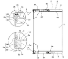
以下、図1〜図4を参照しながら、本発明に係るファイバードラムの実施形態の一例を説明する。
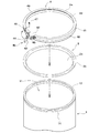
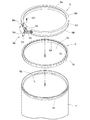
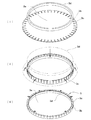
図1は本例のファイバードラムaの正面図で、要部を一部切欠し断面で表すと共に、該断面部分を拡大して示している。図2はこのファイバードラムaの上端部分の分解斜視図であって、上面側から見たものを示している。図3はこのファイバードラムaの下端部分の分解斜視図であって、底面側から見たものを示している。図4は底蓋3の組み立て工程を示す斜視図であって、底面側から見たものを示している。
Hereinafter, an example of an embodiment of a fiber drum according to the present invention will be described with reference to FIGS.
FIG. 1 is a front view of the fiber drum a of the present example, in which the main part is partially cut away and shown in cross section, and the cross section is shown enlarged. FIG. 2 is an exploded perspective view of the upper end portion of the fiber drum a as viewed from the upper surface side. FIG. 3 is an exploded perspective view of the lower end portion of the fiber drum a, as viewed from the bottom side. FIG. 4 is a perspective view showing an assembling process of the
本例のファイバードラムaは、板紙製の円筒状胴部1の上面開口11を金属製の上蓋2で閉塞し、下面開口12を板紙製の底蓋3で閉塞すると共に、上蓋2を上側締め具4で締め付けて閉塞状態を保持し、底蓋3を底側締め具5で締め付けて閉塞状態を保持している。
The fiber drum a of this example closes the upper surface opening 11 of the cylindrical body 1 made of paperboard with a metal
円筒状胴部1は、クラフトライナー紙を主材としてこれを紙管製造機により複数層に平巻き積層したものであり、上端から下端にわたり、一定の直径を有する円筒体に形成されている。 The cylindrical body 1 is obtained by laminating a kraft liner paper as a main material into a plurality of layers by a paper tube manufacturing machine, and is formed into a cylindrical body having a constant diameter from the upper end to the lower end.
円筒状胴部1の上面開口11の開口縁には、円筒状胴部1の上端縁を内巻きに曲成したリング状部13が形成されている。また、円筒状胴部1の外周におけるリング状部13の下方近傍箇所には、環状の上側溝部14が円筒状胴部1の全周にわたって凹設されている。
上側溝部14は、内巻きに曲成したリング状部13の直下に設けることが望ましい。また、上側溝部14は、リング状部と同等か若しくはそれよりも深くなるように溝を形成することが好ましい。このように形成すると、円筒状胴部の開口縁の剛性を高くすることができ、後述する上側締め具4の環状体4aの上下方向の固定がより強固にできる。
At the opening edge of the upper surface opening 11 of the cylindrical body 1, a ring-shaped
It is desirable that the
上面開口11は、金属製の上蓋2により閉塞されている。上蓋2は、リング状部13の内側を閉塞可能な径を有する円板状の上蓋本体2aと、この上蓋本体2aの外周縁から外側に向けて延出しリング状部13に上方から被嵌する逆U字形の掛止部2bとからなり、掛止部2bの内側にはパッキン2cが装填されている。
The upper surface opening 11 is closed by a metal
円筒状胴部1の外周における下面開口12の近傍箇所には、環状の下側溝部15が円筒状胴部1の全周にわたって凹設されている。円筒状胴部1の下面開口12は、円板状の底蓋3により閉塞されている。底蓋3は、下面開口12の内側に下方から嵌め込むことができるように下面開口12よりも若干小さな径を有する円板状の底蓋本体3aと、この底蓋本体3aの外周縁に適宜間隔ごとに連設された下方に折れ曲がる垂下片3bと、垂下片3bの下端に連設され内側に折れ曲がる折り返し片3cとからなり、垂下片3bおよび折り返し片3cの内側には、底蓋3と一体化する紙製の補強リング3dが垂下片3bと折り返し片3cで保持されている。
なお、内容物の重量が大きい場合などは、底蓋3が撓まないよう板紙製の底蓋3にベニア板を重ねて補強することもでき、また、補強リング3dを底蓋3と一体化する際に接着などの手段により固定することもできる。
An annular
In addition, when the weight of the contents is large, it is possible to reinforce by overlapping a veneer plate on the
図4は、底蓋3の組み立て工程を示す斜視図であって、底面側から見たものを示している。図4(i)および(ii)に示すように、周囲に中心に向かってスリットが入った底蓋本体3aを断面が矩形の補強リング3dを包むように立てて、折り返し片3cを形成する。次に、図4(iii)に示すように、折り返し片3cをさらに、補強リング3dに沿って包むようにもう一度折り返し、コの字状に補強リング3dを囲むようにして底蓋本体3aと補強リング3dを一体として底蓋3を形成する。底蓋本体3aに設けられるスリットは、折り返した際に、折り返し片同士が干渉しないように形成しておく。
FIG. 4 is a perspective view showing the assembly process of the
下側溝部15は、補強リング3dを囲む部分の底蓋3の厚み程度下面開口12から離れた箇所に設けることが望ましい。また、下側溝部15は、図1の断面に示すように、補強リング3dと並ぶ程度に深くなるように溝を形成することが好ましい。このように形成すると、後述する下側締め具5の環状体5aの上下方向の固定がより強固にできる。
The
上側締め具4は、鉄製の環状体4aと、鉄製のロック部材4bからなる。環状体4aは帯状の鉄製リング41の一部にスリット42を設けて縮径可能に形成され、その縮径状態をロック部材4bにより解除可能にロックされる。
The
ロック部材4bは、環状体4aの一端部位に基端側を回動自在に連結した操作レバー43と、この操作レバー43の適所に設けた開口44と、環状体4aの他端部位に基端側を回動自在に連結し先端側を操作レバー43の中間部位に回動自在に連結した連結リング45と、環状体4aにおける前記一端部位の近傍に形成された差込孔46を備える。
The
そして、操作レバー43を前記一端部位方向へ回動して環状体4aに沿わせると、連結リング45を介して環状体4aの他端部位が一端部位側に引き寄せられ、これにより環状体4aが縮径すると共に、その縮径状態がロックされるようになっている。
Then, when the
さらに、操作レバー43をロックするために、樹脂製のロックピン47が、操作レバー43の開口44と環状体4aの差込孔46に差し込まれるようになっている。操作レバーのロックを解除するには、このロックピンを破壊すればよい。その後、操作レバー43を前記他端部位方向へ回動させ前記一端部位から離すと、スリット42が拡がり、環状体4aが拡径するようになっている。
Further, in order to lock the
また、上側締め具4は、上側溝部14に係合する下係合面48を環状体4aの下縁全長にわたって備えると共に、上蓋2における掛止部2aの上縁に係合する上係合面49を、環状体4aの上縁全長にわたって備えている。下係合面48は、上側溝部14に嵌合自在な断面凸型状に形成されている。
The
底側締め具5は、鉄製の環状体5aと、鉄製のロック部材5bからなる。環状体5aは帯状の鉄製リング51の一部にスリット52を設けて縮径可能に形成され、その縮径状態をロック部材5bにより解除可能にロックされる。
The bottom-side fastener 5 includes an iron
ロック部材5bは、環状体5aの一端部位に基端側を回動自在に連結した操作レバー53と、この操作レバー53の適所に設けた開口54と、環状体5aの他端部位に基端側を回動自在に連結し先端側を操作レバー53の中間部位に回動自在に連結した連結リング55と、環状体5aにおける前記一端部位の近傍に形成された差込孔56を備える。
The
そして、操作レバー53を前記一端部位方向へ回動して環状体5aに沿わせると、連結リング55を介して環状体5aの他端部位が一端部位側に引き寄せられ、これにより環状体5aが縮径すると共に、その縮径状態がロックされるようになっている。
Then, when the
さらに、操作レバー53をロックするために、樹脂製のロックピン57が、操作レバー53と環状体5aの開口54の差込孔56に差し込まれるようになっている。操作レバー53のロックを解除するには、このロックピンを破壊すればよい。その後、操作レバー53を前記他端部位方向へ回動させ前記一端部位から離すと、スリット52が拡がり、環状体5aが拡径するようになっている。
Further, in order to lock the
なお、底側締め具5におけるロック部材5bは、操作レバー53の開閉操作によらない構造、たとえば、環状体5aに樹脂製ベルトを一端部位と他端部位にかけまわしてロックする構造でもよい。このようにするとファイバードラムaのコーナー部位に操作レバー53のような突出物を設けなくて済むので、ファイバードラムaを移動する際に斜めに傾斜させて転がしやすくなる。
The
また底側締め具5は、底側溝部15に係合する上係合面58を環状体5aの上縁全長にわたって備えると共に、底蓋3の下縁に係合する下係合面59を環状体5aの下縁全長にわたって備えている。
上係合面58は底側溝部15に嵌合自在な断面凸型状に形成されており、下係合面59は、下面開口12の開口縁を覆って内側に廻り込み折り返し片3cの下面に係合するよう形成されている。
The bottom-side fastener 5 has an
The
このような構成となる本例のファイバードラムaによれば、上側締付け具4により上蓋2を締め付けた際、環状体4aによる縮径方向への締付け力により上蓋2が上面開口11内に固定されると共に、下係合面48が上側溝部14に係合し、上係合面49が上蓋2の掛止部2bの上縁に係合して、使用中や輸送中に必要な円筒状胴部の開口縁の強度を保持しつつ上蓋2を強固に固定する。
また、底側締付け具5により底蓋3を締め付けた際、環状体5aによる縮径方向への締付け力により底蓋3が下面開口12内に固定されると共に、上係合面58が底側溝部15に係合し、下係合面59が底蓋3の下縁に係合して、使用中や輸送中に必要な円筒状胴部1の開口縁の強度を保持しつつ底蓋3を強固に固定する。
さらに、ロック部材4b、5bの操作により環状体4a,5aの縮径状態を解除すれば、環状体4a,5aによる前記締め付けが開放されるために、上下の係合面48,49、58,59による前記係合が解除され、上蓋2および底蓋3を容易に取り外すことができる。したがって、ファイバードラムaは、再利用が容易な円筒状胴部1等の紙の部材と上蓋2や締め付け具4,5等の金属等を含む硬質部材とに簡単に分離することができる。
According to the fiber drum a of the present example having such a configuration, when the
Further, when the
Furthermore, if the reduced diameter state of the
また、上側締め具4において、環状体4aの上縁全長に形成された上係合面49と、下縁全長に形成され円筒状胴部の上側溝部に嵌合した下係合面48とで上蓋2を挟持するので、上蓋2の固定をより確実にすることができる。また、上側締め具4が上蓋2および上面開口11の周縁を覆うようになるので、ファイバードラムaにおける上側のコーナー部位(上面開口縁周り)の強度が向上し、輸送時や落下時などにおける衝突が生じても変形しにくい。
Further, in the
さらに、底側締め具5において、環状体5aの上縁全長に形成され円筒状胴部の下側溝部に嵌合した上係合面58と、下縁全長に形成された下係合面59とで底蓋3を挟持するので、底蓋3と底側締め具5の固定をより確実にすることができる。また、底側締め具5が底蓋3および下面開口12の周縁を覆うようになるので、ファイバードラムaにおける下側のコーナー部位(下面開口縁周り)の強度が向上し、輸送時や落下時などにおける衝突が生じても変形しにくい。
Further, in the bottom-side fastener 5, an
加えて、底蓋3の周縁部位が垂下片3b、折り返し片3c、補強リング3dにより補強されると共に、底側締め具5の下係合面59が折り返し片3cの下面に係合し、補強リング3dを支持するので、底蓋3の抜けをより確実に防止することができる。
In addition, the peripheral portion of the
1:円筒状胴部、
2:上蓋、 2a:上蓋本体、2b:係止部、2c:パッキン、
3:底蓋、 3a:底蓋本体、3b:垂下片、3c:折り返し片、
3d:補強リング,
4:上側締め具、 4a:環状体、4b:ロック部材、
5:底側締め具、 5a:環状体、5b:ロック部材、
11:上面開口、12:下面開口、13:リング状部、14:上側溝部、
15:下側溝部、
48:下係合面、49:上係合面、
58:上係合面、59:下係合面
1: cylindrical body,
2: upper lid, 2a: upper lid body, 2b: locking portion, 2c: packing,
3: bottom lid, 3a: bottom lid body, 3b: hanging piece, 3c: folded piece,
3d: Reinforcing ring,
4: upper fastener, 4a: annular body, 4b: lock member,
5: bottom side fastener, 5a: annular body, 5b: lock member,
11: Upper surface opening, 12: Lower surface opening, 13: Ring-shaped portion, 14: Upper groove portion,
15: Lower groove,
48: Lower engagement surface, 49: Upper engagement surface,
58: Upper engagement surface, 59: Lower engagement surface
Claims (6)
前記円筒状胴部において、前記上面開口の口縁は前記円筒状胴部の上端縁を内巻きに曲成したリング状部であり、且つ前記リング状部の下方近傍には環状の上側溝部が、前記下面開口の近傍には環状の底側溝部がそれぞれ凹設されており、
前記上側溝部は、内巻きに曲成したリング状部の直下に設けるとともに、リング状部と同等か若しくはそれよりも深くなるように溝を形成し、
前記上蓋は前記リング状部に係合する掛止部を周縁に有し、
前記それぞれの締め具は、硬質材料からなる縮径可能な帯状の環状体と、該環状体の縮径状態をロックするロック部材からなり、
さらに前記上側締め具は、前記上側溝部に係合する下係合面と、前記上蓋の上縁に係合する上係合面を前記環状体周縁に備え、
前記底側締め具は、前記底側溝部に係合する上係合面と、前記底蓋の下縁に係合する下係合面を前記環状体周縁に備え、
前記上側締め具による前記締め付けがなされた状態で、前記リング状部の外周に着脱可能に嵌着した前記環状体と、前記上係合面および前記下係合面の前記係合とにより前記上蓋を保持して、 前記上面開口が閉塞される一方、
前記底側締め具による前記締め付けがなされた状態で、前記下面開口の外周に着脱可能に嵌着した前記環状体と、前記上係合面および下係合面の前記係合とにより前記底蓋を保持して、前記下面開口が閉塞されるよう形成したことを特徴とするファイバードラム。 The upper surface opening of the cylindrical body made of paper material is closed with the upper lid, the lower surface opening is closed with the bottom lid, the closed state with the upper lid is the upper fastener, and the closed state with the bottom lid is the lower side fastener, respectively. It is a fiber drum that is tightened,
In the cylindrical body part, the lip of the upper surface opening is a ring-shaped part formed by bending an upper end edge of the cylindrical body part inwardly, and an annular upper groove part is provided in the vicinity of the lower part of the ring-shaped part. However, in the vicinity of the lower surface opening, annular bottom groove portions are respectively recessed.
The upper groove portion is provided immediately below the ring-shaped portion bent in an inner winding, and forms a groove so as to be equal to or deeper than the ring-shaped portion,
The upper lid has a latching portion on the periphery for engaging with the ring-shaped portion,
Each of the fasteners comprises a band-shaped annular body made of a hard material and capable of reducing the diameter, and a lock member that locks the reduced diameter state of the annular body,
The upper fastener further includes a lower engagement surface that engages with the upper groove portion and an upper engagement surface that engages with the upper edge of the upper lid on the periphery of the annular body,
The bottom-side fastener includes an upper engagement surface that engages with the bottom-side groove and a lower engagement surface that engages with a lower edge of the bottom lid on the periphery of the annular body,
The upper lid is formed by the annular body detachably fitted to the outer periphery of the ring-shaped portion in the state where the upper fastener is tightened, and the engagement of the upper engagement surface and the lower engagement surface. While holding the upper surface opening,
The bottom cover is formed by the annular body detachably fitted to the outer periphery of the lower surface opening and the engagement of the upper engagement surface and the lower engagement surface in the state where the bottom side fastener is tightened. The fiber drum is formed such that the lower surface opening is closed.
Priority Applications (1)
| Application Number | Priority Date | Filing Date | Title |
|---|---|---|---|
| JP2010220160A JP5311684B2 (en) | 2010-09-30 | 2010-09-30 | Fiber drum |
Applications Claiming Priority (1)
| Application Number | Priority Date | Filing Date | Title |
|---|---|---|---|
| JP2010220160A JP5311684B2 (en) | 2010-09-30 | 2010-09-30 | Fiber drum |
Publications (2)
| Publication Number | Publication Date |
|---|---|
| JP2012071885A JP2012071885A (en) | 2012-04-12 |
| JP5311684B2 true JP5311684B2 (en) | 2013-10-09 |
Family
ID=46168153
Family Applications (1)
| Application Number | Title | Priority Date | Filing Date |
|---|---|---|---|
| JP2010220160A Active JP5311684B2 (en) | 2010-09-30 | 2010-09-30 | Fiber drum |
Country Status (1)
| Country | Link |
|---|---|
| JP (1) | JP5311684B2 (en) |
Families Citing this family (3)
| Publication number | Priority date | Publication date | Assignee | Title |
|---|---|---|---|---|
| CN104973310A (en) * | 2015-07-07 | 2015-10-14 | 句容市三圆制桶有限公司 | Paper bucket with locking hoop and making method thereof |
| CN104973311A (en) * | 2015-07-07 | 2015-10-14 | 句容市三圆制桶有限公司 | Paper bucket with locking hoop |
| KR102698412B1 (en) * | 2022-12-27 | 2024-08-22 | 심광주 | fastening bands for pails can upper plate |
Family Cites Families (7)
| Publication number | Priority date | Publication date | Assignee | Title |
|---|---|---|---|---|
| JPS58143319U (en) * | 1982-03-19 | 1983-09-27 | 株式会社昭和丸筒 | Assembly type exterior body |
| JPH01147936U (en) * | 1988-03-30 | 1989-10-13 | ||
| JP2670741B2 (en) * | 1993-08-27 | 1997-10-29 | 太陽シールパック株式会社 | Fiber drum |
| JP2002114247A (en) * | 2000-10-10 | 2002-04-16 | Taiyo Shiirupatsuku Kk | Lever type tightening band |
| JP2005014958A (en) * | 2003-06-25 | 2005-01-20 | Daikan Kk | Trunk of fiber drum, lid of the same, and fiber drum |
| JP4529066B2 (en) * | 2003-10-28 | 2010-08-25 | ソニー株式会社 | Packaging equipment |
| JP3151911U (en) * | 2009-04-28 | 2009-07-09 | 本州リーム株式会社 | Fiber drum |
-
2010
- 2010-09-30 JP JP2010220160A patent/JP5311684B2/en active Active
Also Published As
| Publication number | Publication date |
|---|---|
| JP2012071885A (en) | 2012-04-12 |
Similar Documents
| Publication | Publication Date | Title |
|---|---|---|
| US7581670B2 (en) | Shipping container | |
| JP6539660B2 (en) | Container, closing ring, and method of assembling container | |
| US10060455B2 (en) | Clip for a knock-down structure | |
| EP2097333B1 (en) | A container and container closure | |
| US9481488B2 (en) | Pallet assembly and a lid apparatus for the pallet assembly | |
| JP5311684B2 (en) | Fiber drum | |
| US20130306497A1 (en) | Paint container with a releasably secured liner | |
| CA2656641A1 (en) | Buckling clamshell container | |
| WO2009153222A1 (en) | Packaging with a swivelling handle for locking a lid on a container suitable for foodstuff or painting | |
| CA1078338A (en) | Method and structure for retaining shipping drums on pallets | |
| JP2006525919A (en) | Container-sealer structure | |
| KR20080105830A (en) | Packing box with lock | |
| JP5864225B2 (en) | Case for roll products | |
| JP2001206409A (en) | Synthetic resin container with cover | |
| EP1785365B1 (en) | Lid for a container-drum | |
| JP3151911U (en) | Fiber drum | |
| GB2488211A (en) | Securing a liner in a paint container | |
| JP2016216059A (en) | Pallet | |
| US20060138141A1 (en) | Reduced thickness cover | |
| KR102000723B1 (en) | Container | |
| JP2670741B2 (en) | Fiber drum | |
| JP3180260U (en) | Packaging container | |
| JPH0437059Y2 (en) | ||
| JP2535087Y2 (en) | Square container | |
| JP2007022564A (en) | Fiber drum |
Legal Events
| Date | Code | Title | Description |
|---|---|---|---|
| A621 | Written request for application examination |
Free format text: JAPANESE INTERMEDIATE CODE: A621 Effective date: 20130123 |
|
| A871 | Explanation of circumstances concerning accelerated examination |
Free format text: JAPANESE INTERMEDIATE CODE: A871 Effective date: 20130123 |
|
| A975 | Report on accelerated examination |
Free format text: JAPANESE INTERMEDIATE CODE: A971005 Effective date: 20130207 |
|
| A977 | Report on retrieval |
Free format text: JAPANESE INTERMEDIATE CODE: A971007 Effective date: 20130405 |
|
| A131 | Notification of reasons for refusal |
Free format text: JAPANESE INTERMEDIATE CODE: A131 Effective date: 20130412 |
|
| A521 | Request for written amendment filed |
Free format text: JAPANESE INTERMEDIATE CODE: A523 Effective date: 20130608 |
|
| TRDD | Decision of grant or rejection written | ||
| A01 | Written decision to grant a patent or to grant a registration (utility model) |
Free format text: JAPANESE INTERMEDIATE CODE: A01 Effective date: 20130628 |
|
| A61 | First payment of annual fees (during grant procedure) |
Free format text: JAPANESE INTERMEDIATE CODE: A61 Effective date: 20130701 |
|
| R150 | Certificate of patent or registration of utility model |
Free format text: JAPANESE INTERMEDIATE CODE: R150 Ref document number: 5311684 Country of ref document: JP Free format text: JAPANESE INTERMEDIATE CODE: R150 |
|
| R250 | Receipt of annual fees |
Free format text: JAPANESE INTERMEDIATE CODE: R250 |
|
| R250 | Receipt of annual fees |
Free format text: JAPANESE INTERMEDIATE CODE: R250 |
|
| R250 | Receipt of annual fees |
Free format text: JAPANESE INTERMEDIATE CODE: R250 |
|
| R250 | Receipt of annual fees |
Free format text: JAPANESE INTERMEDIATE CODE: R250 |
|
| R250 | Receipt of annual fees |
Free format text: JAPANESE INTERMEDIATE CODE: R250 |
|
| R250 | Receipt of annual fees |
Free format text: JAPANESE INTERMEDIATE CODE: R250 |
|
| R250 | Receipt of annual fees |
Free format text: JAPANESE INTERMEDIATE CODE: R250 |
|
| R250 | Receipt of annual fees |
Free format text: JAPANESE INTERMEDIATE CODE: R250 |
|
| R250 | Receipt of annual fees |
Free format text: JAPANESE INTERMEDIATE CODE: R250 |
|
| R250 | Receipt of annual fees |
Free format text: JAPANESE INTERMEDIATE CODE: R250 |