JP5305261B2 - Heating element manufacturing method and heating element manufacturing apparatus - Google Patents
Heating element manufacturing method and heating element manufacturing apparatus Download PDFInfo
- Publication number
- JP5305261B2 JP5305261B2 JP2008175451A JP2008175451A JP5305261B2 JP 5305261 B2 JP5305261 B2 JP 5305261B2 JP 2008175451 A JP2008175451 A JP 2008175451A JP 2008175451 A JP2008175451 A JP 2008175451A JP 5305261 B2 JP5305261 B2 JP 5305261B2
- Authority
- JP
- Japan
- Prior art keywords
- exothermic composition
- mold
- heating element
- seal
- hole
- Prior art date
- Legal status (The legal status is an assumption and is not a legal conclusion. Google has not performed a legal analysis and makes no representation as to the accuracy of the status listed.)
- Expired - Fee Related
Links
- HZXQANVLBFTSTO-YJUROLOESA-N C/C=C(/C1)\C1=N Chemical compound C/C=C(/C1)\C1=N HZXQANVLBFTSTO-YJUROLOESA-N 0.000 description 1
- KMWVPTJQDCPHKA-UHFFFAOYSA-N CC(C)(C=C)C(C=C)=N Chemical compound CC(C)(C=C)C(C=C)=N KMWVPTJQDCPHKA-UHFFFAOYSA-N 0.000 description 1
Images


Abstract
Description
本発明は、鉄粉等の磁性粉を含有する含余剰水発熱組成物を使用した発熱体を製造するための、ブリッジ防止をし、成形部へ含余剰水発熱組成物の擦り切りと充填を同時に行う一回平滑充填する、含余剰水発熱組成物供給装置による含余剰水発熱組成物の連続供給、及び、シール時の含余剰水発熱組成物を成形した発熱組成物成形体の型崩れ防止及び型崩れ断片のシールへの影響を防止する、少なくとも余白値が、0.1〜60であるシール型
によるシールを要素とする発熱体製造方法、シール型、含余剰水発熱組成物供給装置、発熱体製造装置並びに発熱体に関するものである。
The present invention prevents bridging for producing a heating element using an excess water exothermic composition containing magnetic powder such as iron powder, and simultaneously wears and fills the excess water exothermic composition into the molded part. Performing smooth filling once, continuous supply of the surplus water exothermic composition by the surplus water exothermic composition supply device, and prevention of shape loss of the exothermic composition molded body obtained by molding the surplus water exothermic composition at the time of sealing, and A heating element manufacturing method, a sealing mold, an excess water-containing exothermic composition supplying device, an exotherm, which uses a sealing mold with a sealing mold having a margin value of 0.1 to 60 as an element to prevent the influence of the shape loss fragment on the sealing The present invention relates to a body manufacturing apparatus and a heating element.
従来、使い捨てカイロ製造装置には特許文献1に記載されるものがある。この使い捨て
カイロ製造装置は、磁性粉を含有する発熱剤が収容されたホッパーと、外周に発熱剤を収
容可能な計量凹部が周方向に複数形成され且つホッパー内の発熱剤を計量凹部内に保持し
て回転により搬送する計量ドラムと、計量ドラムにより搬送された発熱剤が計量凹部から
転移される転移ドラムと、発熱剤を挟むように重ね合わされた第1シート及び第2シート
を、発熱剤の周辺部分でシールするためのシールロールと、シール後の両シートをカット
してカイロ1個ずつに切り取っていくカットロールと、切り取り後のカイロを搬送する搬
送ベルトとを備えている。
Conventional disposable body warmer manufacturing apparatuses include those described in
計量ドラムには、その各計量凹部の底部に電磁石を使用し、転移ドラムの外周には、計
量凹部から転移される発熱組成物を収容するための収容凹部が、計量ドラムの計量凹部に
対応するように周方向に複数形成され、その各収容凹部の底部に永久磁石が設けられてい
る。そして、この永久磁石により、転移ドラムの外周に巻き付けられた第1シートを介し
て、計量凹部内の発熱剤を収容凹部内に吸着するようになっている。
The measuring drum uses an electromagnet at the bottom of each measuring recess, and an accommodating recess for accommodating the exothermic composition transferred from the measuring recess corresponds to the measuring recess of the measuring drum on the outer periphery of the transfer drum. Thus, a plurality of magnets are formed in the circumferential direction, and a permanent magnet is provided at the bottom of each receiving recess. And by this permanent magnet, the heat generating agent in a measurement recessed part is adsorb | sucked in an accommodation recessed part via the 1st sheet | seat wound around the outer periphery of the transfer drum.
他の使い捨てカイロ製造装置には特許文献2に記載されるものがある。この使い捨てカ
イロ製造装置は、磁性粉を含有する発熱剤が収容されたホッパーと、外周に発熱剤を収容
可能な計量凹部が周方向に複数形成され且つホッパー内の発熱剤を計量凹部内に保持して
回転により搬送する計量ドラムと、該計量ドラムにより搬送された発熱剤が計量凹部から
転移される転移ドラムとを備えた使い捨てカイロ製造装置において、ホッパー内の発熱剤
を計量凹部内に吸着するための磁石を、計量ドラムの内側のホッパーに対応する位置に計
量ドラムの回転方向に移動しないように設け、ホッパーの内部に、前記磁石に対して前記
回転方向の下手側に配置され且つ計量ドラムとの間隔がその下手側ほど狭くなる押圧片に
よって、計量ドラムの回転により計量凹部の近傍の発熱剤を該計量凹部に押し込む押圧手
段を設け、該押圧手段よりも前記下手側に、計量凹部外の余分の発熱剤を計量ドラムから
除去する除去手段を設けると共に、前記押圧手段による押圧の解除位置と、転移ドラムへ
の発熱剤の転移位置を計量ドラムの上部側に配置し、該計量ドラムの回転により、計量凹
部内の発熱剤を該計量ドラムの上部側を経て、前記解除位置から前記転移位置へと搬送す
るようにしたものである。
Another disposable warmer manufacturing apparatus is described in
他の使い捨てカイロ製造装置には特許文献3に記載されるものがある。この使い捨てカ
イロ製造装置は、加圧送給ポンプ、押し出しノズル、接着剤塗布部を設けた積層包装体の
製造装置、回転制御される筒状のドラム本体に、所望形状の抜孔が円周方向に設けられる
パターンロールと、パターンロール外周面に接離自在に設けるバックアップロールと、パ
ターンロール内で、抜孔側に指向させると共に、粘稠質素材を薄板状と成す吐出口を備え
る素材押出ノズルと、素材押出ノズルに粘稠質素材を加圧送給するポンプと、パターンロ
ールとバックアップロール間およびプレスロールに基材シートを走行させる第一走行手段
と、基材シート上に第二走行手段によって走行させる被膜シートを積層被覆させるプレス
ロールと、被膜シートに接着剤を塗布する接着剤塗布部を設けた積層包装体の製造装置で
ある。
Another disposable warmer manufacturing apparatus is described in
従来の装置では、ホッパーから転移位置までの間で計量ドラムの下部側を経て発熱剤を
搬送することから、その範囲では発熱剤が脱落しないように電磁石を着磁しておき、一方
、計量凹部から収容凹部へと発熱剤を転移させる際に、発熱剤を収容凹部側の永久磁石に
吸着させるために、計量凹部側の電磁石を減磁するようになっている。そのため、計量ド
ラムの内部に周方向に着磁室と減磁室とを設け、電磁石の着磁と減磁とを制御する必要が
ある。
In the conventional apparatus, since the heating agent is transported through the lower side of the measuring drum from the hopper to the transfer position, the electromagnet is magnetized so that the heating agent does not fall off in that range, while the measuring recess When the heat generating agent is transferred from the housing to the receiving recess, the electromagnet on the measuring recess is demagnetized in order to attract the heating agent to the permanent magnet on the receiving recess. Therefore, it is necessary to provide a magnetizing chamber and a demagnetizing chamber in the circumferential direction inside the measuring drum to control the magnetization and demagnetization of the electromagnet.
従って、計量ドラムの内側に電磁石の配線を設けなければならず、装置が複雑になる問
題がある。また、着磁及び減磁を行なうための制御装置を設ける必要があり、装置全体と
して高価になってしまう。更に、装置を高速化するほど電磁石の着磁と滅磁との制御が難
しくなるため、高速な装置を製造することが非常に困難である。
Therefore, there is a problem that the electromagnet wiring must be provided inside the measuring drum, which complicates the apparatus. Further, it is necessary to provide a control device for performing magnetization and demagnetization, and the entire device becomes expensive. Further, since the control of the magnetization and demagnetization of the electromagnet becomes more difficult as the speed of the apparatus is increased, it is very difficult to manufacture a high-speed apparatus.
特許文献2の装置では、計量ドラムの回転の最高点と回転の最低点との間に発熱剤を含
むホッパーを設け、固定磁石により計量凹部へ発熱剤を吸着させ、回転の最高点に回転搬
送させ、計量凹部から収容凹部を備えた転移ドラムの収容凹部へと発熱剤を転移させる。
転移は重力による転移効果が期待できず、該収容凹部は、計量ドラムの計量凹部に対応す
るように、転移ドラムの外周に周方向に等間隔をおいて複数形成されると共に、軸心方向
に1列又は複数列(例えば2列)形成されている。該収容凹部には、その底面の略全体に
磁石(永久磁石)が敷設されており、この磁石により計量凹部内の発熱剤を転移位置で吸
着するようになっている。即ち、各収容凹部に磁石を備えた転移ドラムを使わなければな
らず、装置が複雑になる問題がある。また、各収容凹部に磁石を備える必要があり、装置
全体として高価になってしまう。更に、装置を高速化するほど回転体から回転体への転移
の制御が難しくなり、更にホッパーの内部に設けられた押圧手段と磁石で発熱剤を該計量
凹部に押し込む仕組みがあるが、高速になるほど押圧手段による計量凹部への押し込みは
むらがでて、難しくなり、押し込みが不十分になる。また、該押圧手段よりも前記下手側
に、計量凹部外の余分の発熱剤を計量ドラムから除去する除去手段を設けているが、計量
凹部外の余分の発熱剤を除去することが実質上困難で、計量凹部内の発熱剤の表面を粗面
化する畏れがあり、高速になるほどそれが顕著になる。また、第2押圧片の端部を計量ド
ラムの外周に略当接させる場合でも、第2押圧片は計量ドラムの回転方向に沿って外周を
押さえることになり、計量凹部への押し込みは不十分であり、押し込みにむらがでて、計
量凹部に余盛りされた発熱剤を押圧手段によって除去することは難しく、高速になるほど
不可能になり、高速な装置を製造することが非常に困難である。
In the apparatus of
The transfer cannot be expected to have a transfer effect due to gravity, and a plurality of the receiving recesses are formed on the outer periphery of the transfer drum at equal intervals in the circumferential direction so as to correspond to the measurement recesses of the measurement drum, and in the axial direction. One row or a plurality of rows (for example, two rows) are formed. A magnet (permanent magnet) is laid on substantially the entire bottom surface of the accommodating recess, and the heat generating agent in the measuring recess is attracted by the magnet at the transfer position. That is, it is necessary to use a transfer drum provided with a magnet in each housing recess, and there is a problem that the apparatus becomes complicated. Moreover, it is necessary to provide a magnet in each accommodation recessed part, and it will become expensive as the whole apparatus. Furthermore, the higher the speed of the device, the more difficult it becomes to control the transition from the rotating body to the rotating body, and there is a mechanism to push the heating agent into the measuring recess with the pressing means and magnet provided inside the hopper. Indeed, the pressing by the pressing means is uneven and difficult, and the pressing becomes insufficient. Further, a removing means for removing the extra heating agent outside the measuring recess from the measuring drum is provided on the lower side of the pressing means, but it is substantially difficult to remove the extra heating agent outside the measuring recess. Thus, there is a tendency to roughen the surface of the heat generating agent in the measurement recess, and this becomes more remarkable as the speed increases. Even when the end of the second pressing piece is substantially in contact with the outer periphery of the measuring drum, the second pressing piece presses the outer periphery along the rotation direction of the measuring drum, and the pressing into the measuring recess is insufficient. It is difficult to remove the exothermic agent accumulated in the measurement recess by pressing means, and it becomes impossible as the speed increases, and it is very difficult to manufacture a high-speed device. .
また、水を発熱組成物の成分の連結材に使用した含余剰水発熱組成物を成形した発熱組成物成形体を多種サイズ、多種形状の発熱体の製造に使用する場合、発熱組成物成形体を包材の間に挟み、該発熱組成物成形体の周縁部をシールする時に、発熱組成物成形体が型崩れを起こしやすく、シール切れ等のシール不良を起こしやすかった。 Further, when the exothermic composition molded body obtained by molding the surplus water exothermic composition using water as a connecting material of the component of the exothermic composition is used for manufacturing various sizes and shapes of the exothermic composition molded body, Was sandwiched between the packaging materials, and when the peripheral portion of the exothermic composition molded body was sealed, the exothermic composition molded body was liable to lose its shape and easily cause a sealing failure such as a seal breakage.
本発明は、このような従来の問題点に鑑み、シール不良もなく、簡単且つ安価な構成で、高速化も容易に行なうことができる、多種サイズ、多種形状の発熱体を製造するための発熱体製造方法及び発熱体製造装置並びに発熱体を提供することを目的とする。 SUMMARY OF THE INVENTION In view of the above-described conventional problems, the present invention provides heat generation for manufacturing various-sized and various-shaped heating elements that can be easily increased in speed with a simple and inexpensive configuration without sealing failure. The object is to provide a body manufacturing method, a heating element manufacturing apparatus, and a heating element.
本発明の発熱体製造方法は、請求項1に記載の通り、
鉄粉、炭素成分、反応促進剤、水を必須成分とし、JIS−P3801の「2種」の濾紙上に載置される内径29mm×高さ20mmの円柱状貫通孔に充填される発熱組成物から前記濾紙に浸透する水又は水溶液の浸透距離を充填された発熱組成物の測定時の全水分量に比例する該発熱組成物の高さである円柱状貫通孔の高さ(mm)で除した値を百分率で表した値である余剰水値0.5〜80である、容易に、自由に発熱組成物の系外に移動できる水分量である余剰水を含む含余剰水発熱組成物を使用し、型孔を有する成形型により、該含余剰水発熱組成物を発熱組成物成形体に成形をする型成形工程及び基材と被覆材に挟まれた該発熱組成物成形体の周縁部を、空間部とシール部を有するシール型によりシールするシール工程を必須工程とする発熱体製造方法であって、
前記型成形工程は、型孔を有する成形型として、厚さが0.1〜10mmの成形部を周面に有する中空の回転体を設け、前記型孔が前記成形部に設けられた貫通孔であり、前記中空の回転体が厚さが0.1〜10mmの成形部を周面に有する中空の円筒状回転体及び厚さ0.1〜10mmの成形部を有するシート状型を連接したチェーンコンベア状回転体から選ばれた1種であり、
厚さが0.1〜30mmの直線部と先端部を有する板状体で、前記中空の回転体の成形部と対応する周面と当接するブレードを有する含余剰水発熱組成物供給装置と、前記成形部の前記ブレードの前記周面との当接部と対応し、前記成形部の前記ブレードと反対側に回転体の回転に沿って移動しないように設けられた磁石と、基材を前記中空の回転体に供給するための基材供給手段、発熱組成物成形体を基材に載置するための載置装置と、被覆材供給手段とを設け、
前記貫通孔を有する中空の回転体の該貫通孔の開放口側である外周面側に前記基材を位置させ、前記基材に底打ちされた前記貫通孔で、所定の容量及び形状を有する成形部を形成し、搬送されている前記基材上に、
前記中空の回転体の内部に配置された含余剰水発熱組成物供給装置の含余剰水発熱組成物補給部に投入された前記含余剰水発熱組成物を、前記含余剰水発熱組成物補給部の下方に連設されて、ブレードと弾力性や柔軟性のある材料からなるスカートとから平滑充填部を形成し且つ該貫通孔の開口側である内周面に当接する該平滑充填部内に設けられた前記ブレードを、前記中空の回転体の回転進行方向と対抗するように設け、その当接角度(θt)を95゜〜170゜に設定することにより、一回平滑充填システムを構成し、前記ブレードが該貫通孔の開口側を擦り切りながら、前記含余剰水発熱組成物が供給された面と反対側の面側に前記中空の回転体の回転に沿って移動しないように設けた磁石とにより、前記貫通孔の開口側より供給し、前記成形部内に前記含余剰水発熱組成物を一回平滑充填することにより、発熱組成物成形体を成形し、 更に前記基材へ積層し、更に前記被覆材供給手段から供給された前記被覆材を前記発熱組成物成形体と前記基材に被覆し、前記シール工程に搬送し、
前記シール工程においては、前記基材と前記被覆材の間に挟まれた前記発熱組成物成形体の周縁部を前記空間部とシール部を有するシール型を使用してシールすることを特徴とする。
また、請求項2に記載の発熱体製造方法は、請求項1に記載の発熱体製造方法において、
鉄粉、炭素成分、反応促進剤、水を必須成分とし、JIS−P3801の「2種」の濾紙上に載置される内径29mm×高さ20mmの円柱状貫通孔に充填される発熱組成物から前記濾紙に浸透する水又は水溶液の浸透距離を充填された発熱組成物の測定時の全水分量に比例する該発熱組成物の高さである円柱状貫通孔の高さ(mm)で除した値を百分率で表した値である余剰水値0.5〜80である、容易に、自由に発熱組成物の系外に移動できる水分量である余剰水を含む含余剰水発熱組成物を使用し、型孔を有する成形型により、該含余剰水発熱組成物を発熱組成物成形体に成形をする型成形工程及び基材と被覆材に挟まれた該発熱組成物成形体の周縁部を、空間部とシール部を有する
シール型によりシールするシール工程を必須工程とする発熱体製造方法であって、
前記型成形工程は、型孔を有する成形型として厚さが0.1〜10mmの成形部を周面に有する中空の円筒状回転体を設け、前記型孔が成形部に設けられた貫通孔であり、
厚さが0.1〜30mmの直線部と先端部を有する板状体で、前記中空の円筒状回転体の成形部と対応する周面と当接するブレードを有する含余剰水発熱組成物供給装置と、前記ブレードの前記周面との当接部と対応し、前記成形部の前記ブレードと反対側に、前記中空の円筒状回転体の回転に沿って移動しないように設けられ外部固定磁石と、基材を該中空の円筒状回転体に供給するための基材供給手段と、被覆材供給手段とを設け、
前記貫通孔は、前記貫通孔を有する中空の円筒状回転体の半径方向に貫通しており且つ複数個配設されており、前記貫通孔を有する中空の円筒状回転体の該貫通孔の開放口側である外周面側に前記基材を位置させ、前記基材に底打ちされた前記貫通孔で、所定の容量及び形状を有する成形部を形成し、搬送されている前記基材上に、
前記中空の円筒状回転体の内部に配置された含余剰水発熱組成物供給装置の含余剰水発熱組成物補給部に投入された前記含余剰水発熱組成物を、前記含余剰水発熱組成物補給部の下方に連設されて、ブレードと弾力性や柔軟性のある材料からなるスカートとから平滑充填部を形成し且つ該貫通孔の開口側である内周面に当接する該平滑充填部内に設けられた前記ブレードを、前記中空の円筒状回転体の回転進行方向と対抗するように設け、その当接角度(θt)を95゜〜170゜に設定することにより、一回平滑充填システムを構成し、前記ブレードが前記貫通孔の開口側を擦り切りながら、前記ブレードの当接部と対応し前記基材における前記含余剰水発熱組成物が供給された面と反対側の面側に前記中空の円筒状回転体の回転に沿って移動しないように設けられた外部固定磁石とにより、前記貫通孔の開口側より供給し、前記成形部内に前記含余剰水発熱組成物を一回平滑充填することにより、発熱組成物成形体を成形し、 更に前記基材へ積層し、更に前記被覆材供給手段より供給された前記被覆材を前記発熱組成物成形体と前記基材に被覆し、前記シール工程に搬送し、
前記シール工程においては、前記基材と前記被覆材の間に挟まれた前記発熱組成物成形体の周縁部を前記空間部とシール部を有するシール型を使用してシールすることを特徴とする。
また、請求項3に記載の発熱体製造方法は、請求項1に記載の発熱体製造方法において、
鉄粉、炭素成分、反応促進剤、水を必須成分とし、JIS−P3801の「2種」の濾紙上に載置される内径29mm×高さ20mmの円柱状貫通孔に充填される発熱組成物から前記濾紙に浸透する水又は水溶液の浸透距離を充填された発熱組成物の測定時の全水分量に比例する該発熱組成物の高さである円柱状貫通孔の高さ(mm)で除した値を百分率で表した値である余剰水値0.5〜80である、容易に、自由に発熱組成物の系外に移動できる水分量である余剰水を含む含余剰水発熱組成物を使用し、型孔を有する成形型により、該含余剰水発熱組成物を発熱組成物成形体に成形をする型成形工程及び基材と被覆材に挟まれた該発熱組成物成形体の周縁部を、空間部とシール部を有するシール型によりシールするシール工程を必須工程とする発熱体製造方法であって、
前記型成形工程は、型孔を有する成形型として、厚さ0.1〜10mmの成形部を有するシート状型を連接したチェーンコンベア状回転体を設け、前記型孔が前記成形部に設けられた貫通孔であり、前記シート状型は複数のシート状型がチェーンに連接され、前記チェーンコンベア状回転体のフレーム内側に支持された前記チェーンより駆動され、前記貫通孔が前記シート状型に1個以上配設されており、 厚さが0.1〜30mmの直線部と先端部を有する板状体で、前記チェーンコンベア状回転体の前記成形部と対応する面と当接するバネ式自動可動ブレードを有する含余剰水発熱組成物供給装置と、前記バネ式自動可動ブレードの前記周面との当接部と対応し、前記成形部の前記バネ式自動可動ブレードと反対側に、前記チェーンコンベア状回転体の回転に沿って移動しないように設けられ外部固定磁石と、基材を前記チェーンコンベア状回転体に供給するための基材供給手段と、被覆材供給手段とを設け、
前記基材供給手段より供給され、無端状ベルトに支持され、前記チェーンコンベア状回転体の下部のシート状型に当接するように基材を供給し、前記貫通孔付きシート状型を連接したチェーンコンベア状回転体の該貫通孔の開放口側である外面側に、前記基材を位置させ、前記基材に底打ちされた前記貫通孔で、所定の容量及び形状を有するの成形部を形成し、搬送されている前記基材上に、前記チェーンコンベア状回転体の内部に配置された前記含余剰水発熱組成物供給装置の含余剰水発熱組成物補給部に投入された前記含余剰水発熱組成物を、前記含余剰水発熱組成物補給部の下方に連設されて、前記バネ式自動可動ブレードと弾力性や柔軟性のある材料からなるスカートとから平滑充填部を形成し且つ前記貫通孔の開口側である内面側に当接する前記平滑充填部内に設けられた前記バネ式自動可動ブレードが、前記中空の回転体の回転進行方向と対抗するように設けられ、その当接角度(θt)を95゜〜170゜に設定することにより、一回平滑充填システムを構成し、前記ブレードが前記貫通孔の開口側を擦り切りながら、前記バネ式自動可動ブレードの当接部と対応し前記基材における前記含余剰水発熱組成物が供給された面と反対側の面側に前記チェーンコンベア状回転体の回転に沿って移動しないように設けられ外部固定磁石とにより、前記貫通孔の開口側より供給し、前記成形部内に前記含余剰水発熱組成物を一回平滑充填することにより、発熱組成物成形体を成形し、 次に前記チェーンの駆動により連接された複数の前記シート状型のそれぞれの前記シート状型を前記基材より離脱させ、前記基材上に成形された前記発熱組成物成形体を積層し、更に前記被覆材供給手段から供給された前記被覆材を前記発熱組成物成形体と前記基材に被覆し、前記シール工程に搬送し、
前記シール工程においては、前記基材と前記被覆材の間に挟まれた前記発熱組成物成形体の周縁部を前記空間部とシール部を有するシール型を使用してシールすることを特徴とする。
また、本発明の発熱体製造装置は、請求項4に記載の通り、
請求項1乃至3の何れかに記載の発熱体製造方法に使用される発熱体製造装置であって、
厚さが0.1〜10mmの成形部を周面に有する中空の円筒状回転体及び厚さ0.1〜10mmの成形部を有するシート状型を連接したチェーンコンベア状回転体から選ばれた1種である、厚さ0.1〜10mmの貫通孔からなる成形部を周面に有する中空の回転体と、
厚さが0.1〜30mmの直線部と先端部を有する板状体で、中空の回転体の成形部と対応する周面と当接するブレードを有する含余剰水発熱組成物供給装置と、
前記成形部の前記ブレードの前記周面との当接部と対応し、前記成形部の前記ブレードと反対側に、回転体から離して、回転体の回転に沿って移動しないように設けられた磁石と、基材を該中空の回転体に供給するための基材供給手段、発熱組成物成形体を基材に載置するための載置装置と、被覆材供給手段と、
前記基材供給装置から供給される前記基材を搬送し、且つ前記基材を前記平滑充填部に向けて押圧する無端状ベルトとからなり、前記含余剰水発熱組成物供給装置の含余剰水発熱組成物補給部の下方に連設されて、ブレードと弾力性や柔軟性のある材料からなるスカートとから平滑充填部を形成し且つ該貫通孔の開口側である内周面に当接する該平滑充填部内に設けられたブレードを、前記中空の回転体の回転進行方向と対抗するように設け、その当接角度(θt)を95゜〜170゜に設定することにより、一回平滑充填システムを構成し、前記中空の円筒状回転体は、該中空の円筒状回転体の半径方向に貫通する貫通孔が複数個配設されており、前記チェーンコンベア状回転体はチェーンに連接した複数のシート状型を配備し、前記シート型は該シート型の厚み方向に貫通する貫通孔が1個以上配設されており、
前記貫通孔を有する中空の回転体の該貫通孔の開放口側である外周面側に前記基材を位置させ、前記基材に底打ちされた前記貫通孔で、所定の容量及び形状を有する成形部を形成し、搬送されている前記基材上に、
前記中空の回転体の内部に配置された前記含余剰水発熱組成物供給装置の前記含余剰水発熱組成物補給部に投入された前記含余剰水発熱組成物を、前記ブレードが前記貫通孔の開口側を擦り切りながら、前記ブレードの当接部と対応し前記基材における前記含余剰水発熱組成物が供給された面と反対側の面側に前記中空の回転体の回転に沿って移動しないように設けた前記磁石とにより、前記貫通孔の開口側より供給し、移動する前記成形部に前記含余剰水発熱組成物を一回平滑充填することにより、発熱組成物成形体を成形する機能を有することを特徴とする。
Originating thermal body production method of the present invention, as described in
An exothermic composition filled with a cylindrical through-hole having an inner diameter of 29 mm and a height of 20 mm placed on “two types” filter paper of JIS-P3801 with iron powder, carbon component, reaction accelerator and water as essential components The permeation distance of water or aqueous solution penetrating into the filter paper is divided by the height (mm) of the cylindrical through-hole which is the height of the exothermic composition proportional to the total water content at the time of measurement of the exothermic composition filled. A surplus water exothermic composition containing surplus water, which is a surplus water value of 0.5 to 80 , which is a value expressed as a percentage, and can be easily moved out of the exothermic composition system. A mold forming step of forming the excess water exothermic composition into a exothermic composition molded body by using a mold having a mold hole, and a peripheral portion of the exothermic composition molded body sandwiched between the substrate and the covering material The sealing process that seals the space with a sealing mold having a space part and a sealing part is an essential process A heating element manufacturing method of,
In the mold forming step, as a mold having a mold hole, a hollow rotating body having a molded part with a thickness of 0.1 to 10 mm on the peripheral surface is provided, and the mold hole is provided in the molded part. The hollow rotating body is connected to a hollow cylindrical rotating body having a molded part having a thickness of 0.1 to 10 mm on the peripheral surface and a sheet-shaped mold having a molded part having a thickness of 0.1 to 10 mm. It is one kind selected from a chain conveyor-like rotating body,
A plate-like body having a straight portion and a tip portion having a thickness of 0.1 to 30 mm, and a surplus water heating composition supplying device having a blade that comes into contact with a peripheral surface corresponding to a molding portion of the hollow rotating body; Corresponding to the contact portion of the molding portion with the peripheral surface of the blade, a magnet provided on the opposite side of the molding portion to the blade so as not to move along the rotation of the rotating body, and a substrate A base material supply means for supplying the hollow rotating body, a mounting device for mounting the heat generating composition molded body on the base material, and a covering material supply means;
The base material is positioned on the outer peripheral surface side that is the open port side of the through hole of the hollow rotating body having the through hole, and the through hole bottomed on the base material has a predetermined capacity and shape. On the base material being formed and transported,
The surplus water exothermic composition replenishment unit is disposed in the surplus water exothermic composition replenishment unit of the surplus water exothermic composition supply device disposed inside the hollow rotor. Is provided in the smooth filling portion which is formed continuously from the blade and a skirt made of a material having elasticity and flexibility and is in contact with the inner peripheral surface on the opening side of the through hole. The blade is provided so as to oppose the rotation direction of the hollow rotating body, and the contact angle (θt) is set to 95 ° to 170 ° to constitute a one-time smooth filling system, A magnet provided so that the blade does not move along the rotation of the hollow rotating body on the surface side opposite to the surface to which the excess water heating composition is supplied, while scraping the opening side of the through-hole. To supply from the opening side of the through hole. The covering material supplied from the covering material supply means is formed by smooth-filling the surplus water-containing exothermic composition into the forming portion once to form a heat generating composition molded body, and further laminated on the base material. Is coated on the exothermic composition molded body and the substrate, and conveyed to the sealing step,
In the sealing step, the peripheral portion of the exothermic composition molded body sandwiched between the base material and the covering material is sealed using a seal mold having the space portion and a seal portion. .
Also, outgoing heat body manufacturing method according to
An exothermic composition filled with a cylindrical through-hole having an inner diameter of 29 mm and a height of 20 mm placed on “two types” filter paper of JIS-P3801 with iron powder, carbon component, reaction accelerator and water as essential components The permeation distance of water or aqueous solution penetrating into the filter paper is divided by the height (mm) of the cylindrical through-hole which is the height of the exothermic composition proportional to the total water content at the time of measurement of the exothermic composition filled. A surplus water exothermic composition containing surplus water, which is a surplus water value of 0.5 to 80 , which is a value expressed as a percentage, and can be easily moved out of the exothermic composition system. A mold forming step of forming the excess water exothermic composition into a exothermic composition molded body by using a mold having a mold hole, and a peripheral portion of the exothermic composition molded body sandwiched between the substrate and the covering material The sealing process that seals the space with a sealing mold having a space part and a sealing part is an essential process A heating element manufacturing method of,
In the mold forming step, a hollow cylindrical rotating body having a molded part having a thickness of 0.1 to 10 mm on the peripheral surface is provided as a mold having a mold hole, and the mold hole is provided in the molded part. And
A surplus water heating composition supply device comprising a plate-like body having a straight portion and a tip portion having a thickness of 0.1 to 30 mm, and a blade that comes into contact with a peripheral surface corresponding to a molding portion of the hollow cylindrical rotating body And an external fixed magnet provided so as not to move along the rotation of the hollow cylindrical rotating body on the side opposite to the blade of the molding portion, corresponding to a contact portion with the peripheral surface of the blade. A base material supply means for supplying the base material to the hollow cylindrical rotating body, and a coating material supply means,
A plurality of the through holes penetrates in the radial direction of the hollow cylindrical rotating body having the through holes, and a plurality of the through holes are provided, and the through holes of the hollow cylindrical rotating body having the through holes are opened. The base material is positioned on the outer peripheral surface side, which is the mouth side, and a molded part having a predetermined capacity and shape is formed by the through hole bottomed on the base material, and the base material being transported ,
The surplus water exothermic composition is supplied to the surplus water exothermic composition replenishment unit of the surplus water exothermic composition supply device disposed inside the hollow cylindrical rotating body. In the smooth filling portion that is provided below the replenishment portion, forms a smooth filling portion from a blade and a skirt made of elastic or flexible material, and abuts the inner peripheral surface on the opening side of the through hole. The smoothing system is provided once by providing the blade provided to the opposite side of the rotation direction of the hollow cylindrical rotating body and setting the contact angle (θt) to 95 ° to 170 °. The blade is scraped off the opening side of the through-hole, and corresponds to the abutting portion of the blade, and the surface on the surface opposite to the surface to which the surplus water heating composition is supplied in the base material. Along the rotation of a hollow cylindrical rotating body The exothermic fixed magnet provided so as not to move is supplied from the opening side of the through hole, and the excess water exothermic composition is smoothly filled once into the molding portion, thereby forming the exothermic composition molded body. And further laminating the base material, further coating the covering material supplied from the covering material supply means on the exothermic composition molded body and the base material, and transporting to the sealing step,
In the sealing step, the peripheral portion of the exothermic composition molded body sandwiched between the base material and the covering material is sealed using a seal mold having the space portion and a seal portion. .
Further, the heating element manufacturing method according to
An exothermic composition filled with a cylindrical through-hole having an inner diameter of 29 mm and a height of 20 mm placed on “two types” filter paper of JIS-P3801 with iron powder, carbon component, reaction accelerator and water as essential components The permeation distance of water or aqueous solution penetrating into the filter paper is divided by the height (mm) of the cylindrical through-hole which is the height of the exothermic composition proportional to the total water content at the time of measurement of the exothermic composition filled. A surplus water exothermic composition containing surplus water, which is a surplus water value of 0.5 to 80, which is a value expressed as a percentage, and can be easily moved out of the exothermic composition system. A mold forming step of forming the excess water exothermic composition into a exothermic composition molded body by using a mold having a mold hole, and a peripheral portion of the exothermic composition molded body sandwiched between the substrate and the covering material The sealing process that seals the space with a sealing mold having a space part and a sealing part is an essential process A heating element manufacturing method of,
In the mold forming step, a chain conveyor-like rotating body connected to a sheet-shaped mold having a molded portion having a thickness of 0.1 to 10 mm is provided as a mold having a mold hole, and the mold hole is provided in the molded portion. A plurality of sheet-shaped molds connected to a chain and driven by the chain supported inside the frame of the chain conveyor-like rotating body, and the through-hole is formed in the sheet-shaped mold. One or more plate-shaped bodies having a straight portion and a tip portion with a thickness of 0.1 to 30 mm, which are in contact with the surface corresponding to the molded portion of the chain conveyor-like rotating body. Corresponding to the contact portion between the surplus water heating composition supply device having a movable blade and the peripheral surface of the spring-type automatic movable blade, the chain on the opposite side of the spring-type automatic movable blade of the molding portion Combe An external fixed magnet provided so as not to move along with the rotation of the A-shaped rotating body, a base material supplying means for supplying the base material to the chain conveyor-shaped rotating body, and a covering material supplying means;
A chain that is supplied from the base material supply means, is supported by an endless belt, supplies the base material so as to contact the lower sheet-shaped mold of the chain conveyor-like rotating body, and connects the sheet-shaped molds with through holes. The base material is positioned on the outer surface side that is the opening side of the through hole of the conveyor-like rotating body, and a molding part having a predetermined capacity and shape is formed by the through hole bottomed on the base material. And the surplus water contained in the surplus water exothermic composition replenishment section of the surplus water exothermic composition supply device disposed inside the chain conveyor-like rotating body on the substrate being conveyed The exothermic composition is continuously provided below the replenishment unit for the excess water-containing exothermic composition so as to form a smooth filling portion from the spring-type automatic movable blade and a skirt made of an elastic or flexible material, and The inner surface side that is the opening side of the through hole The spring-type automatic movable blade provided in the smooth filling portion that is in contact is provided so as to oppose the rotational traveling direction of the hollow rotating body, and the contact angle (θt) is set to 95 ° to 170 °. Thus, the surplus water heating composition in the base material corresponds to the contact portion of the spring-type automatic movable blade while constituting a smooth filling system once and the blade scrapes off the opening side of the through-hole. Is supplied from the opening side of the through-hole by an external fixed magnet provided so as not to move along the rotation of the chain conveyor-like rotating body on the surface opposite to the surface to which Each of the sheet-like dies of the plurality of sheet-like dies formed by forming the exothermic composition molding by smooth filling once with the excess water-containing exothermic composition and then connected by driving the chain Was detached from the substrate, the heat-generating composition molded body that is molded onto the substrate by laminating, further the base material of the coating material supplied to the heat-generating composition molded article from the coating material supply means coated on, and conveyed to the sealing process,
In the sealing step, the peripheral portion of the exothermic composition molded body sandwiched between the base material and the covering material is sealed using a seal mold having the space portion and a seal portion. .
Moreover, the heating element manufacturing apparatus of the present invention is as described in
A heating element manufacturing apparatus used in the heating element manufacturing method according to any one of
It was selected from a hollow cylindrical rotator having a molded part with a thickness of 0.1 to 10 mm on the peripheral surface and a chain conveyor-like rotator connected with a sheet-like mold having a molded part with a thickness of 0.1 to 10 mm. it is one, a hollow rotating body having a molded portion made of the through hole of the thick 0.1~10mm the peripheral surface,
A surplus water exothermic composition supply device having a blade that comes into contact with a peripheral surface corresponding to a molding portion of a hollow rotating body, in a plate-like body having a straight portion and a tip portion having a thickness of 0.1 to 30 mm ;
Corresponding to the contact portion of the molding portion with the peripheral surface of the blade, the molding portion is provided on the opposite side of the blade from the rotating body so as not to move along with the rotation of the rotating body. A magnet, a base material supply means for supplying the base material to the hollow rotating body, a mounting device for mounting the exothermic composition molded body on the base material, and a covering material supply means;
The surplus water of the surplus water exothermic composition feed device comprising the endless belt that conveys the base material supplied from the base material supply device and presses the base material toward the smooth filling portion. Continuously provided below the exothermic composition replenishment portion, the blade and a skirt made of a flexible or flexible material form a smooth filling portion and abut against the inner peripheral surface on the opening side of the through hole By providing the blade provided in the smooth filling portion so as to oppose the rotational traveling direction of the hollow rotating body and setting the contact angle (θt) to 95 ° to 170 °, the smooth filling system once. The hollow cylindrical rotating body is provided with a plurality of through-holes penetrating in the radial direction of the hollow cylindrical rotating body, and the chain conveyor-shaped rotating body is connected to a chain. Deploy a sheet mold and Type is disposed through holes least one penetrating in the thickness direction of the sheet type,
The base material is positioned on the outer peripheral surface side that is the open port side of the through hole of the hollow rotating body having the through hole, and the through hole bottomed on the base material has a predetermined capacity and shape. On the base material being formed and transported,
The surplus water exothermic composition supplied to the surplus water exothermic composition replenishment unit of the surplus surplus water exothermic composition supply device disposed inside the hollow rotating body, and the blade of the through hole While scraping off the opening side, it does not move along the rotation of the hollow rotating body to the surface side of the base material opposite to the surface supplied with the excess water heating composition corresponding to the contact portion of the blade. A function of forming the exothermic composition molded body by smooth filling once with the excess water exothermic composition into the molded part that is supplied from the opening side of the through-hole and moved by the magnet provided as described above It is characterized by having.
1.成形型の型孔とシール型の空間部との間に、型孔に対して、空間部が、成形型の型孔の開口形状線とそれに対応するシール型の空間部の開口形状線との間の距離である余白距離を前記型孔の高さで除した値である余白値が、0.1〜60である関係を有することにより、シールされた発熱体の発熱組成物成形体側の端部は直線状となるべきところが直線状となり、曲線状となるべきところが曲線状となり、極めて優れた外観を有するものとなり、シール切れ等のシール不良がなく、高収率で発熱体が得られる。
2.シール型の空間部が、余白値0.1〜60、且つ、空間部の高さを型孔の高さで除した値である高さ値1.1〜150を有することにより、更に極めて優れた外観を有するものとなり、シール切れ等のシール不良がなく、高収率で発熱体が得られる。
3.水を発熱組成物の成分の連結材に使用した含余剰水発熱組成物の成形体である発熱組成物成形体を使用し、シール良好な、多種サイズ、多種形状の発熱体の供給が可能になる。
4.含余剰水発熱組成物供給装置はブレードとそれに対応した固定磁石により、含余剰水
発熱組成物を1段で平滑充填(一回平滑充填)できるため、押圧による水分移動にもとず
く含余剰水発熱組成物の流動性消失もなく、含余剰水発熱組成物の流動性を維持したまま、充填ムラもなく、一回で、成形部へ確実に平滑充填でき、電磁石の配線もなく、加圧ポンプ等の加圧操作もなく、構造が非常に簡単で、安価に含余剰水発熱組成物の型成形が可能になる。
5.含余剰水発熱組成物供給装置は含余剰水発熱組成物のブリッジを生ずることなくスム
ースに成形部に一回平滑充填することができるため、発熱組成物成形体を基材と被覆材間に封入後、水又は反応促進剤溶液を前記発熱組成物成形体に注入する必要がないので製造工程が大幅に簡素化される。
6.含余剰水発熱組成物供給装置により、超薄形も含め、安定した品質の多種形状や多種
サイズの成形体が容易に成形でき、実質的に平滑な基材上にも積層できるので、発熱体を高速生産でき、生産コストの大幅低下が見込める。
7.含余剰水発熱組成物供給装置により、チェーンコンベア状回転体を用いた製造装置、
貫通孔付き中空の円筒状回転体の製造装置、凹部付き中空の円筒状回転体の製造装置等の
型成形装置による含余剰水発熱組成物の型成形ができ、超薄型から厚型まで、安定した品
質の多種多様な形状や厚みを有する発熱体を、簡単且つ安価に高速で製造できる。
8.本発明の区分発熱部発熱体、特に4個以上の区分発熱部を有する区分発熱部発熱体は
、最小剛軟度が70mm以下であり、最小剛軟度変化が0以下であり、発熱体として使用
前、使用中、使用後にわたり柔軟性が変わらない。密着性に優れ、発熱ムラを生じない特性を有する。
9.本発明の区分発熱部発熱体、特にストライプ発熱体の少なくとも区分け部の一部に互
い違いの切り込みが設けられている発熱体は、一個の発熱体でありながら、少なくとも一
方向へ伸縮できるので、人体における湾曲部等への密着がよく、他方向に比べ一方向のみ
が曲がりやすい構造を有するので、取り扱いやすい。
1. Between the mold hole of the mold and the space of the seal mold, the space is formed between the opening shape line of the mold hole of the mold and the corresponding opening shape line of the space of the seal mold. The margin value, which is a value obtained by dividing the margin distance, which is the distance between the two, by the height of the mold hole, has a relationship of 0.1 to 60, so that the end of the sealed heating element on the exothermic composition molded body side The part should be straight, and the part should be curvilinear, and has a very good appearance. There is no sealing failure such as a seal failure, and a heating element can be obtained in high yield.
2. The seal-type space portion has a margin value of 0.1 to 60, and a height value of 1.1 to 150, which is a value obtained by dividing the height of the space portion by the height of the mold hole, which is extremely superior. The heat generating element can be obtained in high yield without any sealing failure such as a seal failure.
3. Using a heat-generating composition molded body, which is a molded body of an excess water heat-generating composition that uses water as a connecting material for the components of the heat-generating composition, it is possible to supply heat-generating bodies of various sizes and shapes with good sealing. Become.
4). The surplus water exothermic composition supply device can smoothly fill the surplus water exothermic composition in one stage with a blade and a corresponding fixed magnet (single smooth filling), so surplus water based on moisture movement by pressing There is no loss of fluidity of the exothermic composition, fluidity of the excess water exothermic composition is maintained, there is no uneven filling, and it can be reliably and smoothly filled into the molded part at one time, without wiring of the electromagnet, and pressurization There is no pressurizing operation such as a pump, the structure is very simple, and it becomes possible to mold the excess water exothermic composition at low cost.
5. Since the surplus water exothermic composition supply device can smoothly fill the molding part once without causing the bridging of the surplus water exothermic composition, the exothermic composition molded body is enclosed between the base material and the coating material. Thereafter, since it is not necessary to inject water or a reaction accelerator solution into the exothermic composition molded body, the manufacturing process is greatly simplified.
6). The surplus water heating composition supply device can easily form various shapes and sizes of stable quality, including ultra-thin shapes, and can be laminated on a substantially smooth substrate. Can be produced at high speed and production costs can be significantly reduced.
7). A manufacturing apparatus using a chain conveyor-like rotating body by means of a surplus water exothermic composition supply device,
Excess water heating composition can be molded by a molding apparatus such as a manufacturing apparatus for a hollow cylindrical rotating body with a through-hole, a manufacturing apparatus for a hollow cylindrical rotating body with a recess, from ultra-thin to thick mold, Heating elements having a wide variety of shapes and thicknesses with stable quality can be easily and inexpensively manufactured at high speed.
8). The heat generating element according to the present invention, particularly the heat generating element having four or more divided heat generating parts, has a minimum bending resistance of 70 mm or less and a minimum bending resistance change of 0 or less. Flexibility does not change before use, during use, and after use. It has excellent adhesion and does not cause uneven heat generation.
9. The heating element according to the present invention, in particular the heating element in which staggered cuts are provided in at least a part of the stripe heating element, can be expanded and contracted in at least one direction while being a single heating element. It is easy to handle because it has a close contact with the curved portion and the like and has a structure in which only one direction can bend more easily than the other direction.
本発明は、型成形性を有し、鉄粉等の磁性粉を含有する含余剰水発熱組成物を使用した発熱体の製造時、シール時の含余剰水発熱組成物を成形した発熱組成物成形体の型崩れ防止及び型崩れ断片のシールへの影響を防止し、及びブリッジ防止をし、成形部へ含余剰水発熱組成物の擦り切りと充填を同時に行う一回平滑充填をする、含余剰水発熱組成物の連続供給による発熱体製造方法、シール型、含余剰水発熱組成物供給装置、発熱体製造装置並びに発熱体に関するものでる。 該含余剰水発熱組成物は余剰水値が0を超えており、好ましくは0.5〜80である。
また、本発明の発熱体製造方法は、含余剰水発熱組成物を使用し、型孔を有する成形型により、当接角度が95°〜175°のブレードを使用した一回平滑充填で、該含余剰水発熱組成物を発熱組成物成形体に成形をする型成形工程、該発熱組成物成形体を基材へ積層し、被覆材を被覆する積層・被覆工程、基材と被覆材に挟まれた該発熱組成物成形体の周縁部を、少なくとも余白値が0.1〜60の空間部とシール部を有するシール型によりシールするシール工程、シールされてできた、個々の発熱体が連接された連続発熱体を切断し、個々の発熱体にするカット工程を基本工程とし、型成形工程とシール工程を必須工程とする発熱体製造方法である。
The present invention relates to a heat generating composition obtained by molding a surplus water exothermic composition at the time of sealing when producing a heating element having a moldability and using a surplus water exothermic composition containing magnetic powder such as iron powder. Prevents the shape of the molded product from being deformed and prevents the molded piece from being affected by seals, prevents bridging, and performs smooth smoothing once to fill the molded part with scraping and filling of the excess water exothermic composition. The present invention relates to a heating element manufacturing method by continuous supply of a water heating composition, a seal mold, a surplus water heating composition supply apparatus, a heating element manufacturing apparatus, and a heating element. The surplus water exothermic composition has a surplus water value of more than 0, preferably 0.5 to 80.
In addition, the heating element manufacturing method of the present invention uses a surplus water heating composition, and with a mold having a mold hole, smooth filling once using a blade having a contact angle of 95 ° to 175 °, A mold forming step for forming the exothermic water-containing exothermic composition into a exothermic composition molded body, a lamination / coating step for laminating the exothermic composition molded body on a base material, and covering the covering material, and sandwiching the base material and the covering material Sealing step of sealing the peripheral portion of the exothermic molded article thus obtained with a sealing mold having at least a space portion with a margin value of 0.1 to 60 and a sealing portion, and individual heating elements made by sealing are connected This is a heating element manufacturing method in which the cut process of cutting the continuous heating elements into individual heating elements is a basic process, and the mold forming process and the sealing process are essential processes.
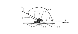
本発明の型成形性とは、貫通孔を有する型に収納し、型を取り去った後でも、貫通孔の形状を維持できる機能である。図19、図20は、型成形性を説明する断面図である。
図19は、型成形性を有する発熱組成物59を説明している。
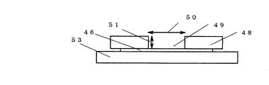
型成形性測定装置62を使用して測定する。支持板53上に非吸水性のプラスチックフィ
ルム56の上に測定板48を置く。次に発熱組成物59をのせ、充填板54と磁石61と
により、測定板48の円柱状貫通孔49に充填し、磁石61を取り去り、測定板48を取
り去った後、円筒状貫通孔49の形状を維持している。図20は、型成形性のない発熱組
成物59を説明している。同様にして、測定板48を取り去った後、円柱状貫通孔49の
形状を維持できず、四方へ崩れている。
The moldability of the present invention is a function capable of maintaining the shape of the through-hole even after being housed in a mold having a through-hole and removing the mold. 19 and 20 are cross-sectional views for explaining moldability.
FIG. 19 illustrates an
Measurement is performed using a mold formability measuring device 62. A
具体的一例として、本発明の発熱体製造方法は、 1)鉄粉、炭素成分、反応促進剤、水を必須成分とし、JIS−P3801の「2種」の濾紙上に載置される内径29mm×高さ20mmの円柱状貫通孔に充填される発熱組成物から前記濾紙に浸透する水又は水溶液の浸透距離を円柱状貫通孔の高さ(mm)で除した値を百分率で表した値である余剰水値0.5〜80の含余剰水発熱組成物を使用し、型孔を有する成形型により、該含余剰水発熱組成物を発熱組成物成形体に成形をする型成形工程及び基材と被覆材に挟まれた該発熱組成物成形体の周縁部を、空間部とシール部を有するシール型によりシールするシール工程を必須工程とする発熱体製造方法であって、 前記型孔に対して、前記空間部は、前記成形型の型孔の開口形状線とそれに対応するシール型の空間部の開口形状線との間の距離である余白距離を前記型孔の高さで除した値である余白値が、0.1〜60である関係を有する発熱体製造方法であり、 本例の場合、該シール型の空間部の高さは、発熱体が製造できれば特に制限はない発熱体製造方法であり、 2)鉄粉、炭素成分、反応促進剤、水を必須成分とし、JIS−P3801の「2種」の濾紙上に載置される内径29mm×高さ20mmの円柱状貫通孔に充填される発熱組成物から前記濾紙に浸透する水又は水溶液の浸透距離を円柱状貫通孔の高さ(mm)で除した値を百分率で表した値である余剰水値0.5〜80の含余剰水発熱組成物を使用し、型孔を有する成形型により、該含余剰水発熱組成物を発熱組成物成形体に成形をする型成形工程及び基材と被覆材に挟まれた該発熱組成物成形体の周縁部を、空間部とシール部を有するシール型によりシールするシール工程を必須工程とする発熱体製造方法であって、 前記型孔に対して、前記空間部は、前記成形型の型孔の開口形状線とそれに対応するシール型の空間部の開口形状線との間の距離である余白距離を前記型孔の高さで除した値である余白値が、0.1〜60であり、且つ、前記空間部の高さを前記型孔の高さで除した値である高さ値が1.1〜150である関係を有する発熱体製造方法であり、 3)成形型の型孔に対して、シール型の空間部は、少なくとも前記成形型の型孔の開口形状線とそれに対応するシール型の空間部の開口形状線との間の距離である余白距離を前記型孔の高さで除した値である余白値が、0.1〜60である関係を持ちながら、前記シール工程において、シールが2個以上複数のシール型で行われ、少なくとも2つのシール部の少なくとも一部が重なるようにシールが行われる発熱体製造方法であり、 4)成形型の型孔に対して、シール型の空間部は、少なくとも前記成形型の型孔の開口形状線とそれに対応するシール型の空間部の開口形状線との間の距離である余白距離を前記型孔の高さで除した値である余白値が、0.1〜60である関係を持ちながら、 前記型成形が回転式の成形型であり、前記シール型が回転式のシール型であり、且つ、 シール型のシール部であるシール面の含余剰水発熱組成物側の端部に隣接させてアールを設け、シール型のシール部であるシール面の断面形状を凹凸形状に形成して模様を設け、該凹凸の少なくとも凸部の角部にアールを設けたシール型により、シールが行われる発熱体製造方法であり、 5)成形型の型孔に対して、シール型の空間部は、少なくとも前記成形型の型孔の開口形状線とそれに対応するシール型の空間部の開口形状線との間の距離である余白距離を前記型孔の高さで除した値である余白値が、0.1〜60である関係を持ちながら、前記シール型の空間内の少なくとも一部が隔離材で覆われている発熱体製造方法であり、 6)前記3)〜5)の何れかに記載の発熱体製造方法において、前記型孔に対して、前記空間部は、前記成形型の型孔の開口形状線とそれに対応するシール型の空間部の開口形状線との間の距離である余白距離を前記型孔の高さで除した値である余白値が、0.1〜60であり、且つ、前記空間部の高さを前記型孔の高さで除した値である高さ値が1.1〜150である関係を有する発熱体製造方法であり、 7)厚さが0.1〜30mmの直線部と先端部を有する板状体で、中空の回転体の成形部に対応する周面と当接し、該当接角度(θt)が95゜〜170゜であるブレードを有する含余剰水発熱組成物供給装置と、厚さ0.1〜10mmの成形部を周面に有する中空の回転体と、前記ブレードの前記周面との当接部(即ち、当接位置)と対応し、前記成形部の前記ブレードと反対側に回転体の回転に沿って移動しないように設けられた磁石と、基材を該中空の回転体に供給するための該基材供給手段、発熱組成物成形体を基材に載置するための載置装置と、該被覆材供給手段とを有し、前記ブレードの周面との当接部(即ち、当接位置)と前記磁石が対応し、移動する前記成形部へ鉄粉を有し、JIS−P3801の「2種」の濾紙上に載置される内径29mm×高さ20mmの円柱状貫通孔に充填される発熱組成物から前記濾紙に浸透する水又は水溶液の浸透距離を円柱状貫通孔の高さ(mm)で除した値を百分率で表した値である、余剰水値が0.5〜80の含余剰水発熱組成物をー回平滑充填することにより、発熱組成物成形体を成形し、更に基材へ積層し、被覆材を該発熱組成物成形体と基材に被覆し、発熱組成物成形体の周縁部をシールする発熱体製造方法であり、 8)厚さ0.1〜10mmの成形部を周面に有する中空の円筒状回転体の内側下部に設けられた、厚さが0.1〜30mmの板状体で、直線部と先端部を有するブレードを有する含余剰水発熱組成物供給装置から、JIS−P3801の「2種」の濾紙上に載置される内径29mm×高さ20mmの円柱状貫通孔に充填される発熱組成物から前記濾紙に浸透する水又は水溶液の浸透距離を円柱状貫通孔の高さ(mm)で除した値を百分率で表した値である余剰水値0.5〜80の含余剰水発熱組成物を供給し、中空の回転体の成形部に対応する周面と当接し、該当接角度(θt)が95゜〜170゜である該ブレードと該ブレードの回転体内周面との当接部と対応し、該成形部の該ブレードと反対側に回転体の回転に沿って移動しないように、該中空の円筒状回転体の外側に設けられた外部固定磁石とにより、該成形部の貫通孔に一回平滑充填し、更に基材供給手段より供給され、無端状ペルトに支持され、回転体の下部に当接するように供給される基材へ、成形された発熱組成物成形体を積層し、更に被覆材供給手段から供給された被覆材を被覆し、発熱組成物成形体の周縁部をシールする発熱体製造方法であり、 9)厚さ0.1〜10mmの成形部を有するシート状型を連接したチェーンコンベア状回転体の内側下部に設けられた、厚さが0.1〜30mmの板状体で、直線部と先端部を有するブレードを有する含余剰水発熱組成物供給装置から、JIS−P3801の「2種」の濾紙上に載置される内径29mm×高さ20mmの円柱状貫通孔に充填される発熱組成物から前記濾紙に浸透する水又は水溶液の浸透距離を円柱状貫通孔の高さ(mm)で除した値を百分率で表した値である余剰水値0.5〜80の含余剰水発熱組成物を、基材供給手段より供給され、無端状ベルトに支持され、回転体の下部のシート状型に当接するように供給される基材に底打ちされたシート状型に供給し、該シート状型の成形部に対応する面と当接し、該当接角度(θt)が95゜〜170゜である該ブレードと該ブレードの回転体内周面との当接部と対応し、該成形部の該ブレードと反対側に回転体の回転に沿って移動しないように、該回転体の外側に設けられた外部固定磁石とにより、該成形部の貫通孔にー回平滑充填し、次に、シート状型を該基材より離説させ、基材上に成形された発熱組成物成形体を積層し、更に被覆材供給手段から供給された被覆材を被覆し、発熱組成物成形体の周縁部をシールする発熱体製造方法であり、 10)厚さ0.1〜10mmの成形部を周面に有する中空の円筒状回転体の外側上部に設けられた、厚さが0.1〜30mmの直線部と先端部を有する板状体で、中空の回転体の成形部に対応する周面と当接し、該当接角度(θt)が95゜〜170゜であるブレードを有する含余剰水発熱組成物供給装置から、鉄粉を有し、JIS−P3801の「2種」の濾紙上に載置される内径29mm×高さ20mmの円柱状貫通孔に充填される発熱組成物から前記濾紙に浸透する水又は水溶液の浸透距離を円柱状貫通孔の高さ(mm)で除した値を百分率で表した値である余剰水値0.5〜80の含余剰水発熱組成物を供給し、中空の回転体の成形部に対応する周面と当接し、該当接角度(θt)が95゜〜170゜である該ブレードと該ブレードの回転体外周面との当接部と対応し、該成形部の該ブレードと反対側に回転体の回転に沿って移動しないように、該中空の回転体の内側に設けられた内部固定磁石とにより、該成形部の貫通孔に一回平滑充填し、更に基材供給手段より供給され、無端状ベルトに支持され、回転体の下部に当接するように供給される基材ヘ、成形された発熱組成物成形体を積層し、更に被覆材供給手段から供給された被覆材を被覆し、発熱組成物成形体の周縁部をシールする発熱体製造方法であり、 11)ブレードの当接角度(θt)が、ブレードの周面又はシート状型面との当接位置の中心点と含余剰水発熱組成物供給装置のブレード用開口部又はブレード取り付け部の立体的中心点とを結ぶ直線と、周面の進行方向と反対方向に伸びる、当接位置の中心点での接線又は面延長線とがなす、含余剰水発熱組成物側の角度であり、95゜〜170゜である、上記7)、8)、9)、10)の何れかの記載に基づく発熱体製造方法であり、 12)前記1)〜6)及び前記7)〜11)からそれぞれ、少なくとも1種ずつ選ばれた組み合わせによる発熱体製造方法である。 また、本発明の発熱組成物成形体の製造方法は、発熱組成物成形体を製造する成形部を有する回転体と、厚さが0.1〜30mmの直線部と先端部を有する板状体で、中空の回転体の成形部に対応する周面と当接し、該当接角度(θt)が95゜〜170゜であるブレードを有する含余剰水発熱組成物供給装置と、前記ブレードの前記周面との当接部と対応し、前記成形部の前記ブレードと反対側に回転体の回転に沿って移動しないように設けられた磁石とにより、前記ブレードと前記磁石が対応し、移動する前記成形部へ鉄粉を有し、余剰水値が0.5〜80の含余剰水発熱組成物を一回平滑充填することにより、発熱組成物成形体を成形する発熱組成物成形体の製造方法であれば制限はない。 即ち、以下の(1)、(2)が一例としてあげられる。(1)該供給装置が回転体の内側下部に設けられたもので、 a.回転体が中空の円筒状回転体で、その周面に設けられた成形部が貫通孔である。 b.回転体がチェーンコンベア状回転体で、成形部がシート状型に設けられた貫通孔で ある。(2)該供給装置が中空の円筒状回転体の外側上部に設けられたもので、 a.回転体の周面に設けられた成形部が貫通孔である。 b.回転体の外周面に設けられた成形部が凹部である。 ただし、含余剰水発熱組成物は、鉄粉を含有し、JIS−P3801の「2種」の濾紙上に載置される内径29mm×高さ20mmの円柱状貫通孔に充填される発熱組成物から前記濾紙に浸透する水又は水溶液の浸透距離を円柱状貫通孔の高さ(mm)で除した値を百分率で表した値である余剰水値が0.5〜80であり、本発明の成形部は、少なくとも貫通孔又は凹部から選ばれた1種である。 以上のように、本発明の発熱体製造方法は、前記発熱体製造方法の1)〜12)及び前記発熱組成物成形体の製造方法から選ばれた少なくとも一種を使用した発熱体製造方法である。特に、前記余白値が、0.1〜60であり、且つ、前記高さ値が1.1〜150である関係を有する前記成形型と前記シール型を使用した発熱体の製造方法と発熱組成物成形体の製造方法を組み合わせた発熱体製造方法が好ましい。
As a specific example, the heating element manufacturing method of the present invention is as follows. 1) Iron powder, carbon component, reaction accelerator, water are essential components, and an inner diameter of 29 mm placed on “two types” filter paper of JIS-P3801. X A value obtained by dividing the permeation distance of water or an aqueous solution penetrating into the filter paper from the exothermic composition filled in the cylindrical through-hole having a height of 20 mm by the height (mm) of the cylindrical through-hole. A molding process and a base for using a surplus water exothermic composition having a surplus water value of 0.5 to 80 and molding the surplus water exothermic composition into a exothermic composition molded body with a mold having a mold hole. A heating element manufacturing method comprising a sealing step of sealing a peripheral portion of the exothermic composition molded body sandwiched between a material and a covering material with a sealing mold having a space portion and a sealing portion, On the other hand, the space portion includes the opening shape line of the mold hole of the mold and the A heating element having a relationship in which a margin value, which is a value obtained by dividing a margin distance, which is a distance from the opening shape line of the space portion of the seal mold corresponding to, by the height of the mold hole, is 0.1-60. In the case of this example, the height of the space part of the seal type is not particularly limited as long as the heating element can be manufactured. 2) Iron powder, carbon component, reaction accelerator, water Of water or aqueous solution that permeates the filter paper from the exothermic composition filled in the cylindrical through-hole having an inner diameter of 29 mm × height of 20 mm placed on “two types” filter paper of JIS-P3801 Using a surplus water exothermic composition having an excess water value of 0.5 to 80, which is a value obtained by dividing the distance by the height (mm) of the cylindrical through hole as a percentage, and depending on the mold having the mold hole A mold forming step of molding the excess water exothermic composition into a exothermic composition molded body, and a substrate; A heating element manufacturing method comprising a sealing step of sealing a peripheral portion of the exothermic composition molded body sandwiched between coating materials with a sealing mold having a space portion and a sealing portion. The space portion is a value obtained by dividing a margin distance, which is a distance between the opening shape line of the mold hole of the mold and the opening shape line of the space portion of the seal mold corresponding thereto, by the height of the mold hole. A heating element having a relationship that a certain margin value is 0.1 to 60 and a height value obtained by dividing a height of the space portion by a height of the mold hole is 1.1 to 150. 3) With respect to the mold hole of the mold, the space part of the seal mold is at least between the opening shape line of the mold hole of the mold and the corresponding opening shape line of the space part of the seal mold. The margin value, which is a value obtained by dividing the margin distance, which is the distance between the two, by the height of the mold hole is 0.1 to 60 A heating element manufacturing method in which, in the sealing step, the sealing is performed with a plurality of seal dies, and the sealing is performed so that at least a part of at least two seal portions overlap each other in the sealing step. 4) Molding With respect to the mold hole of the mold, the space part of the seal mold has at least a margin distance that is a distance between the opening shape line of the mold hole of the mold and the opening shape line of the space part of the seal mold corresponding thereto. While the margin value which is a value divided by the height of the mold hole has a relationship of 0.1 to 60, the mold molding is a rotary mold, and the seal mold is a rotary seal mold. In addition, a radius is provided adjacent to the end of the seal surface that is the seal-type seal portion on the excess water heating composition side, and the cross-sectional shape of the seal surface that is the seal-type seal portion is formed in an uneven shape. A pattern is provided, and at least convex of the irregularities 5) A heating element manufacturing method in which sealing is performed by a sealing die provided with rounded corners. 5) The space of the sealing die is at least of the die hole of the molding die. A margin value that is a value obtained by dividing a margin distance, which is a distance between the opening shape line and the opening shape line of the seal-type space portion corresponding thereto, by the height of the mold hole is 0.1 to 60 6) The heating element manufacturing method according to any one of 3) to 5) above, wherein at least a part of the seal-type space is covered with a separator. With respect to the mold hole, the space portion has a margin distance that is a distance between the opening shape line of the mold hole of the mold and the opening shape line of the space portion of the seal mold corresponding to the height of the mold hole. The margin value which is a value divided by 0.1 is 0.1 to 60, and the height of the space portion is A heating element manufacturing method having a relationship in which a height value, which is a value divided by the height of the recording hole, is 1.1 to 150, and 7) a straight portion and a tip portion having a thickness of 0.1 to 30 mm. A surplus water heating composition supply device having a blade that has a plate-like body that is in contact with a peripheral surface corresponding to a molding part of a hollow rotating body and whose contact angle (θt) is 95 ° to 170 °; Corresponds to the contact portion (that is, the contact position) of the hollow rotating body having a molded portion with a thickness of 0.1 to 10 mm on the peripheral surface and the peripheral surface of the blade, opposite to the blade of the molded portion A magnet provided so as not to move along the rotation of the rotating body, the base material supplying means for supplying the base material to the hollow rotating body, and the exothermic composition molded body are placed on the base material. And a covering material supply means, and a contact portion (that is, a contact position) with the peripheral surface of the blade and the front The recording magnet corresponds to the heat generating part that has iron powder in the moving molded part and is filled in a cylindrical through-hole having an inner diameter of 29 mm and a height of 20 mm, which is placed on “
前記成形型の型孔は、含余剰水発熱組成物を成形し、発熱組成物成形体を形成するために型に設けられた貫通孔や凹部等である。 The mold hole of the molding die is a through-hole, a recess, or the like provided in the mold for molding the excess water exothermic composition and forming the exothermic composition molded body.
本発明の発熱体製造方法を、A.B.C.D.E.F.G.を一例として挙げ、詳細に説明する。
A. 本発明の一つの発熱体製造方法は、含余剰水発熱組成物を使用し、型成形をする型成形工程とシールをするシール工程を必須工程とする発熱体製造方法であって、型孔を有する成形型とシール領域であるシール部と非シール領域である空間部を有するシール型を用いて行われ、前記成形型の型孔の開口形状線とそれに対応するシール型の空間部の開口形状線との間の距離である余白距離を前記型孔の高さで除した値である余白値が、0.1〜60である関係を有する発熱体製造方法である。
本発熱体製造方法では、基材上に積層された、含余剰水発熱組成物を成形した発熱組成物成形体が被覆材に被覆され、該発熱組成物成形体の周縁部の基材と被覆材をシールすることにより、発熱体を製造する方法であり、シール進行方向において、型孔を有する成形型の型孔の開口形状線は、シール領域であるシール部と非シール領域である空間部を有するシール型の空間部の開口形状線の内側に含まれ、型孔の開口形状線と空間部の開口形状線は接したり、重なったり、交差することはない。更に、前記成形型の型孔とそれに対応するシール型の空間部が、前記余白値が、0.1〜60である関係を有するために、基材と被覆材との間の含余剰水発熱組成物を成形した発熱組成物成形体の周縁部を歩留まり良くシールすることができる。 本例の場合、該シール型の空間部の高さは、発熱体が製造できれば特に制限はない発熱体製造方法である。
The method for producing a heating element of the present invention comprises: B. C. D. E. F. G. Will be described in detail as an example.
A. One heating element manufacturing method of the present invention is a heating element manufacturing method that uses a surplus water heating composition and has a molding step for molding and a sealing step for sealing as essential steps. The molding die having a sealing part having a sealing part which is a sealing region and a space part which is a non-sealing region, and the opening shape line of the mold hole of the molding die and the corresponding opening shape of the space part of the sealing die It is a heating element manufacturing method which has the relationship that the margin value which is the value which remove | divided the margin distance which is the distance between lines with the height of the said mold hole is 0.1-60.
In this heating element manufacturing method, the exothermic composition molded body obtained by molding the surplus water exothermic composition laminated on the base material is coated with the coating material, and the base material and the coating on the peripheral portion of the exothermic composition molded body are coated. This is a method for producing a heating element by sealing a material, and the opening shape line of the mold hole of the molding die having the mold hole in the direction of the seal progress is a seal part that is a seal area and a space part that is a non-seal area The opening shape line of the space part of the seal mold having the inside of the mold part is not in contact with, overlapping with, or intersecting with the opening shape line of the mold hole. Furthermore, because the mold hole of the mold and the space portion of the seal mold corresponding to the mold hole have a relationship that the margin value is 0.1 to 60, the excess water heat generation between the base material and the covering material The peripheral portion of the exothermic composition molded body obtained by molding the composition can be sealed with a high yield. In the case of this example, the height of the space portion of the seal mold is not particularly limited as long as the heating element can be manufactured.
本発明の余白値について説明する。
余白値は、余白距離を 成形型の型孔の高さで除した値である。
余白距離は、成形型の型孔の開口形状線で形成される型孔の開口面の中心点と対応するシール型の空間部の開口形状線で形成される空間部の開口面の中心点を重ね、該中心点を通る直線と交差する、該型孔の開口形状線と該空間部の開口形状線との間の距離、即ち、該型孔の開口形状線とそれに対応する該空間部の開口形状線との間の距離である。開口形状線は、成形型の型孔の開口部での該型孔の形状、又は該形状を描く線であり、シール型の空間部の開口部での該空間部の形状、又は該形状を描く線である。
ただし、前記成形型の型孔の開口面の中心点とシール型の空間部の開口面の中心点を重ねた状態は、前記開口面を形成している、双方の開口形状線が接触もせず、重ならず、交わらず、前記シール型の空間部の開口面内に前記成形型の型孔の開口面が内包されている状態である。また、余白距値は規定値以内であれば制限はないが、成形型の型孔の高さが高い程、余白値を大きくすることが好ましい。
即ち、余白距離は下記の式より求められる。
W= w/m
W :余白値
m :成形型の型孔の高さ
w :余白距離
ただし、
1)成形型の型孔の開口形状が、矩形等の直線で形成される場合、
開口形状線の角部を構成する各辺の延長線が交差する点を角部としても
よい。
2)成形型の型孔及び/又はシール型の空間部が貫通孔の場合、
貫通孔の出口側の開口形状線を採用する。
3)成形型の型孔の高さは該型孔の高さが一様でない場合は、型孔の最大の高さ を採用することが好ましい。
4)余白値の範囲以内であれば、開口形状線上の各点での余白距離は、必ずしも 一定である必要はない。成形型の型孔の開口形状とシール型の空間部の開口 形状は、相似形の場合もあるし、非相似形の場合もある。
5)中心点が複数ある形状の場合は一番近い中心点を使用する。
The margin value of the present invention will be described.
The margin value is a value obtained by dividing the margin distance by the height of the mold hole of the mold.
The margin distance is defined as the center point of the opening surface of the space portion formed by the opening shape line of the space portion of the seal mold corresponding to the center point of the opening surface of the mold hole formed by the opening shape line of the mold hole of the mold. The distance between the opening shape line of the mold hole and the opening shape line of the space portion, which intersects the straight line passing through the center point, that is, the opening shape line of the mold hole and the space portion corresponding thereto The distance between the opening shape line. The opening shape line is a line drawing the shape of the mold hole at the opening of the mold hole of the mold or the shape, and the shape of the space at the opening of the space of the seal mold, or the shape. It is a line to draw.
However, when the center point of the opening surface of the mold hole of the molding die and the center point of the opening surface of the space portion of the seal mold are overlapped, the opening shape lines of both sides do not contact each other. In this state, the opening surface of the mold hole of the molding die is included in the opening surface of the space portion of the seal die without overlapping. The margin distance value is not limited as long as it is within a specified value, but it is preferable to increase the margin value as the mold hole height of the mold is higher.
That is, the margin distance is obtained from the following formula.
W = w / m
W: Margin value
m: mold hole height of the mold
w: margin distance
However,
1) When the opening shape of the mold hole of the mold is a straight line such as a rectangle,
The point where the extended line of each side that forms the corner of the opening shape line intersects
Good.
2) When the mold hole of the mold and / or the space of the seal mold is a through hole,
An opening shape line on the outlet side of the through hole is employed.
3) When the height of the mold hole of the mold is not uniform, it is preferable to adopt the maximum height of the mold hole.
4) If it is within the margin value range, the margin distance at each point on the opening shape line does not necessarily have to be constant. The opening shape of the mold hole of the molding die and the opening shape of the space portion of the seal die may be similar or non-similar.
5) If the shape has a plurality of center points, use the closest center point.
本発明の余白値につて図21〜図24を使用して説明する。 The margin value of the present invention will be described with reference to FIGS.
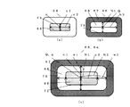
図21(a)は、成形型の一例を示す平面図である。
成形型の型孔の開口部での該型孔の形状、又は該形状を描く線である開口形状線75が長方形の、1個の型孔65が設けられた成形型64である。qは型孔の中心点である。
図21(b)は、成形型の他の一例を示す平面図である。
成形型の型孔の開口部での該型孔の形状、又は該形状を描く線である開口形状線75が長方形の、6個の型孔65、65、65、65、65、65が設けられた成形型64である。qは型孔の中心点である。
FIG. 21A is a plan view showing an example of a mold.
The shape of the mold hole at the opening of the mold hole of the mold, or the
FIG. 21B is a plan view showing another example of the mold.
Six mold holes 65, 65, 65, 65, 65, 65 are provided in which the shape of the mold hole at the opening of the mold hole of the molding die or the
図22(a)は、シール型の一例を示す平面図である。
シール型の空間部の開口部での該空間部の形状、又は該形状を描く線である開口形状線76が長方形の、1個の空間部68が設けられたシール型66である。該空間部68はシール部67に囲まれている。Qは空間部の中心点である。
図22(b)は、シール型の他の一例を示す平面図である。
シール型の空間部の開口部での該空間部の形状、又は該形状を描く線である開口形状線76が長方形の、6個の空間部68、68、68、68、68、68が設けられたシール型66である。該空間部68はシール部67に囲まれている。Qは空間部の中心点である。
FIG. 22A is a plan view showing an example of a seal type.
The shape of the space portion at the opening portion of the seal-type space portion or the
FIG. 22B is a plan view showing another example of the seal type.
Six
図23は、成形型の型孔とシール型の空間部を合わせた一例を示す平面模式図である.
シール型の空間部の開口部での該空間部の形状、又は該形状を描く線である開口形状線76が長方形の、6個の空間部68、68、68、68、68、68を有するシール型66が、各開口形状線76が長方形の空間部68に、成形型64の各開口形状線75が長方形の型孔65を余裕を持って収納している。成形型の型孔65とシール型の空間部68との間において、該空間部68は、該型孔65に対して余白値が0.1〜60である関係を有する。本例では、シール型の空間部はシール部67に囲まれているが、縦シール、横シールと分けて、シールをする場合は、空間部68は、必ずしもシール部67に囲まれている必要はない。Qは空間部の中心点である。qは型孔の中心点である。
FIG. 23 is a schematic plan view showing an example in which the mold hole of the mold and the space of the seal mold are combined.
The shape of the space portion at the opening portion of the seal-type space portion or the
図24(a)は、成形型の他の一例を示す平面図である。
成形型64の中央部に開口形状線75が長方形の型孔65が設けられている。n1は短手方向において、成形型の型孔65の中心点qから開口形状線75までの長さであり、n2は長手方向において、成形型の型孔65の中心点qから開口形状線75までの長さである。
図24(b)は、シール型の他の一例を示す平面図である。
シール型66の中央部に開口形状線76が長方形の空間部68が、その周りにシール部67が設けられている。
N1は短手方向において、シール型の空間部68の中心点Qから開口形状線76までの長さであり、N2は長手方向において、シール型の空間部68の中心点Qから開口形状線76までの長さである。
図24(c)は、型孔と空間部の重ねあわせを示す平面模式図である。
成形型64の、長方形の型孔65の開口形状線75から外側に余白距離w1、w2を隔てたところに、シール型66の、長方形の空間部68の開口形状線76がある。短手方向において、中心点Qから開口形状線76までの空間部の長さN1は、成形型の型孔の中心点qから開口形状線75までの長さn1に、余白距離w1を加えた長さであり、長手方向において、中心点Qからの開口形状線76までの長さN2は、成形型の型孔の中心点qから開口形状線75までの長さn2に、余白距離w2を加えた長さであり、それぞれが余白値0.1〜60を満足している。シール型の空間部の長方形の角部は各辺の延長線が交差する点とし、角部にアールを設け、角部をアール状にしている。
したがって、本例では、型孔65の形状のコピー形状を有する発熱組成物成形体とシール部67の端部との間に距離が保てるので、シールへの影響はない。Qは空間部の中心点であり、qは型孔の中心点である。
前記成形型の型孔の開口面の中心点とシール型の空間部の開口面の中心点を重ねた状態は、前記開口面を形成している、双方の開口形状線が接触もせず、重ならず、交わらず、シール型の空間部の開口面内に前記成形型の型孔の開口面が内包されている状態である。
ここで、該開口形状線は、成形型の型孔の開口部又は開口面での該型孔の形状、又は該形状を描く線であり、シール型の空間部の開口部又は開口面での該空間部の形状、又は該形状を描く線である。
FIG. 24A is a plan view showing another example of the mold.
A mold hole 65 having an
FIG. 24B is a plan view showing another example of the seal type.
A
N1 is the length from the center point Q of the seal-
FIG. 24C is a schematic plan view showing the overlapping of the mold cavity and the space portion.
An
Therefore, in this example, since a distance can be maintained between the exothermic composition molded body having a copy shape of the shape of the mold hole 65 and the end portion of the
The state in which the center point of the opening surface of the mold hole of the mold is overlapped with the center point of the opening surface of the space portion of the seal mold is such that both opening shape lines forming the opening surface do not come into contact with each other. In other words, the opening surface of the mold hole of the mold is included in the opening surface of the space portion of the seal mold.
Here, the opening shape line is the shape of the mold hole at the opening or opening surface of the mold hole of the molding die, or a line describing the shape, and the line at the opening or opening surface of the space portion of the seal mold. The shape of the space portion or a line that draws the shape.
B. 本発明の一つの発熱体製造方法は、含余剰水発熱組成物を使用し、型成形をする型成形工程とシールをするシール工程を必須工程とする発熱体製造方法であって、
型孔を有する成形型とシール領域であるシール部と非シール領域である空間部を有するシール型を用いて行われ、前記空間部が、前記型孔に対して、前記成形型の型孔の開口形状線とそれに対応するシール型の空間部の開口形状線との間の距離である余白距離を前記型孔の高さで除した値である余白値が、0.1〜60であり、且つ、前記空間部の高さを前記型孔の高さで除した値である高さ値が1.1〜150である関係を有する発熱体製造方法である。
本発熱体製造方法では、基材上に積層された、含余剰水発熱組成物を成形した発熱組成物成形体が被覆材に被覆され、該発熱組成物成形体の周縁部の基材と被覆材をシールすることにより、発熱体を製造する方法であり、シール進行方向において、型孔を有する成形型の型孔の開口形状線は、シール領域であるシール部と非シール領域である空間部を有するシール型の空間部の開口形状線の内側に含まれ、型孔の開口形状線と空間部の開口形状線は接したり、重なったり、交差することはない。更に、前記成形型の型孔とそれに対応するシール型の空間部が、前記余白値が、0.1〜60であり、且つ、前記高さ値が1.1〜150である関係を有するために、基材と被覆材との間の含余剰水発熱組成物を成形した発熱組成物成形体の周縁部を歩留まり良くシールすることができる。
B. One heating element manufacturing method of the present invention is a heating element manufacturing method that uses a surplus water heating composition, and has a molding step for molding and a sealing step for sealing as essential steps,
A mold having a mold hole and a seal mold having a seal portion which is a seal region and a space portion which is a non-seal region, and the space portion of the mold hole of the mold with respect to the mold hole. The margin value, which is a value obtained by dividing the margin distance, which is the distance between the opening shape line and the opening shape line of the seal-type space portion corresponding to the opening shape line, by the height of the mold hole is 0.1 to 60, And it is a heat generating body manufacturing method which has the relationship whose height value which is the value which remove | divided the height of the said space part with the height of the said mold hole is 1.1-150.
In this heating element manufacturing method, the exothermic composition molded body obtained by molding the surplus water exothermic composition laminated on the base material is coated with the coating material, and the base material and the coating on the peripheral portion of the exothermic composition molded body are coated. This is a method for producing a heating element by sealing a material, and the opening shape line of the mold hole of the molding die having the mold hole in the direction of the seal progress is a seal part that is a seal area and a space part that is a non-seal area The opening shape line of the space part of the seal mold having the inside of the mold part is not in contact with, overlapping with, or intersecting with the opening shape line of the mold hole. Further, the mold hole of the mold and the corresponding space of the seal mold have a relationship that the margin value is 0.1 to 60 and the height value is 1.1 to 150. In addition, it is possible to seal the peripheral portion of the exothermic composition molded body obtained by molding the excess water exothermic composition between the base material and the covering material with a high yield.
本発明の高さ値について説明する。
本発明の高さ値は、空間部を有するシール型の空間部の高さを規定する値である。
発熱体の発熱部の配置位置に対応した該型孔の断面図の形状において、前記高さ値は、成形型の型孔の高さとそれに対応したシール型の空間部の高さとの関係を示す値であり、シール型の空間部の高さを成形型の型孔の高さで除した値である。
該高さ値において、
前記シール型の数及びその空間部の数に関係なく、それぞれの空間部の高さは独自の高さ値を有する。
また、前記シール型の空間部の高さは必ずしも一様である必要はない。
また、前記成形型の型孔の高さが一様でない場合は、少なくとも成形型の型孔の高さに対応するシール型の空間部の高さは、成形型の型孔の高さより高く保つことが好ましい。 また、前記成形型の型孔の高さは、型孔の最大の高さを採用してもよい。
また、前記成形型の型孔の最大の高さをふまえて、シール型の空間部の高さを決めてもよい。
場合分けをすれば、
1. 一つの空間部を有するシール型が一つの場合、
H = j/m
H : シール型の空間部の高さ値
j : シール型の空間部の高さ
m : 成形型の型孔の高さ
2. 複数の空間部を有するシール型が一つの場合、
各空間部毎に、下記を適用する。
H = j/m
H : シール型の個別の空間部の高さ値
j : シール型の個別の空間部の高さ
m : 成形型の型孔の高さ
3. 一つの空間部を有するシール型が一対の場合、
各空間部毎に、下記を適用する。
H = j/m 、且つ、 H = k/m
H : 各シール型の空間部の高さ値
j : 一方のシール型の空間部の高さ
k : 他方のシール型の空間部の高さ
m : 成形型の型孔の高さ
4. 複数の空間部を有するシール型が一対の場合、
各空間部毎に、下記を適用する。
H = j/m 、且つ、 H = k/m
H : 各シール型の各空間部の高さ値
j : 一方のシール型の個別の空間部の高さ
k : 他方のシール型の個別の空間部の高さ
m : 成形型の型孔の高さ
ただし、一対のシール型において、シールができれば、シール型の組み合わせに制限はなく、材質、形状等、その組み合わせにも制限はない。
また、加熱の有無も制限はなく、適宜選択をすればよい。1)双方とも加熱されていないシール型、2)、一方のみが加熱されたシール型、3)双方とも加熱されたシール型等が一例としてあげられる。
また、 2個以上複数の空間部を有する成形型、シール型の場合は、前記同様とし、各空間部に対して前記1)2)3)に記載の何れかの事項が適用できる。
また、被シール体が直接、シール型の空間部に接触しないように、該空間部内(凹部内又は貫通孔内)の少なくとも一部にスポンジ状体、断熱材等の隔離材を設けることは好ましい。その場合はシール時に発熱組成物成形体の崩れ等が起こっても、シールに影響ないように隔離材を配置する。その場合、該空間部の内奥部をえぐるようにしてもよい。
The height value of the present invention will be described.
The height value of the present invention is a value that defines the height of the seal-type space portion having the space portion.
In the cross-sectional shape of the mold hole corresponding to the arrangement position of the heat generating portion of the heat generating element, the height value indicates the relationship between the height of the mold hole of the mold and the height of the space portion of the seal mold corresponding thereto. It is a value obtained by dividing the height of the space portion of the seal mold by the height of the mold hole of the mold.
In the height value,
Regardless of the number of the sealing molds and the number of the space portions, the height of each space portion has a unique height value.
Further, the height of the seal-type space portion is not necessarily uniform.
Further, when the height of the mold hole of the mold is not uniform, at least the height of the space portion of the seal mold corresponding to the height of the mold hole of the mold is kept higher than the height of the mold hole of the mold. It is preferable. Further, the maximum height of the mold hole may be adopted as the height of the mold hole of the mold.
Further, the height of the space portion of the seal mold may be determined based on the maximum height of the mold hole of the mold.
If divided into cases,
1. When there is one seal mold with one space,
H = j / m
H: Height value of seal-type space
j: Height of seal-type space
m: mold hole height of the mold
2. If there is one seal mold with multiple spaces,
The following applies for each space.
H = j / m
H: Height value of individual space of seal type
j: Height of individual space part of seal type
m: mold hole height of the mold
3. When a pair of seal molds having one space part is
The following applies for each space.
H = j / m and H = k / m
H: Height value of the space of each seal type
j: Height of one seal-type space
k: the height of the space of the other seal type
m: mold hole height of the mold
4). When a pair of seal molds having a plurality of space portions,
The following applies for each space.
H = j / m and H = k / m
H: Height value of each space part of each seal type
j: Height of the individual space of one seal type
k: Height of the individual space of the other seal type
m: mold hole height of the mold
However, in the pair of seal molds, the combination of the seal molds is not limited as long as the seal can be made, and the combination of materials, shapes, etc. is not limited.
Moreover, there is no restriction | limiting in the presence or absence of heating, What is necessary is just to select suitably. Examples include 1) a seal type in which both are not heated, 2), a seal type in which only one is heated, and 3) a seal type in which both are heated.
Further, in the case of a molding die or a seal die having two or more space portions, the same as described above, and any of the matters described in 1), 2) and 3) can be applied to each space portion.
Further, it is preferable to provide a separating material such as a sponge-like body or a heat insulating material in at least a part of the space (inside the recess or in the through hole) so that the sealed body does not directly contact the seal-type space. . In that case, a separating material is arranged so that the seal is not affected even when the exothermic composition molded body collapses during sealing. In that case, you may make it go in the inner back part of this space part.
本発明の高さ値を図25〜図29を使用して説明する。 The height value of the present invention will be described with reference to FIGS.
図25(a)は、成形型の他の一例を示す断面図である。
型孔65が貫通孔で、下側に出口となる開口部77を有する成形型64であり、 型孔65の高さはmで示されている。
図25(b)は、成形型の他の一例を示す断面図である。
型孔65が凹部で、下側に開口部77を有する成形型64であり、型孔65の高さはmで示されている。
FIG. 25A is a cross-sectional view showing another example of the mold.
The mold hole 65 is a through-hole, and is a forming
FIG. 25B is a cross-sectional view showing another example of the mold.
The mold hole 65 is a concave part and is a
図26は、シール型の他の一例を示す断面図である。
二つのシール型66、66を使用し、シール部67、67を向かいあわせ、一対で使用した例である。一方のシール型66の個別空間部68の高さjと他の一方のシール型の個別空間部68の高さkが開口部78、78を向かい合せている。
FIG. 26 is a cross-sectional view showing another example of a seal type.
In this example, two
図27は、高さ値を説明する断面模式図である。
シール型66、66のシール部67、67を向かいあわせ、個別空間部68、68内に成形型の型孔65を取り込んでいる。
成形型の型孔65の高さmと、各シール型の空間部68、68のそれぞれの高さj、高さkとの間には、高さ値が、1.1〜150であるとの関係が保たれているので、一対のシール型の空間部68、68内に成形型の型孔65即ち、型孔サイズの発熱組成物成形体を余裕をもって収納できる。
FIG. 27 is a schematic cross-sectional view illustrating the height value.
The
Between the height m of the mold hole 65 of the mold and the heights j and k of the
図28は、シールロールの空間部と包材間に挟まれた発熱組成物成形体との関係の一部拡大の一例を示す断面模式図である。
シール型66、66のシール部67、67を向かいあわせ、該空間部68、68は、高さ値が、1.1〜150であるので、高さに関しては基材23と被覆材22に挟まれた発熱組成物成形体37は余裕を持ってシールロールの空間部68、68に収納されている。
シール型66、66の空間部68、68は、余白値が0.1〜60とあいまっているので、発熱組成物成形体37の崩壊破片によるシールへの影響はない。
FIG. 28 is a schematic cross-sectional view showing an example of a partial enlargement of the relationship between the space portion of the seal roll and the exothermic composition molded body sandwiched between the packaging materials.
Since the
Since the
また、図29(a)は、本発明のシール方向における成形型の型孔とシール型の空間部の位置関係の一例を示す説明平面図である。
シール方向である包材の移動方向Gにおける成形型の型孔65と四方のシールを行うシール部67を有する、四方シールのシール型の空間部68の軌跡の位置関係示す。該型孔65と該空間部68は同期(シンクロ)しており、該型孔65の軌跡は、空間部68の軌跡内に有り、該型孔65の軌跡は、空間部68の軌跡と接することもないし、重なりもせず、交差することもない。
図29(b)は、本発明のシール方向における成形型の型孔とシール型の空間部の位置関係の他の一例を示す説明平面図である。
シール方向である包材の移動方向Gにおける成形型の型孔65の軌跡と横のシールを行うシール部67を有する二方シールのシール型の空間部68の軌跡の位置関係示す。該型孔65と該空間部68は同期(シンクロ)しており、該型孔65の軌跡は、空間部68の軌跡内に有り、該型孔65の軌跡は、空間部68の軌跡と接することもないし、重なりもせず、交差することもない。
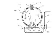
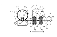
図30は、本発明の発熱体の製造方法の他の一例を示す説明断面図である。
図を使用して、本発明の発熱組成物成形体の製造工程とシール工程とからなる発熱体の製造方法を説明する。Gは回転進行方向、又は移動方向である。
発熱体製造装置15における発熱組成物成形体の製造工程は、
貫通孔である型孔65からなる、複数個の成形部16を周面に有する中空の円筒状回転体19の内側下部に、本発明の含余剰水発熱組成物供給装置1が設けられ、該含余剰水発熱組成物供給装置1と外部固定磁石26により、含余剰水発熱組成物36を該型孔65に一回平滑充填し、搬送されてきた基材23上に発熱組成物成形体37を積層する。更に基材23上に積層された発熱組成物成形体37はシール工程へ搬送される。
シール工程では、搬送されてきた該発熱組成物成形体37が積層された基材23に被覆材22が被覆され、更に、余白値が0.1〜60であり、且つ、高さ値が1.1〜150である関係を有する空間部(非シール領域)68を有する第一シールロール70に搬送される。基材23と被覆材22に挟まれた発熱組成物成形体37は該空間部68内に取り込まれながら、発熱組成物成形体37の周縁部をヒートシールされ、発熱体が連接した連続発熱体74が形成される。更に第二シールロール71に搬送され、所定のヒートシールがされる。
次に、カット工程に送られ、カットロール73により、個々の発熱体60にカットされる。尚、中空の円筒状回転体19の成形部16等の含余剰水発熱組成物36の残留物等はクリーナー30により、除去される。
本発明の含余剰水発熱組成物36を成形した発熱組成物成形体37は基本的には水により発熱組成物の各成分が連結されているので、シール時に被覆材22の不要な摩擦等により、形崩れする虞がある。この型崩れにより飛散する発熱組成物成形体37の破片はシール領域に浸入し、シール切れの原因になる。本発明のシールロール70、71の空間部68は、前記型孔65に対し、余白値が0.1〜60であり、且つ、高さ値が1.1〜150である関係を有しており、余裕を持って該空間部68に、基材23と被覆材22に挟まれた発熱組成物成形体37を取り込めるので、該型孔65のコピーである発熱組成物成形体37と該シール部67の端部との間に距離が保て、該発熱組成物成形体37がシール崩れすることなくシールができる。万が一、若干崩れても、シール切れ等の発熱体のシール部67への影響はない。
また、第二シールロール71とカットロール73の間にならしロール72を設け、シール工程より搬送されてきた、発熱体が連接した連続発熱体74の表面をならし、平坦化して、カット工程に搬送してもよい。
また、シールを圧着シールにする場合は、メルトブロー法等に基づく粘着剤塗布装置等の接着層塗布装置69により、被覆材22に網目状粘着剤層等からなる接着層を設け、基材23上に積層された発熱組成物成形体37を被覆すると共に第一シールロール70にて、圧着シールをしてもよい。この場合、第一シールロール70及び第二シールロール71は加熱されている必要はなく、加熱するかどうかは、適宜選択すればよい。
また、図示はしないが、メルトブロー法等に基づく粘着剤塗布装置等の接着層塗布装置とセパレータ設置装置を第二シールロールとカットロールの間に設け、シールされた連続発熱体に該接着層塗布装置により、網目状粘着剤層等からなる粘着剤層を設け、更にセパレータを積層し、更にカットロール搬送し、カットすれば、発熱体の通気性側に網目状粘着剤層を設けた発熱体や発熱体の非通気性側に粘着剤層を設けた発熱体が製造、提供できる。
また、発熱組成物成形体製造装置19からカットロール73までの全工程にわたり、回転するものはシンクロ化されている。
FIG. 29 (a) is an explanatory plan view showing an example of the positional relationship between the mold hole of the mold and the space of the seal mold in the sealing direction of the present invention.
The positional relationship of the locus | trajectory of the
FIG. 29B is an explanatory plan view showing another example of the positional relationship between the mold hole of the molding die and the space portion of the seal die in the sealing direction of the present invention.
The positional relationship between the locus of the mold hole 65 of the molding die and the locus of the
FIG. 30 is an explanatory cross-sectional view showing another example of the method for manufacturing a heating element of the present invention.
The manufacturing method of the heat generating body which consists of the manufacturing process of the exothermic composition molded object of this invention and a sealing process is demonstrated using figures. G is the direction of rotation or movement.
The manufacturing process of the exothermic composition molded body in the heating
The surplus water exothermic
In the sealing step, the
Next, it is sent to the cutting process, and is cut into
Since the exothermic composition molded
Further, a leveling roll 72 is provided between the second seal roll 71 and the
When the seal is a pressure-bonding seal, an adhesive layer made of a mesh-like pressure-sensitive adhesive layer or the like is provided on the covering
Although not shown, an adhesive layer coating device such as an adhesive coating device based on a melt blow method and the like and a separator installation device are provided between the second seal roll and the cut roll, and the adhesive layer is applied to the sealed continuous heating element. A heating element provided with a network-like pressure-sensitive adhesive layer on the breathable side of the heating element by providing a pressure-sensitive adhesive layer composed of a network-like pressure-sensitive adhesive layer, etc. In addition, a heating element having an adhesive layer on the non-breathable side of the heating element can be manufactured and provided.
In addition, the rotating components are synchronized throughout the entire process from the exothermic composition molded
図30に示すシール方法は、第一シ−ルロール70と第二シールロール71とにより、発熱組成物成形体37の周縁部をシールするものであるが、まず、第一のシールロール70により、基材23と被覆材22に挟持された発熱組成物成形体37の周縁部がシールされ、第一シ−ルロール70のシール部67により第一シール部が形成される。次に、第二シールロール71により、第一シール部の上から第一シール部よりも幅を狭く、発熱組成物成形体37の周縁部より外側に位置する第一シール部の外周側をシールし、第二シールロール71のシール部67により第二シール部が形成される。このようにして重ねてシールすることにより、シールの強度を高めることができる。
また、第二のシール型である第二シールロール71のシール部67のシール幅(第二シール幅)は、第一のシール型である第一シールロール70のシール部67のシール幅(第一シール幅)にすべて重り、重複シールであってもよい。
尚、重ねてシールする、シール領域については必ずしも全周とする必要はなく、強度を高める必要がある部分のみ重ねてシールするものであってもよく、例えば、発熱体の上下端部のみ重ねてシールし、発熱体のシール部を形成するようにしてもよい。
The sealing method shown in FIG. 30 is to seal the peripheral edge portion of the exothermic composition molded
Further, the seal width (second seal width) of the
In addition, it is not always necessary to have the entire circumference of the seal area to be sealed, and only the portion that needs to be increased in strength may be overlapped and sealed. For example, only the upper and lower ends of the heating element are overlapped. Sealing may be performed to form a seal portion of the heating element.
また、シールを複数回に分ける場合、第一のシール型(第一シールロール等)に空気排出溝を設けるようにすれば、第一のシール型(第一シールロール等)によってシールされる外に、空気を抜くことができる。尚、この場合、空気排出溝によってシールされなかった部分は、第二のシール型(第二シールロール等)によってシールされる。また、シール型において、空気排出溝を形成する箇所は特に制限されるものでない。 In addition, when the seal is divided into a plurality of times, if the air discharge groove is provided in the first seal mold (first seal roll, etc.), the outside sealed by the first seal mold (first seal roll, etc.) In addition, the air can be extracted. In this case, the portion that is not sealed by the air discharge groove is sealed by the second seal mold (second seal roll or the like). Further, in the seal mold, the location where the air discharge groove is formed is not particularly limited.
また、第一シールロール70は、余白値が0.1〜60であり、高さ値が、1.1〜150である空間部(凹部)68が、周方向に所定間隔で配置されており、該空間部(凹部)68を除く部分をシール部67とし、一対のシールロール間に、被覆材22及び基材23を挟み、シール部67、67のシール面により発熱組成物成形体37の周縁部をシールする。尚、各シールロールには、各々内部に熱源(図示省略)が配置されており、少なくともシール面が加熱されるようになっている。
In addition, the
本発明において第二シールロール71は、第一シールロール70でシールした後のシールを行うが、1)第一シールロール70と第二シールロール71のシール部67、67のシール面を同一に構成し、第一のシール面と第二のシール面がすべて重なるようにシールする場合、第二シールロール71は、余白値が0.1〜60であり、高さ値が、1.1〜150である。また、2)第二シールロール71が、第一シールロール70の空間部(凹部)68よりも縦及び横の寸法が若干大きい空間部(凹部)68が形成され、その空間部(凹部)68の周囲のシール部67は、発熱組成物成形体37の周縁部から外側に離れた領域に配置され、第一シールロール70によりシールされた面を、一部重複しながら、又は重複しないでシールする場合、該余白値は0.1〜60に制約されない。
また、第二シール型(第二シールロール等)以降のシール型の空間部の余白値は、第一シール型の空間部と比較し、該シール型の縦及び又は横の寸法が大きい場合は、その大きい領域において、該余白値は0.1〜60に制約されず、該余白値の値を適宜決めてよい。
In the present invention, the second seal roll 71 performs sealing after sealing with the
In addition, the margin value of the space portion of the seal mold after the second seal mold (second seal roll or the like) is larger than the space of the first seal mold when the vertical and / or horizontal dimensions of the seal mold are large. In the large area, the margin value is not limited to 0.1 to 60, and the margin value may be determined as appropriate.
図示しないが、前記シール後、カットロールに入る前に、冷却手段により冷却されてもよい。この冷却手段では、第一、第二シール手段によりシールされたシール部を冷却してそのシール状態を固定させるもので、例えば、内部に冷媒が配置された一対の冷却ロールにより構成することができる。その構造としては、例えば、第一シールロールと同じ構造のものを使用することができる。 尚、冷却された発熱体は、被覆材及び基材に張力を加えて搬送される。シールロールで代用してもよい。 図30に示すように、凹部である空間部を有する一対のシールロールが二組設けられ、各シールロールは凹部である空間部以外の領域はシールする範囲内で、凹凸状のシール面を有するシール面となっている。 Although not shown, it may be cooled by cooling means after the sealing and before entering the cut roll. In this cooling means, the sealing part sealed by the first and second sealing means is cooled to fix the sealing state. For example, the cooling means can be constituted by a pair of cooling rolls in which a refrigerant is arranged. . For example, the same structure as that of the first seal roll can be used. In addition, the cooled heat generating body applies a tension | tensile_strength to a coating | covering material and a base material, and is conveyed. A seal roll may be substituted. As shown in FIG. 30 , two pairs of seal rolls having a space portion that is a concave portion are provided, and each seal roll has an uneven sealing surface within a range in which a region other than the space portion that is a concave portion is sealed. It is a sealing surface.
前記型成形及び前記シールが連続形式であることが好ましい。 It is preferable that the molding and the sealing are continuous.
本発明のシール方法は、含余剰水発熱組成物を使用した発熱体用シール方法であり、余白値が0.1〜60である空間部(非シール領域)を有するシール型、又は、余白値が0.1〜60であり且つ高さ値が1.1〜150である空間部(非シール領域)を有するシール型によるシール方法であれば制限はないが、
1.シール工程において、シールが2個以上複数のシール型で行われ、少なくとも2つのシール部の少なくとも一部が重なるようにシールが行われる発熱体のシール方法、
2.少なくともシール面の発熱組成物成形体の端部に隣接させてアールを設けたシール型でシールする発熱体のシール方法、
3.シール面の断面形状を凹凸状に形成して模様を設けたシール型でシールする発熱体のシール方法、
4.シール型のシール部であるシール面の断面形状を凹凸状に形成して模様を設け、少なくとも包材に向かう、すべての凸部の先端部にアールを設けたシール型でシールする発熱体のシール方法、
5.シール型のシール部であるシール面の発熱組成物成形体側の端部に隣接させてアールを設け、且つ、該シール面の断面形状を凹凸状に形成して模様を設け、少なくとも包材に向かう、すべての凸部の先端部にアールを設けたシール型でシールする発熱体のシール方法、
6.シール面の断面形状を発熱組成物成形体側は平面状に形成して無模様とし、該無模様に連接して凹凸状に形成して模様を設けたシール型でシールする発熱体のシール方法、。
7.シール面に、発熱組成物成形体側とその反対側とで、それぞれ異なる模様を設けたシール型でシールする発熱体のシール方法、
8.前記模様を化学カイロの片面のみに設けたシール型でシールする発熱体のシール方法。
9.シール部の少なくとも一部が重複するようにシールする発熱体のシール方法、
10.シールすべき方向に応じて複数回に分けてシールする発熱体のシール方法、
11.シール型を2つ以上複数用い、最初に片方にシール型によりシール部に含余剰水発熱組成物側から外方へ空気を抜く排気用溝を残してシールし、その後、他のシール型により前記排気用溝をシールする発熱体のシール方法、
12.鉄粉を有する含余剰水発熱組成物を収容した包材をシールする発熱体のシール方法であり、シール型のシール部であるシール面の含余剰水発熱組成物側の端部に隣接させてアールを設け、且つ、該シール面の断面形状を凹凸状に形成して模様を設け、少なくとも包材に向かう、すべての凸部の先端部にアールを設けたシール型でシールが行われる鉄粉を有する発熱体のシール方法であって、最初に、第一のシール型で、次いで、第二のシール型で、第一のシール型より狭いシール幅で重ねてシールするとともに、第一のシール型と第二のシール型を用い、最初に第一のシール型よりシール部に含余剰水発熱組成物側から外方へ空気を抜く排気用溝を残してシールし、その後、第二のシール型により前記排気用溝をシールする発熱体のシール方法、
13.前記1.〜12.の何れか記載の発熱体のシール方法の少なくとも2種からなる組み合わせからなる発熱体のシール方法等が一例として挙げられる。
The sealing method of the present invention is a sealing method for a heating element using an excess water heating composition, and a sealing type having a space portion (non-sealing region) having a margin value of 0.1 to 60, or a margin value. Is not limited as long as the sealing method is a seal type having a space (non-sealing region) having a height value of 1.1 to 150 and a height value of 1.1 to 150,
1. In the sealing step, the sealing method is performed with two or more sealing molds, and sealing is performed so that at least a part of at least two sealing portions overlap,
2. A heating element sealing method for sealing with at least a sealing mold provided with a radius adjacent to an end of the heat generating composition molded body on the sealing surface;
3. A heating element sealing method in which a cross-sectional shape of the sealing surface is formed in a concavo-convex shape and sealed with a seal type provided with a pattern;
4). The seal of the heating element that seals with the seal type that forms a cross-section shape of the seal surface, which is the seal type seal part, is provided with a pattern, and is provided with a pattern at least at the tip part of all the convex parts toward the packaging material Method,
5. A rounded surface is provided adjacent to the end of the sealing surface, which is a seal-type sealing portion, on the side of the heat-generating composition, and a pattern is provided by forming the cross-sectional shape of the sealing surface in an uneven shape, at least toward the packaging material. , A heating element sealing method that seals with a seal type provided with a round at the tip of all convex parts,
6). A heating element sealing method in which a cross-sectional shape of the sealing surface is formed in a flat shape on the side of the heat generating composition molded body to be a non-pattern, and is connected to the non-pattern and formed in a concavo-convex shape and sealed with a seal mold having a pattern, .
7). A method of sealing a heating element, wherein the sealing surface is sealed with a sealing mold provided with a different pattern on the side of the heat generating composition molded body side and on the opposite side,
8). A heating element sealing method in which the pattern is sealed with a sealing mold provided only on one side of a chemical warmer.
9. A heating element sealing method for sealing so that at least a part of the sealing portion overlaps,
10. A heating element sealing method that seals multiple times according to the direction to be sealed,
11. Use two or more seal molds, first seal with one seal mold, leaving an exhaust groove for drawing air from the excess water exothermic composition side to the outside in the seal portion, and then with the other seal mold A heating element sealing method for sealing the exhaust groove,
12 A heating element sealing method for sealing a packaging material containing an excess water exothermic composition containing iron powder, and adjacent to an end of the seal surface seal portion, which is a seal type seal portion, on the excess water exothermic composition side. Iron powder that is sealed with a seal type that has a rounded shape and has a pattern by forming the cross-sectional shape of the sealing surface in a concave-convex shape, and is provided with a rounded shape at the tip of all convex portions, at least toward the packaging material A heating element sealing method comprising: first sealing with a first sealing mold, then sealing with a second sealing mold with a seal width narrower than that of the first sealing mold; Using the mold and the second seal mold, the seal is first sealed from the first seal mold, leaving an exhaust groove for extracting air from the surplus water heating composition side to the outside, and then the second seal Sealing of the heating element that seals the exhaust groove with a mold ,
13. 1 above. -12. An example of the heating element sealing method is a combination of at least two heating element sealing methods.
前記シールがヒートシールの場合、第一シール手段は、所定の形態となされた発熱組成物成形体が積層された連続体の基材は、内部に熱源が配置された一対のヒートシールローラーに向けて搬送される。これとは別に、内部に熱源が配置された一対のヒートシールローラーによって、被覆材の連続体が搬送されてくる。ヒートシールローラーは、所定温度に加熱されている。そして、連続体の基材及び被覆材は、ヒートシールローラーの当接部において重ね合わされ、基材の連続体上に位置している発熱組成物成形体が被覆材の連続体によって被覆される。これと同時に、ヒートシールローラーによる挟圧で、連続体の基材と連続体の被覆材とが、発熱組成物成形体の周縁部においてヒートシールされて、発熱体が連接した発熱体の連続体が形成される。 When the seal is a heat seal, the first sealing means is directed to a pair of heat sealing rollers in which a heat source is disposed inside the continuous base material on which the exothermic composition molded body having a predetermined shape is laminated. Are transported. Apart from this, a continuous body of coating material is conveyed by a pair of heat seal rollers in which a heat source is arranged. The heat seal roller is heated to a predetermined temperature. And the base material and coating | covering material of a continuous body are piled up in the contact part of a heat seal roller, and the exothermic composition molded object located on the continuous body of a base material is coat | covered with the continuous body of coating | covering material. At the same time, a continuous body of heating elements in which the base material of the continuous body and the covering material of the continuous body are heat-sealed at the peripheral edge of the heat-generating composition molded body by the clamping pressure by the heat seal roller, and the heating elements are connected. Is formed.
本発明のシール温度は、制限はないが、ヒートシールの場合、シール部(シール部の凹凸やシール刃等)の温度は、好ましくは120〜200℃であり、より好ましくは120〜195℃であり、更に好ましくは120〜190℃であり、更に好ましくは120〜185℃であり、更に好ましくは120〜180℃であり、更に好ましくは120〜175℃であり、更に好ましくは120〜170℃であり、更に好ましくは120〜165℃であり、更に好ましくは120〜160℃である。
また、シール温度範囲は、シール速度が低速度の場合は、好ましくは、120〜165℃であり、中速度の場合は、好ましくは165〜175℃であり、高速度の場合、好ましくは175〜200℃であり、これらは好ましい一例として挙げられる。速度に合わせて、適宜選択することが好ましい。
The sealing temperature of the present invention is not limited, but in the case of heat sealing, the temperature of the sealing part (unevenness of the sealing part, sealing blade, etc.) is preferably 120 to 200 ° C, more preferably 120 to 195 ° C. More preferably 120 to 190 ° C, still more preferably 120 to 185 ° C, still more preferably 120 to 180 ° C, still more preferably 120 to 175 ° C, still more preferably 120 to 170 ° C. More preferably, it is 120-165 degreeC, More preferably, it is 120-160 degreeC.
The sealing temperature range is preferably 120 to 165 ° C. when the sealing speed is low, preferably 165 to 175 ° C. for medium speed, and preferably 175 to 175 ° C. for high speed. 200 ° C., and these are given as a preferred example. It is preferable to select appropriately according to the speed.
前記ヒートシールロールの外周面上には、周方向に配置される縦シール面と、包材上の各発熱組成物成形体間に対応するように軸心方向に配置される横シール面とが凸状に設けられており、内部の熱源により加熱されたこれらのシール面で発熱組成物成形体含有の包材を上下に挟み込んでシールすることにより、ヒートシール部が形成される。 On the outer peripheral surface of the heat seal roll, there are a vertical seal surface arranged in the circumferential direction, and a horizontal seal surface arranged in the axial direction so as to correspond between the exothermic composition molded bodies on the packaging material. A heat seal portion is formed by sandwiching and sealing the packaging material containing the exothermic composition molded body between the sealing surfaces provided in a convex shape and heated by an internal heat source.
尚、前記縦シール面及び横シール面は、共に各発熱組成物成形体の周縁部に沿ってその近傍に対応するように配置されており、形成されたヒートシール部が発熱組成物成形体の周縁部に近接するようになっている。 The vertical seal surface and the horizontal seal surface are both arranged along the peripheral edge of each exothermic composition molded body so as to correspond to the vicinity thereof, and the formed heat seal portion is formed of the exothermic composition molded body. It comes close to the periphery.
前記第二シール手段は、第一シール手段で形成されたシール部を再度シールするもので、第一シール手段と同様、内部に熱源が配置された一対のシールロールを備えている。 また、縦シールを第二シール手段のシールロール、横シールを第三シール手段のシールロールに分けてシールしてもよい。 The second sealing means re-seals the seal portion formed by the first sealing means, and includes a pair of sealing rolls in which a heat source is disposed, as in the first sealing means. Further, the vertical seal may be divided into the seal roll of the second seal means, and the horizontal seal may be divided into the seal rolls of the third seal means.
また、前記第三シール手段側のシールロールには、例えば、第一シール手段側の横シール面に対応する軸心方向の横シール面が設けられている。この横シール面は、例えば、第一シール手段側の横シール面よりも細く形成されており、第一シール手段で形成されたシール部上を再度シールして再シール部を形成するようになっている。 Further, the seal roll on the third seal means side is provided with, for example, a lateral seal surface in the axial direction corresponding to the lateral seal surface on the first seal means side. For example, the lateral seal surface is formed thinner than the lateral seal surface on the first seal means side, and the seal portion formed by the first seal means is sealed again to form a re-seal portion. ing.
前記シールが圧着シールの場合、粘着剤からなる粘着層を使用して圧着シールロールにより圧着シールが行われる。圧着シールロールはプレス機能を有するシールロールであれば制限はないが、クリアランス管理のシールロールが一例としてあげられる。具体的に、フラットロール、エンボスロール、金属ロール、ゴムロール等が一例として挙げられる。一例を挙げれば、所定形態の発熱組成物成形体が積層された連続体の基材が、被覆材に被覆され、通気性粘着層等の粘着剤層を介して圧着シールロールにより被覆材とともに発熱組成物成形体の周縁部が圧着シールされ、発熱体の連続体が製造される。
また、前記通気性粘着層はSIS系等のホットメルト系粘着剤をメルトブロー法により網目状の通気性粘着剤層として設けられるが、発熱組成物成形体が積層されて基材上に同様にして設け、粘着剤からなる粘着層を設けていない被覆材を被せて、同様にして圧着シールしてもよい。また、圧着シールロールは、所定温度に加温されていてもよい。圧着シールロールは二連でもよいし、三連以上でもよい。
前記圧着シールの一例を挙げれば、所定形態の発熱組成物成形体が積層された連続体の基材が、被覆材に被覆され、通気性粘着層等の粘着剤層を介して圧着シールロールにより被覆材とともに発熱組成物成形体の周縁部が圧着シールされ、発熱体の連続体が製造される。
When the seal is a pressure-bonding seal, the pressure-sensitive seal is performed by a pressure-bonding seal roll using an adhesive layer made of an adhesive. The pressure-bonding seal roll is not limited as long as it is a seal roll having a pressing function, but a clearance management seal roll is an example. Specifically, a flat roll, an embossing roll, a metal roll, a rubber roll, etc. are mentioned as an example. For example, a continuous base material on which a heat generating composition molded body of a predetermined form is laminated is coated with a coating material, and heat is generated with the coating material by a pressure-bonding seal roll through an adhesive layer such as a breathable adhesive layer. The peripheral edge of the molded product is pressure-bonded and sealed to produce a continuous body of heating elements.
The breathable pressure-sensitive adhesive layer is provided with a hot melt pressure-sensitive adhesive such as SIS as a network-like breathable pressure-sensitive adhesive layer by a melt blow method. A covering material that is provided and not provided with an adhesive layer made of an adhesive may be covered and pressure-bonded in the same manner. The pressure-bonding seal roll may be heated to a predetermined temperature. The pressure-bonding seal roll may be two or more than three.
As an example of the pressure-bonding seal, a continuous base material in which a heat-generating composition molded body of a predetermined form is laminated is covered with a covering material, and is pressed by a pressure-bonding seal roll through a pressure-sensitive adhesive layer such as a breathable pressure-sensitive adhesive layer. The peripheral part of the heat-generating composition molded body is pressure-bonded together with the covering material to produce a continuous body of the heat-generating body.
本発明の発熱体製造方法は、型孔を有する成形型とシール部と空間部(非シール領域)を有するシール型を用いて行われ、前記余白値が、0.1〜60であり、前記高さ値が、1.1〜150であることにより、型成形により成形された発熱組成物成形体がシール時に被覆材の変形等により、多少崩れても、シール領域にその破片が入り込まず、シール切れのない、シールが形成でき、発熱体製造時の収率が著しく向上する。 The heating element manufacturing method of the present invention is performed using a molding die having a mold hole, a sealing die having a seal portion and a space portion (non-sealing region), and the margin value is 0.1 to 60, When the height value is 1.1 to 150, even if the exothermic composition molded body molded by molding is somewhat collapsed due to deformation of the covering material at the time of sealing, the fragments do not enter the seal area, A seal with no seal breakage can be formed, and the yield during production of the heating element is significantly improved.
前記余白値は、0.1〜60であり、好ましくは0.1〜50であり、より好ましくは0.1〜40であり、更に好ましくは0.1〜30であり、更に好ましくは0.1〜20であり、更に好ましくは0.2〜20であり、更に好ましくは0.3〜20であり、更に好ましくは0.4〜20であり、更に好ましくは0.5〜20であり、更に好ましくは0.5〜17であり、更に好ましくは0.5〜15であり、更に好ましくは0.5〜13であり、更に好ましくは0.5〜10であり、更に好ましくは0.5〜9であり、更に好ましくは0.5〜8であり、更に好ましくは0.5〜7であり、更に好ましくは0.5〜6であり、更に好ましくは0.5〜5であり、更に好ましくは1〜5であり、更に好ましくは2〜5である。 The margin value is from 0.1 to 60, preferably from 0.1 to 50, more preferably from 0.1 to 40, still more preferably from 0.1 to 30, and even more preferably from 0. 1 to 20, more preferably 0.2 to 20, more preferably 0.3 to 20, more preferably 0.4 to 20, and still more preferably 0.5 to 20, More preferably, it is 0.5-17, More preferably, it is 0.5-15, More preferably, it is 0.5-13, More preferably, it is 0.5-10, More preferably, it is 0.5 To 9, more preferably 0.5 to 8, more preferably 0.5 to 7, more preferably 0.5 to 6, still more preferably 0.5 to 5, and further Preferably it is 1-5, More preferably, it is 2-5.
前記高さ値は、好ましくは1.1〜150であり、より好ましくは1.1〜140であり、更に好ましくは1.1〜130であり、更に好ましくは1.1〜120であり、更に好ましくは1.1〜110であり、更に好ましくは1.1〜100であり、更に好ましくは1.1〜90であり、更に好ましくは1.1〜80であり、更に好ましくは1.1〜70であり、更に好ましくは1.1〜60であり、更に好ましくは1.1〜50であり、更に好ましくは1.1〜40であり、更に好ましくは1.1〜30であり、更に好ましくは1.1〜25であり、更に好ましくは1.1〜20である。 The height value is preferably 1.1 to 150, more preferably 1.1 to 140, still more preferably 1.1 to 130, still more preferably 1.1 to 120, and further Preferably it is 1.1-110, More preferably, it is 1.1-100, More preferably, it is 1.1-90, More preferably, it is 1.1-80, More preferably, it is 1.1- 70, more preferably 1.1 to 60, still more preferably 1.1 to 50, still more preferably 1.1 to 40, still more preferably 1.1 to 30, and even more preferably. Is 1.1 to 25, and more preferably 1.1 to 20.
C.本発明の他の一つの発熱体製造方法である、前記本発明の発熱体製造方法8)を説明する。 含余剰水発熱組成物供給装置が回転体の内側下部に設けられたもので、中空の円筒状回転体の周面に設けられた成形部が貫通孔である平滑充填方式による発熱体製造方法である。図9に従って説明する。 中空の円筒状回転体19の内周面10Bに当接するブレード6を有する含余剰水発熱組成物供給装置1を使用し、全周面上に所定間隔で発熱部の形状に適応する貫通孔17を複数個有する、該中空の円筒状回転体19の外側の回転の最低点B付近に、外部無端状ベルト28に支持された基材23を供給し、貫通孔17を底打ちし、該回転体19の内側の回転の最低点B付近に配置された該供給装置1より、供給した含余剰水発熱組成物を、該回転体19の内周面10Bに当接するブレード6と、該当接位置Cに対応して、外部無端状ベルト28の下に設けられた外部固定磁石26とにより、一段で貫通孔17である成形部16に平滑充填(一回平滑充填)すると同時に、その表面を整え、余分な含余剰水発熱組成物を該回転体の内周面10Bより除去し、発熱組成物成形体を基材23上に積層する。次に被覆材供給ロール(図示せず)より供給された被覆材22を基材23上の発熱組成物成形体に被覆し、更に、シールロール31にて発熱組成物成形体の周縁部をシールし、カットロール(図示せず)にて所定形状にカットし、発熱体を得る 発熱組成物成形体を基材23上に積層後、該回転体19の成形部16の内壁をクリーナー30で清掃する。
C. The heating element manufacturing method 8) of the present invention, which is another heating element manufacturing method of the present invention, will be described. In a heating element manufacturing method using a smooth filling method in which a surplus water exothermic composition supplying device is provided at the inner lower part of a rotating body, and a molding portion provided on a peripheral surface of a hollow cylindrical rotating body is a through hole There is . A description will be given with reference to FIG. Using the surplus water heating
D.本発明の他の一つの発熱体製造方法である、前記本発明の発熱体製造方法9)を説明する。含余剰水発熱組成物供給装置が回転体の内側下部に設けられたもので、回転体がチェーンコンベア状回転体で、成形部がシー状型に設けられた貫通孔である平滑充填方式による発熱体製造方法である。図10に従って説明する。チェーンコンベア状回転体20のシート状型内面10Cに当接するバネ式自動可動ブレード11を有する供給装置1を使用し、発熱部の形状に適応する貫通孔を一個以上有するシート状型21を連接したチェーンコンベア状回転体20の外側の回転の最低点B付近に、外部無端状ベルト28に支持された該基材23を供給し、貫通孔を底打ちし、該チェーンコンベア状回転体20の内側の回転の最低点B付近に配置された供給装置1に設けられた、チェーンコンベア状回転体20のシート状型内面10Cに当接するバネ式自動可動ブレード11と、該当接位置Cに対応して、外部無端状ベルト28の下に設けられた外部固定磁石26とにより、一段で、含余剰水発熱組成物を貫通孔である成形部に平滑充填(一回平滑充填)すると同時に、その表面を整え、余分な含余剰水発熱組成物をシート状型21の面より除去する。次に、シート状型21が基材23より離れ、発熱組成物成形体を基材23上に積層する。次に被覆材供給ロール(図示せず)より供給された被覆材22を基材23上の発熱組成物成形体に被覆し、更に、シールロール31にて発熱組成物成形体の周縁部をシールし、カットロール(図示せず)にて所定形状にカットし、発熱体を得る。発熱組成物成形体を基材23上に積層後、シート状型21の貫通孔の内壁をクリーナー30で清掃する。
D. The heating element manufacturing method 9) of the present invention, which is another heating element manufacturing method of the present invention, will be described. Excess water heating composition supply device is provided at the inner lower part of the rotating body, the rotating body is a chain conveyor-like rotating body, and the heat is generated by a smooth filling method in which the molding part is a through hole provided in a sea-shaped mold. It is a body manufacturing method . A description will be given with reference to FIG. Using the
E.本発明の他の一つの発熱体製造方法である。
含余剰水発熱組成物を使用し、型成形をする型成形工程とシールをするシール工程を必須工程とし、該シールが、型孔を有する成形型と、空間部とシール部を有するシール型を用いて行われ、該シール型の空間部が、型孔に対して、少なくとも前記成形型の型孔の開口形状線とそれに対応するシール型の空間部の開口形状線との間の距離である余白距離を前記型孔の高さで除した値である余白値が、0.1〜60である関係を有し、含余剰水発熱組成物供給装置が回転体の内側下部に設けられたもので、中空の円筒状回転体の周面に設けられた成形部が貫通孔である、一回平滑充填方式による発熱体製造方法である。
E. It is another heating element manufacturing method of this invention.
Using an excess water heating composition, a mold forming step for forming a mold and a seal step for sealing are essential steps. The seal includes a mold having a mold hole, and a seal mold having a space portion and a seal portion. The space of the seal mold is a distance between at least the opening shape line of the mold hole of the mold and the corresponding opening shape line of the space of the seal mold with respect to the mold hole. The margin value, which is a value obtained by dividing the margin distance by the height of the mold hole, has a relationship of 0.1 to 60, and the surplus water exothermic composition supply device is provided at the inner lower portion of the rotating body. In the heating element manufacturing method according to the one-time smooth filling method, the molding portion provided on the peripheral surface of the hollow cylindrical rotating body is a through hole.
F.本発明の他の一つの発熱体製造方法である。
含余剰水発熱組成物を使用し、型成形をする型成形工程とシールをするシール工程を必須工程とし、該シールが、型孔を有する成形型と、空間部とシール部を有するシール型を用いて行われ、該シール型の空間部が、型孔に対して、少なくとも前記成形型の型孔の
開口形状線とそれに対応するシール型の空間部の開口形状線との間の距離である余白距離を前記型孔の高さで除した値である余白値が、0.1〜60である関係を有し、含余剰水発熱組成物供給装置が回転体の内側下部に設けられたもので、回転体がチェーンコンベア状回転体で、成形部がシー状型に設けられた貫通孔である、一回平滑充填方式による発熱体製造方法である。
F. It is another heating element manufacturing method of this invention.
Using an excess water heating composition, a mold forming process for molding and a sealing process for sealing are essential processes, and the seal includes a mold having a mold hole, and a seal mold having a space portion and a seal portion. The space of the seal mold is a distance between at least the opening shape line of the mold hole of the mold and the corresponding opening shape line of the space of the seal mold with respect to the mold hole. The margin value, which is a value obtained by dividing the margin distance by the height of the mold hole, has a relationship of 0.1 to 60, and the surplus water exothermic composition supply device is provided at the inner lower portion of the rotating body. In the heating element manufacturing method according to the one-time smooth filling method, the rotating body is a chain conveyor-like rotating body, and the molding part is a through-hole provided in the sea-shaped mold.
G.本発明の他の一つの発熱体製造方法である。
含余剰水発熱組成物を使用し、型成形をする型成形工程とシールをするシール工程を必須工程とし、該シールが、型孔を有する成形型と、空間部とシール部を有するシール型を用いて行われ、該シール型の空間部が、型孔に対して、少なくとも前記成形型の型孔の開口形状線とそれに対応するシール型の空間部の開口形状線との間の距離である余白距離を前記型孔の高さで除した値である余白値が、0.1〜60である関係を有し、含余剰水発熱組成物供給装置が中空の円筒状回転体の外側外側に設けられたもので、中空の円筒状回転体の周面に設けられた成形部(凹部等)への充填が、一回平滑充填方式である発熱体製造方法である。
G. It is another heating element manufacturing method of this invention.
Using an excess water heating composition, a mold forming step for forming a mold and a seal step for sealing are essential steps. The seal includes a mold having a mold hole, and a seal mold having a space portion and a seal portion. The space of the seal mold is a distance between at least the opening shape line of the mold hole of the mold and the corresponding opening shape line of the space of the seal mold with respect to the mold hole. The margin value, which is a value obtained by dividing the margin distance by the height of the mold cavity, has a relationship of 0.1 to 60, and the surplus water exothermic composition supply device is disposed outside the hollow cylindrical rotating body. This is a heating element manufacturing method in which filling in a molding portion (concave portion or the like) provided on the peripheral surface of a hollow cylindrical rotating body is a one-time smooth filling method.
H.本発明の他の一つの発熱体製造方法である。
前記E、F、Gの何れかに記載の発熱体製造方法において、前記シール型の空間部が、型孔に対して、前記成形型の型孔の開口形状線とそれに対応するシール型の空間部の開口形状線との間の距離である余白距離を前記型孔の高さで除した値である余白値が、0.1〜60であり、且つ、前記空間部の高さを前記型孔の高さで除した値である高さ値が1.1〜150である関係を有する発熱体製造方法である。
H. It is another heating element manufacturing method of this invention.
In the heating element manufacturing method according to any one of E, F, and G, the seal mold space portion has an opening shape line of the mold hole of the mold and a corresponding seal space corresponding to the mold hole. The margin value, which is a value obtained by dividing the margin distance, which is the distance between the opening shape line of the portion, by the height of the mold hole, is 0.1-60, and the height of the space portion is the die It is a heating element manufacturing method having a relationship in which the height value, which is a value divided by the height of the hole, is 1.1 to 150.
本発明のシール型、シール装置は、鉄粉を有する含余剰水発熱組成物、好ましくはその成形体である発熱組成物成形体を使用して製造する発熱体用であり、成形型の型孔と、余白値が0.1〜60であり、且つ、高さ値が1.1〜150である関係を有する空間部とシール部を有するシール型であり、該シール型を使用したシール装置であれば、制限はないが、
1.シール面の少なくとも一部の領域の断面形状を凹凸状に形成して模様を設けたシール型、
2.シール面の断面形状を発熱組成物成形体側は平面状に形成して無模様とし、該無模様に連接して凹凸状に形成して模様を設けたシール型、
3.シール面に、一面側とその反対面側とで、それぞれ異なる模様を設けたシール型、
4.シール面に、シールの際に、発熱組成物成形体側からその反対側へと空気を排出するための溝を設けたシール型、
5.シール面の発熱組成物成形体側の端部に隣接させてアールを設けたシール型、
6.シール面の断面形状を凹凸状に形成して模様を設け、該凹凸の、少なくとも凸部の角にアールを設けたシール型、
7.シール面(シール部)サイズの異なるシール型を少なくとも2種以上組み合わせた、2種以上複数の、独立したシール型から構成されるシール型、
8.上記1乃至7のいずれかに記載のシール型から選ばれた少なくとも2種以上を備えたシール装置等が一例として挙げられる。
The sealing mold and the sealing device of the present invention are for a heating element produced using a surplus water heating composition having iron powder, preferably a heating composition molded body that is a molded body, and the mold hole of the molding mold And a seal type having a space portion and a seal portion with a margin value of 0.1 to 60 and a height value of 1.1 to 150, and a seal device using the seal die. If there is no limit,
1. A seal mold in which a cross-sectional shape of at least a part of the seal surface is formed in an uneven shape to provide a pattern;
2. A seal mold in which a cross-sectional shape of the sealing surface is formed in a flat shape on the exothermic composition molded body side to be a non-pattern, connected to the non-pattern and formed in a concavo-convex shape,
3. Seal type with different patterns on the seal side, one side and the other side,
4). A seal mold provided with a groove on the seal surface for discharging air from the exothermic composition molded body side to the opposite side at the time of sealing,
5. A seal mold provided with a radius adjacent to the end portion of the heat generating composition molded body side of the seal surface;
6). A sealing mold in which the cross-sectional shape of the sealing surface is formed in a concavo-convex shape to provide a pattern, and the concavo-convex portion is provided with a round at the corner of the convex portion,
7). A seal mold composed of two or more independent seal molds in which at least two seal molds having different seal surface (seal part) sizes are combined;
8). An example is a sealing device provided with at least two or more selected from the sealing molds described in any one of 1 to 7 above.
成形型の型孔の形状及びシール型の空間部の形状は制限はなく、相似形であっても、非相似形であっても良い。
1)シール型の空間部の形状が型孔の形状に沿った形状を有する場合、
型孔に対して、前記成形型の型孔の開口形状線とそれに対応するシール型の空間部の開口形状線との間の距離である余白距離を前記型孔の高さで除した値である余白値が、0.1〜60であり、且つ、空間部の高さを前記型孔の高さで除した値である高さ値が1.1〜150である関係を有する範囲内で、シール幅を考慮して、型孔の形状に沿って空間部の形状を決めることが好ましい。
2)シール型の空間部の形状が型孔の形状と異なる場合、
型孔に対して、前記成形型の型孔の開口形状線とそれに対応するシール型の空間部の開口形状線との間の距離である余白距離を前記型孔の高さで除した値である余白値が、0.1〜60であり、且つ、空間部の高さを前記型孔の高さで除した値である高さ値が1.1〜150である関係を有する範囲内で、シール幅を考慮して、所望の空間部の形状を決めることが好ましい。
The shape of the mold hole of the molding die and the shape of the space of the seal die are not limited, and may be similar or non-similar.
1) When the shape of the space portion of the seal mold has a shape along the shape of the mold hole,
The value obtained by dividing the margin distance, which is the distance between the opening shape line of the mold hole of the mold and the opening shape line of the space portion of the seal mold corresponding to the mold hole, by the height of the mold hole. Within a range in which a certain margin value is 0.1 to 60, and a height value that is a value obtained by dividing the height of the space portion by the height of the mold hole is 1.1 to 150. In consideration of the seal width, it is preferable to determine the shape of the space along the shape of the mold cavity.
2) When the shape of the space portion of the seal mold is different from the shape of the mold hole,
The value obtained by dividing the margin distance, which is the distance between the opening shape line of the mold hole of the mold and the opening shape line of the space portion of the seal mold corresponding to the mold hole, by the height of the mold hole. Within a range in which a certain margin value is 0.1 to 60, and a height value that is a value obtained by dividing the height of the space portion by the height of the mold hole is 1.1 to 150. The shape of the desired space is preferably determined in consideration of the seal width.
本発明の含余剰水発熱組成物供給装置は、ブレードを用いて、型の成形部の近傍の含余剰水発熱組成物を該成形部に一回で平滑充填(一回平滑充填)する装置である。
含余剰水発熱組成物供給装置と貫通孔及び凹部より選ばれた1種からなる成形部を周面に有する中空の回転体と基材を回転体の周面へ供給する基材供給装置とを備え、一回平滑充填により成形された発熱組成物成形体の基材への積層を経て、発熱体を連続して製造する発熱体製造装置で使用される含余剰水発熱組成物供給装置において、含余剰水発熱組成物供給装置は鉄粉を含有する含余剰水発熱組成物を収容する補給部とそれに連接する平滑充填部からなり、一回平滑充填がブレードと磁石により一段で行われる構造を有し、該平滑充填部に先端部が中空の回転体の成形部の面に当接するブレードを備え、磁石を該ブレードの当接位置に対応する位置で、回転体の周面のブレードと反対側に、回転体の回転に沿って移動しないように備え、ブレードの厚さが0.1〜30mmの直線部と先端部を有する板状体からなり、ブレードの当接角度が95°〜170°であり、回転体の回転により、成形部の近傍の含余剰水発熱組成物を該成形部に一回平滑充填し、同時に成形部以外の余分な含余剰水発熱組成物を回転体から除去する含余剰水発熱組成物供給装置、及びそれを使用した発熱体製造装置、発熱体製造方法、発熱体に関するものであり、
本発明の含余剰水発熱組成物供給装置と含余剰水発熱組成物により発熱組成物の成形を可能にし、従来の粉体状の発熱組成物を使用した方式では製造が不可能であった、多種の形状、多種のサイズの発熱体を製造可能にしたものである。 成形部の貫通孔及び凹部の厚さは、0.1〜10mmが好ましい。
また、本発明の含余剰水発熱組成物供給装置は、ブレードの周面側辺と反対側の辺の直線部の延長線と当接位置における周面の接線とがなす角度であるブレードの当接角度(θt)を有する含余剰水発熱組成物供給装置であり、更に好ましくは、後記当接位置の中心点と立体的中心点とを結ぶ直線と、周面の進行方向と逆方向に伸びる、当接位置の中心点での接線又は面延長線とがなす、含余剰水発熱組成物側の角度をブレードの当接角度とするブレードを有する含余剰水発熱組成物供給装置である。
The surplus water exothermic composition supply device of the present invention is a device that uses a blade to smoothly fill the surplus water exothermic composition in the vicinity of the molding part of the mold into the molding part at a time (smooth filling once). is there.
A surplus water exothermic composition supply device, a hollow rotating body having a molding part formed of one kind selected from a through hole and a concave portion on the peripheral surface, and a base material supply device for supplying the base material to the peripheral surface of the rotating body In the surplus water exothermic composition supplying apparatus used in the heating element manufacturing apparatus that continuously manufactures the heating element through the lamination of the exothermic composition molded article formed by smooth filling once to the base material, The surplus water exothermic composition supply device is composed of a replenishment section that contains the surplus water exothermic composition containing iron powder and a smooth filling section that is connected to the replenishment section. The smooth filling portion has a blade that contacts the surface of the molded portion of the rotating body having a hollow tip, and the magnet is opposite to the blade on the peripheral surface of the rotating body at a position corresponding to the contact position of the blade. On the side, prepare not to move along the rotation of the rotating body, It consists of a plate-like body having a straight portion and a tip portion with a thickness of 0.1 to 30 mm, the blade contact angle is 95 ° to 170 °, and the rotation of the rotating body includes the vicinity of the forming portion. A surplus water exothermic composition is smoothly filled once into the molding part, and at the same time, an excess water exothermic composition excluding the molding part is removed from the rotating body, and an exothermic heat generation using the same Body manufacturing apparatus, heating element manufacturing method, heating element,
The exothermic exothermic exothermic composition supply device of the present invention and the extraneous water exothermic composition enable molding of the exothermic composition, and it was impossible to manufacture by a method using a conventional powdery exothermic composition. This makes it possible to produce heating elements of various shapes and sizes. As for the thickness of the through-hole and recessed part of a shaping | molding part, 0.1-10 mm is preferable.
In addition, the surplus water heating composition supply device of the present invention has a blade contact angle that is an angle formed by the extension line of the straight line portion on the side opposite to the peripheral surface side of the blade and the tangent line of the peripheral surface at the contact position. It is a surplus water exothermic composition supply device having a contact angle (θt), and more preferably, it extends in a direction opposite to the direction of travel of the circumferential surface and a straight line connecting the center point of the contact position and the three-dimensional center point described later. The surplus water exothermic composition supply device having a blade whose angle is the contact angle of the blade with the surplus water exothermic composition side formed by a tangent or a surface extension line at the center point of the contact position.
本発明の含余剰水発熱組成物供給装置は、ブレードを有し、含余剰水発熱組成物供給ができれば、制限はないが、ブレード等を取り外し自在に取り付けた含余剰水発熱組成物供
給装置が好ましい。
即ち、本発明の含余剰水発熱組成物供給装置は、ブレード、補給部、平滑充填部等の機能要素を有する装置であるが、それら機能要素を一体化した一体型の含余剰水発熱組成物供給装置及びそれら機能要素を取り外し自在にした分離型の含余剰水発熱組成物供給装置がある。分離型の含余剰水発熱組成物供給装置としては、
1)補給部、平滑充填部が一体になった装置に、ボルト、取り付け具、ブレードの固定具等により、ブレードを取り外し自在に取り付けた含余剰水発熱組成物供給装置や、
2)ボルト、取り付け具、固定具等で、 ブレード、補給部、平滑充填部を取り外し自在に組み立て、取り付けた含余剰水発熱組成物供給装置等が一例として挙げられる。
The surplus water exothermic composition supply device of the present invention is not limited as long as the surplus water exothermic composition supply device has a blade and can supply the surplus water exothermic composition. preferable.
That is, the surplus water exothermic composition supply device of the present invention is a device having functional elements such as a blade, a replenishing section, and a smooth filling section, but is an integrated surplus water exothermic composition that integrates these functional elements. There is a supply device and a separation-type surplus water exothermic composition supply device in which these functional elements are removable. As a separation-type surplus water exothermic composition supply device,
1) A surplus water exothermic composition supply device in which a blade is detachably attached to a device in which a replenishment unit and a smooth filling unit are integrated with a bolt, a fixture, a blade fixture, etc.
2) A surplus water exothermic composition supply device, which is assembled by attaching a blade, a replenishing unit, and a smooth filling unit detachably with bolts, attachments, fixtures, etc., is an example.
本発明の含余剰水発熱組成物は、型成形性を有するが、基本的に、余剰水が発熱組成物の各成分をまとめ、且つ、流動性を付与しているので、 成形性のない余剰水を含まない粉体発熱組成物に比べ,成形性のある含余剰水発熱組成物はべとつき易く、ブリッジを起こし易く、また、含余剰水発熱組成物を押圧すると、含余剰水発熱組成物から余剰水が分離し、含余剰水発熱組成物は流動性が著しく悪くなり、含余剰水発熱組成物の連続的な成形ができなくなる。即ち、含余剰水発熱組成物を押し込み手段により成形部へ押し込む方法では、押し込みムラが生じ、押し込まれた含余剰水発熱組成物の表面に凹凸が生じたり、押し込みムラが生じ、生産性が低いものになり、更に含余剰水発熱組成物のブリッジが生じ、成形部の貫通孔や凹部に含余剰水発熱組成物が充填されなくなり、連続生産ができなくなる。ブリッジの生じ易さは生産速度が高速になるほど高く、容易にブリッジが生じる。
本発明では、ブレードの当接角度(θt)を95°〜170°としたブレードを使用しているので、含余剰水発熱組成物の流動性を維持したまま、含余剰水発熱組成物を一回平滑充填でき、充填ムラもなく、成形部へ確実に一回平滑充填でき、高速生産が可能である。
The surplus water-containing exothermic composition of the present invention has moldability, but basically, surplus water collects the components of the exothermic composition and imparts fluidity. Compared to a powder exothermic composition containing no water, the moldable excess water exothermic composition is easy to stick and bridging, and when the excess water exothermic composition is pressed, The surplus water is separated, and the surplus water exothermic composition is remarkably deteriorated in fluidity, and the surplus water exothermic composition cannot be continuously formed. That is, in the method of pushing the excess water exothermic composition into the molded part by the pushing means, indentation unevenness occurs, the surface of the pushed excess water exothermic composition becomes uneven, indentation unevenness occurs, and the productivity is low. Further, a bridge of the excess water exothermic composition is generated, and the excess water exothermic composition is not filled in the through-holes and recesses of the molded part, and continuous production cannot be performed. The ease with which the bridge is generated increases as the production speed increases, and the bridge is easily generated.
In the present invention, since the blade having a blade contact angle (θt) of 95 ° to 170 ° is used, the surplus water exothermic composition is used while maintaining the fluidity of the surplus water exothermic composition. Smooth smooth filling, no filling unevenness, and smooth smooth filling once in the molding part, enabling high-speed production.
前記含余剰水発熱組成物供給装置は、前記ブレード(擦り切り片)の当接位置である一回平滑充填(擦り切り充填)位置と、基材への発熱組成物成形体の載置位置は、
(1)一回平滑充填(擦り切り充填)位置が回転体の上部側で、載置位置が回転体の下 部側である、
(2)一回平滑充填(擦り切り充填)位置が回転体の中間部側で、載置位置が回転体の 上部側である、
(3)一回平滑充填(擦り切り充填)位置及び載置位置が回転体の下部側である
から選択された1種でよい。
また、含余剰水発熱組成物供給装置は、加圧送給するポンプや押し出しノズルを必要と
せず、貫通孔又は凹部等の成形部へ一回平滑充填できる。
The surplus water exothermic composition supply device has a one-time smooth filling (abrasive filling) position that is a contact position of the blade (abraded piece), and a placement position of the exothermic composition molded body on the substrate.
(1) The single smooth filling (fraying filling) position is on the upper side of the rotating body, and the mounting position is on the lower side of the rotating body.
(2) The single smooth filling (scraping filling) position is on the intermediate part side of the rotating body, and the mounting position is on the upper side of the rotating body.
(3) One type selected because the smoothing filling (wearing filling) position and the mounting position once are on the lower side of the rotating body.
Moreover, the surplus water exothermic composition supply apparatus does not require a pump for feeding under pressure or an extrusion nozzle, and can be smoothly filled once into a molding part such as a through hole or a recess.
本発明のブレードについて、
1)ブレードは厚さ0.1〜30mmの直線部と先端部を有する板状体からなる。
2)ブレードの先端部の形状は、一回平滑充填(擦り切り充填)ができれば制限はないが、刀形、くさび形、半円弧形、円弧形(少なくとも一部に円弧又は楕円弧を含む形状)、角形(少なくとも一部に直線交差による角を含む形状)等が好ましい一例としてあげられる。半円弧状のブレード及び円弧状のブレードの曲線部は、制限はないが、アールが、曲率半径で、好ましくは0.1〜30mmであり、より好ましくは0.5〜30mmであり、更に好ましく1〜30mmであり、更に好ましくは1〜20mmであり、更に好ましくは1〜10mmである。ブレードの含余剰水発熱組成物と接触する側は一回平滑充填(擦り切り充填)された含余剰水発熱組成物の表面が粗化されない状態であれば制限はない。
3)ブレードはその先端部が中空の回転体の成形部に対応する周面に当接する。ブレード
の当接角度(θt)は、95°〜170°である。
4)ブレードは、成形部が形成されている領域を覆うように、回転体の軸心方向の成形
部に対応する位置に1個又は1列に設けられており、且つ、回転体の回転方向と対向する
ように、角度を持って含余剰水発熱組成物供給装置に固定されている。
5)ブレードは固定式、可動式(手動可動式、自動可動式)、角度調整式及びそれらの組
み合わせからなるが、適宜選択して使用すればよい。固定式は、含余剰水発熱組成物供給
装置に固定して取り付けられたもので、当接方向に前進後退できない構造であり、手動可
動式は、可動機構がボルト、ナットとの組み合わせ等のように手動で当接方向に前進後退
できる構造を有するものである。自動可動式は、自動的に当接方向に前進後退できる構造
を有するものであり、バネ式、ゴム式、風船式等が一例としてあげられる。角度調整式は
、ブレードの当接角度が調整できるものである。自動可動式ブレードとは、ブレード(擦り切り片)が回転体の周面に当接しながら周面の起伏に応じて、自動的に当接方向に前後移動できる機能を有するブレード(擦り切り片)である。
6)ブレードは周面の貫通孔又は凹部からなる成形部及びその周辺部に当接され、すべて
の成形部をカバーできる幅を有している。
7)ブレードは、回転体の回転方向に移動しないように設置された磁石と対応し、オーバ
ーラップするように設けられている。
8)ブレードは本発明の含余剰水発熱組成物を型に押し込めればいかなるものでもよいが、好ましくはアクリル樹脂、塩化ビニル樹脂、ポリエチレン等のプラスチック、鉄、ステンレス等の金属またはそれらの複合体が一例として挙げられる。バネ性を有する板も他の一例として挙げられる。
9)ブレードの直線部は、ブレードの周面と反対側の辺の直線部であり、形状が直線又は略直線(曲率半径が50mm以上のものも含む)である。
About the blade of the present invention,
1) The blade is composed of a plate-like body having a straight portion and a tip portion having a thickness of 0.1 to 30 mm.
2) The shape of the tip of the blade is not limited as long as smooth filling (scraping filling) can be performed once. ), A square (a shape including at least a part of a straight intersection), and the like. The curved portion of the semi-arc-shaped blade and the arc-shaped blade is not limited, but the radius is a radius of curvature, preferably 0.1 to 30 mm, more preferably 0.5 to 30 mm, and still more preferably. It is 1-30 mm, More preferably, it is 1-20 mm, More preferably, it is 1-10 mm. There is no limitation as long as the surface of the blade containing excess water exothermic composition that has been smooth-filled (scraped and filled) once is not roughened.
3) The blade comes into contact with the peripheral surface corresponding to the molded part of the rotating body whose tip is hollow. The contact angle (θt) of the blade is 95 ° to 170 °.
4) The blades are provided in one or one row at a position corresponding to the molding portion in the axial direction of the rotating body so as to cover the region where the molding portion is formed, and the rotation direction of the rotating body Are fixed to the surplus water exothermic composition supply device at an angle so as to face each other.
5) The blade is composed of a fixed type, a movable type (manual movable type, automatic movable type), an angle adjustment type, and a combination thereof, and may be appropriately selected and used. The fixed type is fixedly attached to the surplus water exothermic composition supply device and cannot be moved forward and backward in the contact direction. The manual movable type has a movable mechanism such as a combination of bolts and nuts. It has a structure that can be manually advanced and retracted in the contact direction. The automatic movable type has a structure that can automatically advance and retreat in the contact direction, and examples thereof include a spring type, a rubber type, and a balloon type. In the angle adjustment type, the contact angle of the blade can be adjusted. The automatic movable blade is a blade (scraped piece) having a function of automatically moving back and forth in the contact direction according to the undulation of the peripheral surface while the blade (scraped piece) is in contact with the peripheral surface of the rotating body. .
6) The blade is in contact with the molding portion including the through hole or the concave portion on the peripheral surface and the peripheral portion thereof, and has a width capable of covering all the molding portions.
7) The blade corresponds to the magnet installed so as not to move in the rotating direction of the rotating body, and is provided so as to overlap.
8) The blade may be any blade as long as the surplus water heating composition of the present invention is pushed into the mold, but is preferably a plastic such as acrylic resin, vinyl chloride resin or polyethylene, metal such as iron or stainless steel, or a composite thereof. Is given as an example. Another example is a plate having springiness.
9) The straight portion of the blade is a straight portion on the side opposite to the peripheral surface of the blade, and the shape is a straight line or a substantially straight line (including those having a curvature radius of 50 mm or more).
本発明のブレードの当接角度(θt)は、ブレードの周面と反対側の辺の直線部の延長線と当接位置における周面の接線とがなす角度のことであり、好ましくは、ブレードの当接角度(θt)が、ブレードの周面又はシート状型面との当接位置の中心点と含余剰水発熱組成物供給装置のブレード用開口部又はブレード取り付け部の立体的中心点とを結ぶ直線と、周面の進行方向と逆方向に伸びる、当接位置の中心点での接線又は面延長線とがなす、含余剰水発熱組成物側の角度であり、95°〜170°である。
ここで、立体的中心点とは、含余剰水発熱組成物供給装置のブレード用開口部高さ、幅、径等で規定される開口面とそれに連接する奥行きから規定される立体空間の中心点である。また、ブレードが含余剰水発熱組成物供給装置の内壁に溶接等で固定されている場合は、立体的中心点は、該ブレードが占有している内壁面であるブレード取り付け部面の中心点とする
本発明のブレードの当接角度(θt)は、好ましくは95°〜170°であり、より好
ましくは100°〜170°であり、更に好ましくは100°〜160°であり、更に好
ましくは100°〜150°であり、更に好ましくは110°〜150°であり、更に好
ましくは120°〜150°である。
当接角度(θt)が95°より小さいとブリッジが起こり易くなり、170°より大
きいと平滑化がむずかしくなり、平滑充填が困難になる虞がある。
The contact angle (θt) of the blade of the present invention is an angle formed by an extension line of a straight portion on the side opposite to the peripheral surface of the blade and a tangent line of the peripheral surface at the contact position. The contact angle (θt) of the blade and the center point of the contact position with the peripheral surface of the blade or the sheet-like mold surface and the three-dimensional center point of the blade opening or blade attachment portion of the surplus water heating composition supplying device Is an angle on the side of the surplus water exothermic composition, which is formed by a straight line connecting the tangent line and a tangential line or a surface extension line at the center point of the contact position extending in a direction opposite to the traveling direction of the peripheral surface, and is 95 ° to 170 °. It is.
Here, the three-dimensional center point is the center point of the three-dimensional space defined by the opening surface defined by the height, width, diameter, etc. of the blade opening of the surplus water heating composition supply device and the depth connected thereto. It is. Further, when the blade is fixed to the inner wall of the surplus water heating composition supply device by welding or the like, the three-dimensional center point is the center point of the blade mounting portion surface that is the inner wall surface occupied by the blade. The contact angle (θt) of the blade of the present invention is preferably 95 ° to 170 °, more preferably 100 ° to 170 °, still more preferably 100 ° to 160 °, and further preferably 100. It is (degree)-150 degrees, More preferably, it is 110 degrees-150 degrees, More preferably, it is 120 degrees-150 degrees.
If the contact angle (θt) is smaller than 95 °, bridging is likely to occur, and if it is larger than 170 °, smoothing becomes difficult and smooth filling may be difficult.
本発明の平滑充填(一回平滑充填)とは、ブレードとそれに対応し、回転体の回転に沿って移動しないように設けられた固定磁石により含余剰水発熱組成物を成形部へ擦り切りながら充填し、平滑な面を持った発熱組成物成形体を作成することである。ブレードと磁石による一段擦り切り充填(一回平滑充填)で達成される。
平滑充填がブレードと磁石により一段で行われる構造とは、平滑化と充填がブレードと
磁石により同時に一段で行われ、擦り切り充填された成形部の表面の平滑化は、擦り切りと充填が同時に一回で行われる構造である。
The smooth filling (single smooth filling) of the present invention means filling with a blade and a fixed magnet provided so as not to move along with the rotation of the rotating body while scraping off the surplus water heating composition to the molding part. Then, an exothermic composition molded body having a smooth surface is prepared. This is achieved by one-stage scraping filling (one smooth filling) with a blade and a magnet.
The structure in which smooth filling is performed in one step with a blade and a magnet means that the smoothing and filling are performed in one step with a blade and a magnet at the same time. It is a structure performed in
図1に示すように、補給部と平滑充填部の内壁により含余剰水発熱組成物が成形部へ充
填されず、ブレードと磁石のみにより一回平滑充填される構造である。
一方、含余剰水発熱組成物供給装置の内壁での充填とブレードと磁石による擦り切り充填の2回の充填が行われる二段方式の場合、擦り切り充填された含余剰水発熱組成物の成形部に充填された発熱組成物成形体の表面が凹凸になり、充填ムラが起こり、平滑充填ができない。
As shown in FIG. 1, the excessive water heating composition is not filled into the molding part by the inner walls of the replenishing part and the smooth filling part, and is smoothly filled only once with only the blade and the magnet.
On the other hand, in the case of a two-stage method in which filling at the inner wall of the surplus water exothermic composition supply device and fraying filling with a blade and a magnet are performed twice, in the molded portion of the surplus water exothermic composition that has been frayed and filled The surface of the filled exothermic composition molded body becomes uneven, filling irregularities occur, and smooth filling is impossible.
含余剰水発熱組成物供給装置の水平断面において、前記補給部の外壁の面積(該補給部の外壁により形成される水平断面面積)が前記平滑充填部の底部の空間部の面積(該平滑充填部の底部の内壁により形成される水平断面面積)より小さい含余剰水発熱組成物供給装置が好ましい。
含余剰水発熱組成物供給装置の水平断面において、前記補給部の外壁により形成される水平断面面積が前記平滑充填部の底部の空間部の面積(該平滑充填部の底部の内壁により形成される水平断面面積)より大きい、肉厚の外壁を備えたシリンダー状ヘッドでは、収容できる含余剰水発熱組成物の量に比べ、全体の重量が大きくなり、取り扱いにくい。更に、発熱体の連続生産時には、含余剰水発熱組成物のブリッジが起こりやすくなり、平滑充填部の底部での含余剰水発熱組成物の供給不足が生じる虞がある。
即ち、本発明の、含余剰水発熱組成物供給装置の補給部の外壁により形成される水平断面面積が前記平滑充填部の底部の空間部の面積(該平滑充填部の底部の内壁により形成される水平断面面積)より小さい、含余剰水発熱組成物供給装置は、発熱体の高速生産にも適用できるので好ましい。
In the horizontal cross section of the surplus water exothermic composition supply device, the area of the outer wall of the replenishing part (the horizontal cross-sectional area formed by the outer wall of the replenishing part) is the area of the space part at the bottom of the smooth filling part (the smooth filling) A surplus water exothermic composition supply device smaller than the horizontal cross-sectional area formed by the inner wall of the bottom of the part is preferred.
In the horizontal cross section of the surplus water exothermic composition supplying device, the horizontal cross sectional area formed by the outer wall of the replenishing portion is the area of the space portion at the bottom of the smooth filling portion (formed by the inner wall of the bottom of the smooth filling portion. In a cylindrical head having a thick outer wall that is larger than the horizontal cross-sectional area, the total weight is larger than the amount of the surplus water heating composition that can be accommodated, and it is difficult to handle. Further, during continuous production of the heating element, bridging of the excess water exothermic composition is likely to occur, and there is a risk of insufficient supply of the excess water exothermic composition at the bottom of the smooth filling portion.
That is, the horizontal cross-sectional area formed by the outer wall of the replenishing portion of the surplus water heating composition supply device of the present invention is the area of the space portion at the bottom of the smooth filling portion (formed by the inner wall of the bottom of the smooth filling portion. The surplus water exothermic composition supply device smaller than the horizontal cross-sectional area is preferable because it can be applied to high-speed production of the heating element.
本発明の中空の回転体は、中空で、型になるものが回転していれば、制限はないが、中空の円筒状回転体やチェーンコンベア状回転体が一例としてあげられる。成形部は成形できれば制限はないが、貫通孔や凹部が一例として挙げられる。 The hollow rotating body of the present invention is not limited as long as it is hollow and the mold is rotating, but examples thereof include a hollow cylindrical rotating body and a chain conveyor-like rotating body. Although there will be no restriction | limiting if a shaping | molding part can be shape | molded, A through-hole and a recessed part are mentioned as an example.
本発明のブレードの回転体の周面の当接位置(当接部、当接点)での接線は、チェーンコンベア状回転体のような回転体の場合、周面がシート状型面のように直線状であるので、接線は該面の面延長線になる。
成形部の面は、中空の円筒状回転体の場合、その周面であり、チェーンコンベア状回転
体の場合、シート状型の面である。
The tangent at the contact position (contact portion, contact point) of the peripheral surface of the rotating body of the blade of the present invention is such that the peripheral surface is a sheet-shaped mold surface in the case of a rotating body such as a chain conveyor-shaped rotating body. Since it is straight, the tangent is a surface extension of the surface.
The surface of the forming part is the peripheral surface in the case of a hollow cylindrical rotating body, and the surface of a sheet-shaped mold in the case of a chain conveyor-like rotating body.
本発明の中空の回転体周面とは、中空の回転体の外周面または内周面を意味する。 The hollow rotating body peripheral surface of the present invention means the outer peripheral surface or inner peripheral surface of the hollow rotating body.
本発明において、角度調整式ブレード、可動式ブレード、脱着可能に取り付けたブレー
ドの少なくとも1種からなるブレードを使用した含余剰水発熱組成物供給装置が好ましい
。また、含余剰水発熱組成物の特性によっては、含余剰水発熱組成物供給装置にロータリ
ー式含余剰水発熱組成物ブリッジ防止装置を配備してもよい。
In the present invention, the surplus water exothermic composition supply device using a blade comprising at least one of an angle-adjustable blade, a movable blade, and a detachably attached blade is preferable. Further, depending on the characteristics of the excess water exothermic composition, a rotary type excess water exothermic composition bridging prevention device may be provided in the excess water exothermic composition supply device.
本発明のロータリー式含余剰水発熱組成物ブリッジ防止装置は、少なくとも含余剰水発熱組成物供給装置の上部に設置でき、上部に開口を有し、下部に、一個以上の回転できる翼(へら状体)を有し、外部からスクリューコンベアやベルトコンベア等の搬送手段により含余剰水発熱組成物を該開口を通じ、含余剰水発熱組成物供給装置の内部に供給でき、該翼により含余剰水発熱組成物を移動させ、含余剰水発熱組成物のブリッジを防止できる装置である。該翼は含余剰水発熱組成物供給装置の内壁に沿って回転移動できることが好ましい。該ロータリー式含余剰水発熱組成物ブリッジ防止装置は含余剰水発熱組成物供給装置内の含余剰水発熱組成物の全体を攪拌する機能は有していない。 The rotary surplus water exothermic composition bridging prevention device of the present invention can be installed at least in the upper part of the surplus water exothermic composition supply apparatus, has an opening in the upper part, and has one or more rotatable blades (a spatula shape) in the lower part. The surplus water heat generating composition can be supplied from the outside to the inside of the surplus water heat generating composition supply device through the opening by means of conveying means such as a screw conveyor or a belt conveyor, and the surplus water heat generation by the blades. It is an apparatus that can move the composition and prevent bridging of the excess water exothermic composition. It is preferable that the blade can rotate and move along the inner wall of the surplus water exothermic composition supply device. The rotary type surplus water exothermic composition bridging prevention device does not have a function of stirring the entire surplus water exothermic composition in the surplus water exothermic composition supply device.
本発明の含余剰水発熱組成物供給装置については、含余剰水発熱組成物の物性変化を極力防止し、スムースに供給できる構造のものが良い。好ましくは含余剰水発熱組成物供給装置内の蓄積量を検知するセンサーを排出口付近の内部に設け、センサーの信号によって含余剰水発熱組成物供給装置への含余剰水発熱組成物の供給を制御し、含余剰水発熱組成物を適正な状態に維持して平滑充填できる構造のものが挙げられる。 About the surplus water exothermic composition supply apparatus of this invention, the thing of the structure which can prevent the physical-property change of a surplus water exothermic composition as much as possible, and can supply smoothly is good. Preferably, a sensor for detecting the accumulated amount in the surplus water exothermic composition supply device is provided in the vicinity of the discharge port, and the surplus water exothermic composition supply device is supplied to the surplus water exothermic composition supply device by a sensor signal. The structure of controlling and maintaining a surplus water exothermic composition in a proper state and carrying out smooth filling is mentioned.
本発明の平滑充填並びに基材への積層に使用する固定磁石は、外部固定磁石や内部固定磁石があり、電磁石又は永久磁石のいずれも適用できる。磁石をそのまま使用したり、磁石を中空のロール等の中に配備したものや磁石を中空のロール等の内壁に設けた自己回転磁石等が一例として挙げられる。 The fixed magnet used for smooth filling and lamination on the substrate of the present invention includes an external fixed magnet and an internal fixed magnet, and either an electromagnet or a permanent magnet can be applied. Examples include magnets that are used as they are, self-rotating magnets in which magnets are arranged in hollow rolls, or magnets provided on the inner walls of hollow rolls and the like.
本発明の成形部の貫通孔及び凹部の厚み(高さ)は、0.1〜10mmであり、好まし
くは0.1〜9mmであり、より好ましくは0.1〜8mmであり、更に好ましくは0.
1〜7mmであり、更に好ましくは0.1〜6mmであり、更に好ましくは0.1〜5m
mであり、更に好ましくは0.2〜5mmであり、更に好ましくは0.3〜5mmであり、更に好ましくは0.4〜5mmであり、更に好ましくは0.5〜5mmである。
The thickness (height) of the through hole and the recess of the molded part of the present invention is 0.1 to 10 mm, preferably 0.1 to 9 mm, more preferably 0.1 to 8 mm, and still more preferably. 0.
It is 1-7 mm, More preferably, it is 0.1-6 mm, More preferably, it is 0.1-5 m
m, more preferably 0.2 to 5 mm, still more preferably 0.3 to 5 mm, still more preferably 0.4 to 5 mm, and still more preferably 0.5 to 5 mm.
以下、本発明の含余剰水発熱組成物供給装置の実施形態を図面に基づいて詳述する。
図1に示すように、本発明の含余剰水発熱組成物供給装置1は、含余剰水発熱組成物を補給する補給部2、それに連接する平滑充填部3からなり、成形部を周面に有する回転体の周面10A,10Bに配置され、中空の略筒状の補給部2の上部が含余剰水発熱組成物投入口として開放され、下部は平滑充填部3として開放され、内部の含余剰水発熱組成物が回転体の周面10A,10Bに接触するようになっている。ブレードの固定具7により、ブレード6は取り外し自在に含余剰水発熱組成物供給装置1に取り付けられている。
ブレード6は当接位置Cで、回転体の周面10A,10Bに当接している。
含余剰水発熱組成物供給装置1は回転体の周面10A,10Bと微少距離をもって近接しており、ブレード6と反対側のスカート5は周面に接触している。外部より補給部2の上部開放口に、連続的又は断続的に含余剰水発熱組成物が供給される。3Aはブレード用開口部の内側又はブレード取り付け部の内側であり、4は内壁であり、4Aは外壁であり、Gは回転進行方向である。
Hereinafter, an embodiment of a surplus water exothermic composition supply device of the present invention is described in detail based on a drawing.
As shown in FIG. 1, the surplus water exothermic
The
The surplus water exothermic
前記平滑充填部3内には、ブレード6が設けられ、回転体の周面10A,10Bとの当接位置Cが固定磁石14に対応し、回転体の回転によりブレード6と成形部の近傍の含余剰水発熱組成物を成形部内に一回平滑充填する。ブレード6はその当接角度(θt)を95°〜170°に保つように配置されている。
A
前記含余剰水発熱組成物供給装置1は中空の回転体の外側上部、外側中間部、内側下部に配置される場合があるが、ブレード6の先端部はそれぞれ、回転体の外周面10A又は内周面10Bに当接している。
The surplus water exothermic
前記含余剰水発熱組成物供給装置1は、含余剰水発熱組成物を成形部に一回平滑充填した後、ブレード6と成形部付近の一回平滑充填されなかった含余剰水発熱組成物をブレード6の先端部に沿って上方部へ移動させることにより、ブリッジを起こさず、ブレード6の先端部付近の含余剰水発熱組成物を連続して、スムースに成形部に一回平滑充填させることができ、多種多様な形状、厚みの発熱組成物成形体を連続して成形可能にしている。
The surplus water exothermic
図2〜図6はブレード6と固定磁石14(中空の回転体の外部に設けられる外部固定磁
石、中空の回転体の内部に設けられる内部固定磁石等)と成形部16との関係を示す。含余剰水発熱組成物36が成形部16に一回平滑充填(擦り切り充填)される。ブレード6は、成形部16のブレード6と反対側に配置された固定磁石14と対応し、オーバーラップするように設けられ、ブレード6当接角度(θt)は、95°〜170°に設定されている。Gは成形部16(型)の移動方向である。10は型(周面又はシート状型面)である。
2 to 6 show the relationship between the
図2は、ブレード6が刀形の一例を示す断面図である。その先端部は基材23等に底打
ちされた成形部16を有する周面又はシート状型面10と当接している。当接位置Cにお
ける周面の接線又はシート状型面の面延長線Xとブレード6の当接する周面と反対側の辺8の直線部の延長線9とがなすブレード6の当接角度はθtである。ブレード6の先端は、当接位置Cでの周面の接線又はシート状型面の面延長線Xに対する垂線Yより、垂線Yを含め、成形部16の移動方向Gの前方にある。
FIG. 2 is a cross-sectional view showing an example of the
図3は、ブレード6がくさび形の一例を示す断面図である。当接位置Cにおける周面の
接線又はシート状型面の面延長線Xとブレード6の当接する周面と反対側の辺8の直線部の延長線9とがなすブレード6の当接角度はθtである。ブレード6の先端は、当接位置Cでの周面の接線又はシート状型面の面延長線Xに対する垂線Yより、垂線Yを含め、基材23等に底打ちされた成形部16の移動方向Gの前方側にある。
FIG. 3 is a cross-sectional view showing an example in which the
図4は、ブレード6が半円弧形ブレード6の一例を示す断面図である。当接位置Cにお
ける周面の接線又はシート状型面の面延長線Xとブレード6の当接する周面と反対側の辺8の直線部の延長線9とがなすブレード6の当接角度はθtである。ブレード6の先端は、当接位置Cでの周面の接線又はシート状型面の面延長線Xに対する垂線Yより、垂線Yを含め、基材23等に底打ちされた成形部16の移動方向Gの前方側にある。該ブレード6の曲線部は、アールが、曲率半径で、1〜30mmである。
FIG. 4 is a cross-sectional view showing an example where the
図5は、ブレード6が円弧形ブレード6の一例を示す断面図である。当接位置Cにおけ
る周面の接線又はシート状型面の面延長線Xとブレード6の当接する周面と反対側の辺8の直線部の延長線9とがなすブレード6の当接角度はθtである。ブレード6の先端は、当接位置Cでの周面の接線又はシート状型面の面延長線Xに対する垂線Yより、垂線Yを含め、基材23等に底打ちされた成形部16の移動方向Gの後方にある。該ブレード6の曲線部は、アールが、曲率半径で、1〜30mmである。
FIG. 5 is a cross-sectional view showing an example where the
図6は、ブレード6が角形ブレード6の一例を示す断面図である。当接位置Cにおける
周面の接線又はシート状型面の面延長線Xとブレード6の当接する周面と反対側の辺8の直線部の延長線9とがなすブレード6の当接角度はθtである。ブレード6先端は、当接位置Cでの周面の接線又はシート状型面の面延長線Xに対する垂線Yより、垂線Yを含め、基材23等に底打ちされた成形部16の移動方向Gの後方にある。
FIG. 6 is a cross-sectional view in which the
また、図31(a)は、含余剰水発熱組成物供給装置のブレード用開口部の一例を示す説明斜視図である。
立体空間中心点80は、 含余剰水発熱組成物供給装置1のブレード用開口部79の中央に示している。
図31(b)は、含余剰水発熱組成物供給装置のブレード付近の一例を示す部分拡大断面図である。
含余剰水発熱組成物供給装置1の外壁4Aと内壁4から構成される壁の一部にブレード用開口部79が設けられ、該開口部79の立体的中心点80とブレード6の型(周面やシート状型面)10との当接位置の中心点82とを通る直線である中心点直線83及び該中心点82での型10の進行方向Gと反対の方向に伸びた接線(面延長線)である中心点接線(中心点面延長線)84がなす角度であるブレードの当接角度をθtで示している。
図31(c)は、含余剰水発熱組成物供給装置のブレード取り付け部付近の一例を示す部分拡大斜視図である。
ブレード6が含余剰水発熱組成物供給装置1の内壁4に取り付けられたブレード取り付け部面81の立体的中心点80とブレード6の型(周面やシート状型面)10との当接位置の中心点82とを通る直線である中心点直線83及び該中心点82での型10の進行方向Gと反対の方向に伸びた接線(面延長線)である中心点接線(中心点面延長線)84がなす角度であるブレードの当接角度をθtで示している。
FIG. 31A is an explanatory perspective view showing an example of an opening for blades of the surplus water heating composition supply device.
The three-dimensional
FIG. 31B is a partially enlarged cross-sectional view showing an example of the vicinity of the blade of the surplus water heating composition supply device.
A
FIG. 31C is a partially enlarged perspective view showing an example of the vicinity of the blade attachment portion of the surplus water heating composition supply device.
The contact position between the three-
ここで、図7はバネ式自動可動ブレード11と成形部16との関係を示す斜視図である。バネ式自動可動ブレード11はバネ13の押し圧を調整する押圧調整具12を備えており、シート状型21のシート状型内面10Cに当接しており、シート状型外面10D側には外部固定磁石14が配備されている。ブレード6の幅は成形部16のすべての貫通孔17をカバーしている。バネ13を換える及び/又は押圧調整具12でバネ13を固定する位置を変えることにより、バネ圧を変えることができる。バネ13をゴム管に換えれば、ゴム式自動可動ブレードになる。
Here, FIG. 7 is a perspective view showing the relationship between the spring-type automatic movable blade 11 and the forming
図8は、含余剰水発熱組成物供給装置1の他の一例の断面図を示す。ブレードの固定具7により、バネ式自動可動ブレード11が含余剰水発熱組成物供給装置1に、取り外し自在に固定されている。ブレード6は、回転体の回転に沿って移動しないように固定されている固定磁石14に対応している。2は補給部であり、3Aはブレード用開口部の内側又はブレード取り付け部の内側であり、5はスカートであり、13はバネである。Cはブレードと回転体の型(周面)10との当接位置又はシート状型面10Cとの当接位置であり、Gは回転進行方向、移動方向である。
また、含余剰水発熱組成物供給装置1の補給部2の外壁4Aにより形成される水平断面面積が前記平滑充填部3の底部の空間部の水平断面面積(該平滑充填部3の底部の内壁4Bにより形成される水平断面面積)より小さい。高速生産でも含余剰水発熱組成物の供給不足が起こらないようにしている。特に、高速生産に有用である。
FIG. 8 shows a cross-sectional view of another example of the surplus water exothermic
Further, the horizontal cross-sectional area formed by the outer wall 4A of the replenishing
本発明のシール型は、鉄粉、炭素成分、反応促進剤、水を必須成分とし、JIS−P3801の「2種」の濾紙上に載置される内径29mm×高さ20mmの円柱状貫通孔に充填される発熱組成物から前記濾紙に浸透する水又は水溶液の浸透距離を円柱状貫通孔の高さ(mm)で除した値を百分率で表した値である余剰水値0.5〜80の含余剰水発熱組成物を発熱組成物成形体に成形する、型孔を有する成形型に対応し、基材と被覆材に挟まれた該発熱組成物成形体の周縁部をシールする、シール部と空間部を有するシール型であって、1)前記成形型の型孔と対応し、前記成形型の型孔の開口形状線とそれに対応するシール型の空間部の開口形状線との間の距離である余白距離を前記型孔の高さで除した値である余白値が、0.1〜60であり、且つ、前記シール型の空間部の高さを前記成形型の型孔の高さで除した値である高さ値が1.1〜150である関係を有する空間部を有するシール型であり、また、2)前記成形型の型孔と対応し、前記成形型の型孔の開口形状線とそれに対応するシール型の空間部の開口形状線との間の距離である余白距離を前記型孔の高さで除した値である余白値が、0.1〜60であり、且つ、前記シール型の空間部の高さを前記成形型の型孔の高さで除した値である高さ値が1.1〜150である関係を有する空間部とシール部を有する、回転式シール型であって、前記シール型のシール面の発熱組成物側の端部に隣接させてアールを設け、前記シール面の断面形状を凹凸状に形成して模様を設け、該凹凸の、 少なくとも凸の角部にアールを設けたシール型である。 The seal type of the present invention is a cylindrical through-hole having an inner diameter of 29 mm and a height of 20 mm, which is made of iron powder, carbon component, reaction accelerator and water as essential components and is placed on “two types” filter paper of JIS-P3801. Excess water value 0.5 to 80, which is a value obtained by dividing the permeation distance of water or aqueous solution penetrating into the filter paper from the exothermic composition filled in the filter paper by the height (mm) of the cylindrical through hole. A heat-generating composition comprising the above-mentioned excess water is molded into a heat-generating composition molded body, corresponding to a mold having a mold hole, and sealing a peripheral portion of the heat-generating composition molded body sandwiched between a base material and a covering material 1) a seal mold having a portion and a space portion, corresponding to the mold hole of the mold, and between the opening shape line of the mold hole of the mold and the corresponding opening shape line of the space portion of the seal mold The margin value, which is a value obtained by dividing the margin distance, which is the distance of the above, by the height of the mold hole, is 0.1-60. And a seal mold having a space portion having a relationship in which a height value, which is a value obtained by dividing the height of the space portion of the seal mold by the height of the mold hole of the mold, is 1.1 to 150. 2) The margin distance corresponding to the mold hole of the mold and the distance between the opening shape line of the mold hole of the mold and the corresponding opening shape line of the space portion of the seal mold is The margin value, which is a value divided by the height of the mold hole, is 0.1 to 60, and is a value obtained by dividing the height of the space portion of the seal mold by the height of the mold hole of the mold. A rotary seal type having a space portion and a seal portion having a relationship of a height value of 1.1 to 150, wherein an R is formed adjacent to an end portion on the heat generating composition side of the seal surface of the seal type. And providing a pattern by forming the cross-sectional shape of the sealing surface into a concavo-convex shape. Digits is a seal type.
本発明のシール型(シールロール)としては、ヒートシール、圧着シール、熱圧着シール等用として、棒状のシールバーやロール状のシールロールを使用することができる。また、シール方式から見た前記シール型としては、包材の進行方向に沿ってシールする縦シール型、包材の進行方向に直交する方向にシールする横シール型、側面シール型、二方シール型、三方シール型、四方シール型、封筒貼りシール型、合掌貼りシール型(ピローシール型)、ひだ付シール型、角底シール型、ガゼット型、テトラパック型、スタンドバウチ型等が一例として挙げられる。 As the seal mold (seal roll) of the present invention, a rod-shaped seal bar or a roll-shaped seal roll can be used for heat sealing, pressure-bonding seal, thermo-compression sealing, and the like. In addition, as the seal type as seen from the sealing method, a vertical seal type that seals along the advancing direction of the packaging material, a horizontal seal type that seals in a direction orthogonal to the advancing direction of the packaging material, a side seal type, and a two-way seal Examples include molds, three-way seal types, four-side seal types, envelope-attached seal types, joint-attached seal types (pillow seal types), pleated seal types, square bottom seal types, gusset types, tetrapack types, stand-bouch types, etc. It is done.
本発明のシール型において、該シール型のシール面の少なくとも発熱組成物側の端部に隣接させてアールを設ける(略円弧状にする)ことは好ましい。このアールにより、化学カイロのシール部の発熱組成物側の端部において包材の切れを確実になくすことができるものである。更に好ましくは、シール型のシール部が凹凸の模様を有し、該凹凸の、少なくとも凸の角部にアールを設けることである。これによりシール部全体において包材の切れを確実になくすことができるものである。
更に、凹凸の角部によって、包材にピンホールが生じないようにするために、凹凸の角部にアールを設けることが好ましい。前記アールは如何なるものでもよいが、
前記アールとしては、曲率半径が、好ましくは0.1〜5.0mmの範囲であり、より好ましくは0.1〜4.0mmであり、更に好ましくは0.1〜3.0mmであり、更に好ましくは0.1〜2.0mmであり、
更に好ましくは、0.1〜1.0mmであり、更に好ましくは、0.1〜0.5mmであり、更に好ましくは0.1〜0.3mmであり、更に好ましくは0.1〜0.2mmである。
In the seal mold of the present invention, it is preferable to provide a round (substantially arcuate) adjacent to at least the end portion of the seal mold on the heat generating composition side. This round can surely eliminate the breakage of the packaging material at the end of the chemical warmer seal portion on the heat generating composition side. More preferably, the seal-type seal portion has a concavo-convex pattern, and rounds are provided at least at the convex corners of the concavo-convex portion. Thereby, the cutting of the packaging material can be surely eliminated in the entire seal portion.
Furthermore, it is preferable to provide rounded corners on the concave and convex portions so that pinholes do not occur in the packaging material due to the corners of the concave and convex portions. The Earl may be anything,
The radius of curvature is preferably in the range of 0.1 to 5.0 mm, more preferably 0.1 to 4.0 mm, still more preferably 0.1 to 3.0 mm, and further Preferably it is 0.1-2.0 mm,
More preferably, it is 0.1-1.0 mm, More preferably, it is 0.1-0.5 mm, More preferably, it is 0.1-0.3 mm, More preferably, it is 0.1-0. 2 mm.
前記シール型のシール面の模様は、断面形状が凹凸状であれば特に制限されるものではなく、(a)直交格子状、(b)平行縦線状、(c)平行横線状、(d)千鳥状、(e)斜交格子状、(f)破断斜線状、(g)斜め積みレンガ状、(h)散点状等、その模様は任意に選択できる。
前記シール面の断面形状は、化学カイロを前送りする際に滑りを少なくするために、凹凸状に形成して、模様を設けることが好ましい。この模様は、必ずしも、シール面の全てに設ける必要はなく、発熱組成物側にのみ設けて残りを無模様にしたり、これとは反対に、発熱組成物側を無模様にして残りを格子状模様(直交格子状、斜交格子状等)等の模様にするようにしてもよい。
The pattern of the sealing surface of the seal type is not particularly limited as long as the cross-sectional shape is uneven, (a) orthogonal grid, (b) parallel vertical lines, (c) parallel horizontal lines, (d The pattern can be arbitrarily selected, such as a staggered pattern, (e) an oblique grid pattern, (f) a broken diagonal pattern, (g) a diagonally stacked brick pattern, (h) a dotted pattern.
The cross-sectional shape of the sealing surface is preferably formed in a concavo-convex shape so as to reduce slippage when the chemical body is forwarded. This pattern does not necessarily need to be provided on all of the sealing surfaces, and is provided only on the exothermic composition side to leave the rest unpatterned. A pattern such as a pattern (orthogonal grid, oblique grid, etc.) may be used.
前記断面形状の凹凹間又は凸凸間の距離(以下、ピッチという。)は、シールできれば如何なる長さでもよいが、0.4〜2.0mmが好ましい。0.4mm未満又は2.0mm超えとすると、化学カイロを製造ラインにおいて送る際に、適当な摩擦を生じさせるような凹凸が形成されないからである。
この点を鑑みれば、ピッチは、好ましくは0.5〜1.5mmであり、より好ましくは0.6〜1.2mmであり、更に好ましく、0.6〜1.0mmである。
また、凹凸の高さは、シール部に支障が生じない高さであれば制限されるものではないが、好ましくは0.05mm〜1.0mmであり、より好ましくは0.1mm〜0.6mmであり、更に好ましくは0.1〜0.3mmである。
The distance (hereinafter referred to as pitch) between the concave and convex portions of the cross-sectional shape may be any length as long as it can be sealed, but is preferably 0.4 to 2.0 mm. If the thickness is less than 0.4 mm or more than 2.0 mm, unevenness that causes appropriate friction is not formed when the chemical warmer is sent in the production line.
In view of this point, the pitch is preferably 0.5 to 1.5 mm, more preferably 0.6 to 1.2 mm, still more preferably 0.6 to 1.0 mm.
Further, the height of the unevenness is not limited as long as it does not hinder the seal portion, but is preferably 0.05 mm to 1.0 mm, more preferably 0.1 mm to 0.6 mm. More preferably, it is 0.1 to 0.3 mm.
前記シール型の空間部は非シール領域であり、包材がシールされない領域で、発熱体が製造できれば、制限はないが、貫通孔や凹部等が一例として挙げられる。 The seal-type space portion is a non-sealed region, and there is no limitation as long as the heating element can be manufactured in a region where the packaging material is not sealed, but examples thereof include a through hole and a concave portion.
前記シール領域とは、包材がシールされる領域である。 The sealing area is an area where the packaging material is sealed.
前記シール型は、内部に加熱手段を有するものと有しないものとがあり、適宜使い分ける。シール型の一種であるシールロールは、内部に加熱手段を有するものと有しないものとがあり、適宜使い分ける。圧着シールロールやヒートシールロールが一例として挙げられる。 The seal type has a heating means inside and does not have a heating means. Seal rolls, which are a type of seal type, may or may not have heating means inside, and are used appropriately. An example is a pressure-bonding roll or a heat-sealing roll.
本発明のシールロール(シール装置)は、圧着シールロール、ヒートシールロール又はそれらを組み合わせたシールロールを適宜選択できる。
含余剰水発熱組成物供給装置の下部を覆うスカートの材料は、制限はないが、弾力性、
柔軟性があるものが好ましく、ゴムやフェルト等が一例として挙げられる。
また、含余剰水発熱組成物供給装置への含余剰水発熱組成物の搬送手段はスクリューコ
ンベアやベルトコンベア等が一例として挙げられる。加圧による送給を除いた搬送手段が
好ましい。
As the seal roll (seal device) of the present invention, a pressure-bonding seal roll, a heat seal roll, or a combination of them can be selected as appropriate.
The material of the skirt that covers the lower part of the surplus water heating composition supply device is not limited, but is elastic,
A thing with a softness | flexibility is preferable and rubber | gum, felt, etc. are mentioned as an example.
Moreover, a screw conveyor, a belt conveyor, etc. are mentioned as a conveyance means of the excess water exothermic composition to a surplus water exothermic composition supply apparatus as an example. A conveying means excluding feeding by pressurization is preferable.
前記シール型の空間部内の少なくとも一部が発泡体等の隔離材で覆われていることが好ましい。
前記シール型の空間部に発熱体(発熱部)が入ったときに、内壁の熱さから発熱体(発熱部)を守るために、直接、内壁にさわらないようにシール型の空間部内の少なくとも一部に隔離材を設けることが好ましい。
It is preferable that at least a part of the seal-type space is covered with a separator such as a foam.
In order to protect the heat generating element (heat generating part) from the heat of the inner wall when the heat generating element (heat generating part) enters the seal type space part, at least one of the inside of the seal type space part so as not to touch the inner wall directly. It is preferable to provide a separator in the part.
本発明の隔離材とはシール型の空間部の内壁面と基材や被覆材等の包材等が直接接触するのを避けるためのものであれば制限はなく、ウレタン製等の発泡体や断熱材等が一例としてあげられる。 The isolation material of the present invention is not limited as long as it is for avoiding direct contact between the inner wall surface of the seal-type space portion and the packaging material such as a base material or a covering material. An example is a heat insulating material.
本発明のシール型を用いたシール装置は、シール工程の処理を行うものである。本発明のシール型を用いた装置であれば制限はないが、シールロールを用いた装置が一例として挙げられる。一組のシールロールからなるシール手段でもよいが、第一シール手段と第二シール手段の2連シール手段でもよく、これに更に第三以降のシール手段を加えてもよい。適宜選択すればよい。 The sealing device using the sealing mold of the present invention performs a sealing process. Although there will be no restriction | limiting if it is an apparatus using the seal type | mold of this invention, The apparatus using a seal roll is mentioned as an example. The sealing means may be composed of a pair of sealing rolls, but it may be a double sealing means of a first sealing means and a second sealing means, and a third and subsequent sealing means may be further added thereto. What is necessary is just to select suitably.
本発明の発熱体製造装置は、含余剰水発熱組成物供給装置を使用した発熱体製造装置であり、含余剰水発熱組成物供給装置とそれに配備されているブレードに対応し、回転体の回転に沿って移動しないように、回転体を挟んで、ブレードと反対側に固定されている固定磁石との組み合わせを有していれば制限はなく、含余剰水発熱組成物供給装置の設置場所も制限はない。
1)前記含余剰水発熱組成物供給装置を内側下部に設置した、貫通孔を周面に有する中空
の円筒状回転体を備えた発熱体製造装置(1)、
2)前記含余剰水発熱組成物供給装置を内側下部に設置した、貫通孔を周面に有するチェ
ーンコンベア状回転体を備えた発熱体製造装置(2)、
3)前記含余剰水発熱組成物供給装置を外側上部に設置した、貫通孔を周面に有する中空
の円筒状回転体を備えた発熱体製造装置(3)、
4)前記含余剰水発熱組成物供給装置を外側上部に設置した、凹部を外周面に有する中空
の円筒状回転体を備えた発熱体製造装置(4)、
5)前記含余剰水発熱組成物供給装置を使用した発熱組成物成形体製造装置(前記回転体
)とシールロール(シール装置)との間に、被覆材に発熱組成物成形体に対応した凹凸を
付与する凹凸付与装置を備えた発熱体製造装置(5)、
6)前記含余剰水発熱組成物供給装置を使用した発熱体製造装置と外仮着設置装置からな
る外袋付き外仮着発熱体製造装置(6)
が一例として挙げられる。
また、貫通孔及び凹部は、任意の列、任意の数で設けることができ、同一の形状とせず
に、各々異なった形状や間隔としてもよい。
The heating element manufacturing apparatus of the present invention is a heating element manufacturing apparatus that uses a surplus water exothermic composition supply device, and corresponds to the surplus water heating composition supply device and the blade disposed therein, and rotates the rotating body. As long as it has a combination of a fixed magnet fixed to the opposite side of the blade with the rotating body sandwiched between them, there is no restriction, and the installation location of the surplus water heating composition supply device is also There is no limit.
1) A heating element manufacturing apparatus (1) provided with a hollow cylindrical rotating body having a through-hole on the peripheral surface, the surplus water heating composition supply apparatus installed in the lower part on the inner side,
2) A heating element manufacturing apparatus (2) provided with a chain conveyor-like rotator having a through-hole on the peripheral surface, wherein the surplus water heating composition supply apparatus is installed in the lower part inside.
3) A heating element manufacturing apparatus (3) provided with a hollow cylindrical rotating body having a through-hole on the peripheral surface, wherein the surplus water heating composition supplying apparatus is installed on the outer upper part,
4) A heating element manufacturing apparatus (4) provided with a hollow cylindrical rotating body having a concave portion on the outer peripheral surface, wherein the surplus water heating composition supply apparatus is installed on the outer top.
5) Between the exothermic composition molded body manufacturing apparatus (the rotary body) and the seal roll (sealing apparatus) using the surplus water exothermic composition supply apparatus, the coating material has irregularities corresponding to the exothermic composition molded body. A heating element manufacturing apparatus (5) provided with an unevenness imparting apparatus for imparting
6) An external temporary heating element manufacturing apparatus with an outer bag comprising a heating element manufacturing apparatus using the surplus water heating composition supplying apparatus and an external temporary setting apparatus (6)
Is given as an example.
Further, the through holes and the recesses can be provided in an arbitrary row and in an arbitrary number, and may have different shapes and intervals without being the same shape.
成形部の発熱組成物成形体形成部に対応した凹凸がある基材及び/又は被覆材を使用する場合、予め発熱組成物成形体形成部に対応した凹凸がある基材及び/又は被覆材を使用してもよいし、発熱体製造時に、工程中に凹凸付与装置を設け、それを通した凹凸がある基材及び/又は被覆材を使用してもよい。発熱組成物成形体形成部に対応したとは、発熱組成物成形体を崩さずに、積層や覆うことができれば制限はないが、発熱組成物成形体形成部の形状、サイズよりやや大きめの凹部を有することが好しい。発熱組成物成形体形成部がストライプ状に設けられている場合は、少なくともストライプ方向に対応して、基材及び/又は被覆材に凹凸(ストライプ状の凹凸)が形成されていることが好ましい。また、
発熱組成物成形体の滑り止めや崩れ防止のために、基材に凹凸を設けてもよい。この場合サイズや形状に制限はない。
When using a base material and / or a covering material corresponding to the exothermic composition molded body forming part of the molding part, a base material and / or a covering material corresponding to the exothermic composition forming body forming part in advance is used. You may use, and at the time of heating-element manufacture, an uneven | corrugated provision apparatus may be provided in the process, and the base material and / or coating | covering material with the unevenness | corrugation which let it pass may be used. Corresponding to the exothermic composition molded body forming part is not limited as long as the exothermic composition molded body can be laminated or covered without breaking down, but the shape of the exothermic composition molded body forming part is slightly larger than the size. It is preferable to have When the exothermic composition molded body forming portion is provided in a stripe shape, it is preferable that irregularities (stripe irregularities) are formed on the base material and / or the covering material at least in the stripe direction. Also,
In order to prevent slippage and collapse of the exothermic composition molded body, the substrate may be provided with irregularities. In this case, there is no restriction on the size and shape.
前記凹凸付与装置は、成形部の発熱組成物成形体形成部に対応して被覆材に凹凸が付与
できれば制限はなく、市販の凹凸付与装置や特許文献4、特許文献5、特許文献6等に開
示されている凹凸付与装置も使用できる。
The unevenness imparting device is not limited as long as the unevenness can be imparted to the covering material corresponding to the exothermic composition molded body forming portion of the molded part, and is available in commercially available unevenness imparting devices,
本発明の発熱体製造装置は固定磁石を有するが、基材へ発熱組成物成形体の積層後、磁
力を低下又は消滅させる、あるいは遮蔽する機構を有するようにしてもよく、磁力の低下
又は消滅は、磁石として磁力を変化させ得る電磁石を用いてもよく、磁力遮蔽曲板又は磁
力遮蔽板等の磁力遮蔽手段をこれらの装置の内部又は外部に設け磁力を遮蔽することによ
っても容易に達成される。
磁力遮蔽手段としては、例えば、非磁性のステンレスからなる遮磁板等が一例として挙
げられる。
また、遮蔽手段の設置場所としては、外部固定磁石設置側で、外部固定磁石に隣接した
外部無端状ベルトの進行前方位置に磁力遮蔽板を付設することが一例として挙げられる。
これにより、基材上に積層された発熱組成物成形体が固定磁石の磁力に影響されることが
ない。
Although the heating element manufacturing apparatus of the present invention has a fixed magnet, it may have a mechanism for lowering or eliminating the magnetic force or shielding after laminating the exothermic composition molded body on the substrate. The magnet may be an electromagnet capable of changing the magnetic force, and can be easily achieved by providing a magnetic shielding means such as a magnetic shielding plate or a magnetic shielding plate inside or outside these devices to shield the magnetic force. The
Examples of the magnetic shielding means include a magnetic shielding plate made of nonmagnetic stainless steel.
As an example of the installation location of the shielding means, a magnetic shielding plate is provided at the traveling front position of the external endless belt adjacent to the external fixed magnet on the external fixed magnet installation side.
Thereby, the exothermic composition molded object laminated | stacked on the base material is not influenced by the magnetic force of a fixed magnet.
前記含余剰水発熱組成物供給装置を使用した発熱体製造装置を図を使用して説明するが
、本図での説明のみに制限されるものではない。
1)発熱体製造装置(1)の説明。 図9は、中空の円筒状回転体19の内側下部で、
その回転の最低点Bを含むその付近に、前記含余剰水発熱組成物供給装置1(以下、供給
装置と称する)を設けた発熱体製造装置15の一例の断面図を示す。
中空の円筒状回転体19は、周面に周壁18を間隔として設けられた複数の貫通孔17からなる成形部16を周方向に備える。中空の円筒状回転体19の内側下部に配置された供給装置1は、補給部、平滑充填部等を有し、該平滑充填部は中空の円筒状回転体19の回転の最低点Bを含むその付近の内周面10Bに当接するブレード6を有する。更に外部無端状ベルト28に支持された基材23が中空の円筒状回転体19の回転の最低点Bを含むその付近の外周面10Aに当接できるように、外部無端状ベルト28が中空の円筒状回転体19の外側下部の支持板29上に配置されている。所望により外部固定磁石26の基材23の進行方向G前方に、磁力遮蔽板27を設けてもよい。外部固定磁石26は、ブレード6の当接位置に対応し、支持板29のブレード6と反対側に、中空の円筒状回転体19の回転に沿って回転方向に移動しないように固定されている。ブレード6が内周面10Bに当接する位置より、基材23の進行方向G前方にシールロール31が設けられている。被覆材22と基材23があわされてシールロール31に挿入される。図示はしないが、その先にカットロールが設けられる。中空の円筒状回転体19の回転の最高点A付近にクリ
ーナー30が設けられている。
クリーナー30は、回転方向の前方で、回転の最低点Bから回転の最高点A付近の領域に設けられていることが好ましい。ブレード6は、周面との当接位置Cで、ブレード6と外部固定磁石26により、一段で成形部16への一回平滑充填を行い、それに続き、基材23上に発熱組成物成形体を積層する機能を有する。
A heating element manufacturing apparatus using the surplus water heating composition supply apparatus will be described with reference to the drawings, but is not limited to the description in this figure.
1) Description of the heating element manufacturing apparatus (1). FIG. 9 shows an inner lower portion of a hollow cylindrical
A cross-sectional view of an example of the heating
The hollow cylindrical
The cleaner 30 is preferably provided in a region in the vicinity of the highest rotation point A from the lowest rotation point B in front of the rotation direction. The
2)発熱体製造装置(2)の説明。 図10は、 チェーンコンベア状回転体20の内側
下部に、前記供給装置1を設けた発熱体製造装置15の他の一例の断面図を示す。
チェーンコンベア状回転体20はチェーンに連接した複数のシート状型21を配備する。
シート状型21はチェーンコンベア状回転体20のフレームの内側に支持されたチェーン
により駆動される。シート状型21は貫通孔17からなる成形部16を有する(図7参照
)。チェーンコンベア状回転体20の内側下部に配置された供給装置1(図8参照)は、補給部2と平滑充填部3を有し、平滑充填部3はチェーンコンベア状回転体20の回転の最低点Bを含むその付近のシート状型内面10Cに当接するバネ式自動可動ブレード11を有する)。 基材供給ロールより供給され、外部無端状ベルト28に支持された基材23がチェーンコンベア状回転体20の回転の最低点Bを含むその付近のシート状型21の外面10Dに当接できるように、外部無端状ベルト28をチェーンコンベア状回転体20の外側下部の支持板29上に配置している。所望により外部固定磁石26の基材23の進行方向G前方に、磁力遮蔽板27を設けてもよい。外部固定磁石26は、バネ式自動可動ブレード11の当接位置に対応し、支持板29のバネ式自動可動ブレード11と反対側に、チェーンコンベア状回転体20の回転に沿って回転方向Gに移動しないように固定されている。供給装置1よりシート状型21の移動方向G前方に、シート状型21が基材23より離脱し、基材23へ発熱組成物成形体が積層される機能を有する。チェーンコンベア状回転体20の回転の最高点A付近にクリーナー30が設けられている。
また、シート状型21の貫通孔17に擦り切り充填された成形性含余剰水発熱組成物を
圧縮するための圧縮器(圧縮ロール、圧縮無端状ベルト等)を設けてもよい。
また、シート状型21のズレ等の変動を防止するためにシート状型21ズレ防止手段を
設けてもよい。
バネ式自動可動ブレード11がシート状型21面に当接する位置で、バネ式自動可動ブ
レード11と外部固定磁石26により、一段で成形部16への一回平滑充填を行い、それに続き、基材23上に発熱組成物成形体を積層する機能を有する。前記ブレードの当接位置Cでの接線は、シート状型21面の延長線であり、図示はしないが、前記ブレードの当接角度(θt)は95°〜170°に設定されている。ブレードの当接位置Cより、基材23の進行方向G前方にシールロール31が設けられ、被覆材供給ロールより供給された被覆材22と発熱組成物成形体を積層する基材23上とをシールする。図示はしないが、その先にカットロールが設けられる。
2) Description of heating element manufacturing apparatus (2). FIG. 10 shows a cross-sectional view of another example of the heating
The chain conveyor-like
The sheet-
Moreover, you may provide the compressor (a compression roll, a compression endless belt, etc.) for compressing the moldable surplus water heating composition with which the through-
In addition, in order to prevent fluctuations in the sheet-
At the position where the spring type automatic movable blade 11 abuts on the surface of the sheet-
本発明の各発熱体製造装置において、圧着シール、仮着ヒートシール、外仮着用とし、
被覆材や発熱組成物成形体が積層された基材や外袋用包材や発熱体本体等に粘着剤層や接
着剤層等を設けるために、接着層塗布装置(粘着剤や接着剤等を設置する装置)を設けて
もよい。
接着層塗布装置としては、粘着層塗布装置(粘着剤層を設置する装置)、仮着層塗布装
置(弱粘着剤等の仮着層を設置する装置)、外仮着層塗布装置(弱粘着剤、弱接着剤等の
外仮着層を設置する装置)が一例としてあげられる。
接着層塗布装置は、被覆材供給ロールとシール装置(仮着装置、プレス装置)の間及び
/又は発熱組成物成形体の基材への載置(積層)位置とシール装置(仮着装置、プレス装
置)との間に設けられ、適宜選択して使用できる。
接着層塗布装置は、制限はないが、ホットメルト系粘着剤やコールドグルー等の接着剤を
スプレー状に噴射する噴射ノズルを有していることが好ましい。
また、シール装置より基材の走行方向前方(下流)側に、接着層塗布装置を設けてもよ
い。
接着層塗布装置は、シール手段と被覆材供給ロールの間及び/又はシール手段と発熱組
成物の成形体を基材に積層する位置の間に設けられ、塗布面が発熱組成物成形体側に重な
るように走行する被覆材の重ね合わせ面にホットメルト系粘着剤やコールドグルー等の接
着剤をスプレー状に噴射する噴射ノズルを有している。
所望により、基材からシート状型が離れた位置からプレス手段及び/又はシール手段の
どちらかの上流側の手段との間に設けられ、発熱組成物成形体が積層された基材上に前記
接着剤をスプレー状に噴射する噴射ノズルを有していてもよい。
In each heating element manufacturing apparatus of the present invention, pressure seal, temporary heat seal, and external temporary wear,
Adhesive layer coating devices (adhesives, adhesives, etc.) for providing a pressure-sensitive adhesive layer, adhesive layer, etc. on a base material, outer bag packaging material, heating element body, etc., laminated with a covering material or a heat-generating composition molded body May be provided.
Adhesive layer coating devices include: an adhesive layer coating device (device for installing an adhesive layer), a temporary adhesion layer coating device (device for installing a temporary adhesive layer such as a weak adhesive), and an outer temporary adhesion layer coating device (weak adhesion). As an example, an apparatus for installing an external temporary adhesive layer such as an adhesive or a weak adhesive may be used.
The adhesive layer coating device includes a placement (lamination) position between a coating material supply roll and a sealing device (temporary attachment device, press device) and / or a heating composition molded body on a base material, and a sealing device (temporary attachment device, And can be selected and used as appropriate.
Although there is no restriction | limiting in the adhesive layer coating apparatus, it is preferable to have a spray nozzle that sprays an adhesive such as a hot-melt adhesive or cold glue in a spray form.
Further, an adhesive layer coating device may be provided on the front (downstream) side of the base material in the running direction from the sealing device.
The adhesive layer coating apparatus is provided between the sealing means and the coating material supply roll and / or between the sealing means and the position where the molded body of the exothermic composition is laminated on the base material, and the coating surface overlaps the exothermic composition molded body side. As described above, an injection nozzle for injecting an adhesive such as a hot-melt adhesive or cold glue in a spray form is provided on the overlapping surface of the traveling covering material.
If desired, the sheet-shaped mold is provided between the pressing means and / or the upstream means of the sealing means from a position away from the base material, and the exothermic composition molded body is laminated on the base material. You may have the spray nozzle which sprays an adhesive agent in spray form.
本発明の底打ちされた貫通孔とは、含余剰水発熱組成物が一回平滑充填される側の開口側と反対側の開放口が基材やベルト等の支持体で覆われていることである。 The bottomed through-hole of the present invention is that the opening on the side opposite to the side on which the excess water exothermic composition is smoothly filled once is covered with a support such as a substrate or a belt. It is.
本発明の各発熱体製造装置において、クリーナーを付設して、貫通孔又は凹部により形
成される成形部の内壁や内部無端状ベルトの表面に残っている余分な含余剰水発熱組成物
を除去することが好ましい。成形部の内壁の場合は、発熱組成物成形体の載置(積層)位
置から回転方向に向かって一回転した一回平滑充填(擦り切り充填)位置の間の任意の位置に任意の数で、クリーナーを設置することが好ましい。内部無端状ベルトの場合は、内部無端状ベルトが回転体から離れている領域の任意の位置に任意の数で、クリーナーを設置することが好ましい。また、該クリーナーを使用した発熱体製造方法が好ましい。
In each heating element manufacturing apparatus of the present invention, a cleaner is provided to remove excess excess water heating composition remaining on the inner wall of the molded part formed by the through-holes or recesses and the surface of the inner endless belt. It is preferable. In the case of the inner wall of the molding part, in any number between the placement (lamination) position of the exothermic composition molded body and the one-time smooth filling (scraping filling) position rotated once in the rotational direction, It is preferable to install a cleaner. In the case of an internal endless belt, it is preferable to install an arbitrary number of cleaners at arbitrary positions in a region where the internal endless belt is separated from the rotating body. Moreover, the heating element manufacturing method using this cleaner is preferable.
前記クリーナーとしては、少なくとも貫通孔又は凹部からなる成形部の内壁や無端状ベ
ルトの表面がクリーニングできれば制限はない。クリーナーは、回転体表面や貫通孔や凹
部に付着した発熱組成物を機械的に掃き落とすものとして、回転ブラシや固定ブラシ、真
空清掃ローラー、送風機(エアブロー器等)、吸引器等これらの組み合わせが一例として
挙げられる。クリーナーの使用例として、一例を挙げれば、回転ブラシや固定ブラシ等に
より回転体表面や貫通孔内壁をこすり、付着物を払いのけ、受け容器等に集荷する。又は
空気等の気体送風により付着物を吹き飛ばし、受け容器等に集荷する。これらを組み合わ
せてもよい。ブラシ類と送風機を組み合わせれば、少なくとも凹部や貫通孔の内壁や無端
状ベルトの表面を清掃し、更に送風機で付着した付着物を吹き飛ばし清掃することができ
る。払いのけられた付着物は、受け容器等に集荷する。受け容器に集荷された付着物は、
逐次、減圧やベルトコンベア等により外部へ排出してもよいし、作業終了後まとめて受け
容器から排出してもよい。尚、回転ブラシや固定ブラシ等の清掃具や送風機等の設置数や
設置位置には、クリーニングができれば特に制限はない。
The cleaner is not particularly limited as long as it can clean at least the inner wall of the molded part formed of a through hole or a recess and the surface of the endless belt. The cleaner is designed to mechanically sweep off the exothermic composition adhering to the surface of the rotating body, through-holes, and recesses. As an example. As an example of using the cleaner, for example, the surface of the rotating body and the inner wall of the through hole are rubbed with a rotating brush, a fixed brush, etc., the deposits are removed, and the cargo is collected in a receiving container. Alternatively, the deposits are blown off by air blowing such as air and collected in a receiving container. These may be combined. If the brushes and the blower are combined, at least the recesses, the inner walls of the through holes and the surface of the endless belt can be cleaned, and further, the adhered matter adhered by the blower can be blown away and cleaned. The removed deposit is collected in a receiving container. Deposits collected in the receiving container
Sequentially, it may be discharged to the outside by decompression, a belt conveyor or the like, or may be discharged collectively from the receiving container after the work is completed. There are no particular restrictions on the number and positions of cleaning tools such as rotating brushes and fixed brushes and blowers, as long as they can be cleaned.
前記含余剰水発熱組成物供給装置、前記中空の円筒状回転体、前記チェーンコンベア状
回転体、ブレード及びシート状型等の材料は、制限はないが、ポリプロピレン、ポリアミ
ド、PEEK等の合成樹脂、ステンレス、アルミニウム、真鍮等の金属やそれらの合金を
使用することが好ましい。金属の場合、これらの材料の中から回転体の機械構造、或いは
、周面にどのように表面処理を施すか等を考慮に入れて決定される。回転体の周面は、
その材料によって、パフガケ、硬質クロームメッキ、ニッケルメッキ、テフロン(登録商
標)含浸、テフロン(登録商標)皮膜の形成等、或いは、これらの複合処理が適宜行われ
る。特に、ステンレス、アルミニウム等の非磁性材が好ましい。
The surplus water exothermic composition supply device, the hollow cylindrical rotator, the chain conveyor-like rotator, the blade and the sheet-like mold are not limited, but synthetic resins such as polypropylene, polyamide, PEEK, It is preferable to use a metal such as stainless steel, aluminum, brass, or an alloy thereof. In the case of metal, the material is determined taking into account the mechanical structure of the rotating body or how the surface treatment is performed on the peripheral surface from among these materials. The circumference of the rotating body is
Depending on the material, puffing, hard chrome plating, nickel plating, Teflon (registered trademark) impregnation, formation of a Teflon (registered trademark) film, or a combination of these is appropriately performed. In particular, nonmagnetic materials such as stainless steel and aluminum are preferred.
前記含余剰水発熱組成物供給装置への含余剰水発熱組成物の搬送手段はスクリューコンベアやベルトコンベア等が一例として挙げられる。加圧による送給を除いた搬送手段が使用できる。 A screw conveyor, a belt conveyor, etc. are mentioned as an example of the conveyance means of the excess water exothermic composition to the said excess water exothermic composition supply apparatus. A conveying means excluding feeding by pressurization can be used.
本発明の単一発熱部発熱体の発熱部の形状は好ましくは成形部の形状により形成される
。成形部である貫通孔又は凹部は、1個で発熱部1個を形成する。
本発明の区分発熱部発熱体の外形形状は好ましくはカット形状により形成される。
単一発熱部用成形部の貫通孔又は凹部の平面形状、発熱体の外形状の平面形状としては
、制限はない。形状の角部をアール状(略円弧状)に設け、角部を曲線状や曲面状にしてもよい。
The shape of the heating part of the single heating part heating element of the present invention is preferably formed by the shape of the molding part. One through hole or concave portion, which is a molding portion, forms one heat generating portion.
The outer shape of the heat generating element according to the present invention is preferably formed in a cut shape.
There is no restriction | limiting in the planar shape of the through-hole or recessed part of the shaping | molding part for single heat generating parts, and the planar shape of the outer shape of a heat generating body. The corners of the shape may be provided in a round shape (substantially arc shape), and the corners may be curved or curved.
本発明の貫通孔又は凹部は、含余剰水発熱組成物の成形ができ、基材へ発熱組成物成形
体を積層できれば制限はなく、含余剰水発熱組成物(発熱組成物)が充填される側より発熱組成物成形体が基材等に積層される側の開口部の大きさを大きくしたり、その端部の角部をアール状(略円弧状)
に設けてもよい。
The through-hole or recess of the present invention is not limited as long as it can form the excess water exothermic composition and the exothermic composition molded body can be laminated on the substrate, and is filled with the excess water exothermic composition (exothermic composition). Increase the size of the opening on the side where the heat-generating composition molded body is laminated on the base material, etc. from the side, or round the corners of the ends (substantially arc-shaped)
May be provided.
本発明の貫通孔又は凹部は成形部を構成し、含余剰水発熱組成物を発熱組成物成形体に成形する。前記発熱体は1個の発熱部からなる単一発熱部発熱体と複数個の区分発熱部が区分け部により間隔をおいて設けられている発熱部からなる区分発熱部発熱体とがある。
本発明の区分発熱部発熱体用貫通孔又は凹部は、複数の貫通孔又は凹部が間隔を置いて
設けられ、各貫通孔又は凹部により区分発熱部用発熱組成物成形体が設けられ、それらを
集めた複数の発熱組成物成形体により発熱部用の発熱組成物成形体を形成する。貫通孔又
は凹部の形状と区分発熱部の形状や発熱部の形状は必ずしも同じ形状を取る必要はない。
The through-hole or recess of the present invention constitutes a molded part, and the excess water exothermic composition is molded into a exothermic composition molded body. The heating element includes a single heating part heating element composed of one heating part and a segment heating part heating element composed of a heating part in which a plurality of segment heating parts are spaced apart by a partitioning part.
The through holes or recesses for the divided heat generating portion heating element of the present invention are provided with a plurality of through holes or recessed portions at intervals, and each through hole or recessed portion is provided with a heat generating composition molded body for the divided heat generating portion. The exothermic composition molded body for the heat generating part is formed by the collected plural exothermic composition molded bodies. The shape of the through hole or the concave portion and the shape of the segment heat generating portion or the shape of the heat generating portion are not necessarily the same.
前記単一発熱部用成形部の貫通孔又は凹部の形状及びサイズ、前記区分発熱部用成形部
の貫通孔又は凹部と形状及びサイズ、隣接する区分発熱部を形成する貫通孔又は凹部との
間隔は、制限はなく、後記の単一発熱部、区分発熱部、区分け部の形状、サイズを適用す
る。
発熱組成物成形体を「ストライプ状に間隔をおいて設ける」場合の貫通孔又は凹部は、
前記区分発熱部に従って貫通孔又は凹部をストライプ状に間隔をおいて設ければよい。
The shape and size of the through-holes or recesses of the single heat-generating part molding part, the shape and size of the through-holes or recesses of the segmented heat-generating part molding part, and the interval between the through-holes or recesses forming the adjacent segment heating parts There is no limitation, and the shape and size of a single heat generating portion, a divided heat generating portion, and a divided portion described later are applied.
In the case where the exothermic composition molded body is "provided at intervals in a stripe form",
The through holes or the recesses may be provided in stripes at intervals in accordance with the divided heat generating portions.
本発明の圧着ロールは、プレス機能があるシールロールであれば制限はないが、クリアランス管理のロール又はバルーンロールが一例としてあげられる。クリアランス管理のロールは、クリアランスによるプレス機能があれば、特に制限はなく、フラットロール、エンボスロール、金属ロール、ゴムロール等が一例として挙げられる。また、圧着シールロールは、所定温度に加温されていてもよい。圧着シールロールは2連でもよいし、3連以上でもよい。
また、前記圧着ロールは、圧着シールの外に、含余剰水発熱組成物(発熱組成物)が型に充填されているうちに直接、含余剰水発熱組成物(発熱組成物)に接触して圧縮処理を行う場合にも使用できる。そのときの該圧着ロールの材質は珪素樹脂やフッ素樹脂系の付着し難く、変形できるゴムが好ましい。
The pressure-bonding roll of the present invention is not limited as long as it is a seal roll having a press function, but a clearance management roll or a balloon roll is an example. The clearance management roll is not particularly limited as long as it has a press function by clearance, and examples thereof include a flat roll, an embossing roll, a metal roll, and a rubber roll. The pressure-bonding seal roll may be heated to a predetermined temperature. The pressure-bonding seal roll may be two or three or more.
Further, the pressure roll is in direct contact with the excess water exothermic composition (exothermic composition) while the excess water exothermic composition (exothermic composition) is filled in the mold in addition to the pressure seal. It can also be used when performing compression processing. At this time, the material of the pressure-bonding roll is preferably a rubber that is hardly attached to silicon resin or fluororesin and can be deformed.
前記ならしロールは、発熱部内の発熱組成物成形体等の発熱組成物を平らにし、発熱体全体を平坦化するロールである。 発熱体全体を平坦化できれば制限はないが、プラスティック、金属、ゴム等からできた、フラットロール、エンボスロール、金属ロール、ゴムロールや、ゴム風船等の空気を利用した弾性を有するバルーンロール等が一例として挙げられる。 The leveling roll is a roll that flattens a heat-generating composition such as a heat-generating composition molded body in a heat-generating portion and flattens the entire heat-generating body. There is no limitation as long as the entire heating element can be flattened, but examples include flat rolls, embossing rolls, metal rolls, rubber rolls, and balloon balloons that have elasticity using air, such as rubber balloons, made of plastic, metal, rubber, etc. As mentioned.
本発明のカット装置は、シール装置の下手側に配置され、カットロールにより発熱組成
物成形体を挟むように重ね合わされてその周囲部分でシールされた基材及び被覆材をカットし、発熱体を1個ずつに切り取っていくようになっている。カットロール(カット装置)は、発熱体を切り取れれば制限はないが、発熱体を切り取るための形状の切り刃を有するカットロールと、このカットロールを受けるアンビルロールとを備え、両シートの搬送に同調して回転されるようになっているものが一例として挙げられる。シールロールとカットロールの間にプレスベルトを設けてもよい。
The cutting device of the present invention is arranged on the lower side of the sealing device, cuts the base material and the covering material that are stacked so as to sandwich the exothermic composition molded body by a cut roll and sealed at the peripheral portion thereof, It is designed to cut one by one. The cutting roll (cutting device) is not limited as long as the heating element can be cut, but includes a cutting roll having a cutting blade with a shape for cutting the heating element and an anvil roll that receives the cutting roll, and transports both sheets. An example is one that is rotated in synchronism with. A press belt may be provided between the seal roll and the cut roll.
尚、基材供給装置、被覆材供給装置、 仮着用及び/又は外仮着用粘着剤塗布装置、シ
ール装置、カット装置、発熱体搬送装置、梱包装置等は、既存の装置、従来から開示され
ている又は市販されている又は公知の使い捨てカイロや発熱体に使用されている装置も適
宜選択して使用できる。
In addition, the substrate supply device, the coating material supply device, the temporary wear and / or the external temporary wear adhesive application device, the seal device, the cutting device, the heating element transport device, the packing device, and the like have been disclosed from existing devices. Devices that are available or commercially available or are used for known disposable warmers or heating elements can also be selected and used as appropriate.
本発明の発熱体は、前記発熱体製造方法、前記シール型、前記含余剰水発熱組成物供給装置及び前記発熱体製造装置から選ばれた少なくとも1種を使用し、鉄粉、炭素成分、反応促進剤、水を必須成分とし、JIS−P3801の「2種」の濾紙上に載置される内径29mm×高さ20mmの円柱状貫通孔に充填される発熱組成物から前記濾紙に浸透する水又は水溶液の浸透距離を円柱状貫通孔の高さ(mm)で除した値を百分率で表した値である余剰水値0.5〜80の含余剰水発熱組成物を成形した発熱組成物成形体を使用した発熱体である。
また、記鉄粉、炭素成分、反応促進剤、水を必須成分とし、余剰水値0.5〜80の含余剰水発熱組成物を成形した発熱組成物成形体を収納した、複数の区分発熱部が区分け部を間隔として、間隔をおいて設けられ、少なくとも一部は通気性を有する発熱体であって、
該発熱組成物成形体を除いた発熱体の構成体である収納体の区分発熱部領域と区分け部を横切る長手方向の少なくとも一つのループスティフネスが700mN/cm以下であり、構造的柔軟機能と関節的柔軟機能とに基づく柔軟性を有する発熱体である。
また、単一発熱部発熱体及び区分発熱部発熱体からなる。
本発明の発熱体は、全面が通気性を有していてもよく、部分的に通気性を有していてもよい。発熱組成物成形体は、圧縮された発熱組成物成形体である発熱組成物圧縮体も含む。発熱体の露出部の少なくとも一部に固定手段を設けることが好ましい。
The heating element of the present invention uses at least one selected from the heating element manufacturing method, the seal mold, the excess water heating composition supplying device, and the heating element manufacturing device, iron powder, carbon component, reaction Water that permeates the filter paper from an exothermic composition filled in a cylindrical through-hole having an inner diameter of 29 mm × height of 20 mm, which is placed on the “two types” filter paper of JIS-P3801 and contains an accelerator and water as essential components Or the exothermic composition molding which shape | molded the surplus water exothermic composition of the surplus water value 0.5-80 which is the value which represented the value which remove | divided the penetration distance of aqueous solution by the height (mm) of a cylindrical through-hole in percentage It is a heating element using the body.
In addition, the iron powder, the carbon component, the reaction accelerator, and water as essential components, and a plurality of compartmental heat generations containing a heat generating composition molded body formed of a surplus water value exothermic composition having a surplus water value of 0.5 to 80. The part is provided with an interval, with the section being an interval, at least a part of the heating element having air permeability,
At least one loop stiffness in the longitudinal direction crossing the divided heat generating portion region and the divided portion of the storage body, which is a component of the heat generating member excluding the heat generating composition molded body, is 700 mN / cm or less, and the structural flexible function and the joint It is a heat generating body which has the softness | flexibility based on a static flexible function.
Moreover, it consists of a single heating part heating element and a segment heating part heating element.
The entire heating element of the present invention may be air permeable or partially air permeable. The exothermic composition compact also includes a exothermic composition compact that is a compressed exothermic composition compact. It is preferable to provide a fixing means on at least a part of the exposed portion of the heating element.
前記被覆材と前記基材及び/又は前記発熱組成物成形体との間に通気性粘着剤層を設け
てもよい。
A breathable pressure-sensitive adhesive layer may be provided between the coating material and the base material and / or the exothermic composition molded body.
前記発熱組成物成形体、単一発熱部、区分発熱部、発熱部、発熱体の形状は如何なるものでもよいが、平面形状で、円、楕円、フットボール形、三角形、正方形、長方形、六角形、多角形、星形、花形、リング形等が一例として挙げられる。立体形状では、ディスク状、ピラミッド状、球状、立方体状、多角錐形状、円錐形状、錐台形状、球形状、平行六
面体形状、円筒体形状、長方形状平行六面体形状、多面体形状、楕円体形状、半円柱体形状、半楕円柱体形状、蒲鉾形状、円柱体形状、楕円柱体形状等が一例として挙げられる。
また、これらの形状は角部をアール状(略円弧状)に設け、角部を曲線状や曲面状にしてもよいし、中央部等に凹部があってもよい。
The shape of the exothermic composition molded body, single heating section, section heating section, heating section, heating element may be any, but in a planar shape, a circle, an ellipse, a football shape, a triangle, a square, a rectangle, a hexagon, Examples include polygons, stars, flowers, and rings. In three-dimensional shape, disk shape, pyramid shape, spherical shape, cube shape, polygonal pyramid shape, cone shape, frustum shape, spherical shape, parallelepiped shape, cylindrical shape, rectangular parallelepiped shape, polyhedron shape, ellipsoid shape, Examples include a semi-cylindrical shape, a semi-elliptical cylinder shape, a bowl shape, a cylindrical shape, and an elliptic cylinder shape.
In addition, these shapes may be provided with corners in a round shape (substantially arc shape), the corners may be curved or curved, or a recess may be provided at the center or the like.
本発明では、発熱組成物成形体、単一発熱部、区分発熱部、発熱部、発熱体、シール部、貫通孔、凹部、凸部等の角部にあたる領域(端部の角部)をアール状(略円弧状)に設けてもよい。
このアール状(略円弧状)の形状は制限はないが、曲率半径で、好ましくは0.1〜20.0mmであり、より好ましくは0.1〜10.0mmであり、更に好ましくは0.1〜5.0mmであり、更に好ましくは0.3〜5.0mmであり、更に好ましくは0.3〜3.0mmであり、更に好ましくは0.5〜2.0mmである。
In the present invention, a region corresponding to a corner (an end corner) such as a heat generating composition molded body, a single heat generating portion, a section heat generating portion, a heat generating portion, a heat generating body, a seal portion, a through hole, a concave portion, or a convex portion is rounded. You may provide in a shape (substantially circular arc shape).
The shape of the round shape (substantially arc shape) is not limited, but the radius of curvature is preferably 0.1 to 20.0 mm, more preferably 0.1 to 10.0 mm, and still more preferably 0.00. It is 1-5.0 mm, More preferably, it is 0.3-5.0 mm, More preferably, it is 0.3-3.0 mm, More preferably, it is 0.5-2.0 mm.
前記単一発熱部構造、区分発熱部構造において、単一発熱部、区分発熱部は、少なくとも二つの対面する表面、好ましくはフィルム層基材表面を有する統一した構造に形成され、その際少なくとも一つの表面は酸素(空気)透過性であり、発熱組成物成形体が収納されたとき、発熱組成物成形体容積、空間容積、区分発熱部容積は、次の関係を有する。発熱組成物成形体容積は、発熱組成物成形体自身の容積であり、空間容積は区分発熱部内で、発熱組成物成形体に占められていない容積であり、区分発熱部容積は区分発熱部の容積であり、空間容積と発熱組成物成形体容積の和である。 In the single heat generating part structure and the divided heat generating part structure, the single heat generating part and the divided heat generating part are formed in a unified structure having at least two facing surfaces, preferably a film layer base material surface. One surface is permeable to oxygen (air), and when the exothermic composition molded body is accommodated, the exothermic composition molded body volume, the space volume, and the divided exothermic part volume have the following relationship. The exothermic composition molded body volume is the volume of the exothermic composition molded body itself, the spatial volume is the volume not occupied by the exothermic composition molded body in the section heating section, and the section heating section volume is the volume of the section heating section. The volume is the sum of the space volume and the exothermic composition molded body volume.
本発明の単一発熱部発熱体は、発熱部が1つの発熱部から形成されている発熱体であり
、発熱体の少なくとも一部は通気性を有する。発熱部と発熱体の形状は制限はなく、発熱
体の形状と発熱部の形状は必ずしも同じ形状を取る必要はない。また、発熱体及び/又は
発熱部は角部をアール状(略円弧状)に設け、角部を曲線状や曲面状にしてもよい
。矩形発熱体、温灸発熱体、足温発熱体等が一例として挙げられる。
The single heating part heating element of the present invention is a heating element in which the heating part is formed of one heating part, and at least a part of the heating element has air permeability. The shape of the heat generating part and the heat generating element is not limited, and the shape of the heat generating element and the shape of the heat generating part are not necessarily the same. Further, the heating element and / or the heating part may be provided with corners in a round shape (substantially arc shape), and the corners may be curved or curved. Examples of the heating element include a rectangular heating element, a warm pad heating element, and a foot temperature heating element.
本発明の矩形発熱体は、発熱部、発熱体の形状が矩形の発熱体である。長方形、正方形
の形状が一例として挙げられる。
The rectangular heating element of the present invention is a heating element having a rectangular heating element and heating element. Rectangular and square shapes are examples.
本発明の温灸発熱体は、円形、矩形、楕円形等の各種形状を有し、サイズが縦50mm
以下×横50mm以下の小形発熱体である。身体のつぼの加温等に適している。
The hot-spring heating element of the present invention has various shapes such as a circle, a rectangle and an ellipse, and the size is 50 mm in length.
Below is a small heating element with a width of 50 mm or less. Suitable for heating the body's vases.
本発明の足温発熱体は、足の任意の部位を覆う形状に形成された発熱体であればよく、
例えば、足の裏側の一部分を覆う形状、足の裏側の全部を覆う形状、足の甲側の一部分を
覆う形状、足の甲側の全部を覆う形状の他、足の裏側又は甲側の一部又は全部と、足の横
側の一部又は全部とを覆う形状、或いは、足の裏側の一部又は全部と、足の横側の一部又
は全部と、足の甲側の一部又は全部とを覆う形状の発熱体等をその例として挙げることが
できる。また、発熱体の中央部等に凹部等があってもよい。
The foot temperature heating element of the present invention may be a heating element formed in a shape that covers any part of the foot,
For example, a shape that covers a part of the back side of the foot, a shape that covers the entire back side of the foot, a shape that covers a part of the back side of the foot, a shape that covers the entire side of the back of the foot, A shape that covers a part or all and part or all of the side of the foot, or part or all of the back side of the foot, part or all of the side of the foot, part of the back side of the foot or For example, a heating element having a shape covering the whole can be cited. Moreover, a recessed part etc. may exist in the center part etc. of a heat generating body.
本発明の区分発熱部発熱体とは、余剰水値0.5〜80の含余剰水発熱組成物又はその成形体である発熱組成物成形体を有する区分発熱部とシール領域であり、蝶番である区分け部を有し、2個以上、好ましくは3個以上、より好ましくは4個以上、更に好ましくは5個以上の複数個の区分発熱部が区分け部を間隔として、間隔をおいて設けられている発熱部を有し、該発熱体の収納体の区分発熱部領域と区分け部を横切る長手方向の少なくとも一つのループスティフネスが700mN/cm以下であり、構造的柔軟機能及び関節的柔軟機能の二つの機能から構成される柔軟機能を有す発熱体である。該発熱体の少なくとも一部は通気性を有する。区分発熱部、発熱部、発熱体の形状は制限はない。
発熱体及び/又は区分発熱部は角部をアール状(略円弧状)に設け、角部を曲線状や曲面状にしてもよい。
また、発熱終了後の本発明の区分発熱部発熱体において、少なくとも一つの区分け部のループスティフネスが700mN/cm以下であることが好ましい。
本発明の区分発熱部発熱体は、各種物性に支えられた構造的柔軟機能及び関節的柔軟機能の二つの機能から構成される柔軟機能を有し、薄くて、発熱前、発熱中、発熱終了後、即ち使用前、使用中、使用後にわたり柔軟であり、肌触りのよい発熱体である。
また、固定手段を有する発熱体で、特に固定手段を有する区分発熱部発熱体で、皮膚と接触する衣類の皮膚側に発熱体を粘着する場合、特に通気性面側に粘着剤層を固定手段とした発熱体の場合、皮膚に対し、粘着剤による弊害もなく、身体を直接加温でき、直貼り発熱体では得られない特徴を有する。また、両面通気性の発熱体の場合、非通気性面側に粘着剤層を固定手段とした発熱体の場合、皮膚へ発熱体から発生する蒸気を供給できる。
本発明の区分発熱部発熱体は、その変形も含め区分発熱部発熱体群を形成する。剛軟発熱体、ストライプ発熱体、切り離し自在発熱体、伸縮発熱体、バンド発熱体、トンネル通気発熱体、薬剤発熱体、切り離し自在トンネル通気発熱体、切り離し自在薬剤発熱体、外袋付き外仮着折り畳み発熱体が一例としてあげられる。また、間欠的な切り込みを入れた発熱体としては、切り離し自在発熱体、伸縮発熱体、切り離し自在トンネル通気発熱体、切り離し自在薬剤発熱体等が一例としてあげられる。
The segment heating part heating element of the present invention is a segment heating part and a seal region having a surplus water heating composition containing excess water of 0.5 to 80 or a heating composition molded body that is a molded body thereof, There are two or more, preferably three or more, more preferably four or more, and still more preferably five or more, divided heat generating parts provided with a certain separation part, with a separation part as an interval. And at least one loop stiffness in the longitudinal direction crossing the section heating section region and the section of the storage body of the heating element is 700 mN / cm or less, and has a structural flexible function and an articulated flexible function. A heating element having a flexible function composed of two functions. At least a part of the heating element has air permeability. There are no restrictions on the shape of the section heating section, heating section, and heating element.
The heating element and / or the section heating part may be provided with corners in a round shape (substantially arc shape) and the corners may be curved or curved.
Further, in the segmented heat generating portion heating element of the present invention after the end of heat generation, it is preferable that the loop stiffness of at least one of the segmented portions is 700 mN / cm or less.
The heating element according to the present invention has a flexible function composed of two functions of a structural flexible function and an articulated flexible function supported by various physical properties, and is thin, before heat generation, during heat generation, and end of heat generation. It is a heating element that is soft and soft to the touch after use, that is, before use, during use, and after use.
In addition, when the heating element is adhered to the skin side of clothing that comes into contact with the skin with a heating element having a fixing means, in particular, a section heating part heating element having a fixing means, the adhesive layer is particularly fixed to the breathable surface side. In the case of the heating element described above, the body can be directly heated without causing any harmful effects on the skin, and the direct heating element cannot be obtained. In the case of a double-sided breathable heating element, in the case of a heating element having an adhesive layer as a fixing means on the non-breathable surface side, steam generated from the heating element can be supplied to the skin.
The divided heat generating part heating element of the present invention forms a divided heat generating part heating element group including its deformation. Rigid soft heating element, stripe heating element, detachable heating element, telescopic heating element, band heating element, tunnel ventilation heating element, drug heating element, detachable tunnel ventilation heating element, detachable drug heating element, outer temporary attachment with outer bag A folding heating element is an example. Examples of the heating element with intermittent incisions include a detachable heating element, a telescopic heating element, a detachable tunnel ventilation heating element, and a detachable medicine heating element.
本発明の区分発熱部発熱体は、更に下記事項の少なくとも一項目を有することが好ましい。
1)少なくとも一つの前記区分け部の、25℃における最大引張強度が20g/mm幅以上であり、25℃における破断伸びが5%以上である発熱体が一例として挙げられる。
2)少なくとも一つの区分け部のループスティフネスが700mN/cm以下である。
3)また、各区分発熱部の少なくとも一部が局所通気材で覆われ、区分発熱部の通気側と区分け部と局所通気材により囲まれた空間部を有し、少なくとも区分発熱部の空間部に面した側面通気部より発熱組成物への通気が行われる。
4)少なくとも区分け部の一部の一部領域に間欠的な切り込みが設けられている。
5)最小剛軟度が70mm以下であり、最小剛軟度変化が−95〜0である。
6)最小剛軟度が70mm以下であり、最小剛軟度差が0mm以下である。
特に、本発明の区分発熱部発熱体の収納体のループスティフネスが300mN/cm以下、好ましくは0.01から250mN/cm、より好ましくは0.01から200mN/cmである場合、該区分発熱部発熱体の区分け部が、より容易に折れ曲がる優れた柔軟性を有する。更に、少なくとも一つの区分け部のループスティフネスが300mN/cm以下、好ましくは0.01から250mN/cm、より好ましくは0.01から200mN/cmである場合、該区分発熱部発熱体の区分け部が、更に容易に折れ曲がる優れた柔軟性を有する。
It is preferable that the segment heating part heating element of the present invention further has at least one of the following items.
1) A heating element having a maximum tensile strength at 25 ° C. of 20 g / mm width or more and an elongation at break of 5% or more at 25 ° C. is an example.
2) The loop stiffness of at least one section is 700 mN / cm or less.
3) Further, at least a part of each divided heat generating portion is covered with a local ventilation material, and has a space portion surrounded by the ventilation side of the divided heat generation portion, the partitioning portion, and the local ventilation material, and at least a space portion of the divided heat generation portion. The exothermic composition is ventilated from the side vent portion facing the surface.
4) Intermittent cuts are provided in at least a partial region of the section.
5) The minimum bending resistance is 70 mm or less, and the minimum bending resistance change is −95 to 0.
6) The minimum bending resistance is 70 mm or less, and the minimum bending resistance difference is 0 mm or less.
Particularly, when the loop stiffness of the storage unit for the heating element according to the present invention is 300 mN / cm or less, preferably 0.01 to 250 mN / cm, more preferably 0.01 to 200 mN / cm, The section of the heating element has excellent flexibility to bend more easily. Further, when the loop stiffness of at least one section is 300 mN / cm or less, preferably 0.01 to 250 mN / cm, more preferably 0.01 to 200 mN / cm, the section of the section heating section heating element is In addition, it has excellent flexibility to bend more easily.
前記区分発熱部又は単一発熱部の形状は如何なるものでもよいが、平面形状で、円、楕
円、フットボール形、三角形、正方形、長方形、六角形、多角形、星形、花形、リング形
等が一例として挙げられる。また、これら貫通孔の形状は角部にアールを設け、角部を曲
線状や曲面状にしてもよい。
The section heating unit or the single heating unit may have any shape, but may be a planar shape such as a circle, an ellipse, a football shape, a triangle, a square, a rectangle, a hexagon, a polygon, a star shape, a flower shape, or a ring shape. As an example. In addition, these through holes may have rounded corners, and the corners may be curved or curved.
単一発熱部のサイズにおいて、ディスク状、円形、楕円形、その類似形状において、そ
のサイズには制限はないが、
高さは、好ましくは、0.1〜20mmであり、より好ましくは0.3〜20mmであり
、より好ましくは0.5〜20mmであり、より好ましくは0.5〜10mmであり、更
に好ましくは0.5〜8mmである。
直径又は最大径は、好ましくは3〜200mmであり、より好ましくは5〜200mm
であり、更に好ましくは、5〜180mmであり、更に好ましくは、5〜150mmであ
り、更に好ましくは、5〜100mmであり、更に好ましくは、5〜50mmである。
ディスク状、円形、楕円形、その類似形状以外の形状(矩形、矩形類似形状等)におい
て、そのサイズには制限はないが、長さは、好ましくは3〜500mmであり、より好ま
しくは3〜400mmであり、更に好ましくは3〜300mmであり、更に好ましくは3〜200mmであり、更に好ましくは5〜200mmであり、更に好ましくは5〜180mmであり、更に好ましくは5〜150mmである。
高さは、好ましくは0.1〜20mmであり、より好ましくは0.3〜20mmであり
、更に好ましくは0.5〜20mmであり、更に好ましくは0.5〜8mmである。
幅は、好ましくは3〜200mmであり、より好ましくは5〜200mmであり、更に好
ましくは5〜180mmであり、更に好ましくは5〜150mmであり、更に好ましくは
5〜100mmである。
In the size of the single heat generating part, there is no limitation on the size in the disk shape, circular shape, elliptical shape, and similar shapes,
The height is preferably 0.1 to 20 mm, more preferably 0.3 to 20 mm, more preferably 0.5 to 20 mm, more preferably 0.5 to 10 mm, and still more preferably. Is 0.5-8 mm.
The diameter or maximum diameter is preferably 3 to 200 mm, more preferably 5 to 200 mm.
More preferably, it is 5-180 mm, More preferably, it is 5-150 mm, More preferably, it is 5-100 mm, More preferably, it is 5-50 mm.
In shapes other than disk-like, circular, elliptical, and similar shapes (rectangular, rectangular-like shapes, etc.), the size is not limited, but the length is preferably 3 to 500 mm, more preferably 3 to 3 mm. It is 400 mm, More preferably, it is 3-300 mm, More preferably, it is 3-200 mm, More preferably, it is 5-200 mm, More preferably, it is 5-180 mm, More preferably, it is 5-150 mm.
The height is preferably 0.1 to 20 mm, more preferably 0.3 to 20 mm, still more preferably 0.5 to 20 mm, and further preferably 0.5 to 8 mm.
The width is preferably 3 to 200 mm, more preferably 5 to 200 mm, still more preferably 5 to 180 mm, still more preferably 5 to 150 mm, and still more preferably 5 to 100 mm.
区分発熱部のサイズには制限はないが、好ましくは以下サイズである。
1)ディスク形状及びディスク類似形状の場合
直径又は最大径は、好ましくは1〜60mmであり、より好ましくは2〜50mmであ
り、更に好ましくは10〜40mmであり、更に好ましくは20〜30mmである。
高さは、好ましくは0.1〜20mmであり、より好ましくは0.3〜20mmであり
、更に好ましくは0.5〜20mmであり、更に好ましくは0.5〜10mmであり、更
に好ましくは0.5〜9mmであり、更に好ましくは0.5〜8mmであり、更に好まし
くは0.5〜7mmであり、更に好ましくは1〜7mmである。
容積は、好ましくは約0.0045〜20cm3であり、より好ましくは0.2〜11
cm3である。
2)前記1)以外の形状(矩形、矩形類似形状等)である場合
幅は、好ましくは0.5〜60mmであり、より好ましくは0.5〜50mmであり、
更に好ましくは1〜50mmであり、更に好ましくは3〜50mmであり、更に好ましく
は3〜30mmであり、更に好ましくは5〜20mmであり、更に好ましくは5〜15m
mであり、更に好ましくは5〜10mmである。
また、高さは、好ましくは0.1〜30mmであり、より好ましくは0.1〜20mm
であり、より好ましくは0.1〜10mmであり、更に好ましくは0.3〜10mmであ
り、更に好ましくは0.5〜10mmであり、更に好ましくは0.5〜7mmであり、更
に好ましくは1〜7mmである。
また、長さは、好ましくは5〜300mmであり、より好ましくは5〜200mmであ
り、更に好ましくは5〜100mmであり、更に好ましくは20〜150mmであり、更
に好ましくは30〜100mmである。
Although there is no restriction | limiting in the size of a division | segmentation exothermic part, Preferably it is the following size.
1) In the case of disk shape and disk-like shape The diameter or maximum diameter is preferably 1 to 60 mm, more preferably 2 to 50 mm, still more preferably 10 to 40 mm, and further preferably 20 to 30 mm. .
The height is preferably 0.1 to 20 mm, more preferably 0.3 to 20 mm, still more preferably 0.5 to 20 mm, still more preferably 0.5 to 10 mm, and still more preferably. It is 0.5-9 mm, More preferably, it is 0.5-8 mm, More preferably, it is 0.5-7 mm, More preferably, it is 1-7 mm.
The volume is preferably about 0.0045-20 cm 3 , more preferably 0.2-11.
cm 3 .
2) When the shape is other than the above 1) (rectangle, rectangular-like shape, etc.) The width is preferably 0.5 to 60 mm, more preferably 0.5 to 50 mm,
More preferably, it is 1-50 mm, More preferably, it is 3-50 mm, More preferably, it is 3-30 mm, More preferably, it is 5-20 mm, More preferably, it is 5-15 m
m, more preferably 5 to 10 mm.
The height is preferably 0.1 to 30 mm, more preferably 0.1 to 20 mm.
More preferably, it is 0.1-10 mm, More preferably, it is 0.3-10 mm, More preferably, it is 0.5-10 mm, More preferably, it is 0.5-7 mm, More preferably 1-7 mm.
Further, the length is preferably 5 to 300 mm, more preferably 5 to 200 mm, still more preferably 5 to 100 mm, still more preferably 20 to 150 mm, and still more preferably 30 to 100 mm.
前記区分け部の幅は、制限はないが、好ましくは0.1〜50mmであり、より好ましくは0.2〜50mmであり、更に好ましくは0.3〜50mmであり、更に好ましくは0.3〜40mmであり、更に好ましくは0.4〜40mmであり、更に好ましくは0.5〜40mmであり、更に好ましくは0.5〜30mmであり、更に好ましくは1〜20mmであり、更に好ましくは2〜20mmであり、更に好ましくは3〜20mmであり、更に好ましくは3〜10mmである。 The width of the section is not limited, but is preferably 0.1 to 50 mm, more preferably 0.2 to 50 mm, still more preferably 0.3 to 50 mm, and still more preferably 0.3. -40 mm, more preferably 0.4-40 mm, still more preferably 0.5-40 mm, still more preferably 0.5-30 mm, still more preferably 1-20 mm, more preferably It is 2-20 mm, More preferably, it is 3-20 mm, More preferably, it is 3-10 mm.
本発明の 発熱終了後の本発明の区分発熱部発熱体は、更に下記事項の少なくとも一項目を有することが好ましい。
1)少なくとも一つの区分け部の、25℃における最大引張強度が20g/mm幅以上であり、25℃における破断伸びが5%以上であることが好ましい。
2)区分け部のループスティフネス、区分け部の、25℃における最大引張強度及び破断伸びから選ばれた少なくとも一種において、各領域が該当する物性値の平均値の0.3〜1.7倍の物性値を有することが好ましい。
It is preferable that the divided heating element heating element of the present invention after the heat generation of the present invention further has at least one of the following items.
1) The maximum tensile strength at 25 ° C. of at least one section is preferably 20 g / mm width or more, and the elongation at break at 25 ° C. is preferably 5% or more.
2) In at least one kind selected from the loop stiffness of the section, the maximum tensile strength at 25 ° C. and the elongation at break of the section, each region has a physical property of 0.3 to 1.7 times the average value of the corresponding physical properties. Preferably it has a value.
本発明の区分発熱部発熱体においては、
1)収納体のループスティフネスを700mN/cm以下にし、収納体の柔軟性を確保し、区分発熱部発熱体のほどよい柔軟性を確保した。
2) 少なくとも一つの区分け部の、25℃における最大引張強度が20g/mm幅以上であり、25℃における破断伸びが5%以上であり、好ましくは、各区分け部の、25℃における最大引張強度が30g/mm幅以上であり、25℃における破断伸びが10%以上にし、区分発熱部発熱体の構造を維持すための強靱性と柔軟性を保持するための伸長性を確保した。
3)少なくとも一つの区分け部のループスティフネスを700mN/cm以下にし、発熱体の関節部の柔軟性を確保した。
4)区分発熱部発熱体の最小剛軟度が70mm以下であり、最小剛軟度差が0以下であり及び/又は最小剛軟度変化を−95〜0とし、使用前、使用中、使用終了後にわたり柔軟性の変わらない発熱体を確保した。
5)発熱終了後の収納体のループスティフネスを700mN/cm以下にし、収納体の柔軟性を確保し、発熱開始から発熱終了まで、発熱開始から、使用終了まで、区分発熱部発熱体のほどよい柔軟性を確保した。
6)各区分発熱部の少なくとも一部を局所通気材で覆い、発熱組成物への通気の調整と保温を行ったり、区分け部の一部の一部領域に間欠的な切り込みを設けるなどして、裾野の広がった区分発熱部発熱体群を形成した。
In the divided heating part heating element of the present invention,
1) The loop stiffness of the storage body was set to 700 mN / cm or less, the flexibility of the storage body was ensured, and the moderate flexibility of the section heating part heating element was ensured.
2) The maximum tensile strength at 25 ° C. of at least one section is 20 g / mm width or more, and the elongation at break at 25 ° C. is 5% or more, preferably the maximum tensile strength at 25 ° C. of each section Is 30 g / mm width or more, the elongation at break at 25 ° C. is 10% or more, and the toughness for maintaining the structure of the heating element of the segmented heating section and the extensibility for maintaining flexibility are ensured.
3) The loop stiffness of at least one section was set to 700 mN / cm or less to ensure the flexibility of the joint of the heating element.
4) The minimum bending resistance of the segment heating element heating element is 70 mm or less, the difference in minimum bending resistance is 0 or less, and / or the change in minimum bending resistance is -95 to 0, before use, during use, during use A heating element having no change in flexibility was secured after completion.
5) The loop stiffness of the storage body after the end of heat generation is set to 700 mN / cm or less to ensure the flexibility of the storage body. Ensured flexibility.
6) Cover at least a part of each section heat generating part with a local ventilation material, adjust the ventilation to the heat generating composition and keep the temperature in place, or make intermittent cuts in a part of the part of the section part. The heat generating body group of the divided heat generating part with a wide base was formed.
本発明の収納体のループスティフネスは、非シール領域である区分発熱部領域とシール領域である区分け部を混在させる収納体の区分発熱部領域と区分け部をほぼ直交して通過する方向で、発熱体の周辺部のシール部を含めた領域の長手方向に切り取られた、収納体の複数のサンプルの内、少なくとも一つのサンプルのループスティフネスが700mN/cm以下であればよい。
本発明の区分け部のループスティフネスは、複数の区分け部が存在する場合、複数の区分け部の内、少なくとも一つのサンプルのループスティフネスが700mN/cm以下であればよい。
本発明の収納体のループスティフネス及び本発明の区分け部のループスティフネスは室温下、好ましくは25℃で測定された値を採用する。
本発明の25℃における区分け部の最大引張強度は、複数の区分け部が存在する場合、複数の区分け部の内、少なくとも一つのサンプルの最大引張強度が20g/mm幅以上であればよい。
本発明の25℃における区分け部の破断伸びは、複数の区分け部が存在する場合、複数の区分け部の内、少なくとも一つの切片の破断伸びが5%以上であればよい。
The loop stiffness of the storage body according to the present invention generates heat in a direction that passes through the section heating section region and the section of the storage body in which the section heating section area that is a non-sealing area and the section section that is a sealing area coexist substantially orthogonally. The loop stiffness of at least one sample of the plurality of samples of the storage body cut out in the longitudinal direction of the region including the seal portion at the periphery of the body may be 700 mN / cm or less.
The loop stiffness of the segmented portion of the present invention may be such that when there are a plurality of segmented portions, the loop stiffness of at least one sample of the plurality of segmented portions is 700 mN / cm or less.
As the loop stiffness of the container of the present invention and the loop stiffness of the section according to the present invention, values measured at room temperature, preferably at 25 ° C. are adopted.
The maximum tensile strength of the section at 25 ° C. of the present invention may be such that when there are a plurality of sections, the maximum tensile strength of at least one sample of the plurality of sections is 20 g / mm width or more.
The breaking elongation at 25 ° C. of the present invention may be such that, when there are a plurality of dividing portions, the breaking elongation of at least one of the plurality of dividing portions is 5% or more.
本発明の「区分発熱部」とは、発熱体にあって、包材間がシールされていない非シール領域であり、発熱組成物成形体を収容する領域である。 The “classified heat generating portion” of the present invention is a non-sealed region in the heat generating element where the packaging material is not sealed, and is a region that accommodates the heat generating composition molded body.
本発明の「区分け部」とは、発熱体の周辺部以外の中央部にあって、発熱組成物成形体の非収納領域であり、包材間がシールされているシール領域であり、区分発熱部と区分発熱部との間に存在し区分発熱部が間隔をもって存在できるようにしている連結部であり、蝶番(屈曲領域)である。区分け部はシール領域であれば、制限はなく、ヒートシール領域、粘着剤(感圧)シール領域、接着剤シール領域等が一例として挙げられる。特にヒートシール領域(ヒートシール部)が好ましい。 The “dividing part” of the present invention is a non-contained area of the exothermic composition molded body in the central part other than the peripheral part of the heating element, and is a sealing area where the packaging material is sealed. It is a connection part which exists between a part and a division | segmentation heat_generation | fever part, and enables the division | segmentation heat_generation | fever part to exist with a space | interval, and is a hinge (bending area | region). As long as the section is a seal region, there is no limitation, and examples include a heat seal region, an adhesive (pressure-sensitive) seal region, and an adhesive seal region. A heat seal region (heat seal portion) is particularly preferable.
本発明の発熱体において、屈曲は主に区分け部で行われるが、他の領域で屈曲が行われてもよい。
また、本発明の発熱体の外形状は制限はないが、長方形、正方形、そらまめ形、アイマスク形、繭形、瓢箪形、角丸長方形、角丸正方形、卵形、ブーメラン形、まが玉形、星形、翼形、鼻形、提灯形、足形が一例として挙げられる。翼形は、首や肩まわりに適する。
また、発熱体の外形状の角度はアール状(略円弧状)に形成してもよい。
In the heating element of the present invention, the bending is mainly performed at the section, but the bending may be performed in other regions.
In addition, the outer shape of the heating element of the present invention is not limited, but it is rectangular, square, broad, eye mask, bowl, bowl, rounded rectangle, rounded square, egg, boomerang, and magama ball. Examples include shape, star shape, wing shape, nose shape, lantern shape, and foot shape. The airfoil is suitable around the neck and shoulders.
The angle of the outer shape of the heating element may be formed in a round shape (substantially arc shape).
本発明の「複数の区分発熱部」とは、2つ以上の、好ましくは3つ以上の、より好ましくは4つ以上の区分発熱部を意味する。区分発熱部領域も同様とする。
本発明の「複数の区分け部」とは、2つ以上の、好ましくは3つ以上の、より好ましくは4つ以上の区分け部を意味する。
The “plurality of divided heat generating portions” of the present invention means two or more, preferably three or more, more preferably four or more divided heat generating portions. The same applies to the divided heat generating area.
The “plurality of sections” in the present invention means two or more, preferably three or more, more preferably four or more sections.
本発明の発熱体の区分発熱部はシール領域である区分け部を境として、少なくとも片面は凸状になっており、頂上部及び側面部から構成される。 The divided heat generating portion of the heating element of the present invention has a convex shape at least on one side with a divided portion which is a seal region as a boundary, and is composed of a top portion and a side portion.
前記基材や被覆材を構成するポリエチレンフィルムや多孔質フィルム等からなる素材フィルムやヒートシール材等からなるシール層の種類や厚み等により、発熱組成物成形体の収納体の柔軟性は千差万別であり、発熱体の柔軟性に大きく影響する。
前記発熱体を発熱組成物成形体を含有する区分発熱部と発熱組成物成形体を含有しない区分け部とを組み合わせた構造だけ、または、区分発熱部の発熱組成物成形体の重量を増加させ、発熱体の剛軟度を特定値以下にしただけでは、肌触りがよく、柔軟性に優れ装着性が良好な発熱体はできない。
本発明では、収納体のループスティフネスを700mN/cm以下に制限することにより、収納体そのものの柔軟性を的確に確保し、区分発熱部の発熱組成物成形体の重量を増加させることなく、人体の関節にあたる区分け部が柔らかく、柔軟性に優れた発熱体になる。 更に、区分け部のループスティフネスを700mN/cm以下に制限することにより、区分け部に良好な腰の強さ(硬さ)を付与できるとともに、良好な蝶番機能が得られる。
また、本発明の少なくとも一つの区分け部の、25℃における最大引張強度が20g/mm幅以上であり、25℃における破断伸びが5%以上であるので、シールされた連結部である区分け部が区分け部としての形状を維持し、区分発熱部間を維持しながら区分発熱部を確実に支え、蝶番として機能し、発熱組成物成形体を含有する区分発熱部より優先的に曲がる。
これら要素を取り入れた上で、発熱体の最小剛軟度が70mm以下であり、最小剛軟度差が0以下及び/又は最小剛軟度変化を−95〜0とすることにより、凹凸がなだらかで違和感がなく、関節にあたる区分け部を柔らかく、柔軟性が有り、発熱体の発熱前と発熱終了後の柔軟性が変化せず、使用前、使用中、使用終了後にわたり、柔軟性が変化しない又は柔軟性が増す発熱体を確保できた。柔軟性が変わらない、もしくは増すことから、身体や物体への貼り付け部からの剥がれが発生しにくくなり、接着性(粘着性)が失われにくく、装着性、密着性に優れた、区分発熱部発熱体である。 発熱終了後の収納体のループスティフネス及び収納体の少なくとも一つの区分け部のループスティフネスが700mN/cm以下であることが好ましい。
The flexibility of the storage body of the exothermic composition molded body depends on the type and thickness of the sealing layer made of a raw material film or a heat sealing material made of a polyethylene film or a porous film constituting the base material or the covering material. It is very different and greatly affects the flexibility of the heating element.
Only the structure in which the heating element is a combination of a segment heating part containing a heating composition molded body and a section part not containing a heating composition molded body, or the weight of the heating composition molded body of the segment heating part is increased, If the bending resistance of the heating element is not more than a specific value, a heating element with good touch, excellent flexibility and good wearability cannot be obtained.
In the present invention, by limiting the loop stiffness of the storage body to 700 mN / cm or less, the flexibility of the storage body itself is ensured accurately, and the human body can be obtained without increasing the weight of the exothermic composition molded body of the section heat generating portion. The section corresponding to the joint is soft and the heating element is excellent in flexibility. Furthermore, by limiting the loop stiffness of the segmented portion to 700 mN / cm or less, it is possible to impart good waist strength (hardness) to the segmented portion and to obtain a good hinge function.
In addition, since the maximum tensile strength at 25 ° C. of the at least one section of the present invention is 20 g / mm width or more and the elongation at break at 25 ° C. is 5% or more, the section that is a sealed connection section is provided. Maintaining the shape as the sectioning section, supporting the section heat generating section reliably while maintaining the space between the section heat generating sections, function as a hinge, and bend preferentially over the section heat generating section containing the heat generating composition molded body.
Incorporating these factors, the minimum bending resistance of the heating element is 70 mm or less, the difference in minimum bending resistance is 0 or less and / or the change in minimum bending resistance is -95 to 0, so that the unevenness is gentle. There is no sense of incongruity, the section corresponding to the joint is soft and flexible, the flexibility of the heating element before and after the heat generation does not change, and the flexibility does not change before, during and after use. Or, a heating element with increased flexibility could be secured. Since the flexibility does not change or increases, it is difficult for the body or object to peel off from the application part, adhesiveness (adhesiveness) is not easily lost, and it has excellent wearability and adhesion. Part heating element. It is preferable that the loop stiffness of the storage body after the end of heat generation and the loop stiffness of at least one section of the storage body are 700 mN / cm or less.
前記構造的柔軟機能とは、発熱体が曲がりにくい領域と曲がりやすい領域とを合わせ持つ構造から生ずる柔軟性を付与する機能である。即ち発熱体全体を柔軟に保持する機能である。具体的には、曲がりにくい領域を発熱組成物成形体を有する区分発熱部で構成し、曲がりやすい領域を発熱組成物成形体を有せず、シールされた領域である区分け部で構成した発熱体である。発熱体を構成する収納体のループスティフネスを所定値に規定することにより、発熱体全体の柔軟性と感触の良さを具現化している。 The structural flexible function is a function that imparts flexibility resulting from a structure in which the heating element has a region that is difficult to bend and a region that is easily bent. That is, it is a function of holding the entire heating element flexibly. Specifically, the heat generating element is configured such that a region that is difficult to bend is configured by a segmented heat generating unit having a heat generating composition molded body, and a region that is easily bent is configured by a segmented part that is a sealed region without the heat generating composition molded body. It is. By defining the loop stiffness of the housing constituting the heating element to a predetermined value, the flexibility and feel of the entire heating element are realized.
前記関節的柔軟機能とは、発熱体の関節部に当たる区分け部に柔軟性を与え、区分け部がスムーズに折り曲げできる機能である。いわば、弱い力で作用する蝶番機能である。収納体等のループスティフネスを小さくすることにより、区分発熱部発熱体の区分け部が折れ曲がることができ、実用性ある柔軟性が確保できる。 The articulating flexible function is a function that gives flexibility to a section corresponding to the joint of the heating element, and the section can be bent smoothly. In other words, it is a hinge function that operates with a weak force. By reducing the loop stiffness of the storage body or the like, the section of the section heating section heating element can be bent, and practical flexibility can be ensured.
前記構造的柔軟機能と前記関節的柔軟機能とを組み合わせることにより、発熱前、発熱中、発熱終了後にわたり、区分け部がスムースに折り曲げできる機能を確保している。 By combining the structural flexible function and the articulating flexible function, the function that the section can be smoothly bent before, during, and after the heat generation is secured.
前記発熱組成物成形体を収納する区分発熱部領域と、非収納領域であり、シール領域であり、連結部であり、蝶番(屈曲領域)である区分け部からなる収納体の少なくとも一つの区分け部のループスティフネスを700mN/cm以下にし、及び、少なくとも一つの区分け部の、25℃における最大引張強度が20g/mm幅以上であり、25℃における破断伸びが5%以上にすることにより、ほどよい柔軟性と肌触りが良好で、感触の良さを示す蝶番機能を具現化している。 At least one section of the storage body including a section heating section area for storing the exothermic composition molded body, a non-storage area, a sealing area, a connecting section, and a section (hind area) which is a hinge (bending area). The loop stiffness is set to 700 mN / cm or less, and the maximum tensile strength at 25 ° C. of at least one section is 20 g / mm width or more, and the elongation at break at 25 ° C. is 5% or more. It is flexible and soft, and has a hinge function that shows good feel.
前記発熱終了後の収納体のループスティフネス及び収納体の少なくとも一つの区分け部のループスティフネスが700mN/cm以下にすることや、発熱前と発熱終了後の収納体のループスティフネス及び収納体の少なくとも一つの区分け部のループスティフネスがほぼ等しいか、変化しないようにすることにより、発熱前、発熱中、発熱終了後にわたり、区分け部がよりスムースに折り曲げできる機能を確保でき、より柔軟性に優れた発熱体が確保できる。 The loop stiffness of the storage body after the end of heat generation and the loop stiffness of at least one section of the storage body are set to 700 mN / cm or less, the loop stiffness of the storage body before and after the end of heat generation, and at least one of the storage body. By making the loop stiffness of the two sections almost equal or not changing, it is possible to secure the function that the section can be bent more smoothly before heating, during heating, and after the end of heating, and heat generation with more flexibility. The body can be secured.
これら要素を取り入れた上で、更に、本発明の発熱体の最小剛軟度が70mm以下であり、最小剛軟度変化を−95〜0及び/又は最小剛軟度差が0以下とすることにより、凹凸がなだらかで違和感がなく、関節にあたる区分け部を柔らかで、柔軟性が有り、発熱体の発熱前と発熱終了後の柔軟性が変化せず、使用前、使用中、使用終了後にわたり、柔軟性が変化しない又は柔軟性が増す発熱体を確保できる。したがって、柔軟性が変わらない、もしくは増すことから、身体や物体等の被加温体の形状に沿う沿い性がよく、貼り付け部からの剥がれが発生しにくくなり、装着性、密着性に優れた、区分発熱部発熱体を提供できる。 In addition to incorporating these elements, the heating element of the present invention has a minimum bending resistance of 70 mm or less, a minimum bending resistance change of −95 to 0 and / or a minimum bending resistance difference of 0 or less. Due to this, the unevenness is gentle and there is no sense of incongruity, the section that hits the joint is soft and flexible, the flexibility of the heating element before and after heat generation does not change, before use, during use, after use In addition, a heating element that does not change flexibility or increases flexibility can be secured. Therefore, since flexibility does not change or increases, along the shape of the heated body such as the body or object, it is easy to follow the shape of the heated body, it is difficult to peel off from the affixed part, it is excellent in wearability and adhesion In addition, a separate heating element can be provided.
本発明の収納体のループスティフネスは、発熱体の柔軟性を示す指標であり、収納体の撓み性と低反発性の両方を加味し、数値表現した指標である。
これにより、発熱体の柔軟性、特に、複数の区分発熱部と区分け部とからなる区分発熱部発熱体及びその類似発熱体の柔軟性を的確に数値表現できる。
また、発熱体を身体等の被加温体に沿わせたときに、発熱体が有する発熱組成物成形体の重量に関係なく、容易に被加温体に沿わすことができ、沿わせた後も反発力で元に戻ることがない低反発性の発熱体を実現するための指標である。
前記収納体のループスティフネスが大きくなれば、反発力が高まり、収納体の屈曲性が失われ、発熱体が硬直化し、柔軟性が失われ、手触りもよくなくなる。
前記収納体のループスティフネスは、撓み性及び反発性の両方を規定できるが、最小剛軟度は、撓み性を規定できても、屈曲に伴う反発性を規定できない。
本来、発熱体の柔軟性を規定する場合、撓み性と反発性の両方が規定できてこそ、柔軟性が規定できるというものである。
本発明のループスティフネスで規定された収納体を有する発熱体は、発熱体の柔軟性、特に、複数の区分発熱部と区分け部とからなる区分発熱部発熱体及びその類似発熱体の柔軟性を撓み性と低反発性としてとらえ、的確に数値表現をすることを可能にした、手触りのよい柔軟性を有する発熱体を具現化し、その提供を可能にしたものである。
本発明の収納体のループスティフネスの調整方法には制限はないが、包材、ヒートシート層等のシール層、粘着剤層、区分け部の幅や数等で調整することが好ましい。
The loop stiffness of the storage body of the present invention is an index indicating the flexibility of the heating element, and is an index expressed numerically by taking into account both the flexibility and low resilience of the storage body.
Thereby, the flexibility of the heating element, in particular, the flexibility of the divided heating part heating element composed of a plurality of divided heating parts and the dividing part and the similar heating element can be accurately expressed numerically.
In addition, when the heating element is placed along a body to be heated, the heating element can be easily placed along the heating body regardless of the weight of the heat-generating composition molded body of the heating element. This is an index for realizing a low-repulsive heating element that does not return to its original state by a repulsive force.
If the loop stiffness of the storage body is increased, the repulsive force is increased, the flexibility of the storage body is lost, the heating element is stiffened, the flexibility is lost, and the touch is not good.
The loop stiffness of the storage body can define both flexibility and resilience, but the minimum bending resistance cannot define resilience due to bending even if it can define flexibility.
Originally, when the flexibility of a heating element is defined, the flexibility can be defined only when both flexibility and resilience can be defined.
The heating element having the storage body defined by the loop stiffness of the present invention has the flexibility of the heating element, in particular, the flexibility of the divided heating part heating element composed of a plurality of divided heating parts and the dividing part and the similar heating element. It is possible to provide and provide a heating element having flexibility and good touch, which can be expressed as a numerical value accurately, considering as flexibility and low resilience.
Although there is no restriction | limiting in the adjustment method of the loop stiffness of the storage body of this invention, It is preferable to adjust with sealing layers, such as a packaging material and a heat sheet layer, an adhesive layer, and the width | variety and number of division parts.
本発明の区分け部のループスティフネスは、区分発熱部発熱体の蝶番である屈曲領域である区分け部の撓み性と低反発性の両方を加味し、数値表現した指標である。
前記区分け部のループスティフネスが大きくなれば、反発力が高まり、区分け部の屈曲性が失われ、発熱体が硬直化し、柔軟性が失われ、手触りもよくなくなる。
前記区分け部のループスティフネスは、前記収納体のループスティフネスとは独立しているが、双方が相まって、柔軟性が有り、手触りのよい区分発熱部発熱体群(区分発熱部発熱体及びその類似発熱体を言う)を具現化している。
The loop stiffness of the section of the present invention is an index expressed numerically, taking into account both the flexibility and low resilience of the section, which is the bent region that is the hinge of the section heating element heating element.
When the loop stiffness of the section is increased, the repulsive force is increased, the flexibility of the section is lost, the heating element is stiffened, the flexibility is lost, and the touch is not good.
The loop stiffness of the section is independent from the loop stiffness of the storage body, but when combined, the section heat generator group (the section heat generator and its similar heat generation is flexible and comfortable to touch. To say the body).
前記区分け部において、少なくとも一つの区分け部のループスティフネスを700mN/cm以下に制限することにより、区分け部に良好な腰の強さ(硬さ)を付与できるとともに、良好な蝶番機能が得られ、発熱体の関節部の柔軟性を確保できる。 In the section, by limiting the loop stiffness of at least one section to 700 mN / cm or less, it is possible to impart good waist strength (hardness) to the section, and a good hinge function is obtained, The flexibility of the joint of the heating element can be ensured.
本発明の発熱終了後の収納体のループスティフネスとは、得られた区分発熱部発熱体を通常の雰囲気下で発熱させ、該区分発熱部発熱体の温度が37℃を下回った時点を、使用終了と仮定し、発熱終了後の発熱体の区分発熱部の端部を開け、発熱組成物成形体(発熱組成物成形体相当物)を取り出し、残った包材である収納体の非シール部である区分発熱部領域とシール部である区分け部をほぼ直交して通過する方向で、区分発熱部発熱体の周辺部のシール部を含めた領域の長手方向に切り取られた収納体の切片のループスティフネスである。発熱終了後の収納体の柔軟性の指標である。 The loop stiffness of the storage body after the end of heat generation according to the present invention is used when the obtained segment heating part heating element is heated in a normal atmosphere and the temperature of the segment heating part heating element falls below 37 ° C. Assuming the end, the end of the heat generating section of the heating element after the end of heat generation is opened, the exothermic composition molded body (equivalent to the exothermic composition molded body) is taken out, and the remaining non-sealed portion of the container that is the packaging material The section of the storage body cut in the longitudinal direction of the region including the seal part at the periphery of the segment heat generating part heating element in the direction passing through the section heating part region being the seal part and the partitioning part being the seal part substantially orthogonally. Loop stiffness. This is an index of the flexibility of the storage body after the end of heat generation.
前記収納体は、実質的に平面状の面を有する包材から構成される基材及び被覆材を使用し、発熱組成物成形体を収納する領域と蝶番(屈曲領域)からなる構造を有し、少なくとも収納体の一面の一部が通気性を有する。
粘着剤、接着剤、ヒートシール材等からなる層又は領域を有する包材は、一つの包材として扱い、風合い材、敷材、緩衝材等の包材が収納体周辺部以外に収納体に固定されていない場合は該包材を除いて、ループスティフネス等の機械的物性を測定する。
The storage body uses a base material and a covering material composed of a packaging material having a substantially flat surface, and has a structure including a region for storing a heat-generating composition molded body and a hinge (bending region). In addition, at least a part of one surface of the storage body has air permeability.
A packaging material having a layer or region composed of an adhesive, an adhesive, a heat seal material, etc. is treated as a single packaging material, and a packaging material such as a texture material, a laying material, a cushioning material, etc. When not fixed, the packaging material is removed, and mechanical properties such as loop stiffness are measured.
本発明の発熱前の収納体のループスティフネスは、700mN/cm以下であり、好ましくは600mN/cm以下であり、より好ましくは0.01〜600mN/cmであり、更に好ましくは0.01〜500mN/cmであり、更に好ましくは0.01〜400mN/cmであり、更に好ましくは0.01〜300mN/cmであり、更に好ましくは0.1〜300mN/cmであり、更に好ましくは0.1〜250mN/cmであり、更に好ましくは0.1〜200mN/cmであり、更に好ましくは0.5〜200mN/cmであり、更に好ましくは1〜200mN/cmであり、更に好ましくは5〜200mN/cmであり、更に好ましくは10〜200mN/cmである。700mN/cmを超えると収納体の腰が強くなり、区分発熱部熱発熱体群の各柔軟性が得られない。 The loop stiffness of the container before heat generation according to the present invention is 700 mN / cm or less, preferably 600 mN / cm or less, more preferably 0.01 to 600 mN / cm, and still more preferably 0.01 to 500 mN. / Cm, more preferably 0.01 to 400 mN / cm, still more preferably 0.01 to 300 mN / cm, still more preferably 0.1 to 300 mN / cm, and still more preferably 0.1. To 250 mN / cm, more preferably 0.1 to 200 mN / cm, more preferably 0.5 to 200 mN / cm, still more preferably 1 to 200 mN / cm, and still more preferably 5 to 200 mN. / Cm, more preferably 10 to 200 mN / cm. When it exceeds 700 mN / cm, the waist of a storage body will become strong and each softness | flexibility of a division | segmentation heat_generation | fever part heat heating element group will not be obtained.
本発明の発熱前の少なくとも一つの区分け部のループスティフネスは、700mN/cm以下であり、好ましくは600mN/cm以下であり、より好ましくは0.01〜600mN/cmであり、更に好ましくは0.01〜500mN/cmであり、更に好ましくは0.01〜400mN/cmであり、更に好ましくは0.01〜300mN/cmであり、更に好ましくは0.1〜300mN/cmであり、更に好ましくは0.1〜250mN/cmであり、更に好ましくは0.1〜200mN/cmであり、更に好ましくは0.5〜200mN/cmであり、更に好ましくは1〜200mN/cmであり、更に好ましくは5〜200mN/cmであり、更に好ましくは10〜200mN/cmである。700mN/cmを超えると収納体の腰が強くなり、区分発熱部熱発熱体群の各柔軟性が得られない。 The loop stiffness of at least one section before heat generation according to the present invention is 700 mN / cm or less, preferably 600 mN / cm or less, more preferably 0.01 to 600 mN / cm, and still more preferably 0.8. It is 01-500 mN / cm, More preferably, it is 0.01-400 mN / cm, More preferably, it is 0.01-300 mN / cm, More preferably, it is 0.1-300 mN / cm, More preferably It is 0.1-250 mN / cm, More preferably, it is 0.1-200 mN / cm, More preferably, it is 0.5-200 mN / cm, More preferably, it is 1-200 mN / cm, More preferably It is 5-200 mN / cm, More preferably, it is 10-200 mN / cm. When it exceeds 700 mN / cm, the waist of a storage body will become strong and each softness | flexibility of a division | segmentation heat_generation | fever part heat heating element group will not be obtained.
前記発熱終了後の収納体のループスティフネスは、700mN/cm以下であり、好ましくは600mN/cm以下であり、より好ましくは0.01〜600mN/cmであり、更に好ましくは0.01〜500mN/cmであり、更に好ましくは0.01〜400mN/cmであり、更に好ましくは0.01〜300mN/cmであり、更に好ましくは0.1〜300mN/cmであり、更に好ましくは0.1〜250mN/cmであり、更に好ましくは0.1〜200mN/cmであり、更に好ましくは0.5〜200mN/cmであり、更に好ましくは1〜200mN/cmであり、更に好ましくは5〜200mN/cmであり、更に好ましくは10〜200mN/cmである。700mN/cmを超えると収納体の腰が強くなり、区分発熱部熱発熱体群の各柔軟性が得られない。 The loop stiffness of the container after the heat generation is 700 mN / cm or less, preferably 600 mN / cm or less, more preferably 0.01 to 600 mN / cm, and still more preferably 0.01 to 500 mN / cm. cm, more preferably 0.01 to 400 mN / cm, still more preferably 0.01 to 300 mN / cm, still more preferably 0.1 to 300 mN / cm, still more preferably 0.1 to 300 mN / cm. 250 mN / cm, more preferably 0.1 to 200 mN / cm, more preferably 0.5 to 200 mN / cm, still more preferably 1 to 200 mN / cm, still more preferably 5 to 200 mN / cm. cm, more preferably 10 to 200 mN / cm. When it exceeds 700 mN / cm, the waist of a storage body will become strong and each softness | flexibility of a division | segmentation heat_generation | fever part heat heating element group will not be obtained.
前記発熱終了後の少なくとも一つの区分け部のループスティフネスは、700mN/cm以下であり、好ましくは600mN/cm以下であり、より好ましくは0.01〜600mN/cmであり、更に好ましくは0.01〜500mN/cmであり、更に好ましくは0.01〜400mN/cmであり、更に好ましくは0.01〜300mN/cmであり、更に好ましくは0.1〜300mN/cmであり、更に好ましくは0.1〜250mN/cmであり、更に好ましくは0.1〜200mN/cmであり、更に好ましくは0.5〜200mN/cmであり、更に好ましくは1〜200mN/cmであり、更に好ましくは5〜200mN/cmであり、更に好ましくは10〜200mN/cmである。700mN/cmを超えると収納体の腰が強くなり、区分発熱部熱発熱体群の各柔軟性が得られない。 The loop stiffness of at least one section after the end of heat generation is 700 mN / cm or less, preferably 600 mN / cm or less, more preferably 0.01 to 600 mN / cm, and still more preferably 0.01. To 500 mN / cm, more preferably 0.01 to 400 mN / cm, still more preferably 0.01 to 300 mN / cm, still more preferably 0.1 to 300 mN / cm, and still more preferably 0. 0.1 to 250 mN / cm, more preferably 0.1 to 200 mN / cm, more preferably 0.5 to 200 mN / cm, still more preferably 1 to 200 mN / cm, and still more preferably 5 It is -200mN / cm, More preferably, it is 10-200mN / cm. When it exceeds 700 mN / cm, the waist of a storage body will become strong and each softness | flexibility of a division | segmentation heat_generation | fever part heat heating element group will not be obtained.
前記発熱前と発熱終了後の収納体のループスティフネスの差及び発熱前と発熱終了後の区分け部のループスティフネスの差は、好ましくは±500mN/cmであり、より好ましくは±300mN/cmであり、更に好ましくは±100mN/cmであり、更に好ましくは±80mN/cmであり、更に好ましくは±50mN/cmであり、更に好ましくは±20mN/cmであり、更に好ましくは±10mN/cmであり、更に好ましくは±5mN/cmであり、更に好ましくは0mN/cmである。 The difference between the loop stiffness of the container before the heat generation and the end of the heat generation, and the difference of the loop stiffness of the section before the heat generation and the end of the heat generation are preferably ± 500 mN / cm, more preferably ± 300 mN / cm. More preferably ± 100 mN / cm, further preferably ± 80 mN / cm, further preferably ± 50 mN / cm, further preferably ± 20 mN / cm, and further preferably ± 10 mN / cm. More preferably, it is ± 5 mN / cm, and more preferably 0 mN / cm.
前記収納体において、少なくとも一つの区分け部の、25℃における最大引張強度は、好ましくは20g/mm幅以上であり、より好ましくは20〜1,000g/mm幅であり、更に好ましくは20〜800g/mm幅であり、更に好ましくは20〜700g/mm幅であり、更に好ましくは20〜600g/mm幅であり、更に好ましくは20〜500g/mm幅であり、更に好ましくは20〜400g/mm幅である。 In the container, the maximum tensile strength at 25 ° C. of at least one section is preferably 20 g / mm width or more, more preferably 20 to 1,000 g / mm width, still more preferably 20 to 800 g. / Mm width, more preferably 20 to 700 g / mm width, more preferably 20 to 600 g / mm width, still more preferably 20 to 500 g / mm width, still more preferably 20 to 400 g / mm. Width.
前記収納体において、少なくとも一つの区分け部の、25℃における破断伸びは、好ましくは5%以上であり、より好ましくは10%以上であり、更に好ましくは10〜200%であり、更に好ましくは15〜200%である。 In the container, the breaking elongation at 25 ° C. of at least one section is preferably 5% or more, more preferably 10% or more, still more preferably 10 to 200%, and still more preferably 15 ~ 200%.
前記発熱終了後の収納体の、少なくとも一つの区分け部の、25℃における最大引張強度は、好ましくは20g/mm幅以上であり、より好ましくは20〜1,000g/mm幅であり、更に好ましくは20〜800g/mm幅であり、更に好ましくは20〜700g/mm幅であり、更に好ましくは20〜600g/mm幅であり、更に好ましくは20〜500g/mm幅であり、更に好ましくは20〜400g/mm幅である。 The maximum tensile strength at 25 ° C. of at least one section of the container after the end of heat generation is preferably 20 g / mm width or more, more preferably 20 to 1,000 g / mm width, and still more preferably. Is 20 to 800 g / mm width, more preferably 20 to 700 g / mm width, more preferably 20 to 600 g / mm width, still more preferably 20 to 500 g / mm width, still more preferably 20 ˜400 g / mm width.
前記発熱終了後の収納体の、少なくとも一つの区分け部の、25℃における破断伸びは、好ましくは5%以上であり、より好ましくは10%以上であり、更に好ましくは10〜200%であり、更に好ましくは15〜200%である。 The elongation at break at 25 ° C. of at least one section of the container after the end of heat generation is preferably 5% or more, more preferably 10% or more, still more preferably 10 to 200%, More preferably, it is 15 to 200%.
前記区分け部の最大引張強度、破断伸び及びループスティフネスの少なくとも一種は、好ましくは当該各区分け部の該物性値の平均値の0.3〜1.7倍であり、より好ましくは0.4〜1.6倍であり、更に好ましくは0.5〜1.5倍であり、更に好ましくは0.6〜1.4倍であり、更に好ましくは0.7〜1.3倍である。 At least one of the maximum tensile strength, breaking elongation, and loop stiffness of the section is preferably 0.3 to 1.7 times the average value of the physical properties of each section, and more preferably 0.4 to 1.6 times, more preferably 0.5 to 1.5 times, still more preferably 0.6 to 1.4 times, and even more preferably 0.7 to 1.3 times.
前記発熱終了後の区分け部の最大引張強度、破断伸び及びループスティフネスの少なくとも一種は、好ましくは当該各区分け部の該物性値の平均値の0.3〜1.7倍であり、より好ましくは0.4〜1.6倍であり、更に好ましくは0.5〜1.5倍であり、更に好ましくは0.6〜1.4倍であり、更に好ましくは0.7〜1.3倍である。 At least one of the maximum tensile strength, breaking elongation, and loop stiffness of the section after the heat generation is preferably 0.3 to 1.7 times the average value of the physical properties of each section, and more preferably 0.4 to 1.6 times, more preferably 0.5 to 1.5 times, further preferably 0.6 to 1.4 times, more preferably 0.7 to 1.3 times. It is.
本発明の剛軟発熱体の最小剛軟度は、好ましくは70mm以下であり、より好ましくは
1〜70mmであり、更に好ましくは5〜70mm、更に好ましくは5〜60mmであり
、更に好ましくは5〜50mm、更に好ましくは10〜50mm、更に好ましくは10〜
40mm、更に好ましくは10〜30mmである。これにより、身体への接触時や使用時
に好感触が得られる。
The minimum bending resistance of the bending soft heating element of the present invention is preferably 70 mm or less, more preferably 1 to 70 mm, still more preferably 5 to 70 mm, still more preferably 5 to 60 mm, and still more preferably 5 mm. -50 mm, more preferably 10-50 mm, more preferably 10
40 mm, more preferably 10 to 30 mm. Thereby, a favorable touch is obtained at the time of contact with the body or use.
本発明の剛軟発熱体の最小剛軟度変化は、0以下であり、好ましくは−95〜0であり、より好ましくは−90〜0であり、更に好ましくは−90〜−0.01であり、更に好ましくは−80〜−0.01であり、更に好ましくは−70〜−0.01であり、更に好ましく−60〜−0.01であり、更に好ましくは−50〜−0.01である。 The change in the minimum bending resistance of the bending-soft heating element of the present invention is 0 or less, preferably -95 to 0, more preferably -90 to 0, still more preferably -90 to -0.01. More preferably -80 to -0.01, still more preferably -70 to -0.01, still more preferably -60 to -0.01, and still more preferably -50 to -0.01. It is.
本発明の剛軟発熱体の最小剛軟度率は、好ましくは100以下であり、より好ましくは
1〜100であり、更に好ましくは1〜80であり、更に好ましくは1〜50であり、更
に好ましくは1〜40であり、更に好ましくは1〜30であり、更に好ましくは5〜30
である。
The minimum bending resistance ratio of the bending heat generator of the present invention is preferably 100 or less, more preferably 1 to 100, still more preferably 1 to 80, still more preferably 1 to 50, and further Preferably it is 1-40, More preferably, it is 1-30, More preferably, it is 5-30
It is.
前記発熱体の厚みは、柔軟性のある発熱体として使用できれば制限はないが、好ましくは0.05〜20mmであり、より好ましくは0.05〜15mmであり、更に好ましくは0.1〜10mmであり、更に好ましくは0.1〜9mmであり、更に好ましくは0.3〜8mmであり、更に好ましくは0.3〜7mmであり、更に好ましくは0.5〜7mmであり、更に好ましくは0.5〜5mmであり、更に好ましくは0.3〜3mmである。
以上説明してきたように、本発明の発熱体は、使用開始後すぐに温まり、各種物性に支えられた構造的柔軟機能及び関節的柔軟機能の二つの機能から構成される柔軟機能を有し、薄くて、発熱前、発熱中、発熱終了後、即ち使用前、使用中、使用後にわたり柔軟であり、肌触りのよい発熱体である。
また、固定手段を有する発熱体で、皮膚と接触する衣類の皮膚側に発熱体を粘着する場合、特に通気性面側に粘着剤層を固定手段とした発熱体の場合、皮膚に対し、粘着剤による弊害もなく、身体を直接加温でき、直貼り発熱体では得られない特徴を有する。また、両面通気性の発熱体の場合、特に、非通気性面側に粘着剤層を固定手段とした発熱体の場合、皮膚へ発熱体から発生する蒸気を供給できる。
本発明の発熱体としては、区分発熱部発熱体等が一例としてあげられる。前記収納体の区分発熱部領域と区分け部を横切る長手方向の少なくとも一つのループスティフネスが700mN/cm以下であり、且つ、少なくとも一つの前記区分け部の、25℃における最大引張強度が20g/mm幅以上であり、25℃における破断伸びが5%以上であり、発熱体の最小剛軟度が70mm以下であり、最小剛軟度差が0mm以下である。
The thickness of the heating element is not limited as long as it can be used as a flexible heating element, but is preferably 0.05 to 20 mm, more preferably 0.05 to 15 mm, and still more preferably 0.1 to 10 mm. More preferably, it is 0.1-9 mm, More preferably, it is 0.3-8 mm, More preferably, it is 0.3-7 mm, More preferably, it is 0.5-7 mm, More preferably It is 0.5-5 mm, More preferably, it is 0.3-3 mm.
As described above, the heating element of the present invention warms immediately after the start of use, and has a flexible function composed of two functions of a structural flexible function and an articulated flexible function supported by various physical properties, The heating element is thin and flexible before and during heat generation, after heat generation, that is, before use, during use, and after use, and has a good touch.
In addition, a heating element having a fixing means that adheres to the skin side of clothing that comes into contact with the skin, particularly in the case of a heating element that uses an adhesive layer fixing means on the breathable side, adheres to the skin. It has the characteristics that the body can be directly heated without any harmful effects caused by the agent, and cannot be obtained with a direct-paste heating element. Further, in the case of a double-sided breathable heating element, in particular, in the case of a heating element having a pressure-sensitive adhesive layer as a fixing means on the non-breathable surface side, steam generated from the heating element can be supplied to the skin.
An example of the heating element of the present invention is a section heating element heating element. At least one loop stiffness in the longitudinal direction across the section heating section region and the section of the container is 700 mN / cm or less, and the maximum tensile strength at 25 ° C. of the at least one section is 20 g / mm width. The elongation at break at 25 ° C. is 5% or more, the minimum bending resistance of the heating element is 70 mm or less, and the difference in minimum bending resistance is 0 mm or less.
本発明の剛軟発熱体は、2個以上、好ましくは3個以上、より好ましくは4個以上、更に好ましくは5個以上複数の発熱組成物成形体から構成される区分発熱部と1個以上の区分け部からなる発熱部を有し、発熱体の最小剛軟度が70mm以下である区分発熱部発熱体である。区分発熱部と区分け部がストライプ状に構成されることが好ましい。
且つ、該収納体の区分発熱部領域と区分け部を横切る長手方向の少なくとも一つのループスティフネスが700mN/cm以下であり、 前記発熱組成物成形体を含有する区分発熱部の間に発熱組成物成形体を含有しない、シール領域であり、蝶番である区分け部が存在する構造を有する剛軟発熱体において、発熱が進むにつれ、わずかであるが、発熱組成物成形体の重さが増し、蝶番(屈曲領域)である区分け部を境にして、剛軟発熱体は曲がりやすくなり、被加温体により密着する。最小剛軟度差は0mm以下である、及び又は、最小剛軟度変化は−95〜0である。
該剛軟発熱体の最小剛軟度率は、好ましくは100以下であり、より好ましくは1〜100であり、更に好ましくは1〜80であり、更に好ましくは1〜50であり、更に好ましくは1〜40であり、更に好ましくは1〜30であり、更に好ましくは1〜20である。
該剛軟発熱体の最大剛軟度比は、制限はないが、好ましくは1.1以上であり、より好ましくは1.15以上であり、更に好ましくは1.2以上であり、更に好ましくは1.25以上であり、更に好ましくは2.0以上であり、更に好ましくは2.5以上であり、更に好ましくは3.0以上である。
The rigid and soft heating elements of the present invention have two or more, preferably three or more, more preferably four or more, and still more preferably five or more divided heat generating parts composed of a plurality of exothermic composition molded bodies and one or more. This is a section heating section heating element having a heating section composed of the above-mentioned section and having a minimum bending resistance of 70 mm or less. It is preferable that the divided heat generating portion and the divided portion are configured in a stripe shape.
In addition, at least one loop stiffness in the longitudinal direction crossing the divided heat generating region and the section of the storage body is 700 mN / cm or less, and a heat generating composition is formed between the divided heat generating portions containing the heat generating composition formed body. In a rigid and soft heating element having a structure that does not contain a body and has a structure in which a segmented portion that is a hinge exists, as the heat generation proceeds, the exothermic composition molded body increases in weight, but the hinge ( The bending / soft heating element is easily bent at the section that is a bending area), and is closely attached to the heated body. The minimum bending resistance difference is 0 mm or less and / or the minimum bending resistance change is −95 to 0.
The minimum bending resistance ratio of the bending-soft heating element is preferably 100 or less, more preferably 1 to 100, still more preferably 1 to 80, still more preferably 1 to 50, still more preferably. It is 1-40, More preferably, it is 1-30, More preferably, it is 1-20.
The maximum bending resistance ratio of the bending-soft heating element is not limited, but is preferably 1.1 or more, more preferably 1.15 or more, still more preferably 1.2 or more, and further preferably It is 1.25 or more, More preferably, it is 2.0 or more, More preferably, it is 2.5 or more, More preferably, it is 3.0 or more.
本発明のストライプ発熱体は区分発熱部がストライプ状に設けられた区分発熱部発熱体である。 The stripe heating element of the present invention is a segment heating part heating element in which the segment heating parts are provided in a stripe shape.
本発明の切り離し自在発熱体は、本発明の区分発熱部発熱体の区分発熱部以外の領域に手切れ可能なミシン目を設けた区分発熱部発熱体である。手切れ可能なミシン目は、切り込み部が繋ぎ部より長い間欠的な切り込みが好ましい。少なくとも1個以上の区分け部に手切れ可能なミシン目を有する区分発熱部発熱体が好ましい。
即ち、本発明の切り離し自在発熱体は、本発明の区分発熱部発熱体の区分発熱部以外の領域の少なくとも一部に手切れ可能なミシン目(間欠的な切り込み)を設けた区分発熱部発熱体であることが好ましい。
The separable heating element of the present invention is a segmented heating element heating element provided with a perforated perforation in a region other than the segment heating part of the segment heating element heating element of the present invention. The perforated perforation is preferably an intermittent cut in which the cut portion is longer than the joint portion. A segment heating part heating element having perforated perforations in at least one section is preferable.
That is, the separable heat generating element of the present invention is a heat generating section heat generating section provided with perforated lines (intermittent cuts) in at least a part of the area other than the section heat generating section of the section heating section heat generating element of the present invention. It is preferable that it is a body.
本発明の伸縮発熱体は、本発明の区分発熱部発熱体の区分発熱部以外の領域に互い違い
切り込みを設けた区分発熱部発熱体である。少なくとも1個以上の区分け部の一部に互い
違い切り込みを有する区分発熱部発熱体が好ましい。互い違い切り込みは、間欠的な切り
込みを互い違いに配置したものである。
The expansion / contraction heating element of the present invention is a segment heating part heating element in which staggered cuts are provided in regions other than the segment heating part of the segment heating part heating element of the present invention. A segment heating part heating element having a staggered cut in a part of at least one section is preferable. Alternating cuts are intermittent cuts arranged alternately.
本発明のバンド発熱体は、長尺の伸縮性支持体を有する区分発熱部発熱体である。長尺の伸縮性支持体に区分発熱部又は区分発熱部発熱体を粘着剤、接着剤やヒートシール材等を介して固定したものが一例として挙げられる。
また、発熱体以外の支持体の領域の少なくとも一部に粘着剤や面ファスナー等の固定手段を設けた発熱体としてもよい。該固定手段としては、制限はないが、面ファスナーが好ましい。また、該支持体としては、発熱体が固定できれば制限はないが、基材や被覆材に使用される包材が一例として挙げられる。該支持体が非通気性である場合は、発熱体の非通気性面が支持体面と向かいあうように固定する。該支持体が通気性である場合は、適宜選択して発熱体を支持体に固定する。用途により、伸縮性支持体を非伸縮性支持体にかえてもよい。
The band heating element of the present invention is a segment heating element heating element having a long stretchable support. An example is one in which a segmented heat generating part or a segmented heat generating part heating element is fixed to a long stretchable support via an adhesive, an adhesive, a heat seal material, or the like.
Moreover, it is good also as a heat generating body which provided fixing means, such as an adhesive and a hook-and-loop fastener, in at least one part of the area | regions of support bodies other than a heat generating body. The fixing means is not limited, but a hook-and-loop fastener is preferable. In addition, the support is not limited as long as the heating element can be fixed, but examples of the support include a packaging material used for a base material and a covering material. When the support is non-breathable, it is fixed so that the non-breathable surface of the heating element faces the support surface. When the support is breathable, the heating element is fixed to the support by selecting as appropriate. Depending on the application, the stretchable support may be replaced with a non-stretchable support.
本発明のトンネル通気発熱体は、外部へ通じる局所通気部と発熱組成物成形体(発熱組成物)へ通じる広域通気部とその間のトンネルとから構成される通気部を有する発熱体であって、1個の通気孔は局所通気部のサイズが広域通気部のサイズより大きく、通気孔の数は広域通気部の数が局所通気部の数より多い。該通気部を構成する方法は制限はないが、
1)ポリエチレンフィルム等の非通気性包材及び不織布と多孔質フィルムとの積層体等の
広域通気性包材との間に間欠的な接着層を介在させた通気性のトンネルシートを使用した
発熱体、
2)非通気性包材に穿孔等による局所通気性を有する包材と不織布と多孔質フィルムとの
積層体等の広域通気性包材との間に間欠的な接着層を介在させた通気性のトンネルシート
と通気面に使用した発熱体、
3)前記非通気性包材又は前記局所通気性を有する包材を扁平状の発熱体の通気面に間欠
的な接着層を介在させて固定した発熱体、
4)区分発熟部と区分け部とから構成される発熱部の少なくとも一部が局所通気材に覆わ
れ、区分発熱部の側面通気部と区分け部と局所通気材より空間部が形成された発熱体
が一例として挙げられる。
区分発熱部と区分け部をベースにしたトンネル通気発熱体において、局所通気材が1個
以上の区分発熱部の頂上部の少なくとも一部に粘着剤又は接着剤等からなる接着層を介し
て固定されているトンネル通気発熱体、及び、局所通気材が区分発熱部の頂上部に固定さ
れていないトンネル通気発熱体がある。
また、前記1)、2)、3)の間欠的は接着層の間隔は5〜80mmが好ましい。
接着層を構成する素材は、トンネルが確保できれば制限はないが、粘着剤、ビーズ入り
粘着剤、接着剤、両面テープ、芯入り両面テープ等が一例として挙げられる。発熱組成物
の余剰水値や発熱体の製造方法に関わらず上記構造を含む発熱体は本発明に含む。
The tunnel ventilation heating element of the present invention is a heating element having a ventilation part composed of a local ventilation part that leads to the outside, a wide area ventilation part that leads to a heating composition molded body (a heating composition), and a tunnel therebetween. One vent has a larger size of the local vent than the wide vent, and the number of vents is larger than the number of the local vent. There is no restriction on the method of constructing the ventilation part
1) Heat generation using a breathable tunnel sheet in which an intermittent adhesive layer is interposed between a non-breathable packaging material such as a polyethylene film and a wide range breathable packaging material such as a laminate of a nonwoven fabric and a porous film. body,
2) Breathability in which an intermittent adhesive layer is interposed between a non-breathable packaging material having local breathability such as perforation and a wide area breathable packaging material such as a laminate of a nonwoven fabric and a porous film. The heating element used for the tunnel sheet and the ventilation surface
3) A heating element in which the non-breathable packaging material or the packaging material having local breathability is fixed to a ventilation surface of a flat heating element with an intermittent adhesive layer interposed therebetween,
4) Heat generation in which at least a part of the heat generating part composed of the segment ripening part and the partition part is covered with the local ventilation material, and a space part is formed by the side ventilation part, the partition part and the local ventilation material of the segment heat generation part. The body is an example.
In a tunnel ventilation heating element based on a section heating section and a section section, a local ventilation material is fixed to at least a part of the top of one or more section heating sections through an adhesive layer made of an adhesive or an adhesive. There is a tunnel ventilation heating element that is not, and a tunnel ventilation heating element in which the local ventilation material is not fixed to the top of the section heating part.
In addition, the interval between the adhesive layers 1), 2) and 3) is preferably 5 to 80 mm.
The material constituting the adhesive layer is not limited as long as a tunnel can be secured, but examples include an adhesive, a bead-containing adhesive, an adhesive, a double-sided tape, a cored double-sided tape, and the like. Regardless of the excess water value of the exothermic composition and the method for producing the exothermic body, the exothermic body including the above structure is included in the present invention.
本発明の顔温発熱体は、顔を覆うことができる発熱体である。
特に目及びその周辺を加温する顔温発熱体は、目温発熱体と称する。
また、鼻及びその周辺を加温する顔温発熱体は、鼻温発熱体と称する。
1.顔温発熱体の様態は、1)発熱部とその支持体が一体化された一体式、2)発熱 部とその支持体が分離して設けられ、使用時に一体化する組み立て式がある。
2.一体式顔温発熱体は、すぐに利用でき、利便性に富む。広範囲の加温から特定領 域の加温まで、各用途に応じて、区分発熱部の数、大きさ、配置等を選択して、 多種の製品が提供される。
3.組み立て式顔温発熱体は、1)支持体の収納部に発熱体や発熱部を収納する挿入 式、2)粘着剤層等の固定手段を介して発熱体や発熱部を支持体に固定する貼り 付け式がある。
該顔温発熱体は、顔の特定領域のみを加温する場合、極小発熱体をマスク等の支持体に挿入したり、粘着剤等の固定手段により支持体に貼り付けたりして利用でき経済的にも有用である。該極小発熱体は、制限はないが、単一発熱部を有する極小発熱体、2個以上の区分発熱部を有し、区分け部に手切れ可能な切り込み(ミシン目等)を設けた切り離し自在発熱体から切り離された区分発熱部等が一例として挙げられる。
4.顔温発熱体の形状は、制限はないが、矩形、マスク形、アイマスク形が一例として挙げられる
5 顔温発熱体の顔側やその反対側である外側の少なくとも一方に風合い材を設けて、より感触をよくすることは好ましい。
6.顔温発熱体の顔等への固定手段としては、制限はないが、耳掛け帯、耳掛けひもや耳掛けゴム等が一例として挙げられる。
7.互い違い切り込みを設けた伸縮発熱体の構造や各種伸縮機能を有する顔温伸縮発熱体は顔等への密着固定に好ましい。組み立て式の例としてはマスク等の支持体に互い違い切り込みを設け、互い違い切り込みの間に単一発熱部又は小単一発熱部発熱体を挿入又は貼り付けする発熱体が一例として挙げられる。
8.顔温発熱体の内部や外側に機能性物質等を担持し、芳香効果や薬理効果等を持たせても良い。水性パップの基剤を塗布したシート材を使用した一体式や押入式が一例として挙げられる。
9.顔温発熱体の被加温体への適温維持(被加温体への接触温度が42℃以下,好ましくは40℃以下、より好ましくは36〜40℃)のために、トンネル通気発熱体や薬剤発熱体の構造を有する、局所通気材を設けた発熱部や発熱体を顔温発熱体に使用することが好ましい。 温度緩衝材も有用である。
10.顔温発熱体は、少なくとも区分発熱部の一部が、透湿度による通気性を有し、透湿性も有するので、肌側面を透湿性にして、発熱組成物成形体からの水蒸気を肌に向けて放出するタイプ、肌側面を非透湿性にして、発熱組成物成形体からの水蒸気を肌に向けて放出しないタイプを用途に合わせ選択するのが好ましい。
11.目温発熱体及び鼻温発熱体にも、上記1.〜10.の記載事項が適用できる。
12.鼻温発熱体は少なくとも鼻の両側に相当する位置に各1個以上の発熱部又は小発熱体を設けることが好ましい。組み立て式の場合はマスク等の収容体の該領域に各1個以上の発熱部や小発熱体が取り付けられるようにすることが好ましい。
13.前記発熱体の一例として、1)一体式は一体式顔温発熱体、一体式目温発熱体、一体式鼻温発熱体、2)組み立て式は、組み立て式顔温発熱体、組み立て式目温発熱体、組み立て式鼻温発熱体、3)挿入式は、挿入式顔温発熱体、挿入式目温発熱体、挿入式鼻温発熱体、4)貼り付け式は、貼り付け式顔温発熱体、貼り付け式目温発熱体、貼り付け式鼻温発熱体、5)各式における顔温伸縮発熱体、目温伸縮発熱体、鼻温伸縮発熱体が挙げられる。
また、
1.本発明のマスク等の収容体には、発熱体と別個に水蒸気を放出する水分保持体を設けてもよい。水分保持体としては、不織布、織布、多孔質ポリマー等に水を含浸させたもの、吸水性ポリマーに水を吸水させたもの等を使用することができる。
2.マスクの本体形状や素材については、前記発熱体を装着でき、鼻及び口の双方又はいずれかを覆うことができるかぎり、制限はない。
The face temperature heating element of the present invention is a heating element that can cover the face.
In particular, a face temperature heating element that heats the eyes and the vicinity thereof is referred to as an eye temperature heating element.
A face temperature heating element that heats the nose and its surroundings is referred to as a nasal temperature heating element.
1. There are two types of face temperature heating elements: 1) an integral type in which the heat generating part and its support are integrated, and 2) an assembly type in which the heat generating part and its support are provided separately and integrated in use.
2. The integrated face temperature heating element can be used immediately and is convenient. From a wide range of heating to heating in a specific area, a variety of products are offered by selecting the number, size, arrangement, etc. of the divided heat generating parts according to each application.
3. The assembly-type facial temperature heating element is 1) an insertion type in which the heating element and the heating part are stored in the storage part of the support, and 2) the heating element and the heating part are fixed to the support through fixing means such as an adhesive layer. There is a pasting formula.
When heating only a specific area of the face, the facial temperature heating element can be used by inserting a minimal heating element into a support such as a mask or by attaching it to the support with a fixing means such as an adhesive. It is also useful. The minimal heating element is not limited, but is a minimal heating element having a single heating part, having two or more divided heating parts, and provided with a cut (perforation, etc.) that can be cut off manually in the dividing part. An example is a segmented heat generating part separated from the heat generating element.
4). The shape of the face temperature heating element is not limited, but examples include rectangular, mask shape, and eye mask shape. 5 A texture material is provided on at least one of the face side and the opposite side of the face temperature heating element. It is preferable to improve the feel.
6). The means for fixing the face temperature heating element to the face or the like is not limited, but examples include an ear strap, an ear strap, and an ear strap rubber.
7). The structure of the expansion / contraction heating element provided with alternate cuts and the face temperature expansion / contraction heating element having various expansion / contraction functions are preferable for tight fixation to the face or the like. As an example of the assembly type, a heating element in which a staggered cut is provided in a support such as a mask and a single heat generating part or a small single heat generating part is inserted or stuck between the staggered cuts is an example.
8). A functional substance or the like may be carried inside or outside the face temperature heating element to have a fragrance effect or a pharmacological effect. For example, an integral type or a push-in type using a sheet material coated with an aqueous pap base is cited.
9. In order to maintain an appropriate temperature of the face temperature heating element to the warmed body (contact temperature to the warmed body is 42 ° C. or lower, preferably 40 ° C. or lower, more preferably 36 to 40 ° C.) It is preferable to use a heating part or a heating element having a structure of a drug heating element provided with a local ventilation material for the face temperature heating element. Temperature buffer materials are also useful.
10. In the face temperature heating element, at least a part of the section heating part is breathable by moisture permeability and also has moisture permeability, so that the skin side surface is moisture permeable and water vapor from the heating composition molded body is directed to the skin. It is preferable to select a type that releases moisture and makes the skin side non-permeable, and a type that does not release water vapor from the heat-generating composition molded body toward the skin.
11. For the eye temperature heating element and the nasal temperature heating element, the above 1. -10. The following items are applicable.
12 The nasal temperature heating element is preferably provided with one or more heating parts or small heating elements at positions corresponding to at least both sides of the nose. In the case of the assembly type, it is preferable that one or more heating parts or small heating elements are attached to the region of the container such as a mask.
13. As an example of the heating element, 1) the integrated type is an integrated face temperature heating element, the integrated eye temperature heating element, the integrated nose temperature heating element, and 2) the assembled type is an assembled type face temperature heating element, an assembled type eye temperature. Heating element, assembled nose temperature heating element, 3) insertion type is insertion type face temperature heating element, insertion type eye temperature heating element, insertion type nose temperature heating element, 4) pasting type is pasting type face temperature heating element Body, pasting type temperature heating element, pasting type nose temperature heating element, 5) face temperature expansion and contraction heating element, eye temperature expansion and contraction heating element, and nasal temperature stretching and heating element in each formula.
Also,
1. A container such as a mask of the present invention may be provided with a moisture holding body that releases water vapor separately from the heating element. As the moisture retainer, non-woven fabric, woven fabric, porous polymer impregnated with water, water-absorbing polymer water absorbed, or the like can be used.
2. There is no limitation on the shape and material of the mask as long as the heating element can be attached and both the nose and the mouth can be covered.
前記温度緩衝材の構成素材としては、発熱部からの温度の緩衝ができれば制限はないが、(1)ガーゼ、種々の織布、不織布、(2)紙、合成紙等の紙類、(3)プラスチック、天然ゴム、再生ゴム又は合成ゴムから形成した多孔性フィルム又は多孔性シート、(4)穿孔を有するウレタンフォーム等の発泡プラスチック、(5)穿孔を有するアルミニウム等の金属箔の一種又は複数種の組み合わせ等が一例として挙げられる。なお、これらの温度緩衝材を用いて温度制御する場合、温度緩衝材の材料や厚みの選択等は、適宜選択する。発熱体から発生する水蒸気を目や顔面に到達するようにする場合も適宜選択すればよい。前記温度緩衝材は、目用や顔面用のみでなく、他の発熱体にも使用できる。 The temperature buffer material is not limited as long as the temperature from the heat generating part can be buffered, but (1) gauze, various woven fabrics, non-woven fabrics, (2) papers such as paper and synthetic paper, (3 ) Porous film or porous sheet formed from plastic, natural rubber, recycled rubber or synthetic rubber, (4) foamed plastic such as urethane foam having perforations, (5) one or more metal foils such as aluminum having perforations An example is a combination of species. In addition, when controlling temperature using these temperature buffer materials, selection of the material, thickness, etc. of a temperature buffer material are selected suitably. What is necessary is just to select suitably also when making the water vapor | steam which generate | occur | produces from a heat generating body reach eyes or a face. The temperature buffer material can be used not only for eyes and faces but also for other heating elements.
また、本発明の顔面に到達する温度を制御するための空隙としては、発熱体と顔面との距離を1〜10cmとすることが好ましい。 Moreover, as a space | gap for controlling the temperature which reaches | attains the face of this invention, it is preferable that the distance of a heat generating body and a face shall be 1-10 cm.
本発明の目温発熱体、顔温発熱体の一例である局所通気材付目温発熱体、局所通気材付顔温発熱体は、目温発熱体又は顔温発熱体の通気面に局所通気材を設けた発熱体であり、局所通気により、温度をより精密に調節することができ、38〜45℃、好ましくは38〜40℃等の適温を維持できる。 The eye temperature heating element of the present invention, the eye temperature heating element with a local ventilation material, which is an example of the face temperature heating element, and the face temperature heating element with a local ventilation material are locally ventilated on the ventilation surface of the eye temperature heating element or the face temperature heating element. It is a heating element provided with a material, the temperature can be adjusted more precisely by local ventilation, and an appropriate temperature such as 38 to 45 ° C., preferably 38 to 40 ° C. can be maintained.
本発明の耳掛け部は、制限はないが、ゴムひも、綿ひも、中ぐりの不織布等が一例として挙げられる。 The ear hooking part of the present invention is not limited, but examples thereof include rubber strings, cotton strings, and hollow nonwoven fabrics.
本発明の薬剤発熱体は、区分発熱部と区分け部とから構成される発熱部の少なくとも一部が通気孔を有する局所通気材に覆われ、区分発熱部の空間部に面する側面通気部と区分け部と局所通気材より空間部が形成され、該局所通気材が少なくとも発熱体の全周辺部でシールにより固定された発熱体である。局所通気材が1個以上の区分発熱部の頂上部の少なくとも一部に粘着剤又は接着剤等からなる接着層を介して固定されている薬剤発熱体、及び、局所通気材が区分発熱部の頂上部に固定されていない薬剤発熱体がある。また、基材と局所通気材に非通気性包材を使用することにより、発熱組成物成形体(発熱組成物)と発熱体の露出部との相互作用が防止できる。従って、発熱組成物成形体(発熱組成物)と機能性物質を含有する粘着剤層との相互作用が防げ、それぞれの機能が維持できる。従来の発熱体では発熱組成物成形体(発熱組成物)と発熱体の露出部との相互作用が防止できず、発熱組成物成形体(発熱組成物)と機能性物質を含有する粘着剤層の双方が変質し、実用に耐える薬剤発熱体ができなかった。機能性物質を含有させずに、通常の発熱体や貼布剤として使用できる。
また、通常、該局所通気材の通気孔は、通気遮断シートで封止されている。該発熱体の使用時には該通気孔から剥がされる。
The drug heating element of the present invention includes a side ventilation portion that faces at least a part of a heat generation portion composed of a divided heat generation portion and a partitioning portion and is covered with a local ventilation material having a vent hole, and faces a space portion of the division heat generation portion. A space is formed by the section and the local ventilation member, and the local ventilation member is a heating element fixed at least at the entire peripheral portion of the heating element by a seal. A chemical heating element in which a local ventilation material is fixed to at least a part of the top of one or more segmental heating parts via an adhesive layer made of an adhesive or an adhesive, and a local ventilation material of the segmental heating part There is a drug heating element that is not fixed to the top. Further, by using a non-breathable packaging material for the base material and the local ventilation material, the interaction between the exothermic composition molded body (the exothermic composition) and the exposed portion of the exothermic body can be prevented. Accordingly, the interaction between the exothermic composition molded body (the exothermic composition) and the pressure-sensitive adhesive layer containing the functional substance can be prevented, and the respective functions can be maintained. In the conventional heating element, the interaction between the exothermic composition molded body (exothermic composition) and the exposed portion of the heating element cannot be prevented, and the adhesive layer containing the exothermic composition molded body (exothermic composition) and a functional substance. Both of these deteriorated and a drug heating element that could withstand practical use could not be produced. It can be used as a normal heating element or patch without containing a functional substance.
In addition, the ventilation holes of the local ventilation material are usually sealed with a ventilation blocking sheet. When the heating element is used, it is peeled off from the vent hole.
本発明の切り離し自在トンネル通気発熱体は、トンネル通気発熱体の局所通気材が少なくとも1個以上の区分け部に固定され、該固定されている区分け部の少なくとも1個以上に手切れ可能なミシン目を設けたものである。 The separable tunnel ventilation heat generating body of the present invention has a perforation that can be cut into at least one or more of the fixed section portions, wherein the local ventilation material of the tunnel ventilation heat generating body is fixed to at least one or more section portions. Is provided.
本発明の切り離し自在薬剤発熱体は、薬剤発熱体の局所通気材が少なくとも1個以上の区分け部に固定され、該固定されている区分け部の少なくとも1個以上に手切れ可能なミシン目を設けたものである。 In the detachable drug heating element of the present invention, the local ventilation material of the drug heating element is fixed to at least one section, and a perforated line is provided in at least one of the fixed section. It is a thing.
前記通気遮断シート付き局所通気材を有するトンネル通気発熱体や薬剤発熱体は前記通気遮断シートを取り除くまで、発熱を起こさず、長期保存ができるので、外袋のいらない、低コストの発熱体としても使用できる。外袋の包材が省略できるので、ゴミが減り、環境問題にも貢献できる。局所通気材を含めたトンネル通気発熱体、薬剤発熱体の露出部の少なくとも一部に固定手段を設けることは有用である。
The tunnel ventilation heating element and the drug heating element having the local ventilation material with the ventilation blocking sheet do not generate heat until the ventilation blocking sheet is removed, and can be stored for a long time. Can be used. Since the packaging material of the outer bag can be omitted, the amount of garbage is reduced and it can contribute to environmental problems. It is useful to provide a fixing means on at least a part of the exposed portion of the tunnel ventilation heating element and the drug heating element including the local ventilation material.
前記トンネル通気発熱体、前記薬剤発熱体は、局所通気材を使用した空間部(トンネル)による通気調整ができるので、最高温度を42℃未満、好ましくは41℃以下にでき、より好ましくは36〜41℃、更に好ましくは36〜40℃で長時間、加温ができる。これにより低温やけどの起こらない発熱体ができる。ちなみに、皮膚の温度を6時間以上42〜44℃にすると、低温やけどが起こると言われている。区分発熱部発熱体をベースにしたものは、発熱前から発熱終了後まで、発熱体として発熱組成物成形体(発熱組成物)の偏りがなく、快適に加温できる。
前記トンネル通気発熱体、前記薬剤発熱体は、大きな通気孔による局所通気、空間、小さな通気孔による広域通気により発熱組成物成形体(発熱組成物)への通気を微細に調整できる発熱体である。
Since the tunnel ventilation heating element and the drug heating element can adjust the ventilation by a space (tunnel) using a local ventilation material, the maximum temperature can be less than 42 ° C, preferably 41 ° C or less, more preferably 36 to Heating can be performed for a long time at 41 ° C, more preferably 36 to 40 ° C. This creates a heating element that does not cause low temperature burns. Incidentally, it is said that low temperature burns occur when the skin temperature is raised to 42-44 ° C. for 6 hours or more. The heating element based on the segment heating element heating element can be heated comfortably without any bias of the heating composition molded body (heating composition) as a heating element from before the heat generation to after the end of the heat generation.
The tunnel ventilation heating element and the drug heating element are heating elements that can finely adjust the ventilation to the heating composition molded body (heating composition) by local ventilation through large ventilation holes, space, and wide ventilation through small ventilation holes. .
外袋付き外仮着折り畳み発熱体は、外袋と折り畳まれた発熟体が外仮着層を介して外仮
着されている発熱体である。
また、本発明の外袋付き外仮着折り畳み発熱体は、発熱体を折り畳んだ状態又は巻いた状態で非通気性収納体に収納された発熱体で、発熱体本体(発熱体)の露出部の少なくとも一部は、非通気性収納体である外袋の内面と仮着(以下、外仮着という)されていてもよい。外仮着とは発熱体本体と非通気性収納体である外袋とが再剥離製弱粘着剤層を介して、少なくとも一部で接触していることである。これにより、少なくとも発熱体本体が外袋の包材と共に折り畳まれるまで、発熱体本体の該包材上の移動が防止できる。これにより、発熱体の高速製造が可能になる。外仮着の数、面積等に制限はない。粘着剤層等の固定手段を保護するセパレータを有する発熱体の場合は、セパレータも発熱体として扱う。
An outer temporary folding folded heating element with an outer bag is a heating element in which a matured body folded with an outer bag is temporarily attached via an outer temporary bonding layer.
Moreover, the outer temporary folding folding heating element with an outer bag of the present invention is a heating element stored in a non-breathable storage body in a folded or wound state, and an exposed portion of the heating element body (heating element). At least a part of the outer bag may be temporarily attached to the inner surface of the outer bag which is a non-breathable container (hereinafter referred to as outer temporary attachment). Outer temporary attachment means that the heating element main body and the outer bag which is a non-breathable container are in contact with each other at least partially via the re-peeling weak adhesive layer. Thereby, the movement of the heating element body on the packaging material can be prevented at least until the heating element body is folded together with the packaging material of the outer bag. Thereby, high-speed manufacture of a heating element is attained. There are no restrictions on the number, area, etc. of outer temporary wear. In the case of a heating element having a separator that protects fixing means such as an adhesive layer, the separator is also treated as a heating element.
前記外袋付き外仮着折り畳み発熱体を除き、本発明の発熱体は、外仮着なしで、外袋に封入、又は外袋に折り畳んで封入してもよい。 Except for the outer temporary folding folding heating element with the outer bag, the heating element of the present invention may be enclosed in the outer bag or folded into the outer bag without the outer temporary wearing.
本発明の固定手段としては、発熱体を所要部に固定できる固定能力を有するものであれば制限はない。更に、固定手段は取り外しができることが好ましい。前記固定手段として一般的に採用されている、粘着剤層、鍵ホック、ホックボタン、マジックテープ(登録商標)等の面ファスナー、マグネット、バンド、ひも、耳掛け等及びそれらを組み合わせたものを任意に使用できる。
尚、バンドの場合、面ファスナーと粘着剤層との組み合わせで調整用固定手段を更に構
成しても構わない。固定手段の設置方法、設置場所、設置パターン等に付いては制限はな
く、適宜決めればよく、発熱体の露出部の少なくとも一部に設けることが好ましい。また
、使用されるまでの間の保護としてセパレータを固定手段に付与してもよい。該セパレー
タには背割り等の切り込みなどを設けてその剥離が容易となるようにしてもよい。
尚、本発明の固定手段は、従来から開示されている又は市販されている又は公知の使い捨
てカイロや発熱体に使用される固定手段(含、取り外しできる取り付け手段等)を適宜選択して使用できる。
The fixing means of the present invention is not limited as long as it has a fixing capability capable of fixing the heating element to a required portion. Furthermore, the fixing means is preferably removable. Adhesive layers, key hooks, hook buttons, hook-and-loop fasteners such as Velcro (registered trademark), magnets, bands, strings, ear hooks, and combinations thereof, which are generally employed as the fixing means, are arbitrarily selected. Can be used for
In the case of a band, the adjustment fixing means may be further configured by a combination of a hook-and-loop fastener and an adhesive layer. There are no restrictions on the installation method, installation location, installation pattern, and the like of the fixing means, and it may be determined as appropriate. Moreover, you may provide a separator to a fixing means as protection until it is used. The separator may be provided with a notch such as a back split to facilitate its peeling.
The fixing means of the present invention can be used by appropriately selecting a fixing means (including removable attachment means) that has been disclosed in the prior art, is commercially available, or is used for known disposable warmers and heating elements. .
前記粘着剤層は、粘着剤から構成される。該粘着剤は発熱体が固定できれば制限はなく
、従来、化学カイロや発熱体や湿布材に使用されているものや技術的に開示されたものも
使用できる。
前記粘着剤層を構成する粘着剤としては、皮膚や衣服に付着するのに必要な粘着力を有
するものであれば、制限はなく、溶剤系、水性系、エマルジョン型、ホットメルト型、反
応性、感圧系、或いは、非親水性粘着剤、混合粘着剤、親水性粘着剤(ジェル等)などの
各種形態が用いられる。
また、粘着剤層としては、通気性を有するものであっても、通気性を有しないものであ
ってもよい。用途に応じて適宜選択をすればよい。通気性粘着剤層は、部分的に粘着剤が
存在し、領域全体として通気性がある粘着剤層、例えば、網目状粘着剤層やストライプ状
粘着剤層が一例として挙げられる。
通気性の基材及び/又は被覆材に粘着剤をそのまま層状に積層したり、セパレータに積
層した粘着剤を基材及び/又は被覆材に貼り付けてもよい。
The pressure-sensitive adhesive layer is composed of a pressure-sensitive adhesive. The pressure-sensitive adhesive is not limited as long as the heating element can be fixed, and those conventionally used for chemical warmers, heating elements and poultices, and those technically disclosed can be used.
The pressure-sensitive adhesive constituting the pressure-sensitive adhesive layer is not limited as long as it has an adhesive force necessary for adhering to the skin and clothes, and is solvent-based, aqueous-based, emulsion-type, hot-melt-type, and reactive. Various forms such as a pressure-sensitive system or a non-hydrophilic pressure-sensitive adhesive, a mixed pressure-sensitive adhesive, a hydrophilic pressure-sensitive adhesive (gel, etc.) are used.
Moreover, as an adhesive layer, even if it has air permeability, it may not have air permeability. What is necessary is just to select suitably according to a use. Examples of the air-permeable pressure-sensitive adhesive layer include a pressure-sensitive adhesive layer in which the pressure-sensitive adhesive is partially present and the whole region is air-permeable, for example, a mesh-shaped pressure-sensitive adhesive layer or a stripe-shaped pressure-sensitive adhesive layer.
The pressure-sensitive adhesive may be laminated as it is on the breathable base material and / or the covering material, or the pressure-sensitive adhesive laminated on the separator may be attached to the base material and / or the covering material.
本発明の非親水性粘着剤層を構成する粘着剤としては、例えばアクリル系、ウレタン系、ゴム系、シリコン系、ポリイソプレン系、ポリイソブテレン系、スチレン−イソプレン−スチレン(SIS)系、スチレン−イソプレン系等の各粘着剤を用いることができる。特に、ホットメルト加工処理できるアクリル系又はスチレン含有系が好適に用いられる。
スチレン含有系粘着剤としては、スチレン−ブタジエン−スチレンブロック共重合体(
SBS)、スチレン−イソプレン−スチレンブロック共重合体(SIS)、又はこれらの
水添タイプ(SEBS、SIPS)等をベースポリマーとするスチレン系ホットメルト粘
着剤が一例として挙げられる。
Examples of the pressure-sensitive adhesive constituting the non-hydrophilic pressure-sensitive adhesive layer of the present invention include acrylic, urethane, rubber, silicon, polyisoprene, polyisobutene, styrene-isoprene-styrene (SIS), and styrene-isoprene. Each type of pressure-sensitive adhesive can be used. In particular, acrylic or styrene-containing systems that can be hot-melt processed are preferably used.
Styrene-containing adhesives include styrene-butadiene-styrene block copolymers (
SBS), a styrene-isoprene-styrene block copolymer (SIS), or a hydrogenated type thereof (SEBS, SIPS) or the like is a styrene hot melt pressure-sensitive adhesive having a base polymer as an example.
前記親水性粘着剤層を構成する親水性粘着剤としては、親水性ポリマーや水溶性ポリマ
ーを主成分として、粘着性を有し、粘着剤として親水性であれば特に制限はない。具体的
に言えば、ポリアクリル酸等の親水性ポリマーやポリアクリル酸ナトリウムやポリビニル
ピロリドン等の水溶性ポリマー等が一例として挙げられる。
The hydrophilic pressure-sensitive adhesive constituting the hydrophilic pressure-sensitive adhesive layer is not particularly limited as long as it has adhesiveness with a hydrophilic polymer or a water-soluble polymer as a main component and is hydrophilic as the pressure-sensitive adhesive. Specifically, hydrophilic polymers such as polyacrylic acid, water-soluble polymers such as sodium polyacrylate and polyvinylpyrrolidone, and the like are listed as examples.
前記発熱体の露出部及び粘着剤層の少なくとも一部は、保水剤、吸水性ポリマー、pH
調整剤、界面活性剤、有機ケイ素化合物、疎水性高分子化合物、焦電物質、酸化防止剤、
骨材、繊維状物、保湿剤、機能性物質又はこれらの混合物からなる付加的な成分から選ば
れた少なくとも1種を含有してもよい。
At least a part of the exposed portion of the heating element and the pressure-sensitive adhesive layer is a water retaining agent, a water-absorbing polymer, pH
Conditioner, surfactant, organosilicon compound, hydrophobic polymer compound, pyroelectric material, antioxidant,
You may contain at least 1 sort (s) chosen from the additional component which consists of an aggregate, a fibrous material, a moisturizer, a functional substance, or these mixtures.
前記粘着剤層、粘着層、接着層、外仮着層のパターン、形状、設置方法、設置位置については、外仮着層として機能すれば、制限はない。全面的に、部分的に、連続的に、間欠的に設けたり、一点状、網状(網目状)、ストライプ状、格子状、ドット状、帯状、棒状、水玉状等、各種パターン、形状が一例として挙げられる。
また、設置方法としてはメルトブロー方式やカーテンスプレー方式やグラビア方式や溶
液型塗工方法などの適宜な方式が一例として挙げられる。公知の形成方法も採用すること
ができる。
The pattern, shape, installation method, and installation position of the pressure-sensitive adhesive layer, the pressure-sensitive adhesive layer, the adhesive layer, and the external temporary attachment layer are not limited as long as they function as the external temporary attachment layer. Examples include various patterns and shapes such as full, partial, continuous, intermittent, single point, net (mesh), stripe, grid, dot, band, rod, polka dot, etc. As mentioned.
As an installation method, an appropriate method such as a melt blow method, a curtain spray method, a gravure method, or a solution type coating method can be given as an example. Known forming methods can also be employed.
本発明の局所通気材とは、前記区分発熱部と区分け部との高低差を利用して、発熱部を
局所通気材で覆うことにより、少なくとも区分発熱部の周縁部の一部に空間を形成し、少
なくとも、区分発熱部の周縁部の一部に空気だまりを設ける包材である。
該空気だまりを区分発熱部間に設けることにより、外部と区分発熱部との間の通気性を
調整し、合わせ保温効果も付与する。また、支持体上に発熱源である区分発熱部を間隔を
置いて設けた、高低差のある発熱部を局所通気材で覆い、区分発熱部の通気性を調整し、
点在する発熱源を用いて実用範囲での面発熱を具現化もできる。前記局所通気材及び前記
支持体は前記基材、前記被覆材に使用した包材が使用でき、また、従来より開示されてい
る又は市販されている又は公知の使い捨てカイロや発熱体に使用されている如何なる包装
材からも適宜選択して使用できる。
With the local ventilation material of the present invention, a space is formed in at least a part of the peripheral edge of the divided heat generating part by covering the heat generating part with the local ventilation material using the difference in height between the divided heat generating part and the dividing part. And it is a packaging material which provides an air pocket at least in part of the peripheral part of a division | segmentation heat_generation | fever part.
By providing the air reservoir between the divided heat generating portions, air permeability between the outside and the divided heat generating portions is adjusted, and a combined heat retaining effect is also provided. In addition, the heat generating part with a difference in elevation is provided on the support with a section heat generating part as a heat generation source at an interval, and the heat generating part with a height difference is covered with a local ventilation material to adjust the air permeability of the section heat generating part,
Surface heat generation in a practical range can be realized by using scattered heat sources. The local ventilation material and the support can be the packaging material used for the base material and the covering material, and have been conventionally disclosed or commercially available or used for known disposable warmers and heating elements. Any packaging material can be appropriately selected and used.
前記局所通気材を発熱部及び/又は発熱体に固定する方法、粘着剤等の固定剤、形状、
状態には、少なくとも一部の区分発熱部間に空気だまりを設けることができれば、制限は
ない。
A method for fixing the local ventilation material to the heat generating part and / or the heat generating body, a fixing agent such as an adhesive, a shape,
The state is not limited as long as an air pool can be provided between at least some of the divided heat generating portions.
本発明の局所通気材の通気性は、発熱部の通気調整ができれば制限はないが、局所通気材が設けられた発熱部や発熱体本体の通気面の通気性より低い方が好ましい。多孔質フィルム、不織布、穿孔による孔を有するフィルムやシート等の通気性素材及びそれらの少なくとも1種を構成要員の一部に含む積層体等の複合体、 非通気性フィルム、シートやそれらを含む積層体又はそれらに穿孔により通気孔を設けた穿孔フィルム、穿孔シートやそれらを含む穿孔積層体が有用である。
また、穿孔等で、局所通気材の局部領域に発熱部又は発熱体本体の通気面(通気孔)よ
り大きい通気性を有する領域(通気孔)を設け、局所の通気性を高くし、他の領域は実質
的に非通気性にするか、または前記区分発熱部の通気面の通気性より通気性を低く保つよ
うにし、空気等の気体の流通路及び流通を制御してもよい。これにより、区分発熱部の保
温と適切な温度維持ができる。
The breathability of the local ventilation material of the present invention is not limited as long as the ventilation of the heat generating part can be adjusted. A porous film, a nonwoven fabric, a breathable material such as a film or sheet having holes by perforation, and a composite such as a laminate including at least one of them as a part of constituent members, a non-breathable film, a sheet or the like Useful is a laminate or a perforated film, a perforated sheet, and a perforated laminate including them, in which vent holes are provided by perforation.
Also, in the local area of the local ventilation material, a region (ventilation hole) having a larger air permeability than the ventilation surface (ventilation hole) of the heating element body is provided in the local region of the local ventilation material so as to increase the local air permeability. The region may be substantially non-breathable, or may be kept less breathable than the breathability of the vent surface of the segmented heat generating portion to control the flow path and flow of gas such as air. Thereby, the heat insulation of a division | segmentation heat-emitting part and appropriate temperature maintenance can be performed.
本発明の局所通気材は非通気性領域と通気性領域を有するプラスチックフィルムまたはシートであれば制限はないが、局所通気材を構成する包材は、従来より発熱体や化学カイロ(通気性収納袋(内袋)や非通気性収納袋(外袋))に使用されている包材及び本発明の明細書に記載の基材、被覆材、外袋に使用される包材が使用でき、適宜選択すればよい。たとえば、非通気性素材として、ポリエチレン、ポリプロピレン、塩化ビニル、塩化ビニリデン、ポリエチレンテレフタレート等のポリエステル、ナイロンなどの各種プラスチック材料のフィルム、KOP(塩化ビニリデンコート2軸延伸ポリプロピレンフィルム)等のKコート(塩化ビニリデンコート)フィルム、蒸着フィルム(酸化ケイ素、酸化アルミニウム、窒化ケイ素、窒化アルミニウム、酸窒化ケイ素等の酸素や窒素等との金属化合物又はアルミのような金属を蒸着したフィルム)、不織布と各種フィルムの積層物等の単層又はこれらを含む積層フィルムやシートが一例として挙げられる。更に、PE/粘着剤、PP/粘着剤、PET/粘着剤、PE/不織布/通気性粘着剤、PE/不織布/PE/粘着剤、PE/PET/M/PE/不織布/通気性粘着剤、PE/ヒートシール材、PE/不織布/ヒートシール材、PE/不織布/PE/ヒートシール材、PE/PET/M/PE/不織布/ヒートシール材等が一例として挙げられる。
ここで、PEはポリエチレンフィルム、PPはポリプロピレンフィルム、PETはポリ
エチレンテレフタレートフィルム、Mはアルミニウム、銀等の金属や酸化ケイ素、酸窒化
ケイ素、窒化ケイ素、酸化アルミニウム等の半導体や金属の酸化物、酸窒化物、窒化物を
示す金属化合物である。
The local ventilation material of the present invention is not limited as long as it is a plastic film or sheet having a non-breathable region and a breathable region. Packaging materials used for bags (inner bags) and non-breathable storage bags (outer bags)) and base materials, covering materials, and packaging materials used for outer bags described in the specification of the present invention can be used, What is necessary is just to select suitably. For example, as a non-breathable material, polyethylene, polypropylene, vinyl chloride, vinylidene chloride, polyester such as polyethylene terephthalate, films of various plastic materials such as nylon, KOP (vinylidene chloride coated biaxially stretched polypropylene film), etc. K coat (chlorinated) Vinylidene coat) film, vapor-deposited film (silicon oxide, aluminum oxide, silicon nitride, aluminum nitride, silicon oxynitride and other metal compounds such as oxygen and nitrogen, or films deposited with metal such as aluminum), nonwoven fabrics and various films As an example, a single layer such as a laminate or a laminated film or sheet containing these may be mentioned. Furthermore, PE / adhesive, PP / adhesive, PET / adhesive, PE / nonwoven fabric / breathable adhesive, PE / nonwoven fabric / PE / adhesive, PE / PET / M / PE / nonwoven fabric / breathable adhesive, Examples include PE / heat seal material, PE / nonwoven fabric / heat seal material, PE / nonwoven fabric / PE / heat seal material, PE / PET / M / PE / nonwoven fabric / heat seal material, and the like.
Here, PE is a polyethylene film, PP is a polypropylene film, PET is a polyethylene terephthalate film, M is a metal such as aluminum or silver, or a semiconductor or metal oxide such as silicon oxide, silicon oxynitride, silicon nitride, or aluminum oxide, or an acid. Nitride, a metal compound exhibiting nitride.
本発明の通気遮断シートは、少なくとも局所通気材の通気性部分を覆うものであり、非通気性であれば特に限定されず、前記外袋の包材、局所通気材の包材や開示された又は公知の化学カイロや発熱体に使用される非通気性のフィルムやシート等の非通気性包材が使用できる。
このフィルムやシートは粘着剤等の手段により、剥離可能な状態で収納袋に密着貼合さ
れるが、使用時に剥離しやすいように取っ手(つまみ部分)を設けた方が好ましい。
The ventilation blocking sheet of the present invention covers at least the breathable portion of the local ventilation material, and is not particularly limited as long as it is non-breathable. The outer bag packaging material, the local ventilation material packaging material, and the like have been disclosed. Alternatively, non-breathable packaging materials such as non-breathable films and sheets used for known chemical warmers and heating elements can be used.
The film or sheet is adhered and adhered to the storage bag in a peelable state by means such as an adhesive, but it is preferable to provide a handle (knob portion) so that it can be easily peeled off during use.
このように通気遮断シートを、局所通気材の通気面(通気性シート)に剥離可能に貼り
合わせておくことにより、保管・輸送中には通気面から空気(酸素)が区分発熱部内部に
侵入することがなく、保管・輸送中の発熱を防止できる。一方、使用時には通気遮断シー
トを局所通気材から剥がすことにより通気性を確保できるため、通常の使用により発熱さ
せることができる。従って、従来のように一つ一つの発熱体を個別に包装することなく出荷することが可能となり、数個の発熱体を一つの包袋にまとめて包装し、いわゆる内袋を省くことができる。すなわち、まとめ包装した場合に、その中の一つを使用したとしても、
一つ一つの発熱体を個別包装したのと同様に保存でき、開封後密封するなどその保管状態
に気を使わずに使用することができる。
By adhering the ventilation blocking sheet to the ventilation surface (breathable sheet) of the local ventilation material in such a way that it can be peeled off, air (oxygen) penetrates into the inside of the section heating unit during storage and transportation. This prevents heat generation during storage and transportation. On the other hand, since air permeability can be ensured by peeling the ventilation block sheet from the local ventilation material during use, heat can be generated by normal use. Therefore, it becomes possible to ship without individually packaging each heating element as in the past, and several heating elements can be packaged together in one packaging bag, so-called inner bags can be omitted. . In other words, even if one of them is used when packaged together,
Each heating element can be stored in the same way as individually packaged, and can be used without worrying about its storage state, such as sealing after opening.
本発明の発熱体においては、予め通気性包材と非通気性包材により収納体(区分発熱部
)を形成し、局所通気材を設けた後、通気遮断シートを貼り合わせることも考えられるが
、製造工程上は、まず通気性シートと通気遮断シートとを積層して予め複合シートを作製
した後、当該複合シートと非通気性シートとを貼り合わせて、通気遮断シートが備えられ
た発熱体を作製しても良い。
In the heating element of the present invention, it is also conceivable to form a storage body (section heating part) with a breathable wrapping material and a non-breathable wrapping material in advance and provide a local ventilation material, and then bond a ventilation blocking sheet. In the manufacturing process, a breathable sheet and a ventilation blocking sheet are first laminated to prepare a composite sheet in advance, and then the composite sheet and the non-breathable sheet are bonded together to form a heating element provided with the ventilation blocking sheet. May be produced.
以下、本発明の発熱体の実施形態を図面に基づいて説明するが、本図での説明のみに制
限されるものではない。
図11(a)は1個の発熱組成物成形体37からなる、1個の発熱部38を有する長方
形の矩形発熱体32の一例を示す平面図である。非通気性面である基材23側にセパレー
タ44付きソリッド状アクリル系粘着剤層42を設けたもので、衣服の外側に該発熱体3
2を貼り、衣服を通して身体に熱を伝達するようにしたものである。図11(b)は、図
11(a)のA−Aの断面図である。22は被覆材であり、41はシール部である。
Hereinafter, although the embodiment of the heating element of the present invention is described based on a drawing, it is not restricted only to the explanation in this figure.
FIG. 11A is a plan view showing an example of a rectangular rectangular heating element 32 having one
2 is pasted and heat is transmitted to the body through clothes. FIG.11 (b) is sectional drawing of AA of Fig.11 (a). 22 is a covering material, and 41 is a seal portion.
図12(a)は、全足形を有する足温発熱体33の一例の平面図である。基材23はメ
タロセン触媒を使用したポリエチレンフィルム製の滑り止め層25/段ボールライナー紙
(芯材)24/ポリエチレン製の基材23の積層体であり、被覆材22は多孔質フィルム
とナイロン製不織布の積層体である。該全足形を有する足温発熱体33は、スムースな曲線で、全足形状が形成されている。38は発熱部であり、41はシール部である。
図12(b)はB−Bの断面図である。ポリエチレン製の基材23と被覆材22の多孔質フィルム間のシールは、通気性粘着剤層43を介した、圧着シールであるが、ヒートシール材を介したヒートシールでもよい。24は芯材であり、25は滑り止め層であり、37は発熱組成物成形体である。
即ち、多孔質フィルム側にメルトブロー法等により通気性粘着剤層43を設けた被覆材22を、含余剰水発熱組成物を成形した発熱組成物成形体37を積層した基材23に被せ、発熱組成物成形体37を挟み、発熱組成物成形体37の周縁部を圧着シールし、全足形の足温発熱体33としてもよい。また、基材23にポリエチレン製の滑り止め材/非吸水性処理をした段ボールライナー紙等の非吸水性の基材23を使用し、非吸水性処理をした段ボールライナー紙等の非吸水性包材上に該発熱組成物成形体37を積層し、基材23と被覆材22で発熱組成物成形体37を挟み、同様にして通気性粘着剤層43を介して、発熱組成物成形体37の周縁部を圧着シールし、全足形の足温発熱体33としてもよい。
また、、一面に滑り止め材を設けた段ボールライナー紙等を芯材24の他の一面に基材23であるヒートシール性ポリエチレンフィルを設けた積層体を使用し、基材23であるヒートシール性ポリエチレンフィル側に該発熱組成物成形体37を積層し、基材23と被覆材22で発熱組成物成形体37を挟み、発熱組成物成形体37の周縁部をヒートシールし、し、全足形の足温発熱体33としてもよし、段ボールライナー紙等を芯材24の他の一面に基材23であるヒートシール性ポリエチレンフィルを設けた積層体を使用し、基材23であるヒートシール性ポリエチレンフィル側に該発熱組成物成形体37を積層し、基材23と被覆材22で発熱組成物成形体37を挟み、発熱組成物成形体37の周縁部をヒートシールし、その後、該芯材24の他の一面にポリエチレン製の滑り止め層25を設け、全足形の足温発熱体33としてもよい。
図12(c)は、足温発熱体33のほぼ中央部でわかれるようにして、2個の区分発熱
部39、39を形成し、発熱組成物成形体37のない区分け部40のほぼ中央部にミシン
目45を設けた、折り畳み可能な足温発熱体33の他の一例の平面図である。ポリエチレ
ン製の基材23と被覆材22の多孔質フィルム間のシールは、ヒートシール材を介したヒ
ートシールであるが、ヒートシール材を除いた通気性粘着剤層43を介した圧着シールで
もよい。足温発熱体33を折り畳んで外袋に収納すると、小さくなり持ち運びやすく、外
袋の節約にもなる。41はシール部である。
足温発熱体33における発熱組成物成形体37の周縁部のシールは、粘着剤を使用した
圧着シール、ヒートシール材を使用したヒートシール、粘着剤で仮着した後にヒートシー
ルをした仮着ヒートシールから選択して使用できる。
FIG. 12A is a plan view of an example of a foot temperature heating element 33 having a full foot shape. The
FIG. 12B is a cross-sectional view taken along the line BB. The seal between the
That is, the covering
Further, a heat-sealing material that is a
FIG. 12 (c) shows that the two divided
The peripheral edge of the exothermic composition molded
図13(a)は、6個の区分発熱部39が区分け部40を間隔としてストライプ状に設
けられた最小剛軟度が50mm以下のストライプ発熱体35の一例の平面図である。
図13(b)はC−Cの断面図である。基材23の上に、6個の長方形状の発熱組成物
成形体37が間隔をおいて積層され、通気性の被覆材22により覆われ、発熱組成物成形体37の周縁部及び該発熱体35の周辺部がヒートシールされ、非通気面である基材23上にSIS系ホットメルト系粘着剤からなる粘着材層42を設け、その上にセパレータ44を設けたものである。本例のストライプ発熱体35(剛軟発熱体)の最小剛軟度は50mm以下であり、最小剛軟度変化は0である。
発熱前と発熱終了後において、ストライプ発熱体35の柔軟性に変化はなかった。衣服
の外側にストライプ発熱体35を貼り、衣服を通して身体に熱を伝達するようにしてもよ
く、身体用の粘着剤層42を用いて、身体に貼り、身体に熱を伝達するようにしてもよい。
また、両面を通気性面とし、身体側に発熱体から発生する水蒸気をあてるようにしてもよ
い。該発熱体35を基材23側に粘着剤層42を設けず、通気性の被覆材22側に通気性
粘着剤層43を設けた構造にして、下着等の衣服の内側に通気性の被覆材22面側を貼り
、該発熱体35の非通気面である基材23を通して身体に熱を伝達するようにしてもよい。
該発熱体35の少なくとも1個の区分け部40に手切れ可能なミシン目を設ければ、切
り離し自在発熱体になるし、互い違い切り込みを設ければ伸縮発熱体になる。各区分発熱
部39の少なくとも一部を局所通気材で覆えば、トンネル通気発熱体や薬剤発熱体になる。
FIG. 13A is a plan view of an example of a
FIG.13 (b) is CC sectional drawing. Six rectangular exothermic composition molded
There was no change in the flexibility of the
Further, both sides may be made to be air permeable and water vapor generated from the heating element may be applied to the body side. The
If a perforated perforation is provided in at least one
本発明の含余剰水発熱組成物は、鉄粉、炭素成分、反応促進剤及び水を必須成分とし、
余剰水値が0.1以上の発熱組成物であれば制限はない。該余剰水値は、好ましくは0.5〜80である。酸化処理した発熱組成物や少なくとも表面の一部に酸化鉄のような結合性酸素を有する活性化鉄粉や炭素成分を有する活性鉄粉を有するものも用いることができる。
The surplus water exothermic composition of the present invention comprises iron powder, a carbon component, a reaction accelerator and water as essential components,
There is no restriction as long as the surplus water value is 0.1 or more exothermic composition. The surplus water value is preferably 0.5 to 80. An exothermic composition subjected to oxidation treatment, or an activated iron powder having binding oxygen such as iron oxide or an active iron powder having a carbon component on at least a part of the surface can be used.
本発明の含余剰水発熱組成物は、鉄粉等の鉄成分、炭素成分、反応促進剤及び水を必須
成分とし、余剰水値は、0.5〜80であり、好ましくは1〜80であり、より好ましく
は5〜80であり、更に好ましくは5〜70であり、更に好ましくは5〜65であり、更
に好ましくは5〜60であり、更に好ましくは10〜60であり、更に好ましくは10〜55であり、更に好ましくは10〜50であり、更に好ましくは10〜40であり、更に好ましくは10〜35であり、更に好ましくは10〜30である。
The surplus water exothermic composition of the present invention comprises iron components such as iron powder, a carbon component, a reaction accelerator and water as essential components, and the surplus water value is 0.5 to 80, preferably 1 to 80. More preferably 5 to 80, still more preferably 5 to 70, still more preferably 5 to 65, still more preferably 5 to 60, still more preferably 10 to 60, and still more preferably. It is 10-55, More preferably, it is 10-50, More preferably, it is 10-40, More preferably, it is 10-35, More preferably, it is 10-30.
前記含余剰水発熱組成物を成形した発熱組成物成形体は圧縮された発熱組成物圧縮体も
含む。
The exothermic composition molded body obtained by molding the excess water exothermic composition also includes a compressed exothermic composition compressed body.
また、前記含余剰水発熱組成物は、前記成分の他に、成形助剤、機能性物質、木粉やバ
ーミキュライト等の保水剤、ポリ(メタ)アクリル酸架橋体やポリ(メタ)アクリルアミ
ド架橋体等の吸水性ポリマー、亜硫酸ナトリウム等の水素発生抑制剤、消石灰等のpH調
整剤、化石サンゴ等の骨材、ポリオキシエチレンアルキルエーテル等のノニオン、両性イ
オン、アニオン、カチオン等の界面活性剤、ポリエチレンやポリプロピレン等の疎水性高
分子化合物、ジメチルシリコーンオイル等の有機ケイ素化合物、セラミック等の遠赤外線
放射物質、トルマリン等のマイナスイオン発生剤や焦電物質、塩化第一鉄等の発熱助剤、
ケイ素やアルミニウム等の鉄以外の金属、二酸化マンガン等の酸化鉄以外の金属酸化物、
塩酸やマレイン酸や酢酸等の酸性物質、パルプやコットン等の繊維状物、尿素等の肥料成
分、グリセリンやヒアルロン酸等の保湿剤、離型剤又はこれらの混合物からなる付加的な
成分から選ばれた少なくとも一種を含有してもよい。
尚、本発明の含余剰水発熱組成物(発熱組成物)の成分は、従来から開示されている又は市販されている又は公知の使い捨てカイロや発熱体に使用される発熱組成物の如何なる成分をも適宜選択して使用できる。
In addition to the above components, the excess water exothermic composition includes a molding aid, a functional substance, a water retention agent such as wood flour and vermiculite, a crosslinked poly (meth) acrylic acid, and a crosslinked poly (meth) acrylamide. Water-absorbing polymers such as sodium sulfite, pH inhibitors such as slaked lime, aggregates such as fossil coral, nonions such as polyoxyethylene alkyl ether, surfactants such as amphoteric ions, anions and cations, Hydrophobic polymer compounds such as polyethylene and polypropylene, organosilicon compounds such as dimethyl silicone oil, far-infrared radiation materials such as ceramics, negative ion generators such as tourmaline and pyroelectric materials, and heat generation aids such as ferrous chloride,
Metals other than iron such as silicon and aluminum, metal oxides other than iron oxide such as manganese dioxide,
Selected from acidic substances such as hydrochloric acid, maleic acid and acetic acid, fibrous materials such as pulp and cotton, fertilizer components such as urea, moisturizers such as glycerin and hyaluronic acid, mold release agents or additional components consisting of mixtures thereof It may contain at least one kind.
In addition, the component of the surplus water exothermic composition (exothermic composition) of the present invention is any component of the exothermic composition that has been disclosed in the past or is commercially available or used for known disposable warmers or heating elements. Can be appropriately selected and used.
本発明の含余剰水発熱組成物成分の非水溶性の固形成分の粒径(粒度)の制限はないが、好ましくは900μm以下であり、より好ましくは300μm以下である。粒径(粒度)は細かいほど好ましい。特に、0.1〜300μmのものを用いることが好ましい。
尚、含余剰水発熱組成物の成形性及び保形性は反応促進剤と水溶性物質と水を除く非水溶性固形成分の粒径が小さければ小さいほど良くなる。
粒径とは、該粒径は篩通過分をその篩目開き(篩の口径)等からμm単位で表示した形
態における最大長さ又は動的光散乱法、レーザー回折法等により測定される平均粒径をい
う。
Although there is no restriction | limiting of the particle size (particle size) of the water-insoluble solid component of the surplus water exothermic composition component of this invention, Preferably it is 900 micrometers or less, More preferably, it is 300 micrometers or less. The smaller the particle size (particle size), the better. In particular, it is preferable to use a 0.1-300-micrometer thing.
In addition, the moldability and shape retention of the excess water exothermic composition are improved as the particle size of the water-insoluble solid component excluding the reaction accelerator, the water-soluble substance and water is smaller.
The particle size is the average measured by the maximum length or the dynamic light scattering method, the laser diffraction method, etc. in the form in which the amount passing through the sieve is indicated in μm units from the sieve opening (diameter of the sieve) etc. Refers to particle size.
前記含余剰水発熱組成物は、その配合割合は特に限定されるものではないが、鉄成分100重量部に対して、炭素成分0.01〜100重量部、反応促進剤0.01〜50重量部、水1.0〜60重量部になるように配合割合を選択するのが好ましい。
更に、好ましくは、前記含余剰水発熱組成物に下記のものを鉄粉に対して、下記の配合割合で加えてもよい。
即ち、鉄粉100重量部に対して、保水剤0.01〜20重量部、吸水性ポリマー0.
01〜20重量部、pH調整剤0.01〜5重量部、水素発生抑制剤0.01〜12重量部、鉄以外の金属1.0〜50重量部、酸化鉄以外の金属酸化物1.0〜50重量部、界面活性剤0.O1〜5重量部、疎水性高分子化合物、骨材、繊維状物、機能性物質、有機ケイ素化合物、焦電物質はそれぞれ0.01〜10重量部、保湿剤、肥料成分、発熱助剤はそれぞれ0.01〜10重量部、酸性物質0.01〜1重量部が好ましい。尚、磁性体を更に配合するようにしてもよく、配合割合は所望により適宜決めればよい。
The mixing ratio of the excess water-containing exothermic composition is not particularly limited, but is 0.01 to 100 parts by weight of a carbon component and 0.01 to 50 parts by weight of a reaction accelerator with respect to 100 parts by weight of the iron component. It is preferable to select the blending ratio so as to be 1.0 to 60 parts by weight of water.
Further, preferably, the following composition may be added to the surplus water exothermic composition in the following blending ratio with respect to the iron powder.
That is, with respect to 100 parts by weight of iron powder, 0.01 to 20 parts by weight of a water retention agent, 0.
01 to 20 parts by weight, pH adjusting agent 0.01 to 5 parts by weight, hydrogen generation inhibitor 0.01 to 12 parts by weight, metal other than iron 1.0 to 50 parts by weight, metal oxide other than iron oxide 0-50 parts by weight,
前記鉄粉は、限定はされないが、鋳鉄鉄粉、アトマイズ鉄粉、電解鉄粉、還元鉄粉、ス
ポンジ鉄粉及びそれらの鉄合金粉等が一例として使用できる。更に、これら鉄粉が炭素や
酸素を含有していてもよく、また、鉄を50重量%以上含む金属で、他の金属を含んでい
てもよい。合金等として含まれる金属の種類は鉄成分が発熱組成物の成分として働けば特
に制限はないが、アルミニウム、マンガン、銅、ケイ素、等の金属、半導体が一例として
挙げられる。本発明の金属には半導体も含める。また、繊維状の形態を有する鉄粉やその
他の金属としては、スチール繊維、アルミ繊維、マグネシウム繊維等が挙げられる。
本発明の鉄粉において、前記鉄以外の金属の含有量は、鉄粉全体に対して通常0.01
〜50重量%であり、好ましくは0.1〜10重量%である。
The iron powder is not limited, but cast iron iron powder, atomized iron powder, electrolytic iron powder, reduced iron powder, sponge iron powder, and iron alloy powder thereof can be used as an example. Furthermore, these iron powders may contain carbon or oxygen, and may contain other metals, including a metal containing 50% by weight or more of iron. The type of metal contained as an alloy or the like is not particularly limited as long as the iron component acts as a component of the exothermic composition, but examples include metals such as aluminum, manganese, copper, and silicon, and semiconductors. The metal of the present invention includes a semiconductor. Examples of the iron powder having a fibrous form and other metals include steel fibers, aluminum fibers, and magnesium fibers.
In the iron powder of the present invention, the content of the metal other than iron is usually 0.01 with respect to the whole iron powder.
-50% by weight, preferably 0.1-10% by weight.
前記鉄の表面の少なくとも一部に酸素含有皮膜を有する鉄粉としては、
A.発熱組成物の必須成分又はそれに酸性物質やその他必要成分を加えたものを酸化性ガ
スと接触処理し、鉄成分を部分酸化し、鉄成分の表面を少なくとも部分酸化した活性鉄粉、
B.ウスタイトの含有量が、鉄のX線ピーク強度比として、2〜50重量%の活性鉄粉、
C.厚さ3nm以上の鉄酸化皮膜を表面に有する鉄粉、
D.鉄粉、炭素成分、反応促進剤、水を必須成分とし、余剰水値が0.5〜80の含余剰水発熱組成物を型成形により成形した発熱組成物成形体を非吸水性の基材及び非吸水性の被覆材に挟んだ発熱前駆体を、透湿度が0.1〜6.0g/(m2・day)、酸素透過度が0.05〜10ml/(m2・day)である包材から構成される外袋に封入後、損傷を受けない自然環境下、及び、保持温度が1〜80℃且つ保持湿度1〜90%の環境下から選ばれた1種の制御環境下に保持された保持時間を、少なくとも25時間〜2年間とすることにより、前記発熱組成物成形体中の鉄成分の少なくとも一部が、少なくとも表面の一部に鉄の酸化物を有するように変換された鉄粉、
E.活性鉄粉と活性鉄粉以外の鉄粉の混合物
等が一例として挙げられる。
As the iron powder having an oxygen-containing film on at least a part of the iron surface,
A. An active iron powder in which an essential component of an exothermic composition or an acidic substance or other necessary component added thereto is contact-treated with an oxidizing gas, the iron component is partially oxidized, and the surface of the iron component is at least partially oxidized,
B. An active iron powder having a wustite content of 2 to 50% by weight as an X-ray peak intensity ratio of iron,
C. Iron powder having an iron oxide film with a thickness of 3 nm or more on the surface,
D. Non-water-absorbing base material made of exothermic composition formed by molding a surplus water exothermic composition containing iron powder, carbon component, reaction accelerator and water as essential components and surplus water value of 0.5-80 The exothermic precursor sandwiched between the non-water-absorbing coating material has a moisture permeability of 0.1 to 6.0 g / (m 2 · day) and an oxygen permeability of 0.05 to 10 ml / (m 2 · day). After being enclosed in an outer bag composed of a certain packaging material, in a natural environment that is not damaged, and in a controlled environment selected from a holding temperature of 1 to 80 ° C. and a holding humidity of 1 to 90% By changing the holding time held in the heat generating composition to at least 25 hours to 2 years, at least part of the iron component in the exothermic composition molded body is converted so that at least part of the surface has iron oxide. Iron powder,
E. An example of the active iron powder is a mixture of iron powder other than the active iron powder.
前記鉄粉の表面を覆う酸素含有皮膜である鉄酸化皮膜の厚さは、オージェ電子分光法を
用いて、通常3nm以上であり、好ましくは3nm〜100μmであり、より好ましくは
20nm〜100μmであり、更に好ましくは30nm〜100μmであり、更に好まし
くは30nm〜50μmであり、更に好ましくは30nm〜1μmであり、更に好ましく
は30nm〜500nmであり、更に好ましくは50nm〜300nmである。鉄の酸素
含有被膜の厚さを3nm以上とすることにより、鉄の酸素含有被膜の厚さが酸化反応の促
進効果を発揮でき、空気等の酸化性ガスと接触して、酸化反応をすぐに開始させることが
できる。鉄の酸素含有被膜の厚さが100μm以上であると、発熱時間が短くなるおそれ
があるが、用途によっては使用できる。
また、もう1つはウスタイトを有する活性鉄粉で、ウスタイト量は、鉄とのX線強度比と
して、通常は2〜50重量%であり、好ましくは5.01〜50重量%であり、より好ま
しくは5.01〜40重量%であり、更に好ましくは6〜40重量%であり、更に好まし
くは7〜30重量%であり、更に好ましくは7〜25重量%である。50重量%を超えて
も立ち上がり発熱性はよいが、発熱持続時間が短くなる。2重量%未満であると立ち上が
り発熱性が鈍くなる。
ウスタイト量は、X線解析装置を用い、鉄の110面のピークの積分強度に対するウス
タイトの220面のピークの積分強度の比として評価した。
The thickness of the iron oxide film which is an oxygen-containing film covering the surface of the iron powder is usually 3 nm or more, preferably 3 nm to 100 μm, more preferably 20 nm to 100 μm, using Auger electron spectroscopy. More preferably, the thickness is 30 nm to 100 μm, more preferably 30 nm to 50 μm, still more preferably 30 nm to 1 μm, still more preferably 30 nm to 500 nm, and still more preferably 50 nm to 300 nm. By making the thickness of the iron-containing film of
The other is active iron powder having wustite, and the amount of wustite is usually 2 to 50% by weight, preferably 5.01 to 50% by weight, as an X-ray intensity ratio with iron. Preferably it is 5.01 to 40 weight%, More preferably, it is 6 to 40 weight%, More preferably, it is 7 to 30 weight%, More preferably, it is 7 to 25 weight%. Even if it exceeds 50% by weight, the heat build-up is good, but the heat generation duration is shortened. When it is less than 2% by weight, the heat build-up becomes dull.
The amount of wustite was evaluated using an X-ray analyzer as a ratio of the integrated intensity of the peak of wustite 220 to the integrated intensity of the peak of 110 face of iron.
前記炭素成分としては、炭素質物質であれば制限はない。活性炭(榔子殻炭、木炭粉、
暦青炭、泥炭、亜炭)、カーボンブラック、アセチレンブラック、黒鉛、カーボンナノチ
ューブ、カーボンナノホーン等が一例として挙げられる。また、活性炭繊維等の繊維状の
形態のものを用いることもできる。
The carbon component is not limited as long as it is a carbonaceous material. Activated carbon (coconut shell charcoal, charcoal powder,
(Calendar bituminous coal, peat, lignite), carbon black, acetylene black, graphite, carbon nanotube, carbon nanohorn, and the like. Also, a fibrous form such as activated carbon fiber can be used.
前記反応促進剤としては、発熱の反応促進ができるものであれば制限はない。塩化ナト
リウム、塩化カリウム、塩化カルシウム等の無機電解質が一例として挙げられる。公知の
使い捨てカイロや発熱体に使用されている電解質も用いることもできる。これらの反応促
進剤は、前記粒径(粒度)の対象にはならない。
The reaction accelerator is not limited as long as it can accelerate the exothermic reaction. Examples include inorganic electrolytes such as sodium chloride, potassium chloride, and calcium chloride. The electrolyte currently used for the well-known disposable warmer and a heat generating body can also be used. These reaction accelerators are not targeted for the particle size (particle size).
前記吸水性ポリマーとしては、架橋構造を有し、かつ自重に対するイオン交換水の吸水
倍率が3倍以上の樹脂であれば特に限定されるものではない。また、表面を架橋したもの
でもよい。従来公知の吸水性ポリマーや市販のものも用いることもできる。
吸水性ポリマーとしては、ポリ(メタ)アクリル酸架橋体、ポリ(メタ)アクリル酸塩
架橋体、ポリオキシアルキレン基を有するポリ(メタ)アクリル酸エステル架橋体、ポリ
N−ビニルカルボン酸アミド系架橋体、ポリビニルアルコール系架橋体、ポリ(メタ)ア
クリルアミド架橋体等が一例として挙げられる。これらは単独で用いてもよく、2種以上
を併用してもよい。
The water-absorbing polymer is not particularly limited as long as it has a crosslinked structure and has a water absorption ratio of 3 times or more with respect to its own weight. Moreover, what cross-linked the surface may be used. Conventionally known water-absorbing polymers and commercially available products can also be used.
As the water-absorbing polymer, a crosslinked poly (meth) acrylic acid, a crosslinked poly (meth) acrylate, a crosslinked poly (meth) acrylate having a polyoxyalkylene group, a poly N-vinylcarboxylic acid amide-based crosslinked Examples include a crosslinked body, a polyvinyl alcohol-based crosslinked body, and a crosslinked poly (meth) acrylamide. These may be used alone or in combination of two or more.
前記成形助剤は、水分との組み合わせにより、水膜の強度を向上させ、鉄粉等の発熱組
成物の組成物質粒子間の凝集を強化し、発熱組成物成形体の強度を向上させ、形状の維持
を強化できれば制限はないが、水溶性高分子、親水性高分子、無機化合物等がある。セル
ロース系、デンプン系、ポリ(メタ)アクリル酸(塩、エステル)系、シロップ系、海藻
類、植物粘質物、微生物による粘質物、タンパク質系、多糖類系、有機系、無機系、合成
系、等の高分子成形助剤等が一例として挙げられる。例えば、カルボキシメチルセルロー
ス(CMC)、カルボキシメチルセルロースナトリウム、酢酸エチルセルロース、ヒドロ
キシメチルセルロースなどのセルロース誘導体系成形助剤、デキストリン、α化澱粉、加
工用澱粉などの澱粉系吸水剤、ポリアクリル酸ナトリウム等のポリアクリル酸塩、コーン
シロップ、マンニットシロップ等のシロップ系、カラギーナン、寒天などの海草抽出物、
アラビアガム、トラントガム、カラヤガム等の植物樹脂粘物質、キサンタンガム、ジユラ
ンガム、ブルラン、ガードラン等の微生物産生粘物質、ゼラチン、アルブミン、カゼイン
等の動物蛋白質、大豆蛋白質、小麦蛋白質などの植物蛋白質、ペクチン、アラピノガラク
タン等の植物果実粘物質などの多糖類系増粘剤、グアガム、ローカストピーンガム、タマ
リンドシードガム、タラガム等の植物種子粘物質、アルギン酸ソーダ等のアルギン酸塩、
アラビアゴム、トラガカントゴム、ローカストピーンガム、グアーガム、アラビアガム、
ペクチン、コーンスターチ等の有機系、ベントナイト、モンモリロナイト、カオリン、珪
酸ソーダ、珪酸アルミニウム等の無機系、ステアリン酸塩、ポリエチレンオキサイド、ポ
リビニルアルコール、ポリビニルピロリドン、ポリ酢酸ビニルエマルジョン、アクリルス
ルホン酸系高分子物質、ポリ−N−ビニルアセトアミド、又はメチルセルロース、ヒドロキシプロピルメチルセルロース、ヒドロキシプロピルセルロース、カルメロースナトリウム、カルボキシビニルポリマー、エチレン−無水マレイン酸共重合体等の無水マレイン酸共重合体、アクリル酸−デンプン共重合体、微晶質セルロース、N−ビニルアセトアミド共重合体等を単独、或いは、2種以上の組み合わせ等が一例として挙げられる。また、従来公知の水溶性高分子や増粘剤も使用できる。
The molding aid, in combination with moisture, improves the strength of the water film, strengthens the aggregation between the composition material particles of the exothermic composition such as iron powder, improves the strength of the exothermic composition molded body, There is no limitation as long as the maintenance of this can be strengthened, but there are water-soluble polymers, hydrophilic polymers, inorganic compounds and the like. Cellulose-based, starch-based, poly (meth) acrylic acid (salt, ester) -based, syrup-based, seaweed, plant mucilage, microbial mucilage, protein-based, polysaccharide-based, organic-based, inorganic-based, synthetic-based, Examples thereof include polymer molding aids and the like. For example, cellulose derivative-based molding aids such as carboxymethylcellulose (CMC), sodium carboxymethylcellulose, ethyl acetate, hydroxymethylcellulose, starch-based water absorbents such as dextrin, pregelatinized starch, and starch for processing, and polyacrylic such as sodium polyacrylate Syrups such as acid salt, corn syrup, mannit syrup, seaweed extracts such as carrageenan, agar,
Plant resin mucous substances such as gum arabic, tranquil gum, karaya gum, etc., mucous substances produced by microorganisms such as xanthan gum, dulan gum, bull run, guard run, animal proteins such as gelatin, albumin, casein, plant proteins such as soy protein, wheat protein, pectin, alla Polysaccharide thickeners such as plant fruit mucous substances such as pinogalactin, plant seed mucous substances such as guar gum, locust pea gum, tamarind seed gum, tara gum, alginates such as sodium alginate,
Gum arabic, gum tragacanth, locust peanut, guar gum, gum arabic,
Organic systems such as pectin and corn starch, inorganic systems such as bentonite, montmorillonite, kaolin, sodium silicate, aluminum silicate, stearates, polyethylene oxide, polyvinyl alcohol, polyvinyl pyrrolidone, polyvinyl acetate emulsion, acrylic sulfonic acid polymer materials, Poly-N-vinylacetamide, or maleic anhydride copolymer such as methylcellulose, hydroxypropylmethylcellulose, hydroxypropylcellulose, carmellose sodium, carboxyvinyl polymer, ethylene-maleic anhydride copolymer, acrylic acid-starch copolymer Examples thereof include microcrystalline cellulose, N-vinylacetamide copolymer and the like, or combinations of two or more thereof. Conventionally known water-soluble polymers and thickeners can also be used.
前記成形助剤の含有量は、発熱性能を著しく低下させなければ制限はないが、鉄粉100重量部に対して、好ましくは0.001〜2重量部であり、より好ましくは0.001〜1.5重量部であり、更に好ましくは0.001〜1重量部であり、更に好ましくは0.01〜1重量部であり、更に好ましくは0.01〜0.5重量部であり、更に好ましくは0.01〜0.2重量部であり、更に好ましくは0.01〜0.1重量部であり、更に好ましくは0.01〜0.099重量部であり、更に好ましくは0.01〜0.095重量部であり、更に好ましくは0.02〜0.095重量部であり、更に好ましくは0.05〜0.090重量部である。 The content of the molding aid is not limited as long as the heat generation performance is not significantly lowered, but is preferably 0.001 to 2 parts by weight, more preferably 0.001 to 100 parts by weight with respect to 100 parts by weight of the iron powder. 1.5 parts by weight, more preferably 0.001 to 1 part by weight, still more preferably 0.01 to 1 part by weight, still more preferably 0.01 to 0.5 part by weight, Preferably it is 0.01-0.2 weight part, More preferably, it is 0.01-0.1 weight part, More preferably, it is 0.01-0.099 weight part, More preferably, it is 0.01 It is -0.095 weight part, More preferably, it is 0.02-0.095 weight part, More preferably, it is 0.05-0.090 weight part.
前記機能性物質としては、薬効、芳香等の何らかの機能を有していればいかなるもので
もよい。香料、薬草、ハーブ、葛根湯等の漢方薬、サフラワーオイル等のオイル、ヨモギ
やビワの葉やモグサ等の植物乾燥物、経皮吸収性薬物、医薬活性物質、芳香剤、化粧水、
乳液、湿布剤、防カビ剤、抗菌剤、殺菌剤、消臭剤又は脱臭剤、磁気体等が一例として挙
げられる。
更に、機能性物質としては、具体的に一例を挙げれば、カテキン、酸性ムコポリサッカ
ライド、カミツレ、セイヨウトチノキ、ビタミンE、ニコチン酸誘導体、アルカロイド化
合物等の血行促進剤;セイヨウトチノキ、フラボン誘導体、アントシアニジン、ビタミン
P、きんせんか、シラノール、テルミナリア、マユス等のむくみ改善剤;アミノフィリン
、茶エキス、カフェイン、キサンテン誘導体、イノシット、デキストラン硫酸誘導体、セ
イヨウトチノキ、エスシン、アントシアニジン、有機ヨウ素化合物、オトギリ草、スギナ
、マンネンロウ、朝鮮人参、ヒアノレウロニダーゼ等のスリム化剤;インドメタシン、dl
−カンフル、ケトプロフエン、ショーガエキス、トウガラシエキス、サリチル酸メチル、
サリチル酸グリコール等の鎮痛剤;ラベンダー、ローズマリー、シトロン、ジェニパー、
ペパーミント、ユーカリ、ロズウッド、オレンジ等の香料、ヒアルロン酸やグリセリン等
の保湿剤等が挙げられ、一種以上を用いることができる。
The functional substance may be any substance as long as it has some function such as medicinal effect and aroma. Perfumes, herbs, herbs, Chinese medicines such as kakkonto, oils such as safflower oil, dried plant products such as mugwort and loquat leaves and mogusa, transdermal drugs, pharmaceutically active substances, fragrances, lotions,
Examples include emulsions, poultices, fungicides, antibacterial agents, bactericides, deodorants or deodorizers, magnetic bodies, and the like.
Furthermore, specific examples of functional substances include catechin, acidic mucopolysaccharide, chamomile, horse chestnut, vitamin E, nicotinic acid derivative, blood circulation promoter such as alkaloid compound; horse chestnut, flavone derivative, anthocyanidin ,vitamin
P, Kinsenka, Silanol, Terminaria, Mayus, etc. swelling improver; aminophylline, tea extract, caffeine, xanthene derivative, inosit, dextran sulfate derivative, horse chestnut, escin, anthocyanidin, organic iodine compound, hardwood, cedar, mannenrou , Slimming agents such as ginseng and hyanoreuronidase; indomethacin, dl
-Camphor, ketoprofen, shoga extract, red pepper extract, methyl salicylate,
Analgesics such as glycol salicylate; lavender, rosemary, citron, juniper,
Examples include perfumes such as peppermint, eucalyptus, rosewood, orange, and moisturizers such as hyaluronic acid and glycerin. One or more kinds can be used.
前記経皮吸収性薬物としては、経皮吸収性のものであれば特に限定されるものではない
が、例えば皮膚刺激剤、サリチル酸やインドメタシン等の沈痛消炎剤、中枢神経作用剤(
睡眠鎮静剤、抗てんかん剤、精神神経用剤)、利尿剤、血圧降下剤、蓮血管拡張剤、鎮咳
去疾剤、抗ヒスタミン剤、不整脈用剤、強心剤、副腎皮質ホルモン剤、局所麻酔剤等が挙
げられる。これら薬剤は、一種又は必要に応じて二種以上配合されて用いられる。
The percutaneously absorbable drug is not particularly limited as long as it is transdermally absorbable.
Sleep sedatives, antiepileptics, neuropsychiatric agents), diuretics, antihypertensives, lotus vasodilators, antitussives, antihistamines, arrhythmic agents, cardiotonic agents, corticosteroids, local anesthetics, etc. It is done. These drugs are used alone or in combination of two or more as required.
本発明の基材や被覆材や敷材や局所通気材や支持体を構成する包材としては、発熱体用
の包材として機能すれば制限はない。該包材は単層構造でもよく、多層構造でもよく、そ
の構造には制限はない。
透湿性包材、非透湿性包材、通気性包材、非通気性包材、吸水性包材、非吸水性包材、
伸長性包材、伸縮性包材、発泡ポリウレタンや発泡ポリスチレン等の発泡包材、ヒートシ
ール層を有するヒートシール性包材等が一例として挙げられ、フィルム、シート、不織布
、織布等及びそれらの複合体の所望の形態で、所望の用途により適宜使用できる。フィル
ム、不織布、織物、シート等又はそれらの組み合わせが一例として挙げられる。具体的な
一例としては、ポリエチレン、ポリプロピレン等のポリオレフイン、ポリエステル、ポリ
アミド、ポリウレタン、ポリスチレン、ポリエチレン−酢酸ビニル共重合体等の熱可塑性
樹脂や合成樹脂、紙類、天然ゴム、再生ゴム、合成ゴム、エラストマー、伸縮性形状記憶
ポリマー等を素材としたフィルム、シート、不織布、織布や発泡体やワックスやオイル等
により非吸水性処理した非吸水性紙類等及びそれらの複合体が一例として挙げられる。
開示されている又は市販されている又は公知の使い捨てカイロや発熱体に使用されてい
る如何なる包材からも適宜選択して使用できる。
The packaging material constituting the base material, covering material, covering material, local ventilation material and support of the present invention is not limited as long as it functions as a packaging material for a heating element. The packaging material may have a single-layer structure or a multilayer structure, and the structure is not limited.
Moisture-permeable packaging material, non-breathable packaging material, breathable packaging material, non-breathable packaging material, water-absorbing packaging material, non-water-absorbing packaging material,
Examples include stretchable packaging materials, stretchable packaging materials, foamed packaging materials such as polyurethane foam and polystyrene foam, heat-sealable packaging materials having a heat-sealing layer, and films, sheets, nonwoven fabrics, woven fabrics, and the like. The composite can be used in a desired form depending on the desired application. Examples thereof include films, nonwoven fabrics, woven fabrics, sheets and the like, or combinations thereof. Specific examples include polyolefins such as polyethylene and polypropylene, polyesters, polyamides, polyurethanes, polystyrenes, thermoplastic resins such as polyethylene-vinyl acetate copolymers, synthetic resins, papers, natural rubber, recycled rubber, synthetic rubber, Examples include films, sheets, non-woven fabrics, woven fabrics, foams, non-water-absorbing papers that have been non-water-absorbing treated with wax, oil, and the like, and composites thereof. .
Any packaging material disclosed or commercially available or used for known disposable warmers or heating elements can be appropriately selected and used.
本発明の基材、被覆材、支持部材を含む肌と接触する表面は、風合いがよく、フレキシ
ブルな材で構成されることが好ましい。
該表面を構成する材としては、ポリエチレン、ポリプロピレン等のポリオレフィン、ポリ
エステル、ポリアミド、ポリウレタン、ポリスチレン、ポリエチレン−酢酸ビニル共重合
体、ポリエチレンテレフタレート等の合成樹脂、コットン、麻等の植物繊維、ウール、シルク等の動物繊維、レーヨン、キュプラ等の再生繊維、アセテート等の半合成繊維等を用いた不織布や繊維、和紙、洋紙、合成紙、布、毛織物等の織物材料、皮革材料等が一例として挙げられる。これらは単独又は複数枚を重ねて用いることもできる。また、基材、被覆材で発熱組成物成形体を挟んで封入した後で、更に、風合いのよい第2の基材、第2の被覆材をそれらに被覆してもよい。
The surface in contact with the skin including the base material, the covering material, and the support member of the present invention preferably has a good texture and is composed of a flexible material.
Materials constituting the surface include polyolefins such as polyethylene and polypropylene, polyesters, polyamides, polyurethanes, polystyrenes, polyethylene-vinyl acetate copolymers, synthetic resins such as polyethylene terephthalate, plant fibers such as cotton and hemp, wool, silk Examples include animal fibers such as rayon, recycled fiber such as rayon and cupra, non-woven fabrics and fibers using semi-synthetic fibers such as acetate, textile materials such as Japanese paper, western paper, synthetic paper, cloth, woolen fabric, leather materials, etc. . These can be used alone or in a stack of a plurality. In addition, after encapsulating the exothermic composition molded body with the base material and the covering material, the second base material and the second covering material having a good texture may be further coated thereon.
通常、前記基材は非通気性包材、被覆材は通気性包材から構成されるが、発熱組成物又は発熱組成物成形体を積層する包材が基材であり、発熱組成物成形体に被せる包材が被覆材であり、通気性のありなしは関係ない。発熱体としては少なくとも発熱体の一部が通気性を有していればよい。発熱体を構成する収納袋の通気性は、通気性包材を袋の片面又は両面に用いることによって得ることができる。 Usually, the base material is made of a non-breathable packaging material, and the covering material is made of a breathable packaging material. The exothermic composition or the packaging material on which the exothermic composition molded body is laminated is the base material, and the exothermic composition molded body. The packaging material to be covered is a coating material, and it does not matter whether air permeability is present or not. As the heating element, at least a part of the heating element only needs to have air permeability. The breathability of the storage bag constituting the heating element can be obtained by using a breathable packaging material on one or both sides of the bag.
前記通気性包材や発熱部や区分発熱部の通気性は、リッシー法(JIS K−7129A法)による透湿度で,好ましくは50〜10,000g/(m2・day)であり、より好ましくは100〜5,000g/(m2・day)であり、更に好ましくは100〜2,000g/(m2・day)であり、さらに好ましくは100〜600g/(m2・day)であり、さらに好ましくは150〜500g/(m2・day)である。
この透湿度が、50g/(m2・day)未満であると発熱量が少なくなり、十分な温
熱効果が得られないので通常の発熱体の用途では好ましくなく、一方、10,000g/
(m2・day)を越えると発熱温度が高くなって安全性に問題が生じる虞れが生じるの
で好ましくない。ただし、用途によっては、10,000g/(m2・day)を越えた
り、場合によっては開放系に近い透湿度で使用することも制限されない。
The air permeability of the air permeable packaging material, the heat generating part, and the section heat generating part is a water vapor transmission rate by the Lissy method (JIS K-7129A method), preferably 50 to 10,000 g / (m 2 · day), more preferably. is 100~5,000g / (m 2 · day) , still more preferably 100~2,000g / (m 2 · day) , more preferably from 100~600g / (m 2 · day) , More preferably, it is 150-500 g / (m < 2 > * day).
If the moisture permeability is less than 50 g / (m 2 · day), the calorific value is reduced, and a sufficient heating effect cannot be obtained.
Exceeding (m 2 · day) is not preferable because the heat generation temperature becomes high and there is a possibility that a safety problem may occur. However, depending on the application, it is not limited to use at a moisture permeability exceeding 10,000 g / (m 2 · day) or in some cases close to an open system.
前記非通気性包材は、非通気性を有する包材であれば、制限はないが、透湿度が好ましくは10g/(m2・day)以下であり、より好ましくは0.1〜10g/(m2・day)であり、更に好ましくは0.1〜6g/(m2・day)である。 The non-breathable packaging material is not limited as long as it is a non-breathable packaging material, but the moisture permeability is preferably 10 g / (m 2 · day) or less, more preferably 0.1 to 10 g / a (m 2 · day), more preferably 0.1~6g / (m 2 · day) .
前記基材、被覆材の層構造は、制限はないが、一層構造から四層構造を有していることが好ましい。
前記基材は不織布/多孔質フィルムの二層構造、非通気性フィルム/不織布の二層構造、非通気性フィルム/粘着剤層/セパレータの三層構造、非通気性フィルム/不織布/粘着剤層/セパレータの四層構造、セパレータ/通気性粘着剤層/不織布/多孔質フィルムの四層構造が一例として挙げられる。
被覆材は、不織布/多孔質フィルムの二層構造、不織布/穿孔フィルムの二層構造、セ
パレータ/通気性粘着剤層/不織布/多孔質フィルムの四層構造が一例として挙げられる。
前記基材は発熱組成物成形体が積層される包材であり、被覆材は発熱組成物成形体を覆う包材である。基材又は被覆材において、通気性、非通気性は、任意に選択できる。
Although there is no restriction | limiting in the layer structure of the said base material and coating | covering material, It is preferable to have a four-layer structure from a single layer structure.
The base material is a non-woven film / porous film two-layer structure, a non-breathable film / non-woven cloth two-layer structure, a non-breathable film / adhesive layer / separator three-layer structure, a non-breathable film / non-woven cloth / adhesive layer For example, a four-layer structure of / separator and a four-layer structure of separator / breathable pressure-sensitive adhesive layer / nonwoven fabric / porous film may be mentioned.
Examples of the covering material include a two-layer structure of nonwoven fabric / porous film, a two-layer structure of nonwoven fabric / perforated film, and a four-layer structure of separator / breathable adhesive layer / nonwoven fabric / porous film.
The base material is a packaging material on which the exothermic composition molded body is laminated, and the covering material is a packaging material that covers the exothermic composition molded body. In the base material or the covering material, air permeability and non-air permeability can be arbitrarily selected.
前記通気性包材としては、通気性があれば制限はない。
例えば、多孔質フィルム、ポリエチレンフィルム等の非通気性フィルムに針等の穿孔
により微細な孔を設けて通気性を持たせた穿孔フィルム、不織布、織物、紙類及びそれら
を含む積層体、不織布にポリエチレンフィルムがラミネートされた非通気性の包材に針等
を用いて微細な孔を設けて通気性を持たせたもの、繊維が積層され熱圧着されて通気性を
制御された不織布、多孔質フィルム、或いは、多孔質フィルムに不織布を通気性粘着層又
は通気性接着層等を介して積層した積層体等のフィルムやシート等が一例として挙げられ
る。通気性素材は一層のみでもよいが、複数枚を重ねて用いることにより、発熱体の色合
いの隠蔽性付与、脱落粉末の表面析出防止等の効果を与えることができる。
The breathable packaging material is not limited as long as it has breathability.
For example, a porous film, a non-breathable film such as a polyethylene film, a perforated film, a nonwoven fabric, a woven fabric, papers, and a laminate including the same, a nonwoven fabric, a nonwoven fabric, a nonwoven fabric, and a nonwoven fabric. Non-breathable packaging material laminated with polyethylene film with fine holes using needles etc. to give breathability, non-woven fabric with porous structure and thermocompression controlled to control breathability, porous Examples thereof include films and films such as laminates obtained by laminating a nonwoven fabric on a film or a porous film via a breathable adhesive layer or a breathable adhesive layer. The breathable material may be only one layer, but by using a plurality of layers, it is possible to provide effects such as concealing the shade of the heating element and preventing the falling powder from being deposited on the surface.
前記多孔質フィルムとしては、制限はないが、ポリエチレン、直鎖状低密度ポリエチレンやポリプロピレン等のポリオレフイン系樹脂、ポリテトラフルオロエチレン等のフッ素系樹脂等と硫酸カルシウム、硫酸バリウム、酸化チタン等の無機フィラーとの混合シートを延伸により界面剥離させ微孔を設けた多孔質フィルムで、適宜選択することができる。 The porous film is not limited, but is a polyolefin resin such as polyethylene, linear low-density polyethylene or polypropylene, a fluorine resin such as polytetrafluoroethylene, and an inorganic material such as calcium sulfate, barium sulfate, or titanium oxide. A porous film provided with micropores by interfacial peeling of a mixed sheet with a filler can be selected as appropriate.
前記不織布としては、制限はないが、レーヨン、ナイロン(ポリアミド)、ポリエステ
ル、アクリル、ポリプロピレン、ビニロン、ポリエチレン、ポリウレタン、キュプラ等の
熱可塑性樹脂、綿、セルロース、合成パルプ、木材パルプ、非木材パルプ、レーヨン、ア
セテート等の半合成繊維、ビニロン繊維、ポリエステル繊維等から形成された乾式不織布
、湿式不織布、スパンボンド、スパンレース等が一例として挙げられる。
芯鞘構造の複合繊維からなる不織布でもよい。肌と接する面の不織布は起毛の(毛羽立
てた)不織布が好ましい。また、伸縮性不織布や非伸縮性不織布も使用できる。
Examples of the nonwoven fabric include, but are not limited to, thermoplastic resins such as rayon, nylon (polyamide), polyester, acrylic, polypropylene, vinylon, polyethylene, polyurethane, and cupra, cotton, cellulose, synthetic pulp, wood pulp, non-wood pulp, Examples include semi-synthetic fibers such as rayon and acetate, dry nonwoven fabrics, wet nonwoven fabrics, spunbonds and spunlaces formed from vinylon fibers and polyester fibers.
The nonwoven fabric which consists of composite fiber of a core sheath structure may be sufficient. The nonwoven fabric on the surface in contact with the skin is preferably a brushed (fluffed) nonwoven fabric. Moreover, a stretchable nonwoven fabric and a non-stretchable nonwoven fabric can also be used.
前記非通気性の包材としては、非通気性であれば制限はない。ポリエチレン、ポリプロ
ピレン、ナイロン、塩化ビニル、塩化ビニリデン、アクリル、ポリエステル、ポリビニル
アルコール、エチレン−酢酸ビニル共重合体等のポリマーからなるフィルム、シート、塗布物及びそれらの積層体等及びそれらにアルミニウム等の金属や酸化ケイ素等の金属(半導体も含む)化合物を積層したものやそれらを使った複合包材が一例として挙げられる。半導体を含む金属化合物としては、酸化ケイ素層、酸化アルミニウム、酸窒化ケイ素、窒化ケイ素等の酸化物、窒化物及び酸窒化物が一例として挙げられる。
The non-breathable packaging material is not limited as long as it is non-breathable. Polyethylene, polypropylene, nylon, vinyl chloride, vinylidene chloride, acrylic, polyester, polyvinyl alcohol, ethylene-vinyl acetate copolymer and other films, sheets, coatings and laminates thereof, and metals such as aluminum Examples thereof include a laminate of metal (including semiconductor) compounds such as silicon oxide and a composite packaging material using them. Examples of the metal compound containing a semiconductor include silicon oxide layers, oxides such as aluminum oxide, silicon oxynitride, and silicon nitride, nitrides, and oxynitrides.
前記芯材としては、芯材として機能すれば制限はないが、ポリエチレン、ポリプロピレ
ン、ナイロン、アクリル、ポリエステル、ポリビニルアルコール、エチレン−酢酸ビニル
共重合体等のポリマーからなるフィルムやシート及びクレープ紙、クラフト等の薄紙、段
ボールライナー紙、段ボール中芯、コートポール等の厚紙等の紙類、ゴム類或いは、これ
らの1種又は2種以上の積層体並びにこれらを使った複合素材が一例としてあげられる。
設置法は、制限はなく、単独でもよいが、滑り止め層と芯材を兼ねたゴムを使用すると
か、基材や被覆材の構成と同じ材料を使用してもよい。尚、剛性は適用される足の部位に
より適宜選択すればよい。
The core material is not limited as long as it functions as a core material, but films and sheets made of polymers such as polyethylene, polypropylene, nylon, acrylic, polyester, polyvinyl alcohol, ethylene-vinyl acetate copolymer, crepe paper, craft Examples include thin paper such as corrugated paper, corrugated liner paper, corrugated core, and paper such as thick paper such as coat poles, rubbers, or one or more laminates thereof, and composite materials using these.
The installation method is not limited and may be used alone, but rubber that serves as an anti-slip layer and a core material may be used, or the same material as that of the base material or the covering material may be used. In addition, what is necessary is just to select rigidity suitably with the site | part of the applied foot.
前記紙類としては吸水性を有する紙であれば特に限定されるものではないが、例えば、
ティッシュペーパー、クレープ紙、及びクラフト等の薄紙、ライナー紙、段ボール中芯、
コートポール等の厚紙、或いは、これらの1種又は2種以上の積層体が挙げられる。
The paper is not particularly limited as long as it is water-absorbing paper.
Tissue paper, crepe paper, thin paper such as craft, liner paper, corrugated core,
Cote like cardboard, or those of one or more of the laminate Ru mentioned.
前記伸長性包材としては、引張力を与えると破損することなく元の長さの1.005倍以上伸長するフィルム、シート、不織布、織布、又はそれらの積層体等が一例として挙げられる。この引張力を除くと元の状態に戻るか否かは問わない。伸長性は伸縮性も含有する。 天然ゴム、合成ゴム、エラストマー、伸縮性形状記憶ポリマー等の単品やこれらと非伸縮性素材との混合品、混抄品やこれらの組み合わせ品から構成される織物、フィルム、スパンデックス糸、糸、紐、平板、ストランド、リボン、テープ、スリットフィルム、スクリム構造弾性体、発泡体、不織布、又はこれら同士又はこれらと非伸長性のものや非伸縮性のものとの積層等による複合化伸縮材等が一例として挙げられる。また、互い違い切り込みを設けた包材も伸縮性包材の一例として挙げられる。 Examples of the stretchable packaging material include films, sheets, nonwoven fabrics, woven fabrics, or laminates thereof that extend 1.005 times or more of the original length without being damaged when a tensile force is applied. It does not matter whether this tensile force is removed or not. Extensibility also includes stretchability. Textiles, films, spandex yarns, yarns, strings, natural rubber, synthetic rubber, elastomers, stretchable shape memory polymers, etc., mixed products of these and non-stretchable materials, mixed papers, and combinations thereof Examples include flat plates, strands, ribbons, tapes, slit films, scrim structure elastic bodies, foams, non-woven fabrics, or composite stretchable materials by laminating them or non-extensible or non-stretchable materials. As mentioned. Moreover, the packaging material which provided the alternate cut | notch is also mentioned as an example of an elastic packaging material.
また、伸長性包材、伸縮性包材等の素材は、特開2002−54012号公報のバンド
を構成する素材として記載されており、同公報を全部参照する事により、本明細書に組み
入れる。
In addition, materials such as stretchable packaging materials and stretchable packaging materials are described as materials constituting the band of Japanese Patent Application Laid-Open No. 2002-54012, and are incorporated herein by reference to the same gazette.
前記ヒートシール層を構成するヒートシール材としては、単独素材でもよく、ヒートシール層を有する複合素材でもよく、加熱によって少なくともその一部が接合しうるものであれば制限はない。一例を挙げると、ポリエチレン、ポリプロピレン等のポリオレフインやオレフィン共重合樹脂、エチレン−酢酸ビニル共重合樹脂、エチレン−イソプチルアクリレート共重合樹脂などのエチレン−アクリル酸エステル共重合樹脂等のエチレン系ホットメルト樹脂、ポリアミド系ホットメルト樹脂、プチラール系ホットメルト樹脂、ポリエステル系ホットメルト樹脂等の熱可塑性系樹脂及びそのフィルムやシートが一例として挙げられる。また、ホットメルト系樹脂及びそのフィルムやシートには、種々の酸化防止剤等添加剤を配合したものも使用することができる。特に、低密度ポリエチレン、メタロセン触媒使用のポリエチレンが有用である。 The heat seal material constituting the heat seal layer may be a single material or a composite material having a heat seal layer, and is not limited as long as at least a part thereof can be joined by heating. For example, ethylene-based hot-melt resins such as polyolefins such as polyethylene and polypropylene, olefin copolymer resins, ethylene-vinyl acetate copolymer resins, ethylene-acrylic acid ester copolymer resins such as ethylene-isoptyl acrylate copolymer resins, etc. Examples thereof include thermoplastic resins such as polyamide-based hot melt resins, petular-based hot melt resins, and polyester-based hot melt resins, and films and sheets thereof. Moreover, what mix | blended various additives, such as antioxidant, can also be used for hot-melt-type resin and its film and sheet | seat. In particular, low density polyethylene and polyethylene using a metallocene catalyst are useful.
本発明では基材と被覆材とをヒートシールする前に粘着剤を使って、好ましくは、粘着
剤からなる通気性の粘着層を使用し基材と被覆材とを仮着し、仮着部を形成後、ヒートシ
ールしてもよい。該ヒートシール部には仮着部を構成する粘着剤とヒートシール材とから
なる領域が少なくとも一部に存在する。しわが発生せず、シール切れもなく、確実なヒー
トシールができる。これによりヒートシールの高速化も可能である。
In the present invention, a pressure-sensitive adhesive is used before heat-sealing the base material and the covering material, and preferably, the base material and the covering material are temporarily attached using a breathable pressure-sensitive adhesive layer made of an adhesive. After forming, heat sealing may be performed. The heat seal part has at least a part of an area composed of an adhesive and a heat seal material constituting the temporary attachment part. There is no wrinkle, no seal breakage, and reliable heat sealing can be achieved. Thereby, the speed of heat sealing can be increased.
前記ストライプ状とは、複数の区分発熱部が、スジ状に間隔をおいて設けられたものである。即ち、本発明の区分発熱部を「ストライプ状に間隔をおいて設ける」とは、複数の区分発熱部が、スジ状(細長く一続き状)に間隔をおいて(平行線状や平行曲線状等に)設けられたものである。1本のスジは1個の区分発熱部により構成されていることが好ましい。
この場合、区分発熱部及び区分け部は直線的でも曲線的でもよい。また、下記の条件を満たしていれば、1本のスジは2個以上の区分発熱部と1個以上の区分け部とから構成されていてもよい。
T≧2.5S 及び P≦0.5T
T :1個の区分発熱部の長さ
S :1個の区分発熱部の幅
P :区分け部の長さ
平行縞状(縦縞、横縞 斜め縞、縦波縞、横波縞 斜め波縞等)に区分発熱部からなるスジを配置することが 一例として挙げられる。
In the stripe shape, a plurality of segmented heat generating portions are provided at intervals in a stripe shape. That is, “providing the segmented heat generating portions of the present invention at intervals in the form of stripes” means that a plurality of segmented heat generating portions are spaced in a streak shape (elongated and continuous) (parallel line shape or parallel curve shape). Etc.). One streak is preferably composed of one section heat generating portion.
In this case, the section heating section and the section section may be linear or curved. Moreover, as long as the following conditions are satisfied, one streak may be composed of two or more divided heat generating portions and one or more divided portions.
T ≧ 2.5S and P ≦ 0.5T
T: Length of one section heating part
S: Width of one section heating part
P: Length of the section
An example is the arrangement of streaks composed of segmented heat generating parts in parallel stripes (vertical stripes, horizontal stripes, diagonal stripes, vertical wave stripes, horizontal wave stripes, diagonal wave stripes, etc.).
本発明におけるストライプ状に間隔をおいて設けた区分発熱部を有する発熱体の場合は
、直角方向になる二方向における剛軟度の差の絶対値が最大になる。平行六面体形状の区
分発熱部をスジ状に間隔をおいて設けた発熱体や、更に粘着剤層を設けた発熱体や、その
粘着剤層をスジ状に間隔をおいて設けた発熱体は、一方向に対して非常に柔軟性があり、
一方向に対しては剛性であるので、肩こり、腰痛、筋肉疲労等の症状を緩和し、特に生理
痛の症状を緩和する等の効能を発揮する。更に、発熱体の幅方向に、ほぼ幅寸法の大きさ
で巻けて、コンパクトになり、収納にも便利である。またセパレータ付きの場合は剛軟度
の低いセパレータを使用すれば巻くことができる。
また、身体に沿わせて発熱体を設ける場合、身体は二次元的曲面が多く、肩、脚、腹、
腰、腕等は一方向は、ほぼ直線的になっており、他の二方向はほぼ曲面から造られる。従
って、一方向はほぼ直線的であり、他の二方向は曲面を造ることができる本発明の発熱体
は二次元的曲面が造れるので、身体にうまく沿わすことができ、身体の採暖や諸症状の緩
和、治療に最適である。
In the case of a heating element having segmented heating parts provided in a stripe shape at intervals in the present invention, the absolute value of the difference in bending resistance in two directions that are perpendicular to each other is maximized. A heating element provided with parallel hexahedron shaped heat generating portions spaced in stripes, a heating element further provided with an adhesive layer, and a heating element provided with adhesive layers spaced in a stripe shape, Very flexible in one direction,
Since it is rigid in one direction, it exhibits effects such as relieving symptoms such as stiff shoulders, back pain, and muscle fatigue, and particularly relieving symptoms of menstrual pain. Furthermore, it can be wound in the width direction of the heating element with a size of almost the width dimension, is compact, and is convenient for storage. When a separator is provided, the separator can be wound by using a separator having low bending resistance.
In addition, when providing a heating element along the body, the body has many two-dimensional curved surfaces, such as shoulders, legs, belly,
The waist, arms, and the like are substantially linear in one direction, and the other two directions are substantially curved. Accordingly, the heating element of the present invention, which is almost linear in one direction and can form a curved surface in the other two directions, can form a two-dimensional curved surface. Ideal for symptom relief and treatment.
前記局所通気材を固定する接着層の厚さとしては、局所通気材が固定できれば制限はないが、好ましくは1〜1000μmである。 The thickness of the adhesive layer for fixing the local ventilation material is not limited as long as the local ventilation material can be fixed, but is preferably 1 to 1000 μm.
前記粘着剤層の厚さとしては、発熱体が固定できれば制限はないが、好ましくは5〜1000μmである。 The thickness of the pressure-sensitive adhesive layer is not limited as long as the heating element can be fixed, but is preferably 5 to 1000 μm.
前記「発熱終了後の発熱体の区分発熱部の端部を開け」の端部とは、区分発熱部の一端部又は両端部の少なくとも一方を示す。 The end of “open the end of the divided heat generating portion of the heating element after the end of heat generation” indicates at least one of one end or both ends of the divided heat generating portion.
1.ループスティフネスの測定
幅0.5〜1cm、好ましくは1cmで、ループ長50mm以上の帯状のサンプルの中央付近で、ループ長50mm円形ループをつくり、この円形ループを外側から5mm押し込んだときにかかる荷重をサンプル幅当たりに換算し、mN/cm単位で表示した値をループスティフネスとする。
また、必要であれば、1gF≒9.8mNで換算する。
即ち、
ループスティフネス〔mN/cm〕
=測定ループスティフネス〔mN〕/測定サンプルの幅〔cm〕
測定点は、1点以上であり、好ましくは2点以上であり、より好ましくは3 点以上である。
2.ループスティフネスの測定用サンプル
1)発熱前の発熱体の収納体のサンプル
発熱体の区分発熱部の端部を開け、含余剰水発熱組成物又は含水発熱組成物を取り出し、残った収納体の非シール領域である区分発熱部領域とシール領域である区分け部をほぼ直交して通過する方向で、発熱体の周辺部のシール部を含めた領域の長手方向に切り取られた収納体の切片をサンプルとする。
2)発熱終了後の発熱体の収納体のサンプル
発熱体を通常の雰囲気下で発熱させ、該発熱体の温度が37℃を下回った時点を、使用終了と仮定し、発熱終了後の発熱体の区分発熱部の端部を開け、発熱組成物(発熱組成物成形体)を取り出し、残った収納体の非シール領域である区分発熱部領域とシール領域である区分け部をほぼ直交して通過する方向で、発熱体の周辺部のシール部を含めた領域の長手方向に切り取られた収納体の切片をサンプルとする。
3)発熱前の発熱体の区分け部のサンプル
発熱前の発熱体の区分け部に沿って、発熱体の周辺部のシール部を含めた領域の長手方向に切り取られた切片をサンプルとする。発熱前の発熱体の収納体の区分け部でもよい。
4)発熱終了後の発熱体の区分け部のサンプル発熱終了後の発熱体の区分け部に沿って、発熱体の周辺部のシール部を含めた領域の長手方向に切り取られた切片をサンプルとする。発熱終了後の発熱体の収納体の区分け部でもよい。
1. Loop stiffness measurement
A circular loop with a loop length of 50 mm is formed near the center of a strip-shaped sample having a width of 0.5 to 1 cm, preferably 1 cm, and a loop length of 50 mm or more, and the load applied when the circular loop is pushed in by 5 mm from the outside is measured per sample width. The value displayed in mN / cm is defined as loop stiffness.
If necessary, it is converted with 1 gF≈9.8 mN.
That is,
Loop stiffness [mN / cm]
= Measurement loop stiffness [mN] / Measurement sample width [cm]
The number of measurement points is 1 point or more, preferably 2 points or more, and more preferably 3 points or more.
2. Samples for measuring loop stiffness 1) Opening the end of the section heating element of the sample heating element of the heating element storage body before heat generation, taking out the excess water heating composition or the hydrous heating composition, and removing the remaining storage body Sample of a section of the storage body cut in the longitudinal direction of the area including the seal part at the periphery of the heating element in a direction that passes through the section heating part area that is the seal area and the partition part that is the seal area almost orthogonally. And
2) Sample of storage body for heating element after completion of heat generation When the heating element is heated in a normal atmosphere and the temperature of the heating element falls below 37 ° C, it is assumed that the use has ended, and the heating element after the end of heat generation Open the end of the section heat generating part, take out the heat generating composition (heat generating composition molded body), and pass through the section heat generating area that is the non-seal area of the remaining container and the section that is the seal area almost orthogonally In this direction, a section of the storage body cut in the longitudinal direction of the region including the seal portion at the periphery of the heating element is used as a sample.
3) Sample of section of heating element before heat generation A section cut in the longitudinal direction of the region including the seal portion around the heating element along the section of the heating element before heat generation is used as a sample. It may be a section of the storage body of the heating element before heat generation.
4) Sample of the section of the heating element after the end of heat generation A sample cut in the longitudinal direction of the region including the seal part around the heating element along the section of the heating element after the end of heat generation is used as a sample. . It may be a section of the storage body of the heating element after the end of heat generation.
前記サンプルのループスティフネスの測定において、
1)ループ長50mmのループ形成部位にマジックペンやフェルトペン等でマーキングを施してもよい。
2)粘着層等の固定手段を有する場合は、該固定手段が内側になるようにし、セパレータは除いて、ループスティフネスを測定する。
3)前記サンプルの長さが短い場合は、サンプルに、固定用フィルム等を継ぎ足して測定してもよい。例えば、ループ長50mmのサンプルに、固定用フィルム等を継ぎ足して測定してもよい。
4)発熱体又は収納体が局所通気材、風合い材、温度緩衝材等を有する場合は、それらを取り除き、サンプルを切り出す。しかし、それらが発熱体又は収納体に固定され、それらを外すと発熱体又は収納体が壊れてしまう場合は、できる限りそれらを除き、サンプルを作成する。これは、最大引張強度や破断伸びの測定用サンプルにも適用する。
In measuring the loop stiffness of the sample,
1) Marking may be performed with a magic pen, a felt pen, or the like on a loop forming portion having a loop length of 50 mm.
2) When the fixing means such as the adhesive layer is provided, the loop stiffness is measured with the fixing means inside, except for the separator.
3) When the length of the sample is short, it may be measured by adding a fixing film or the like to the sample. For example, measurement may be performed by adding a fixing film or the like to a sample having a loop length of 50 mm.
4) If the heating element or storage body has local ventilation material, texture material, temperature buffer material, etc., remove them and cut out the sample. However, when they are fixed to the heating element or the storage body and the heating element or the storage body breaks when they are removed, samples are prepared by removing them as much as possible. This also applies to samples for measuring maximum tensile strength and elongation at break.
前記ループスティフネスを測定する装置は、ループスティフネスが測定できれば制限はないが、東洋精機(株)製ループスティフネステスタ、テスター産業(株)製ループスティフネステスタ等が一例として挙げられる。 The apparatus for measuring the loop stiffness is not limited as long as the loop stiffness can be measured, but examples include a loop stiffness tester manufactured by Toyo Seiki Co., Ltd., a loop stiffness tester manufactured by Tester Sangyo Co., Ltd., and the like.
本発明における剛軟度とは、剛性(ハリ、コシ)又は柔軟性を示し、JIS L 1096A法(45゜カンチレバー法)に準じ、試料として発熱体自身を用いたこと以外は同法に従ったものである。即ち、一端が45゜(度)の斜面をもつ表面の滑らかな水平台の上に発熱体の一辺をスケール基線に合わせて置く。次に、発熱体を斜面の方向に緩やかに滑らせて、発熱体の一端の中央点が斜面と接したときに他端の位置をスケールによって読む。剛軟度は発熱体が移動した長さ(mm)で示され、それぞれ発熱体5個を測り、平均値を出す。
ただし、水平台には発熱組成物成形体(発熱組成物)入り発熱部が移動方向距離が5mm以上、移動方向と直交する方向の距離が20mm以上残っていること、また、水平台には、置かれた発熱体の長さは発熱組成物成形体(発熱組成物)が存在している領域を横断していること又は発熱組成物成形体(発熱組成物)が存在している領域と存在していない領域を直線的に横断していることである。
1)粘着剤層を有する発熱体の剛軟度の測定算出方法
(1)発熱体の粘着剤層を有しない側の面を水平台上に置いて測定する。
(2)発熱体の粘着剤層を有する側が水平台側面に対応する場合は、粘着剤層にセパレータを付け、セパレー夕を付けた粘着剤層側の面を水平台上に置いて測定する。
(3)粘着剤層付き発熱体の粘着剤層を覆うセパレー夕は、剛軟度30mm以下のプラスチックフィルム、或いは、厚み50μm以下、好ましくは25μm以下の腰のないプラスチックフィルム、或いは、軽く揉んでシワができるプラスチックフィルム等の腰のない、柔らかいフィルムを使用する。ポリエチレンフィルム、塩化ビニリデンフィルム、塩化ビニルフィルム等のラップフィルムが一例として挙げられる。
2)最小剛軟度の測定算出方法
1個の発熱体に付いて、一面を水平台上に置いて、縦方向及び横方向、又は、一方向及びそれと直交する方向それぞれの平均値でそれぞれの方向の剛軟度を出す。又他の一面を水平台上に置いて、同様に測定して、それぞれの剛軟度を出す。各値の中で最も小さい値の剛軟度を最小剛軟度とする。
3)基材や被覆材等の包材の剛軟度は、短手100mm×長手200mmの試験片を作製し、長手方向(200mm方向)の剛軟度を採用する。
In the present invention, the bending resistance indicates rigidity (harness, stiffness) or flexibility, and conforms to the JIS L 1096A method (45 ° cantilever method) except that the heating element itself is used as a sample. Is. That is, one side of the heating element is placed on the scale base line on a smooth horizontal table having a slope of 45 ° (degrees) at one end. Next, the heating element is slid gently in the direction of the slope, and when the center point of one end of the heating element contacts the slope, the position of the other end is read with a scale. The bending resistance is indicated by the length (mm) that the heating element has moved. Each of the five heating elements is measured and an average value is obtained.
However, the horizontal base has a heat generating composition formed body (heat generating composition) containing a heat generating portion having a moving direction distance of 5 mm or more and a distance in a direction perpendicular to the moving direction of 20 mm or more, The length of the placed heating element crosses the area where the exothermic composition molded body (exothermic composition) exists, or exists and exists where the exothermic composition molded body (exothermic composition) exists. It is that it crosses the region that is not straight.
1) Measurement calculation method of bending resistance of heating element having pressure-sensitive adhesive layer (1) The surface of the heating element that does not have the pressure-sensitive adhesive layer is placed on a horizontal table and measured.
(2) When the side of the heating element having the pressure-sensitive adhesive layer corresponds to the side of the horizontal base, a separator is attached to the pressure-sensitive adhesive layer, and the surface on the side of the pressure-sensitive adhesive layer with a separator is placed on the horizontal base for measurement.
(3) A separator that covers the pressure-sensitive adhesive layer of the heating element with a pressure-sensitive adhesive layer is a plastic film having a bending resistance of 30 mm or less, a plastic film having a thickness of 50 μm or less, preferably 25 μm or less, or lightly Use a soft, soft film such as a plastic film that can be wrinkled. Examples include wrap films such as polyethylene film, vinylidene chloride film, and vinyl chloride film.
2) Measurement and calculation method of minimum bending resistance For each heating element, place one surface on a horizontal table and measure the average value in the vertical and horizontal directions, or in one direction and the direction perpendicular thereto. Get the direction's stiffness. The other surface is placed on a horizontal table and measured in the same manner to obtain each bending resistance. The smallest value of the bending resistance is set as the minimum bending resistance.
3) As for the bending resistance of the packaging material such as the base material and the covering material, a short test piece of 100 mm × 200 mm in length is prepared, and the bending resistance in the longitudinal direction (200 mm direction) is adopted.
前記最小剛軟度変化とは、発熱体又は発熱部の発熱前に対する発熱終了後の最小剛軟度
の割合を示す値である。
最小剛軟度変化は、次式により算出される。
最小剛軟度変化 =((B−A)/A)×100
A:発熱前の発熱体の最小剛軟度(mm)
B:発熱終了後の発熱体の該最小剛軟度(mm)
1)測定中の発熱は無視し、速やかに測定する。
2)得られた発熱体を、風のない20℃の環境下の空気中に放置し、発熱させ、発熱が
終わり、該発熱体の温度が環境温度と同じになった時点を、使用終了とし、該発熱体に対
して、発熱前の発熱体の最小剛軟度を示した方向に対する剛軟度を測定し、発熱終了後の
発熱体の最小剛軟度とする。
または、身体又は衣服に取り付けて、発熱させ、発熱終了後に、該発熱体に対して、発
熱前の発熱体の最小剛軟度を示した方向に対する剛軟度を測定し、発熱終了後の発熱体の
最小剛軟度とする。
3)発熱前の発熱体の最小剛軟度の測定方向と発熱終了後の発熱体の該最小剛軟度の測
定方向は同じ測定方向とする。
4)発熱前の発熱体の最小剛軟度(A)が測定できず、発熱終了後の最小剛軟度(B)
が測定できる場合、発熱終了後の発熱体の該最小剛軟度(B)を有する方向と同一方向の
発熱体の最長の長さを最小剛軟度(A)とする。
The minimum bending resistance change is a value indicating the ratio of the minimum bending resistance after the heat generation to the heating element or the heating section before the heat generation.
The minimum bending resistance change is calculated by the following equation.
Minimum bending resistance change = ((B−A) / A) × 100
A: Minimum bending resistance (mm) of the heating element before heat generation
B: The minimum bending resistance (mm) of the heating element after completion of heat generation
1) Ignore heat generation during measurement and measure immediately.
2) The obtained heating element is left in air in a 20 ° C. environment without wind to generate heat. When the heating is finished and the temperature of the heating element becomes equal to the environmental temperature, the use is finished. The bending resistance of the heating element in the direction showing the minimum bending resistance of the heating element before heating is measured to obtain the minimum bending resistance of the heating element after the end of heating.
Or, it is attached to the body or clothes to generate heat, and after the end of heat generation, measure the bending resistance of the heating element in the direction indicating the minimum bending resistance of the heating element before heat generation, and generate heat after the end of heat generation. Let it be the minimum bending resistance of the body.
3) The measurement direction of the minimum bending resistance of the heating element before heat generation and the measurement direction of the minimum bending resistance of the heating element after completion of heat generation are the same measurement direction.
4) The minimum bending resistance (A) of the heating element before heat generation cannot be measured, and the minimum bending resistance (B) after the heat generation ends.
Can be measured, the longest length of the heating element in the same direction as the direction having the minimum bending resistance (B) of the heating element after completion of heat generation is defined as the minimum bending resistance (A).
前記最小剛軟度率とは、発熱体又は発熱部の最小剛軟度とその方向の全長に対する剛軟
度率であり、次式により算出される。
最小剛軟度率=(A/L)×100
A:発熱体又は発熱部の最小剛軟度
L:最小剛軟度を示す方向における発熱体又は発熱部の全長
The minimum bending resistance is the bending resistance with respect to the minimum bending resistance of the heating element or the heating portion and the total length in the direction, and is calculated by the following equation.
Minimum bending resistance = (A / L) × 100
A: Minimum bending resistance of heating element or heating part
L: Total length of the heating element or heating part in the direction showing the minimum bending resistance
前記含余剰水発熱組成物等の発熱組成物の余剰水値規定方法を使い、図14〜図18を用いて説明する。
濾紙は保留粒子径が4〜6μmで、且つ、濾水時間が70〜90秒/100mlの濾材、好ましくはJIS−P3801の「2種」(No.2)の濾紙である。
20℃の環境下において、該環境下に調整された試料である発熱組成物59を用いて、中心点から放射状に45°間隔で8本の基準線47が書かれた、保留粒子径が4〜6gmで、且つ、濾水時間が70〜90秒/100m1の濾材、好ましくはJIS−P3801の「2種」(No.2)の濾紙46(図14)を使用する。ここでは、中心点から放射状に45°間隔で8本の基準線47が書かれた、JIS−P3801の「2種」(No.2)の濾紙46(図14)を、支持板(ステンレス板等)53上に置き、前記濾紙46の中心に、内径29mm×高さ20mmの円柱状貫通孔49を持つ長さ150mm×幅100mmの表面が平滑な測定板48を置き(図15)、その円柱状貫通孔49付近に発熱組成物59を置き、充填板54を測定板48上に沿って動かし(図16)、発熱組成物59を充填し、さらに、測定中に発熱組成物59が発熱反応を起こさないように、円柱状貫通孔49を覆うように非吸水性のプラスチックフィルム(70μmポリエチレンフィルム等)56を置き、更に、その上に、押さえ板(厚さ5mm×長さ150mm×幅150mmのステンレス製平板等)55を置き(図17)、5分間保持後、濾紙46を取り出し(図18)、放射状に書かれた基準線47に沿って、水又は水溶液の浸透距離58を測定板48の円柱状貫通孔の径円52から浸透先端までの距離をmm単位で読み取り、読み取った8個の各浸透距離(m1、m2、m3、m4、m5、m6、m7、m8)を算術平均した値(mm)を円柱状貫通孔の高さ(mm)51でわり(除して)、更に100をかけた値を求め、余剰水値とする。試料の余剰水値としては、 同一試料に対して、3点測定し、その3個の余剰水値を平均し、その平均値をその試料の余剰水値とすることが好ましい。
以上のように、上記発熱組成物のかわりに前記含余剰水発熱組成物を用いて、前記含余剰水発熱組成物の余剰水値を規定する。
該余剰水値は現在の発熱組成物の余剰水値であり、発熱組成物の全体の水分量に関係ない値である。JIS−P3801の「2種」(No.2)の濾紙は保留粒子径が5μmで、且つ、濾水時間が80秒/100mlの濾材である。
測定した現在の余剰水値と0(零)との差が小さい程、発熱組成物59の発熱特性、特
に立ち上がり発熱性が良いと判定する。また、測定前に測定用濾紙46に測定板48の円
柱状貫通孔の径円52を記載しておいてもよい。該基準線47及び該径円52の線種は問わない。50は円柱状貫通孔の直径であり、57は浸透跡である。
即ち、本発明の余剰水値は、JIS−P3801の「2種」の濾紙上に載置される内径29mm×高さ20mmの円柱状貫通孔に充填される発熱組成物から前記濾紙に浸透する水又は水溶液の浸透距離を円柱状貫通孔の高さ(mm)で除した値を百分率で表した値である。
It demonstrates using FIGS. 14-18 using the surplus water value prescription | regulation method of exothermic compositions, such as the said excess water exothermic composition.
The filter paper is a filter medium having a retained particle diameter of 4 to 6 μm and a drainage time of 70 to 90 seconds / 100 ml, preferably “2 types” (No. 2) of JIS-P3801.
In an environment of 20 ° C., using the
As described above, the surplus water value of the surplus water exothermic composition is defined using the surplus water exothermic composition instead of the exothermic composition.
The surplus water value is a surplus water value of the current exothermic composition, and is a value that is not related to the total water content of the exothermic composition. JIS-P3801 “
It is determined that the smaller the difference between the measured surplus water value and 0 (zero), the better the exothermic characteristics of the
That is, the surplus water value of the present invention penetrates into the filter paper from the exothermic composition filled in the cylindrical through hole having an inner diameter of 29 mm × height of 20 mm placed on the “two types” filter paper of JIS-P3801. A value obtained by dividing the permeation distance of water or an aqueous solution by the height (mm) of the cylindrical through hole is a percentage.
本発明のJIS−P3801の「2種」の濾紙は、JIS−P3801の「2種」の濾紙に相当する濾紙も含む。中村理科工業(株)製濾紙No.2や、東洋濾紙(株)製濾紙No.2、ワットマン社製濾紙グレード2等が一例として挙げられる。
The “two types” filter paper of JIS-P3801 of the present invention also includes a filter paper corresponding to the “two types” filter paper of JIS-P3801. Filter paper No. made by Nakamura Science Co., Ltd. 2 and filter paper No. 2 manufactured by Toyo Filter Paper Co., Ltd. 2. Whatman
測定板等の測定装置の材質は、非吸水性であれば制限はないが、ステンレス等の金属、
熱可塑性樹脂や熱硬化性樹脂等の合成樹脂、石や岩石等の鉱物等が一例として挙げられる。
The material of the measuring device such as the measuring plate is not limited as long as it is non-water-absorbing, but a metal such as stainless steel,
Examples thereof include synthetic resins such as thermoplastic resins and thermosetting resins, and minerals such as stones and rocks.
本発明の含余剰水発熱組成物(発熱組成物)の余剰水値規定方法は、保留粒子径が4〜6μmで、且つ、濾水時間が70〜90秒/100mlの濾材上に設けられた、内径29mm×高さ20mmの円柱状の含余剰水発熱組成物(発熱組成物)の周囲に浸透した、5分後の水又は水溶液の浸透距離を測定し、含余剰水発熱組成物(発熱組成物)の単位高さ(mm)当たりの浸透距離(浸みだし距離)(mm)を余剰水値とする。
前記濾材は濾紙が好ましく、JIS−P3801の「1種」、「2種」、「3種」、「4種」、「5種A」、「5種B」、「5種C」、「6種」の各濾紙が一例として挙げられる。
前記濾紙はJIS−P3801の「2種」(No.2)の濾紙(保留粒子径が5μmで、
且つ、濾水時間が80秒/100ml)がより好ましい。
以下、含余剰水発熱組成物や余剰水がない発熱組成物、即ち、余剰水値が0以上の発熱組成物を発熱組成物として説明する。
The surplus water value defining method of the surplus water-containing exothermic composition (exothermic composition) of the present invention was provided on a filter medium having a retained particle diameter of 4 to 6 μm and a drainage time of 70 to 90 seconds / 100 ml. The permeation distance of water or an
The filter medium is preferably a filter paper. According to JIS-P3801, “1 type”, “2 types”, “3 types”, “4 types”, “5 types A”, “5 types B”, “5 types C”, “ One example of each of the “six types” of filter papers is given.
The filter paper is JIS-P3801 “2 types” (No. 2) filter paper (with a reserved particle diameter of 5 μm,
Further, the drainage time is more preferably 80 seconds / 100 ml).
Hereinafter, an exothermic composition containing excess water or an exothermic composition having no excess water, that is, an exothermic composition having an excess water value of 0 or more will be described as an exothermic composition.
本発明の発熱組成物の余剰水値規定方法は、現時点の発熱組成物中の余剰水量を迅速に測定できる値である。発熱組成物中の余剰水の濾材への浸透距離は、発熱組成物中の余剰水量と発熱組成物の高さ又は厚さに比例することから、測定時の発熱組成物中の余剰水量を発熱組成物中の余剰水の濾材への浸透距離と発熱組成物の高さの比から構成される余剰水値として示した値である。 The surplus water value regulating method of the exothermic composition of the present invention is a value that can quickly measure the surplus water amount in the exothermic composition at the present time. Since the permeation distance of the excess water in the exothermic composition to the filter medium is proportional to the amount of excess water in the exothermic composition and the height or thickness of the exothermic composition, the excess water amount in the exothermic composition at the time of measurement is exothermic. It is the value shown as the surplus water value comprised from the ratio of the osmosis | permeation distance to the filter medium of the surplus water in a composition, and the height of a heat-generating composition.
本発明の発熱組成物中の余剰水値規定方法は、発熱組成物の高さと発熱組成物中の余剰
水量の濾紙への浸透距離から発熱組成物中の余剰水量を数値化した値であり、該発熱組成
物中の総水分量に関係なく、測定時の発熱組成物中の余剰水量が規定でき、測定の操作が簡単で、容易であり、迅速に測定でき、測定時の発熱組成物中の余剰水量を示す、新しい余剰水量の規定値を算出する方法である。
The excess water value defining method in the exothermic composition of the present invention is a value obtained by quantifying the amount of excess water in the exothermic composition from the height of the exothermic composition and the penetration distance of the excess water amount in the exothermic composition into the filter paper, Regardless of the total amount of water in the exothermic composition, the amount of excess water in the exothermic composition at the time of measurement can be specified, the measurement operation is simple, easy, and can be measured quickly, and in the exothermic composition at the time of measurement This is a method for calculating a new specified amount of surplus water that indicates the amount of surplus water.
本発明の発熱組成物中の余剰水値規定方法により規定された余剰水値を有する本発明の発熱組成物は、成形性や発熱性を予想でき、発熱組成物や発熱体の設計に役立つ。また、発熱体の製造後においても、発熱体中の発熱組成物の余剰水値を測定することにより、水分減少による発熱組成物や発熱体の劣化状態、即ち、その時の発熱組成物や発熱体の状態がわかり、発熱体の健康診断が簡単にできる。 The exothermic composition of the present invention having an excess water value defined by the method for defining the excess water value in the exothermic composition of the present invention can predict moldability and exothermicity, and is useful for designing exothermic compositions and exothermic bodies. In addition, even after manufacturing the heating element, by measuring the excess water value of the heating composition in the heating element, the deterioration state of the heating composition and the heating element due to moisture reduction, that is, the heating composition and heating element at that time The health of the heating element can be easily checked.
発熱組成物や混合組成物中の余剰水は適量になると、組成物の成分中の親水基に対して
は双極子相互作用又は水素結合等によって水和し、また、疎水基の周辺においても高い構
造性を有して存在すると推定される。これにより砂ダンゴ状態になり、発熱組成物の成形
性が生ずると推定される。何らかの意味で余剰水は連結物質といえる。これ以外に、自由
に動ける自由水と呼べる状態の水分もあり、余剰水が増加すれば構造が軟化し、自由水が
増加すると思われる。
適量の余剰水を用いることにより、水分の表面張力で各成分粒子をつなぎ止め、発熱組成
物に成形性を生じさせ、水分が実質的に空気遮断層として機能しないため、発熱組成物は
空気と接触して発熱する。適量の余剰水を決めるのが本発明の余剰水値である。
When the surplus water in the exothermic composition or the mixed composition becomes an appropriate amount, the hydrophilic group in the composition component is hydrated by dipole interaction or hydrogen bond, and is also high around the hydrophobic group. Presumed to exist with structural properties. As a result, it is estimated that sandy sand is formed, and moldability of the exothermic composition occurs. In some sense, surplus water is a connected substance. In addition to this, there is also water in a state that can be called free water that can move freely. If surplus water increases, the structure will soften and free water will increase.
By using an appropriate amount of surplus water, each component particle is held together by the surface tension of moisture, causing the exothermic composition to form, and the moisture does not substantially function as an air barrier layer. It generates heat upon contact. It is the surplus water value of the present invention that determines an appropriate amount of surplus water.
本発明の余剰水値とは、発熱組成物又は反応混合物又は発熱混合物等に含まれる水分のうち、容易に、自由に系外へ移動できる又はしみ出せる水分量である余剰水を数値化したものである。 The surplus water value of the present invention is a value obtained by quantifying the surplus water that is the amount of water that can be easily moved out of the system or exuded out of the water contained in the exothermic composition, reaction mixture, or exothermic mixture. It is.
本発明の発熱組成物の余剰水値は、発熱組成物の水分中で、移動できる水又は水溶液で
ある余剰水が、濾紙上において、発熱組成物の高さ又は厚み方向と直交する方向への水又
は水溶液の浸透する量により決められる。発熱組成物の移動できる水又は水溶液は重量方
向に移動し、濾紙があるため、濾紙に沿って発熱組成物の高さ又は厚み方向と直交する方
向へ移動するので、本発明の発熱組成物の余剰水値は、単位高さ当たりの値で示している。
The surplus water value of the exothermic composition of the present invention is such that surplus water that is water or an aqueous solution that can move in the moisture of the exothermic composition is in the direction perpendicular to the height or thickness direction of the exothermic composition on the filter paper. It is determined by the amount of penetration of water or aqueous solution. Since the water or aqueous solution in which the exothermic composition can move moves in the weight direction and there is filter paper, the exothermic composition moves along the filter paper in a direction perpendicular to the height or thickness direction of the exothermic composition. The surplus water value is shown as a value per unit height.
本発明の発熱組成物の余剰水量の濾材又は濾紙への浸透は発熱組成物の厚み又は高さにより大きく影響を受けるため、本発明の発熱体中の発熱組成物の余剰水値は発熱組成物の厚み又は高さを組み入れた値を採用している。 Since the penetration of the excess water amount of the exothermic composition of the present invention into the filter medium or the filter paper is greatly affected by the thickness or height of the exothermic composition, the excess water value of the exothermic composition in the exothermic body of the present invention is the exothermic composition. The value incorporating the thickness or height is adopted.
本発明の余剰水値は、発熱組成物中の総水分量に関係なく、発熱組成物中の余剰水量を
示す余剰水値を求めることができ、より実用性のある値である。
The surplus water value of the present invention is a more practical value because the surplus water value indicating the surplus water amount in the exothermic composition can be obtained regardless of the total water content in the exothermic composition.
以下、実施例を挙げて、本発明を更に詳細に説明する。 Hereinafter, the present invention will be described in more detail with reference to examples.
(実施例1)
図9に示すような、周面に当接するブレードを有する含余剰水発熱組成物供給装置とそ
れに対応した固定磁石、貫通孔からなる成形部を有する中空円筒状回転体からなる発熱体
製造装置を使用した。
基材供給ロールから、片面にセパレータ付き粘着剤層を有するポリエチレンフィルムとから構成される連続体の基材を送り出し、ベルトに支持された該基材が中空の円筒状回転体の回転の最低点付近の外周に当接するように中空の円筒状回転体に供給し、 還元鉄粉(粒径300μm以下)100重量部、活性炭10重量部、木粉5重量部、吸水性ポリマー1重量部、亜硫酸ナトリウム0.8重量部、消石灰0.8重量部、11%食塩水を混合した余剰水値20の含余剰水発熱組成物を発熱組成物供給装置に供給した。中空の円筒状回転体を回転させ、ブレードとそれに対応した固定磁石により、該含余剰水発熱組成物を、貫通孔からなる成形部に平滑充填し、更に、外部無端状ベルトに支持された基材を円筒状回転体からほぼ水平方向に離脱させ、基材上に発熱組成物成形体を積層した。次に、多孔質フィルムとナイロン製不織布との積層体とから構成される連続体の被覆材を供給し、前記発熱組成物成形体を積層した連続体の基材上に該被覆材を積層し、発熱組成物成形体の周縁部及び発熱体周辺部をヒートシールし、発熱組成物成形体が間欠的に設けられた連続体の発熱体を得た。
次に、切断処理を施して、図13(a)に示すような6個の区分発熱部を有するストラ
イプ発熱体を得た。次に、該発熱体を非通気性収納袋である外袋に封入した。24時間後
、外袋より発熱体を取り出し、発熱試験をしたが、発熱前と発熱終了後の柔軟性は変わら
ず、柔軟性を保った。ブレードの当接角度は(θt)は60°であった。擦り切り手段と
擦り切り手段支持壁の部分に含余剰水発熱組成物が、ブリッジ状になることもなく、全成
形部への一回平滑充填(擦り切り充填)がスムースに行われた。
Example 1
As shown in FIG. 9, there is provided a heating element manufacturing apparatus comprising a surplus water heating composition supply device having a blade that comes into contact with the peripheral surface, a corresponding fixed magnet, and a hollow cylindrical rotating body having a molding portion comprising a through hole. used.
A continuous base material composed of a polyethylene film having an adhesive layer with a separator on one side is fed from a base material supply roll, and the base material supported by a belt is the lowest point of rotation of a hollow cylindrical rotating body. It is supplied to a hollow cylindrical rotating body so as to come into contact with the outer periphery in the vicinity, 100 parts by weight of reduced iron powder (particle size of 300 μm or less), 10 parts by weight of activated carbon, 5 parts by weight of wood powder, 1 part by weight of a water-absorbing polymer, sulfurous acid An excess water exothermic composition with an excess water value of 20 in which 0.8 parts by weight of sodium, 0.8 parts by weight of slaked lime, and 11% saline were mixed was supplied to the exothermic composition supply device. A hollow cylindrical rotating body is rotated, and the surplus water heating composition is smoothly filled in a molded part composed of a through-hole by a blade and a fixed magnet corresponding thereto, and further, a base supported by an external endless belt. The material was detached from the cylindrical rotating body in a substantially horizontal direction, and the exothermic composition molded body was laminated on the base material. Next, a continuous covering material composed of a laminate of a porous film and a nylon nonwoven fabric is supplied, and the covering material is laminated on a continuous base material on which the exothermic composition molded body is laminated. The peripheral portion of the exothermic composition molded body and the peripheral portion of the exothermic body were heat sealed to obtain a continuous exothermic body provided with the exothermic composition molded body intermittently.
Next, a cutting process was performed to obtain a stripe heating element having six section heating portions as shown in FIG. Next, the heating element was sealed in an outer bag which is a non-breathable storage bag. After 24 hours, the heating element was taken out from the outer bag and subjected to a heat generation test. The flexibility before and after the heat generation did not change, and the flexibility was maintained. The blade contact angle (θt) was 60 °. The surplus water exothermic composition was not bridged on the portions of the scraping means and the scraping means support wall, and smooth filling (scraping filling) was smoothly performed once on all the molded parts.
(比較例1)
ブレードの当接角度(θt)を90°にした以外は実施例1と同様にして行った。ブレ
ードとブレード支持壁の部分で含余剰水発熱組成物のブリッジが起こり、うまく平滑充填
ができなかった。
(Comparative Example 1)
This was carried out in the same manner as in Example 1 except that the blade contact angle (θt) was 90 °. The excess water exothermic composition bridged between the blade and the blade support wall, and smooth filling could not be achieved.
(比較例2)
ブレードの当接角度(θt)を178°にした以外は実施例1と同様にして行った。ブ
レードがブレードとして働かず、含余剰水発熱組成物の充填ムラが起こり、うまく平滑充
填ができなかった。
(Comparative Example 2)
This was performed in the same manner as in Example 1 except that the blade contact angle (θt) was 178 °. The blade did not work as a blade, causing uneven filling of the excess water exothermic composition, and smooth filling could not be performed well.
(実施例2)
図10に示すような、周面に当接するブレードを有する含余剰水発熱組成物供給装置と
それに対応した外部固定磁石、貫通孔からなる成形部を有するシート状型を備えたチェー
ンコンベア状回転体からなる発熱体製造装置を使用した。本実施例では、シート状型ズレ
防止装置(図示せず)を使用した。
基材供給装置から、片面に段ボール中芯紙にポリエチレンフィルムを積層した連続体の基材を送り出し、ベルトに支持された該基材がチェーンコンベア状回転体の回転の最低点付近のシート状型の外面に当接するように該チェーンコンベア状回転体に供給し、還元鉄
粉(粒径300μm以下)100重量部、活性炭10重量部、木粉5重量部、吸水性ポリ
マー0.8重量部、亜硫酸ナトリウム0.8重量部、消石灰0.8重量部、11%食塩水
を混合した余剰水値30の含余剰水発熱組成物を含余剰水発熱組成物供給装置に供給した
。チェーンコンベア状回転体を回転させ、ベルトに支持された該基材に裏打ちされた、貫
通孔からなる成形部に該含余剰水発熱組成物を、ブレードとそれに対応した固定磁石によ
り、平滑充填する。次に、シート状型を、前記基材より離脱させ、基材上に発熱組成物成
形体を積層した。次に、多孔質フィルムとナイロン製不織布との積層体とから構成される
連続体の被覆材を供給し、前記発熱組成物成形体を積層した連続体の基材上に該被覆材を
積層し、発熱組成物成形体の周縁部及び発熱体周辺部をヒートシールし、発熱組成物成形
体が間欠的に設けられた連続体の発熱体を得た。
次に、切断処理を施して、図12(a)に示すような足温発熱体を得た。次に、該足温発熱体を非通気性収納袋である外袋に封入した。24時間後、外袋より発熱体を取り出し、発熱試験をしたが、使用感もよく、長時間、足を温められた。また、 連続体の発熱体を製造後、滑り止め層としてメタロセン触媒使用のポリエチレンフィルムを段ボール中芯紙側に貼り付け、カットし製造した足温発熱体も、滑りが防止され、使用勝手もよく、長時間、足を温められた。
また、ヒートシールの代わりに、接着層塗布装置にて通気性粘着剤層を多孔質フィルム
側に設けた被覆材を使用し、前記発熱組成物成形体を積層した連続体の基材上に該被覆材
を積層し、発熱組成物成形体の周縁部及び発熱体周辺部を圧着シールし、発熱組成物成形
体が間欠的に設けられた連続体の発熱体を得た。次に、切断処理を施して、図12(a)
に示すような足温発熱体を得た。 該足温発熱体は使用勝手もよく、長時間、足を温めら
れた。ブレードの当接角度は(θt)は45°であった。擦り切り手段と擦り切り手段支
持壁の部分に含余剰水発熱組成物が、ブリッジ状になることもなく、全成形部への一回平滑充填(擦り切り充填)がスムースに行われた。
(Example 2)
As shown in FIG. 10, a surplus water heat generating composition supply device having a blade that comes into contact with the peripheral surface, a corresponding external fixed magnet, and a chain conveyor-like rotator provided with a sheet-like mold having a molding portion comprising a through-hole. A heating element manufacturing apparatus consisting of In the present embodiment, a sheet-shaped misalignment prevention device (not shown) was used.
From the base material supply device, a continuous base material in which a polyethylene film is laminated on a corrugated core paper on one side is sent out, and the base material supported by the belt is a sheet-like mold near the lowest point of rotation of the chain conveyor-like rotating body Is supplied to the chain conveyor-like rotator so as to abut on the outer surface of the resin, 100 parts by weight of reduced iron powder (particle size of 300 μm or less), 10 parts by weight of activated carbon, 5 parts by weight of wood powder, 0.8 part by weight of a water-absorbing polymer, A surplus water exothermic composition having an excess water value of 30 in which 0.8 part by weight of sodium sulfite, 0.8 part by weight of slaked lime, and 11% saline was mixed was supplied to the surplus water exothermic composition supply device. The rotating body of a chain conveyor is rotated, and the surplus water heating composition is smoothly filled with a blade and a fixed magnet corresponding to the molding part composed of a through hole, which is lined with the base material supported by a belt. . Next, the sheet-shaped mold was detached from the base material, and the exothermic composition molded body was laminated on the base material. Next, a continuous covering material composed of a laminate of a porous film and a nylon nonwoven fabric is supplied, and the covering material is laminated on a continuous base material on which the exothermic composition molded body is laminated. The peripheral portion of the exothermic composition molded body and the peripheral portion of the exothermic body were heat sealed to obtain a continuous exothermic body provided with the exothermic composition molded body intermittently.
Next, cutting treatment was performed to obtain a foot temperature heating element as shown in FIG. Next, the foot temperature heating element was sealed in an outer bag which is a non-breathable storage bag. After 24 hours, the heating element was taken out from the outer bag and subjected to a heat generation test. Also, after manufacturing a continuous heating element, the foot temperature heating element manufactured by pasting and cutting a polyethylene film using a metallocene catalyst as the anti-slip layer on the core paper side of the corrugated cardboard is prevented from slipping and is easy to use. , Warmed the legs for a long time.
Further, instead of heat sealing, a coating material in which a breathable pressure-sensitive adhesive layer is provided on the porous film side using an adhesive layer coating device is used, and the heat generating composition molded body is laminated on the continuous base material. The covering material was laminated, and the peripheral portion of the exothermic composition molded body and the peripheral portion of the exothermic body were pressure-bonded to obtain a continuous exothermic body in which the exothermic composition molded body was intermittently provided. Next, a cutting process is performed, and FIG.
A foot temperature heating element as shown in FIG. The foot temperature heating element was easy to use and warmed the foot for a long time. The blade contact angle (θt) was 45 °. The surplus water exothermic composition was not bridged on the portions of the scraping means and the scraping means support wall, and smooth filling (scraping filling) was smoothly performed once on all the molded parts.
(比較例3)
ブレードの当接角度(θt)を91°にした以外は実施例2と同様にして行った。ブレ
ードとブレード支持壁の部分で含余剰水発熱組成物のブリッジが起こり、うまく平滑充填
ができなかった。
(Comparative Example 3)
The same operation as in Example 2 was performed except that the blade contact angle (θt) was 91 °. The excess water exothermic composition bridged between the blade and the blade support wall, and smooth filling could not be achieved.
(比較例4)
ブレードの当接角度(θt)を179°にした以外は実施例2と同様にして行った。ブ
レードがブレードとして働かず、含余剰水発熱組成物の充填ムラが起こり、うまく平滑充
填ができなかった。
(Comparative Example 4)
The same operation as in Example 2 was performed except that the blade contact angle (θt) was 179 °. The blade did not work as a blade, causing uneven filling of the excess water exothermic composition, and smooth filling could not be performed well.
(実施例3)
実施例2における含余剰水発熱組成物供給装置に代えて、2本の扁平棒状翼(へら)が
向かい合って設けられ、該扁平棒状翼が含余剰水発熱組成物供給装置の内壁に沿って回転
するロータリー式含余剰水発熱組成物ブリッジ防止装置を設えた含余剰水発熱組成物供給装置を使用し、含余剰水発熱組成物供給装置内の含余剰水発熱組成物の保有量を実施例2の3倍にした以外は、実施例2と同様に行った。実施例2と同様の結果が得られた。ロータリー式含余剰水発熱組成物ブリッジ防止装置は、ブレード付近の含余剰水発熱組成物のブリッジを防止したが、含余剰水発熱組成物の全体を攪拌する機能はなかった。
(Example 3)
Instead of the surplus water exothermic composition supply device in Example 2, two flat rod-like wings (a spatula) are provided facing each other, and the flat rod-like wings rotate along the inner wall of the surplus water exothermic composition supply device. Example 2 Using an excess water exothermic composition supply device provided with a rotary type excess water exothermic composition bridging prevention device, the amount of the excess water exothermic composition held in the excess water exothermic composition supply device is shown in Example 2. The same procedure as in Example 2 was performed except that the ratio was 3 times. Results similar to those of Example 2 were obtained. The rotary type excess water exothermic composition bridging prevention device prevented bridging of the excess water exothermic composition in the vicinity of the blade, but had no function of stirring the entire excess water exothermic composition.
(実施例4)
周面に当接するブレードを有する含余剰水発熱組成物供給装置とそれに対応した固定磁石、貫通孔からなる成形部を有する中空の円筒状回転体からなる発熱体製造装置を使用した。また、ブレードは厚さ4mm×幅65mmの板状で、先端が尖ったブレードであり、含余剰水発熱組成物供給装置の内外壁を構成する厚みは8mmであり、ブレードの開口部の面は長辺が70mm×短辺が30mmである、立体空間の中心点とブレードの当接位置(当接線)の中心点(当接中心点)とを通る直線と、進行方向と逆方向に伸びる、当接中心点を通る接線とがなす角度あるブレードの当接角度は(θt)は45°であった。
基材供給ロールから、片面にセパレータ付き粘着剤層を有するポリエチレンフィルムとから構成される連続体の基材を送り出し、ベルトに支持された該基材が中空の円筒状回転体の回転の最低点付近の外周に当接するように中空の円筒状回転体に供給し、 還元鉄粉(粒径300μm以下)100重量部、活性炭10重量部、木粉5重量部、吸水性ポリマー1重量部、亜硫酸ナトリウム0.8重量部、消石灰0.8重量部、11%食塩水を混合した余剰水値20の含余剰水発熱組成物を含余剰水発熱組成物供給装置に供給した。中空の円筒状回転体を回転させ、ブレードとそれに対応した固定磁石により、該含余剰水発熱組成物を、貫通孔からなる成形部に平滑充填し、更に、外部無端状ベルトに支持された基材を円筒状回転体からほぼ水平方向に離脱させ、基材上に発熱組成物成形体を積層した。次に、多孔質フィルムとナイロン製不織布との積層体とから構成される連続体の被覆材を供給し、前記発熱組成物成形体を積層した連続体の基材上に該被覆材を積層し、発熱組成物成形体の周縁部及び発熱体周辺部をヒートシールし、発熱組成物成形体が間欠的に設けられた連続体の発熱体を得た。含余剰水発熱組成物が、ブリッジ状になることもなく、全成形部への一回平滑充填(擦り切り充填)がスムースに行われた。
次に、切断処理を施して、6個の区分発熱部を有するストライプ発熱体を得た。次に、該発熱体を非通気性収納袋である外袋に封入した。24時間後、外袋より発熱体を取り出し、発熱試験をしたが、発熱前と発熱終了後の柔軟性は変わらず、柔軟性を保った。
Example 4
A surplus water exothermic composition supply device having a blade that abuts on the peripheral surface, a corresponding fixed magnet, and a heating element manufacturing device comprising a hollow cylindrical rotating body having a molding part consisting of a through hole were used. Further, the blade is a plate having a thickness of 4 mm × width of 65 mm, a blade having a sharp tip, the thickness constituting the inner and outer walls of the surplus water heating composition supplying device is 8 mm, and the surface of the opening of the blade is The long side is 70 mm × the short side is 30 mm, and extends in the direction opposite to the straight line passing through the center point of the three-dimensional space and the center point (contact center point) of the contact position (contact line) of the blade, The contact angle (θt) of the blade, which is an angle formed by the tangent line passing through the contact center point, was 45 °.
A continuous base material composed of a polyethylene film having an adhesive layer with a separator on one side is fed from a base material supply roll, and the base material supported by a belt is the lowest point of rotation of a hollow cylindrical rotating body. It is supplied to a hollow cylindrical rotating body so as to come into contact with the outer periphery in the vicinity, 100 parts by weight of reduced iron powder (particle size of 300 μm or less), 10 parts by weight of activated carbon, 5 parts by weight of wood powder, 1 part by weight of a water absorbent polymer, sulfurous acid A surplus water exothermic composition having an excess water value of 20 in which 0.8 part by weight of sodium, 0.8 part by weight of slaked lime, and 11% saline was mixed was supplied to the surplus water exothermic composition supply device. A hollow cylindrical rotating body is rotated, and the surplus water heating composition is smoothly filled in a molded part composed of a through-hole by a blade and a fixed magnet corresponding thereto, and further, a base supported by an external endless belt. The material was detached from the cylindrical rotating body in a substantially horizontal direction, and the exothermic composition molded body was laminated on the base material. Next, a continuous covering material composed of a laminate of a porous film and a nylon nonwoven fabric is supplied, and the covering material is laminated on a continuous base material on which the exothermic composition molded body is laminated. The peripheral portion of the exothermic composition molded body and the peripheral portion of the exothermic body were heat sealed to obtain a continuous exothermic body provided with the exothermic composition molded body intermittently. The excessive water-containing exothermic composition did not form a bridge, and smoothing (scraping filling) was smoothly performed once on all molded parts.
Next, cutting treatment was performed to obtain a stripe heating element having six section heating portions. Next, the heating element was sealed in an outer bag which is a non-breathable storage bag. After 24 hours, the heating element was taken out from the outer bag and subjected to a heat generation test. The flexibility before and after the heat generation did not change, and the flexibility was maintained.
(実施例5)
鉄粉(粒径300μm以下)100重量部、活性炭(粒径300μm以下)7.0重量部、木粉(粒径150μm以下)3.0重量部、吸水性ポリマー(粒径300μm以下)1.1重量部、消石灰0.5重量部、亜硫酸ナトリウム0.7重量部、11%食塩水を混合した、余剰水値25の含余剰水発熱組成物を使用した。余剰水値は東洋濾紙(株)製濾紙No.2(円形)を使用して規定した。
ナイロン不織布とポリエチレン製多孔質フィルムの積層体を被覆材として、セパレータ付き粘着剤層を有するポリエチレンフィルムを基材として使用した。被覆材の通気性はリッシー法による透湿度が600g/(m2・day)であった。
間隔をおいて設けられた、角が略円弧状の6個の貫通孔を有する、厚さ1.2mmの成形型を用い、含余剰水発熱組成物を型通し成形した発熱組成物成形体を該基材のポリエチレンフィルム面上に積層し、次にポリエチレン製多孔質フィルム側が発熱組成物成形体を覆うように該被覆材を被せ、シール部であるシール面の含余剰水発熱組成物側の端部に隣接させてアールを設け、余白値2.5の空間部を6個有する、一対のシール型を使用し、発熱組成物成形体の周縁部をシールし、カットし、区分発熱部が長さ65mm×幅8mm、区分け部が長さ65mm×幅8mm、6個の区分発熱部が区分け部を間隔として、間隔をおいて設けられ、シール幅が10mmで、長さ108mm×幅85mmの発熱体を複数個、作製した。該発熱体はシール切れもなく、外観的にも優れていた。
次に、該発熱体を非通気性の外袋に密封し、室温で24時間放置した。24時間後、
該発熱体を外袋より取り出し、物性を測定した。該発熱体の収納体のループスティフネスは98mN/cmであった。また、該発熱体を外袋より取り出し、粘着剤層にて、衣服に固定し発熱試験をしたが、該発熱体は、区分け部より折れ曲がり、衣服に沿ってぴったりと固定され、すぐに温かくなり、温かい時間が6時間以上続いた。該発熱体は優れた発熱性能と優れた柔軟性を有している発熱体であった。
(Example 5)
Iron powder (particle size 300 μm or less) 100 parts by weight, activated carbon (particle size 300 μm or less) 7.0 parts by weight, wood powder (particle size 150 μm or less) 3.0 parts by weight, water-absorbing polymer (particle size 300 μm or less) An excess water exothermic composition having an excess water value of 25, in which 1 part by weight, 0.5 part by weight of slaked lime, 0.7 part by weight of sodium sulfite and 11% saline were mixed, was used. The excess water value is the filter paper No. 2 (circular) was used to define.
A laminate of a nylon nonwoven fabric and a polyethylene porous film was used as a coating material, and a polyethylene film having an adhesive layer with a separator was used as a substrate. The breathability of the coating material was 600 g / (m 2 · day) in terms of moisture permeability by the Lissy method.
An exothermic composition molded body obtained by molding a surplus water exothermic composition through a mold using a molding die having a thickness of 1.2 mm and having six through-holes with substantially circular arcs provided at intervals. Laminated on the polyethylene film surface of the base material, and then covered with the covering material so that the polyethylene porous film side covers the exothermic composition molded body, the excess water exothermic composition side of the seal surface of the seal portion Use a pair of seal molds that are rounded adjacent to the ends and have 6 spaces with a margin value of 2.5, seal the peripheral edge of the exothermic composition, cut, Length 65 mm x
Next, the heating element was sealed in a non-breathable outer bag and allowed to stand at room temperature for 24 hours. 24 hours later
The heating element was removed from the outer bag and the physical properties were measured. The loop stiffness of the heating element storage body was 98 mN / cm. Also, the heating element was taken out from the outer bag, fixed to clothes with an adhesive layer, and subjected to a heat test, but the heating element was bent from the section and fixed tightly along the clothes, and immediately became warm. Warm time lasted more than 6 hours. The heating element was a heating element having excellent heat generation performance and excellent flexibility.
(実施例6)
鉄粉(粒径300μm以下)100重量部、活性炭(粒径300μm以下)5.5重量部、木粉(粒径150μm以下)2.3重量部、吸水性ポリマー(粒径300μm以下)0.5重量部、消石灰0.5重量部、亜硫酸ナトリウム0.7重量部、11%食塩水を混合した、余剰水値が30の含余剰水発熱組成物を使用した。 余剰水値は中村理科工業(株)製濾紙No.2を使用して規定した。
ポリプロピレン不織布とポリエチレン製多孔質フィルムの積層体を通気性の被覆材として、ポリプロピレン不織布とポリエチレン製多孔質フィルムの積層体を基材として使用した。被覆材の通気性はリッシー法による透湿度が300g/(m2・day)であった。
角部がアール状(略円弧状)の貫通孔を10個有する、厚さ2mmの成形型を用いて、該含余剰水発熱組成物を型通し成形した発熱組成物成形体を該基材のポリエチレンフィルム面上に積層し、次に多孔質フィルム側が発熱組成物成形体を覆うように該被覆材を被せ、高さ値24、余白値1.5で、角部がアール状(略円弧状)の空間部を有する、一対のシール型で、発熱組成物成形体の周縁部をヒートシールし、次に、通気性面にメルトブロー法により、SIS系の粘着剤からなる網目状の通気性粘着剤層を設け、更にセパレータを被せ、カットし、複数個の発熱体を得た。発熱体はシール切れもなく、外観的にも優れていた。該発熱体は、長さ70mm×幅13mmの最大区分発熱部及び長さ50mm×幅13mmの最小区分発熱部からなり、角部がアール状の区分発熱部が、中央部の幅10mmの区分け部を挟んで、5個づつ、幅8mmの区分け部を間隔として、短手方向にストライプ状に設けられ、発熱体周辺部のシール部が幅10〜12mmで、長手方向の両端部のシール部が幅10〜15mmで、最大長さ234mm×最大幅93mmのそら豆形状の発熱体であった。該発熱体はシール切れもなく、外観的にも優れていた。該発熱体は区分発熱部及び発熱体の角部がアール状であった。
該発熱体を外袋に封入し、室温で24時間放置した。24時間後、該発熱体を外袋より取り出し、該発熱体の区分発熱部の端部を切り、該発熱組成物成形体を除いた収納体を得た。該収納体のループスティフネスを測定し、80mN/cmを得た。また、該発熱体を外袋より取り出し、該通気性粘着剤層面が下着の内側に向かうようにして、下着の内側に固定し発熱試験をしたが、該発熱体は、区分け部より折れ曲がり、下着と共に身体に沿ってぴったりと固定され、すぐに温かくなり、温かい時間が6時間以上続いた。該発熱体は優れた発熱性能と優れた柔軟性を有している発熱体であった。
(Example 6)
Iron powder (particle size 300 μm or less) 100 parts by weight, activated carbon (particle size 300 μm or less) 5.5 parts by weight, wood powder (particle size 150 μm or less) 2.3 parts by weight, water-absorbing polymer (particle size 300 μm or less) A surplus water exothermic composition having an excess water value of 30 mixed with 5 parts by weight, 0.5 parts by weight of slaked lime, 0.7 parts by weight of sodium sulfite and 11% saline was used. The excess water value is the filter paper No. manufactured by Nakamura Science Co., Ltd. 2 was used.
A laminate of a polypropylene nonwoven fabric and a polyethylene porous film was used as a breathable coating material, and a laminate of a polypropylene nonwoven fabric and a polyethylene porous film was used as a substrate. The breathability of the covering material was 300 g / (m 2 · day) in terms of moisture permeability by the Lissy method.
A exothermic composition molded body obtained by molding the surplus water exothermic composition through a mold using a molding die having a thickness of 2 mm having 10 through-holes with rounded corners (substantially arc-shaped). Laminated on the polyethylene film surface, and then covered with the covering material so that the porous film side covers the exothermic composition molded body, the height value is 24, the margin value is 1.5, and the corners are rounded (substantially arc-shaped) ) With a pair of seal molds, heat-sealing the peripheral edge of the heat-generating composition molded body, and then a mesh-like breathable adhesive made of a SIS-based adhesive by a melt-blowing method on the breathable surface. An agent layer was provided, and a separator was further applied and cut to obtain a plurality of heating elements. The heating element had no seal and was excellent in appearance. The heating element is composed of a maximum section heating section having a length of 70 mm x a width of 13 mm and a minimum section heating section having a length of 50 mm and a width of 13 mm, and a corner heating section having a rounded corner is a section having a width of 10 mm at the center. 5 pieces are provided in a stripe shape in the short direction, with a section of 8 mm in width as an interval, the seal portion around the heating element is 10 to 12 mm in width, and the seal portions at both ends in the longitudinal direction are It was a broad bean-shaped heating element having a width of 10 to 15 mm and a maximum length of 234 mm and a maximum width of 93 mm. The heating element was not cut off and was excellent in appearance. The heating element had a round shape at the section heating part and the corner of the heating element.
The heating element was sealed in an outer bag and left at room temperature for 24 hours. After 24 hours, the heating element was taken out from the outer bag, the end of the section heating part of the heating element was cut, and a storage body excluding the heating composition molded body was obtained. The loop stiffness of the container was measured to obtain 80 mN / cm. Further, the heating element was taken out from the outer bag and fixed to the inner side of the underwear so that the air-permeable pressure-sensitive adhesive layer faced the inner side of the underwear, and a heat test was performed. Along with the body, it was fixed tightly, became warm immediately, and the warm time lasted more than 6 hours. The heating element was a heating element having excellent heat generation performance and excellent flexibility.
(実施例7)
鉄粉(粒径300μm以下)100重量部、活性炭(粒径300μm以下)5.5重量部、木粉(粒径150μm以下)2.3重量部、吸水性ポリマー(粒径300μm以下)0.5重量部、消石灰0.5重量部、亜硫酸ナトリウム0.7重量部、11%食塩水を混合した、余剰水値が30の含余剰水発熱組成物を使用した。 余剰水値は東洋濾紙(株)製濾紙No.2を使用して規定した。
ナイロン不織布とポリエチレン製多孔質フィルムの積層体を通気性の被覆材として、セパレータ付き粘着剤層を有するポリエチレンフィルムを基材として使用した。被覆材の通気性はリッシー法による透湿度が400g/(m2・day)であった。
角部がアール状(略円弧状)の貫通孔を1個有する、厚さ2.0mmの成形型を用いて、該含余剰水発熱組成物を型通し成形した発熱組成物成形体を該基材のポリエチレンフィルム面上に積層し、次に多孔質フィルム側が発熱組成物成形体を覆うように該被覆材を被せ、
シール部であるシール面の含余剰水発熱組成物側の端部に隣接させてアールを設け、
且つ、該シール面の断面形状を0.8mmピッチの凹凸形状に形成し、シール面は全面斜交格子状模様を有し、更に、少なくとも包材に向かう凹凸の、すべての凸部の角にアールを設け、高さ値24、余白値2.5で、角部がアール状(略円弧状)の空間部を1個有し、発熱体の周辺部に相当する領域のシール部の幅が50mmである、一対のシール型を使用し、発熱組成物成形体の周縁部をシールし、カットし、発熱部が、長さ95mm×幅78mmであり、発熱体の周辺部のシール幅が6mmで、長さ107mm×幅90mmであり、角部がアール状(略円弧状)の発熱体を得た。
(Example 7)
Iron powder (particle size 300 μm or less) 100 parts by weight, activated carbon (particle size 300 μm or less) 5.5 parts by weight, wood powder (particle size 150 μm or less) 2.3 parts by weight, water-absorbing polymer (particle size 300 μm or less) A surplus water exothermic composition having an excess water value of 30 mixed with 5 parts by weight, 0.5 parts by weight of slaked lime, 0.7 parts by weight of sodium sulfite and 11% saline was used. The excess water value is the filter paper No. manufactured by Toyo Filter Paper Co., Ltd. 2 was used.
A laminate of a nylon nonwoven fabric and a polyethylene porous film was used as a breathable coating material, and a polyethylene film having an adhesive layer with a separator was used as a base material. The breathability of the covering material was 400 g / (m 2 · day) in terms of moisture permeability by the Lissy method.
An exothermic composition molded body obtained by molding the excess water exothermic composition through a mold using a molding die having a thickness of 2.0 mm and having one round-shaped (approximately arc-shaped) through-hole at the corner. Laminated on the polyethylene film surface of the material, and then covered the covering material so that the porous film side covers the exothermic composition molded body,
Adjacent to the end of the seal surface that is the seal part on the side of the surplus water heating composition side is provided,
In addition, the cross-sectional shape of the seal surface is formed in a concavo-convex shape with a pitch of 0.8 mm, the seal surface has an oblique grid pattern on the entire surface, and at least at the corners of all the convex portions of the concavo-convex toward the packaging material R is provided, the height value is 24, the margin value is 2.5, the corner has one rounded (substantially arc-shaped) space portion, and the width of the seal portion in the region corresponding to the peripheral portion of the heating element is Using a pair of seal molds of 50 mm, the peripheral portion of the exothermic composition molded body is sealed and cut, the exothermic part is 95 mm long × 78 mm wide, and the seal width of the peripheral part of the exothermic body is 6 mm. Thus, a heating element having a length of 107 mm × width of 90 mm and a rounded corner (substantially arc shape) was obtained.
(実施例8)
実施例7と同様の、含余剰水発熱組成物、基材、被覆材を使用して、間隔を置いて設けられた、角部がアール状の6個の貫通孔を有する、厚さ2.0mmの型を用いて、含余剰水発熱組成物を型成形し、更に、成形された発熱組成物成形体を基材上に積層した。その上に被覆材を被せ、シール部であるシール面の含余剰水発熱組成物側の端部に隣接させて
アールを設け、且つ、該シール面の断面形状を0.8mmピッチの凹凸形状に形成し、シール面は全面斜交格子状模様を有し、更に、少なくとも包材に向かう凹凸の、すべての凸部の角にアールを設け、高さ値24、余白値1.5で、角部がアール状(略円弧状)の空間部を6個有し、発熱体の周辺部に相当する領域のシール部の幅が50mmである、一対のシール型を使用し、発熱組成物成形体の周縁部及び発熱体の周辺部をヒートシールし、カットし、区分発熱部が長さ77mm×幅11mm、シール領域である区分け部が長さ77mm×幅9mm、6個の区分発熱部が区分け部を間隔として、間隔をおいて設けられ、シール幅が6mmで、長さ123mm×幅89mmであり、角部がアール状の発熱体を得た。
(Example 8)
Similar to Example 7, using a surplus water exothermic composition, a base material, and a covering material, and having six through-holes with rounded corners provided at intervals. The excess water exothermic composition was molded using a 0 mm mold, and the molded exothermic composition molded body was laminated on the substrate. A covering material is placed thereon, a radius is provided adjacent to the end of the sealing surface that is the sealing portion on the side of the surplus water heating composition side, and the cross-sectional shape of the sealing surface is an irregular shape with a pitch of 0.8 mm. The sealing surface has an oblique grid pattern on the entire surface, and further, rounds are provided at the corners of all the projections at least on the projections and depressions facing the packaging material, with a height value of 24 and a margin value of 1.5. Using a pair of seal molds that have six round-shaped (substantially arc-shaped) space portions, and the width of the seal portion in the region corresponding to the peripheral portion of the heating element is 50 mm, a heat-generating composition molded body The peripheral part of the heat sink and the peripheral part of the heating element are heat-sealed and cut. With the part as the interval, the seal width is 6mm, the length A heating element having a size of 123 mm × width 89 mm and rounded corners was obtained.
(比較例5)
実施例7と同様にして、含余剰水発熱組成物を型成形し、更に、成形された発熱組成物成形体を基材上に積層した。その上に被覆材を被せ、シール部であるシール面の含余剰水発熱組成物側の端部に隣接させてアールを設け、且つ、該シール面の断面形状を0.8mmピッチの凹凸形状に形成し、シール面は全面斜交格子状模様を有し、更に、少なくとも包材に向かう凹凸の、すべての凸部の角にアールを設け、高さ値1.05、余白値0.05で、角部がアール状(略円弧状)の空間部を1個有し、発熱体の周辺部に相当する領域のシール部の幅が50mmである、一対のシール型を使用し、発熱組成物成形体の周縁部をヒートシールし、発熱部が、長さ95mm×幅78mmであり、発熱体の周辺部のシール幅が6mmで、長さ107mm×幅90mmであり、角部がアール状の発熱体を得た。
(Comparative Example 5)
In the same manner as in Example 7, the excess water exothermic composition was molded, and the molded exothermic composition molded body was laminated on the substrate. A covering material is placed thereon, a radius is provided adjacent to the end of the sealing surface that is the sealing portion on the side of the surplus water heating composition side, and the cross-sectional shape of the sealing surface is an irregular shape with a pitch of 0.8 mm. The seal surface has an oblique grid pattern on the entire surface, and further, at least the corners of the projections and depressions facing the packaging material are provided with rounds at a height value of 1.05 and a margin value of 0.05. A pair of seal molds having a space portion with a rounded corner (substantially arc shape) and a width of the seal portion in the region corresponding to the peripheral portion of the heating element is 50 mm. The periphery of the molded body is heat-sealed, the heat generating portion is 95 mm long × 78 mm wide, the seal width of the peripheral portion of the heat generating body is 6 mm, 107 mm long × 90 mm wide, and the corners are rounded. A heating element was obtained.
(比較例6)
実施例8と同様にして、含余剰水発熱組成物を型成形し、更に、成形された発熱組成物成形体を基材上に積層した。その上に被覆材を被せ、シール部であるシール面の含余剰水発熱組成物側の端部に隣接させてアールを設け、且つ、該シール面の断面形状を0.8mmピッチの凹凸形状に形成し、シール面は全面斜交格子状模様を有し、更に、少なくとも包材に向かう凹凸の、すべての凸部の角にアールを設け、高さ値1.05、余白値0.05で、角部がアール状(略円弧状)の空間部を6個有し、発熱体の周辺部に相当する領域のシール部の幅が50mmである、一対のシール型を使用し、発熱組成物成形体の周縁部及び発熱体の周辺部をヒートシールし、発熱組成物成形体を有する区分発熱部が長さ77mm×幅11mm、シール領域である区分け部が長さ77mm×幅9mm、6個の区分発熱部が区分け部を間隔として、間隔をおいて設けられ、シール幅が6mmで、長さ123mm×幅89mmであり、角部がアール状の発熱体を得た。
(Comparative Example 6)
In the same manner as in Example 8, the excess water exothermic composition was molded, and the molded exothermic composition molded body was laminated on the substrate. A covering material is placed thereon, a radius is provided adjacent to the end of the sealing surface that is the sealing portion on the side of the surplus water heating composition side, and the cross-sectional shape of the sealing surface is an irregular shape with a pitch of 0.8 mm. The seal surface has an oblique grid pattern on the entire surface, and further, at least the corners of the projections and depressions facing the packaging material are provided with rounds at a height value of 1.05 and a margin value of 0.05. And a pair of seal molds having six space portions with rounded corners (substantially arc-shaped) and a width of the seal portion in the region corresponding to the peripheral portion of the heating element, and a heat generating composition The peripheral part of the molded body and the peripheral part of the heating element are heat-sealed. The section heating section having the heating composition molded body has a length of 77 mm × width of 11 mm, and the section that is the sealing area has a length of 77 mm × width of 9 mm, six The segment heat generating part is provided at intervals with the section part as an interval. A heating element having a width of 6 mm, a length of 123 mm × a width of 89 mm, and rounded corners was obtained.
実施例7、実施例8、比較例5、比較例6の発熱体は、結果1に示す通りであった。
尚、結果1中、「エッジ切れ」とは、発熱体のシール部内に切れを生じることをいう。また、結果1中の値は、発熱体10個をシールした時にエッジ切れを起こした発熱体の個数を示すものである。
The heating elements of Example 7, Example 8, Comparative Example 5, and Comparative Example 6 were as shown in
In
(結果1)
例 エッジ 外観 発熱性 内容物
切れ 不良 漏れ
─────────────────────────────
実施例7 無し 良 正常 無し
実施例8 無し 良 正常 無し
比較例5 10 不良 異常 一部有り
比較例6 10 不良 異常 一部有り
尚、シール温度は145 ℃であった。
(Result 1)
Example Edge Appearance Exothermic Contents
Cut defective leak
─────────────────────────────
Example 7 None Good Normal None
Example 8 None Good Normal None
Comparative Example 5 10 Defect Abnormal Some
Comparative Example 6 10 Defect Abnormal Some
The seal temperature was 145 ° C.
結果1から分かるように、比較例5及び6の発熱体のシール部において、発熱組成物成形体の一部が崩れ、シール領域に飛散し、シール部にエッジ切れが見られ、発熱組成物成形体の崩れ漏れが多く見られた。更に、得られた発熱体のシール部の発熱組成物成形体側との境界線は直線状や曲線状でなかった。発熱性能も悪かった。
これに対して、実施例7及び実施例8の発熱体は、シール部の発熱組成物成形体側の端部も含め、シール切れやシール不良もなく、発熱性能も優れていた。
As can be seen from the
In contrast, the heating elements of Example 7 and Example 8 were excellent in heat generation performance, including no seal breakage or sealing failure, including the end of the sealing part on the side of the heat-generating composition molded body.
(実施例9)
鉄粉(粒径300μm以下)100重量部、活性炭(粒径300μm以下)5.5重量部、木粉(粒径150μm以下)2.3重量部、吸水性ポリマー(粒径300μm以下)1.0重量部、消石灰0.5重量部、亜硫酸ナトリウム0.7重量部、11%食塩水を混合した、余剰水値20の含余剰水発熱組成物を使用した。
該余剰水値は、JIS−P3801の「2種」(No.2)の濾紙として、東洋濾紙(株)製濾紙No.2(円形)を使用し、発熱組成物の余剰水値規定方法にて規定した。
即ち、20℃の環境下において、該環境下に調整された試料である含余剰水発熱組成物を用いて、中心点から放射状に45°間隔で8本の基準線が書かれた、JIS−P3801の「2種」(No.2)の濾紙である東洋濾紙(株)製濾紙No.2を、支持板(ステンレス板等)上に置き、前記濾紙の中心に、内径29mm×高さ20mmの円柱状貫通孔を持つ長さ150mm×幅100mmの表面が平滑な測定板を置き、その円柱状貫通孔付近に含余剰水発熱組成物を置き、充填板を測定板上に沿って動かし、含余剰水発熱組成物を充填し、さらに、測定中に含余剰水発熱組成物が発熱反応を起こさないように、円柱状貫通孔を覆うように非吸水性のプラスチックフィルム(70μmポリエチレンフィルム等)を置き、更に、その上に、押さえ板(厚さ5mm×長さ150mm×幅150mmのステンレス製平板等)を置き、5分間保持後、該濾紙を取り出し、放射状に書かれた基準線に沿って、水又は水溶液の浸透距離を測定板の円柱状貫通孔の径円から浸透先端までの距離をmm単位で読み取り、読み取った8個の各浸透距離(m1、m2、m3、m4、m5、m6、m7、m8)を算術平均した値(mm)を円柱状貫通孔の高さ(mm)で除して、更に100ををかけた値を求め、余剰水値とした。該余剰水値は3点測定し、その3個の余剰水値を平均し、その平均値を余剰水値とした。 ナイロン製不織布と多孔質フィルムの積層体を被覆材として、ポリエチレン製の滑り止め材と非吸水性処理をした段ボールライナー紙の積層体を非吸水性の基材として、使用した。被覆材の通気性はリッシー法による透湿度が900g/(m2・day)であった。1個の全足形状の貫通孔を有する厚さ1.0mmの全足形状の型孔を有する成形型を用いて、基材の非吸水性処理をした段ボールライナー紙材上に、該含余剰水発熱組成物を型通し成形し、該発熱組成物成形体として積層した。次に、被覆材の多孔質フィルム側にメルトブロー法により通気性粘着剤層を設け、該通気性粘着剤層が該発熱組成物成形体を覆うように被覆材を被せ、高さ値50、余白値5.0の空間部1個を有するシール型により、発熱組成物成形体の周縁部を圧着シールし、単一発熱部発熱体からなる、全足形の、シール幅10mm×最大長さ220mm×最大幅70mmの足温発熱体を作成した。同様にして、他の足温発熱体を作成し、一対の足温発熱体を複数個、作製した。該発熱体はシール切れもなく、外観的にも優れていた。
次に、該発熱体を非通気性の外袋に密封し、室温で24時間放置した。その後、該足温発熱体を外袋より取り出し、使用したが、靴の中で、該足温発熱体が丸まらず、足温用として使い勝手がきわめてよかった。該足温発体の最小剛軟度は220mm以上であった。
Example 9
Iron powder (particle size 300 μm or less) 100 parts by weight, activated carbon (particle size 300 μm or less) 5.5 parts by weight, wood powder (particle size 150 μm or less) 2.3 parts by weight, water-absorbing polymer (particle size 300 μm or less) A surplus water exothermic composition having an excess water value of 20 in which 0 part by weight, 0.5 part by weight of slaked lime, 0.7 part by weight of sodium sulfite and 11% saline were mixed was used.
The surplus water value was measured using a filter paper No. 2 manufactured by Toyo Filter Paper Co., Ltd. as “2 types” (No. 2) filter paper of JIS-P3801. 2 (circular) was used, and the excess water value of the exothermic composition was regulated by the regulation method.
That is, in an environment of 20 ° C., eight reference lines were written at 45 ° intervals radially from the center point using the surplus water heating composition which is a sample prepared in the environment. Filter paper No. 2 manufactured by Toyo Filter Paper Co., Ltd., which is a “two types” (No. 2) filter paper of
Next, the heating element was sealed in a non-breathable outer bag and allowed to stand at room temperature for 24 hours. Thereafter, the foot temperature heating element was taken out from the outer bag and used, but the foot temperature heating element was not rounded in the shoe, and it was very convenient for foot temperature use. The minimum bending resistance of the foot temperature generator was 220 mm or more.
(実施例10)
鉄粉(粒径300μm以下)100重量部、活性炭(粒径300μm以下)7.0重量部、木粉(粒径150μm以下)3.0重量部、吸水性ポリマー(粒径300μm以下)0.5重量部、消石灰0.5重量部、亜硫酸ナトリウム0.7重量部、11%食塩水を混合した余剰水値20の含余剰水発熱組成物を使用した。
該余剰水値は、JIS−P3801の「2種」(No.2)の濾紙として、中村理科工業(株)製濾紙No.2(円形)を使用し、発熱組成物の余剰水値規定方法にて規定した。
即ち、20℃の環境下において、該環境下に調整された試料である含余剰水発熱組成物を用いて、中心点から放射状に45°間隔で8本の基準線が書かれた、JIS−P3801の「2種」(No.2)の濾紙である中村理科工業(株)製濾紙No.2を、支持板(ステンレス板等)上に置き、前記濾紙の中心に、内径(直径)29mm×高さ20mmの円柱状貫通孔を持つ長さ150mm×幅100mmの表面が平滑な測定板を置き、その円柱状貫通孔付近に含余剰水発熱組成物を置き、充填板を測定板上に沿って動かし、含余剰水発熱組成物を充填し、さらに、測定中に含余剰水発熱組成物が発熱反応を起こさないように、円柱状貫通孔を覆うように非吸水性のプラスチックフィルム(70μmポリエチレンフィルム等)を置き、更に、その上に、押さえ板(厚さ5mm×長さ150mm×幅150mmのステンレス製平板等)を置き、5分間保持後、該濾紙を取り出し、放射状に書かれた基準線に沿って、水又は水溶液の浸透距離を測定板の円柱状貫通孔の径円から浸透先端までの距離をmm単位で読み取り、読み取った8個の各浸透距離(m1、m2、m3、m4、m5、m6、m7、m8)を算術平均した値(mm)を円柱状貫通孔の高さ(mm)で除して、更に100ををかけた値を求め、余剰水値とした。
該余剰水値は3点測定し、その3個の余剰水値を平均し、その平均値を余剰水値とした。
ナイロン不織布とポリエチレン製多孔質フィルムの積層体を通気性の被覆材として、セパレータ付き粘着剤層を有するポリエチレンフィルムを基材として使用した。被覆材の通気性はリッシー法による透湿度が290g/(m2・day)であった。
間隔を置いて設けられた、角部がアール状の6個の貫通孔を有する、厚さ1.5mmの型を用い、含余剰水発熱組成物を型通し成形した発熱組成物成形体を該基材のポリエチレンフィルム面上に積層し、次に多孔質フィルム側が発熱組成物成形体を覆うように該被覆材を被せ、シール部であるシール面の含余剰水発熱組成物側の端部に隣接させてアールを設け、高さ値33、余白値2.0で、角部がアール状の空間部を6個有する、一対のシール型を使用し、発熱組成物成形体の周縁部をシールし、カットし、区分発熱部が長さ73mm×幅15mm、区分け部が長さ73mm×幅5mm、6個の区分発熱部が区分け部を間隔として、間隔をおいて設けられ、シール幅が6mmで、長さ127mm×幅85mmの発熱体を複数個、作製した。 発熱体はシール切れもなく、外観的にも優れていた。
次に、該発熱体を非通気性の外袋に密封し、室温で24時間放置した。24時間後、
発熱体を外袋より取り出し、物性を測定した。該発熱体の収納体のループスティフネスは49mN/cmであり、一つの区分け部のループスティフネスは88mN/cmであった。また、発熱体を外袋より取り出し、粘着層にて、衣服に固定し発熱試験をしたが、該発熱体は、区分け部より折れ曲がり、衣服に沿ってぴったりと固定され、すぐに温かくなり、温かい時間が6時間以上続いた。該発熱体は優れた発熱性能と優れた柔軟性を有している発熱体であった。
(Example 10)
Iron powder (particle size 300 μm or less) 100 parts by weight, activated carbon (particle size 300 μm or less) 7.0 parts by weight, wood powder (particle size 150 μm or less) 3.0 parts by weight, water-absorbing polymer (particle size 300 μm or less) An excess water exothermic composition having an excess water value of 20 in which 5 parts by weight, 0.5 parts by weight of slaked lime, 0.7 parts by weight of sodium sulfite and 11% saline were mixed was used.
The surplus water value was measured using a filter paper No. 2 manufactured by Nakamura Science & Technology Co., Ltd. as “2 types” (No. 2) filter paper of JIS-P3801. 2 (circular) was used, and the excess water value of the exothermic composition was regulated by the regulation method.
That is, in an environment of 20 ° C., eight reference lines were written at 45 ° intervals radially from the center point using the surplus water heating composition which is a sample prepared in the environment. The filter paper No. 2 manufactured by Nakamura Science and Technology Co., Ltd., which is “2 types” (No. 2) filter paper of P3801. 2 is placed on a support plate (stainless steel plate, etc.), and a measuring plate having a smooth surface with a length of 150 mm × width of 100 mm having a cylindrical through-hole with an inner diameter (diameter) of 29 mm × height of 20 mm at the center of the filter paper. Place the surplus water exothermic composition in the vicinity of the cylindrical through-hole, move the filling plate along the measurement plate, fill the surplus water exothermic composition, and further include the surplus water exothermic composition during the measurement. In order to prevent an exothermic reaction, a non-water-absorbing plastic film (70 μm polyethylene film, etc.) is placed so as to cover the cylindrical through hole, and further, a pressing plate (
The surplus water value was measured at three points, the three surplus water values were averaged, and the average value was defined as the surplus water value.
A laminate of a nylon nonwoven fabric and a polyethylene porous film was used as a breathable coating material, and a polyethylene film having an adhesive layer with a separator was used as a base material. The breathability of the covering material was 290 g / (m 2 · day) in terms of moisture permeability by the Lissy method.
An exothermic composition molded body obtained by molding a surplus water exothermic composition through a mold using a 1.5 mm-thick mold having six through-holes with rounded corners provided at intervals. Laminated on the polyethylene film surface of the base material, and then covered with the covering material so that the porous film side covers the exothermic composition molded body, and on the end portion of the seal surface, which is a seal portion, on the side of the excess water exothermic composition side Use a pair of seal molds that are adjacent to each other, have a height value of 33, a margin value of 2.0, and have six corner-shaped space portions, and seal the peripheral portion of the exothermic composition molded body. The section heating part is 73 mm long × 15 mm wide, the sectioning part is 73 mm long × 5 mm wide, and the six part heating parts are provided at intervals with the sectioning part as an interval, and the seal width is 6 mm. Thus, a plurality of heating elements having a length of 127 mm and a width of 85 mm were produced. The heating element had no seal and was excellent in appearance.
Next, the heating element was sealed in a non-breathable outer bag and allowed to stand at room temperature for 24 hours. 24 hours later
The heating element was removed from the outer bag and the physical properties were measured. The loop stiffness of the heating element storage body was 49 mN / cm, and the loop stiffness of one section was 88 mN / cm. Also, the heating element was taken out from the outer bag and fixed to the clothes with the adhesive layer, and the heat generation test was conducted, but the heating element was bent from the section and fixed tightly along the clothes, immediately becoming warm and warm. The time lasted more than 6 hours. The heating element was a heating element having excellent heat generation performance and excellent flexibility.
(実施例11)
鉄粉(粒径300μm以下)100重量部、活性炭(粒径300μm以下)5.5重量 部、木粉(粒径150μm以下)2.3重量部、吸水性ポリマー(粒径300μm以下)0.9重量部、消石灰0.5重量部、亜硫酸ナトリウム0.7重量部、11%食塩水を混合した含余剰水発熱組成物を使用した。該含余剰水発熱組成物の余剰水値は25であり、立ち上がり昇温速度は7℃/5分以上であった。
ナイロン不織布とポリエチレン製多孔質フィルムの積層体を被覆材として、ポリエチレンフィルムの片面にセパレータ付き粘着剤層を、もう一方の片面にエチレン−酢酸ビニルコポリマーフィルムを積層した積層体を基材として使用した。
被覆材の通気性はリッシー法による透湿度が450g/(m2・day)であった。
間隔を置いて設けられた、角部がアール状の6個の貫通孔を有する、厚さ2.0mmの成形型を用い、含余剰水発熱組成物を型通し成形した発熱組成物成形体を該基材のコポリマー面上に積層し、次にポリエチレン製多孔質フィルム側が発熱組成物成形体を覆うように該被覆材を被せ、高さ値25、余白値1.5の空間部を6個有する、一対のシール型を使用し、発熱組成物成形体の周縁部をシールし、カットし、区分発熱部が長さ77mm×幅15mmで、区分け部が、長さ77mm×幅5mmであり、6個の区分発熱部が区分け部を間隔として、間隔をおいて設けられ、シール幅が8mmで、長さ131mm×幅93mmの区分発熱部発熱体を複数個、作製した。該発熱体はシール切れもなく、外観的にも優れていた。
次に、該発熱体を非通気性の外袋に密封し、室温で24時間放置した。24時間後、
発熱体を外袋より取り出し、物性を測定した。該発熱体の収納体のループスティフネスは98mN/cmであった。剛軟発熱体である、該発熱体の最小剛軟度は60mmであり、最小剛軟度変化は0であった。該発熱体の含余剰水発熱組成物の全重量は15gであった。
(Example 11)
Iron powder (particle size 300 μm or less) 100 parts by weight, activated carbon (particle size 300 μm or less) 5.5 parts by weight, wood powder (particle size 150 μm or less) 2.3 parts by weight, water-absorbing polymer (particle size 300 μm or less) An excess water exothermic composition in which 9 parts by weight, 0.5 parts by weight of slaked lime, 0.7 parts by weight of sodium sulfite and 11% saline were mixed was used. The excess water value of the excess water exothermic composition was 25, and the rising temperature rising rate was 7 ° C./5 minutes or more.
A laminate of a nylon non-woven fabric and a polyethylene porous film was used as a covering material, and a laminate in which an adhesive layer with a separator was laminated on one side of a polyethylene film and an ethylene-vinyl acetate copolymer film was laminated on the other side was used as a base material. .
The air permeability of the covering material was 450 g / (m 2 · day) in terms of moisture permeability by the Lissy method.
An exothermic composition molded body obtained by molding a surplus water exothermic composition through a mold using a 2.0 mm-thick mold having six through-holes with rounded corners provided at intervals. Laminated on the copolymer surface of the substrate, and then covered with the covering material so that the polyethylene porous film side covers the exothermic composition molded body, and 6 spaces with a height value of 25 and a margin value of 1.5 Having a pair of seal molds, sealing and cutting the peripheral edge of the exothermic composition molded body, the segmental heat generating part is 77 mm long × 15 mm wide, and the segmenting part is 77 mm long × 5 mm wide, A plurality of segmented heat generating elements each having six segmented heat generating portions provided at intervals with the segmented portions being spaced apart, a seal width of 8 mm, and a length of 131 mm × width of 93 mm were produced. The heating element was not cut off and was excellent in appearance.
Next, the heating element was sealed in a non-breathable outer bag and allowed to stand at room temperature for 24 hours. 24 hours later
The heating element was removed from the outer bag and the physical properties were measured. The loop stiffness of the heating element storage body was 98 mN / cm. The minimum bending resistance of the heating element, which is a bending / soft heating element, was 60 mm, and the minimum bending resistance change was zero. The total weight of the excess water exothermic composition of the heating element was 15 g.
(比較例7)
収納体のループスティフネスを1000mN/cmにした以外は実施例11と同様にして複数個の発熱体を作成した。
(Comparative Example 7)
A plurality of heating elements were prepared in the same manner as in Example 11 except that the loop stiffness of the storage body was set to 1000 mN / cm.
(比較例8)
含余剰水発熱組成物の全重量を55gにした以外は、比較例7と同様にして複数個の発熱体を作成した。
(Comparative Example 8)
A plurality of heating elements were prepared in the same manner as in Comparative Example 7 except that the total weight of the excess water heating composition was changed to 55 g.
実施例11、比較例7、比較例8の発熱体に対し、最小剛軟度及び使用評価をおこなった。使用評価の方法は、発熱体の使用感に関して、10人のパネラーによるモニターテストを行って評価した。結果2に示した結果が得られた。
使用感評価
良 :柔軟性があり、ごわごわ感がなく、身体に沿わせたときにスムースに身体に沿い、元に戻ろうとする反発性がなく、手に握ったときに柔らかく感じられ、手触りが柔らかく使用感良好である。
不良:柔軟性がなく、ごわごわ感があり、身体に沿わせたときに元に戻ろうとする反発性があり、手に握ったときに硬く感じられ、手触りが硬く使用感が悪い。
For the heating elements of Example 11, Comparative Example 7, and Comparative Example 8, the minimum bending resistance and use evaluation were performed. The usage evaluation method evaluated the feeling of use of the heating element by performing a monitor test with 10 panelists. The result shown in
Usability evaluation Good: Flexible, not stiff, smooth along the body, no resilience to return, feels soft when touched, and feels soft Soft and comfortable to use.
Defective: Inflexible, stiff, repulsive when trying to follow the body, feels firm when gripped by hand, feels hard and uncomfortable to use.
(結果2)
例 :発熱組成物 :ループ : 最小剛軟度 : 使用評価
全重量 スティフネス
(g) (mN/cm) (mm)
──────────────────────────────────
実施例11 : 15 : 98 : 60 : 良
比較例7 : 15 : 1000 : 測定不能 : 不良
比較例8 : 55 : 1000 : 70 : 不良
このように、撓み性を規定する最小剛軟度のみで規定された発熱体及び反発性と撓み性を規定するループスティフネスで規定された発熱体を比較することにより、
1)実施例11のようにループスティフネスが低い収納体を使用した発熱体は、高撓み性や低反発性の肌触りの良い柔軟性があり、被加温体にスムースに沿う沿い性があり、発熱体として実用的な柔軟性がある。 また、最小剛軟度変化は0であり、発熱前はもとより、発熱後においても、少なくとも可撓性、柔軟性を維持した。
2)一方、比較例7、比較例8のように最小剛軟度だけで規定した発熱体は、含余剰水発熱組成物の全重量により見かけの撓み性は低く押さえることができるが、収納体の反発性、沿い性、及び、発熱体の反発性、沿い性が規定できず、身体に沿わせたときに元に戻ろうとする反発性があり区分け部も柔軟性がなく、発熱体として実用的な柔軟性はない。
3)複数の区分発熱部を有する発熱体の実用的な柔軟性は、最小剛軟度では規定できず、ループスティフネスによる規定が不可欠である。
以上のように、本発明の発熱体は、被加温体に沿わせたときに反発性がなく、装着感や肌触りが良好な、実用的な柔軟性を有している。
(Result 2)
Example: Exothermic composition: Loop: Minimum bending resistance: Evaluation of use
Total weight stiffness
(G) (mN / cm) (mm)
──────────────────────────────────
Example 11: 15: 98: 60: Good
Comparative Example 7: 15: 1000: Unmeasurable: Defect
Comparative Example 8: 55: 1000: 70: Defect
Thus, by comparing the heating element defined only by the minimum bending resistance that defines the flexibility and the heating element defined by the loop stiffness that defines the resilience and the flexibility,
1) A heating element using a storage body having a low loop stiffness as in Example 11 has high flexibility and low resilience and good softness to the touch. There is practical flexibility as a heating element. Further, the minimum bending resistance change was 0, and at least flexibility and softness were maintained not only before the heat generation but also after the heat generation.
2) On the other hand, the heating element defined by only the minimum bending resistance as in Comparative Example 7 and Comparative Example 8 can keep the apparent flexibility low due to the total weight of the excess water heating composition, but the storage body The resilience, alongside, and the resilience of the heating element cannot be specified, and there is a resilience to return to the original when it is placed along the body, the section is not flexible, and it is practical as a heating element Is not flexible.
3) Practical flexibility of a heating element having a plurality of section heating portions cannot be defined by the minimum bending resistance, and it is essential to define the loop stiffness.
As described above, the heating element of the present invention has practical flexibility such that there is no resilience when placed along a body to be heated, and the feeling of wearing and feel is good.
(実施例12)
鉄粉(粒径300μm以下)100重量部、活性炭(粒径300μm以下)5.5重量部、木粉(粒径150μm以下)2.3重量部、吸水性ポリマー(粒径300μm以下)1.0重量部、消石灰0.5重量部、亜硫酸ナトリウム0.7重量部、11%食塩水を混合し、含余剰水発熱組成物を作成した。余剰水値44の含余剰水発熱組成物を使用した。該余剰水値は中村理科工業(株)製濾紙No.2(円形)を使用して規定した。
ナイロン不織布とポリエチレン製多孔質フィルムとの積層体を被覆材として、セパレータ付き粘着剤層を有するポリエチレンフィルムを基材として使用した。被覆材の通気性はリッシー法による透湿度が400g/(m2・day)であった。
間隔をおいて設けられた、角部がアール状の6個の貫通孔を有する、厚さ1.2mmの成形型を用い、含余剰水発熱組成物を型通し成形した発熱組成物成形体を該基材のポリエチレンフィルム面上に積層し、次にポリエチレン製多孔質フィルム側が発熱組成物成形体を覆うように該被覆材を被せ、シール部であるシール面の含余剰水発熱組成物側の端部に隣接させてアールを設け、高さ値50、余白値2.0で、角部がアール状の空間部を6個有する、一対のシール型を使用し、発熱組成物成形体の周縁部をシールし、カットし、区分発熱部が長さ77mm×幅12mm、区分け部が長さ77mm×幅10mm、6個の区分発熱部が区分け部を間隔として、間隔をおいて設けられ、シール幅が8mmで、長さ138mm×幅93mmの発熱体を複数個、作製した。該発熱体はシール切れもなく、外観的にも優れていた。更に、発熱体の各区分け部に手切れ可能なミシン目を設けて、非通気性の収納体である外袋に封入し、室温で24時間放置した。24時間後、外袋から該発熱体を取り出し、物性を測定した。該発熱体の収納体のループスティフネスは98mN/cmであった。発熱前の最小剛軟度は、30mmで、発熱終了後の最小剛軟度は、30mmであり、最小剛軟度変化は0であった。すぐれた柔軟性を有していることが認められた。 また、発熱終了後の収納体のループスティフネスは150mN/cmであった。また、ミシン目より、該発熱体を切り離し、複数個の小発熱体に分け、所望のところに貼り、使用することができ、使い勝手がきわめてよかった。
(Example 12)
Iron powder (particle size 300 μm or less) 100 parts by weight, activated carbon (particle size 300 μm or less) 5.5 parts by weight, wood powder (particle size 150 μm or less) 2.3 parts by weight, water-absorbing polymer (particle size 300 μm or less) 0 parts by weight, 0.5 parts by weight of slaked lime, 0.7 parts by weight of sodium sulfite, and 11% saline were mixed to prepare an excess water exothermic composition. An excess water exothermic composition having an excess water value of 44 was used. The surplus water value is obtained by filter paper No. manufactured by Nakamura Science Co., Ltd. 2 (circular) was used to define.
A laminate of a nylon nonwoven fabric and a polyethylene porous film was used as a coating material, and a polyethylene film having an adhesive layer with a separator was used as a substrate. The breathability of the covering material was 400 g / (m 2 · day) in terms of moisture permeability by the Lissy method.
An exothermic composition molded body obtained by molding a surplus water exothermic composition through a mold using a molding die having a thickness of 1.2 mm and having six through-holes with rounded corners provided at intervals. Laminated on the polyethylene film surface of the base material, and then covered with the covering material so that the polyethylene porous film side covers the exothermic composition molded body, the excess water exothermic composition side of the seal surface of the seal portion Use a pair of seal molds that are provided with a radius adjacent to the end, have a height value of 50, a margin value of 2.0, and have six corner-shaped space portions, and the periphery of the exothermic composition molded body. The part is sealed and cut, the section heating part is 77 mm long x 12 mm wide, the sectioning part is 77 mm long x 10 mm wide, and six section heating parts are provided at intervals with the sectioning part as an interval. A heating element with a width of 8 mm, a length of 138 mm and a width of 93 mm Several were prepared. The heating element was not cut off and was excellent in appearance. Furthermore, perforated perforations were provided at each section of the heating element, sealed in an outer bag as a non-breathable container, and left at room temperature for 24 hours. After 24 hours, the heating element was taken out from the outer bag and measured for physical properties. The loop stiffness of the heating element storage body was 98 mN / cm. The minimum bending resistance before heat generation was 30 mm, the minimum bending resistance after heat generation was 30 mm, and the change in minimum bending resistance was 0. It was found to have excellent flexibility. Further, the loop stiffness of the container after the heat generation was 150 mN / cm. Further, the heating element was cut off from the perforation and divided into a plurality of small heating elements, which could be pasted and used at a desired location, which was very convenient.
(実施例13)
鉄粉(粒径300μm以下)100重量部、活性炭(粒径300μm以下)7.0重量部、木粉(粒径150μm以下)3.0重量部、吸水性ポリマー(粒径300μm以下)1.0重量部、消石灰0.5重量部、亜硫酸ナトリウム0.7重量部、11%食塩水を混合した、余剰水値45の含余剰水発熱組成物を使用した。余剰水値は東洋濾紙(株)製濾紙No.2(円形)を使用して規定した。
ポリエチレン製多孔質フィルムとナイロン不織布との積層体を被覆材として、一面にセパレータ付き粘着剤層を、他の一面にエチレン−酢酸ビニルコポリマーフィルムを設けたポリエチレンフィルムの積層体を基材として使用した。被覆材の通気性はリッシー法による透湿度が450g/(m2・day)であった。
間隔をおいて設けられた、角部がアール状の6個の貫通孔を有する、厚さ2.5mmの成形型を用い、含余剰水発熱組成物を型通し成形した発熱組成物成形体を該基材のポリエチレンフィルム面上に積層し、次にポリエチレン製多孔質フィルム側が発熱組成物成形体を覆うように該被覆材を被せ、シール部であるシール面の含余剰水発熱組成物側の端部に隣接させてアールを設け、高さ値20、余白値1.2で、角部がアール状の空間部を6個有する、一対のシール型を使用し、発熱組成物成形体の周縁部をシールし、カットし、区分発熱部が長さ65mm×幅13mm、区分け部が長さ65mm×幅7mm、6個の区分発熱部が区分け部を間隔として、間隔をおいて設けられ、シール幅が8mmで、長さ129mm×幅81mmの発熱体を複数個、作製した。該発熱体はシール切れもなく、外観的にも優れていた。
次に、該発熱体を非通気性の外袋に密封し、室温で24時間放置した。24時間後、
該発熱体を外袋より取り出し、物性を測定した。該発熱体の収納体のループスティフネスは98mN/cmであった。また、該発熱体を外袋より取り出し、粘着剤層にて、衣服に固定し発熱試験をしたが、該発熱体は、区分け部より折れ曲がり、衣服に沿ってぴったりと固定され、すぐに温かくなり、温かい時間が6時間以上続いた。該発熱体は優れた発熱性能と優れた柔軟性を有している発熱体であった。
(Example 13)
Iron powder (particle size 300 μm or less) 100 parts by weight, activated carbon (particle size 300 μm or less) 7.0 parts by weight, wood powder (particle size 150 μm or less) 3.0 parts by weight, water-absorbing polymer (particle size 300 μm or less) A surplus water exothermic composition having an excess water value of 45, in which 0 part by weight, 0.5 part by weight of slaked lime, 0.7 part by weight of sodium sulfite and 11% saline were mixed, was used. The excess water value is the filter paper No. 2 (circular) was used to define.
A laminate of a polyethylene porous film and a nylon non-woven fabric was used as a coating material, and a laminate of a polyethylene film provided with an adhesive layer with a separator on one side and an ethylene-vinyl acetate copolymer film on the other side was used as a base material. . The air permeability of the covering material was 450 g / (m 2 · day) in terms of moisture permeability by the Lissy method.
An exothermic composition molded body obtained by molding a surplus water exothermic composition through a mold using a mold having a thickness of 2.5 mm and having six through-holes with rounded corners provided at intervals. Laminated on the polyethylene film surface of the base material, and then covered with the covering material so that the polyethylene porous film side covers the exothermic composition molded body, the excess water exothermic composition side of the seal surface of the seal portion Use a pair of seal molds that are rounded adjacent to the ends, have a height value of 20, a margin value of 1.2, and have six rounded corners, and the periphery of the exothermic composition molded body. The section heating section is 65 mm long x 13 mm wide, the section section is 65 mm long x 7 mm width, and the six section heating sections are provided at intervals with the section section as an interval. A heating element with a width of 8 mm and a length of 129 mm x width of 81 mm Pieces were made. The heating element was not cut off and was excellent in appearance.
Next, the heating element was sealed in a non-breathable outer bag and allowed to stand at room temperature for 24 hours. 24 hours later
The heating element was removed from the outer bag and the physical properties were measured. The loop stiffness of the heating element storage body was 98 mN / cm. Also, the heating element was taken out from the outer bag, fixed to clothes with an adhesive layer, and subjected to a heat test, but the heating element was bent from the section and fixed tightly along the clothes, and immediately became warm. Warm time lasted more than 6 hours. The heating element was a heating element having excellent heat generation performance and excellent flexibility.
(実施例14)
実施例13と同タイプのストライプ発熱体の凹凸状の通気面に、区分発熱部の長さと同じ幅のポリプロピレン不織布/ポリエチレンフィルムからなる局所通気材を被せ、区分発熱部の長さ方向と直交するストライプ発熱体の両端部に粘着剤を介して固定し、トンネル通気発熱体を作製した。各区分け部の両端部が局所通気孔になり、区分け部領域がトンネルになり区分発熱部の側面が微細孔を有する広域通気部を構成する、トンネル通気構造が設けられた。
(Example 14)
The uneven ventilation surface of the stripe heating element of the same type as in Example 13 is covered with a local ventilation material made of a polypropylene nonwoven fabric / polyethylene film having the same width as that of the segmented heat generating portion, and is orthogonal to the length direction of the segmented heat generating portion. A tunnel heating element was prepared by fixing the both ends of the stripe heating element with an adhesive. A tunnel ventilation structure is provided in which both end portions of each partition portion become local ventilation holes, the partition portion region becomes a tunnel, and the side surface of the partition heating portion forms a wide-area ventilation portion having fine holes.
トンネル通気発熱体の粘着剤層側の中央に温度計の球部を取り付け、これを厚さ5mmのプラスチック板上に置き、更にタオル布を4枚重ねて置き、その上に該発熱シートを置き、次にタオル布を4枚重ねて置き、発熱温度の変化を測定した。通気面の透湿度がほぼ同じ市販の扁平状の貼るタイプの使い捨てカイロは70℃まで温度が上昇するのに対し、本実施例のトンネル通気発熱体は、最高温度が41℃に抑えられ、しかもその温度が長時間安定して維持された。このようにトンネル通気構造を設けることにより、発熱の最高温度が抑えられ、低温やけどの原因になるといわれている42℃に達することなく、最適温度を長時間保つことができた。 Attach a thermometer bulb to the center of the adhesive layer side of the tunnel ventilation heating element, place it on a plastic plate with a thickness of 5 mm, place four towel cloths on top of each other, and place the heating sheet on it. Then, four towel cloths were placed on top of each other, and the change in heat generation temperature was measured. The temperature of a commercially available flat-type disposable warmer with substantially the same moisture permeability on the ventilation surface rises to 70 ° C., whereas the tunnel ventilation heating element of this embodiment has a maximum temperature of 41 ° C., and The temperature was stably maintained for a long time. By providing the tunnel ventilation structure in this way, the maximum temperature of heat generation was suppressed, and the optimum temperature could be maintained for a long time without reaching 42 ° C., which is said to cause low temperature burns.
(実施例15)
鉄粉(粒径300μm以下)100重量部、活性炭(粒径300μm以下)5.5重量部、木粉(粒径150μm以下)2.3重量部、吸水性ポリマー(粒径300μm以下)0.5重量部、消石灰0.5重量部、亜硫酸ナトリウム0.7重量部、11%食塩水を混合した、余剰水値20の含余剰水発熱組成物を使用した。該含余剰水発熱組成物のであり、立ち上り昇温速度は、8℃/5分であった。該余剰水値は中村理科工業(株)製濾紙No.2(円形)を使用して規定した。
ポリプロピレン不織布とポリエチレン製多孔質フィルムとの積層体を被覆材として、ポリエチレンフィルムの片面にセパレータ付き、SIS系の粘着剤層を、もう一方の片面にエチレン−酢酸ビニルコポリマーフィルムを設けた積層体を非通気性の基材に使用した。該被覆材の通気性はリッシー法による透湿度が300g/(m2・day)であった。
間隔をおいて設けられた、角部がアール状の6個の貫通孔を有する、厚さ1.5mmの成形型を用い、含余剰水発熱組成物を型通し成形した発熱組成物成形体を該基材のポリエチレンフィルム面上に積層し、次に、多孔質フィルム側が発熱組成物成形体を覆うように該被覆材を被せ、シール部であるシール面の含余剰水発熱組成物側の端部に隣接させてアールを設け、且つ、該シール面の断面形状を0.6mmピッチの凹凸形状に形成し、シール面は全面斜交格子状模様を有し、更に、少なくとも包材に向かう凹凸の、すべての凸部の角部にアールを設け、高さ値50、余白値2.0で、角部がアール状の空間部を6個有する、一対のシール型を使用し、発熱組成物成形体の周縁部をシールし、カットし、区分発熱部が長さ82mm×幅15mm、区分け部が長さ82mm×幅6mm、6個の区分発熱部が区分け部を間隔として、間隔をおいて設けられている、シール幅が6mmで、長さ132mm×幅94mmの発熱体を複数個、作製した。発熱体はシール切れもなく、外観的にも優れていた。
次に、該発熱体を非通気性の外袋に封入し、室温で24時間放置した。24時間後、該発熱体を外袋より取り出し、該SIS系の粘着剤層にて、衣服に固定し発熱試験をしたが、該発熱体は、区分け部より折れ曲がり、衣服に沿ってぴったりと固定され、すぐに温かくなり、温かい時間が6時間以上続いた。該発熱体は優れた発熱性能と優れた柔軟性を有している発熱体であった。該発熱体の収納体のループスティフネスは95mN/cmであり、一つの区分け部のループスティフネスは156mN/cmであった。最小剛軟度は、60mmであり、最小剛軟度変化は0であった。該発熱体は優れた発熱性能と優れた柔軟性を有している発熱体であった。
(Example 15)
Iron powder (particle size 300 μm or less) 100 parts by weight, activated carbon (particle size 300 μm or less) 5.5 parts by weight, wood powder (particle size 150 μm or less) 2.3 parts by weight, water-absorbing polymer (particle size 300 μm or less) An excessive water-containing exothermic composition having an excess water value of 20 was used, in which 5 parts by weight, 0.5 parts by weight of slaked lime, 0.7 parts by weight of sodium sulfite and 11% saline were mixed. This excess water exothermic composition had a rising temperature rise rate of 8 ° C./5 minutes. The surplus water value is obtained by filter paper No. manufactured by Nakamura Science Co., Ltd. 2 (circular) was used to define.
A laminate in which a laminate of a polypropylene nonwoven fabric and a polyethylene porous film is used as a covering material, a separator is provided on one side of the polyethylene film, an SIS adhesive layer is provided, and an ethylene-vinyl acetate copolymer film is provided on the other side. Used for non-breathable substrate. The breathability of the covering material was 300 g / (m 2 · day) in terms of moisture permeability by the Lissy method.
An exothermic composition molded body obtained by molding a surplus water exothermic composition through a mold using a 1.5 mm-thick mold having six through-holes with rounded corners provided at intervals. Laminated on the polyethylene film surface of the substrate, and then covered with the covering material so that the porous film side covers the exothermic composition molded body, the end of the surplus water exothermic composition side of the sealing surface of the seal portion A rounded surface is provided adjacent to the portion, and the cross-sectional shape of the seal surface is formed in a concavo-convex shape with a pitch of 0.6 mm, and the seal surface has an oblique grid pattern on the entire surface, and at least concavo-convex toward the packaging material Using a pair of sealing molds having rounded corners of all the convex parts, having a height value of 50, a margin value of 2.0, and having six rounded corners. The periphery of the molded body is sealed and cut, and the divided heat generating portion is 82 mm long × 15 width wide. m, the section is 82 mm long × 6 mm wide, the six heat generating sections are spaced apart from each other, and a heating element having a seal width of 6 mm and a length of 132 mm × width 94 mm is provided. Several were produced. The heating element had no seal and was excellent in appearance.
Next, the heating element was sealed in a non-breathable outer bag and allowed to stand at room temperature for 24 hours. After 24 hours, the heating element was taken out from the outer bag and fixed to clothes with the SIS adhesive layer, and the heat generation test was performed. The heating element was bent from the section and fixed tightly along the clothes. It quickly became warm and the warm time lasted more than 6 hours. The heating element was a heating element having excellent heat generation performance and excellent flexibility. The heating element storage body had a loop stiffness of 95 mN / cm, and one section had a loop stiffness of 156 mN / cm. The minimum bending resistance was 60 mm, and the minimum bending resistance change was zero. The heating element was a heating element having excellent heat generation performance and excellent flexibility.
(実施例16)
鉄粉(粒径300μm以下)100重量部、活性炭(粒径300μm以下)7.0重量部、木粉(粒径150μm以下)3.0重量部、吸水性ポリマー(粒径300μm以下)0.8重量部、消石灰0.5重量部、亜硫酸ナトリウム0.7重量部、11%食塩水を混合した、余剰水値15の含余剰水発熱組成物を使用した。該余剰水値は中村理科工業(株)製濾紙No.2(円形)を使用して規定した。
ポリプロピレン不織布とポリエチレン製多孔質フィルムとの積層体を被覆材に、ポリエチレンフィルムの片面にポリプロピレン不織布を、もう一方の片面にエチレン−酢酸ビニルコポリマーフィルムを設けた積層体を非通気性の基材に使用した。該被覆材の通気性はリッシー法による透湿度が300g/(m2・day)であった。
間隔をおいて設けられた、角部がアール状の6個の貫通孔を有する、厚さ1.0mmの成形型を用い、該含余剰水発熱組成物を型通し成形した発熱組成物成形体を該基材のポリエチレンフィルム面上に積層し、次に、多孔質フィルム側が該発熱組成物成形体を覆うように該被覆材を被せ、高さ値55、余白値4.0の空間部を6個有するシール型を使用し、発熱組成物成形体の周縁部をヒートシールし、次に、通気性面にメルトブロー法により、SIS系の粘着剤からなる網目状の通気性粘着剤層を設け、更にセパレータを被せ、カットし、区分発熱部が長さ82mm×幅18mm、区分け部が長さ82mm×幅6mm、6個の区分発熱部がヒートシール領域である区分け部を間隔として、間隔をおいて設けられ、シール幅が6mmで、長さ150mm×幅94mmの発熱体を複数個、作成した。該発熱体はシール切れもなく、外観的にも優れていた。該発熱体は区分発熱部及び発熱体の角部がアール状であった。
外袋に封入し、室温で24時間放置した。24時間後、該発熱体を外袋より取り出し、該発熱体の区分発熱部と区分け部からなる発熱部とその周辺のシール領域を残して切りとり、該発熱組成物成形体を除いた収納体のループスティフネスを測定し、60mN/cmを得た。また、該発熱体を外袋より取り出し、該通気性粘着剤層面が下着の内側に向かうようにして、下着の内側に固定し発熱試験をしたが、該発熱体は、区分け部より折れ曲がり、下着と共に身体に沿ってぴったりと固定され、すぐに温かくなり、温かい時間が6時間以上続いた。該発熱体は優れた発熱性能と優れた柔軟性を有している発熱体であった。
(Example 16)
Iron powder (particle size 300 μm or less) 100 parts by weight, activated carbon (particle size 300 μm or less) 7.0 parts by weight, wood powder (particle size 150 μm or less) 3.0 parts by weight, water-absorbing polymer (particle size 300 μm or less) A surplus water exothermic composition having an excess water value of 15 was used, in which 8 parts by weight, 0.5 parts by weight of slaked lime, 0.7 parts by weight of sodium sulfite and 11% saline were mixed. The surplus water value is obtained by filter paper No. manufactured by Nakamura Science Co., Ltd. 2 (circular) was used to define.
A laminate comprising a polypropylene nonwoven fabric and a polyethylene porous film as a coating material, a polypropylene nonwoven fabric on one side of the polyethylene film and an ethylene-vinyl acetate copolymer film on the other side as a non-breathable substrate used. The breathability of the covering material was 300 g / (m 2 · day) in terms of moisture permeability by the Lissy method.
An exothermic composition molded body obtained by molding the excess water exothermic composition through a mold using a 1.0 mm-thick mold having six through-holes with rounded corners provided at intervals. Is then laminated on the polyethylene film surface of the substrate, and then the covering material is covered so that the porous film side covers the exothermic composition molded body, and a space portion having a height value of 55 and a margin value of 4.0 is formed.
It was sealed in an outer bag and left at room temperature for 24 hours. After 24 hours, the heating element is taken out from the outer bag, cut out leaving the heating part composed of the divided heating part and the partitioning part of the heating element and the surrounding sealing area, and the storage body excluding the heating composition molded body. The loop stiffness was measured to obtain 60 mN / cm. Further, the heating element was taken out from the outer bag and fixed to the inner side of the underwear so that the air-permeable pressure-sensitive adhesive layer faced the inner side of the underwear, and a heat test was performed. Along with the body, it was fixed tightly, became warm immediately, and the warm time lasted more than 6 hours. The heating element was a heating element having excellent heat generation performance and excellent flexibility.
(実施例17)
鉄粉(粒径300μm以下)100重量部、活性炭(粒径300μm以下)7.0重量部、木粉(粒径150μm以下)3.0重量部、吸水性ポリマー(粒径300μm以下)0.5重量部、消石灰0.5重量部、亜硫酸ナトリウム0.7重量部、11%食塩水を混合した、余剰水値20の含余剰水発熱組成物を使用した。該余剰水値は中村理科工業(株)製濾紙No.2(円形)を使用して規定した。
ナイロン不織布とポリエチレン製多孔質フィルムとの積層体を被覆材に、ポリエチレンフィルムの片面にセパレータ付きSIS系粘着剤層を、もう一方の片面にエチレン−酢酸ビニルコポリマーフィルムを設けた積層体を基材に使用した。該被覆材の通気性はリッシー法による透湿度が400g/(m2・day)であった。
間隔をおいて設けられた、角部がアール状の6個の貫通孔を有する、厚さ2.0mmの成形型を用い、該含余剰水発熱組成物を型通し成形した発熱組成物成形体を該基材のポリエチレンフィルム面上に積層し、次に、多孔質フィルム側が該発熱組成物成形体を覆うように該被覆材を被せ、高さ値28、余白値2.5の空間部を6個有するシール型を使用し、発熱組成物成形体の周縁部をヒートシールし、カットし、区分発熱部が長さ82mm×幅15mm、区分け部が長さ82mm×幅6mm、6個の区分発熱部がヒートシール領域である区分け部を間隔として、間隔をおいて設けられ、シール幅が6mmで、長さ132mm×幅94mmの発熱体を複数個、作製した。該発熱体はシール切れもなく、外観的にも優れていた。該発熱体は区分発熱部及び発熱体の角部がアール状であった。
該発熱体を非通気性の外袋に封入し、室温で24時間放置した。24時間後、該発熱体を外袋より取り出し、物性を測定した。該発熱体の収納体のループスティフネスは98mN/cmであった。また、該発熱体を外袋より取り出し、粘着層にて、腰に固定し発熱試験をしたが、腰に沿ってぴったりと固定され、すぐに温かくなり、温かい時間が6時間以上続いた。該発熱体は優れた発熱性能と優れた柔軟性を有し、使用感が良く、実用性のある発熱体であった。
(Example 17)
Iron powder (particle size 300 μm or less) 100 parts by weight, activated carbon (particle size 300 μm or less) 7.0 parts by weight, wood powder (particle size 150 μm or less) 3.0 parts by weight, water-absorbing polymer (particle size 300 μm or less) An excessive water-containing exothermic composition having an excess water value of 20 was used, in which 5 parts by weight, 0.5 parts by weight of slaked lime, 0.7 parts by weight of sodium sulfite and 11% saline were mixed. The surplus water value is obtained by filter paper No. manufactured by Nakamura Science Co., Ltd. 2 (circular) was used to define.
The base material is a laminate in which a laminate of a nylon non-woven fabric and a polyethylene porous film is used as a coating material, a SIS adhesive layer with a separator is provided on one side of the polyethylene film, and an ethylene-vinyl acetate copolymer film is provided on the other side. Used for. The breathability of the covering material was 400 g / (m 2 · day) in terms of moisture permeability by the Lissy method.
An exothermic composition molded body obtained by molding the excess water exothermic composition through a mold using a molding die having a thickness of 2.0 mm and having six through-holes with rounded corners provided at intervals. Is then laminated on the polyethylene film surface of the substrate, and then covered with the covering material so that the porous film side covers the exothermic composition molded body, and a space portion having a height value of 28 and a margin value of 2.5 is formed.
The heating element was sealed in a non-breathable outer bag and allowed to stand at room temperature for 24 hours. After 24 hours, the heating element was taken out from the outer bag and measured for physical properties. The loop stiffness of the heating element storage body was 98 mN / cm. Further, the heating element was taken out from the outer bag and fixed to the waist with the adhesive layer, and the heat generation test was carried out, but it was fixed tightly along the waist and became warm immediately, and the warm time continued for 6 hours or more. The heating element had excellent heat generation performance and excellent flexibility, had a good feeling in use, and was a practical heating element.
(比較例9)
収納体のループスティフネスを1000mN/cmにした以外は、実施例17と同様の発熱体を複数個、作成した。該発熱体を外袋より取り出し、粘着層にて、腰に固定し発熱試験をしたが、すぐに温かくなり、温かい時間が6時間以上続いが、該発熱体は、腰に沿わず、柔軟性はなく、使用感が悪く、実用性のない発熱体であった。
(Comparative Example 9)
A plurality of heating elements similar to those in Example 17 were prepared except that the loop stiffness of the storage body was set to 1000 mN / cm. The heating element was taken out from the outer bag, fixed to the waist with the adhesive layer, and a heat generation test was conducted. There was no heat-generating body that had a poor usability and was not practical.
(実施例18) 鉄粉(粒径300μm以下)100重量部、活性炭(粒径300μm以下)7.0重量部、木粉(粒径150μm以下)3.0重量部、吸水性ポリマー(粒径300μm以下)0.8重量部、消石灰0.5重量部、亜硫酸ナトリウム0.7重量部、11%食塩水を混合した、余剰水値は、25の含余剰水発熱組成物を使用した。該余剰水値は中村理科工業(株)製濾紙No.2(円形)を使用して規定した。
ポリプロピレン不織布とポリエチレン製多孔質フィルムとの積層体を被覆材に、ポリエチレンフィルムの片面にポリプロピレン不織布を、もう一方の片面にエチレン−酢酸ビニルコポリマーフィルムを設けた積層体を基材に使用した。該被覆材の通気性はリッシー法による透湿度が300g/(m2・day)であった。
間隔をおいて設けられた、角部がアール状の6個の貫通孔を有する、厚さ1.0mmの成形型を用い、該含余剰水発熱組成物を型通し成形した発熱組成物成形体を該基材のポリエチレンフィルム面上に積層し、次に、多孔質フィルム側が該発熱組成物成形体を覆うように該被覆材を被せ、シール部であるシール面の含余剰水発熱組成物側の端部に隣接させてアールを設け、且つ、該シール面の断面形状を0.7mmピッチの凹凸形状に形成し、シール面は全面斜交格子状模様を有し、更に、少なくとも包材に向かう凹凸の、すべての凸部の角にアールを設け、高さ値50、余白値3.0で、角部がアール状の空間部を6個有するシール型を使用し、発熱組成物成形体の周縁部をヒートシールし、次に、通気性面にメルトブロー法により、SIS系の粘着剤からなる網目状の通気性粘着剤層を設け、更にセパレータを被せ、カットし、区分発熱部が長さ82mm×幅15mm、区分け部が長さ82mm×幅6mm、6個の区分発熱部がヒートシール領域である区分け部を間隔として、間隔をおいて設けられ、シール幅が6mmで、長さ132mm×幅94mmの発熱体を複数個、作製した。該発熱体はシール切れもなく、外観的にも優れていた。該発熱体は区分発熱部及び発熱体の角部がアール状であった。該発熱体を非通気性の外袋に封入し、室温で24時間放置した。24時間後、該発熱体を外袋より取り出し、該発熱体の区分発熱部の端部を切り、発熱組成物成形体を除き、収納体を得た。該収納体のループスティフネスを測定し、60mN/cmを得た。また、該発熱体を外袋より取り出し、該通気性粘着剤層面が下着の内側に向かうようにして、下着の内側に固定し発熱試験をしたが、該発熱体は、区分け部より折れ曲がり、下着と共に身体に沿ってぴったりと固定され、すぐに温かくなり、温かい時間が6時間以上続いた。該発熱体は優れた発熱性能と優れた柔軟性を有している発熱体であった。
(Example 18) Iron powder (particle size 300 μm or less) 100 parts by weight, activated carbon (particle size 300 μm or less) 7.0 parts by weight, wood powder (particle size 150 μm or less) 3.0 parts by weight, water-absorbing polymer (particle size) (300 μm or less) 0.8 parts by weight, 0.5 parts by weight of slaked lime, 0.7 parts by weight of sodium sulfite, and 11% saline were mixed. The surplus water value is obtained by filter paper No. manufactured by Nakamura Science Co., Ltd. 2 (circular) was used to define.
A laminate comprising a polypropylene non-woven fabric and a polyethylene porous film as a covering material, a polypropylene non-woven fabric on one side of the polyethylene film, and an ethylene-vinyl acetate copolymer film on the other side was used as the substrate. The breathability of the covering material was 300 g / (m 2 · day) in terms of moisture permeability by the Lissy method.
An exothermic composition molded body obtained by molding the excess water exothermic composition through a mold using a 1.0 mm-thick mold having six through-holes with rounded corners provided at intervals. On the polyethylene film surface of the substrate, and then the covering material is covered so that the porous film side covers the exothermic composition molded body, and the excess water exothermic composition side of the sealing surface which is a seal portion A round is provided adjacent to the end of the seal, and the cross-sectional shape of the seal surface is formed in a concavo-convex shape with a pitch of 0.7 mm. The seal surface has an oblique grid pattern on the entire surface. Using a seal mold having rounded corners on all convex portions, a height value of 50, a margin value of 3.0, and six corners with rounded corners, a heat generating composition molded body Heat-sealing the peripheral edge, and then the melt-blowing method is applied to the breathable surface. A mesh-like breathable pressure-sensitive adhesive layer made of a PSA-based adhesive is provided, and a separator is applied and cut, and the divided heat generating part is 82 mm long x 15 mm wide, and the dividing part is 82 mm long x 6 mm wide. A plurality of heating elements having a separation width of 6 mm, a sealing width of 6 mm, a length of 132 mm and a width of 94 mm were produced with the section where the heat generation portion is a heat seal region as an interval. The heating element was not cut off and was excellent in appearance. The heating element had a round shape at the section heating part and the corner of the heating element. The heating element was sealed in a non-breathable outer bag and allowed to stand at room temperature for 24 hours. After 24 hours, the heating element was taken out from the outer bag, the end of the section heating part of the heating element was cut, and the exothermic composition molded body was removed to obtain a storage body. The loop stiffness of the container was measured to obtain 60 mN / cm. Further, the heating element was taken out from the outer bag and fixed to the inner side of the underwear so that the air-permeable pressure-sensitive adhesive layer faced the inner side of the underwear, and a heat test was performed. Along with the body, it was fixed tightly, became warm immediately, and the warm time lasted more than 6 hours. The heating element was a heating element having excellent heat generation performance and excellent flexibility.
(実施例19)
鉄粉(粒径300μm以下)100重量部、活性炭(粒径300μm以下)7.0量部、木粉(粒径150μm以下)3.0重量部、吸水性ポリマー(粒径300μm以下)1.0重量部、消石灰0.5重量部、亜硫酸ナトリウム0.7重量部、11%食塩水を混合した、余剰水値15の含余剰水発熱組成物を使用した。該余剰水値は中村理科工業(株)製濾紙No.2(円形)を使用して規定した。
ポリプロピレン不織布とポリエチレン製多孔質フィルムとの積層体を、通気性の被覆材に、ポリエチレンフィルムの片面にポリプロピレン不織布を、もう一方の片面にエチレン−酢酸ビニルコポリマーフィルムを設けた積層体を非通気性の基材に使用した。該被覆材の通気性はリッシー法による透湿度が300g/(m2・day)であった。
間隔をおいて設けられた、角部がアール状の10個の貫通孔を有する、厚さ0.5mmの成形型を用い、該含余剰水発熱組成物を型通し成形した発熱組成物成形体を該基材のポリエチレンフィルム面上に積層し、次に、多孔質フィルム側が該発熱組成物成形体を覆うように該被覆材を被せ、該含余剰水発熱組成物を型通し成形した発熱組成物成形体を該基材のポリエチレンフィルム面上に積層し、ポリエチレンフィルム面が互いに重ね合せになるように該被覆材を被せ、シール部であるシール面の含余剰水発熱組成物側の端部に隣接させてアールを設け、且つ、該シール面の断面形状を0.8mmピッチの凹凸形状に形成し、シール面は全面斜交格子状模様を有し、更に、少なくとも包材に向かう凹凸の、すべての凸部の角にアールを設け、高さ値90、余白値4.5で、角部がアール状の空間部をを10個有する、一対のシール型を使用し、発熱組成物成形体の周縁部をヒートシールし、カットし、区分発熱部が長さ60mm×幅10mm、区分け部が長さ60mm×幅8mm、10個の区分発熱部がヒートシール領域である区分け部を間隔として、間隔をおいて設けられ、シール幅が10mmで、長さ192mm×幅80mmのアイマスク形の発熱体を複数個、作製した。尚、シール型の空間部の内奥部にウレタン発泡体の隔離材を設けた。
該発熱体はシール切れもなく、外観的にも優れていた。更に、中心部に手切れ可能な中抜きされた不織布からなる耳掛け部の両端部を該目温発熱体の長手方向の両端部に接着剤を介して取り付け、アイマスク形の目温発熱体を複数個、作製した。該発熱体は区分発熱部の角部がアール状であった。該発熱体を非通気性の外袋に封入し、室温で24時間放置した。24時間後、該目温発熱体を外袋より取り出し、通気性面を目に向けて、目を覆うように、耳掛け部で、目に固定し発熱試験をしたが、すぐに温かくなり、温かい適温の時間が10分以上続いた。該目温発熱体は優れた発熱性能と優れた柔軟性を有している発熱体であった。尚、該発熱体の収納体のループスティフネスは98mN/cmであった。
(Example 19)
Iron powder (particle size 300 μm or less) 100 parts by weight, activated carbon (particle size 300 μm or less) 7.0 parts by weight, wood powder (particle size 150 μm or less) 3.0 parts by weight, water-absorbing polymer (particle size 300 μm or less) An excess water exothermic composition having an excess water value of 15 in which 0 part by weight, 0.5 part by weight of slaked lime, 0.7 part by weight of sodium sulfite and 11% saline were mixed was used. The surplus water value is obtained by filter paper No. manufactured by Nakamura Science Co., Ltd. 2 (circular) was used to define.
Non-breathable laminate with polypropylene nonwoven fabric and polyethylene porous film, breathable coating, polypropylene nonwoven fabric on one side of polyethylene film, and ethylene-vinyl acetate copolymer film on the other side Used as a base material. The breathability of the covering material was 300 g / (m 2 · day) in terms of moisture permeability by the Lissy method.
An exothermic composition molded body obtained by molding the surplus water exothermic composition through a mold using a mold having a thickness of 0.5 mm and having 10 through-holes with rounded corners provided at intervals. Is then laminated on the polyethylene film surface of the substrate, and then the covering material is covered so that the porous film side covers the exothermic composition molded body, and the excess water exothermic composition is molded through the mold. The molded product is laminated on the polyethylene film surface of the base material, covered with the covering material so that the polyethylene film surfaces overlap each other, and the end of the seal surface that is a seal portion on the side of the excess water heating composition side And a cross-sectional shape of the sealing surface is formed in an irregular shape with a pitch of 0.8 mm, and the sealing surface has an oblique grid pattern on the entire surface, and at least concave and convex toward the packaging material. , Provide corners on the corners of all convex parts, Use a pair of seal molds with a space value of 90, a margin value of 4.5, and 10 corners with rounded corners, and heat-sealing and cutting the peripheral edge of the heat-generating composition molded body. The heat generating part is 60 mm long × 10 mm wide, the section is 60 mm long × 8 mm wide, and the 10 heat generating parts are provided at intervals, and the seal width is 10 mm. A plurality of eye mask-shaped heating elements each having a length of 192 mm and a width of 80 mm were produced. A urethane foam separator was provided in the inner part of the seal-type space.
The heating element was not cut off and was excellent in appearance. Further, both ends of an ear hook made of a non-woven fabric that can be cut off at the center are attached to both ends in the longitudinal direction of the eye heating element through an adhesive, and an eye mask type eye heating element Several were produced. In the heating element, the corners of the section heating part were rounded. The heating element was sealed in a non-breathable outer bag and allowed to stand at room temperature for 24 hours. After 24 hours, the eye temperature heating element was taken out from the outer bag, the breathable surface was turned to the eyes, the eye hook was fixed to the eyes so as to cover the eyes, and a heat generation test was performed. Warm and moderate temperature lasted more than 10 minutes. The eye temperature heating element was a heating element having excellent heat generation performance and excellent flexibility. The loop stiffness of the heating element storage body was 98 mN / cm.
(実施例20)
実施例19のアイマスク形の目温発熱体の全通気面上に、3個の2mmφの穿孔を等間隔で設けたエアスルー不織布(風合い)/ポリエチレン製多孔質フィルムの2層積層体からなる局所通気材を、各区分け部に3個の穿孔が配置されるように被せ、粘着剤からなる固定部を介して該発熱体の周辺部に固定し、目側に透湿度が5000g/(m2・day)を超えるスパンボンド不織布(強度)/メルトブローン不織布(通気)/サーマルボンド不織布(風合い)の3層積層体からなる風合い材を設け、目温発熱体を作製した。非通気性の外袋に封入し、室温で24時間放置した。24時間後、該目温発熱体を外袋より取り出し、通気性面を外側に向けて、目を覆うように、耳掛け部で、目に固定し発熱試験をしたが、該発熱体はすぐに温かくなり、温かい適温の時間が10分以上続いた。該目温発熱体は風合いもよく、目への感触もよく、優れた発熱性能と優れた柔軟性を有している発熱体であった。尚、該発熱体の収納体のループスティフネスは98mN/cmであった。
(Example 20)
A local area consisting of a two-layer laminate of air-through nonwoven fabric (texture) / polyethylene porous film in which three perforations of 2 mmφ are provided at equal intervals on the entire ventilation surface of the eye mask-shaped eye temperature heating element of Example 19 The ventilation member is covered so that three perforations are arranged in each section, and fixed to the peripheral part of the heating element through a fixing part made of an adhesive, and the moisture permeability is 5000 g / (m 2 on the eye side. A texture material consisting of a three-layer laminate of spunbond nonwoven fabric (strength) / melt blown nonwoven fabric (breathable) / thermal bond nonwoven fabric (texture) exceeding day) was provided to produce a temperature heating element. It was enclosed in a non-breathable outer bag and left at room temperature for 24 hours. After 24 hours, the eye temperature heating element was taken out of the outer bag, and the exothermic test was carried out by fixing it to the eyes with an ear hook so as to cover the eyes with the breathable side facing outward. Warm and moderate temperature lasted for more than 10 minutes. The eye temperature heating element was a heating element having a good texture, good touch to the eyes, excellent heat generation performance and excellent flexibility. The loop stiffness of the heating element storage body was 98 mN / cm.
(実施例21)
鉄粉(粒径300μm以下)100重量部、活性炭(粒径300μm以下)5.5重量部、木粉(粒径150μm以下)2.4重量部、吸水性ポリマー(粒径300μm以下)1.2重量部、消石灰0.5重量部、亜硫酸ナトリウム0.7重量部、11%食塩水を混合し、含余剰水発熱組成物を作成した。該含余剰水発熱組成物の余剰水値は、30であった。該余剰水値は中村理科工業株式社製濾紙No.2(円形)を使用して規定した。
ポリプロピレン不織布とポリエチレン製多孔質フィルムとの積層体を被覆材に、ポリエチレンフィルムの片面にポリプロピレン不織布を、もう一方の片面にエチレン−酢酸ビニルコポリマーフィルムを設けた積層体を基材に使用した。
該被覆材の通気性はリッシー法による透湿度が290g/(m2・day)であった。
間隔をおいて設けられた、角部がアール状の2個の貫通孔を有する、厚さ1.2mmの成形型を用い、該含余剰水発熱組成物を型通し成形した発熱組成物成形体を該基材のポリエチレンフィルム面上に積層し、次に、多孔質フィルム側が該発熱組成物成形体を覆うように該被覆材を被せ、高さ値42、余白値2.5で、角部がアール状の空間部を2個有するシール型を使用し、発熱組成物成形体の周縁部をヒートシールし、カットし、区分発熱部が長さ30mm×幅15mm、区分け部が長さ30mm×幅20mm、2個の区分発熱部がヒートシール領域である区分け部を間隔として、間隔をおいて設けられた発熱部を発熱体の上部に有する、シール幅が8mmで、長さ130mm×幅95mmのマスク形の顔温発熱体の一種である鼻温発熱体を作製した。更に通気面に非通気性のポリエチレンフィルムである局所通気材を粘着剤を介して設け、各区分け部の両端部からのみ通気するようにし、さらに中心にゴムを有するゴムひもからなる耳掛け部を該発熱体の長手方向の両端部に設け、鼻温発熱体を複数個、作製した。該発熱体はシール切れもなく、外観的にも優れていた。非通気性の外袋に封入し、室温で24時間放置した。24時間後、該鼻温発熱体を外袋より取り出し、上部発熱部を鼻周辺に位置するように、耳掛け部で、顔に固定し発熱試験をしたが、すぐに温かくなり、鼻周辺が温まり、快適な温かい時間が2時間以上続いた。特に花粉症等の鼻を温める対策には有効である。該鼻温発熱体は優れた発熱性能と優れた柔軟性を有している発熱体であった。尚、該発熱体の収納体のループスティフネスは98mN/cmであった。該収納体として区分発熱部と区分け部を含む領域を測定領域として採用した。
(Example 21)
Iron powder (particle size 300 μm or less) 100 parts by weight, activated carbon (particle size 300 μm or less) 5.5 parts by weight, wood powder (particle size 150 μm or less) 2.4 parts by weight, water-absorbing polymer (particle size 300 μm or less) 2 parts by weight, 0.5 parts by weight of slaked lime, 0.7 parts by weight of sodium sulfite and 11% saline were mixed to prepare an excess water-containing exothermic composition. The surplus water value of the surplus water-containing exothermic composition was 30. The surplus water value is obtained from filter paper No. 1 manufactured by Nakamura Science Co., Ltd. 2 (circular) was used to define.
A laminate comprising a polypropylene non-woven fabric and a polyethylene porous film as a covering material, a polypropylene non-woven fabric on one side of the polyethylene film, and an ethylene-vinyl acetate copolymer film on the other side was used as the substrate.
The breathability of the coating material was 290 g / (m 2 · day) in terms of moisture permeability by the Lissy method.
An exothermic composition molded body obtained by molding the excess water exothermic composition through a mold using a molding die having a thickness of 1.2 mm and having two through-holes with rounded corners provided at intervals. On the polyethylene film surface of the substrate, and then covered with the covering material so that the porous film side covers the exothermic composition molded body, and has a height value of 42, a margin value of 2.5, Uses a sealing mold having two round-shaped spaces, heat-sealing and cutting the peripheral edge of the exothermic composition molded body, the section heating section is 30 mm long × 15 mm wide, and the section section is 30 mm long × 20 mm in width, with two divided heat generating portions as heat seal areas, with a divided portion as an interval, and a heat generating portion provided at an interval at the top of the heating element, with a seal width of 8 mm, length 130 mm × width 95 mm Nose temperature heating element which is a kind of mask-shaped face temperature heating element It was produced. Furthermore, a local ventilation material, which is a non-breathable polyethylene film, is provided on the ventilation surface via an adhesive so that air can be ventilated only from both ends of each section, and an ear hook made of a rubber string having rubber at the center. A plurality of nasal temperature heating elements were prepared at both ends in the longitudinal direction of the heating element. The heating element was not cut off and was excellent in appearance. It was enclosed in a non-breathable outer bag and left at room temperature for 24 hours. After 24 hours, the nose temperature heating element was taken out from the outer bag, and a fever test was performed with the ear heating part fixed to the face so that the upper heating part was located around the nose. Warm and comfortable warm time lasted more than 2 hours. This is particularly effective for measures to warm the nose such as hay fever. The nasal temperature heating element was a heating element having excellent heat generation performance and excellent flexibility. The loop stiffness of the heating element storage body was 98 mN / cm. A region including the segmented heat generating portion and the segmented portion as the storage body was adopted as the measurement region.
1 供給装置(含余剰水発熱組成物供給装置)
2 補給部(含余剰水発熱組成物補給部)
3 平滑充填部(含余剰水発熱組成物平滑充填部)
3A ブレード用開口部の内側又はブレード取り付け部の内側
4 内壁
4A 外壁
4B 平滑充填部の底部の内壁
5 スカート
6 ブレード
7 ブレードの固定具
8 ブレードの当接する周面と反対側の辺
9 ブレードの当接する周面と反対側の辺の直線部の延長線
10 型(周面、シート状型面)
10A 外周面
10B 内周面
10C シート状型内面
10D シート状型外面
11 バネ式自動可動ブレード
12 押し圧調整具
13 バネ
14 固定磁石 (外部固定磁石、外部回転式固定磁石、内部固定磁石、
内部回転式固定磁石)
15 発熱体製造装置
16 成形部
17 貫通孔
18 周壁
19 中空の円筒状回転体
20 チェーンコンベア状回転体
21 シート状型
22 被覆材
23 基材
24 芯材
25 滑り止め層
26 外部固定磁石
27 磁力遮蔽板
28 外部無端状ベルト
29 支持板
30 クリーナー
31 シールロール
32 矩形発熱体
33 足温発熱体
35 ストライプ発熱体
36 含余剰水発熱組成物
37 発熱組成物成形体
38 発熱部
39 区分発熱部
40 区分け部
41 シール部
42 粘着剤層
43 通気性粘着剤層
44 セパレータ
45 ミシン目
46 濾紙
47 基準線
48 測定板 (円柱状貫通孔を有する測定板)
49 円柱状貫通孔
50 円柱状貫通孔の内径
51 円柱状貫通孔の高さ
52 円柱状貫通孔の径円
53 支持板
54 充填板
55 押さえ板
56 非吸水性のプラスチックフィルム(ポリエチレンフィルム等)
57 浸透跡
58 浸透距離
59 発熱組成物
60 発熱体
61 磁石
62 型成形性測定装置
64 成形型
65 型孔(貫通孔、凹部)
66 シール型
67 シール部
68 空間部
69 接着層塗布装置
70 第一シールロール
71 第二シールロール
72 ならしロール
73 カットロール
74 連続発熱体(連続体の発熱体)
75 成形型の型孔の開口形状線
76 シール型の空間部の開口形状線
77 成形型の型孔の開口部
78 シール型の空間部の開口部
79 ブレード用開口部
80 立体的中心点
81 取り付け部面
82 当接位置の中心点
83 中心点直線
84 中心点接線(中心点面延長線)
A 回転の最高点
B 回転の最低点
C ブレードと回転体の周面との当接位置又はシート状型面との当接位置
G 回転進行方向、移動方向
w1、w2 余白距離
j、k シール型の空間部の高さ
m、 成形型の型孔の高さ
N1、N2 シール型の空間部の中心点から開口形状線までの長さ
n1、n2 成形型の型孔の中心点から開口形状線までの長さ
X 当接位置(当接部)における周面の接線、又はシート状型面の面延長線
Y 当接位置(当接部)における周面からの垂線、又はシート状型面からの
垂線
θt ブレードの当接角度(θt)で、ブレードの周面側の辺と反対側の辺の
直線部の延長線と当接位置における周面の接線又はシート状型面の面延長
線とがなす 角度
1 Supply device (supplemental water exothermic composition supply device)
2 replenishment part (excess water exothermic composition replenishment part)
3 Smooth filling portion (excess water exothermic composition smooth filling portion)
3A Inside the blade opening or inside the
4A outer wall
6 blade
7 Blade fixing tool
8 Side opposite the peripheral surface where the blade abuts
9 Extension of the straight line on the side opposite to the peripheral surface where the blade abuts
10 mold (peripheral surface, sheet-shaped mold surface)
10A outer peripheral surface
10B Inner peripheral surface
10C Sheet mold inner surface
10D sheet mold outer surface
11 Spring-type automatic movable blade
12 Pressing pressure adjuster
13 Spring
14 fixed magnet (external fixed magnet, external rotary fixed magnet, internal fixed magnet,
Internal rotating fixed magnet)
15 Heating element manufacturing device
16 Molding part
17 Through hole
18 Perimeter wall
19 Hollow cylindrical rotating body
20 Chain conveyor-like rotating body
21 Sheet type
22 Coating material
23 Base material
24 Core material
25 Anti-slip layer
26 External fixed magnet
27 Magnetic shielding plate
28 External endless belt
29 Support plate
30 cleaner
31 Seal roll
32 Rectangular heating element
33 Foot temperature heating element
35 Stripe heating element
36 Excess water exothermic composition
37 Exothermic composition molded body
38 Heat generation part
39 Heating section
40 division
41 Sealing part
42 Adhesive layer
43 Breathable adhesive layer
44 Separator
45 perforations
46 filter paper
47 Reference line
48 measuring plate (measuring plate with cylindrical through-hole)
49 Cylindrical through hole
50 Inner diameter of cylindrical through hole
51 Height of cylindrical through hole
52 Diameter circle of cylindrical through hole
53 Support plate
54 Filling plate
55 Presser plate
56 Non-water-absorbing plastic film (polyethylene film, etc.)
57 Penetration trace
58 Penetration distance
59 Exothermic composition
60 heating element
61 Magnet
62 Moldability measuring device
64 Mold
65 type hole (through hole, recess)
66 Seal type
67 Sealing part
68 Space
69 Adhesive
73 Cut roll
74 Continuous heating element (continuous heating element)
75 Mold hole
A Highest point of rotation B Lowest point of rotation C Contact position between the blade and the peripheral surface of the rotating body or contact position with the sheet-like mold surface G Rotation direction, movement direction w1, w2 Blank distance
j, k Height of seal-type space
m, mold hole height N1, N2 length from the center point of the seal mold space to the opening shape line n1, n2 length X from the mold hole center point to the opening shape line Tangent line of peripheral surface at contact position (contact portion) or surface extension line Y of sheet-shaped mold surface Normal line from peripheral surface at contact position (contact portion) or from sheet-shaped mold surface
Perpendicular θt The blade contact angle (θt), the side of the blade on the opposite side of the blade
The extension of the straight line and the tangent of the peripheral surface at the contact position or the surface extension of the sheet-like mold surface
Angle between lines
Claims (4)
前記型成形工程は、型孔を有する成形型として、厚さが0.1〜10mmの成形部を周面に有する中空の回転体を設け、前記型孔が前記成形部に設けられた貫通孔であり、前記中空の回転体が厚さが0.1〜10mmの成形部を周面に有する中空の円筒状回転体及び厚さ0.1〜10mmの成形部を有するシート状型を連接したチェーンコンベア状回転体から選ばれた1種であり、
厚さが0.1〜30mmの直線部と先端部を有する板状体で、前記中空の回転体の成形部と対応する周面と当接するブレードを有する含余剰水発熱組成物供給装置と、前記成形部の前記ブレードの前記周面との当接部と対応し、前記成形部の前記ブレードと反対側に回転体の回転に沿って移動しないように設けられた磁石と、基材を前記中空の回転体に供給するための基材供給手段、発熱組成物成形体を基材に載置するための載置装置と、被覆材供給手段とを設け、
前記貫通孔を有する中空の回転体の該貫通孔の開放口側である外周面側に前記基材を位置させ、前記基材に底打ちされた前記貫通孔で、所定の容量及び形状を有する成形部を形成し、搬送されている前記基材上に、
前記中空の回転体の内部に配置された含余剰水発熱組成物供給装置の含余剰水発熱組成物補給部に投入された前記含余剰水発熱組成物を、前記含余剰水発熱組成物補給部の下方に連設されて、ブレードと弾力性や柔軟性のある材料からなるスカートとから平滑充填部を形成し且つ該貫通孔の開口側である内周面に当接する該平滑充填部内に設けられた前記ブレードを、前記中空の回転体の回転進行方向と対抗するように設け、その当接角度(θt)を95゜〜170゜に設定することにより、一回平滑充填システムを構成し、前記ブレードが該貫通孔の開口側を擦り切りながら、前記含余剰水発熱組成物が供給された面と反対側の面側に前記中空の回転体の回転に沿って移動しないように設けた磁石とにより、前記貫通孔の開口側より供給し、前記成形部内に前記含余剰水発熱組成物を一回平滑充填することにより、発熱組成物成形体を成形し、 更に前記基材へ積層し、更に前記被覆材供給手段から供給された前記被覆材を前記発熱組成物成形体と前記基材に被覆し、前記シール工程に搬送し、
前記シール工程においては、前記基材と前記被覆材の間に挟まれた前記発熱組成物成形体の周縁部を前記空間部とシール部を有するシール型を使用してシールすることを特徴とする発熱体製造方法。 An exothermic composition filled with a cylindrical through-hole having an inner diameter of 29 mm and a height of 20 mm placed on “two types” filter paper of JIS-P3801 with iron powder, carbon component, reaction accelerator and water as essential components The permeation distance of water or aqueous solution penetrating into the filter paper is divided by the height (mm) of the cylindrical through-hole which is the height of the exothermic composition proportional to the total water content at the time of measurement of the exothermic composition filled. A surplus water exothermic composition containing surplus water, which is a surplus water value of 0.5 to 80 , which is a value expressed as a percentage, and can be easily moved out of the exothermic composition system. A mold forming step of forming the excess water exothermic composition into a exothermic composition molded body by using a mold having a mold hole, and a peripheral portion of the exothermic composition molded body sandwiched between the substrate and the covering material The sealing process that seals the space with a sealing mold having a space part and a sealing part is an essential process A heating element manufacturing method of,
In the mold forming step, as a mold having a mold hole, a hollow rotating body having a molded part with a thickness of 0.1 to 10 mm on the peripheral surface is provided, and the mold hole is provided in the molded part. The hollow rotating body is connected to a hollow cylindrical rotating body having a molded part having a thickness of 0.1 to 10 mm on the peripheral surface and a sheet-shaped mold having a molded part having a thickness of 0.1 to 10 mm. It is one kind selected from a chain conveyor-like rotating body,
A plate-like body having a straight portion and a tip portion having a thickness of 0.1 to 30 mm, and a surplus water heating composition supplying device having a blade that comes into contact with a peripheral surface corresponding to a molding portion of the hollow rotating body; Corresponding to the contact portion of the molding portion with the peripheral surface of the blade, a magnet provided on the opposite side of the molding portion to the blade so as not to move along the rotation of the rotating body, and a substrate A base material supply means for supplying the hollow rotating body, a mounting device for mounting the heat generating composition molded body on the base material, and a covering material supply means;
The base material is positioned on the outer peripheral surface side that is the open port side of the through hole of the hollow rotating body having the through hole, and the through hole bottomed on the base material has a predetermined capacity and shape. On the base material being formed and transported,
The surplus water exothermic composition replenishment unit is disposed in the surplus water exothermic composition replenishment unit of the surplus water exothermic composition supply device disposed inside the hollow rotor. Is provided in the smooth filling portion which is formed continuously from the blade and a skirt made of a material having elasticity and flexibility and is in contact with the inner peripheral surface on the opening side of the through hole. The blade is provided so as to oppose the rotation direction of the hollow rotating body, and the contact angle (θt) is set to 95 ° to 170 ° to constitute a one-time smooth filling system, A magnet provided so that the blade does not move along the rotation of the hollow rotating body on the surface side opposite to the surface to which the excess water heating composition is supplied, while scraping the opening side of the through-hole. To supply from the opening side of the through hole. The covering material supplied from the covering material supply means is formed by smooth-filling the surplus water-containing exothermic composition into the forming portion once to form a heat generating composition molded body, and further laminated on the base material. Is coated on the exothermic composition molded body and the substrate, and conveyed to the sealing step,
In the sealing step, the peripheral portion of the exothermic composition molded body sandwiched between the base material and the covering material is sealed using a seal mold having the space portion and a seal portion. Heating element manufacturing method.
シール型によりシールするシール工程を必須工程とする発熱体製造方法であって、
前記型成形工程は、型孔を有する成形型として厚さが0.1〜10mmの成形部を周面に有する中空の円筒状回転体を設け、前記型孔が成形部に設けられた貫通孔であり、
厚さが0.1〜30mmの直線部と先端部を有する板状体で、前記中空の円筒状回転体の成形部と対応する周面と当接するブレードを有する含余剰水発熱組成物供給装置と、前記ブレードの前記周面との当接部と対応し、前記成形部の前記ブレードと反対側に、前記中空の円筒状回転体の回転に沿って移動しないように設けられ外部固定磁石と、基材を該中空の円筒状回転体に供給するための基材供給手段と、被覆材供給手段とを設け、
前記貫通孔は、前記貫通孔を有する中空の円筒状回転体の半径方向に貫通しており且つ複数個配設されており、前記貫通孔を有する中空の円筒状回転体の該貫通孔の開放口側である外周面側に前記基材を位置させ、前記基材に底打ちされた前記貫通孔で、所定の容量及び形状を有する成形部を形成し、搬送されている前記基材上に、
前記中空の円筒状回転体の内部に配置された含余剰水発熱組成物供給装置の含余剰水発熱組成物補給部に投入された前記含余剰水発熱組成物を、前記含余剰水発熱組成物補給部の下方に連設されて、ブレードと弾力性や柔軟性のある材料からなるスカートとから平滑充填部を形成し且つ該貫通孔の開口側である内周面に当接する該平滑充填部内に設けられた前記ブレードを、前記中空の円筒状回転体の回転進行方向と対抗するように設け、その当接角度(θt)を95゜〜170゜に設定することにより、一回平滑充填システムを構成し、前記ブレードが前記貫通孔の開口側を擦り切りながら、前記ブレードの当接部と対応し前記基材における前記含余剰水発熱組成物が供給された面と反対側の面側に前記中空の円筒状回転体の回転に沿って移動しないように設けられ外部固定磁石とにより、前記貫通孔の開口側より供給し、前記成形部内に前記含余剰水発熱組成物を一回平滑充填することにより、発熱組成物成形体を成形し、 更に前記基材へ積層し、更に前記被覆材供給手段より供給された前記被覆材を前記発熱組成物成形体と前記基材に被覆し、前記シール工程に搬送し、
前記シール工程においては、前記基材と前記被覆材の間に挟まれた前記発熱組成物成形体の周縁部を前記空間部とシール部を有するシール型を使用してシールすることを特徴とする請求項1に記載の発熱体製造方法。 An exothermic composition filled with a cylindrical through-hole having an inner diameter of 29 mm and a height of 20 mm placed on “two types” filter paper of JIS-P3801 with iron powder, carbon component, reaction accelerator and water as essential components The permeation distance of water or aqueous solution penetrating into the filter paper is divided by the height (mm) of the cylindrical through-hole which is the height of the exothermic composition proportional to the total water content at the time of measurement of the exothermic composition filled. A surplus water exothermic composition containing surplus water, which is a surplus water value of 0.5 to 80 , which is a value expressed as a percentage, and can be easily moved out of the exothermic composition system. A mold forming step of forming the excess water exothermic composition into a exothermic composition molded body by using a mold having a mold hole, and a peripheral portion of the exothermic composition molded body sandwiched between the substrate and the covering material The sealing process that seals the space with a sealing mold having a space part and a sealing part is an essential process A heating element manufacturing method of,
In the mold forming step, a hollow cylindrical rotating body having a molded part having a thickness of 0.1 to 10 mm on the peripheral surface is provided as a mold having a mold hole, and the mold hole is provided in the molded part. And
A surplus water heating composition supply device comprising a plate-like body having a straight portion and a tip portion having a thickness of 0.1 to 30 mm, and a blade that comes into contact with a peripheral surface corresponding to a molding portion of the hollow cylindrical rotating body And an external fixed magnet provided so as not to move along the rotation of the hollow cylindrical rotating body on the side opposite to the blade of the molding portion, corresponding to a contact portion with the peripheral surface of the blade. A base material supply means for supplying the base material to the hollow cylindrical rotating body, and a coating material supply means,
A plurality of the through holes penetrates in the radial direction of the hollow cylindrical rotating body having the through holes, and a plurality of the through holes are provided, and the through holes of the hollow cylindrical rotating body having the through holes are opened. The base material is positioned on the outer peripheral surface side, which is the mouth side, and a molded part having a predetermined capacity and shape is formed by the through hole bottomed on the base material, and the base material being transported ,
The surplus water exothermic composition is supplied to the surplus water exothermic composition replenishment unit of the surplus water exothermic composition supply device disposed inside the hollow cylindrical rotating body. In the smooth filling portion that is provided below the replenishment portion, forms a smooth filling portion from a blade and a skirt made of elastic or flexible material, and abuts the inner peripheral surface on the opening side of the through hole. The smoothing system is provided once by providing the blade provided to the opposite side of the rotation direction of the hollow cylindrical rotating body and setting the contact angle (θt) to 95 ° to 170 °. The blade is scraped off the opening side of the through-hole, and corresponds to the abutting portion of the blade, and the surface on the surface opposite to the surface to which the surplus water heating composition is supplied in the base material. Along the rotation of a hollow cylindrical rotating body The exothermic composition molded body is molded by supplying from the opening side of the through-hole by an external fixed magnet provided so as not to move, and smoothly filling the excess water exothermic composition once into the molding portion. Further, it is laminated on the base material, and further the coating material supplied from the coating material supply means is coated on the exothermic composition molded body and the base material, and conveyed to the sealing step,
In the sealing step, the peripheral portion of the exothermic composition molded body sandwiched between the base material and the covering material is sealed using a seal mold having the space portion and a seal portion. The heating element manufacturing method according to claim 1.
前記型成形工程は、型孔を有する成形型として、厚さ0.1〜10mmの成形部を有するシート状型を連接したチェーンコンベア状回転体を設け、前記型孔が前記成形部に設けられた貫通孔であり、前記シート状型は複数のシート状型がチェーンに連接され、前記チェーンコンベア状回転体のフレーム内側に支持された前記チェーンより駆動され、前記貫通孔が前記シート状型に1個以上配設されており、 厚さが0.1〜30mmの直線部と先端部を有する板状体で、前記チェーンコンベア状回転体の前記成形部と対応する面と当接するバネ式自動可動ブレードを有する含余剰水発熱組成物供給装置と、前記バネ式自動可動ブレードの前記周面との当接部と対応し、前記成形部の前記バネ式自動可動ブレードと反対側に、前記チェーンコンベア状回転体の回転に沿って移動しないように設けられ外部固定磁石と、基材を前記チェーンコンベア状回転体に供給するための基材供給手段と、被覆材供給手段とを設け、
前記基材供給手段より供給され、無端状ベルトに支持され、前記チェーンコンベア状回転体の下部のシート状型に当接するように基材を供給し、前記貫通孔付きシート状型を連接したチェーンコンベア状回転体の該貫通孔の開放口側である外面側に、前記基材を位置させ、前記基材に底打ちされた前記貫通孔で、所定の容量及び形状を有するの成形部を形成し、搬送されている前記基材上に、前記チェーンコンベア状回転体の内部に配置された前記含余剰水発熱組成物供給装置の含余剰水発熱組成物補給部に投入された前記含余剰水発熱組成物を、前記含余剰水発熱組成物補給部の下方に連設されて、前記バネ式自動可動ブレードと弾力性や柔軟性のある材料からなるスカートとから平滑充填部を形成し且つ前記貫通孔の開口側である内面側に当接する前記平滑充填部内に設けられた前記バネ式自動可動ブレードが、前記中空の回転体の回転進行方向と対抗するように設けられ、その当接角度(θt)を95゜〜170゜に設定することにより、一回平滑充填システムを構成し、前記ブレードが前記貫通孔の開口側を擦り切りながら、前記バネ式自動可動ブレードの当接部と対応し前記基材における前記含余剰水発熱組成物が供給された面と反対側の面側に前記チェーンコンベア状回転体の回転に沿って移動しないように設けられ外部固定磁石とにより、前記貫通孔の開口側より供給し、前記成形部内に前記含余剰水発熱組成物を一回平滑充填することにより、発熱組成物成形体を成形し、 次に前記チェーンの駆動により連接された複数の前記シート状型のそれぞれの前記シート状型を前記基材より離脱させ、前記基材上に成形された前記発熱組成物成形体を積層し、更に前記被覆材供給手段から供給された前記被覆材を前記発熱組成物成形体と前記基材に被覆し、前記シール工程に搬送し、
前記シール工程においては、前記基材と前記被覆材の間に挟まれた前記発熱組成物成形体の周縁部を前記空間部とシール部を有するシール型を使用してシールすることを特徴とする請求項1に記載の発熱体製造方法。 An exothermic composition filled with a cylindrical through-hole having an inner diameter of 29 mm and a height of 20 mm placed on “two types” filter paper of JIS-P3801 with iron powder, carbon component, reaction accelerator and water as essential components The permeation distance of water or aqueous solution penetrating into the filter paper is divided by the height (mm) of the cylindrical through-hole which is the height of the exothermic composition proportional to the total water content at the time of measurement of the exothermic composition filled. A surplus water exothermic composition containing surplus water, which is a surplus water value of 0.5 to 80, which is a value expressed as a percentage, and can be easily moved out of the exothermic composition system. A mold forming step of forming the excess water exothermic composition into a exothermic composition molded body by using a mold having a mold hole, and a peripheral portion of the exothermic composition molded body sandwiched between the substrate and the covering material The sealing process that seals the space with a sealing mold having a space part and a sealing part is an essential process A heating element manufacturing method of,
In the mold forming step, a chain conveyor-like rotating body connected to a sheet-shaped mold having a molded portion having a thickness of 0.1 to 10 mm is provided as a mold having a mold hole, and the mold hole is provided in the molded portion. A plurality of sheet-shaped molds connected to a chain and driven by the chain supported inside the frame of the chain conveyor-like rotating body, and the through-hole is formed in the sheet-shaped mold. One or more plate-shaped bodies having a straight portion and a tip portion with a thickness of 0.1 to 30 mm, which are in contact with the surface corresponding to the molded portion of the chain conveyor-like rotating body. Corresponding to the contact portion between the surplus water heating composition supply device having a movable blade and the peripheral surface of the spring-type automatic movable blade, the chain on the opposite side of the spring-type automatic movable blade of the molding portion Combe An external fixed magnet provided so as not to move along with the rotation of the A-shaped rotating body, a base material supplying means for supplying the base material to the chain conveyor-shaped rotating body, and a covering material supplying means;
A chain that is supplied from the base material supply means, is supported by an endless belt, supplies the base material so as to contact the lower sheet-shaped mold of the chain conveyor-like rotating body, and connects the sheet-shaped molds with through holes. The base material is positioned on the outer surface side that is the opening side of the through hole of the conveyor-like rotating body, and a molding part having a predetermined capacity and shape is formed by the through hole bottomed on the base material. And the surplus water contained in the surplus water exothermic composition replenishment section of the surplus water exothermic composition supply device disposed inside the chain conveyor-like rotating body on the substrate being conveyed The exothermic composition is continuously provided below the replenishment unit for the excess water-containing exothermic composition so as to form a smooth filling portion from the spring-type automatic movable blade and a skirt made of an elastic or flexible material, and The inner surface side that is the opening side of the through hole The spring-type automatic movable blade provided in the smooth filling portion that is in contact is provided so as to oppose the rotational traveling direction of the hollow rotating body, and the contact angle (θt) is set to 95 ° to 170 °. Thus, the surplus water heating composition in the base material corresponds to the contact portion of the spring-type automatic movable blade while constituting a smooth filling system once and the blade scrapes off the opening side of the through-hole. Is supplied from the opening side of the through-hole by an external fixed magnet provided so as not to move along the rotation of the chain conveyor-like rotating body on the surface opposite to the surface to which Each of the sheet-like dies of the plurality of sheet-like dies formed by forming the exothermic composition molding by smooth filling once with the excess water-containing exothermic composition and then connected by driving the chain Was detached from the substrate, the heat-generating composition molded body that is molded onto the substrate by laminating, further the base material of the coating material supplied to the heat-generating composition molded article from the coating material supply means coated on, and conveyed to the sealing process,
In the sealing step, the peripheral portion of the exothermic composition molded body sandwiched between the base material and the covering material is sealed using a seal mold having the space portion and a seal portion. The heating element manufacturing method according to claim 1.
厚さが0.1〜10mmの成形部を周面に有する中空の円筒状回転体及び厚さ0.1〜10mmの成形部を有するシート状型を連接したチェーンコンベア状回転体から選ばれた1種である、厚さ0.1〜10mmの貫通孔からなる成形部を周面に有する中空の回転体と、
厚さが0.1〜30mmの直線部と先端部を有する板状体で、中空の回転体の成形部と対応する周面と当接するブレードを有する含余剰水発熱組成物供給装置と、
前記成形部の前記ブレードの前記周面との当接部と対応し、前記成形部の前記ブレードと反対側に、回転体から離して、回転体の回転に沿って移動しないように設けられた磁石と、基材を該中空の回転体に供給するための基材供給手段、発熱組成物成形体を基材に載置するための載置装置と、被覆材供給手段と、
前記基材供給装置から供給される前記基材を搬送し、且つ前記基材を前記平滑充填部に向けて押圧する無端状ベルトとからなり、前記含余剰水発熱組成物供給装置の含余剰水発熱組成物補給部の下方に連設されて、ブレードと弾力性や柔軟性のある材料からなるスカートとから平滑充填部を形成し且つ該貫通孔の開口側である内周面に当接する該平滑充填部内に設けられたブレードを、前記中空の回転体の回転進行方向と対抗するように設け、その当接角度(θt)を95゜〜170゜に設定することにより、一回平滑充填システムを構成し、前記中空の円筒状回転体は、該中空の円筒状回転体の半径方向に貫通する貫通孔が複数個配設されており、前記チェーンコンベア状回転体はチェーンに連接した複数のシート状型を配備し、前記シート型は該シート型の厚み方向に貫通する貫通孔が1個以上配設されており、
前記貫通孔を有する中空の回転体の該貫通孔の開放口側である外周面側に前記基材を位置させ、前記基材に底打ちされた前記貫通孔で、所定の容量及び形状を有する成形部を形成し、搬送されている前記基材上に、
前記中空の回転体の内部に配置された前記含余剰水発熱組成物供給装置の前記含余剰水発熱組成物補給部に投入された前記含余剰水発熱組成物を、前記ブレードが前記貫通孔の開口側を擦り切りながら、前記ブレードの当接部と対応し前記基材における前記含余剰水発熱組成物が供給された面と反対側の面側に前記中空の回転体の回転に沿って移動しないように設けた前記磁石とにより、前記貫通孔の開口側より供給し、移動する前記成形部に前記含余剰水発熱組成物を一回平滑充填することにより、発熱組成物成形体を成形する機能を有することを特徴とする発熱体製造装置。 A heating element manufacturing apparatus used in the heating element manufacturing method according to any one of claims 1 to 3 ,
It was selected from a hollow cylindrical rotator having a molded part with a thickness of 0.1 to 10 mm on the peripheral surface and a chain conveyor-like rotator connected with a sheet-like mold having a molded part with a thickness of 0.1 to 10 mm. it is one, a hollow rotating body having a molded portion made of the through hole of the thick 0.1~10mm the peripheral surface,
A surplus water exothermic composition supply device having a blade that comes into contact with a peripheral surface corresponding to a molding portion of a hollow rotating body, in a plate-like body having a straight portion and a tip portion having a thickness of 0.1 to 30 mm ;
Corresponding to the contact portion of the molding portion with the peripheral surface of the blade, the molding portion is provided on the opposite side of the blade from the rotating body so as not to move along with the rotation of the rotating body. A magnet, a base material supply means for supplying the base material to the hollow rotating body, a mounting device for mounting the exothermic composition molded body on the base material, and a covering material supply means;
The surplus water of the surplus water exothermic composition feed device comprising the endless belt that conveys the base material supplied from the base material supply device and presses the base material toward the smooth filling portion. Continuously provided below the exothermic composition replenishment portion, the blade and a skirt made of a flexible or flexible material form a smooth filling portion and abut against the inner peripheral surface on the opening side of the through hole By providing the blade provided in the smooth filling portion so as to oppose the rotational traveling direction of the hollow rotating body and setting the contact angle (θt) to 95 ° to 170 °, the smooth filling system once. The hollow cylindrical rotating body is provided with a plurality of through-holes penetrating in the radial direction of the hollow cylindrical rotating body, and the chain conveyor-shaped rotating body is connected to a chain. Deploy a sheet mold and Type is disposed through holes least one penetrating in the thickness direction of the sheet type,
The base material is positioned on the outer peripheral surface side that is the open port side of the through hole of the hollow rotating body having the through hole, and the through hole bottomed on the base material has a predetermined capacity and shape. On the base material being formed and transported,
The surplus water exothermic composition supplied to the surplus water exothermic composition replenishment unit of the surplus surplus water exothermic composition supply device disposed inside the hollow rotating body, and the blade of the through hole While scraping off the opening side, it does not move along the rotation of the hollow rotating body to the surface side of the base material opposite to the surface supplied with the excess water heating composition corresponding to the contact portion of the blade. A function of forming the exothermic composition molded body by smooth filling once with the excess water exothermic composition into the molded part that is supplied from the opening side of the through-hole and moved by the magnet provided as described above A heating element manufacturing apparatus characterized by comprising:
Priority Applications (1)
| Application Number | Priority Date | Filing Date | Title |
|---|---|---|---|
| JP2008175451A JP5305261B2 (en) | 2007-07-12 | 2008-07-04 | Heating element manufacturing method and heating element manufacturing apparatus |
Applications Claiming Priority (3)
| Application Number | Priority Date | Filing Date | Title |
|---|---|---|---|
| JP2007183669 | 2007-07-12 | ||
| JP2007183669 | 2007-07-12 | ||
| JP2008175451A JP5305261B2 (en) | 2007-07-12 | 2008-07-04 | Heating element manufacturing method and heating element manufacturing apparatus |
Publications (3)
| Publication Number | Publication Date |
|---|---|
| JP2009034496A JP2009034496A (en) | 2009-02-19 |
| JP2009034496A5 JP2009034496A5 (en) | 2010-07-15 |
| JP5305261B2 true JP5305261B2 (en) | 2013-10-02 |
Family
ID=40436964
Family Applications (1)
| Application Number | Title | Priority Date | Filing Date |
|---|---|---|---|
| JP2008175451A Expired - Fee Related JP5305261B2 (en) | 2007-07-12 | 2008-07-04 | Heating element manufacturing method and heating element manufacturing apparatus |
Country Status (1)
| Country | Link |
|---|---|
| JP (1) | JP5305261B2 (en) |
Families Citing this family (4)
| Publication number | Priority date | Publication date | Assignee | Title |
|---|---|---|---|---|
| CN109900612B (en) * | 2017-12-11 | 2023-12-15 | 中国科学院大连化学物理研究所 | Porous material water permeability pressure testing device |
| CN109276364A (en) * | 2018-10-26 | 2019-01-29 | 兰毅 | A kind of spontaneous heat posted of band colour temperature prompt |
| KR102547433B1 (en) * | 2020-04-23 | 2023-06-22 | 이석도 | Heating material for constructing concrete and spacer manufactured by the same |
| KR102481187B1 (en) * | 2020-11-27 | 2022-12-23 | 이석도 | Heating composition for concrete placing in winter |
Family Cites Families (4)
| Publication number | Priority date | Publication date | Assignee | Title |
|---|---|---|---|---|
| JP3164782B2 (en) * | 1997-07-02 | 2001-05-08 | 小西鉄工株式会社 | Laminated package manufacturing equipment |
| JP4093349B2 (en) * | 2002-06-27 | 2008-06-04 | マイコール株式会社 | Chemical warmer sealing mold, sealing device and sealing method, and chemical warmer |
| JP2004208978A (en) * | 2002-12-27 | 2004-07-29 | Mycoal Products Corp | Heating composition and heating body |
| JP2006212115A (en) * | 2005-02-02 | 2006-08-17 | Genchi Kenkyusho:Kk | Manufacturing method and device of heating body |
-
2008
- 2008-07-04 JP JP2008175451A patent/JP5305261B2/en not_active Expired - Fee Related
Also Published As
| Publication number | Publication date |
|---|---|
| JP2009034496A (en) | 2009-02-19 |
Similar Documents
| Publication | Publication Date | Title |
|---|---|---|
| JP4527724B2 (en) | Heating element and packaging material for mold forming heating element | |
| WO2006006655A1 (en) | Heating pad and method of using the same | |
| JP4490971B2 (en) | Heating element | |
| WO2006006654A1 (en) | Heating cloth and process for producing the same | |
| WO2006006658A1 (en) | Heating element for foot warming and process for producing the same | |
| WO2006006664A1 (en) | Flexible heating element | |
| JPWO2006006662A1 (en) | Heating element | |
| JPWO2006006652A1 (en) | Heating element | |
| WO2004098470A1 (en) | Warming tool | |
| WO2006006653A1 (en) | Micro-heater and method for manufacture thereof | |
| WO2006006650A1 (en) | Heating element and process for producing heating element | |
| WO2006006651A1 (en) | Heat generating body and method of producing the same | |
| JP5305261B2 (en) | Heating element manufacturing method and heating element manufacturing apparatus | |
| WO2006006657A1 (en) | Thermal wrap around joint | |
| JP5692560B2 (en) | Manufacturing method of heating element and heating element | |
| JP2007185396A (en) | Method for producing exothermic body, method for folding exothermic body, and manufacturing installation | |
| JPWO2006006665A1 (en) | Exothermic composition and heating element | |
| JP5348583B2 (en) | Heating element and method for manufacturing the heating element | |
| WO2007081010A1 (en) | Heating element corrugated on both sides | |
| JP2007186626A (en) | Moldable surplus water-containing exothermic composition, exothermic element and method for producing the same | |
| WO2007081015A1 (en) | Heating element, process for producing heating element, and incising apparatus | |
| JP2011201060A (en) | Method for manufacturing corrugated heating element and corrugated heating element | |
| WO2006006649A1 (en) | Compressed wet exothermal composition, exothermal article and method for producing compressed wet exothermal composition | |
| JP2009084299A (en) | Excess water containing formable exothermic composition and exothermic body | |
| WO2006006660A1 (en) | Heating wrap |
Legal Events
| Date | Code | Title | Description |
|---|---|---|---|
| A521 | Request for written amendment filed |
Free format text: JAPANESE INTERMEDIATE CODE: A523 Effective date: 20100527 |
|
| A621 | Written request for application examination |
Free format text: JAPANESE INTERMEDIATE CODE: A621 Effective date: 20100527 |
|
| A131 | Notification of reasons for refusal |
Free format text: JAPANESE INTERMEDIATE CODE: A131 Effective date: 20120612 |
|
| A521 | Request for written amendment filed |
Free format text: JAPANESE INTERMEDIATE CODE: A523 Effective date: 20120724 |
|
| A131 | Notification of reasons for refusal |
Free format text: JAPANESE INTERMEDIATE CODE: A131 Effective date: 20130205 |
|
| A521 | Request for written amendment filed |
Free format text: JAPANESE INTERMEDIATE CODE: A523 Effective date: 20130220 |
|
| TRDD | Decision of grant or rejection written | ||
| A01 | Written decision to grant a patent or to grant a registration (utility model) |
Free format text: JAPANESE INTERMEDIATE CODE: A01 Effective date: 20130611 |
|
| A61 | First payment of annual fees (during grant procedure) |
Free format text: JAPANESE INTERMEDIATE CODE: A61 Effective date: 20130617 |
|
| R150 | Certificate of patent or registration of utility model |
Free format text: JAPANESE INTERMEDIATE CODE: R150 Ref document number: 5305261 Country of ref document: JP Free format text: JAPANESE INTERMEDIATE CODE: R150 |
|
| R250 | Receipt of annual fees |
Free format text: JAPANESE INTERMEDIATE CODE: R250 |
|
| S533 | Written request for registration of change of name |
Free format text: JAPANESE INTERMEDIATE CODE: R313533 |
|
| R350 | Written notification of registration of transfer |
Free format text: JAPANESE INTERMEDIATE CODE: R350 |
|
| R250 | Receipt of annual fees |
Free format text: JAPANESE INTERMEDIATE CODE: R250 |
|
| R250 | Receipt of annual fees |
Free format text: JAPANESE INTERMEDIATE CODE: R250 |
|
| R250 | Receipt of annual fees |
Free format text: JAPANESE INTERMEDIATE CODE: R250 |
|
| R250 | Receipt of annual fees |
Free format text: JAPANESE INTERMEDIATE CODE: R250 |
|
| LAPS | Cancellation because of no payment of annual fees |