JP5302000B2 - Device for attaching an ultrasonic therapy device to an orthopedic cast - Google Patents
Device for attaching an ultrasonic therapy device to an orthopedic cast Download PDFInfo
- Publication number
- JP5302000B2 JP5302000B2 JP2008539169A JP2008539169A JP5302000B2 JP 5302000 B2 JP5302000 B2 JP 5302000B2 JP 2008539169 A JP2008539169 A JP 2008539169A JP 2008539169 A JP2008539169 A JP 2008539169A JP 5302000 B2 JP5302000 B2 JP 5302000B2
- Authority
- JP
- Japan
- Prior art keywords
- cast
- fixture
- mesh
- transducer
- support fixture
- Prior art date
- Legal status (The legal status is an assumption and is not a legal conclusion. Google has not performed a legal analysis and makes no representation as to the accuracy of the status listed.)
- Expired - Fee Related
Links
Images


Classifications
-
- A—HUMAN NECESSITIES
- A61—MEDICAL OR VETERINARY SCIENCE; HYGIENE
- A61N—ELECTROTHERAPY; MAGNETOTHERAPY; RADIATION THERAPY; ULTRASOUND THERAPY
- A61N7/00—Ultrasound therapy
-
- A—HUMAN NECESSITIES
- A61—MEDICAL OR VETERINARY SCIENCE; HYGIENE
- A61B—DIAGNOSIS; SURGERY; IDENTIFICATION
- A61B46/00—Surgical drapes
- A61B46/20—Surgical drapes specially adapted for patients
- A61B46/23—Surgical drapes specially adapted for patients with means to retain or hold surgical implements
-
- A—HUMAN NECESSITIES
- A61—MEDICAL OR VETERINARY SCIENCE; HYGIENE
- A61B—DIAGNOSIS; SURGERY; IDENTIFICATION
- A61B90/00—Instruments, implements or accessories specially adapted for surgery or diagnosis and not covered by any of the groups A61B1/00 - A61B50/00, e.g. for luxation treatment or for protecting wound edges
- A61B90/39—Markers, e.g. radio-opaque or breast lesions markers
-
- A—HUMAN NECESSITIES
- A61—MEDICAL OR VETERINARY SCIENCE; HYGIENE
- A61B—DIAGNOSIS; SURGERY; IDENTIFICATION
- A61B90/00—Instruments, implements or accessories specially adapted for surgery or diagnosis and not covered by any of the groups A61B1/00 - A61B50/00, e.g. for luxation treatment or for protecting wound edges
- A61B90/50—Supports for surgical instruments, e.g. articulated arms
Abstract
Description
本出願は、2005年11月7日出願の米国特許仮出願第60/734245号の利益を主張するものである。この先行出願の開示は、参照によってその全体が組み込まれる。 This application claims the benefit of US Provisional Application No. 60 / 734,245, filed Nov. 7, 2005. The disclosure of this prior application is incorporated by reference in its entirety.
連邦政府による委託研究または開発に関する声明
該当なし。
Statement on federal research or development not applicable.
附属文書
該当なし。
Annex not applicable.
本発明は、一般に治療用超音波装置に関し、さらに詳細には治療装置を整形外科用ギプスまたは他の医療用包材に取り付ける装置および方法に関する。 The present invention relates generally to therapeutic ultrasound devices, and more particularly to an apparatus and method for attaching a therapeutic device to an orthopedic cast or other medical packaging.
超音波を使用して骨損傷を治療的に処置および検査することが知られている。適切なパラメータ、例えば、周波数、パルス繰返し、および振幅を有する超音波パルスを適切な時間の間および骨損傷に隣接する適切な体外部位に当てると、例えば、骨破壊および骨折の自然治癒を速めることが確認されている。骨粗鬆症を患う高齢者のような、治癒能力が減退した患者では、超音波治療が、別様であれば人工器官置換が必要になるかまたは患者を永久に身障状態に残すことになりかねない骨損傷の治癒を促進しうる。 It is known to therapeutically treat and examine bone damage using ultrasound. Applying ultrasound pulses with appropriate parameters, such as frequency, pulse repetition, and amplitude, for an appropriate period of time and to the appropriate extracorporeal position adjacent to bone damage, for example, to accelerate the natural healing of bone destruction and fracture Has been confirmed. In patients with reduced healing capacity, such as the elderly with osteoporosis, ultrasound treatment may otherwise require prosthetic replacement or leave the patient permanently disabled Can promote wound healing.
超音波治療は、整形外科用ギプスのような医療用包材と併用してしばしば用いられる。剛性または半剛性のプラスチックの変換器ポートが骨折ギプスの上に取り付けられ、すべての大小の骨に対してその使用を可能にする。高さおよび半径の増大が最小限のポートをギプスの中へ確実に接着することが大いに望ましい。現在のところ、ポートをギプスに接着するために、剪断におけるギプス樹脂の粘着特性に依存している。これは、剪断接着が他の種類の接着ほど強力ではないので不利である。 Ultrasound treatment is often used in conjunction with medical packaging materials such as orthopedic casts. A rigid or semi-rigid plastic transducer port is mounted over the fracture cast, allowing its use for all large and small bones. It is highly desirable to ensure that the ports with minimal height and radius increase are glued into the cast. Currently, relying on the adhesive properties of the cast resin in shear to bond the port to the cast. This is disadvantageous because shear bonds are not as strong as other types of bonds.
従来技術の変換器取付け装置に関連する別の問題が、装置取付け時に外科医には明らかになる。典型的には、超音波治療を処方する決定の前に、ギプスが患者に取り付けられる。したがって、外科医は、処置を必要とする患者の身体部分に隣接して超音波変換器ヘッドモジュールを配置することに対応するために、既存のギプスの中に穴を開けることが要求される。かなりの数の変換器ヘッドモジュールは円形であるので、対応する円形の穴がギプスの中に必要とされる。しかし、外科医には、ギプスの中に正方形または長方形の空所を切り取るために、貫入をギプスの深さに限定するように調整可能な切刃を有する道具が一般に装備されている。しかも、ギプス中に開けられる空所の精度に気を配ることを外科医に要求するのは非効率的である。したがって、ギプス中の空所の内部に配置可能であり、正方形または長方形の空所を、超音波変換器ヘッドモジュールを受け入れるための円形の穴に変換できる装置に対する必要性、および空所の寸法に関連する厳密さを最小限にするように適合性および汎用性がある装置に対する必要性も存在する。 Another problem associated with prior art transducer mounting devices becomes apparent to the surgeon during device mounting. Typically, the cast is attached to the patient prior to the decision to prescribe ultrasound therapy. Accordingly, surgeons are required to drill holes in existing casts to accommodate placing the ultrasonic transducer head module adjacent to the body part of the patient in need of treatment. Since a significant number of transducer head modules are circular, corresponding circular holes are required in the cast. However, surgeons are generally equipped with a tool having a cutting blade that can be adjusted to limit penetration to the depth of the cast in order to cut a square or rectangular void in the cast. Moreover, it is inefficient to require the surgeon to pay attention to the accuracy of the void that can be opened in the cast. Thus, there is a need for a device that can be placed inside a cavity in the cast and that can convert a square or rectangular cavity into a circular hole for receiving an ultrasonic transducer head module, and the dimensions of the cavity There is also a need for devices that are compatible and versatile to minimize the associated rigor.
典型的には、超音波治療装置は、3つの様態の1つでギプスに適用されうる。第1に、開業医がギプスの中に穴を開け、この穴の上方で超音波変換器を直接紐で縛ることができる。第2に、開業医は、ギプスの中に穴を開け、プラスチックの変換器ポートをギプスの中へ強制的に嵌めて、次にこのポートの中に超音波変換器を配置することができる。第3に、開業医は、プラスチックの変換器ポートの周囲にギプスを築き、その後で超音波変換器をポートの中に取り付けることができる。 Typically, an ultrasonic therapy device can be applied to a cast in one of three ways. First, the practitioner can make a hole in the cast and tie the ultrasonic transducer directly above the hole. Second, the practitioner can puncture the cast, force the plastic transducer port into the cast, and then place the ultrasound transducer in the port. Third, the practitioner can build a cast around the plastic transducer port and then install the ultrasonic transducer in the port.
別法として、外科医は、損傷発生時点で、超音波治療がおそらく好ましい将来の処置であることを知りうる。しかし、これまでは、空所内部の皮膚がウインドウ浮腫になりやすい(特に腫張期の間に)ことが確認されているので、ギプスの中に空所を創出するスペーサの取付けは、損傷患部周囲の腫張の危険性がなくなるように、ある一定の時間が経過するまで先延ばしされてきた。したがって、外科医が、超音波変換器処置ヘッドモジュールを挿入可能に受け入れ、モジュールが定位置にないときにウインドウ浮腫も予防する挿入体または支持体取付け具を損傷時点でギプスの中に取り付けることを可能にする装置に対する必要性が存在する。 Alternatively, the surgeon may know that at the time of injury, ultrasound therapy is probably the preferred future treatment. However, until now, it has been confirmed that the skin inside the void is prone to window edema (especially during the swelling phase), so the installation of a spacer that creates a void in the cast has been damaged. It has been postponed until a certain amount of time has passed to eliminate the risk of surrounding swelling. Thus, the surgeon can insert the ultrasonic transducer treatment head module in an insertable manner and install an insert or support fixture that prevents window edema when the module is not in place into the cast at the time of injury There is a need for a device to make.
当業には、以上に留意した欠点を克服し、使いやすく、かつ筋骨格および骨の損傷の治癒により適切な成果をもたらす治療用処置装置をギプスの上に精確に取付けおよび位置決めするための改良された組立体に対する必要性が依然として存在する。 The person skilled in the art will improve to accurately mount and position a therapeutic treatment device on a cast that overcomes the disadvantages noted above, is easy to use, and provides adequate results by healing musculoskeletal and bone damage. There is still a need for an assembled assembly.
本発明が開発されたのは、以上の問題を考慮した上のことである。本発明の態様によれば、整形外科用ギプスと併用して損傷を超音波処置する装置が提供される。本装置は、携帯可能な自蔵式主要動作ユニットと、主要動作ユニットから遠隔の内部損傷に対応する体外部位に隣接して、整形外科用ギプスに装着するように構成および適合されて、本体と本体から延びる少なくとも1つのメッシュ突出部とを有する支持体取付け具と、主要動作ユニットに作用的に接続され、かつ支持体取付け具の本体と着脱可能に係合された超音波変換器処置ヘッドモジュールと、支持体取付け具を整形外科用ギプスに装着するギプス材料とを具備し、ギプス材料の少なくとも一部が、少なくとも1つのメッシュ突出部を含浸する。 The present invention was developed after considering the above problems. In accordance with aspects of the present invention, an apparatus for ultrasonically treating a lesion in combination with an orthopedic cast is provided. The apparatus is configured and adapted to be mounted on an orthopedic cast adjacent to a portable self-contained main motion unit and an external body position corresponding to an internal injury remote from the main motion unit; A support fixture having at least one mesh protrusion extending from the main body, and an ultrasonic transducer treatment head module operatively connected to the main operating unit and removably engaged with the main body of the support fixture And a cast material for mounting the support fixture to the orthopedic cast, wherein at least a portion of the cast material impregnates at least one mesh protrusion.
本発明の1つの実施形態では、少なくとも1つのメッシュ突出部は、平面的なメッシュ基部を備える。 In one embodiment of the invention, the at least one mesh protrusion comprises a planar mesh base.
本発明の別の実施形態では、少なくとも1つのメッシュ突出部は、複数のメッシュタブを備える。 In another embodiment of the present invention, the at least one mesh protrusion comprises a plurality of mesh tabs.
本発明の別の実施形態では、少なくとも1つのメッシュ突出部は、少なくとも1つの一体蝶番をさらに備える。 In another embodiment of the present invention, the at least one mesh protrusion further comprises at least one integral hinge.
本発明のさらに別の実施形態では、少なくとも1つのメッシュ突出部は、小さい曲率半径に共形となる。 In yet another embodiment of the invention, the at least one mesh protrusion is conformal to a small radius of curvature.
本発明の1つの特定の実施形態では、主要動作ユニットは、内部電源を有し、処置中に患者によって携帯されるように寸法決めされる。 In one particular embodiment of the invention, the main operating unit has an internal power supply and is sized to be carried by the patient during the procedure.
本発明の別の実施形態では、処置ヘッドモジュールは、超音波信号発生器と、その発生器と作用的に関連する信号発生器回路とを有する。 In another embodiment of the invention, the treatment head module includes an ultrasonic signal generator and a signal generator circuit operatively associated with the generator.
本発明のさらに別の実施形態では、処置ヘッドモジュールは、超音波変換器を備える。 In yet another embodiment of the present invention, the treatment head module comprises an ultrasonic transducer.
本発明のさらに別の実施形態では、超音波変換器は、圧電特性を有し、セラミック材料、単結晶リラクサ強誘電体、ジルコン酸チタン酸鉛、メタニオブ酸鉛、チタン酸バリウム、およびポリフッ化ビニリデン(PVDF)の圧電性コポリマーから成る群から選択された材料から作製される。 In yet another embodiment of the present invention, the ultrasonic transducer has piezoelectric properties and is made of ceramic material, single crystal relaxor ferroelectric, lead zirconate titanate, lead metaniobate, barium titanate, and polyvinylidene fluoride. Made from a material selected from the group consisting of piezoelectric copolymers of (PVDF).
本発明の別の実施形態では、処置ヘッドモジュールは、無線接続によって主要動作ユニットに接続される。 In another embodiment of the invention, the treatment head module is connected to the main operating unit by a wireless connection.
本発明の1つの特定の実施形態では、主要動作ユニットは、超音波信号発生器および信号発生器回路を有し、この信号発生器回路は、プロセッサと、パルス信号発生器と、パルス信号を調整するためにプロセッサに結合されたスイッチとを含む。 In one particular embodiment of the invention, the main operating unit comprises an ultrasonic signal generator and a signal generator circuit, which signal generator circuit regulates a pulse signal and a processor. And a switch coupled to the processor.
本発明の別の実施形態では、主要動作ユニットは、処置シーケンスデータを表示するために信号発生器回路に結合された表示器パネルと、信号発生器の使用者制御を可能にするために信号発生器回路に結合されたキーパッドとを有する。 In another embodiment of the present invention, the main operating unit includes a display panel coupled to the signal generator circuit for displaying treatment sequence data and signal generation to allow user control of the signal generator. And a keypad coupled to the instrument circuit.
本発明の別の実施形態では、スイッチに接続された光送信器が設けられ、この光送信器は、パルス信号を光信号に変換するように構成されている。 In another embodiment of the present invention, an optical transmitter connected to the switch is provided, and the optical transmitter is configured to convert a pulse signal into an optical signal.
本発明のさらに別の実施形態では、超音波信号発生器と外部コンピュータ/モデムとの間の通信リンクを設けるために、通信ポートとプロセッサとの間に接続された通信インターフェースが設けられる。 In yet another embodiment of the present invention, a communication interface connected between the communication port and the processor is provided to provide a communication link between the ultrasonic signal generator and the external computer / modem.
本発明のさらに別の実施形態では、処置手順の厳密な遵守を知らせるためにプロセッサに接続された警報が設けられる。 In yet another embodiment of the invention, an alarm is provided that is connected to the processor to signal strict adherence to the procedure.
本発明の1つの特定の実施形態では、支持体取付け具の本体は、超音波変換器処置ヘッドモジュールの一部を受け入れるように構成された開口を有する。 In one particular embodiment of the present invention, the body of the support fixture has an opening configured to receive a portion of the ultrasonic transducer treatment head module.
本発明の別の実施形態では、この本体は、開口の中へ延びる少なくとも2つの差込みラグであって、これらラグの間に導電経路を形成するために電気接続される少なくとも2つの差込みラグを有する。 In another embodiment of the invention, the body has at least two plug lugs that extend into the opening and are electrically connected to form a conductive path between the lugs. .
本発明のさらに別の実施形態では、超音波変換器処置ヘッドモジュールは、このモジュールの外表面から延びて、少なくとも2つの差込みラグに係合するように構成された少なくとも一部を有する少なくとも2つの溝穴付きラグを含み、これらの少なくとも2つの溝穴付きラグは、溝穴付きラグが差込みラグに係合するときに、これらの溝穴付きラグの間に導電経路が形成されるように、導電性プラスチックから製造される。 In yet another embodiment of the present invention, the ultrasonic transducer treatment head module extends from an outer surface of the module and has at least two portions having at least a portion configured to engage at least two plug lugs. Including at least two slotted lugs, such that when the slotted lug engages the bayonet lug, a conductive path is formed between the slotted lugs, Manufactured from conductive plastic.
本発明の別の実施形態では、支持体取付け具は、外表面と、この取付け具を貫通する、近位入口および遠位出口を備える軸中繰り穴を画定する内表面とを有する。 In another embodiment of the present invention, the support fixture has an outer surface and an inner surface that defines an axial bore that includes a proximal inlet and a distal outlet therethrough.
本発明のさらに別の実施形態では、整形外科用ギプスの中の空所の内部に嵌るように構成されたスペーサが設けられ、このスペーサは内部に開口部を有し、この開口部は支持体取付け具の外周囲に対応する形状を有し、この支持体取付け具は少なくとも一部が開口部の内部に位置決めされる。本発明の1つの特定の実施形態では、スペーサはフェルトから作製される。 In yet another embodiment of the present invention, a spacer is provided that is configured to fit within a void in an orthopedic cast, the spacer having an opening therein, the opening being a support. The support fixture has a shape corresponding to the outer periphery of the fixture, and the support fixture is positioned at least partially within the opening. In one particular embodiment of the invention, the spacer is made from felt.
本発明の別の実施形態では、本体の内部に位置決めされた超音波伝搬増強媒質が設けられる。本発明の1つの特定の実施形態では、超音波伝搬増強媒質はゲルパッドである。 In another embodiment of the invention, an ultrasound propagation enhancing medium positioned within the body is provided. In one particular embodiment of the invention, the ultrasound propagation enhancing medium is a gel pad.
本発明の別の実施形態では、本体の外側周囲上にロック構造が設けられる。 In another embodiment of the invention, a locking structure is provided on the outer periphery of the body.
本発明のさらに別の実施形態では、本体は、少なくとも1つのメッシュ突出部に対して横断方向へ上向きに延びる。 In yet another embodiment of the invention, the body extends upward in a transverse direction relative to the at least one mesh protrusion.
本発明のさらに別の実施形態では、本体に装着されたキャップと、このキャップに連結された偏倚要素とが設けられ、この偏倚要素は超音波変換器処置ヘッドモジュールに係合する。 In yet another embodiment of the present invention, a cap mounted on the body and a biasing element coupled to the cap are provided, the biasing element engaging the ultrasonic transducer treatment head module.
本発明の別の実施形態では、本体は円筒形の中空管である。 In another embodiment of the invention, the body is a cylindrical hollow tube.
本発明のさらに別の実施形態では、本体は口縁をさらに備える。 In yet another embodiment of the invention, the body further comprises a lip.
本発明のさらに別の実施形態では、本体は近端部および遠端部を有し、少なくとも1つのメッシュ突出部が遠端部に位置する。 In yet another embodiment of the present invention, the body has a near end and a far end, and at least one mesh protrusion is located at the far end.
本発明の別の実施形態では、ギプス材料は、少なくとも1つのギプス材料細片を備える。 In another embodiment of the invention, the cast material comprises at least one cast material strip.
本発明のさらに別の実施形態では、支持体構造は、半球形の切欠きをさらに備える。 In yet another embodiment of the invention, the support structure further comprises a hemispherical notch.
本発明の別の実施形態では、メッシュ突出部は、重合体または複合材から成る群から選択された材料から作製される。本発明の1つの特定の実施形態では、重合体は、熱可塑性重合体、熱硬化性重合体、およびエラストマーから成る群から選択される。本発明の別の実施形態では、重合体は、ビニル被覆を有する14番手のポリエステルコアの織り糸から作製される。 In another embodiment of the present invention, the mesh protrusion is made from a material selected from the group consisting of a polymer or a composite. In one particular embodiment of the invention, the polymer is selected from the group consisting of thermoplastic polymers, thermosetting polymers, and elastomers. In another embodiment of the invention, the polymer is made from a 14th polyester core weave with a vinyl coating.
本発明の1つの特定の実施形態では、メッシュ突出部は、ポリ塩化ビニル、ポリエチレン、アクリロニトリルブタジエンスチレン、またはシリコーンから成る群から選択された材料から作製される。 In one particular embodiment of the present invention, the mesh protrusion is made from a material selected from the group consisting of polyvinyl chloride, polyethylene, acrylonitrile butadiene styrene, or silicone.
本発明の別の実施形態では、メッシュ突出部は厚さAを有し、厚さAは、約2分の1ミリメートルから約7ミリメートルの範囲内にある。本発明の1つの特定の実施形態では、厚さAは約1ミリメートルである。 In another embodiment of the present invention, the mesh protrusion has a thickness A, and the thickness A is in the range of about a half millimeter to about 7 millimeters. In one particular embodiment of the invention, thickness A is about 1 millimeter.
本発明の別の実施形態では、メッシュ突出部は第1の寸法D1および第2の寸法D2を有し、第1の寸法D1は約25ミリメートルから約150ミリメートルの範囲内にあり、第2の寸法D2は約25ミリメートルから約150ミリメートルの範囲内にある。本発明の1つの特定の実施形態では、D1およびD2は各々が約57ミリメートルである。 In another embodiment of the present invention, the mesh projection has a first dimension D1 and a second dimension D2, the first dimension D1 being in the range of about 25 millimeters to about 150 millimeters, The dimension D2 is in the range of about 25 millimeters to about 150 millimeters. In one particular embodiment of the invention, D1 and D2 are each about 57 millimeters.
本発明の別の実施形態では、本体は剛性または半剛性である。 In another embodiment of the invention, the body is rigid or semi-rigid.
本発明の別の実施形態では、メッシュ突出部の一部は、選択された医療用視覚化システムで観察されうる材料から構成される。 In another embodiment of the invention, a portion of the mesh protrusion is composed of a material that can be observed with a selected medical visualization system.
本発明の別の実施形態では、メッシュ突出部の一部は、少なくとも一部がX線放射に不透過である。 In another embodiment of the invention, some of the mesh protrusions are at least partially opaque to x-ray radiation.
本発明の別の実施形態では、メッシュ突出部の一部は、少なくとも一部が赤外線放射に不透過である。 In another embodiment of the invention, some of the mesh protrusions are at least partially impermeable to infrared radiation.
本発明の別の実施形態では、メッシュ突出部の一部は、少なくとも一部が常磁性である。 In another embodiment of the present invention, at least a portion of the mesh protrusion is at least partially paramagnetic.
本発明の別の実施形態では、メッシュ突出部の一部は、接着剤被覆を含む。 In another embodiment of the invention, a portion of the mesh protrusion includes an adhesive coating.
本発明の別の実施形態では、メッシュ突出部は、1つまたは複数の周辺標識をさらに備える。本発明の1つの特定の実施形態では、4つの周辺標識が存在する。本発明の別の実施形態では、周辺標識は、メッシュに織られた放射線不透過の糸、放射線不透過のインク、鉛テープの切片から成る群から選択される。 In another embodiment of the present invention, the mesh protrusion further comprises one or more peripheral indicators. In one particular embodiment of the invention, there are four peripheral markers. In another embodiment of the present invention, the perimeter marking is selected from the group consisting of radiopaque yarns woven into a mesh, radiopaque ink, and pieces of lead tape.
本発明の別の実施形態では、中心標識が設けられる。 In another embodiment of the invention, a center marker is provided.
本発明の別の実施形態では、メッシュ突出部は異なる織物間隙を有する。 In another embodiment of the invention, the mesh protrusions have different fabric gaps.
本発明の別の実施形態では、支持体取付け具は凹面の下端を有する。 In another embodiment of the invention, the support fixture has a concave lower end.
本発明の別の実施形態では、支持体取付け具は、その取付け具の上部分の中に少なくとも1つの周方向溝を含む。 In another embodiment of the invention, the support fixture includes at least one circumferential groove in the upper portion of the fixture.
本発明の別の実施形態では、支持体取付け具は少なくとも1つの周方向突縁を含む。 In another embodiment of the invention, the support fixture includes at least one circumferential lip.
本発明の別の実施形態では、支持体取付け具は、本体の外側周囲上のロック構造を特徴とする。 In another embodiment of the invention, the support fixture features a locking structure on the outer periphery of the body.
本発明の別の実施形態では、ロック構造は、支持体取付け具の外側周囲上に、カバーの外周囲から下向きに延びる少なくとも1つのロック部材に係合するように構成される周方向リッジを含む。本発明の1つの特定の実施形態では、3つのロック部材が存在する。 In another embodiment of the invention, the locking structure includes a circumferential ridge configured to engage at least one locking member extending downwardly from the outer periphery of the cover on the outer periphery of the support fixture. . In one particular embodiment of the present invention, there are three locking members.
本発明の別の実施形態では、ロック部材は、該部材上のリッジが強制されてリッジに乗り上げるときにその部材が撓み、該部材上のリッジがリッジを乗り越えるとその部材が定位置に撥ね戻るように、弾性材料から形成される。 In another embodiment of the present invention, the locking member is bent when the ridge on the member is forced to ride on the ridge, and when the ridge on the member gets over the ridge, the member rebounds into place. Thus, it is formed from an elastic material.
本発明の別の実施形態では、内部損傷に対応する体外部位に隣接して、医療用包材に装着するように構成および適合された支持体取付け具が設けられ、この支持体取付け具は、使用に際して超音波治療装置を受け入れるように適合された開口部を形成する内壁と外壁とを有する本体と、この本体から延びて複数の間隙を有する少なくとも1つのメッシュ突出部とを含み、複数の間隙の少なくとも一部は、医療用包材の一部が含浸される。 In another embodiment of the present invention, a support fixture configured and adapted to be attached to a medical wrapping material is provided adjacent to an external body location corresponding to internal damage, the support fixture comprising: A plurality of gaps including a body having an inner wall and an outer wall that define an opening adapted to receive an ultrasound therapy device in use; and at least one mesh protrusion having a plurality of gaps extending from the body. Is impregnated with a part of the medical packaging material.
本発明は、従来の装置および技術に優る幾つかの利点を有する。第1に、本装置は、樹脂のようなギプス材料によってメッシュ突出部が含浸されることにより、既存のポートに比較すると強度が増大している。第2に、メッシュ突出部は、より小さい橈骨の上で取付け具を使用することができる。第3に、メッシュ突出部は、ギプス開口部のサイズの減少を可能にし、それによってギプス障害の可能性を低下させる。 The present invention has several advantages over conventional devices and techniques. First, the device has increased strength compared to existing ports by impregnating the mesh protrusions with a cast material such as resin. Second, the mesh protrusion can use a fixture on a smaller rib. Third, the mesh protrusion allows for a reduction in the size of the cast opening, thereby reducing the likelihood of a cast failure.
したがって、以上の目的および利点を促進するために、本発明は、簡潔に言えば、小さい曲率半径、例えば、四肢または指の周囲に共形となることを可能にする柔軟なメッシュまたは織物突出部を備える剛性または半剛性の変換器本体である。この織物は、変換器本体をギプスに組み込むために、樹脂が織物を貫通して含浸することを可能にするのに十分に目が粗い。樹脂が含浸された織物は、ギプスに付着するために剪断特性(それはより弱い)に依存するのではなく、樹脂が織物を貫通してギプスに付着するときの樹脂の張力および圧縮力の強さに依存する。 Thus, to facilitate the above objects and advantages, the present invention, in brief, is a flexible radius of curvature or woven protrusion that allows it to conform to a small radius of curvature, eg, around the limb or finger. A rigid or semi-rigid transducer body. This fabric is coarse enough to allow the resin to penetrate through the fabric to incorporate the transducer body into the cast. Resin impregnated fabrics do not rely on shear properties (which are weaker) to adhere to the cast, but the strength of the resin's tension and compressive force as the resin penetrates the fabric and adheres to the cast Depends on.
本発明のさらなる特徴、態様、および利点は、本発明の様々な実施形態の構造および動作と同様に、添付の図面を参照して以下に詳細に説明される。 Further features, aspects, and advantages of the present invention, as well as the structure and operation of various embodiments of the present invention, are described in detail below with reference to the accompanying drawings.
本明細書に組み込まれ、かつその一部を形成する添付の図面は、本発明の実施形態を例示し、詳細な説明と併せて本発明の原理を説明する役割を果たす。 The accompanying drawings, which are incorporated in and constitute a part of this specification, illustrate embodiments of the invention and, together with the detailed description, serve to explain the principles of the invention.
同様の参照符号が同様の要素を示す添付の図面を参照すると、図1は携帯可能な超音波処置装置10を例示する。超音波処置装置10は、携帯可能な主要動作ユニット(MOU)12と、第1のケーブル16によってMOU12に結合された超音波変換器処置ヘッドモジュール14とを具備する。MOU12は、制御信号を超音波変換器処置ヘッドモジュール14に供給する。第1のケーブル16は、デジタル信号ばかりでなく、相対的に低い周波数または光信号も伝搬できる多導体ケーブルでよい。第1のケーブル16は、同軸ケーブルまたは他の種類の適切な遮蔽ケーブルを含みうる。別法として、第1のケーブル16は、光信号を伝搬する光ファイバケーブルを含んでもよい。動作に際して、変換器処置ヘッドモジュールは、損傷を受けた領域に隣接して位置決めされ、所定の時間の間、励起される。変換器処置ヘッドモジュールが適切に位置決めされることを保証するために、安全連動装置が変換器組立体の偶発的な励起を防止し、かつ患者適合性を保証するように設けられうる。ここでは単一の変換器処置ヘッドモジュールを備えているように示されているが、本発明は単一MOUで使用するための複数のヘッドモジュールも企図するものである。
Referring to the accompanying drawings, wherein like reference numerals indicate like elements, FIG. 1 illustrates a portable
図2を参照すると、MOU12は、ねじ、超音波溶接、または接着剤によって一体に接合された2つの半部分で典型的に構成される筐体20を含む。プリント回路基板22が、筐体20の内部に位置決めされ、第2のケーブル26を経由して表示器組立体24に結合される。表示器組立体24は、図1に示されているように、取付け盤28、表示器30、およびキーパッド31を含む。表示器30は、例えば、文字および数字を表示するのに適切な液晶型表示器またはLED型表示器でよい。電池保持体32が、実時間時計および本発明の超音波処置ヘッドモジュールの携帯可能な動作のためにプリント回路基板22に接続される。さらには、3個(3)のリチウム電池のバンクのような適切な電池が、電池隔室の中に位置決めされる。
Referring to FIG. 2, the
通信ポート34がプリント回路基板22に取り付けられ、筐体20の中のチャンネル36を介してアクセス可能である。通信ポート34は、プリント回路基板22上の信号発生器回路38に結合され、MOU12と外部コンピュータとの間に、例えば、シリアル通信用の通信リンクを設ける。この構成では、外科医が、信号発生器回路38の内部に格納された、患者によって開始された実際の処置の回数、日付、時刻、および/または継続時間のような情報をダウンロードできる。
A
図3は、超音波変換器組立体14に転送されたパルスを生成および制御する、MOU12内部の信号発生器回路38のブロック図を例示する。信号発生器回路38は、メモリ43(例えば、RAMおよびROM)と、変換器処置ヘッドモジュール14ばかりでなく、プロセッサの動作も制御するための格納されたプログラム(例えば、システムおよびアプリケーション)とを有するプロセッサ44を含む。プロセッサ44は、表示器30およびキーパッド31に結合され、データをキーパッド31から受け取り、データを表示器30に転送するように構成される。プロセッサ44はマイクロプロセッサを含んでもよいし、またはプロセッサ44が内部メモリを有するマイクロコントローラであってもよい。通信インターフェース35が、通信ポート34とプロセッサ44との間に接続され、例えば、外部コンピュータと通信するために設けられる。通信インターフェース35は、RS−232インターフェースのようなシリアル・インターフェース、パラレル・インターフェース、ユニバーサル・シリアルバス・インタフェース、またはモデムでよい。
FIG. 3 illustrates a block diagram of a
プロセッサ44は、処置シーケンス、すなわち、超音波処置の開始時間および停止時間を制御するためにも使用可能である。このプロセッサは、処置時間に関して予めプログラム可能であり、使用者(例えば、外科医または患者)がキーパッド31経由で処置時間の1つを選択するか、または、このプロセッサは、開始および停止シーケンスを設定するためにキーパッド31経由で使用者によってプログラム可能である。処置時間は、10〜20分台の処置が典型的であるが、約1分と約60分との間にわたりうる。処置時間が活動化されるとき、プロセッサ44は、変調された信号がケーブル16に進むことを許容するスイッチ60を入れる。処置時間が終了するとき、スイッチ60が切られ、変調された信号がケーブル16に進むことが阻止される。さらには、処置時間が終了するとき、プロセッサ44は警報信号を警報62に送出し、この警報が作動しうる。
The processor 44 can also be used to control the treatment sequence, i.e. the start and stop times of the ultrasound treatment. The processor is pre-programmable with respect to the procedure time, and the user (eg, surgeon or patient) selects one of the procedure times via the
図4を参照すると、変換器処置ヘッドモジュール回路の1つの実施形態のブロック図が示されている。変換器処置ヘッドモジュール回路は、MOU12によって転送された信号をケーブル16経由で受け取る受信器66を含む。受信器66は、変換器68を励起する変換器ドライバ67に接続される。
Referring to FIG. 4, a block diagram of one embodiment of a transducer treatment head module circuit is shown. The transducer treatment head module circuit includes a
変換器処置ヘッドモジュール回路の別法の実施形態が図5に示されている。この実施形態では、変換器処置ヘッドモジュール14が、電力を変換器処置ヘッドモジュールの内部構成要素に供給する内部電池69を含む。例えば、電池69は、電力を信号監視回路70および信号ドライバ71に供給する。信号監視回路70は、変換器ドライバ67の出力の波形特徴を表すデジタル出力信号72を供給する。このような特徴には、例えば、信号駆動変換器68の周波数、パルス繰返し周波数、パルス幅、および平均出力電力が含まれうる。信号監視回路70の出力信号72は、ドライバ71および第1のケーブル16を経由してMOU12に転送される。変換器処置ヘッドモジュールの外表面上にスイッチを含みうる随意選択的な取付け具連動装置73は、変換器処置ヘッドモジュール14が変換器の励起前に適切に位置決めされることを保証するように、電力を変換器処置ヘッドモジュール14の内部構成要素に供給する。
An alternative embodiment of the transducer treatment head module circuit is shown in FIG. In this embodiment, the transducer
図6は、全体的に参照符号10’によって示された、超音波処置装置の別法の実施形態を例示する。超音波処置装置10’は、論理電圧コンバータ76、電源77、電池電圧感知回路78、駆動信号電圧コンバータ79、駆動信号電圧調節器80、実時間時計81、EEPROM82、ゲル感知回路83、変換器駆動回路84、超音波変換器85、第1のユーザインターフェース86、第2のユーザインターフェース87、およびマイクロプロセッサ88を含む。超音波処置装置10’の構成は、構成要素の殆どがMOU12の中に配置され、かつ超音波変換器85のみがヘッドモジュール14の中に配置されることを可能にする。幾つかの実施形態では、ヘッドモジュール14が超音波変換器85のみから成りうる。
FIG. 6 illustrates an alternative embodiment of an ultrasonic treatment device, indicated generally by the reference numeral 10 '. The ultrasonic treatment apparatus 10 'includes a
論理電圧コンバータ76は、マイクロプロセッサおよび他の電子部品用の電圧を下げる。電源77は、電力を超音波処置装置10’に供給し、電池または電池パックでよい。電池電圧感知回路78は、電源77の電力を感知し、変換器および他の電子構成要素を駆動するための電力が不十分であれば動作を防止する。駆動信号電圧コンバータ79は、変換器駆動回路84用の電圧を下げる。駆動信号電圧調節器80は、変換器85から所定の音波を得るために、変換器駆動回路84を較正するために使用される。実時間時計81は、マイクロプロセッサ88用の時計である。EEPROM82は、処置後にデータを記録するために使用される。このようなデータは、処置の日付、時間、長さ、および他の変数を含みうる。
The
ゲル感知回路83は、変換器が音波を流体またはゲル媒質の中へ放出しているかどうかを確認するために、変換器のインピーダンス変化を感知する。あらゆる変換器は、それが空気または水のような媒質に対して作用しているときにインピーダンスを有する。このインピーダンスは媒質毎に異なる。この差異を利用することによって、ゲル感知回路83は、変換器がゲル媒質に対して作用しているどうかを測定する。 Gel sensing circuit 83 senses the transducer impedance change to determine if the transducer is emitting sound waves into the fluid or gel medium. Every transducer has an impedance when it is acting on a medium such as air or water. This impedance varies from medium to medium. By utilizing this difference, the gel sensing circuit 83 measures whether the transducer is acting on the gel medium.
変換器駆動回路84は、変換器85を駆動する正弦波を創出する。超音波変換器85は、損傷を処置するために超音波を創出する。第1のユーザインターフェース86は表示器である。第1のユーザインターフェース86は、継続時間のような項目、およびエラーを表示することができる。第2のユーザインターフェース87は、超音波処置装置10’を制御するために使用される1つまたは複数のスイッチである。このようなスイッチは、開始ボタン、停止ボタン、およびリセットボタンを含みうる。マイクロプロセッサ88は、処置を既定の様態で施すために、格納されたプログラムを実行する。
The
さらには、超音波処置装置10’の幾つかの実施形態は、変換器駆動回路84と超音波変換器85との間の配線接続を排除し、その代わりに、ZIGBEE(登録商標)、BLUETOOTH(登録商標)、IEEE802.11のような無線接続、または他の高周波(RF)技術を実装する。ZigBeeは、無線パーソナルエリヤネットワーク(WPAN)用に設計された高水準の通信プロトコルの公開仕様セットである。ZIGBEEという商標は、ZigBee Alliance社(米国94583 California州San Ramon市Suite 375、Camino Ramon 2400在)の所有である。Bluetoothは、無線装置間の短距離通信を容易化する技術的業界標準である。BLUETOOTHという商標は、Bluetooth Sig社(米国98004 Washington州Bellevue市Suite 250、108th Avenue NE 500在)の所有である。IEEE802.11は、IEEE LAN/MAN標準化委員会(IEEE802)の第11作業部会によって策定された無線LAN/WLAN標準のセットを指す。RFは、周波数が約0.1MHzより上の信号を使用してデータを送受信するために、電磁波を利用する無線通信技術である。
Furthermore, some embodiments of the
図7〜9は、軟組織中の創傷の治癒および/または骨折の治癒を促進するために軟組織または骨から成りうる媒質Bの中へ超音波を送達するための超音波変換器組立体100を例示する。超音波変換器組立体100は、支持体取付け具110を具備する。この支持体取付け具は、変換器ポートまたは単にポートとも呼ばれうる。支持体取付け具110は、本体114と、この本体114から延びるメッシュ突出部112とを含む。図示された実施形態では、メッシュ突出部112は平面的なメッシュ基部であり、本体114はメッシュ基部112から横断方向へ上向きに延びる。超音波変換器組立体100はまた、キャップ116、ばね118、および変換器120を含む。図示された実施形態では、基部112は、媒質Bとの境界面が平坦であるものと仮定して示されている。しかし、基部112は媒質Bとの境界面にぴったり合うように形作られてもよいことを当業者は理解しよう。
FIGS. 7-9 illustrate an
基部112は、メッシュまたは織られた材料から作製される。メッシュまたは織物は、基部112が小さい曲率半径と共形になることを可能にする。例えば、メッシュまたは織物は、基部が、小さい四肢または指に共形になることを許容する。さらには、メッシュまたは織物は、支持体取付け具110をギプス288に組み込む際の補助になる(図13で最も適切に理解される)。当業者が理解するように、整形外科用ギプスは、折れた1本の骨(または複数の骨)が治癒するまで、折れた骨を定位置に保持するために四肢(すなわち、幾つかの場合には、身体の大きな部分)をすっぽり包む外殻である。典型的には、ギプスは、プラスタ、焼セッコウが含浸された綿包帯、またはポリウレタンが含浸された編んだガラス繊維包帯から作製される。しかし、他の材料も使用可能である。本明細書で用いられているように、「樹脂」という用語は、硬化してギプス外殻の一部を形成する材料を指す。図示された実施形態は整形外科用ギプスを例示するが、他の種類の医療用包材が使用されてもよいことを当業者は理解しよう。
以下にさらに詳細に説明されるように、メッシュまたは織物は、ギプス樹脂の一部を取り込むが、それは従来の装置に比較してギプスに対する支持体構造の付着を増強する。従来の装置は、支持体構造をギプスに保持するために剪断特性を利用した。メッシュまたは織物に樹脂を含浸すると、支持体構造をギプスに接着するために、本発明が剪断、張力、および圧縮特徴を利用することを可能にする。これは、最新技術に優るかなりの改良である。 As described in more detail below, the mesh or fabric incorporates a portion of the cast resin, which enhances the adherence of the support structure to the cast as compared to conventional devices. Prior devices utilized shear properties to hold the support structure to the cast. Impregnating the mesh or fabric with resin allows the present invention to utilize shear, tension, and compression features to adhere the support structure to the cast. This is a significant improvement over the latest technology.
基部112は、重合体または複合材料のような多くの様々な種類の材料から作製されうる。重合体には、熱可塑性重合体、熱硬化性重合体、およびエラストマーが含まれうる。重合体の実施例には、とりわけ、ポリ塩化ビニル、ポリエチレン、アクリロニトリルブタジエンスチレン、またはシリコーンが含まれうる。図7〜9に図示された実施形態では、基部112は、ビニル被覆を有する14番手のポリエステルコアの織り糸から作製される。図示された実施形態では、基部112は正方形または長方形の形状を有するが、他の形状も使用可能であることを当業者は理解しよう。例えば、基部112は円形または三角形の形状にあってもよい。基部112は厚さAを有し、それは約2分の1ミリメートルから約7ミリメートルの範囲にある。図7に図示された実施形態では、Aが約1ミリメートルである。図8に図示された実施形態は、第1の寸法D1および第2の寸法D2を例示する。第1の寸法D1は、約25ミリメートルから約150ミリメートルの範囲にある。第2の寸法D2は、約25ミリメートルから約150ミリメートルの範囲にある。図6〜8に図示された実施形態では、D1およびD2は各々が約57ミリメートルである。メッシュ基部112は、それが支持体構造110の特注用途用に切り合せられるように、大きめのサイズにされうる。
The base 112 can be made from many different types of materials such as polymers or composite materials. Polymers can include thermoplastic polymers, thermosetting polymers, and elastomers. Examples of polymers may include, among others, polyvinyl chloride, polyethylene, acrylonitrile butadiene styrene, or silicone. In the embodiment illustrated in FIGS. 7-9, the
本体114は剛性または半剛性である。本体114は、変換器120を受け入れるように形作られる。変換器120は、一般的に超音波用途で使用される材料および設計から構成される。変換器120は、圧電特性を有することが可能であり、例えば、セラミック材料、単結晶リラクサ強誘電体、ジルコン酸チタン酸鉛、メタニオブ酸鉛、チタン酸バリウム、およびポリフッ化ビニリデン(PVDF)の圧電性コポリマーから作製されうる。別法として、変換器120は磁歪特性を有してもよい。
The
図7〜9に図示された実施形態では、本体114は、変換器120が円形断面を有するので円筒形の中空管であるが、他の形状も使用可能である。本体114は内部分126および外部分128を有する。図7〜9に図示された実施形態では、本体114は、内壁130と、内部分126および外部分128を画定する外壁132とを有する。内壁130は、変換器120を受け入れる開口134を形成する。本体114の内壁130は、変換器120が本体114の内部に緊密に嵌るように寸法決めされる。内壁130は、変換器120の直径と同じかまたはそれよりも僅かに大きい直径を有しうる。例えば、内壁130の直径は、変換器120の直径よりも約0から約2mm大きくてよい。本体114はまた、近端部135および遠端部136を有する。図示された実施形態では、メッシュ基部112は、本体114の近端部135に連結される。しかし、メッシュ基部112は、近端部135の最先端にあってもよいし、またはメッシュ基部112が近端部135の上方数ミリメートルに付着するように、その最先端の僅か上方にあってもよい。
In the embodiment illustrated in FIGS. 7-9, the
キャップ116は、本体114の遠端部136に連結される。例えば、本体114は、キャップ116が本体114の上にスナップ嵌めするように口縁140(図7で最も適切に分かる)を有しうる。さらには、ばね118が、変換器120に対して圧力を掛けるために、キャップ116と変換器120との間に取り付けられる。幾つかの実施形態では、ばね118はキャップ116に取り付けられうる。ばね118は、変換器120を本体114の近端部135に向かって偏倚する。幾つかの実施形態では、超音波変換器組立体100は、変換器120から媒質Bまでの音波の転送を補助するためにゲルまたはゲル袋121を含む。
The
システムコントローラ122が、変換器120から発する音波を空間的かつ時間的に制御する。システムコントローラ122の設計および製造は、当業者によく知られている。システムコントローラ122は信号発生器124に電気的に接続され、信号発生器124は変換器120に電気的に接続される。システムコントローラ122は、変換器120に送出される超音波励起信号を生成するためにプログラム可能な信号発生器124を起動する。変換器120は、励起信号を受け取り、媒質Bに伝搬する縦音波を放出する。システムコントローラ122および信号発生器124は、上で説明されたMOU12の形態を取りうる。
The
変換器120は音波の特定的な順次または同時の伝搬を引き起こし、この伝搬は媒質Bを超音波で非侵襲的に照射または問合せを行うためにシステムコントローラ122によって制御される。システムコントローラ122はプログラム可能なマイクロプロセッサでよいが、限定ではなく、集積回路、アナログデバイス、プログラム可能な論理デバイス、個人用コンピュータ、またはサーバも含みうる。タイミングシーケンスは、使用者によって随時確立されるか、または製造過程時に確立されうる。
The
超音波変換器組立体100は、効果的に治癒過程を刺激するために、1日に付き1回または2回処方され、数カ月間毎日反復される超音波投与量から成る治療処置を処方ために使用されうる。幾つかの実施形態では、変換器120に関して音波の1回の投与量が、時間の長さにして1分と60分との間にわたる。超音波変換器組立体110は、骨折治癒過程における骨内膜および骨膜治癒段階を含めて、組織創傷治癒を促進しようとする中で、浅いまたは深い解剖学的構造または両方に対する治療超音波投与量の処方を容易化および増強するために使用されうる。
In order to effectively stimulate the healing process, the
ここで図10を参照すると、損傷を受けた骨の部位を測定するための位置特定リング280が示されている。位置特定リング280は、リングを患者に解放可能に固定するための平紐282を含む。平紐282は、患者に着脱されるリング280をすぐに固定および解除することを可能にする2つの部分284および286を有することが好ましい。リング280は、選択された医療用視覚化システムで観察されうる材料から構成される。したがって、X線が使用される場合には、リング280はX線放射に対して少なくとも一部が不透過である。赤外線放射が使用される場合には、リング280は赤外線放射に対して少なくとも一部が不透明であり、磁気共鳴画像が使用される場合には、リング280は少なくとも一部が常磁性である。しかし、他の材料が、医療用視覚化または画像システムによって検出を可能にするリングに使用されてもよい。
Referring now to FIG. 10, a
リング280の寸法は、典型的には患者の体格、損傷の推定サイズおよび部位、ならびに使用される視覚化システムの種類の関数である。例えば、平均的な人間の四肢、例えば、尺骨または橈骨の骨折部位を特定するために、X線画像システムを使用すると、リングの直径は、公称約38ミリメートルでよい。この実施例では、リングが、公称5ミリメートルの断面直径の金属材料の剛性円環でありうる。別の実施例として、利用される視覚化システムが超音波画像システムである場合に、リング280は、それが隣接して配置される表面の輪郭をなぞることが可能であり、それによって走査または画像変換器が、その表面およびリングを横切って移動することを可能にするように、実質的に柔軟かつ平坦でありうる。
The dimensions of the
留意されたように、平紐282は2つの部分284および286を有し、各部分がリング280に固定された一端を有する。2つの部分284および286は、これらが一体に固定されかつすぐに解除されうるように、VELCRO(登録商標)のようなフックアンドループ式固定組立体を有してもよい。他の簡易式解放固定技法も企図されている。
As noted, the
別法として、メッシュ基部112の一部が、損傷を受けた骨の部位を識別するために使用されうる。したがって、メッシュ基部112部分は、選択された医療用視覚化システムで観察可能な材料から構成されうる。例えば、X線が使用される場合には、メッシュ基部112部分は、少なくとも一部がX線放射に不透過である。赤外線放射が使用される場合には、メッシュ基部112部分は少なくとも一部が赤外線放射に不透過であり、磁気共鳴画像が使用される場合には、メッシュ基部112部分は少なくとも一部が常磁性である。しかし、他の材料が、医療用視覚化または画像システムによる検出を許容するメッシュ基部112に使用されてもよい。さらには、メッシュ基部112は、医療用視覚化システムが駆動されている間、一時的にメッシュ基部112の位置を特定するために、一側に接着剤被覆を有してもよい。
Alternatively, a portion of the
図11から16は、損傷を受けた骨の位置特定と、損傷を受けた骨の領域に隣接して変換器処置ヘッドモジュール14を維持するように構成された支持体取付け具110の固定と、損傷を受けた骨を処置するために、取付け具110に対する超音波変換器組立体10の連結とを例示する。最初に、位置特定リング280が、例えば、患者の腕上のギプス288の上で、推定されたまたはおおよその損傷部位に対応する部位に位置決めされる。この最初の位置は、骨損傷の体外部位の事前推定であり、損傷箇所の先に撮影されたX線写真、外科医の診断、または患者の記憶に基づきうる。
FIGS. 11-16 illustrate locating damaged bone and securing a
骨折領域の体外画像、例えば、X線写真が、位置特定リング280を含むように撮影される。骨損傷に対する位置特定リング280の最初の位置は事前の推定であるが、多くの場合に、最初の位置付けが十分に精確であり、X線がリング280によって縁を囲われた骨損傷を画像化することになる。得られるX線画像は、位置特定リング280に対する骨損傷の位置を示す。X線写真は、実際の位置特定リング280に対してギプスの上に対応する箇所の位置を特定しかつ目印290を付けるための案内として使用される。目印290は、骨損傷のギプス上でのおおよその体外部位を教える。より高い精度が要求される場合には、リング280は目印290を中心にして配置可能であり、別のX線写真が撮影され、新たな目印(図示せず)が、X線写真上のリングに対する骨折部位に基づいて、ギプス上に付けられる。位置特定リング280の再位置決めと部位のX線撮影を連続的に反復すると、さらに一層高い精度が得られる。
An extracorporeal image of the fracture region, for example, an X-ray photograph is taken to include the
上で留意したように、幾つかの実施形態では、目印290の位置を特定するために、メッシュ基部112がリング280の代わりに使用されうる。図12は、X線機械のような医療用視覚化システムと併用可能な1つまたは複数の周辺標識170を有するメッシュ基部112の1つの実施例を例示する。図12に示された実施形態では、明瞭さのためにメッシュ基部112のメッシュ構成が割愛されている。さらには、図12に示された実施形態では、4つの周辺標識170が存在するが、より大きいまたは小さい数が使用されうる。周辺標識170は、メッシュに織られた放射線不透過性の糸でありうる。別法として、周辺標識170は放射線不透過性のインクでもよい。最後に、周辺標識170は鉛テープの切片でもよい。幾つかの実施形態は、メッシュ基部112の中心を示すために中心標識172をさらに含みうる。周辺標識170はメッシュ基部112の輪郭を示し、他方で中心標識172は目印290の位置を特定するために使用されうる。
As noted above, in some embodiments, the
図13および14に示されたように、標識付けテンプレート292の第1の実施形態が、ギプス288に押し当てられ、骨折のギプス288上での体外部位の目印290を中心にして配置される。長方形テンプレート開口部の内縁の輪郭が、ギプス288の上にトレースされ、ギプスのトレースされた部分は、図14に示されたように、ギプス288中の開口部294が皮膚を露出するように除去される。ギプス288中の開口部294は、ギプスの厚さとほぼ同じ厚さを有するフェルトパッド296を受け入れる。フェルトパッド296も円筒形フェルトパッド298を受け入れる円筒形中繰り穴を有する。フェルトパッド296は、取付け具110を支持し、ウインドウ浮腫(腫脹)を予防する助けになり、ギプス288によって及ぼされる圧力に実質的に均等な圧力を皮膚に対して維持するために設けられるが、その圧力は以下でさらに詳細に説明される。
As shown in FIGS. 13 and 14, a first embodiment of the
テンプレート292、したがってギプス288中の開口部294は、超音波変換器組立体14を保持および位置合せするための取付け具110のメッシュ基部112よりも小さく、取付け具110が開口部294の上方に配置されるとき、メッシュ基部112が開口部294を包囲するギプス表面に係合するようになっている。取付け具110は、円形開口134を含み、さらに差込みロックラグ306を含みうる。開口134は円筒形フェルトパッド298と実質的に同じ直径を有する。
The
図15は、開口部294の中でフェルト296の上方に配置された取付け具110を例示する。
FIG. 15 illustrates the
図16は、開口134および円筒形フェルトパッド298が同軸に位置合わせされるように、ギプス288中の開口部294の上方に位置決めされた取付け具110とフェルトパッド296とを示す。図15に示された取付け具110のメッシュ基部112がギプス288に係合するとき、取付け具110は、図14に示されたフェルトパッド296を皮膚に対して部分的に圧縮し、それによって、フェルトパッドは、皮膚に係合するギプス除去部分の圧力を近似させる。
FIG. 16 shows the
幾つかの実施形態では、メッシュ基部112の一部は接着剤を含む。接着剤は、樹脂がメッシュを含浸し、メッシュ基部112をより恒久的な様態で固定するまで、メッシュ基部112をギプスに一時的に付着するために使用されうる。
In some embodiments, a portion of the
図17を参照すると、取付け具110用のキャップ308が示されている。キャップ308は、超音波処置が終了したときに取付け具110の中に露出された体組織に対する圧力を維持するために設けられる。キャップ308は、取付け具110の開口134の中へ延びる円筒形部分310を有する。キャップ308は、円筒形部分310上に、取付け具110中の差込みラグ306と係合する溝穴付きラグ312を有する。円筒形フェルトパッド298は、開口134の中に位置決めされ、円筒形部分310は、溝穴付きラグ312が差込みラグ306からずれた状態で、開口134の中に挿入される。キャップ308は、キャップ308および円筒形フェルトパッド298によって皮膚に対して及ぼされた圧力が、ギプス288によって皮膚に対して及ぼされた圧力に近似するまで、円筒形フェルトパッド298に押し付けられる。円筒形フェルトパッド298はまた、フェルトパッドの厚さおよび皮膚に対して得られる圧力を調節するために、1度に1層ずつ除去されうる実質的に平面的な円形層から成りうる。この圧力は、ウインドウ浮腫を抑止する助けになる。次いで、キャップ308は、その溝穴付きラグ312が差込みラグ306に係合するように回転される。図示された実施形態は差込みラグ306および溝穴付きラグ312を含むが、他のロック機構を使用してキャップ308を支持体取付け具110に連結してもよいことを当業者は理解しよう。
Referring to FIG. 17, a
図18は、開口部294を印付けするためのテンプレートの第2の実施形態を例示するが、それは参照符号400によって全体として示されている。テンプレート400は、ギプス288に押し当てられ、ギプス288上の骨折体外部位の目印290を中心にして配置される。テンプレート400は、1つまたは複数の溝穴402および中心切抜き部404を含む。図示された実施形態では、テンプレート400は4つの周辺に位置する溝穴402を有する。切抜き部404は目印290を中心にして配置され、テンプレート開口部の内縁の輪郭が、溝穴402によってギプス288の上にトレースされる。ギプスのトレースされた部分は、図14に示されたように、ギプス288中の開口部294が皮膚を露出するように除去される。
FIG. 18 illustrates a second embodiment of a template for marking the
幾つかの実施形態では、メッシュ基部112は、開口部294を切り取るためのテンプレートとして使用されうる。図19は、ギプス288の上に静止するメッシュ基部112を例示する。メッシュ基部112は、目印290に対して位置が特定される。図19では、明瞭さのために、かつ目印290を明示するために本体114が割愛されている。随意選択的に、接着テープ420が、印付けの間にメッシュ基部112を一時的に保持するために、ギプス288およびメッシュ基部112の上方に配置されうる。別法として、メッシュ基部112をギプス288に一時的に付着するために、接着剤が、この基部の下部表面に塗布されてもよい。メッシュ基部112が目印290に対して位置が特定されると、ペンまたはマーカのような印付け用具424を使用してメッシュ基部112の輪郭をトレースする。幾つかの実施形態では、メッシュ基部112は、切取りのためにギプスを確実に印付けできるように、印付け用具424が織物を貫いてトレースすることを可能にするために異なる織物間隙を有する。
In some embodiments, the
さらに他の実施形態では、開口部294がフリーハンドで切り取られうる。換言すれば、開口部294はテンプレートなしで切り取られうる。一旦、開口部294が切り取られると、メッシュ基部112は、メッシュ基部112の形状を開口部294と一致させるために、鋏または幾つかの他の切断具を使って切り落とされる。
In still other embodiments, the
図20は、損傷を受けた骨を超音波処置するために超音波変換器処置ヘッドモジュール14と取付け具110との位置合せを例示する斜視図である。キャップ308および円筒形フェルトパッド298(図17に示された)が取り外されて、突出部314は、取付け具110の開口134およびフェルトパッド296の中繰り穴の中へ嵌る。変換器処置ヘッドモジュール14の作用表面318が皮膚に隣接して押し付けられる。幾つかの実施形態では、変換器処置ヘッドモジュール突出部314が、取付け具110の中の差込みラグ306に係合する溝穴付きラグ316を有し、変換器処置ヘッドモジュール14は、その溝穴付きラグ316が差込みラグ306に係合するように回転される。次いで、超音波処置が始まる。
FIG. 20 is a perspective view illustrating the alignment of the ultrasonic transducer
再び図3および4を参照すると、変換器処置ヘッドモジュール14の偶発的な励起を防止し、かつ処置手順の遵守を保証するために、幾つかの実施形態は、変換器処置ヘッドモジュールの外表面上にスイッチを含む取付け具連動装置73を含む。この実施形態では、溝穴付きラグ316が差込みラグ306に係合するとき、電気経路が溝穴付きラグ316の少なくとも2つの間に完成されるように、溝穴付きラグ316は導電性プラスチックから製造され、取付け具110の中の差込みラグ306は電気接続される。利用可能な適切な導電性プラスチックには、炭素、ステンレス鋼、ニッケル、またはアルミニウムの繊維を有する導電性ABSプラスチックが含まれうる。
Referring again to FIGS. 3 and 4, in order to prevent accidental excitation of the transducer
変換器処置ヘッドモジュール14の作用表面318は、超音波伝導性材料が作用表面318上に存在することを確認するためにゲル感知要素を含む。この表面318には、それが取付け具110の中に挿入されて皮膚に係合する前に、結合ゲルが予め被覆される。別法として、ゲルは、ゲルサック、ゲル袋、または同様の容器を使用して、変換器処置ヘッドモジュール14の作用表面318に隣接して収容されてもよい。
The working
図21は、ギプス524の一部の中に形成された空所522の内部に位置決めされた支持体取付け具520の他の実施形態を例示する。空所522は、実質的に正方形の形状を有し、破線によって輪郭が描かれている。平面的なメッシュ基部の代わりとして、実質的に円形の周囲と、そこから径方向に延びる複数のメッシュタブ526とを有する取付け具520が示されている。4つのメッシュタブ526が図21に見えている。追加的なメッシュタブ526は、図23で明らかになるように、見えているタブの直下の平面の中でギプス材料によって隠されている。取付け具520は、以下でさらに詳細に論じられるように、超音波変換器を取り付けて処置を開始するために、実質的に円形の周囲の内部に軸中繰り穴を含むことが好ましい。取付け具520は、ポリプロピレンまたはポリ塩化ビニルのような重合体から形成される。
FIG. 21 illustrates another embodiment of a
図22は、ギプス524内部の取付け具520の側方断面図を例示する。取付け具520を空所522の中に配置する前に、スペーサ530が空所522の内部に配置される。スペーサ530は、その周囲に空所522の形状と対応する形状と、その中心に取付け具520の形状に対応する穴とを有するように構成される。スペーサ530は、患者の身体部分に対して快適な特徴を呈示する医療等級のフェルトまたは同様の材料から形成されることが好ましく、その厚さがギプス524の厚さに応じて調節可能であるように複数の層中に製造されうる。
FIG. 22 illustrates a cross-sectional side view of the
スペーサ530は、患者に対して、ギプスで包まれた部位の不均一な圧力によるウインドウ浮腫または同様の損傷を予防するために、取付け具520を患者の身体部分534から所定の距離に維持する。図示されているように、取付け具520は、一部がスペーサ530内部の穴の中へ挿入され、径方向に延びるメッシュタブ526の少なくとも1つによって、そのスペーサの上で支持される。メッシュタブ526は、取付け具520の中繰り穴に隣接する近端でメッシュタブ526の断面が低減することによって構成された一体蝶番を含み、その蝶番は、蝶番点でメッシュタブ526を弱化し、よってこれらのタブが自由に湾曲することを可能にする。一体蝶番は、患者の解剖学的構造の関数である様々な角度に適合する能力を高めるために、メッシュタブ526を横方向に撓ませる。さらには、一体蝶番は、他の角度位置合わせ不良を補正するために取付け具520が関着されることを可能にする。
The
取付け具520は、メッシュタブ526間にギプス材料の細片532を織り込むことによって、ギプス524中の空所522の内部に固定される。ギプス材料細片532の複数の層は、所望の厚さが実現されるまで取付け具520の周囲に配置される。さらには、そのメッシュ性質により、ギプス材料はメッシュタブ526の間口を含浸し、それによって取付け具520がギプス524に構造的に付着することを増強する。メッシュタブ526を有する取付け具520の構成は、ギプスの装着前または後に、取付け具の装着を可能にする。有利なことに、ギプス材料細片の層が硬化するとき、取付け具520はギプスの一体部分となる。したがって、患者の皮膚に対する衝撃はいずれも、別様であれば取付け具520を介して移転されることになるが、その衝撃がギプスによって吸収されるので最小化される。
The
取付け具520は、モジュールが取付け具の内部に位置決めされる間に超音波処置ヘッドモジュールから延びるコードを収容するために、取付け具の上端の中に半球形の切欠き536を随意選択的に含んでもよい。取付け具520の下端538は、浮腫または同様の損傷をもたらしうる皮膚に対する衝撃を伴うことなく、患者の凸面の身体部分534にぴったり合うように対応するために凹面であることが好ましい。
The
超音波伝搬増強媒質528が、超音波変換器ヘッドモジュールと処置部位との間のエアギャップを最小化または排除するために処置部位に隣接してスペーサ530の内部に位置決めされることが好ましい。超音波伝搬増強媒質528は、伝導性ゲル袋であることが好ましいが、単なるゲルであってもよい。
An ultrasound
本発明の装置は、図23にその上面図で示されているように、ギプスの中に実質的に長方形または正方形に形作られた空所に適合し、かつその内部に嵌るように構成される。有利なことに、取付け具520は、対応する円形形状の超音波変換器ヘッドモジュールを受け入れるために、空所を円形受入れ口に変える。
The device of the present invention is configured to fit into and fit into a cavity that is substantially rectangular or square shaped in the cast, as shown in its top view in FIG. . Advantageously, the
ここで、図24の分解組立て側面図に注目して、下から見ていくと、取付け具520を挿入可能に受け入れるように構成された穴を内部に有するスペーサ530が断面で示されている。取付け具520は、複数のメッシュタブ526と、凹面の下端538とを含む。取付け具520は、その上部の中に少なくとも1つの周方向溝540を含むことが好ましい。周方向溝540の目的は、ギプスの厚さに対応するように取付け具520の高さを調節するために、取付け具520の少なくとも1つの層を除去することを可能にするものである。超音波増強媒質528の図示された実施形態では、取付け具520からの媒質の除去を容易化する手段が設けられる。この実施形態では、除去を容易化する手段は、媒質528から延びているのが示されているリード線542である。
Turning now to the exploded side view of FIG. 24 and looking from below, a
超音波変換器ヘッドモジュール544が、取付け具520の内部で超音波伝搬増強媒質528に隣接して位置決めされる。コード550は、モジュール544を電子駆動回路と接続する。次いで、筐体546が、取付け具520内部の構成要素を密封するために取付け具520の上部の中に挿入される。偏倚要素548が筐体546の下部から延びる。偏倚要素548は、ばねでよく、さらに具体的には円錐螺旋ばねでありうる。円錐螺旋ばねは、それ自体の内部で完全に潰れるように有利に構成されており、したがって取付け具520内部に必要とする空間がより少ない。円錐螺旋ばねは、超音波変換器ヘッドモジュール544に対する均一な力も維持し、伝搬増強媒質528の形状に共形となるようにモジュール544が枢動することを可能にする。
An ultrasound
図25は、本発明に係る超音波変換器を取り付けるための組み立てられた装置の拡大側面図を例示する。この拡大図は、自由な横方向の動きを可能にするメッシュタブ526の一体蝶番552を例示する。ばね548が、その圧縮状態にあって、変換器モジュール544を超音波伝搬増強媒質528に向かって強制的に偏倚することも図示されている。
FIG. 25 illustrates an enlarged side view of an assembled apparatus for mounting an ultrasonic transducer according to the present invention. This enlarged view illustrates an
図26および27を参照すると、超音波処置を必要とする患者のギプス592の内部に固定された取付け具590が示されている。伝搬増強媒質にその下端が付着されたリード線594が、取付け具590から延びているのが示されている。超音波変換器ヘッドモジュール596を取付け具590の中へ配置することに続いて、カバー598が取付け具590の最上部に被せて配置され、本装置全体が定位置に固定されるように平紐600が調節される。
Referring to FIGS. 26 and 27, a
図28は、変換器ヘッドモジュールを取付け具110の内部に保持するために、この取付け具の外周囲上にロック構造を特徴とする超音波変換器取付け装置の実施形態を例示する。例示されたように、ロック構造は、取付け具610の外周囲上に円周方向リッジ612を含み、そのリッジは、カバー616の外周囲から下向きに延びる少なくとも1つのラッチ614に係合するように構成される。図28には1つのみのラッチ614しか見えていないが、カバー616から延びて約120度離間された3つのラッチを有することが好ましい。ラッチ614は、そのラッチ上のリッジが、リッジ612に強制的に乗り上げるときに外向きに撓み、それがリッジ612を乗り越えると定位置に撥ね戻るように、弾性材料から形成される。有利なことに、このロック構造は、カバーを定位置に固定するために、ここで開示された装置の他の実施形態に関して上で説明された平紐の必要性を排除する。
FIG. 28 illustrates an embodiment of an ultrasonic transducer mounting device featuring a locking structure on the outer periphery of the fixture to hold the transducer head module within the
円錐螺旋ばね618が、弾性筐体620によって、カバー616の下表面と接触状態に保持される。弾性筐体620は、ばね618をカバー616下のその定位置に維持し、他方でばね618の圧縮特性に対応する弾性力を呈示するように設計されている。筐体620は、エポキシまたは当業者に知られた他の任意の手段によってカバー616に付着されうるロックリング622によって、カバー616に固定される。筐体620は、約0.01インチ(約0.025cm)から約0.10インチ(約0.254cm)の厚さを有するポリウレタンから形成されることが好ましい。
A conical
突縁624も図28に例示されている。突縁624は、複数の別体の連続的な円周方向突縁、取付け具610の周囲回りに螺旋構成を有する単一の周方向突縁、または少なくとも1つの断続的な突縁でよいことが企図されている。これらの突縁624はそれらの間に、ギプス材料、ギプステープ、または平紐を受け入れるために使用されうる溝を形成する。
A protruding edge 624 is also illustrated in FIG. The lip 624 may be a plurality of separate continuous circumferential ridges, a single circumferential lip having a helical configuration around the perimeter of the
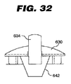
図29〜32は、カバー630を取付け具632と着脱可能に係合させるために、カバー630に関連する別法のロック構造を例示する。図29に示された断面図では、カバー630の第1の側の蝶番ロックタブ634と、カバー630の第2の側の突出部636とによって、取付け具632の内部でロックされたカバー630が例示されている。カバー630を取付け具632から取り外すためには、カバー630から外向きに延びるロックタブ634の一部が押下されて、取付け具632の内表面上に形成された溝から突出部638を解放する。次いで、カバー630は上向きに枢動されて、取付け具632中の対応する溝から突出部636を切り離し、カバーを取り外しうる。開示されたロック構造は、有利なことに、ここに開示された装置の他の実施形態に関して上で説明されたような、カバーを定位置に固定するための平紐の必要性を排除する。さらには、ロックタブ634の構成は、使用者の片手によってカバーを容易に取り外すための構造を設ける。別法として、カバーには、2つのロックタブを有するロック構造が設けられてもよい。このカバーは、上で説明された実施形態と同様に、1つのロックタブを押下することによって、または両方のロックタブを同時に押下することによって取り外されうる。
FIGS. 29-32 illustrate an alternative locking structure associated with the
図28に例示されたカバー616と同様に、カバー630は、弾性筐体642によってカバー630の下表面と接触状態に保持される円錐螺旋ばね640を含む。弾性筐体642は、ばね640をカバー630下のその定置に維持し、他方では、ばね640の圧縮特性に対応する弾性力を呈示するように設計されている。筐体642は、エポキシまたは当業者に知られている他の任意の構造によってカバー630に付着されうるロックリングによって、カバー630に固定される。
Similar to the
さらには、図29〜32に例示された内部ロック構造の別法として、図33が、外部ロック構造を使用するここで開示された取付け装置の実施形態を例示する。この分解組立図に示されているように、カバー820は、それと一体形成された外部ラッチ822を含む。カバー820が、矢印Cによって示されたように、取付け具824の方向へ移動されるとき、ラッチ822の下部は、取付け具824の上部の上に形成された周方向口縁826に接触する。カバー820がこの方向へ移動し続けると、ラッチ822は、下部が口縁826を通過してその元の位置に弾性的に撥ね戻り、それによってカバー820を取付け具824の上にロックするまで、下向きに強制される。カバー820は、ラッチ822の上部をカバー820の中心に向かう方向へ圧迫し、かつ同時にカバー820を取付け具824から離して持ち上げることによって、取付け具824から取り外されうる。
Further, as an alternative to the internal locking structure illustrated in FIGS. 29-32, FIG. 33 illustrates an embodiment of the mounting device disclosed herein that uses an external locking structure. As shown in this exploded view, the
図34は、図29〜32を参照して上で説明されたものと同様のロック構造を有するカバー650の斜視図を例示する。カバー650は、カバー650がこのカバーを取付け具の内部にロックするために、2つのロックタブ654を有する点でカバー630とは異なる。突出部658が、取付け具の内表面上の溝に係合させるために、ロックタブ654上に同様に形成される。図34には、処置ヘッド660を有する超音波処置モジュールも示されている。さらには、円錐螺旋ばね662が、処置ヘッド660を処置部位に向かう方向へ偏倚するためにカバー650の下表面に連結される。
FIG. 34 illustrates a perspective view of a cover 650 having a locking structure similar to that described above with reference to FIGS. Cover 650 differs from
図35は、超音波変換器処置ヘッドを挿入可能に受け入れるために、処置部位上にギプスを装着する前に、その部位に隣接して取付け具を装着するための装置670を例示する。装置670は、径方向突縁674をその外周囲上に有する取付け具672と、取付け具672を患者の皮膚から所定の距離だけ離して維持するためのスペーサ676と、所期の処置部位の周囲を包む芯部分678とを備える。
FIG. 35 illustrates an
ここで図37〜39を参照して、装置670のギプス装着前が説明される。最初に図37を参照すると、ギプスが装着される患者の体の一部を被って、ストッキング680が典型的に配置される。次いで、超音波処置を受けるための厳密な位置で、穴682がストッキング680の中に切り取られる。次いで、取付け具672が穴682に隣接するように、装置670が、ストッキング680の上方に位置決めされる。ここで図38に注目すると、次に芯678が所期の処置部位の周囲に覆われ、装置670が、1片のギプステープ684によって定位置に固定される。図36に例示されたように、予め中に穴を切り取ったギプステープ684が供給されることが好ましく、それは、無菌状態を維持するために封止された包装686の中に収納される。有利なことに、ギプステープ684の樹脂または接着剤は、少なくとも一部が、取付け具672のメッシュタブを含浸し、それによってギプス688に対する装置670の取付けを向上させる。ギプステープ684は、有利なことに構造的強さを装置670に与え、ギプス本体の巻付けを簡素化する。ここで図39を参照すると、ギプス本体688の内部に固定され、上で説明されたように、カバー690または超音波変換器ヘッドモジュールの準備が整った装置670が示されている。
Here, with reference to FIGS. 37 to 39, the
ここで図40〜42に注目すると、既に処置部位の周囲に装着済みのギプスの中に超音波処置ヘッドモジュールを受け入れるための装置を装着するためのシステムが例示されている。図40に示されたように、フェルトパッド700が、ギプス702の中に切り取られた空所704の内部に配置されように提供される。中心に位置する円形穴705を有するフェルトパッド700は、ギプス702の厚さに対応して寸法決めされる。有利なことに、フェルトパッド700は、空所704をギプス702の中に切り取るためのテンプレートとして最初に使用されうる。次いで、フェルトパッド700が空所704の内部に装着される。図41を参照すると、患者の処置部位に隣接して、空所704の内部にフェルトパッド700が示されており、装置706は、取付け具708がフェルトパッド700中の穴705の内部に嵌るように位置決めされる。次いで、芯710がギプス702の周囲に覆われる。ここで図42に注目すると、次いで装置706は、取付け具708の上方にぴったり付着するように構成および寸法決めされている、予め切断された1片のギプステープ712で定位置に固定される。次いで装置706およびテープ712は、約25ミリメートル幅のギプステープ714の細片によってさらに定位置に固定されうる。有利なことに、ギプステープ712の樹脂または接着剤の少なくとも一部が、取付け具708のメッシュタブを含浸し、それによってギプス702に対する取付け具708の取付けを向上させる。次いで、カバー716または超音波変換器が取付け具708の中に配置されうる。
Turning now to FIGS. 40-42, a system for mounting a device for receiving an ultrasonic treatment head module in a cast already mounted around a treatment site is illustrated. As shown in FIG. 40, a
本発明は、治療装置を整形外科用ギプスに取り付ける方法も含む。本方法は、本体および本体から延びるメッシュ突出部を備える支持体取付け具を提供する段階と、整形外科用ギプスの上に目印を付ける段階と、目印に対して開口部を整形外科用ギプスの中に開ける段階と、支持体取付け具を開口部の上方に配置する段階と、ギプス材料を支持体取付け具の上方に配置する段階とを含み、このギプスは、ギプス材料部分の少なくとも一部が支持体取付け具のメッシュ突出部を含浸するようになっている。随意選択的に、支持体取付け具は、メッシュ基部に施された接着剤被覆をさらに備え、この接着剤被覆は、ギプス材料部分の少なくとも一部がメッシュ基部を含浸するまで、メッシュ基部をギプスに一時的に付着するために使用される。本方法は、骨折の位置を特定する段階と、位置特定リングおよび平紐をギプスの上に配置する段階とをさらに含む。別法として、本方法は、周辺標識を有する支持体取付け具をギプスの上に配置する段階を含みうる。本方法はまた、医療用視覚化システムを係合する段階も含みうる。本方法は、テンプレートを使用して、目印に対して開口部を印付けする段階をさらに含みうる。別法として、本方法は、支持体取付け具を使用して、目印に対して開口部を印付けする段階をさらに含みうる。テンプレートを使用して、目印に対して開口部を印付けする段階は、テンプレートの周辺溝穴の輪郭を描く段階を含みうる。別法として、支持体取付け具を使用して、目印に対して開口部を印付けする段階は、接着テープを支持体取付け具およびギプスの上方に配置する段階を含みうる。 The present invention also includes a method of attaching a treatment device to an orthopedic cast. The method includes providing a support fixture having a body and a mesh protrusion extending from the body, marking the orthopedic cast, and opening the opening relative to the mark in the orthopedic cast. Opening the support fixture, positioning the support fixture above the opening, and positioning the cast material above the support fixture, the cast being supported by at least a portion of the cast material portion. It is designed to impregnate the mesh protrusion of the body fixture. Optionally, the support fixture further comprises an adhesive coating applied to the mesh base, wherein the adhesive coating casts the mesh base until at least a portion of the cast material portion impregnates the mesh base. Used for temporary adhesion. The method further includes locating the fracture and positioning a locating ring and a flat string over the cast. Alternatively, the method can include placing a support fixture having a perimeter marker on the cast. The method may also include engaging a medical visualization system. The method may further include marking the opening against the landmark using the template. Alternatively, the method may further include marking the opening against the landmark using a support fixture. Using the template to mark the opening relative to the landmark may include delineating the peripheral slots of the template. Alternatively, using the support fixture to mark the opening relative to the landmark may include positioning the adhesive tape over the support fixture and the cast.
幾つかの実施形態では、本発明が、患者の動きやすさを維持しながら損傷を超音波処置するためのキットを含みうる。このキットは、内部損傷の体外部位に隣接して患者によって着用されるように構成および適合され、メッシュ基部およびメッシュ基部から延びる本体を有する支持体取付け具と、超音波信号発生器を含むことができ、支持体取付け具の本体と着脱可能に係合された超音波変換器処置ヘッドモジュールと、処置ヘッドモジュールに作用的に接続された携帯可能な自蔵式主要動作ユニットとを含む。支持体取付け具の本体は、超音波変換器処置ヘッドモジュールの一部を受け入れるように構成された開口を含みうる。さらには、本体は、この開口の中へ延びる1つまたは複数の差込みラグを含むことができ、これらのラグは、その間に導電経路を形成するように電気接続される。超音波変換器処置ヘッドモジュールは、この変換器処置ヘッドモジュールの外表面から延びて、少なくとも2つの差込みラグに係合するように構成された少なくとも一部を有する1つまたは複数の溝穴付きラグを含むことが可能であり、これらの少なくとも2つの溝穴付きラグは、これらの溝穴付きラグが差込みラグに係合するときに、導電経路がこれらの溝穴付きラグの間に形成されるように、導電性プラスチックから製造される。超音波信号発生器は、信号発生器回路と、この信号発生器回路に接続された内部電源と、処置シーケンスデータを表示するために信号発生器回路に結合された表示器と、使用者によるデータ制御および/または入力を可能にするために信号発生器回路に結合されたキーパッドとを含むことが可能であり、この信号発生器回路は、プロセッサと、パルスRF信号発生器と、パルス化されたRF信号を調整するためにプロセッサに結合されたスイッチとを含む。キットの幾つかの実施形態は、超音波信号発生器と外部コンピュータとの間に通信リンクを設けるために、通信ポートとプロセッサとの間に接続された通信インターフェースを含みうる。さらには、幾つかの実施形態は、モジュールが処置に使用されていないときに超音波変換器処置ヘッドモジュールを取り代えるために、支持体取付け具と係合可能なキャップを含みうる。このキャップは、所定の圧力を皮膚表面に加えるために、キャップと患者の皮膚表面との間に位置決めされるように構成および適合されたパッドを含みうる。 In some embodiments, the present invention may include a kit for ultrasonically treating an injury while maintaining patient mobility. The kit is configured and adapted to be worn by a patient adjacent to an external body site of internal injury and includes a support fixture having a mesh base and a body extending from the mesh base, and an ultrasound signal generator. And an ultrasonic transducer treatment head module removably engaged with the body of the support fixture, and a portable self-contained main operating unit operatively connected to the treatment head module. The body of the support fixture may include an opening configured to receive a portion of the ultrasonic transducer treatment head module. Furthermore, the body can include one or more plug lugs extending into the opening, the lugs being electrically connected to form a conductive path therebetween. One or more slotted lugs having at least a portion extending from an outer surface of the transducer treatment head module and configured to engage at least two plug lugs These at least two slotted lugs are formed between the slotted lugs when the slotted lugs engage the bayonet lugs. As such, it is manufactured from conductive plastic. The ultrasonic signal generator includes a signal generator circuit, an internal power source connected to the signal generator circuit, a display coupled to the signal generator circuit for displaying treatment sequence data, and data by a user. A keypad coupled to the signal generator circuit to allow control and / or input, the signal generator circuit being pulsed with a processor, a pulsed RF signal generator, and And a switch coupled to the processor to condition the RF signal. Some embodiments of the kit may include a communication interface connected between the communication port and the processor to provide a communication link between the ultrasound signal generator and the external computer. Furthermore, some embodiments may include a cap engageable with the support fixture to replace the ultrasonic transducer treatment head module when the module is not in use for treatment. The cap may include a pad configured and adapted to be positioned between the cap and the patient's skin surface to apply a predetermined pressure to the skin surface.
以上を考慮すると、本発明の幾つかの利点が実現されかつ達成されることが分かる。 In view of the foregoing, it can be seen that the several advantages of the invention are realized and attained.
本実施形態は、本発明の原理およびその実際的な応用を最も適切に説明し、それによって当業者が、企図された特定の用途に適する様々な実施形態でかつ様々な変更を加えて、本発明の最も適切な活用を可能にするために選択されかつ記述された。 This embodiment best describes the principles of the present invention and its practical application, so that those skilled in the art will be able to make various changes and modifications to the specific embodiment intended for the particular application contemplated. Selected and described to enable the most appropriate utilization of the invention.
本発明の範囲から逸脱することなく、本明細書で説明されかつ例示された構造および方法に様々な変更が実施されうるので、以上の説明に包含されたかまたは添付の図面に示された事柄のすべては、限定ではなく例示として解釈されることが意図されている。例えば、多くの例示が、メッシュ基部を長方形の形状を有するものとして図示するが、メッシュ基部は任意の数の形状を有しうることを当業者は理解しよう。したがって、本発明の間口および範囲は、上述の典型的な実施形態のいずれかによって限定されるべきではなく、本明細書に添付された以下の特許請求の範囲およびそれらの均等物のみに従って画定されるべきである。 Various modifications may be made to the structures and methods described and illustrated herein without departing from the scope of the present invention, so that what is included in the foregoing description or illustrated in the accompanying drawings All are intended to be interpreted as illustrative rather than limiting. For example, although many examples depict the mesh base as having a rectangular shape, those skilled in the art will appreciate that the mesh base may have any number of shapes. Accordingly, the frontage and scope of the present invention should not be limited by any of the above-described exemplary embodiments, but is defined only in accordance with the following claims appended hereto and their equivalents. Should be.
10 超音波処置装置
10’ 別法の超音波処置装置
12 主要動作ユニット(MOU)
14 超音波変換器処置ヘッドモジュール
16 第1のケーブル
20 筐体
22 プリント回路基板
24 表示器組立体
26 第2のケーブル
28 取付け盤
30 表示器
31 キーパッド
32 電池保持体
34 通信ポート
35 通信インターフェース
36 筐体中のチャンネル
38 信号発生器回路
43 メモリ
44 プロセッサ
60 スイッチ
62 警報
66 受信器
67 変換器ドライバ
68 変換器
69 内部電池
70 信号監視回路
71 信号ドライバ
72 デジタル出力信号
73 取付け具連動装置
76 論理電圧コンバータ
77 電源
78 電池電圧感知回路
79 駆動信号電圧コンバータ
80 駆動信号電圧調節器
81 実時間時計
82 EEPROM
83 ゲル感知回路
84 変換器駆動回路
85 超音波変換器
86 第1のユーザインターフェース
87 第2のユーザインターフェース
88 マイクロプロセッサ
100 超音波変換器組立体
110 支持体取付け具
112 メッシュ突出部(基部)
114 本体
116 キャップ
118 ばね
120 変換器
121 ゲルまたはゲル袋
122 システムコントローラ
124 信号発生器
126 本体の内部分
128 本体の外部分
130 本体の内壁
132 本体の外壁
134 本体の開口
135 本体の近端部
136 本体の遠端部
140 本体の口縁
170 周辺標識
172 中心標識
280 位置特定リング
282 平紐
284、286 平紐の2つの部分
288 ギプス
290 目印
292 標識付けテンプレート
294 ギプス中の開口部
296 フェルトパッド
298 円筒形フェルトパッド
306 差込みラグ
308 キャップ
310 円筒形部分
312 キャップの溝穴付きラグ
314 変換器処置ヘッドモジュール突出部
316 モジュール突出部の溝穴付きラグ
318 モジュールの作用表面
400 テンプレート
402 溝穴
404 中心切抜き部
424 印付け用具
520 支持体取付け具
522 ギプスの空所
524 ギプス
526 メッシュタブ
528 超音波伝搬増強媒質
530 スペーサ
532 ギプス材料細片
534 患者の身体部分
536 取付け具の上端中の半球形切欠き
538 取付け具の凹面下端
540 取付け具の周方向溝
542 リード線
544 超音波変換器ヘッドモジュール
546 筐体
548 偏倚要素
550 コード
552 メッシュタブの一体蝶番
590 支持体取付け具
592 ギプス
594 取付け具のリード線
596 超音波変換器ヘッドモジュール
598 取付け具のカバー
600 取付け具の平紐
610 支持体取付け具
612 取付け具の円周方向リッジ
614 カバーのラッチ
616 カバー
618 カバーの円錐螺旋ばね
620 カバーの弾性筐体
622 ロックリング
624 突縁
630 カバー
632 支持体取付け具
634 カバーの第1の側の蝶番ロックタブ
636 カバーの第2の側の突出部
638 カバーのロックタブ
640 カバーのばね
642 カバーの弾性筐体
650 カバー
654 カバーのロックタブ
658 ロックタブ上の突出部
660 超音波処置ヘッド
662 カバーの円錐螺旋ばね
670 取付け具を装着するための装置
672 支持体取付け具
674 径方向突縁
676 スペーサ
678 処置部位周囲を包む芯部分
680 ストッキング
682 ストッキングの穴
684 ギプステープ
686 封止された包装
690 カバー
700 フェルトパッド
702 ギプス
704 ギプスの空所
705 フェルトパッドの円形穴
706 取付け具を装着する装置
708 支持体取付け具
710 芯
712 ギプステープ
714 ギプステープ
716 カバー
820 カバー
822 カバーの外部ラッチ
824 支持体取付け具
826 取付け具の周方向口縁
A 基部の厚さ
B 媒質
C 取付け具の方向
D1 基部の第1の寸法
D2 基部の第2の寸法
10 Ultrasonic Treatment Device 10 'Alternative
14 Ultrasonic transducer
83
114 Main body 116 Cap 118 Spring 120 Transformer 121 Gel or gel bag 122 System controller 124 Signal generator 126 Main body inner part 128 Main body outer part 130 Main body inner wall 132 Main body outer wall 134 Main body opening 135 Main body near end 136 Far end of the body 140 Mouth of the body 170 Peripheral marker 172 Center marker 280 Positioning ring 282 Flat string 284, 286 Two parts of the flat string 288 Gypsum 290 Marking 292 Labeling template 294 Opening in the cast 296 Felt pad 298 Cylindrical Felt pad 306 Insert lug 308 Cap 310 Cylindrical portion 312 Cap slot lug 314 Transducer treatment head module protrusion 316 Module protrusion slot lug 318 Module action table 400 template 402 slot 404 central cutout 424 marking tool 520 support fixture 522 cast cavity 524 cast 526 mesh tab 528 ultrasound propagation enhancing medium 530 spacer 532 cast material strip 534 patient body part 536 of fixture Hemispherical notch in upper end 538 Concave lower end of fixture 540 Circumferential groove in fixture 542 Lead wire 544 Ultrasonic transducer head module 546 Housing 548 Displacement element 550 Code 552 Integrated hinge of mesh tab 590 Support fixture 592 Cast 594 fixture lead 596 ultrasonic transducer head module 598 fixture cover 600 fixture flat string 610 support fixture 612 fixture circumferential ridge 614 cover latch 616 cover 618 Cover conical spiral spring 620 Cover elastic housing 622 Lock ring 624 Projection edge 630 Cover 632 Support fixture 634 Cover first side hinge lock tab 636 Cover second side protrusion 638 Cover lock tab 640 Cover Spring 642 Cover elastic housing 650 Cover 654 Cover lock tab 658 Protrusion on lock tab 660 Ultrasonic treatment head 662 Conical spiral spring of cover 670 Device for mounting fixture 672 Support fixture 674 Radial ridge 676 Spacer 678 Core part surrounding treatment area 680 Stocking 682 Stocking hole 684 Gypsum tape 686 Sealed packaging 690 Cover 700 Felt pad 702 Gypsum 704 Casting space 705 Felt pad circular hole 06 Device for mounting fixture 708 Support fixture 710 Core 712 Gypsum tape 714 Gypsum tape 716 Cover 820 Cover 822 Cover external latch 824 Support fixture 826 Attached peripheral edge A Base thickness B Medium C Mounting direction D1 First dimension of the base D2 Second dimension of the base
Claims (5)
a. 携帯可能な自蔵式主要動作ユニットと、
b. 前記主要動作ユニットから遠隔の内部損傷に対応する体外部位に隣接して、前記整形外科用ギプスに装着するように構成および適合されて、本体と前記本体から延びる少なくとも1つのメッシュ突出部とを有する支持体取付け具と、
c. 前記主要動作ユニットに作用的に接続され、かつ前記支持体取付け具の前記本体と着脱可能に係合された超音波変換器処置ヘッドモジュールと、
d. 前記支持体取付け具を前記整形外科用ギプスに装着するギプステープと、を備え、前記ギプステープの少なくとも一部が、前記少なくとも1つのメッシュ突出部を含浸する装置。 A device for ultrasonically treating damage in combination with an orthopedic cast;
a. A portable self-contained main motion unit,
b. Constructed and adapted to be attached to the orthopedic cast adjacent to an external location corresponding to an internal injury remote from the main motion unit, and having a body and at least one mesh projection extending from the body A support fixture;
c. An ultrasonic transducer treatment head module operatively connected to the main operating unit and removably engaged with the body of the support fixture;
d. A cast tape for mounting the support fixture to the orthopedic cast, wherein at least a portion of the cast tape impregnates the at least one mesh protrusion.
Applications Claiming Priority (3)
| Application Number | Priority Date | Filing Date | Title |
|---|---|---|---|
| US73424505P | 2005-11-07 | 2005-11-07 | |
| US60/734,245 | 2005-11-07 | ||
| PCT/US2006/060628 WO2007056734A1 (en) | 2005-11-07 | 2006-11-07 | Apparatus for mounting an ultrasonic therapeutic device to an orthopaedic cast |
Related Child Applications (1)
| Application Number | Title | Priority Date | Filing Date |
|---|---|---|---|
| JP2012207951A Division JP2012250074A (en) | 2005-11-07 | 2012-09-21 | Apparatus for mounting ultrasonic therapeutic device to orthopaedic cast |
Publications (2)
| Publication Number | Publication Date |
|---|---|
| JP2009514616A JP2009514616A (en) | 2009-04-09 |
| JP5302000B2 true JP5302000B2 (en) | 2013-09-25 |
Family
ID=37882309
Family Applications (2)
| Application Number | Title | Priority Date | Filing Date |
|---|---|---|---|
| JP2008539169A Expired - Fee Related JP5302000B2 (en) | 2005-11-07 | 2006-11-07 | Device for attaching an ultrasonic therapy device to an orthopedic cast |
| JP2012207951A Pending JP2012250074A (en) | 2005-11-07 | 2012-09-21 | Apparatus for mounting ultrasonic therapeutic device to orthopaedic cast |
Family Applications After (1)
| Application Number | Title | Priority Date | Filing Date |
|---|---|---|---|
| JP2012207951A Pending JP2012250074A (en) | 2005-11-07 | 2012-09-21 | Apparatus for mounting ultrasonic therapeutic device to orthopaedic cast |
Country Status (9)
| Country | Link |
|---|---|
| US (2) | US20100152624A1 (en) |
| EP (1) | EP1948315B1 (en) |
| JP (2) | JP5302000B2 (en) |
| AT (1) | ATE439165T1 (en) |
| AU (1) | AU2006311299B2 (en) |
| CA (1) | CA2628824A1 (en) |
| DE (1) | DE602006008492D1 (en) |
| ES (1) | ES2329722T3 (en) |
| WO (1) | WO2007056734A1 (en) |
Cited By (1)
| Publication number | Priority date | Publication date | Assignee | Title |
|---|---|---|---|---|
| JP2012250074A (en) * | 2005-11-07 | 2012-12-20 | Smith & Nephew Inc | Apparatus for mounting ultrasonic therapeutic device to orthopaedic cast |
Families Citing this family (26)
| Publication number | Priority date | Publication date | Assignee | Title |
|---|---|---|---|---|
| US10219815B2 (en) | 2005-09-22 | 2019-03-05 | The Regents Of The University Of Michigan | Histotripsy for thrombolysis |
| US20100204618A1 (en) * | 2007-07-30 | 2010-08-12 | Regenprime Co., Ltd. | Ultrasound equipment for treating of edema and use thereof |
| GB0803272D0 (en) * | 2008-02-22 | 2008-04-02 | Smith & Nephew | Ultrasound and tissue repair |
| US9901753B2 (en) | 2009-08-26 | 2018-02-27 | The Regents Of The University Of Michigan | Ultrasound lithotripsy and histotripsy for using controlled bubble cloud cavitation in fractionating urinary stones |
| AU2010289769B2 (en) | 2009-08-26 | 2016-06-30 | Histosonics, Inc. | Micromanipulator control arm for therapeutic and imaging ultrasound transducers |
| TWI483710B (en) * | 2010-05-17 | 2015-05-11 | Hon Hai Prec Ind Co Ltd | Device capable of testing bone density and system thereof |
| JP5566195B2 (en) * | 2010-06-11 | 2014-08-06 | 伊藤超短波株式会社 | Ultrasonic therapy device and ultrasonic therapy system |
| EP2584972A2 (en) * | 2010-06-24 | 2013-05-01 | Zetroz LLC | Hydrogel ultrasound coupling device |
| CA2814657A1 (en) | 2010-10-12 | 2012-04-19 | Kevin J. Tanis | Medical device |
| AU2011354720A1 (en) * | 2011-01-14 | 2013-05-30 | Debra Ann Arrington | Medical device with temperature sensor |
| KR101224480B1 (en) | 2011-01-31 | 2013-01-21 | 전북대학교산학협력단 | Vibratory stimulation device for gips |
| US9144694B2 (en) | 2011-08-10 | 2015-09-29 | The Regents Of The University Of Michigan | Lesion generation through bone using histotripsy therapy without aberration correction |
| US10342649B2 (en) * | 2011-09-15 | 2019-07-09 | Sigma Instruments Holdings, Llc | System and method for treating animals |
| WO2013166019A1 (en) * | 2012-04-30 | 2013-11-07 | The Regents Of The University Of Michigan | Ultrasound transducer manufacturing using rapid-prototyping method |
| US20140100459A1 (en) | 2012-10-05 | 2014-04-10 | The Regents Of The University Of Michigan | Bubble-induced color doppler feedback during histotripsy |
| US11432900B2 (en) | 2013-07-03 | 2022-09-06 | Histosonics, Inc. | Articulating arm limiter for cavitational ultrasound therapy system |
| US10293187B2 (en) | 2013-07-03 | 2019-05-21 | Histosonics, Inc. | Histotripsy excitation sequences optimized for bubble cloud formation using shock scattering |
| WO2015027164A1 (en) | 2013-08-22 | 2015-02-26 | The Regents Of The University Of Michigan | Histotripsy using very short ultrasound pulses |
| CN104739443B (en) * | 2013-12-30 | 2018-06-26 | 深圳迈瑞生物医疗电子股份有限公司 | A kind of medical external supersonic probe and diasonograph |
| EP3215013A2 (en) | 2014-11-04 | 2017-09-13 | Osteoid Saglik Teknolojileri A.S. | Methods for integrating sensors and effectors in custom three-dimensional orthosis |
| CN108348772B (en) | 2015-06-24 | 2020-03-03 | 美国密歇根州立大学试剂中心 | Histotripsy therapy system and method for treating brain tissue |
| AU2018283147B2 (en) * | 2017-06-15 | 2023-07-13 | Avent, Inc. | Device to reduce steam pops and increase tissue stability during radiofrequency ablation |
| US11020188B2 (en) | 2017-11-10 | 2021-06-01 | Sigma Instruments Holdings, Llc | System, method, and GUI for treating skin and underlying tissues for improved health, function and/or appearance |
| US11813484B2 (en) | 2018-11-28 | 2023-11-14 | Histosonics, Inc. | Histotripsy systems and methods |
| EP3738502A1 (en) | 2019-05-14 | 2020-11-18 | Koninklijke Philips N.V. | An assembly for mounting a sensor on skin |
| AU2021213168A1 (en) | 2020-01-28 | 2022-09-01 | The Regents Of The University Of Michigan | Systems and methods for histotripsy immunosensitization |
Family Cites Families (17)
| Publication number | Priority date | Publication date | Assignee | Title |
|---|---|---|---|---|
| US2855922A (en) * | 1954-06-03 | 1958-10-14 | Gerald W Schroeder | Windows for surgical casts |
| US3116731A (en) * | 1962-04-30 | 1964-01-07 | Thomas E Baxter | Cast ventilating arrangement |
| US3482609A (en) * | 1967-06-27 | 1969-12-09 | Kendall & Co | Covering for seed bed or plant |
| US4491128A (en) * | 1982-08-19 | 1985-01-01 | Haschke Paul C | Method of making a surgical cast with window |
| US4506676A (en) * | 1982-09-10 | 1985-03-26 | Duska Alois A | Radiographic localization technique |
| US4535779A (en) * | 1983-03-04 | 1985-08-20 | Empi, Inc. | Transcutaneous electrode device for cast-covered sites |
| US4583550A (en) * | 1984-05-07 | 1986-04-22 | Biolectron, Inc. | Access window assembly for a body cast |
| US4574809A (en) * | 1984-06-29 | 1986-03-11 | Electro-Biology, Inc. | Portable non-invasive electromagnetic therapy equipment |
| US4677970A (en) * | 1985-08-09 | 1987-07-07 | Green Carlos J | Orthopedic heat transfer system for orthopedic casts |
| US5186162A (en) * | 1988-09-14 | 1993-02-16 | Interpore Orthopaedics, Inc. | Ultrasonic transducer device for treatment of living tissue and/or cells |
| US5618263A (en) * | 1992-08-18 | 1997-04-08 | Maurice Adam | Soft splint |
| US5374283A (en) * | 1993-12-01 | 1994-12-20 | Flick; A. Bart | Electrical therapeutic apparatus |
| US5556372A (en) * | 1995-02-15 | 1996-09-17 | Exogen, Inc. | Apparatus for ultrasonic bone treatment |
| US6165144A (en) * | 1998-03-17 | 2000-12-26 | Exogen, Inc. | Apparatus and method for mounting an ultrasound transducer |
| US6607500B2 (en) * | 1999-07-08 | 2003-08-19 | Cyclotec Advanced Medical Technologies, Inc. | Integrated cast and muscle stimulation system |
| US6436030B2 (en) * | 2000-01-31 | 2002-08-20 | Om P. Rehil | Hiatal hernia repair patch and method for using the same |
| DE602006008492D1 (en) * | 2005-11-07 | 2009-09-24 | Smith & Nephew Inc | DEVICE FOR MOUNTING AN ULTRASONIC THERAPY DEVICE TO AN ORTHOPEDIC GIPS |
-
2006
- 2006-11-07 DE DE602006008492T patent/DE602006008492D1/en active Active
- 2006-11-07 JP JP2008539169A patent/JP5302000B2/en not_active Expired - Fee Related
- 2006-11-07 AU AU2006311299A patent/AU2006311299B2/en not_active Ceased
- 2006-11-07 WO PCT/US2006/060628 patent/WO2007056734A1/en active Application Filing
- 2006-11-07 AT AT06839751T patent/ATE439165T1/en not_active IP Right Cessation
- 2006-11-07 EP EP06839751A patent/EP1948315B1/en not_active Not-in-force
- 2006-11-07 ES ES06839751T patent/ES2329722T3/en active Active
- 2006-11-07 CA CA002628824A patent/CA2628824A1/en not_active Abandoned
- 2006-11-07 US US12/092,849 patent/US20100152624A1/en not_active Abandoned
-
2012
- 2012-04-16 US US13/447,561 patent/US20120197165A1/en not_active Abandoned
- 2012-09-21 JP JP2012207951A patent/JP2012250074A/en active Pending
Cited By (1)
| Publication number | Priority date | Publication date | Assignee | Title |
|---|---|---|---|---|
| JP2012250074A (en) * | 2005-11-07 | 2012-12-20 | Smith & Nephew Inc | Apparatus for mounting ultrasonic therapeutic device to orthopaedic cast |
Also Published As
| Publication number | Publication date |
|---|---|
| CA2628824A1 (en) | 2007-05-18 |
| AU2006311299B2 (en) | 2012-02-02 |
| WO2007056734A1 (en) | 2007-05-18 |
| EP1948315A1 (en) | 2008-07-30 |
| EP1948315B1 (en) | 2009-08-12 |
| ES2329722T3 (en) | 2009-11-30 |
| JP2009514616A (en) | 2009-04-09 |
| DE602006008492D1 (en) | 2009-09-24 |
| ATE439165T1 (en) | 2009-08-15 |
| JP2012250074A (en) | 2012-12-20 |
| US20100152624A1 (en) | 2010-06-17 |
| AU2006311299A1 (en) | 2007-05-18 |
| US20120197165A1 (en) | 2012-08-02 |
Similar Documents
| Publication | Publication Date | Title |
|---|---|---|
| JP5302000B2 (en) | Device for attaching an ultrasonic therapy device to an orthopedic cast | |
| FI112035B (en) | Device for bone ultrasound | |
| EP1064052B1 (en) | Apparatus and method for mounting an ultrasound transducer | |
| EP3288615B1 (en) | Controlling usage of replaceable tool ends | |
| EP2753393B1 (en) | System for pain reduction during skin puncture and breakable tip therefor | |
| AU718497B2 (en) | Locator method and apparatus | |
| US20040064051A1 (en) | Ultrasound transducer coupling apparatus | |
| NO315547B1 (en) | Medical patch | |
| CA2212230C (en) | Apparatus for ultrasonic bone treatment | |
| MXPA97006154A (en) | Apparatus for ultrasonic treatment of the hu |
Legal Events
| Date | Code | Title | Description |
|---|---|---|---|
| A621 | Written request for application examination |
Free format text: JAPANESE INTERMEDIATE CODE: A621 Effective date: 20090522 |
|
| A131 | Notification of reasons for refusal |
Free format text: JAPANESE INTERMEDIATE CODE: A131 Effective date: 20111025 |
|
| A977 | Report on retrieval |
Free format text: JAPANESE INTERMEDIATE CODE: A971007 Effective date: 20111027 |
|
| A02 | Decision of refusal |
Free format text: JAPANESE INTERMEDIATE CODE: A02 Effective date: 20120522 |
|
| A521 | Request for written amendment filed |
Free format text: JAPANESE INTERMEDIATE CODE: A523 Effective date: 20120921 |
|
| A911 | Transfer to examiner for re-examination before appeal (zenchi) |
Free format text: JAPANESE INTERMEDIATE CODE: A911 Effective date: 20120928 |
|
| A912 | Re-examination (zenchi) completed and case transferred to appeal board |
Free format text: JAPANESE INTERMEDIATE CODE: A912 Effective date: 20121122 |
|
| A521 | Request for written amendment filed |
Free format text: JAPANESE INTERMEDIATE CODE: A523 Effective date: 20130419 |
|
| A61 | First payment of annual fees (during grant procedure) |
Free format text: JAPANESE INTERMEDIATE CODE: A61 Effective date: 20130620 |
|
| R150 | Certificate of patent or registration of utility model |
Free format text: JAPANESE INTERMEDIATE CODE: R150 |
|
| LAPS | Cancellation because of no payment of annual fees |