JP5299552B2 - Vehicle power hop detection method - Google Patents
Vehicle power hop detection method Download PDFInfo
- Publication number
- JP5299552B2 JP5299552B2 JP2012235255A JP2012235255A JP5299552B2 JP 5299552 B2 JP5299552 B2 JP 5299552B2 JP 2012235255 A JP2012235255 A JP 2012235255A JP 2012235255 A JP2012235255 A JP 2012235255A JP 5299552 B2 JP5299552 B2 JP 5299552B2
- Authority
- JP
- Japan
- Prior art keywords
- amplitude
- power hop
- power
- vehicle
- period
- Prior art date
- Legal status (The legal status is an assumption and is not a legal conclusion. Google has not performed a legal analysis and makes no representation as to the accuracy of the status listed.)
- Expired - Fee Related
Links
Images


Classifications
-
- B—PERFORMING OPERATIONS; TRANSPORTING
- B60—VEHICLES IN GENERAL
- B60W—CONJOINT CONTROL OF VEHICLE SUB-UNITS OF DIFFERENT TYPE OR DIFFERENT FUNCTION; CONTROL SYSTEMS SPECIALLY ADAPTED FOR HYBRID VEHICLES; ROAD VEHICLE DRIVE CONTROL SYSTEMS FOR PURPOSES NOT RELATED TO THE CONTROL OF A PARTICULAR SUB-UNIT
- B60W30/00—Purposes of road vehicle drive control systems not related to the control of a particular sub-unit, e.g. of systems using conjoint control of vehicle sub-units
- B60W30/18—Propelling the vehicle
- B60W30/20—Reducing vibrations in the driveline
Landscapes
- Engineering & Computer Science (AREA)
- Automation & Control Theory (AREA)
- Transportation (AREA)
- Mechanical Engineering (AREA)
- Control Of Driving Devices And Active Controlling Of Vehicle (AREA)
- Control Of Vehicle Engines Or Engines For Specific Uses (AREA)
- Electrical Control Of Air Or Fuel Supplied To Internal-Combustion Engine (AREA)
- Combined Controls Of Internal Combustion Engines (AREA)
- Electric Propulsion And Braking For Vehicles (AREA)
- Auxiliary Drives, Propulsion Controls, And Safety Devices (AREA)
- Regulating Braking Force (AREA)
Abstract
Description
本発明は車両のパワーホップ検出方法に関するものである。 The present invention relates to a vehicle power hop detection method .
車両は、例えばオフロード状態を含めた様々な道路や地形を走行する。例えば車両は、車輪を前方方向に動かし始めるのに十分な駆動力を発生できるが、前進を維持するのに十分な駆動力を出せない状態(例えば陥没部や岩石階段)に遭遇することがある。そのような状況では、車輪は路面を掴んだり滑ったりし、これにより車両に前後方向の振動が引き起こされる(例えば特許文献1〜6を参照)。
The vehicle travels on various roads and terrain including, for example, an off-road state. For example, a vehicle may encounter a condition (eg, a depression or a rock staircase) that can generate enough driving force to begin moving the wheels forward, but not enough driving force to keep moving forward. . In such a situation, the wheel grips or slides on the road surface, thereby causing the vehicle to vibrate in the front-rear direction (see, for example,
パワーホップが発生しやすい傾向の車両においては、例えば前後方向の振動が駆動系やサスペンションによって増幅されることがある。オフロード走行中等、継続的に前後方向の振動が発生する。状態においては、車両が損傷を受ける恐れがある。具体的には、車両の駆動伝達系に損傷が生じる恐れがある。 In a vehicle that tends to generate power hops, for example, vibration in the front-rear direction may be amplified by a drive system or suspension. Longitudinal vibrations occur continuously during off-road driving. In some situations, the vehicle may be damaged. Specifically, the vehicle drive transmission system may be damaged.
本発明は上記点に鑑みてなされたものであり、車両が損傷を受ける可能性のあるパワーホップ状態を検出し、さらにそのような場合にパワーホップ状態を緩和することを目的とする。 The present invention has been made in view of the above points, and an object of the present invention is to detect a power hop state in which the vehicle may be damaged, and to reduce the power hop state in such a case.
請求項1にかかる発明は、車両の前後加速度の現在と前回の信号を含む連続した複数の信号を取得し、前記連続した信号の周期と振幅を算出し、前記連続した信号のそれぞれの周期と振幅の組み合わせが第1所定値を上回るか判定し、前記現在の信号の周期と振幅の組み合わせが、前記第1所定値よりも大きい第2所定値を上回るか判定し、前記前回の信号の周期と振幅の組み合わせが前記第1所定値を上回り、かつ前記現在の信号の周期と振幅の組み合わせが前記第2所定値を上回るかどうかに基づいてパワーホップの状態を判断することを特徴とする。
The invention according to
請求項2にかかる発明は、前記現在の信号の振幅が前記前回の信号の振幅の所定割合を上回るか判定し、前記現在の信号の振幅が前記前回の信号の振幅の所定割合を上回るかどうかに基づいてパワーホップの状態を判断することを特徴とする。 The invention according to claim 2 determines whether the amplitude of the current signal exceeds a predetermined ratio of the amplitude of the previous signal, and whether the amplitude of the current signal exceeds a predetermined ratio of the amplitude of the previous signal. The power hop state is determined based on the above.
請求項3にかかる発明は、前記現在の信号の振幅が所定回数に渡って前記前回の信号の振幅の前記所定割合を上回るかどうかに基づいてパワーホップの状態を判断することを特徴とする構成としてある。 The invention according to claim 3 is characterized in that the state of the power hop is determined based on whether the amplitude of the current signal exceeds the predetermined ratio of the amplitude of the previous signal over a predetermined number of times. It is as.
請求項4にかかる発明は、前記現在の信号の周期と振幅の組み合わせが、少なくとも前記所定回数に渡って前記第1所定値を上回り、前記現在の信号の振幅が少なくとも前記所定回数に渡って前記前回の信号の前記所定割合を上回り、前記現在の信号の周期と振幅の組み合わせが前記第2所定値を上回る場合にパワーホップ状態であると判断することを特徴とする。 According to a fourth aspect of the present invention, the combination of the period and the amplitude of the current signal exceeds the first predetermined value at least for the predetermined number of times, and the amplitude of the current signal is at least for the predetermined number of times. The power hop state is determined when the predetermined ratio of the previous signal exceeds the predetermined ratio and the combination of the current signal period and amplitude exceeds the second predetermined value.
請求項5にかかる発明は、前記現在の信号の周期と振幅の組み合わせが前記第1所定値未満、または前記現在の信号の振幅が前記前回の信号の振幅の前記所定割合未満の場合に、パワーホップ状態ではないと判断することを特徴とする。 According to a fifth aspect of the present invention, when the combination of the period and amplitude of the current signal is less than the first predetermined value , or the amplitude of the current signal is less than the predetermined ratio of the amplitude of the previous signal, It is characterized by determining that it is not a hop state .
本発明によれば、車両のパワーホップ状態を精度良く検出し、パワーホップ状態が検出された場合にパワーホップ状態を緩和することによって車両の駆動伝達系に損傷が生じることを防止することが可能になる。 According to the present invention, it is possible to accurately detect the power hop state of a vehicle and to prevent damage to the drive transmission system of the vehicle by relaxing the power hop state when the power hop state is detected. become.
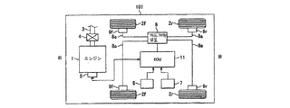
以下、本発明の実施例を添付図面に基づいて説明する。図1に示すように、車両101にはエンジン1が備えられている。エンジン1は例えば内燃機関エンジンであり、スロットルバルブ4によって制御される吸気口3を備える。エンジン1は内燃機関エンジンに限定されず、電気モータ、内燃機関エンジンと電気モータによるハイブリッドエンジンや燃料電池などでもよい。
Embodiments of the present invention will be described below with reference to the accompanying drawings. As shown in FIG. 1, the
車両101は、ブレーキ9f、9rにより制動される車輪2f、2rを備える。液圧制御装置8は液圧管8aを通じてブレーキ9f、9rの液圧を制御する。液圧制御装置8は、ブレーキペダルセンサと車両センサ6,7の両方、あるいは一方の入力に基づいてブレーキ9f、9rを制御する。
The
電子制御装置(ECU)11は車両センサ6,7からの入力を受信する。車両センサ7は前後加速度センサである。車両センサ6は、車速センサ、横加速度センサ、ヨーレートセンサなどである。またこれらに限定されず、車輪速度センサなど他のセンサを用いても良い。 The electronic control unit (ECU) 11 receives inputs from the vehicle sensors 6 and 7. The vehicle sensor 7 is a longitudinal acceleration sensor. The vehicle sensor 6 is a vehicle speed sensor, a lateral acceleration sensor, a yaw rate sensor, or the like. Moreover, it is not limited to these, You may use other sensors, such as a wheel speed sensor.
ECU11は、パワートレイン電子制御装置(パワートレインECU)5からの入力を受信し、パワートレインECU5に指令を送信する。パワートレインECU5は駆動トルクやギヤ比、ギヤ位置などの情報をECU11に送信する。そして、ECU11はエンジントルク指令などをパワートレインECU5に送信する。
The ECU 11 receives an input from the power train electronic control device (power train ECU) 5 and transmits a command to the
図2に示すように、本発明に適用可能なトラクション制御システムは、ECU11、パワートレインECU5と液圧制御装置8とから構成される。車輪速度センサ、前後加速度センサ7、横加速度センサからの入力と、二次入力(例えばヨーレートセンサ、アクセルペダル操作を検出するアクセルペダルセンサなどからの入力)がECU11に供給される。ECU11は、車両のパワーホップ状態を検出し、緩和するコンピュータプログラムを記憶した記憶装置を備える。また、ECU11は実際の駆動トルクやギヤ比、ギヤ位置などの情報をパワートレインECU5から受信可能である。さらに、ECU11は要求される駆動トルクをエンジン1に供給するための指示をパワートレインECU5に送信する。また、ECU11は、制動制御要求を液圧制御装置8に送信し、ブレーキ9f、9rを駆動する。なお、液圧制御装置8は、車輪2f、2rに与えられる制動力をそれぞれ独立して制御するように構成してもよい。
As shown in FIG. 2, the traction control system applicable to the present invention includes an
以下に述べるように、パワーホップ状態の検出やパワーホップ状態の緩和は、図2に示すトラクション制御システムを用いて実現可能であり、また前後加速度センサ7のECU11への入力とECU11からパワートレインECU5への駆動トルク要求のみで実現可能である。
As described below, the detection of the power hop state and the relaxation of the power hop state can be realized by using the traction control system shown in FIG. 2, and the input to the
図3はパワーホップ検出処理を示すフローチャートである。この処理は、車両が始動し始めたときから行ってもよい。あるいは、検出処理が、運転手や乗員によって選択的に開始されるようにしてもよい。例えば、本実施例に示すパワーホップ検出・緩和システムおよび方法は、適切なスイッチなどによって二輪駆動モードから四輪駆動モードに切換可能な車両に適用可能である。そのような車両の場合、車両が四輪駆動モードに切り換えられたときにパワーホップ検出・緩和処理が行われる。そのほかには、車両がオフロードを走行する際にスイッチを作動させて、この検出処理を実行するようにしてもよい。 FIG. 3 is a flowchart showing the power hop detection process. This process may be performed from when the vehicle starts to start. Alternatively, the detection process may be selectively started by a driver or an occupant. For example, the power hop detection / mitigation system and method shown in the present embodiment can be applied to a vehicle that can be switched from a two-wheel drive mode to a four-wheel drive mode by an appropriate switch or the like. In the case of such a vehicle, the power hop detection / mitigation process is performed when the vehicle is switched to the four-wheel drive mode. In addition, this detection process may be executed by operating a switch when the vehicle travels off-road.
パワーホップ検出処理において、まずステップS10でECU11が前後加速度センサ7から信号を受信する。そしてステップS20に進んで、前後加速度センサ信号を周知の処理に従ってフィルター処理する。次にステップS30においてフィルター処理された前後加速度センサ信号の最高値と最低値を検出し、次のステップS40においてフィルター処理された前後加速度センサ信号の周期と振幅を求める。前後加速度センサ信号の周期と振幅は、振動の半周期に基づいて算出できる。
In the power hop detection process, first, the
ステップS50において、周期と振幅の組み合わせを表す点が、図3に示すパワーホップ振動マップに記憶された第1パワーホップ値PH_Map1以上か否かを判定する。パワーホップ振動マップはECU11の記憶装置に格納してもよい。図3に示すパワーホップ振動マップの数値は一例であり、それ以外のパワーホップ値であってもよい。
In step S50, it is determined whether or not the point representing the combination of period and amplitude is greater than or equal to the first power hop value PH_Map1 stored in the power hop vibration map shown in FIG. The power hop vibration map may be stored in a storage device of the
ステップS50において、現在の前後加速度センサ信号(例えば振動の半周期)の周期と振幅の組み合わせを示す点が、第1パワーホップ値PH_Map1以上であると判定されると、ステップS60に進み、フィルター処理された前後加速度センサ信号の振幅が前回の(すぐ直前の)前後加速度センサ信号の振幅の所定割合X%よりも大きいか否かを判定する。所定の割合については、車両により異なる。例えば、所定の割合は80%に設定される。ステップS60では現在の前後加速度センサ信号と直前の前後加速度センサ信号との関係を判断するために、現在の前後加速度センサ信号の振幅と直前の前後加速度センサ信号の振幅を比較する。現在の前後加速度センサ信号の振幅が、直前の前後加速度センサ信号の振幅の所定割合を上回る場合は、車両がパワーホップ緩和処理が必要となるパワーホップ状態の兆候を示していると判断し、ステップS70に進み、パワーホップカウンタを1だけ増やす。パワーホップ検出処理は、さらにステップS80に進み、パワーホップカウンタが所定のカウンタ値N(0ではない正の整数)に等しいかどうか判定するためパワーホップカウンタを確認する。例えば、このパワーホップカウンタの所定値は4に設定される。パワーホップカウンタの所定値は車両により異なり、0以外の正の整数であればどのような値に設定されてもよい。このパワーホップカウンタは、ステップS70にて最大Nまで増加される。 If it is determined in step S50 that the point indicating the combination of the period and amplitude of the current longitudinal acceleration sensor signal (for example, a half period of vibration) is greater than or equal to the first power hop value PH_Map1, the process proceeds to step S60, and filter processing is performed. It is determined whether or not the amplitude of the obtained longitudinal acceleration sensor signal is larger than a predetermined ratio X% of the amplitude of the previous (immediately previous) longitudinal acceleration sensor signal. About a predetermined ratio, it changes with vehicles. For example, the predetermined ratio is set to 80%. In step S60, the current longitudinal acceleration sensor signal is compared with the previous longitudinal acceleration sensor signal in order to determine the relationship between the current longitudinal acceleration sensor signal and the immediately preceding longitudinal acceleration sensor signal. If the amplitude of the current longitudinal acceleration sensor signal exceeds a predetermined ratio of the amplitude of the immediately preceding longitudinal acceleration sensor signal, it is determined that the vehicle is showing an indication of a power hop condition that requires a power hop mitigation process, and step Proceeding to S70, the power hop counter is incremented by one. The power hop detection process further proceeds to step S80, where the power hop counter is checked to determine whether the power hop counter is equal to a predetermined counter value N (a positive integer that is not 0). For example, the predetermined value of this power hop counter is set to 4. The predetermined value of the power hop counter differs depending on the vehicle and may be set to any value as long as it is a positive integer other than zero. This power hop counter is increased to a maximum N in step S70.
パワーホップカウンタの値が所定のカウンタ値Nに等しくない場合(ステップS80においてNOという判定がなされた場合)、パワーホップ検出処理はステップS90に進み、パワーホップメモリフラグをOFFにする。パワーホップフラグは、現在のサイクルでパワーホップが検出されたかを示すために使用される。ステップS90以降は、パワーホップ緩和処理に移行する。パワーホップ緩和処理の詳細は図4に基づいて以下に述べる。 If the value of the power hop counter is not equal to the predetermined counter value N (if NO is determined in step S80), the power hop detection process proceeds to step S90, and the power hop memory flag is turned OFF. The power hop flag is used to indicate whether a power hop has been detected in the current cycle. After step S90, the process proceeds to power hop mitigation processing. Details of the power hop mitigation process will be described below with reference to FIG.
フィルター処理を施された一連の前後加速度センサ信号に示される周期と振幅の組み合わせが、第1パワーホップ値PH_Map1をN回上回り、かつ一連の前後加速度センサ信号のそれぞれの振幅が直前の前後加速度センサ信号のX%をN回上回る場合に、ステップS80で肯定判定される(ステップS80のYES)。つまり、ステップS80において、振動の振幅に比較的短期間の急上昇が現れるような環境下を車両が走行する状況(例えば車両が道路の隆起や溝の上を走行する場合)を判定できる。このような状況は、パワーホップの緩和処理が必要な状態ではないが、本実施例ではパワーホップの緩和処理が不必要に実行されないように、このような状態も判定できるように構成されている。 The combination of the period and amplitude indicated in the filtered series of longitudinal acceleration sensor signals exceeds the first power hop value PH_Map1 N times, and the respective longitudinal acceleration sensor signals immediately before the amplitude of the series of longitudinal acceleration sensor signals If X% of the signal is exceeded N times, an affirmative determination is made in step S80 (YES in step S80). That is, in step S80, it is possible to determine a situation in which the vehicle travels in an environment in which a relatively short-term sudden increase in the amplitude of vibration appears (for example, when the vehicle travels on a road or on a groove). Such a situation is not a state where power hop relaxation processing is required, but in this embodiment, such a state can be determined so that power hop relaxation processing is not unnecessarily executed. .
パワーホップカウンタが所定のカウンタ値Nと等しい場合、つまりステップS80で肯定判定がなされた場合(ステップS80での判定がYES)、ステップS100に進む。ステップS100において、フィルター処理された前後加速度センサ信号の周期と振幅の組み合わせによって示される点が、図3のパワーホップ振動マップから得られる第2パワーホップ値PH_Map2を上回るか否かが判定される。図示されるように第2パワーホップ値PH_Map2は第1パワーホップ値PH_Map1よりも大きく設定されている。周期と振幅の組み合わせによって表される点が第2パワーホップ値PH_Map2未満の場合(ステップS100のNO)、パワーホップ検出処理はステップS90に進み、パワーホップフラグをOFFにする。以下、図4に示されるパワーホップ緩和処理に移行する。一方で、周期と振幅の組み合わせによって表される点が第2パワーホップ値PH_Map2を上回る場合(ステップS100のYES)、ステップS110に進み、パワーホップフラグをONにする。そして図4に示すパワーホップ緩和処理に移行する。 If the power hop counter is equal to the predetermined counter value N, that is, if an affirmative determination is made in step S80 (YES in step S80), the process proceeds to step S100. In step S100, it is determined whether or not the point indicated by the combination of the period and amplitude of the filtered longitudinal acceleration sensor signal exceeds the second power hop value PH_Map2 obtained from the power hop vibration map of FIG. As illustrated, the second power hop value PH_Map2 is set larger than the first power hop value PH_Map1. When the point represented by the combination of the period and the amplitude is less than the second power hop value PH_Map2 (NO in step S100), the power hop detection process proceeds to step S90, and the power hop flag is turned OFF. Hereinafter, the process proceeds to the power hop mitigation process shown in FIG. On the other hand, when the point represented by the combination of the period and the amplitude exceeds the second power hop value PH_Map2 (YES in step S100), the process proceeds to step S110, and the power hop flag is turned ON. And it transfers to the power hop relaxation process shown in FIG.
以下に、第1パワーホップ値PH_Map1を用いて車両が緩和処理の必要なパワーホップ状態に近づきつつあることを判定するシステムおよび方法を説明する。本実施例では、いくつか(例えば、N回)の一連のフィルター処理された前後加速度センサ信号が第1パワーホップ値PH_Map1を上回る場合、車両がパワーホップ緩和処理によって制御されるべきパワーホップ状態に近づきつつあると判断される。また、いくつか(例えば、N回)の一連のフィルター処理された前後加速度センサ信号が第1パワーホップ値PH_Map1を上回ると判定し、次の前後加速度センサ信号の周期と振幅の組み合わせが第2パワーホップ値PH_Map2を上回るときには、即座にパワーホップ状態であると判断できるように構成されている。 In the following, a system and method for determining that a vehicle is approaching a power hop state that requires mitigation processing using the first power hop value PH_Map1 will be described. In this example, if a number of (eg, N) series of filtered longitudinal acceleration sensor signals exceed the first power hop value PH_Map1, the vehicle is in a power hop state to be controlled by the power hop mitigation process. Judged to be approaching. Further, it is determined that a series of filtered longitudinal acceleration sensor signals of several (for example, N times) exceeds the first power hop value PH_Map1, and the combination of the period and amplitude of the next longitudinal acceleration sensor signal is the second power. When the value exceeds the hop value PH_Map2, the power hop state can be immediately determined.
ステップS50に戻って、現在のサイクルにおけるフィルター処理された前後加速度センサ信号の周期と振幅の組み合わせが第1パワーホップ値PH_Map1未満である場合、パワーホップ検出処理はS65に進み、パワーホップカウンタを0を下限として1減少させる。同様に、現在のサイクルにおけるフィルター処理された前後加速度センサ信号の周期と振幅の組み合わせが前回の(直前の)フィルタ処理された前後加速度センサ信号、または前後加速度センサ信号の所定割合X%未満である場合(ステップS60のNO)、パワーホップ検出処理はステップS65に進み、パワーホップカウンタを1減少させる。そしてステップS65からステップS90に進み、パワーホップフラグをOFFにする。その後パワーホップ検出処理は、図4に示されるパワーホップ緩和処理に移行する。 Returning to step S50, if the combination of the period and amplitude of the filtered longitudinal acceleration sensor signal in the current cycle is less than the first power hop value PH_Map1, the power hop detection process proceeds to S65 and the power hop counter is set to 0. Is reduced by 1 as the lower limit. Similarly, the combination of the period and amplitude of the filtered longitudinal acceleration sensor signal in the current cycle is less than the previous (previous) filtered longitudinal acceleration sensor signal or a predetermined ratio X% of the longitudinal acceleration sensor signal. If so (NO in step S60), the power hop detection process proceeds to step S65, and the power hop counter is decremented by one. Then, the process proceeds from step S65 to step S90, and the power hop flag is turned OFF. Thereafter, the power hop detection process proceeds to the power hop relaxation process shown in FIG.
図4はパワーホップ緩和処理の詳細を示す。パワーホップ緩和処理はステップS200から始まり、そこでパワーホップフラグがONかどうか判定される。パワーホップフラグがONの場合、パワーホップ緩和処理はステップS210に進み、パワーホップメモリフラグがONかどうか判定する。ここで、図示された本実施例では、パワーホップ緩和処理が実行されている間(つまりパワーホップ検出処理結果に応じてエンジントルクの減少が実行されている間)、例えばECU11に格納されるパワーホップメモリフラグがONにされる。一方で、パワーホップ緩和処理が実行されていない場合には、パワーホップメモリフラグがOFFにされる。
FIG. 4 shows details of the power hop mitigation process. The power hop mitigation process starts from step S200, where it is determined whether the power hop flag is ON. If the power hop flag is ON, the power hop mitigation process proceeds to step S210, and it is determined whether the power hop memory flag is ON. Here, in the illustrated embodiment, the power stored in the
ステップS210において、パワーホップメモリフラグがONでない場合、つまりパワーホップ緩和処理が現在実行されていない場合、ステップS220に進み、パワーホップメモリフラグをONにする。そしてパワーホップ緩和処理はステップS230に進み、そこでECU11はパワーホップの度合いを軽減するために、エンジントルクを自動的に減少させるようにパワートレインECU5に指令を出す。そしてステップS10に戻る。
In step S210, if the power hop memory flag is not ON, that is, if the power hop mitigation process is not currently executed, the process proceeds to step S220, and the power hop memory flag is turned ON. Then, the power hop mitigation process proceeds to step S230, where the
ステップS210において、パワーホップメモリフラグがONであると判定されると、つまりパワーホップ緩和処理が実行中であると判断されると、ステップS240に進み、エンジントルクの減少を継続し、その後ステップS10に戻る。 If it is determined in step S210 that the power hop memory flag is ON, that is, if it is determined that the power hop mitigation process is being performed, the process proceeds to step S240, and the engine torque is continuously reduced. Return to.
ステップS200において、パワーホップフラグがONでない場合、ステップS250に進み、そこでパワーホップメモリフラグがONかどうか判定される。ステップS250において、パワーホップメモリフラグがONではないと判定されると、ステップS10に戻る。一方で、ステップS250において、パワーホップメモリフラグがONであると判定されると、ステップS260に進み、終了判定基準を満たしているかどうか判断される。本実施例では、終了判定基準は、トラクション制御の終了判定基準である。例えば、アクセルペダルか踏込まれていないと判断されると、終了判定基準を満たしたとみなされる。一方で、アクセルペダルが踏込まれると、(運転者のアクセルペダルの踏込み量に応じて)以下に説明するエンジントルクのランプ入力に基づいた要求トルクを測定できるようにした終了判定基準が満たされていないと判断される。 In step S200, if the power hop flag is not ON, the process proceeds to step S250, where it is determined whether the power hop memory flag is ON. If it is determined in step S250 that the power hop memory flag is not ON, the process returns to step S10. On the other hand, if it is determined in step S250 that the power hop memory flag is ON, the process proceeds to step S260, and it is determined whether the end determination criterion is satisfied. In the present embodiment, the end determination criterion is an end determination criterion for traction control. For example, if it is determined that the accelerator pedal is not depressed, it is considered that the end determination criterion is satisfied. On the other hand, when the accelerator pedal is stepped on, the termination criterion that enables measurement of the required torque based on the engine torque ramp input described below (depending on the amount of depression of the accelerator pedal of the driver) is satisfied. It is judged that it is not.
ステップS260にて肯定判定がなされると(ステップS260のYES)、つまり終了判定基準を満たしていると判断されると、ステップS280に進み、パワーホップメモリフラグをOFFにし、そしてステップS10に戻る。ステップS260で否定判定がなされると(ステップS260のNO)、つまり終了判定基準が満たされていないと判断されると、ステップS270に進み、そこでECU11はアクセルペダルが踏込まれた場合にエンジントルクをランプ入力するようにパワートレインECU5に指令を送る。パワーホップ緩和処理によって設定値までエンジントルクが減少すると、車両の前後方向の振動が減少する。ステップS270において、ECU11はパワートレインECU5を制御して、再びパワーホップを発生してしまうようなエンジントルクの上昇を抑制したり、防いだりするように、好ましくは所定の割合でエンジントルクを再びランプ入力させる。エンジントルクのランプ入力がステップS270にて行われるので、運転者は最大限アクセルペダルを踏込むことができるが、エンジントルクは所定のランプ入力割合で増加することになる。ステップS270の後、パワーホップ緩和処理はステップS10に戻る。パワーホップ緩和処理の最中に運転者がアクセルペダルを開放した場合は、パワーホップ緩和処理がリセットされる。
If an affirmative determination is made in step S260 (YES in step S260), that is, if it is determined that the end determination criterion is satisfied, the process proceeds to step S280, the power hop memory flag is turned OFF, and the process returns to step S10. If a negative determination is made in step S260 (NO in step S260), that is, if it is determined that the end determination criterion is not satisfied, the process proceeds to step S270, where the
ここに示すパワーホップ検出処理とシステムの実施例は、パワーホップ緩和処理の必要がないような状態を誤って検出することなく、パワーホップの周波数と振幅を広い範囲で検出可能である。車両に損傷を与える可能性があるという観点から鑑みて懸念すべき前後方向の振動は、上記にあるような特徴(例えば周期と振幅の特定の組み合わせなど)を含む。本実施例において、懸念すべき前後方向の振動は、上記に示された周期と振幅の特定の組み合わせ(図3の第2パワーホップ値PH_Map2)で示される。ここで、本実施例では、先ず車両に発生した前後方向の振動(周期と振幅の組み合わせ)が、第2パワーホップ値PH_Map2よりも小さい閾値を上回るか否か判定することを、車両がパワーホップ緩和処理が必要な状態になりつつあるという判定の指標としている。また、上述した第2パワーポップ値PH_Map2より小さい閾値は、図3に例示される第1パワーホップ値PH_Map1に示されている。車両に発生した前後方向の振動(周期と振幅の組み合わせ)が、第2パワーホップ値PH_Map2よりも小さい閾値を上回る状態を検出した後に、この車両に発生した前後方向の振動(周期と振幅の組み合わせ)が第2パワーホップ値PH_Map2を上回る場合、即座にパワーホップ緩和処理が実行可能に構成されている。これによって、比較的短期間の第2パワーホップ値PH_Map2を上回る前後方向の振動(周期と振幅の組み合わせ)が発生した場合、例えば車両が隆起物などの上を走行した場合、パワーホップ緩和処理が実行されないように構成されている。さらに、本実施例では、前後加速度センサ信号を利用することによって、精度が低い他の手段、例えば車輪速度センサを使用してパワーホップの状態を検出するという手段を用いる必要がない。 The embodiment of the power hop detection process and system shown here can detect the frequency and amplitude of the power hop in a wide range without erroneously detecting a state where the power hop mitigation process is unnecessary. The vibration in the front-rear direction that should be concerned in view of the possibility of damage to the vehicle includes the characteristics as described above (for example, a specific combination of period and amplitude). In this embodiment, the vibration in the front-rear direction to be concerned about is indicated by the specific combination of the period and amplitude (second power hop value PH_Map2 in FIG. 3) shown above. In this embodiment, the vehicle first determines whether or not the longitudinal vibration (combination of period and amplitude) generated in the vehicle exceeds a threshold value smaller than the second power hop value PH_Map2. This is used as an index for determining that the mitigation process is in a necessary state. Moreover, the threshold value smaller than the second power pop value PH_Map2 described above is shown in the first power hop value PH_Map1 illustrated in FIG. After detecting that the vibration in the front-rear direction (combination of period and amplitude) generated in the vehicle exceeds a threshold value smaller than the second power hop value PH_Map2, the vibration in the front-rear direction generated in this vehicle (combination of period and amplitude) ) Exceeds the second power hop value PH_Map2, the power hop mitigation process is immediately executable. As a result, when vibrations in the front-rear direction (combination of period and amplitude) exceeding the second power hop value PH_Map2 for a relatively short period of time occur, for example, when the vehicle travels on a raised object, the power hop mitigation process is performed. It is configured not to run. Furthermore, in this embodiment, it is not necessary to use other means with low accuracy, for example, means for detecting a power hop state using a wheel speed sensor by using the longitudinal acceleration sensor signal.
本実施例のパワーホップ検出処理は、図3のパワーホップ振動マップから、車両に発生している前後方向の振動の周期(周波数)と振幅を検出する。一般的に、前後方向の振動の周波数と振幅の両方、あるいは一方が大きくなればその分車両が損傷する可能性がある。また、本実施例では周波数と振幅の組み合わせによって、前後方向の振動が発生している間に車両にかかるエネルギーが測定される。例えば、高い周波数でありながら比較的低振幅の振動である場合も、比較的低い周波数であり高振幅の振動である場合と同じくらい深刻な状態を示す可能性がある。そして、このパワーホップ検出処理は、周波数と振幅の関係(つまり、周期と振幅の組み合わせ)を利用し、車両に損傷を与えるような状態を判断する。エンジントルクを減少させてパワーホップ緩和を積極的に実行していくという観点から、上記以外の状態については排除されるのが好ましい。 The power hop detection process of the present embodiment detects the period (frequency) and amplitude of the vibration in the front-rear direction generated in the vehicle from the power hop vibration map of FIG. Generally, if both or both of the frequency and amplitude of vibration in the front-rear direction increase, the vehicle may be damaged accordingly. In the present embodiment, the energy applied to the vehicle is measured while the vibration in the front-rear direction is generated by the combination of the frequency and the amplitude. For example, a vibration with a relatively low amplitude while having a high frequency may be as serious as a vibration with a relatively low frequency and a high amplitude. In this power hop detection process, a state in which the vehicle is damaged is determined using a relationship between the frequency and the amplitude (that is, a combination of the period and the amplitude). From the viewpoint of positively executing power hop relaxation by reducing the engine torque, it is preferable to exclude the states other than the above.
本実施例に記載のシステムと方法は、エンジントルクの減少を指示するように構成され、また前後加速度センサを使用して構成されたあらゆるブレーキ制御ソフトウェアに有用なアプリケーションである。図2に関して述べたように、本実施例のシステムと方法はトラクション制御システムに利用可能である。しかしながら、本実施例のシステムと方法は上記に限定されず、アンチロック・ブレーキ・システム(ABS)や横滑り防止装置(ESC)などにも適用可能である。さらに、本実施例のシステムと方法は制動システム、トラクション制御システム、安定制御装置の何れからも独立して使用できる。 The system and method described in this example is a useful application for any brake control software that is configured to indicate a decrease in engine torque and that is configured using a longitudinal acceleration sensor. As described with reference to FIG. 2, the system and method of this embodiment can be used in a traction control system. However, the system and method of the present embodiment are not limited to the above, and can be applied to an anti-lock brake system (ABS), a skid prevention device (ESC), and the like. Furthermore, the system and method of this embodiment can be used independently of any of the braking system, traction control system, and stability control device.
発明を実施するための最良の形態を本実施例に沿って説明してきたが、本発明の特許請求の範囲と技術的思想を逸脱しない範囲において、当業者により様々な変更が実施可能である。 Although the best mode for carrying out the invention has been described along the present embodiment, various modifications can be made by those skilled in the art without departing from the scope of the claims and the technical idea of the present invention.
1…エンジン、2f、2r…車輪、5…パワートレインECU、6,7…車両センサ、
8…液圧制御装置、9f、9r…ブレーキ、11…電子制御装置(ECU)、101…車
両
DESCRIPTION OF
8 ... Hydraulic pressure control device, 9f, 9r ... Brake, 11 ... Electronic control device (ECU), 101 ... Vehicle
Claims (5)
前記連続した信号の周期と振幅を算出し、
前記連続した信号のそれぞれの周期と振幅の組み合わせが、第1所定値を上回るか否かを判定し、
前記現在の信号の周期と振幅の組み合わせが、前記第1所定値よりも大きい第2所定値を上回るか否かを判定し、
前記前回の信号の周期と振幅の組み合わせが前記第1所定値を上回り、かつ前記現在の信号の周期と振幅の組み合わせが前記第2所定値を上回るかどうかに基づいてパワーホップの状態を判断することを特徴とする車両のパワーホップ検出方法。 Obtain multiple consecutive signals including the current and previous signals of vehicle longitudinal acceleration,
Calculating the period and amplitude of the continuous signal;
Determining whether each combination of period and amplitude of the continuous signal exceeds a first predetermined value;
Determining whether the combination of period and amplitude of the current signal exceeds a second predetermined value greater than the first predetermined value;
The power hop state is determined based on whether the combination of the period and amplitude of the previous signal exceeds the first predetermined value and the combination of the period and amplitude of the current signal exceeds the second predetermined value. A vehicle power hop detection method.
Applications Claiming Priority (2)
| Application Number | Priority Date | Filing Date | Title |
|---|---|---|---|
| US11/812,906 | 2007-06-22 | ||
| US11/812,906 US7945362B2 (en) | 2007-06-22 | 2007-06-22 | Apparatus and method for power hop detection and mitigation |
Related Parent Applications (1)
| Application Number | Title | Priority Date | Filing Date |
|---|---|---|---|
| JP2008158662A Division JP2009002342A (en) | 2007-06-22 | 2008-06-18 | Method for detecting power hop state of vehicle, method for alleviating power hop state of vehicle, vehicle control method, and vehicle |
Publications (2)
| Publication Number | Publication Date |
|---|---|
| JP2013056666A JP2013056666A (en) | 2013-03-28 |
| JP5299552B2 true JP5299552B2 (en) | 2013-09-25 |
Family
ID=40137366
Family Applications (3)
| Application Number | Title | Priority Date | Filing Date |
|---|---|---|---|
| JP2008158662A Pending JP2009002342A (en) | 2007-06-22 | 2008-06-18 | Method for detecting power hop state of vehicle, method for alleviating power hop state of vehicle, vehicle control method, and vehicle |
| JP2012235256A Pending JP2013015148A (en) | 2007-06-22 | 2012-10-25 | Vehicle control method |
| JP2012235255A Expired - Fee Related JP5299552B2 (en) | 2007-06-22 | 2012-10-25 | Vehicle power hop detection method |
Family Applications Before (2)
| Application Number | Title | Priority Date | Filing Date |
|---|---|---|---|
| JP2008158662A Pending JP2009002342A (en) | 2007-06-22 | 2008-06-18 | Method for detecting power hop state of vehicle, method for alleviating power hop state of vehicle, vehicle control method, and vehicle |
| JP2012235256A Pending JP2013015148A (en) | 2007-06-22 | 2012-10-25 | Vehicle control method |
Country Status (3)
| Country | Link |
|---|---|
| US (1) | US7945362B2 (en) |
| JP (3) | JP2009002342A (en) |
| WO (1) | WO2009002442A1 (en) |
Families Citing this family (13)
| Publication number | Priority date | Publication date | Assignee | Title |
|---|---|---|---|---|
| US20080221756A1 (en) * | 2007-03-05 | 2008-09-11 | Miskin Mark R | Air suspension to control power hop |
| US8140238B2 (en) | 2007-10-26 | 2012-03-20 | Ford Global Technologies, Llc | Detection and control of power induced hop during traction control in a vehicle |
| US7853389B2 (en) | 2007-10-29 | 2010-12-14 | Ford Global Technologies, Llc | Traction control for performance and demonstration spin |
| US8244445B2 (en) | 2007-10-30 | 2012-08-14 | Ford Global Technologies, Llc | Stuck vehicle with time and pedal related traction control |
| DE102009041823A1 (en) * | 2009-09-18 | 2011-03-24 | Knorr-Bremse Systeme für Schienenfahrzeuge GmbH | Method and device for monitoring the driving behavior of a rail vehicle |
| FR2954484A1 (en) | 2009-12-18 | 2011-06-24 | Rodellec Du Porzic Marc Etienne Anne Ignace Mar De | IMMERSE DEVICES SUITABLE FOR INSTANTANEOUS DEPLOYMENT IN SURFACE VARIOUS MEANS OF ACTION USED ESPECIALLY FOR THE PROTECTION OF PORT FACILITIES AND THE ENVIRONMENT |
| US8200404B2 (en) | 2010-01-13 | 2012-06-12 | Ford Global Technologies, Llc | Controlling wheel hop in a vehicle driveline |
| US9855813B2 (en) * | 2014-12-04 | 2018-01-02 | Ford Global Technologies, Llc | System and methods for preventing wheel hop during a burnout event in a motor vehicle |
| WO2018022934A1 (en) * | 2016-07-27 | 2018-02-01 | Kelsey-Hayes Company | Power hop anticipation and mitigation |
| US10414393B2 (en) | 2017-09-08 | 2019-09-17 | Robert Bosch Gmbh | Systems and methods for stabilizing a vehicle |
| DE212022000247U1 (en) * | 2021-08-10 | 2024-05-08 | Milwaukee Electric Tool Corporation | Detection and treatment of jumps in a drive system |
| US12233711B2 (en) * | 2022-11-30 | 2025-02-25 | Zimeno Inc. | Power hop mitigation system |
| US20250083518A1 (en) | 2023-09-13 | 2025-03-13 | GM Global Technology Operations LLC | Method and architecture for powerhop identification and mitigation |
Family Cites Families (26)
| Publication number | Priority date | Publication date | Assignee | Title |
|---|---|---|---|---|
| JP2701270B2 (en) * | 1987-11-05 | 1998-01-21 | 株式会社日立製作所 | Ignition advance control device |
| JPH01315637A (en) * | 1988-06-15 | 1989-12-20 | Toyota Motor Corp | Fuel injection quantity controller of multi-cylinder internal combustion engine |
| JPH05178189A (en) * | 1992-01-07 | 1993-07-20 | Nissan Motor Co Ltd | Traction controller for vehicle |
| US5511867A (en) * | 1995-05-05 | 1996-04-30 | Kelsey-Hayes Company | Method and system for drivetrain oscillation detection and control for anti-lock brake systems |
| JPH09175137A (en) * | 1995-12-26 | 1997-07-08 | Unisia Jecs Corp | Vehicle suspension |
| JPH10119528A (en) * | 1996-10-18 | 1998-05-12 | Toyota Motor Corp | Control device for damping force generator |
| DE19648176B4 (en) * | 1996-11-21 | 2011-06-22 | WABCO GmbH, 30453 | A method of controlling the vibration dampers in a vehicle having a level control device |
| JPH1191623A (en) * | 1997-09-18 | 1999-04-06 | Unisia Jecs Corp | Cab suspension controller |
| JP3228224B2 (en) * | 1998-05-28 | 2001-11-12 | 日産自動車株式会社 | Active noise and vibration control device |
| DE19844912A1 (en) * | 1998-09-30 | 2000-04-13 | Bosch Gmbh Robert | Device and method for influencing the propulsion of a vehicle |
| JP2000256153A (en) * | 1999-03-05 | 2000-09-19 | Lion Corp | Oral composition |
| JP4747436B2 (en) * | 2000-07-31 | 2011-08-17 | 日立オートモティブシステムズ株式会社 | Suspension control device |
| US6401853B1 (en) * | 2000-11-13 | 2002-06-11 | General Motors Corporation | Power-hop responsive engine torque control method |
| DE10120918B4 (en) * | 2001-04-27 | 2011-05-05 | Continental Aktiengesellschaft | Electrically adjustable, semi-active damper control |
| US6675653B2 (en) * | 2001-08-17 | 2004-01-13 | Robert Bosch Corporation | Method and system for detecting drive train vibrations |
| JP2003127849A (en) * | 2001-10-26 | 2003-05-08 | Aisin Seiki Co Ltd | Hydraulic brake system for vehicles |
| JP4208516B2 (en) * | 2002-08-06 | 2009-01-14 | 株式会社アドヴィックス | Vehicle motion control device |
| JP2004090886A (en) * | 2002-09-04 | 2004-03-25 | Advics:Kk | Vehicle traction control device |
| JP4241248B2 (en) * | 2003-07-17 | 2009-03-18 | 株式会社アドヴィックス | Vehicle motion control device |
| US7085636B2 (en) * | 2003-10-17 | 2006-08-01 | Visteon Global Technologies, Inc. | Transmissibility shaping control for active vehicle suspension systems |
| US7333882B2 (en) * | 2004-02-12 | 2008-02-19 | Hitachi, Ltd. | Suspension control apparatus |
| JP4196855B2 (en) * | 2004-03-01 | 2008-12-17 | トヨタ自動車株式会社 | Automatic adapting device |
| US7313472B2 (en) * | 2004-07-08 | 2007-12-25 | Deere & Company | Tractor power hop control system and method |
| JP2007077871A (en) * | 2005-09-14 | 2007-03-29 | Toyota Motor Corp | Vehicle control device |
| JP2008068684A (en) * | 2006-09-13 | 2008-03-27 | Toyota Motor Corp | Vibration damping device |
| US8032281B2 (en) * | 2007-03-29 | 2011-10-04 | Ford Global Technologies | Vehicle control system with advanced tire monitoring |
-
2007
- 2007-06-22 US US11/812,906 patent/US7945362B2/en not_active Expired - Fee Related
-
2008
- 2008-06-18 JP JP2008158662A patent/JP2009002342A/en active Pending
- 2008-06-20 WO PCT/US2008/007679 patent/WO2009002442A1/en not_active Ceased
-
2012
- 2012-10-25 JP JP2012235256A patent/JP2013015148A/en active Pending
- 2012-10-25 JP JP2012235255A patent/JP5299552B2/en not_active Expired - Fee Related
Also Published As
| Publication number | Publication date |
|---|---|
| US7945362B2 (en) | 2011-05-17 |
| JP2013015148A (en) | 2013-01-24 |
| JP2013056666A (en) | 2013-03-28 |
| WO2009002442A1 (en) | 2008-12-31 |
| US20080319623A1 (en) | 2008-12-25 |
| JP2009002342A (en) | 2009-01-08 |
Similar Documents
| Publication | Publication Date | Title |
|---|---|---|
| JP5299552B2 (en) | Vehicle power hop detection method | |
| US8886375B2 (en) | Control apparatus for electric vehicle | |
| JP5831560B2 (en) | Deceleration factor estimation device and driving support device | |
| US20120323459A1 (en) | Vehicle control device | |
| US20230182699A1 (en) | Vehicle control method and vehicle | |
| JP6508346B2 (en) | Regenerative brake control system | |
| JP5506632B2 (en) | Brake device for vehicle | |
| JP5790795B2 (en) | Deceleration factor estimation device | |
| US20170240145A1 (en) | Braking-driving force control system and braking-driving force control method | |
| JP2002211377A (en) | Braking / driving force control device | |
| JP2014230457A (en) | Braking control device for vehicle | |
| JP5263068B2 (en) | Vehicle slip determination device | |
| JP2015090141A (en) | vehicle | |
| JP7219649B2 (en) | VEHICLE CONTROL DEVICE AND VEHICLE CONTROL METHOD | |
| JP5343590B2 (en) | Vehicle deceleration control device and vehicle deceleration control method | |
| JP2008230513A (en) | Wheel speed correction device | |
| JP2010132084A (en) | Deceleration control device of vehicle | |
| JP2010012811A (en) | Descent traveling speed control device | |
| JP6245076B2 (en) | Output correction device for vehicle acceleration sensor | |
| JP2010249080A (en) | Road surface gradient determination method and on-vehicle internal combustion engine control device | |
| JP2006123631A (en) | Vehicle control device | |
| US20050102087A1 (en) | Vehicle behavior estimating device and vehicle behavior controlling device | |
| JP2008213761A (en) | Wheel speed correction device | |
| CN115214659B (en) | Driving support device, driving support method, and storage medium | |
| JP4543906B2 (en) | ABS device and ABS control method |
Legal Events
| Date | Code | Title | Description |
|---|---|---|---|
| TRDD | Decision of grant or rejection written | ||
| A01 | Written decision to grant a patent or to grant a registration (utility model) |
Free format text: JAPANESE INTERMEDIATE CODE: A01 Effective date: 20130521 |
|
| A61 | First payment of annual fees (during grant procedure) |
Free format text: JAPANESE INTERMEDIATE CODE: A61 Effective date: 20130603 |
|
| R150 | Certificate of patent or registration of utility model |
Ref document number: 5299552 Country of ref document: JP Free format text: JAPANESE INTERMEDIATE CODE: R150 Free format text: JAPANESE INTERMEDIATE CODE: R150 |
|
| LAPS | Cancellation because of no payment of annual fees |