JP5295246B2 - Method and system for generating a three-dimensional computer image - Google Patents
Method and system for generating a three-dimensional computer image Download PDFInfo
- Publication number
- JP5295246B2 JP5295246B2 JP2010524560A JP2010524560A JP5295246B2 JP 5295246 B2 JP5295246 B2 JP 5295246B2 JP 2010524560 A JP2010524560 A JP 2010524560A JP 2010524560 A JP2010524560 A JP 2010524560A JP 5295246 B2 JP5295246 B2 JP 5295246B2
- Authority
- JP
- Japan
- Prior art keywords
- data
- memory
- image
- objects
- memory page
- Prior art date
- Legal status (The legal status is an assumption and is not a legal conclusion. Google has not performed a legal analysis and makes no representation as to the accuracy of the status listed.)
- Active
Links
- 238000000034 method Methods 0.000 title claims abstract description 62
- 238000009795 derivation Methods 0.000 claims 2
- GNFTZDOKVXKIBK-UHFFFAOYSA-N 3-(2-methoxyethoxy)benzohydrazide Chemical compound COCCOC1=CC=CC(C(=O)NN)=C1 GNFTZDOKVXKIBK-UHFFFAOYSA-N 0.000 claims 1
- 238000009877 rendering Methods 0.000 abstract description 25
- 238000012545 processing Methods 0.000 abstract description 23
- 238000013500 data storage Methods 0.000 abstract description 2
- 238000007906 compression Methods 0.000 description 17
- 230000006837 decompression Effects 0.000 description 17
- 230000006835 compression Effects 0.000 description 16
- 238000010586 diagram Methods 0.000 description 12
- 230000008569 process Effects 0.000 description 9
- 230000006872 improvement Effects 0.000 description 7
- 239000002699 waste material Substances 0.000 description 5
- 230000008901 benefit Effects 0.000 description 4
- 230000009467 reduction Effects 0.000 description 4
- 238000006243 chemical reaction Methods 0.000 description 3
- 239000003086 colorant Substances 0.000 description 2
- 238000007689 inspection Methods 0.000 description 2
- 238000005192 partition Methods 0.000 description 2
- 238000012360 testing method Methods 0.000 description 2
- 208000009989 Posterior Leukoencephalopathy Syndrome Diseases 0.000 description 1
- 238000013459 approach Methods 0.000 description 1
- 238000004364 calculation method Methods 0.000 description 1
- 230000015556 catabolic process Effects 0.000 description 1
- 238000006731 degradation reaction Methods 0.000 description 1
- 238000007429 general method Methods 0.000 description 1
- 238000007726 management method Methods 0.000 description 1
- 230000011218 segmentation Effects 0.000 description 1
- 238000000638 solvent extraction Methods 0.000 description 1
- 230000026676 system process Effects 0.000 description 1
- 230000009466 transformation Effects 0.000 description 1
- 235000019801 trisodium phosphate Nutrition 0.000 description 1
Images


Classifications
-
- G—PHYSICS
- G06—COMPUTING; CALCULATING OR COUNTING
- G06T—IMAGE DATA PROCESSING OR GENERATION, IN GENERAL
- G06T15/00—3D [Three Dimensional] image rendering
- G06T15/10—Geometric effects
- G06T15/40—Hidden part removal
-
- G—PHYSICS
- G06—COMPUTING; CALCULATING OR COUNTING
- G06T—IMAGE DATA PROCESSING OR GENERATION, IN GENERAL
- G06T15/00—3D [Three Dimensional] image rendering
- G06T15/10—Geometric effects
- G06T15/40—Hidden part removal
- G06T15/405—Hidden part removal using Z-buffer
-
- G—PHYSICS
- G06—COMPUTING; CALCULATING OR COUNTING
- G06T—IMAGE DATA PROCESSING OR GENERATION, IN GENERAL
- G06T15/00—3D [Three Dimensional] image rendering
- G06T15/005—General purpose rendering architectures
-
- G—PHYSICS
- G06—COMPUTING; CALCULATING OR COUNTING
- G06T—IMAGE DATA PROCESSING OR GENERATION, IN GENERAL
- G06T15/00—3D [Three Dimensional] image rendering
- G06T15/06—Ray-tracing
Landscapes
- Engineering & Computer Science (AREA)
- Physics & Mathematics (AREA)
- Computer Graphics (AREA)
- General Physics & Mathematics (AREA)
- Theoretical Computer Science (AREA)
- Geometry (AREA)
- Image Generation (AREA)
- Image Processing (AREA)
Abstract
Description
本発明は、3次元コンピュータ画像を生成する方法及び装置に関する。 The present invention relates to a method and apparatus for generating a three-dimensional computer image.
本出願人の英国特許第2281682号では、3Dシーン内の各プリミティブオブジェクトが無限の面の集合で定義されるような光景として見られる多角形に対する3Dレンダリングシステムが説明されている。画像が表示されることになる画面の各基本区域(例えば、ピクセル)は、それを通して光線を視点から3Dシーン内へ投影させる。次に、投影光線と各面の交点の位置が判断される。これらの交点から、いずれかの交差面がこの基本区域で可視であるか否かを次に判断することが可能である。この基本区域は、次に、判断の結果に応じて表示に向けてシェーディングされる。 Applicant's UK Patent No. 2281682 describes a 3D rendering system for polygons viewed as a scene where each primitive object in the 3D scene is defined by an infinite set of faces. Each basic area (eg, pixel) of the screen on which an image is to be displayed causes light rays to be projected from the viewpoint into the 3D scene. Next, the position of the intersection of the projected ray and each surface is determined. From these intersections, it can then be determined whether any intersection is visible in this basic area. This basic area is then shaded for display depending on the result of the determination.
このシステムは、各々が面との交点計算を実行することができるいくつかのセルを含むパイプライン型プロセッサに実施することができる。従って、多数の面交点を同時に計算することができる。各セルには、交点検査を実施する面を定義する1組の係数がロードされる。
この構成に対する改善が、本出願人の英国特許第2298111号に説明されている。この文献では、画像は、部分領域又はタイルに分割され、タイルは、逐次処理することができる。可変タイルサイズを用い、完全なプリミティブオブジェクトの周囲に境界ボックスを投影し、それによって境界ボックス内に収まるタイルのみが処理を必要とすることが提案されている。これは、適切なタイルサイズを選択するために可視画面上のプリミティブオブジェクトの配分を判断することによって行われる。タイル内の各オブジェクトは、面及び頂点を有するいくつかの三角形として記憶される。他の形状も可能である。次に、様々なプリミティブオブジェクトを定義する面が、表示リストとして公知のリストに記憶され、それによって各タイルに対して同一の面を記憶する必要性が回避されるが、これは、多くの面から成る1つのオブジェクトがいくつかのタイルに出現することができると考えられるからである。表示リスト内のプリミティブオブジェクトを識別するオブジェクトポインタも同様に記憶される。タイル毎に1つのオブジェクトポインタリストが存在する。次に、タイルは、各タイル内の全てのプリミティブオブジェクトが処理されるまで、上述の光線投射技術を用いて逐次レンダリングすることができる。これは、特定のタイル内で可視でないことが既知であるオブジェクトをレンダリングする必要がないので有用な方法である。
The system can be implemented in a pipelined processor that includes a number of cells each capable of performing intersection calculations with a surface. Accordingly, a large number of plane intersection points can be calculated simultaneously. Each cell is loaded with a set of coefficients that define the surface on which the intersection test is performed.
An improvement to this arrangement is described in Applicant's UK Patent No. 2298111. In this document, an image is divided into partial areas or tiles, which can be processed sequentially. It has been proposed to use a variable tile size and project a bounding box around a complete primitive object, so that only tiles that fit within the bounding box require processing. This is done by determining the allocation of primitive objects on the visible screen to select the appropriate tile size. Each object in the tile is stored as a number of triangles with faces and vertices. Other shapes are possible. Next, the surfaces that define the various primitive objects are stored in a known list as a display list, thereby avoiding the need to store the same surface for each tile, This is because it is considered that one object consisting of can appear in several tiles. An object pointer that identifies the primitive object in the display list is also stored. There is one object pointer list for each tile. The tiles can then be rendered sequentially using the ray projection techniques described above until all primitive objects in each tile have been processed. This is a useful method because there is no need to render objects that are known not to be visible within a particular tile.
このシステムに対する更なる改善は、本出願人の国際特許出願番号PCT/GB99/03707(公開番号WO2000/028483)及びPCT/GB2004/001076(公開番号WO2004/086309)、並びに本出願人の英国特許第2343603号に提案されており、特定のプリミティブオブジェクトを表示する必要のない境界ボックス内のあらゆるタイルが、レンダリングの前に廃棄される。 Further improvements to this system include Applicant's International Patent Application Nos. PCT / GB99 / 03707 (Publication No. WO2000 / 028483) and PCT / GB2004 / 001076 (Publication No. WO2004 / 086309), as well as Applicants' UK Patent No. As proposed in US Pat. No. 2,343,603, every tile in the bounding box that does not need to display a particular primitive object is discarded before rendering.
図1は、上述の既存のシステムに用いられる種類のプロセッサ101を示している。基本的に、3つの構成要素が存在する。タイルアクセラレータユニット(TA)103は、タイル分割作動を実施し、すなわち、適切なタイルサイズを選択して可視画面をタイルに分割し、タイル情報、すなわち、各タイルに関する3Dオブジェクトデータを表示リストメモリ105へと供給する。画像合成プロセッサ(ISP)107は、表示リストメモリ内の3Dオブジェクトデータを用いて、上述の光線/面交点検査を実施する。この検査により、可視画面の各基本区域に関する深度データが生成される。この後、ISP107から導出された画像データは、可視であると判断された面にテクスチャリング及びシェーディングデータを適用して画像及びシェーディングデータをフレームバッファメモリ111に出力するテクスチャリング及びシェーディングプロセッサ(TSP)109に供給される。すなわち、ディスプレイの各基本区域の外観が、3D画像を表すように判断される。
FIG. 1 shows a
上述のシステムでは、レンダリングされるシーンの複雑さが増大する時に問題が発生する場合がある。複雑なシーンは、各タイルに対してより多くの3Dオブジェクトデータを表示リストメモリに記憶することを必要とし、これは、記憶要件が増大することを意味する。表示リストメモリが空間を使い切ってしまった場合、単純に、シーンの一部は、レンダリングされない場合があり、この種類の画像破損は、益々容認できなくなっている。 In the systems described above, problems may arise when the complexity of the rendered scene increases. Complex scenes require more 3D object data to be stored in the display list memory for each tile, which means increased storage requirements. If the display list memory runs out of space, simply a portion of the scene may not be rendered, and this type of image corruption is becoming increasingly unacceptable.
この問題を解決するために、本出願人の国際特許出願PCT/GB01/02536(公開番号WO2001/095257)は、部分レンダリングの考えを提案している。タイルのレンダリングが完了する前に、システム(ISP及びTSP)の状態がメモリに記憶され、この状態は、レンダリングを完了するために後の時点で再ロードされる。この処理を「z/フレームバッファロード及び記憶」と呼ぶ。 In order to solve this problem, the applicant's international patent application PCT / GB01 / 02536 (publication number WO2001 / 095257) proposes the idea of partial rendering. Before the tile rendering is complete, the state of the system (ISP and TSP) is stored in memory and this state is reloaded at a later time to complete the rendering. This process is called “z / frame buffer load and store”.
画面は、各タイルが画面の矩形領域から成るマクロタイルと呼ぶいくつかの領域に分割される。次に、表示リスト内のメモリが、ブロックに分割され、これらは、空き記憶領域リストに列挙される。空き記憶領域からのブロックは、次に、必要に応じてマクロタイルに割り当てられる。タイル分割作動は、各マクロタイルに関連付けられたデータを各ブロックに記憶する。(TAによって実施されるタイル分割作動は、表示リストメモリを埋め、従って、時によっては「メモリ割り当て」と呼ばれる。)表示リストメモリが埋め尽くされるか又は何らかの所定の閾値に達すると、システムは、マクロタイルを選択し、z/フレームバッファロードを実行し、マクロタイルの内容をそれをz/フレームバッファ記憶作動を用いて保存する前にレンダリングする。すなわち、マクロタイルに関する深度データが、それまでに表示リスト内にロードされたデータに従って記憶される。そのようなレンダリングの完了時に、システムは、このマクロタイルに関連付けられたあらゆるメモリブロックを空にして、それによって更に別の記憶に向けてこれらのメモリブロックを利用可能にする。(レンダリング処理は、表示リストメモリ空間を解放するので、それは、「メモリ割り当て解除」として公知である。)従って、各タイルに対するシーンは、いくつかのタイル分割作動とそれに続く部分レンダリングによって構成される。各部分レンダリングは、記憶された深度データを更新する。これは、メモリ消費に対して上限が課せられ、システムによって消費されるメモリ帯域幅も最小にされることを意味する。 The screen is divided into several areas called macro tiles, each tile consisting of a rectangular area of the screen. Next, the memory in the display list is divided into blocks, which are listed in the free storage area list. Blocks from the free storage area are then assigned to macrotiles as needed. The tile division operation stores data associated with each macro tile in each block. (The tiling operation performed by the TA fills the display list memory, and is therefore sometimes referred to as “memory allocation.”) When the display list memory is full or some predetermined threshold is reached, the system Select a macro tile, perform a z / frame buffer load, and render the contents of the macro tile before saving it using the z / frame buffer store operation. That is, the depth data for the macro tile is stored according to the data loaded in the display list so far. Upon completion of such rendering, the system empties any memory blocks associated with this macro tile, thereby making these memory blocks available for further storage. (Because the rendering process frees display list memory space, it is known as “memory deallocation”.) Thus, the scene for each tile is composed of several tile-splitting operations followed by partial rendering. . Each partial rendering updates the stored depth data. This means that an upper limit is imposed on memory consumption and the memory bandwidth consumed by the system is also minimized.
部分レンダリングシステムに用いられる種類のプロセッサの一例を図2に示す。このプロセッサは、図1の改訂バージョンであることが分る。zバッファメモリ209は、z圧縮/解凍ユニット211を通じてISP207にリンクされる。これは、システムが複雑なシーンをレンダリングし、かつ表示リストメモリ205が、特定のタイルに対して処理する必要がある全ての面を収容するほど十分大きくない時に作動を始める。表示リストには、それが実質的に一杯になるまで(又は、所定の閾値に達するまで)全てのタイルに対してTA203によってデータがロードされることになる。しかし、これは、初期データの一部分を表すのみであろう。画像は、ISP207によって一度に1つのタイルでレンダリングされる。各タイルに関する出力データは、テクスチャデータを用いてタイルをテクスチャリングするTSP213に供給される。それと同時に、画像データは、未完成であるから、ISP207からの結果(すなわち、深度データ)は、一時的な記憶に向けて圧縮/解凍ユニット211を通じてバッファメモリ209に記憶される。残りのタイルのレンダリングは、次に、未完了の画像データを用いて、全てのタイルがレンダリングされてフレームバッファメモリ215及びzバッファメモリ209に記憶されるまで継続される。
An example of the type of processor used in the partial rendering system is shown in FIG. It can be seen that this processor is a revised version of FIG. The z buffer memory 209 is linked to the
次に、表示リストの最初の部分が廃棄され、更に別の画像データがその中に読み込まれる。ISP207によって各タイルに対して処理が順次実行される時に、zバッファメモリ209からのデータの関連の部分は、それを表示リストメモリ205からの新しい画像データと組み合わせることができるように、z圧縮/解凍ユニット211を通じてロードされる。次に、各タイルに関する新しい深度データがTSP213に供給され、それは、データをフレームバッファ215へ供給する前にデータをテクスチャデータと組み合わせる。
Next, the first part of the display list is discarded and further image data is read into it. As processing is sequentially performed on each tile by
この処理は、全ての画像データがレンダリングされ終わるまで、シーン内の全てのタイルに対して継続される。すなわち、zバッファメモリは、一時的記憶領域を埋めて、それによって特に複雑なシーンをレンダリングするのに必要になると考えられるものよりも小さい表示リストメモリを用いることを可能にすることが分る。圧縮/解凍ユニット211は、任意的であるが、それは、より小さいzバッファメモリを用いることを可能にする。更に、繰延ピクセル処理が有効にされて、あらゆる冗長なピクセル作動を排除する。
This process continues for all tiles in the scene until all image data has been rendered. That is, it can be seen that the z-buffer memory makes it possible to use a smaller display list memory than would be necessary to fill the temporary storage area and thereby render a particularly complex scene. The compression /
従って、国際特許出願番号PCT/GB01/02536に解説されているように、表示リストメモリが埋め尽くされるか又はある一定の閾値に達した状態で、システムは、一部の表示リストメモリを解放するために、レンダリングするマクロタイルを選択する。この出願では、レンダリングするマクロタイルの選択は、いくつかの要因に依存し、例えば、最も多くのメモリを空き記憶領域へと解放して戻すことになるマクロタイルを選択することができる。 Thus, as described in International Patent Application No. PCT / GB01 / 02536, the system frees some display list memory when the display list memory is full or a certain threshold is reached. In order to select a macro tile to render. In this application, the selection of macro tiles to render depends on several factors, for example, the macro tiles that will free the most memory back to free storage can be selected.
このシステムに対する更なる改善が、本出願人の英国特許出願第0619327.0号に示されている。この構成に用いられるプロセッサの概略的な例を図3に示す。システム301は、図2のものと同様であり、TA303,ISP311,TSP313、及び「フレームバッファ」315を含むことが分る。しかし、この場合、「表示リストメモリ」305及び「Zバッファメモリ」307は、両方共に「パラメータメモリ」309と呼ぶメモリの単一ヒープの一部である。パラメータメモリ内での「表示リスト」と「Zバッファ」の間の割り当ては、必要に応じてのものであり、それによってメモリ使用がより効率的になる。図3は、図2におけるようなz圧縮/解凍ユニットを示していないが、そのようなユニットを含めることができると考えられる。
Further improvements to this system are shown in Applicant's UK patent application No. 0619327.0. A schematic example of the processor used in this configuration is shown in FIG. It can be seen that
更に、本出願人の英国特許出願第0619327.0号では、表示リストメモリは、ブロックを必要とする各マクロタイルのためのブロック、及び同じく全体リストを含む。オブジェクトデータは、1つよりも多くのマクロタイルを横断することが可能である。この場合、オブジェクトデータは、1つよりも多くのマクロタイルに存在するオブジェクトデータのみを収容する全体リストに割り当てられる。従って、表示リストは、マクロタイルに全体リストを加えたものへとグループ分けされる。マクロタイル内の全てのオブジェクト及び制御ストリームデータは、所定のマクロタイル内に属するタイルによってのみアドレス指定されることになり、1つよりも多くのマクロタイルに属するあらゆるオブジェクトデータは、全体リストに存在し、これらのデータは、あらゆる制御ストリームからアドレス指定することができる。これは、同じくより効率的なメモリ使用及びアクセスに役立つ。 Further, in Applicant's UK Patent Application No. 0619327.0, the display list memory includes a block for each macro tile that requires a block, and also an entire list. Object data can traverse more than one macro tile. In this case, the object data is assigned to an entire list that contains only object data that exists in more than one macro tile. Thus, the display list is grouped into macro tiles plus the entire list. All object and control stream data within a macro tile will be addressed only by tiles belonging to a given macro tile, and any object data belonging to more than one macro tile will be in the overall list However, these data can be addressed from any control stream. This also helps with more efficient memory usage and access.
図4は、英国特許第0619327.0号に説明されているシステムの特定の例を示している。この構成は、「動的パラメータマネージャ」DPM411,ISP407、「マクロタイル分割エンジン」403、「タイル分割エンジン」TE405、及びメモリ409を含む。一般的には、MTE403は、各マクロタイルに対してプリミティブオブジェクトデータを生成し、これらのデータをメモリ409の適切な部分に入力する。TE405は、MTE403からのプリミティブオブジェクトデータを用いて各タイルに関する制御ストリームデータを生成し、これらのデータをメモリ409に入力する。従って、MTEとTEは、各マクロタイル内の各タイルに対する記憶域が適切なオブジェクトデータ記憶域を指すように、一緒にタイルアクセラレータとして作用する。ISP407は、オブジェクトデータを用いて深度データを導出し、これらのデータをメモリ409のzバッファ部分に記憶する。
FIG. 4 shows a specific example of the system described in GB 0619327.0. This configuration includes a “dynamic parameter manager”
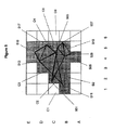
次に、図4の作動のより詳細な説明を図5への参照も行いながら提供することにする。図5は、表示されるいくつかの三角形状を示している。各三角形状は、プリミティブ又は単純に形状として公知である。画面は、30個のタイルに分割される。プリミティブは、2つのプリミティブオブジェクトに分割される。第1のプリミティブオブジェクトは、頂点501,503,505,507,及び509を有する。第2のプリミティブオブジェクトは、頂点511,513,515,517,及び519を有する。すなわち、各プリミティブオブジェクトは、いくつかのプリミティブを含む。
A more detailed description of the operation of FIG. 4 will now be provided with reference to FIG. FIG. 5 shows some triangular shapes that are displayed. Each triangle shape is known as a primitive or simply shape. The screen is divided into 30 tiles. The primitive is divided into two primitive objects. The first primitive object has
第1段階では、頂点及びプリミティブのデータが入力される(401において)。図5における三角形は、頂点501から509及び頂点511から519を有する2つのプリミティブオブジェクトへとグループ分けされる。プリミティブオブジェクトの各々は、MTE403により、メモリ空間を適切に割り当てるDPM411を用いてメモリ内に書き込まれ、メモリアドレスは、次のタイル分割段階へと渡される。
In the first stage, vertex and primitive data is input (at 401). The triangles in FIG. 5 are grouped into two primitive
第2段階では、MTEは、頂点501から509及び頂点511から519を画面空間内へと不可視であるあらゆる頂点(この事例では存在しない)を画面外として除去しながら処理する。既に解説したように、プリミティブ及び頂点データをフェッチする上でメモリ帯域幅の影響を最小にするために、プリミティブは、マクロタイル内のプリミティブオブジェクトへとグループ分けされる。一般的に、各マクロタイルは、画面サイズの4分の1又は16分の1である。プリミティブオブジェクトがマクロタイルと交差する場合には、これらのプリミティブオブジェクトのデータは、全体リストに一度だけ書き込むことができる。従って、403では、プリミティブオブジェクト(最大数の頂点を有する)は、マクロタイルに関連付けられたメモリ409の一部に書き込まれる。各マクロタイルに関連付けられたメモリページは、要求に応じてDPM411によって割り当てられる。頂点及びプリミティブの数は、プリミティブオブジェクトのメモリアドレス(これらは、頂点ポインタとして公知である)と共にTE405に送られて、プリミティブオブジェクトが可視であるタイルの制御ストリームに適用される。
In the second stage, the MTE processes
第3段階では、TE405は、制御データを各タイルに書き込む。MTE403において書き込まれるプリミティブオブジェクトからの各プリミティブは、プリミティブオブジェクトの境界ボックスの内側にある各タイルと照合される。タイル内でいずれか可視のプリミティブが存在する場合には、制御データは、そのタイルに関連付けられた制御ストリームに書き込まれる。従って、図5における頂点501から509を有する第1のプリミティブでは、このプリミティブオブジェクトに関連付けられた制御データは、C1及びC6のようなタイルではなく、C2,C3,C4,及びC5(陰付き灰色の)のようなタイルのうちの一部にのみ書き込まれる。同様に、図5における頂点511から519を有する第2のプリミティブオブジェクトでは、制御データは、B4及びB5のようなタイルのうちの一部に対して書き込まれ、B6のような他のものには書き込まれない。この段階で書き込まれる制御データは、プリミティブオブジェクト内の頂点及びプリミティブの数に関するプリミティブオブジェクトヘッダ、及び書き込まれるプリミティブオブジェクトのメモリアドレスへの頂点ポインタを含む。DPM411による制御ストリームでは、別々のメモリ空間が、各タイルに割り当てられる。
In the third stage, the
最終的に、第4段階では、ISP407によって3D画像処理が実施される。3D処理は、画面内の各タイルに対して実施される。タイル分割のためのデータ構造の概要を示している図6を参照すると、3D処理は、領域アレイ601からの各タイルに対して実施される。各タイルに対する制御データは、図6におけるいくつかの制御ストリーム0からMを含む。各制御ストリームは、プリミティブオブジェクトヘッダ及び頂点ポインタを含み、各タイルに対する制御データ内の制御ストリーム数は、各タイル内に収まるプリミティブオブジェクトの数に依存する。ISPは、各タイル603の制御ストリームを通して全探索を行い、制御データ605内の頂点ポインタによってメモリアドレスから頂点及びプリミティブのデータを読み取る。従って、図5を再度参照すると、タイルの一部は、いかなるプリミティブも含まず、B2のような一部のタイルは、1つのプリミティブオブジェクトだけからのプリミティブを含み、C2及びC3のような他のタイルは、両方のプリミティブオブジェクトからのプリミティブを含む。隠れ面除去、テクスチャリング、及びシェーディングのような画像処理作動は、タイル内で有効なプリミティブオブジェクトからの全てのプリミティブに対して実施される。
Finally, in the fourth stage, 3D image processing is performed by the
上述の公知の構成は、多くの利点を有するが、一部の欠点を確かに有する。タイル分割システムは、制御データに関するメモリ書込みが1つの制御ストリームから別のものへとジャンプするように、各タイル内のプリミティブオブジェクトを処理する。これは、メモリバーストサイズを突破し、メモリアクセスの効率を低下させる。
また、大きいプリミティブ形状が画面上のタイルの多くを覆う時には、制御データは、多数回繰り返される。特定のメモリブロック内の頂点及びプリミティブのデータは、3D画像処理中に多くのタイルに対して多数回読み取られる可能性がある。この繰返しによってメモリ帯域幅が拡大する。一方、所定のタイル内で、プリミティブオブジェクトからの頂点及びプリミティブのうちの一部だけしか可視ではなかった場合には、プリミティブオブジェクトデータ全体をフェッチするのは効率的ではない。
While the known arrangements described above have many advantages, they do have some drawbacks. The tile partitioning system processes the primitive objects in each tile so that memory writes for control data jump from one control stream to another. This breaks through the memory burst size and reduces the efficiency of memory access.
Also, when the large primitive shape covers many of the tiles on the screen, the control data is repeated many times. Vertex and primitive data in a particular memory block may be read multiple times for many tiles during 3D image processing. This repetition increases the memory bandwidth. On the other hand, if only some of the vertices and primitives from the primitive object are visible within a given tile, it is not efficient to fetch the entire primitive object data.
マクロタイルに対して頂点及びプリミティブのデータに向けて用いられるメモリページは、要求に応じて割り当てられ、従って、必ずしも連続したページであるわけではない。特定のプリミティブオブジェクトからのデータがページ境界と交差するのを防ぐために、現在のページ上にプリミティブオブジェクト全体に対する十分な空間が存在しない場合には、空き記憶領域からの新しいページが割り当てられる必要がある。この割り当てによって浪費が生じる。また、パイプラインシステムでは、プリミティブオブジェクトの正確なサイズは、オブジェクト全体が実際に書き込まれるまでは既知ではなく、従って、開始時点で最大サイズを仮定する必要がある。この仮定によって更に別の浪費が生じる。 The memory pages used for vertex and primitive data for a macro tile are allocated on demand and are therefore not necessarily contiguous pages. To prevent data from a particular primitive object from crossing a page boundary, a new page from free storage needs to be allocated if there is not enough space for the entire primitive object on the current page . This allocation is wasteful. Also, in a pipeline system, the exact size of a primitive object is not known until the entire object is actually written, so a maximum size must be assumed at the start. This assumption causes another waste.
図2を参照して冒頭で解説した部分レンダリングでは、圧縮/解凍ユニット211が、zデータを圧縮してそれをメモリ209内に書込み始める時に、タイルに関する圧縮zデータのサイズが既知ではない点で類似の問題が存在する。タイルに関する圧縮データがメモリページと交差するのを回避するために、圧縮/解凍ユニット211は、タイルの開始時点に現在のメモリページ内に十分な空間が存在するか否かを検査する必要がある。この検査は、圧縮zデータに対して最大サイズを仮定する必要があり、それによって浪費が生じる。
In the partial rendering described at the beginning with reference to FIG. 2, when the compression /
本発明者は、上述の公知のシステムに様々な改善を加えることができると考えられることを見出した。 The present inventor has found that various improvements can be added to the above-described known system.
本発明の第1の態様により、生成される画像が少なくとも1つの形状を各々含む複数のオブジェクトを含む3次元コンピュータ画像を生成する方法を提供し、本方法は、a)画像を複数の矩形区域に細分割し、各矩形区域を複数の小区域に細分割する段階と、b)画像内のオブジェクトの少なくとも一部に対して、オブジェクト内の各形状に関する面データ及び頂点データと、面データと頂点データの間のポインタとを含むオブジェクトデータをメモリに記憶する段階と、c)画像内の各小区域に対して、i)段階b)で記憶されたオブジェクトデータから、2つ又はそれよりも多くのオブジェクトに関するオブジェクトデータを抽出する段階、ii)画像内の小区域のうちのどれが、段階i)でオブジェクトデータが抽出されたオブジェクトのうちの1つ又は全てを含むかを計算する段階、iii)段階ii)で計算された小区域の各々に対して、小区域内に含まれるオブジェクト又はその各々に関するオブジェクトデータにリンクする制御データセットを導出する段階、及びiv)b)における全てのオブジェクトに対して制御データが導出されるまで段階i)からiii)を繰り返す段階によって小区域内の各オブジェクトに関するオブジェクトデータにリンクする制御データを導出する段階と、d)制御データ及びオブジェクトデータから各矩形区域に関する深度データを導出する段階と、e)表示に向けて深度データから画像データ及びシェーディングデータを導出する段階とを含む。 According to a first aspect of the present invention, there is provided a method for generating a three-dimensional computer image including a plurality of objects, each of which the generated image includes at least one shape, the method comprising: a) a plurality of rectangular areas B) subdividing each rectangular area into a plurality of sub-areas; b) for at least part of the object in the image, surface data and vertex data for each shape in the object, surface data; Storing object data in memory, including pointers between vertex data, c) for each sub-region in the image, i) from the object data stored in step b), two or more Extracting object data for many objects, ii) which of the sub-regions in the image is the object from which the object data was extracted in step i) Calculating whether to include one or all of the following: iii) for each of the subregions calculated in step ii), a control data set linked to the objects contained in the subregions or to object data relating to each Deriving control data linked to the object data for each object in the subregion by deriving and iv) repeating steps i) to iii) until control data is derived for all objects in b) And d) deriving depth data for each rectangular area from the control data and object data, and e) deriving image data and shading data from the depth data for display.
制御データは、2つ又はそれよりも多くのオブジェクトから一度に導出されるので、メモリアクセスが改善される。段階iii)で導出される各制御データセットは、段階i)でオブジェクトデータが抽出された小区域内に含まれる全てのオブジェクトのオブジェクトデータへのリンクを含む。
好ましくは、段階iii)で導出された各制御データセットにおける最終メモリ位置に、小区域に関する次の制御データセットへのポインタが設けられ、最終メモリ位置は、キャッシュに記憶される。すなわち、制御データは、段階i)でオブジェクトデータが抽出された小区域内に含まれる全てのオブジェクトのオブジェクトデータへのリンクを含むことになるので、この小区域内に収まる1つよりも多くのオブジェクトが存在したとしても、キャッシュは、一度アクセスするだけでよい。
Since control data is derived from two or more objects at once, memory access is improved. Each control data set derived in step iii) includes a link to the object data for all objects contained in the subregion from which the object data was extracted in step i).
Preferably, the final memory location in each control data set derived in step iii) is provided with a pointer to the next control data set for the subregion, and the final memory location is stored in the cache. That is, the control data will contain links to the object data of all objects contained in the sub-region from which the object data was extracted in step i), so that more than one object that fits in this sub-region Even if it exists, the cache need only be accessed once.
一実施形態では、段階b)は、画像の全てのオブジェクトに対してオブジェクトデータをメモリに記憶する段階を含む。これは、記憶される全てのオブジェクトデータに対して十分なメモリ空間が存在する場合のことである。 In one embodiment, step b) includes storing object data in memory for all objects of the image. This is the case when there is sufficient memory space for all stored object data.
代替実施形態では、段階b)は、画像内の所定数のオブジェクトに対してオブジェクトデータをメモリに記憶する段階を含み、本方法は、画像内の全てのオブジェクトに対してオブジェクトデータを記憶し終わるまで、段階e)の前に段階b)、段階c)、及び段階d)を繰り返す段階を更に含む。所定数は、利用可能メモリサイズによって判断することができる。
1つの好ましい実施形態では、段階i)は、段階b)で記憶されたオブジェクトデータから2つのオブジェクトに関するオブジェクトデータを抽出する段階を含む。
In an alternative embodiment, step b) includes storing object data in memory for a predetermined number of objects in the image, and the method finishes storing object data for all objects in the image. Further includes repeating steps b), c), and d) before step e). The predetermined number can be determined by the available memory size.
In one preferred embodiment, step i) includes extracting object data for two objects from the object data stored in step b).
本発明の第1の態様により、生成される画像が少なくとも1つの形状を各々含む複数のオブジェクトを含む3次元コンピュータ画像を生成するための装置も提供し、装置は、a)画像を複数の矩形区域に細分割し、各矩形区域を複数の小区域に細分割するための手段と、b)画像内のオブジェクトの少なくとも一部に対して、オブジェクト内の各形状に関する面データ及び頂点データと、面データと頂点データの間のポインタとを含むオブジェクトデータをメモリに記憶するための手段と、c)画像内の各小区域に対して、小区域内の各オブジェクトに関するオブジェクトデータにリンクする制御データを導出するために、i)記憶するための手段によって記憶されたオブジェクトデータから、2つ又はそれよりも多くのオブジェクトに関するオブジェクトデータを抽出し、ii)画像内の小区域のうちのどれが、オブジェクトデータが抽出されたオブジェクトのうちの1つ又は全てを含むかを計算し、iii)ii)で計算された小区域の各々に対して、小区域内に含まれるオブジェクト又はその各々に関するオブジェクトデータにリンクする制御データセットを導出し、かつiv)b)における全てのオブジェクトに対して制御データが導出されるまでi)からiii)を繰り返すように構成された導出手段と、d)制御データ及びオブジェクトデータから各矩形区域に関する深度データを導出するための手段と、e)表示に向けて深度データから画像データ及びシェーディングデータを導出するための手段とを含む。 According to a first aspect of the present invention there is also provided an apparatus for generating a three-dimensional computer image including a plurality of objects, each of which the generated image includes at least one shape, the apparatus comprising: a) a plurality of rectangles Means for subdividing into areas and subdividing each rectangular area into a plurality of subareas; b) for at least some of the objects in the image, surface data and vertex data for each shape in the object; Means for storing in the memory object data including a pointer between the face data and the vertex data; and c) for each sub-region in the image, control data linked to the object data for each object in the sub-region. To derive i) for two or more objects from the object data stored by means for storing Extract object data, ii) calculate which of the sub-regions in the image contains one or all of the extracted objects, and iii) the sub-region calculated in ii) For each of the above, a control data set is derived that links to the objects contained in the subregion or object data for each of them, and iv) from i) until control data is derived for all objects in b) iii) deriving means configured to repeat; d) means for deriving depth data for each rectangular area from the control data and object data; e) image data and shading data from the depth data for display. Means for deriving.
本発明の第2の態様により、生成される画像が複数のオブジェクトを含む3次元コンピュータ画像を生成する方法を提供し、本方法は、a)画像を複数の個別区域に細分割する段階と、b)画像内のオブジェクトの少なくとも一部に対して、オブジェクトデータをメモリに記憶する段階と、c)一度に2つの個別区域に対して、2つの個別区域内のオブジェクトデータにリンクする制御データを導出する段階と、d)i)制御データ及びオブジェクトデータから第1の個別区域に関する深度データを導出し、更に、表示に向けて深度データから第1の個別区域に関する画像データ及びシェーディングデータを導出し、かつii)制御データ及びオブジェクトデータから第2の個別区域に関する深度データを導出し、更に、表示に向けて深度データから第2の個別区域に関する画像データ及びシェーディングデータを導出することを並行して行うことにより、2つの個別区域内に3次元コンピュータ画像を生成する段階と、e)全ての個別区域に対して画像が生成されるまで段階c)及び段階d)を繰り返す段階とを含む。 According to a second aspect of the present invention, there is provided a method for generating a three-dimensional computer image in which the generated image includes a plurality of objects, the method comprising: a) subdividing the image into a plurality of individual areas; b) storing object data in memory for at least some of the objects in the image; and c) for two separate areas at a time, control data linked to the object data in the two separate areas. And d) i) deriving depth data relating to the first individual area from the control data and object data, and further deriving image data and shading data relating to the first individual area from the depth data for display. And ii) deriving depth data relating to the second individual area from the control data and object data, and for further display the depth data for display. Generating a three-dimensional computer image in the two individual areas by concurrently deriving image data and shading data for the second individual area from the data, and e) for all the individual areas Repeating steps c) and d) until an image is generated.
d)において2つの個別区域が並行して処理されるので、処理は、より迅速に達成される。
各個別区域は、好ましくは、矩形である。2つの個別区域は、好ましくは、1つが左に、1つが右に隣接する矩形の個別区域である。
1つの好ましい実施形態では、各オブジェクトは、複数の頂点を有する複数の形状を含み、段階c)で導出された制御データは、各オブジェクトに対して、オブジェクトのどの形状が個別区域のうちのどれに収まるかに関する指示、及びオブジェクトのどの頂点が個別区域のうちのどれに収まるかに関する指示を含む。
形状及び頂点が何処に収まるかというこの指示は、深度データが導出される時に、処理されている個別区域内に実際に収まらない形状又は頂点に関するデータを取得するいかなる不要なデータフェッチも存在しないことを意味する。
Processing is achieved more quickly because in d) two separate areas are processed in parallel.
Each individual area is preferably rectangular. The two individual areas are preferably rectangular individual areas, one adjacent to the left and one adjacent to the right.
In one preferred embodiment, each object includes a plurality of shapes having a plurality of vertices, and the control data derived in step c) indicates for each object which shape of the object is which of the individual areas. And instructions on which vertices of the object fit into which of the individual areas.
This indication of where the shape and vertices fit is that there is no unnecessary data fetch to obtain data about the shape or vertices that do not actually fit within the individual area being processed when depth data is derived Means.
一実施形態では、制御データは、ヘッダ部分及びペイロード部分を含む。好ましくは、ヘッダ部分は、オブジェクトのどの頂点が個別区域のうちのどれに収まるかに関する指示を含む。
好ましくは、オブジェクトの形状のうちの一部が、個別区域の各々に収まるか、又はオブジェクトの形状のうちの全てが、個別区域のうちの1つのみに収まる場合には、ペイロードは、オブジェクトのどの形状が個別区域のうちのどれに収まるかに関する指示を含む。
In one embodiment, the control data includes a header portion and a payload portion. Preferably, the header portion includes an indication as to which vertex of the object fits into which of the individual areas.
Preferably, if a portion of the object's shape fits in each of the individual areas, or if all of the object's shape fits in only one of the individual areas, the payload is Includes instructions on which shapes fit into which of the individual areas.
本発明の第2の態様により、生成される画像が複数のオブジェクトを含む3次元コンピュータ画像を生成するための装置も提供し、装置は、a)画像を複数の個別区域に細分割するための手段と、b)画像内のオブジェクトの少なくとも一部に対して、オブジェクトデータをメモリに記憶するための手段と、c)一度に2つの個別区域に対して、2つの個別区域内のオブジェクトデータにリンクする制御データを導出するための導出手段と、d)2つの個別区域内に3次元コンピュータ画像を生成するための第1の画像発生器を第2の画像発生器と並列に備える画像発生器とを含み、第1の画像発生器は、第1の個別区域に対して、制御データ及びオブジェクトデータから深度データを導出し、更に、表示に向けて深度データから第1の個別区域に関する画像データ及びシェーディングデータを導出するように構成され、第2の画像発生器は、第2の個別区域に対して、制御データ及びオブジェクトデータから深度データを導出し、更に、表示に向けて深度データから第2の個別区域に関する画像データ及びシェーディングデータを導出するように構成される。 According to a second aspect of the present invention, there is also provided an apparatus for generating a three-dimensional computer image in which the generated image includes a plurality of objects, the apparatus for a) subdividing the image into a plurality of individual areas. Means, b) means for storing object data in memory for at least some of the objects in the image, and c) object data in two separate areas for two separate areas at once. Deriving means for deriving control data to be linked; and d) an image generator comprising a first image generator in parallel with the second image generator for generating a three-dimensional computer image in two separate areas. The first image generator derives depth data from the control data and object data for the first individual area and further from the depth data for display. The second image generator is configured to derive depth data from the control data and object data for a second individual area, and further for display. It is configured to derive image data and shading data for the second individual area from the depth data.
本発明の第3の態様により、生成される画像が複数のオブジェクトを含む3次元コンピュータ画像を生成する方法を提供し、本方法は、a)画像を複数の個別区域に細分割する段階と、b)画像内のオブジェクトの少なくとも一部に対して、第1のエンジンが、メモリページに分割されているメモリにオブジェクトデータを記憶する段階と、c)b)でオブジェクトデータが記憶された各オブジェクトに対して、オブジェクトデータが1つのメモリページ上に記憶された場合に、第1のエンジンが、このメモリページアドレスを第2のエンジンに送る段階、又はオブジェクトデータが2つのメモリページ上に記憶された場合に、第1のエンジンが、これらのメモリページアドレスを第2のエンジンに送る段階と、d)画像内の各個別区域に対して、第2のエンジンが、b)で記憶されたオブジェクトデータが1つのメモリページ上に記憶された場合に1つのメモリページアドレスを含み、b)で記憶されたオブジェクトデータが2つのメモリページ上に記憶された場合に2つのメモリページアドレスを含む、小区域内の各オブジェクトに関するオブジェクトデータにリンクする制御データを導出する段階と、e)各個別区域に対して、制御データ及びオブジェクトデータから深度データを導出する段階と、f)表示に向けて深度データから画像データ及びシェーディングデータを導出する段階とを含む。 According to a third aspect of the present invention, there is provided a method for generating a three-dimensional computer image in which the generated image includes a plurality of objects, the method comprising: a) subdividing the image into a plurality of individual areas; b) a step in which the first engine stores object data in a memory divided into memory pages for at least some of the objects in the image; and c) each object in which the object data is stored in b). In contrast, if the object data is stored on one memory page, the first engine sends this memory page address to the second engine, or the object data is stored on two memory pages. The first engine sends these memory page addresses to the second engine, and d) for each individual area in the image. The second engine includes one memory page address when the object data stored in b) is stored on one memory page, and the object data stored in b) is on two memory pages. Deriving control data linked to the object data for each object in the sub-area, including two memory page addresses when stored in e), and e) depth data from the control data and object data for each individual area F) deriving image data and shading data from the depth data for display.
オブジェクトが2つのメモリページに記憶されることは、データが2つのページにわたって延びる(データが複写されるのではなく)ことを意味する。b)において記憶されるオブジェクトデータは、単一のメモリページ上、又は2つのメモリページにわたって記憶することができるのでメモリ浪費が低減する。2つのメモリページアドレスが制御データ内に含まれるので、画像が処理される時に正しいメモリページを得ることができる。 The object being stored in two memory pages means that the data extends over the two pages (rather than the data is copied). The object data stored in b) can be stored on a single memory page or across two memory pages, thus reducing memory waste. Since two memory page addresses are included in the control data, the correct memory page can be obtained when the image is processed.
本方法は、メモリマネージャが、メモリのページを画像内のオブジェクトに割り当てる段階を更に含む。この場合、メモリマネージャは、2つのメモリページを各オブジェクトに自動的に割り当てることができる。実際に、オブジェクトデータが1つのメモリページしか必要としない場合には、第2のメモリページは、単純に次のオブジェクトデータセットに向けて用いられる。
好ましくは、深度データを導出する段階e)は、個別区域内の各オブジェクトに関するオブジェクトデータにリンクする制御データが1つ又は2つのいずれのメモリページアドレスを含むか否かを判断する段階を含む。
The method further includes the step of the memory manager assigning a page of memory to the object in the image. In this case, the memory manager can automatically allocate two memory pages to each object. In fact, if the object data requires only one memory page, the second memory page is simply used for the next object data set.
Preferably, deriving depth data e) includes determining whether the control data linked to the object data for each object in the individual area includes one or two memory page addresses.
本発明の第3の態様により、生成される画像が複数のオブジェクトを含む3次元コンピュータ画像を生成するための装置も提供し、装置は、a)画像を複数の個別区域に細分割するための手段と、b)画像内のオブジェクトの少なくとも一部に対して、オブジェクトデータをメモリに記憶するための第1のエンジンと、c)小区域内の各オブジェクトに関するオブジェクトデータにリンクする制御データを導出するための第2のエンジンと、d)各個別区域に対して、制御データ及びオブジェクトデータから深度データを導出するための手段と、f)表示に向けて深度データから画像データ及びシェーディングデータを導出するための手段とを含み、メモリは、メモリページに分割され、第1のエンジンは、オブジェクトデータが記憶された各オブジェクトに対して、i)オブジェクトデータが1つのメモリページ上に記憶された場合に、このメモリページアドレスを第2のエンジンに送り、かつii)オブジェクトデータが2つのメモリページ上に記憶された場合に、これらのメモリページアドレスを第2のエンジンに送り、制御データは、第1のエンジンによって記憶されたオブジェクトデータが1つのメモリページ上に記憶された場合に、1つのメモリページアドレスを含み、第1のエンジンによって記憶されたオブジェクトデータが2つのメモリページ上に記憶された場合に、2つのメモリページアドレスを含む。 According to a third aspect of the present invention, there is also provided an apparatus for generating a three-dimensional computer image in which the generated image includes a plurality of objects, the apparatus for a) subdividing the image into a plurality of individual areas. Means, b) a first engine for storing object data in memory for at least some of the objects in the image, and c) deriving control data linked to the object data for each object in the subregion. A second engine for d) for each individual area, means for deriving depth data from the control data and object data, and f) deriving image data and shading data from the depth data for display. And the memory is divided into memory pages and the first engine stores object data For an object, i) if the object data is stored on one memory page, send this memory page address to the second engine, and ii) if the object data is stored on two memory pages These memory page addresses are sent to the second engine, and the control data includes one memory page address when the object data stored by the first engine is stored on one memory page; When the object data stored by the first engine is stored on two memory pages, it includes two memory page addresses.
装置は、メモリのページを画像内のオブジェクトに割り当てるためのメモリマネージャを更に含むことができる。メモリマネージャは、2つのメモリページを各オブジェクトに自動的に割り当てるように構成することができる。
好ましくは、深度データを導出するための手段は、個別区域内の各オブジェクトに関するオブジェクトデータにリンクする制御データが1つ又は2つのいずれのメモリページアドレスを含むか否かを判断するように構成される。
The apparatus can further include a memory manager for allocating pages of memory to objects in the image. The memory manager can be configured to automatically allocate two memory pages to each object.
Preferably, the means for deriving depth data is configured to determine whether the control data linked to the object data for each object in the individual area includes either one or two memory page addresses. The
本発明の第3の態様により、生成される画像が複数のオブジェクトを含む3次元コンピュータ画像を生成する方法も提供し、本方法は、a)画像を複数の個別区域に細分割する段階と、b)メモリページに分割され、かつルックアップテーブルを含むメモリを準備する段階と、c)メモリマネージャが、ルックアップテーブル内の2つ又はそれよりも多くの連続部分を各個別区域に割り当て、ルックアップテーブル内の各割り当てられた部分が、その個別区域に関するオブジェクトデータを記憶するために利用可能なメモリページを指し示す段階と、d)画像内のオブジェクトの少なくとも一部に対して、第1のエンジンが、各個別区域に関するオブジェクトデータを段階c)でその個別区域に割り当てられたメモリページに記憶する段階と、e)各個別区域に対して、第1のエンジンが、ルックアップテーブル内の2つ又はそれよりも多くの割り当て部分のメモリアドレスを第2のエンジンに送る段階と、f)画像内の各個別区域に対して、第2のエンジンが、第1のエンジンから送られたメモリアドレスを用いて、小区域内の各オブジェクトに関するオブジェクトデータにリンクする制御データを導出する段階と、g)画像内の各個別区域に対して、第1のエンジンから送られたメモリアドレスを用いて、制御データ及びオブジェクトデータから深度データを導出する段階と、h)表示に向けて深度データから画像データ及びシェーディングデータを導出する段階とを含む。 According to a third aspect of the present invention, there is also provided a method for generating a three-dimensional computer image in which the generated image includes a plurality of objects, the method comprising: a) subdividing the image into a plurality of individual areas; b) preparing a memory divided into memory pages and including a lookup table; c) a memory manager assigns two or more consecutive parts in the lookup table to each individual area, Each assigned portion in the uptable points to a memory page available to store object data for that individual area; and d) a first engine for at least some of the objects in the image. Storing object data for each individual area in a memory page assigned to that individual area in step c); e) For each individual area, the first engine sends the memory addresses of two or more allocated portions in the lookup table to the second engine; and f) each individual in the image. For the area, the second engine uses the memory address sent from the first engine to derive control data that links to the object data for each object in the subarea; and g) each in the image Deriving depth data from the control data and object data using the memory address sent from the first engine for the individual area; and h) deriving image data and shading data from the depth data for display. A stage of performing.
各個別区域に割り当てられた連続部分を有するルックアップテーブルを用いることにより、この個別区域に関するオブジェクトデータが記憶される実際のメモリページは、連続のものである必要はない。これは、メモリページが必ずしも連続するわけではない場合であっても、オブジェクトデータが2つのメモリページに及ぶことができることを意味する。それによってメモリ使用量が改善され、浪費が低減する。本明細書では、順序又は一連における次のものを意味するのに「連続」という用語を用いており、すなわち、ルックアップテーブル内の2つ又はそれよりも多い連続部分は、ルックアップテーブル内で一方が他方に続く隣接部分である。 By using a look-up table with a contiguous portion assigned to each individual area, the actual memory page where object data for this individual area is stored need not be contiguous. This means that object data can span two memory pages even if the memory pages are not necessarily contiguous. This improves memory usage and reduces waste. In this specification, the term “continuous” is used to mean the next in a sequence or series, ie two or more consecutive parts in a lookup table are One is an adjacent part following the other.
本発明の第3の態様により、生成される画像が複数のオブジェクトを含む3次元コンピュータ画像を生成するための装置も提供し、装置は、a)画像を複数の個別区域に細分割するための手段と、b)メモリページに分割され、かつルックアップテーブルを含むメモリと、c)ルックアップテーブル内の各割り当てられた部分が、その個別区域に関するオブジェクトデータを記憶するのに利用可能なメモリページを指し示し、ルックアップテーブル内の2つ又はそれよりも多くの連続部分を各個別区域に割り当てるためのメモリマネージャと、d)各個別区域に対して、画像内のオブジェクトの少なくとも一部に関するオブジェクトデータをメモリマネージャによってその個別区域に割り当てされたメモリページに記憶するように構成された第1のエンジンと、e)各個別区域に対して、ルックアップテーブル内の2つ又はそれよりも多くの割り当てられた部分のメモリアドレスを第1のエンジンから受け取るように構成され、更に、メモリアドレスを用いて、その個別区域内の各オブジェクトに関するオブジェクトデータにリンクする制御データを導出するように構成された第2のエンジンと、g)メモリアドレスを用いて、画像内の各個別区域に関する制御データ及びオブジェクトデータから深度データを導出するための手段と、h)表示に向けて深度データから画像データ及びシェーディングデータを導出するための手段とを含む。 According to a third aspect of the present invention, there is also provided an apparatus for generating a three-dimensional computer image in which the generated image includes a plurality of objects, the apparatus for a) subdividing the image into a plurality of individual areas. Means, b) a memory divided into memory pages and including a look-up table, and c) a memory page where each assigned portion in the look-up table is available to store object data for that individual area A memory manager for assigning two or more consecutive parts in the lookup table to each individual area; and d) object data for at least a portion of the objects in the image for each individual area Configured to store in a memory page assigned to that individual area by the memory manager E) an engine, and e) for each individual area, configured to receive memory addresses of two or more allocated parts in the lookup table from the first engine, and A second engine configured to derive control data linked to object data for each object in the individual area, and g) control data for each individual area in the image using a memory address And means for deriving depth data from the object data, and h) means for deriving image data and shading data from the depth data for display.
本発明の第4の態様により、生成される画像が複数のオブジェクトを含む3次元コンピュータ画像を生成する方法を提供し、本方法は、a)画像を複数の個別区域に細分割する段階と、b)画像内のオブジェクトの少なくとも一部に対して、オブジェクトデータを第1のメモリに記憶する段階と、c)オブジェクトデータから各個別区域に関する深度データを導出する段階と、d)各々がリンク部分として割り当てられた部分を含む複数のメモリページを含む、深度データを記憶するための第2のメモリを準備する段階と、e)個別区域に関する深度データが1つのメモリページ上に記憶された場合に、そうであることをこのメモリページのリンク部分内に示し、個別区域に関する深度データが1つよりも多くのメモリページ上に記憶された場合に、この個別区域に対する各メモリページのリンク部分を用いて、この個別区域に対する次のメモリページを指し示す、各個別区域に関する深度データを第2のメモリに記憶する段階と、f)更に別のオブジェクトデータを第1のメモリ内にロードして、既存の内容のうちの少なくとも一部を置換する段階と、g)各個別区域に対して、この個別区域に対する上述の又は各メモリページのリンク部分を読み取ることにより、記憶された深度データを取り出す段階と、h)新しいオブジェクトデータ及び記憶された深度データから最新の深度データを導出し、最新の深度データを記憶して過去に記憶された深度データを置換する段階と、i)メモリ内にロードされる更なるオブジェクトデータがなくなるまで段階e)、段階f)、段階g)、及び段階h)を繰り返す段階と、j)表示に向けて深度データから画像データ及びシェーディングデータを導出する段階とを含む。 According to a fourth aspect of the present invention, there is provided a method for generating a three-dimensional computer image in which the generated image includes a plurality of objects, the method comprising: a) subdividing the image into a plurality of individual areas; b) storing object data in a first memory for at least some of the objects in the image; c) deriving depth data for each individual area from the object data; and d) each link portion Providing a second memory for storing depth data, including a plurality of memory pages including a portion allocated as: e) depth data for an individual area is stored on a single memory page , Indicating that this is the case in the link portion of this memory page, and the depth data for the individual area was stored on more than one memory page And storing the depth data for each individual area in a second memory using the link portion of each memory page for this individual area to point to the next memory page for this individual area; f) Loading the object data into the first memory and replacing at least a part of the existing content; g) for each individual area, the link portion of the above or each memory page for this individual area Retrieving the stored depth data by reading, h) Deriving the latest depth data from the new object data and the stored depth data, storing the latest depth data and storing the depth data stored in the past And i) steps e), f), and g) until no more object data is loaded into memory. And repeating steps h), and deriving the image data and shading data from the depth data toward j) display.
本発明の第4の態様により、生成される画像が複数のオブジェクトを含む3次元コンピュータ画像を生成するための装置も提供し、装置は、a)画像を複数の個別区域に細分割するための手段と、b)画像内のオブジェクトの少なくとも一部に関するオブジェクトデータを記憶するための第1のメモリと、c)オブジェクトデータから各個別区域に関する深度データを導出するための手段と、d)各々がリンク部分として割り当てられた部分を含む複数のメモリページを含む、深度データを記憶するための第2のメモリと、e)個別区域に関する深度データが1つのメモリページ上に記憶された場合に、そうであることをこのメモリページのリンク部分内に示し、個別区域に関する深度データが1つよりも多くのメモリページ上に記憶された場合に、この個別区域に対する各メモリページのリンク部分を用いて、この個別区域に対する次のメモリページを指し示す、各個別区域に関する深度データを第2のメモリに記憶するための手段と、f)更に別のオブジェクトデータを第1のメモリ内にロードして、既存の内容のうちの少なくとも一部を置換するための手段と、g)各個別区域に対して、この個別区域に対する上述の又は各メモリページのリンク部分を読み取ることにより、記憶された深度データを取り出すための手段と、h)新しいオブジェクトデータ及び記憶された深度データから最新の深度データを導出し、最新の深度データを記憶して過去に記憶された深度データを置換するための手段と、i)表示に向けて深度データから画像データ及びシェーディングデータを導出するための手段とを含む。
本発明の一態様に関連して説明した態様は、本発明の別の態様にも適用可能である。
既存のシステムは、図1から6を参照して既に説明した。
本発明の例示的な実施形態は、図7から図11を参照して以下に説明する。
According to a fourth aspect of the present invention, there is also provided an apparatus for generating a three-dimensional computer image in which the generated image includes a plurality of objects, the apparatus for a) subdividing the image into a plurality of individual areas. Means, b) a first memory for storing object data relating to at least some of the objects in the image, c) means for deriving depth data relating to each individual area from the object data, and d) each comprising: A second memory for storing depth data, including a plurality of memory pages including a portion allocated as a link portion; and e) if depth data for an individual area is stored on one memory page In the link portion of this memory page and the depth data for the individual area was stored on more than one memory page And means for storing depth data for each individual area in a second memory that uses the link portion of each memory page for this individual area to point to the next memory page for this individual area; f) Means for loading another object data into the first memory to replace at least part of the existing content; and g) for each individual area, the above or each memory for this individual area Means for retrieving the stored depth data by reading the link portion of the page; and h) deriving the latest depth data from the new object data and the stored depth data and storing the latest depth data in the past Means for substituting depth data stored in i. And i) deriving image data and shading data from the depth data for display. And means for.
The aspects described in connection with one aspect of the invention are also applicable to other aspects of the invention.
Existing systems have already been described with reference to FIGS.
Exemplary embodiments of the present invention are described below with reference to FIGS.
上述のように、本発明の第1の態様によると、制御ストリームデータを導出する方法によってメモリ使用量を改善することができる手法が達成される。ここで、第1の態様の実施形態を以下に説明する。
図4、図5、及び図6を参照して上述したように、標準的な構成では、TE405は、MTE403からプリミティブオブジェクト(各々がいくつかのプリミティブを含む)を取得し、このプリミティブオブジェクトをレンダリングするのに必要な最少タイル数を計算する。例えば、図5の第1のプリミティブオブジェクトをレンダリングするのに必要なタイルはC2,C3,C4,C5,B3,B4,B5,及びA4である。次に、この最少タイルリストは処理されて、プリミティブオブジェクトのアドレスへの頂点ポインタが、タイルに存在するプリミティブを表すプリミティブオブジェクトヘッダと共に動的割り当てメモリに制御ストリームとして書き込まれる。これを図6に示す。
As described above, according to the first aspect of the present invention, a technique capable of improving the memory usage by the method of deriving control stream data is achieved. Here, an embodiment of the first aspect will be described below.
As described above with reference to FIGS. 4, 5, and 6, in a standard configuration,
各タイルは、制御ストリームデータに向けて用いられる独自のメモリブロックを有し、これらのメモリブロックは、要求に応じてDPM411によって割り当てられる。特定のタイルに対する制御ストリームに追加される新しいデータが、DPM411によって割り当てられた現在のメモリブロックを超えることになる場合には、新しい割り当てが要求され、古い制御ストリームは、ストリームリンクを用いて新しい割り当てにリンクされる。MTE403が終了信号によってシーンの終了を示すと、全てのタイルが処理されて、有効領域内のタイルに対する制御システムが終了ワードで終了される。
Each tile has its own memory blocks used for control stream data, and these memory blocks are allocated by the
大きいプリミティブを含むプリミティブオブジェクトでは、プリミティブオブジェクトが1つよりも多くのマクロタイルを覆う時に、全体リストを用いることができるが、制御ストリームデータは、プリミティブが収まる全てのタイルに対して数回書き込まれることを必要とする可能性がある。極端な場合には、制御ストリームデータを画面上の全てのタイルに対して書き込まなければならない場合がある。制御ストリームデータのそのような繰返しは、効率的なメモリ使用をもたらさない。 For primitive objects that contain large primitives, the entire list can be used when the primitive object covers more than one macro tile, but the control stream data is written several times for every tile that fits the primitive. May be necessary. In extreme cases, control stream data may have to be written for all tiles on the screen. Such repetition of control stream data does not result in efficient memory usage.
GB060619327.0から、TEに追加された小さいキャッシュである「テールポインタキャッシュ(TPC)」を用いてメモリアクセスを改善することができることは公知である。タイル内の制御ストリームの最後のメモリ位置が記憶され、次に、メモリをアクセスする必要がある時に、「テールポインタキャッシュ」から読み取られる。それによってTEからの主メモリアクセスが低減する。TPCの付設により、必要な主メモリアクセスの回数は低減するが、1つのタイルから次のものへの制御ストリーム間の頻繁なアドレス変更は改善されない。制御ストリームの書込みは配分されるので、TPCの付設は、幅広のバスを有するメモリインタフェースに対してはそれ程有効ではない。例えば、メモリインタフェースが128ビット幅であった場合には、2つの3ビットワード制御データを各タイル内に書き込む段階は、メモリ書込みの殆どを最大バーストのものにしないことになる(32ビット×2は128ビットを大きく下回る)。この場合、128ビットのバースト書込みで有効な64ビットのみを更新するために、バースト書込みの一部をマスクする必要がある(すなわち、未使用64ビットを)。メモリモジュールにおけるこの種のマスクされたバースト書込みには、性能低下が生じる可能性がある。 From GB 060619327.0 it is known that memory access can be improved using a “tail pointer cache (TPC)”, which is a small cache added to TE. The last memory location of the control stream in the tile is stored and then read from the “tail pointer cache” when the memory needs to be accessed. This reduces main memory access from the TE. Although the addition of TPC reduces the number of main memory accesses required, frequent address changes between control streams from one tile to the next are not improved. Since the writing of the control stream is distributed, the TPC attachment is not so effective for a memory interface having a wide bus. For example, if the memory interface is 128 bits wide, writing two 3-bit word control data into each tile will not make most of the memory writes in the largest burst (32 bits × 2 Is well below 128 bits). In this case, in order to update only the valid 64 bits in a 128-bit burst write, it is necessary to mask a portion of the burst write (ie, unused 64 bits). This type of masked burst write in the memory module can cause performance degradation.
本発明のこの実施形態では、TEは、MTEから一度に2つのプリミティブオブジェクト(1つではなく)を取得する。TEは、特定のタイルに対して2つのプリミティブオブジェクトを同時に処理する。従って、各プリミティブオブジェクトを取得して、このプリミティブオブジェクトが収まるタイルの全てを通じて作業し、次に、別のプリミティブオブジェクトを取得し、以降同様に続ける代わりに、TEは、2つのプリミティブオブジェクトを一度に取得し、それによってメモリ使用量及びアクセスが改善される。 In this embodiment of the invention, the TE obtains two primitive objects (not one) at a time from the MTE. TE processes two primitive objects simultaneously for a particular tile. Thus, instead of getting each primitive object and working through all of the tiles in which this primitive object fits, then getting another primitive object, and so on, TE does not take two primitive objects at once. Obtaining, thereby improving memory usage and access.
図5を参照すると、TEは、MTEから両方のプリミティブオブジェクトを取得する。TEは、片方又は両方のプリミティブオブジェクトが収まる各タイル(この事例では陰付きタイル)に関する制御ストリームデータを順次書き込む。片方のプリミティブオブジェクトだけが収まるタイル(例えば、タイルB5)に対しては、TEは、このプリミティブオブジェクトに関する制御ストリームデータを書き込む。制御ストリームの最後では、メモリ位置が、テールポインタキャッシュ(TPC)に記憶される。両方のプリミティブオブジェクトが収まるタイル(例えば、タイルC3)に対しては、TEは、第1のプリミティブオブジェクトに関する制御ストリームデータを生成する。次に、TEは、第2のプリミティブオブジェクトに関する制御ストリームデータを生成する。このタイルにおける両方のプリミティブオブジェクトに対する制御ストリームデータは、メモリに一緒に書き込まれる。別のタイルに対して処理を続ける前に、このタイルの処理にわたる全ての処理の最後において、制御ストリームの最終メモリアドレスがTPCに記憶される。 Referring to FIG. 5, the TE gets both primitive objects from the MTE. The TE sequentially writes control stream data for each tile (in this case, a shaded tile) that contains one or both primitive objects. For tiles that contain only one primitive object (eg, tile B5), the TE writes control stream data for this primitive object. At the end of the control stream, the memory location is stored in the tail pointer cache (TPC). For tiles in which both primitive objects fit (eg, tile C3), the TE generates control stream data for the first primitive object. Next, the TE generates control stream data for the second primitive object. Control stream data for both primitive objects in this tile are written together in memory. Before continuing with another tile, at the end of all processing across this tile, the final memory address of the control stream is stored in the TPC.
この実施形態の一般的な方法を図7の流れ図に示す。タイル分割が2つのプリミティブオブジェクトに対して行われ、各プリミティブオブジェクトは、32個までの形状(プリミティブとも呼ぶ)を収容することができる。
すなわち、2つのプリミティブオブジェクトが収まるタイルでは、このタイルに関する制御ストリームの最後におけるアドレスは、従来のシステムでの2度ではなく、一度だけ読み取られる必要がある。これらのタイルに対しては、制御ストリームデータ書込みは、128ビットよりも小さい2回のマスクされた書込みではなく、128ビットの最大バースト書込みになる。TPCアクセスは、これらのタイルでは半分になる。本発明者は、一部の事例において制御ストリームデータに関する128ビットの最大バースト書込みを0%から25%に増大させることができ、一部の事例においてTPCキャッシュミスの百分率を12%から0.04%に低減することができることを見出した。
The general method of this embodiment is shown in the flowchart of FIG. Tiling is performed on two primitive objects, and each primitive object can contain up to 32 shapes (also called primitives).
That is, for a tile that contains two primitive objects, the address at the end of the control stream for this tile needs to be read only once, not twice in conventional systems. For these tiles, the control stream data write is a 128-bit maximum burst write, rather than two masked writes that are smaller than 128 bits. TPC access is halved for these tiles. The inventor can increase the 128-bit maximum burst write for control stream data from 0% to 25% in some cases and the percentage of TPC cache misses from 12% to 0.04 in some cases. It was found that it can be reduced to%.
上述の実施形態をTEがMTEから2つのプリミティブオブジェクトを一度に取得する場合で説明した。明らかに、本方法は、TEが一度に2つよりも多くのオブジェクトをMTEから取得するように拡張することができる。毎回得られるプリミティブオブジェクトの数は、レンダリングされるシーンの複雑さ、プリミティブオブジェクト自体の複雑さ(すなわち、これらのプリミティブオブジェクトがいくつの面及び頂点を含むか)、及びTEの処理機能に依存することになる。 The above embodiments have been described in the case where the TE acquires two primitive objects from the MTE at a time. Obviously, the method can be extended so that the TE gets more than two objects from the MTE at a time. The number of primitive objects obtained each time depends on the complexity of the scene being rendered, the complexity of the primitive objects themselves (ie how many faces and vertices they contain), and the processing capabilities of TE become.
上述のように、本発明の第2の態様によると、2つの等しい3D画像処理パイプが2つのタイルに対して同時に機能することを可能にすることによって3D画像発生器の性能を改善する手法が達成される。これを図8に示す。
図8は、図4の簡略化したものであり、TE、ISP、及びメモリのみを示している。TE801は、制御データをメモリ809に書き込む。3Dパラメータフェッチ803は、頂点及びプリミティブのデータを読み取って画像処理を実施する。この実施形態では、この処理は、2つのサブISP/TSP805及び807によって並行して実施される。この構成では、3D画像処理の性能は、二倍になると予想される。
図8のシステムを有効に作動させるために、TE801は、タイルのうちの2つに対して互いに制御データを書き込む。この書込みを811に略示している。本方法は、タイル分割制御ストリームデータにおける重複を大幅に低減し、従って、良好なメモリ帯域幅の改善を与える。
As mentioned above, according to the second aspect of the present invention, there is a technique for improving the performance of a 3D image generator by allowing two equal 3D image processing pipes to work simultaneously on two tiles. Achieved. This is shown in FIG.
FIG. 8 is a simplified version of FIG. 4 and shows only TE, ISP, and memory. The
To effectively operate the system of FIG. 8, the
各タイルサイズが16×16ピクセルであった場合には、TE801は、全てのプリミティブオブジェクトを元の16×16タイルにタイル分割する。しかし、TEは、制御ストリームデータ(811に示している)を32×16ピクセルのタイル、すなわち、2つの隣接する16×16タイルで書き込む。すなわち、各制御ストリームにおいて2つの16×16タイルが参照される。この2つのタイルの利点は、両方のタイル内に収まるオブジェクトを一度書き込むだけでよいので、書き込まれる制御ストリームデータの合計量が大きく低減することになる点である。一方、欠点も存在する。制御ストリームデータは、プリミティブオブジェクトの境界ボックスが、両方の16×16タイルと重なるという仮定に基づいている。プリミティブオブジェクト内には、例えば、32個までのプリミティブ及び16個までの頂点が存在する可能性があるが、これらのプリミティブ及び頂点の全てが特定の16×16タイルに収まることにはならない。プリミティブ及び頂点のうちの一部が、2つの16×16タイルのうちの片方にしか収まらない場合には、これらの無効なプリミティブ及び頂点によってパラメータデータ参照情報をフェッチして処理することは浪費になる。別の言い方をすると、2つのタイルを一度に取得することにより、最初に小さいタイルを有するという利点が幾分減少する。
If each tile size is 16 × 16 pixels, the
この実施形態では、この問題は、制御ストリーム内で頂点マスク及びプリミティブマスクを用いて解決される。制御ストリームデータは、各プリミティブオブジェクトに対して、プリミティブオブジェクトヘッダ、及びそのプリミティブオブジェクトに関するオブジェクトデータ(プリミティブ及び頂点のデータを含む)のメモリアドレスを指し示す頂点ポインタを含む。この実施形態に用いられるマスクは、各16×16タイルに対して有効な頂点及びプリミティブ、すなわち、実際にそのタイル内に収まる頂点及びプリミティブを示している。頂点マスクは、頂点数及びプリミティブ数のような他の情報と共にプリミティブオブジェクトヘッダ内に含めることができる16ビットのマスクである。頂点マスクは、各32×16タイルに対して有効な頂点を定義する。通常は、16×16タイルの各々に対して1つづつの2つの32ビットプリミティブマスクが必要である。プリミティブマスクは、各16×16タイルに対して有効なプリミティブを定義する。プリミティブマスクは、ヘッダ内に含めることができ、又は制御ストリームに追加ワードとして加えることを必要とする場合がある。この実施形態では、両方の16×16タイルに対して1つの頂点マスクだけしか必要とされず、それに対して各16×16タイルに対して1つのプリミティブマスクを必要とすることに注意されたい。これは、頂点データがバーストで読み取られ、レンダリング処理がプリミティブに基づいており、従って、少数の不要頂点を読み取るのにそれ程コストが掛からないことによる。従って、空間を節約するために、32×16タイルに対して単一の頂点マスクを用いることができる。一方、不要なプリミティブを処理するには、より多くのコストが掛かり、従って、これを回避するために、より大きな空間を必要とはするが、各16×16タイルに対してプリミティブマスクが用いられる。
プリミティブが多くのタイルに重なる時にメモリ帯域幅に対する大きな影響を回避するために、制御ストリーム内のマスクのデータサイズを最小に保つ必要がある。この実施形態は、頂点マスク及びプリミティブマスクが含まれる時に制御ストリームのサイズを縮小する符号化手法を用いる。
In this embodiment, this problem is solved using vertex masks and primitive masks in the control stream. The control stream data includes, for each primitive object, a primitive object header and a vertex pointer that points to the memory address of the object data (including primitive and vertex data) for that primitive object. The mask used in this embodiment shows valid vertices and primitives for each 16 × 16 tile, ie vertices and primitives that actually fit within that tile. The vertex mask is a 16-bit mask that can be included in the primitive object header along with other information such as the number of vertices and the number of primitives. The vertex mask defines valid vertices for each 32 × 16 tile. Typically, two 32-bit primitive masks are required, one for each 16 × 16 tile. The primitive mask defines valid primitives for each 16 × 16 tile. The primitive mask can be included in the header or may need to be added as an additional word to the control stream. Note that in this embodiment, only one vertex mask is required for both 16 × 16 tiles, whereas one primitive mask is required for each 16 × 16 tile. This is because the vertex data is read in bursts and the rendering process is based on primitives, so it is not very expensive to read a small number of unwanted vertices. Therefore, a single vertex mask can be used for 32 × 16 tiles to save space. On the other hand, processing undesired primitives is more costly and therefore requires more space to avoid this, but a primitive mask is used for each 16 × 16 tile. .
In order to avoid a significant impact on memory bandwidth when a primitive overlaps many tiles, the data size of the mask in the control stream needs to be kept to a minimum. This embodiment uses an encoding technique that reduces the size of the control stream when vertex masks and primitive masks are included.
既に解説したように、頂点マスク(及び場合によってはプリミティブマスク)は、プリミティブオブジェクトヘッダに含まれる。32ビットプリミティブオブジェクトヘッダにおける符号化手法の詳細を表1に示す。 As already explained, the vertex mask (and possibly the primitive mask) is included in the primitive object header. Table 1 shows details of the encoding method in the 32-bit primitive object header.
(表1)

表1に示しているプリミティブオブジェクトヘッダの構造を図8aに例示している。
PF_MASK_CONTROL:
プリミティブマスク制御フラグ「PF_MASK_CONTROL」に対して2ビット(20:19)が用いられる。このフラグは、制御ストリーム内の何処に頂点マスク及びプリミティブマスクが含まれるかを判断する。この符号化では、制御ストリーム内の追加プリミティブマスクワードは任意的である。
PF_MASK_CONTROL=01=PF_MASK_CTRL_PRIM_MASK_PRESである場合には、PF_MASK_CONTROLは、プリミティブマスクワードが制御ストリームに含まれることを意味する。一方、PF_MASK_CONTROL≠01である場合には、プリミティブワードは、制御ストリームに含まれず、ヘッダに含まれる。
The structure of the primitive object header shown in Table 1 is illustrated in FIG. 8a.
PF_MASK_CONTROL:
Two bits (20:19) are used for the primitive mask control flag “PF_MASK_CONTROL”. This flag determines where in the control stream the vertex mask and primitive mask are included. In this encoding, the additional primitive mask word in the control stream is optional.
When PF_MASK_CONTROL = 01 = PF_MASK_CTRL_PRIM_MASK_PRES, PF_MASK_CONTROL means that a primitive mask word is included in the control stream. On the other hand, when PF_MASK_CONTROL ≠ 01, the primitive word is not included in the control stream but is included in the header.
PF_MASK_CONTROL=01である前者の場合には、1つ又は2つのあらゆる追加プリミティブマスクワードを必要とすることができる。1つ又は2つのいずれの32ビットワードが存在するかは、PF_PRM_STARTに示されている。1つの追加プリミティブマスクワードしか持たない条件は、両方のプリミティブマスクが、下位16ビット又は上位16ビットセットのいずれかしか持たないということである。これは、両方のプリミティブオブジェクトが、左手16×16タイル又は右手16×16タイルのいずれかのみで有効であり、両方において有効ではないことを意味する。この場合、2つのプリミティブマスクワードが存在する場合は、片方は単純に0になり、従って、プリミティブワードマスクを完全に省略することができる。代替的に、両方のプリミティブオブジェクト内のプリミティブは、16×16タイルのうちの左又は右のいずれか片方においてのみ有効である。そうでなければ、2つの付加的なプリミティブマスクワードが必要とされ、これらは、2つの16×16タイル内で参照されるプリミティブに関する制御ストリームに追加される。 In the former case where PF_MASK_CONTROL = 01, one or two additional primitive mask words may be required. Whether one or two 32-bit words are present is indicated in PF_PRM_START. The condition with only one additional primitive mask word is that both primitive masks have either the lower 16 bits or the upper 16 bits set. This means that both primitive objects are valid only in either the left hand 16 × 16 tile or the right hand 16 × 16 tile, not in both. In this case, if there are two primitive mask words, one will simply be 0, so the primitive word mask can be omitted entirely. Alternatively, the primitives in both primitive objects are valid only on either the left or right side of the 16x16 tile. Otherwise, two additional primitive mask words are needed and these are added to the control stream for the primitives referenced in the two 16x16 tiles.
PF_MASK_CONTROL≠01である後者の場合を有する条件、すなわち、いずれのプリミティブワードも制御ストリームに含まれない条件は、プリミティブオブジェクト内の全てのプリミティブが現在の32×16タイル内で参照されるか(すなわち、プリミティブオブジェクト内の全てのプリミティブが両方の16×16タイル内に収まり、従って、プリミティブマスクワードの必要がない)、又はプリミティブ及び頂点の両方のマスクに対して1バイト分の非0ビットのみが存在するということである。この第2の条件は、頂点マスクワードが、1バイト分の非0ビットを有し、非0頂点マスクバイトが、PF_MASK_BYTE1内にあることを意味する。すなわち、頂点1から8が32×16タイル内で参照されないか、又は頂点9から16が32×16タイル内で参照されないかのいずれかである。(後に解説することになるが、PF_VTM_STARTが1の場合には、PF_VTM_STARTは、PF_MASK_BYTE1が頂点マスクの上位8ビットを含み、すなわち、頂点1から8が32×16タイル内で参照されないことを示している。PF_VTM_STARTが0である場合には、PF_VTM_STARTは、PF_MASK_BYTE1が頂点マスクの下位8ビットを含み、すなわち、頂点9から16は、32×16タイル内で参照されないことを示している。)PF_MASK_CONTROL≠01である場合には、PF_MASK_BYTE0内には、1バイトのプリミティブマスクしか存在せず、従って、32ビットプリミティブマスクのうちの片方が0である必要がある。すなわち、プリミティブは、16×16タイルのうちの左又は右のいずれか片方においてのみ有効である。PF_PRM_STARTにおける値は、プリミティブマスク内でのPF_MASK_BYTE0のバイトオフセットを示している。例えば、PF_PRM_START=1である場合には、32ビットプリミティブマスクは、0x0000F700のように見えることになり、バイト10×F7が、ヘッダにPF_MASK_BYTE0として挿入される。
A condition with the latter case where PF_MASK_CONTROL ≠ 01, ie, no primitive word is included in the control stream, is that all primitives in the primitive object are referenced in the current 32 × 16 tile (ie All primitives in a primitive object fit within both 16x16 tiles, so there is no need for primitive mask words), or only one non-zero bit for a primitive and vertex mask It exists. This second condition means that the vertex mask word has 1 byte of non-zero bits and the non-zero vertex mask byte is in PF_MASK_BYTE1. That is, either
PF_MASK_CONTROL≠01である後者の場合には、PF_MASK_CONTROL≠01である時に、PF_MASK_BYTE0内に詰め込まれた1バイトプリミティブマスクに対して2つの可能性が存在する。
PF_MASK_CONTROL=00(PF_MASK_CTRL_PACKED_LEFT)である場合には、プリミティブマスク及び頂点マスクは、両方共にヘッダに含まれ、PF_MASK_BYTE0内に詰め込まれた1バイトプリミティブマスクは、32×16タイルの左半分に付属する。
PF_MASK_CONTROL=11(PF_MASK_CTRL_PACKED_RIGHT)である場合には、プリミティブマスク及び頂点マスクは、両方共にヘッダに含まれ、プリミティブマスクは、32×16タイルの右半分に付属する。
すなわち、PF_MASK_CONTROLのこれらの2ビットが、00,11,又は10である場合には、制御ストリームにいかなる追加プリミティブマスクも存在しない。
In the latter case where PF_MASK_CONTROL ≠ 01, there are two possibilities for the 1-byte primitive mask packed in PF_MASK_BYTE0 when PF_MASK_CONTROL ≠ 01.
When PF_MASK_CONTROL = 00 (PF_MASK_CTRL_PACKED_LEFT), both the primitive mask and the vertex mask are included in the header, and the 1-byte primitive mask packed in PF_MASK_BYTE0 is attached to the left half of the 32 × 16 tile.
When PF_MASK_CONTROL = 11 (PF_MASK_CTRL_PACKED_RIGHT), both the primitive mask and the vertex mask are included in the header, and the primitive mask is attached to the right half of the 32 × 16 tile.
That is, if these two bits of PF_MASK_CONTROL are 00, 11, or 10, there is no additional primitive mask in the control stream.
PF_PRM_START:
プリミティブマスク開始点「PF_PRM_START」に対して2ビット(18:17)が用いられる。PF_PRM_STARTは、プリミティブマスクがヘッダに含まれるか(PF_MASK_CONTROL≠01)、又は制御ストリームに追加マスクとして含まれるか(PF_MASK_CONTROL=01)のいずれであるかに依存して別々に用いられる。
PF_MASK_CONTROL≠01である場合には、この2ビットは、プリミティブマスクがヘッダに含まれる時のプリミティブマスク内でのPF_MASK_BYTE0のバイトオフセットを示している。
PF_MASK_CONTROL=01である場合には、この2ビットは、以下の通りに制御ストリームにどの追加マスクが含まれるかを示す上で用いられる。
PF_PRM_START:
Two bits (18:17) are used for the primitive mask start point “PF_PRM_START”. PF_PRM_START is used separately depending on whether the primitive mask is included in the header (PF_MASK_CONTROL ≠ 01) or as an additional mask in the control stream (PF_MASK_CONTROL = 01).
When PF_MASK_CONTROL ≠ 01, these 2 bits indicate the byte offset of PF_MASK_BYTE0 in the primitive mask when the primitive mask is included in the header.
When PF_MASK_CONTROL = 01, these 2 bits are used to indicate which additional mask is included in the control stream as follows.
これらの2ビット、すなわち、PF_PRM_STARTが00である場合には、制御ストリームに2つの16ビットプリミティブマスクが含まれ、すなわち、左右の16×16タイルに対する32ビットプリミティブマスクの両方が、下位16ビットを0として又は上位16ビットを0として、そのいずれかで有する。PF_VTM_START=0である場合には、PF_VTM_STARTは、2つの16ビットプリミティブマスクがビット0から15におけるものであり、かつ両方の16×16タイルに対してプリミティブ1から16のみが参照されることを示している。PF_VTM_START=1である場合には、PF_VTM_STARTは、2つの16ビットプリミティブマスクがビット16から31におけるものであり、かつ両方の16×16タイルに対してプリミティブ17から32のみが参照されることを示している。
これらの2つの16ビットプリミティブマスクは、32ビットプリミティブマスクワードへと組み合わされる。これを下記の表2に示す。
If these 2 bits, ie PF_PRM_START is 00, the control stream contains two 16-bit primitive masks, ie both 32-bit primitive masks for the left and right 16 × 16 tiles have the lower 16 bits Either 0 or the upper 16 bits are set to 0. If PF_VTM_START = 0, then PF_VTM_START indicates that the two 16-bit primitive masks are at bits 0-15 and that only primitives 1-16 are referenced for both 16x16 tiles. ing. If PF_VTM_START = 1, then PF_VTM_START indicates that the two 16-bit primitive masks are at bits 16-31 and only primitives 17-32 are referenced for both 16 × 16 tiles. ing.
These two 16-bit primitive masks are combined into a 32-bit primitive mask word. This is shown in Table 2 below.
(表2)
この場合のプリミティブマスクワードの構造を図8bに示す。ビット0から15は、左手16×16タイルに対する16ビットプリミティブ半マスクのために用いられる。ビット16から31は、右手16×16タイルに対する16ビットプリミティブ半マスクのために用いられる。
2つのビット、すなわち、PF_PRM_STARTが01である場合には、左手16×16タイルに対して1つの32ビットプリミティブマスクが制御ストリームに含まれる。これを下記の表3に示す。
The structure of the primitive mask word in this case is shown in FIG. Bits 0 through 15 are used for the 16-bit primitive half mask for the left hand 16 × 16 tile. Bits 16 to 31 are used for the 16-bit primitive half mask for the right hand 16 × 16 tile.
If two bits, ie PF_PRM_START is 01, one 32-bit primitive mask is included in the control stream for the left-hand 16 × 16 tile. This is shown in Table 3 below.
(表3)
この場合のプリミティブマスクワードの構造を図8cに示す。
2つのビット、すなわち、PF_PRM_STARTが10である場合には、右手16×16タイルに対して1つの32ビットプリミティブマスクが制御ストリームに含まれる。これを下記の表4に示す。
The structure of the primitive mask word in this case is shown in FIG.
If two bits, ie PF_PRM_START is 10, one 32-bit primitive mask is included in the control stream for the right-hand 16 × 16 tile. This is shown in Table 4 below.
(表4)
この場合のプリミティブマスクワードの構造を図8dに示す。
最後に、2つのビット、すなわち、PF_PRM_STARTが11である場合には、各16×16タイルに対して1つの2つの32ビットプリミティブマスクが制御ストリームに含まれる。これを下記の表5a及び5bに示す。
The structure of the primitive mask word in this case is shown in FIG.
Finally, if the two bits, ie PF_PRM_START is 11, two 32-bit primitive masks, one for each 16 × 16 tile, are included in the control stream. This is shown in Tables 5a and 5b below.
(表5a)
(表5b)
この場合のプリミティブマスクワードの構造を図8eに示す。 The structure of the primitive mask word in this case is shown in FIG.
PF_VTM_START:
表1を再度参照すると、頂点マスク開始点「PF_VTM_START」に対して1ビット(16)が用いられる。PF_VTM_STARTは、プリミティブマスクがヘッダに含まれるか(PF_MASK_CONTROL≠01)、又は制御ストリーム内の追加マスクとして含まれるか(PF_MASK_CONTROL=01)のいずれであるかに依存して別々に用いられる。
PF_MASK_CONTROL≠01であり、すなわち、プリミティブマスクがヘッダに含まれる場合には、PF_VTM_STARTのビットが設定され、すなわち、=1である場合に、PF_VTM_STARTは、PF_MASK_BYTE1(下記に解説することになる)が、16ビット頂点マスクの上位8ビットであるバイト1を反映することを示している。このビットが消去され、すなわち、=0である場合には、PF_VTM_STARTは、PF_MASK_BYTE1が、16ビット頂点マスクの下位8ビットであるバイト0を含むことを示している。
PF_VTM_START:
Referring back to Table 1, one bit (16) is used for the vertex mask start point “PF_VTM_START”. PF_VTM_START is used separately depending on whether the primitive mask is included in the header (PF_MASK_CONTROL ≠ 01) or as an additional mask in the control stream (PF_MASK_CONTROL = 01).
If PF_MASK_CONTROL ≠ 01, that is, if the primitive mask is included in the header, the bit of PF_VTM_START is set, that is, if = 1, PF_VTM_START is PF_MASK_BYTE1 (which will be described below) It shows that
PF_MASK_CONTROL=01であり、すなわち、プリミティブマスクが制御ストリームに追加され、かつPF_PRM_START=00である場合には、PF_VTM_STARTが1である場合に、PF_VTM_STARTは、16ビットプリミティブ半マスクの両方が、プリミティブ31:16に適用されることを示している。上記以外の場合は、これらは、15:0に適用される。 If PF_MASK_CONTROL = 01, ie, a primitive mask is added to the control stream and PF_PRM_START = 00, then PF_VTM_START is 1, both PF_VTM_START are primitives 31: 16 is applied. Otherwise, these apply to 15: 0.
PF_MASK_BYTE1:
「PF_MASK_BYTE1」に対して8ビットが用いられる。PF_MASK_BYTE1は、PF_MASK_CONTROL及びPF_VTM_STARTのステータスに依存する。PF_MASK_CONTROL≠01、すなわち、プリミティブマスクが、ヘッダ内のPF_MASK_BYTE0内に含まれ、かつPF_VTM_STARTが1に等しい場合には、これらの8ビットは、16ビット頂点マスクの上位8ビットである。一方、PF_MASK_CONTROL≠01であり、かつPF_VTM_STARTが0に等しい場合には、これらの8ビットは、16ビット頂点マスクの下位8ビットである。
PF_MASK_BYTE1:
8 bits are used for “PF_MASK_BYTE1”. PF_MASK_BYTE1 depends on the status of PF_MASK_CONTROL and PF_VTM_START. If PF_MASK_CONTROL ≠ 01, that is, a primitive mask is included in PF_MASK_BYTE0 in the header and PF_VTM_START is equal to 1, these 8 bits are the upper 8 bits of the 16-bit vertex mask. On the other hand, if PF_MASK_CONTROL ≠ 01 and PF_VTM_START is equal to 0, these 8 bits are the lower 8 bits of the 16-bit vertex mask.
PF_MASK_BYTE0:
「PF_MASK_BYTE0」に対して8ビットが用いられる。PF_MASK_BYTE0は、PF_MASK_CONTROL及びPF_PRM_STARTのステータスに依存する。PF_MASK_CONTROL=01、すなわち、プリミティブマスクが、ヘッダではなく制御ストリームに含まれる場合には、16ビット頂点マスクは、PF_MASK_BYTE0及びPF_MASK_BYTE1内にあり、PF_MASK_BYTE0は、頂点マスクの下位8ビットである。一方、PF_MASK_CONTROL≠01である場合には、プリミティブマスクからの1つの非0バイトが、PF_MASK_BYTE0内にある。この場合、この非0バイトプリミティブマスクのバイトオフセットは、PF_PRM_STARTからのものである。
PF_MASK_BYTE0:
8 bits are used for “PF_MASK_BYTE0”. PF_MASK_BYTE0 depends on the status of PF_MASK_CONTROL and PF_PRM_START. If PF_MASK_CONTROL = 01, ie, the primitive mask is included in the control stream instead of the header, the 16-bit vertex mask is in PF_MASK_BYTE0 and PF_MASK_BYTE1, and PF_MASK_BYTE0 is the lower 8 bits of the vertex mask. On the other hand, if PF_MASK_CONTROL ≠ 01, one non-zero byte from the primitive mask is in PF_MASK_BYTE0. In this case, the byte offset of this non-zero byte primitive mask is from PF_PRM_START.
TEが、32×16タイル内のプリミティブオブジェクトからのプリミティブ及び頂点データを処理する場合には、TEは、オブジェクト内の全ての頂点を検査して、タイル内の有効頂点に対する頂点マスクを作成する。次に、TEは、16×16タイルの各々に収まるオブジェクト内の有効プリミティブに対するプリミティブマスクを生成する。上述の符号化手法は、次に、頂点マスク及びプリミティブマスクを制御ストリームデータ内に可能な限り小さいサイズで書き込む上で用いられる。 If the TE processes primitive and vertex data from a primitive object in a 32 × 16 tile, the TE examines all vertices in the object and creates a vertex mask for valid vertices in the tile. Next, the TE generates a primitive mask for valid primitives in the object that fit in each of the 16 × 16 tiles. The above encoding technique is then used to write the vertex mask and primitive mask in the control stream data with the smallest possible size.
制御ストリームの最後のテールポインタアドレスは、「テールポインタキャッシュ(TPC)」を通じて32×16タイルへのタイル分割の開始時点で読み戻される。テールポインタアドレスは、タイルの全ての処理が完了した後に初めて書き戻される。32×16タイルの両方の16×16タイルが、両方のプリミティブオブジェクト含む場合は(図5に戻り、例えば、タイルC3及びC4を参照されたい)、2つのプリミティブオブジェクトは、2つの16×16タイル内で処理されることになり、TPCが制御ストリームの最後に対するテールポインタで更新される前に、制御ストリームに書き込まれた適切な制御データを有する。それによって制御ストリームデータ書込みからのメモリアクセスが改善され、TPCの性能が改善される。 The last tail pointer address of the control stream is read back through the “tail pointer cache (TPC)” at the start of tile division into 32 × 16 tiles. The tail pointer address is written back only after all processing of the tile is complete. If both 16 × 16 tiles of a 32 × 16 tile contain both primitive objects (return to FIG. 5, see eg tiles C3 and C4), two primitive objects are two 16 × 16 tiles With the appropriate control data written to the control stream before the TPC is updated with the tail pointer for the end of the control stream. This improves memory access from writing control stream data and improves TPC performance.
本発明のこの実施形態では、各32×16タイルの制御ストリームが一度に処理される。32×16タイルでは、タイル内で参照される頂点は、頂点マスクを用いてメモリからフェッチされる。このフェッチは、図8のパラメータフェッチ803によって実施される。従って、タイル内で参照されないフェッチ頂点に対していかなるメモリ帯域幅も追加されず、従って、上記に解説した問題は解決される。同様に、16×16タイルの各々に対するプリミティブマスクは、プリミティブデータをフェッチするのに用いられる。このフェッチも、図8の803によって実施される。上述の場合のように、タイル内で参照されないフェッチプリミティブに対していかなるメモリ帯域幅も追加されない。次に、左手の16×16タイルに対して適切なプリミティブ及び頂点が、サブISP/TSP805に送られ、右手の16×16タイルに対して適切なプリミティブ及び頂点が、サブISP/TSP807に送られる。
In this embodiment of the invention, each 32 × 16 tile control stream is processed at once. For 32 × 16 tiles, vertices referenced in the tile are fetched from memory using a vertex mask. This fetch is performed by the parameter fetch 803 in FIG. Thus, no memory bandwidth is added for fetch vertices that are not referenced in the tile, thus solving the problem described above. Similarly, the primitive mask for each 16 × 16 tile is used to fetch primitive data. This fetch is also performed by 803 in FIG. As in the case above, no memory bandwidth is added for fetch primitives that are not referenced in the tile. The appropriate primitives and vertices for the left hand 16 × 16 tile are then sent to the sub-ISP /
本発明者は、32×16ピクセルタイルに基づくタイル分割であるこの実施形態の方法が、16×16ピクセルタイルに基づくタイル分割と比較して、付加的なプリミティブマスクワードを用いた場合でさえも平均で35%の制御ストリームデータ書込みの低減をもたらすことを見出した。3Dパラメータフェッチにおける合計のデータ読取りに対しても同等のレベルの低減を達成した。
上述のように、本発明の第3の態様によると、メモリ空間を用いるより効率的な手法が達成される。次に、第3の態様の実施形態を以下に説明する。
The inventor found that the method of this embodiment, which is a tile partition based on 32 × 16 pixel tiles, even when using additional primitive mask words compared to a tile partition based on 16 × 16 pixel tiles. It has been found to provide an average 35% reduction in control stream data writing. An equivalent level of reduction was achieved for the total data read in 3D parameter fetch.
As described above, according to the third aspect of the present invention, a more efficient approach using memory space is achieved. Next, an embodiment of the third aspect will be described below.
既に解説したように、既存のシステムでは、頂点及びプリミティブデータに対するマクロタイルに用いられるメモリページは、要求に応じて割り当てられ、従って、必ずしも連続するページであるわけではない。特定のプリミティブオブジェクトからのデータがページ境界を超えるのを防ぐために、プリミティブオブジェクト全体に対して現在のページ上に不十分な空間しか存在しない場合には、空き記憶領域から新しいページを割り当てる必要がある。 As already explained, in existing systems, the memory pages used for macrotiles for vertex and primitive data are allocated on demand and are therefore not necessarily contiguous pages. To prevent data from a particular primitive object from crossing a page boundary, a new page must be allocated from free storage if there is insufficient space on the current page for the entire primitive object .
特定のプリミティブオブジェクトに含まれる頂点及びプリミティブの最大数には制限が存在する(例えば、16個の頂点及び32個のプリミティブ)。上述のように、MTEは、プリミティブオブジェクトがメモリのページ境界に架からないことを確実にすべきである。これは、メモリページが、連続する順序で割り当てられることが保証されないからである。頂点をプリミティブオブジェクトに割り当てるパイプラインのフロントエンドは、このプリミティブオブジェクトに残されたいかなる空間量も既知ではないので、上述のことは困難である。一方、メモリを割り当て、実際にプリミティブオブジェクトデータをメモリに入力するパイプラインのバックエンドは、オブジェクト内の頂点数に対していかなる制御も持たない。現在のメモリページにプリミティブオブジェクト内の最大頂点数を保持するのに十分なメモリ空間が存在するか否かの検査が、十分な空間が存在しないことを明らかにした場合には、バックエンドにおいて新しいメモリページの割り当てが実施される。頂点データのサイズは既知であり(X、Y、Z座標に加えて、基本色、オフセット色、テクスチャ座標、テクスチャ座標がいくつあるか等に関する更に別のデータがある場合がある)、プリミティブオブジェクトに必要な最大メモリ空間は、容易に計算することができる。従って、例えば、プリミティブオブジェクト内の最大頂点数が16である場合には、バックエンドは、頂点数が16であることを常に仮定し、フロントエンドは、1つのプリミティブオブジェクト内に実際に16個までの頂点を含むことができることを常に仮定する。一方では、メモリ帯域幅に関して優れた効率を生じる頂点間の最大共有量を得ることができるので、上述のことは有利である。しかし、他方では、例えば、このメモリページ内に15個の頂点に対する空間だけしか残っていない場合には、新しいページをバックエンドで開始する必要があるが、それにも関わらず、フロントエンドで割り当てられる頂点の数は実際には14である可能性がある。しかし、バックエンドは、これを知る由もなく、これに対していかなる制御も持たない。それによって明らかにメモリ浪費が生じる。このメモリ浪費によるコストは、頂点サイズ、すなわち、特定の頂点に関連付けられた追加データ(基本色、オフセット色、テクスチャ座標などのような)と共に変化する。 There is a limit on the maximum number of vertices and primitives included in a particular primitive object (eg, 16 vertices and 32 primitives). As mentioned above, the MTE should ensure that primitive objects do not span memory page boundaries. This is because it is not guaranteed that memory pages are allocated in sequential order. This is difficult because the pipeline front end that assigns vertices to a primitive object does not know any amount of space left in the primitive object. On the other hand, the pipeline backend that allocates memory and actually inputs primitive object data into the memory does not have any control over the number of vertices in the object. If the test on whether there is enough memory space to hold the maximum number of vertices in the primitive object in the current memory page reveals that there is not enough space, the backend will Memory page allocation is performed. The size of the vertex data is known (in addition to the X, Y, Z coordinates, there may be additional data on how many basic colors, offset colors, texture coordinates, texture coordinates, etc.) The required maximum memory space can be easily calculated. Thus, for example, if the maximum number of vertices in a primitive object is 16, the back end always assumes that the number of vertices is 16, and the front end is actually up to 16 in one primitive object. We always assume that we can contain vertices. On the one hand, the above is advantageous because a maximum amount of sharing between vertices can be obtained that yields superior efficiency in terms of memory bandwidth. But on the other hand, for example, if only space for 15 vertices remains in this memory page, a new page needs to be started in the backend, but nevertheless allocated in the frontend The number of vertices may actually be 14. However, the backend has no control over it without knowing it. This obviously results in memory waste. The cost due to this memory waste varies with vertex size, ie additional data associated with a particular vertex (such as basic color, offset color, texture coordinates, etc.).
本発明の第3の態様のこの構成は、この問題を解決するための2つの実施形態を提供する。提案する第1の実施形態は、MTEによってプリミティブオブジェクトに対して2つのメモリページを割り当てることを可能にする。すなわち、特定のプリミティブオブジェクトは、2つのメモリページにわたることができる。従って、開始時点で、MTEによってプリミティブオブジェクトがメモリ内に書き込まれる時に、メモリマネージャは、2つのメモリページをそのマクロタイルに割り当てる。(1ページしか実際には必要ではないことになった場合には、第2のページは、単純に次の書込みに用いられる。)全てのプリミティブオブジェクトに対して、頂点及びプリミティブの数が、プリミティブオブジェクトのメモリアドレス(頂点ポインタ)と共にTEに送られて、プリミティブオブジェクトが可視であるタイルの制御ストリームに追加される。MTEがプリミティブオブジェクトデータをメモリ内に連続的に書き込む時には、MTEは、メモリ書込みがページ境界に架かるか否かを検査する。書込みが、1つのメモリページ範囲に収容されることになる場合には、このメモリページに対する頂点ポインタのみがTEに渡されることになる。一方、書込みがページ境界を超え、プリミティブオブジェクトデータが2つのメモリページ上に存在することになる場合には、第1のページ及び第2のページに対する両方の頂点ポインタがTEに送られる。 This configuration of the third aspect of the invention provides two embodiments to solve this problem. The proposed first embodiment makes it possible to allocate two memory pages for a primitive object by the MTE. That is, a particular primitive object can span two memory pages. Thus, at the beginning, when a primitive object is written into memory by the MTE, the memory manager allocates two memory pages to the macro tile. (If only one page would actually be needed, the second page is simply used for the next write.) For all primitive objects, the number of vertices and primitives Sent to the TE along with the object's memory address (vertex pointer), the primitive object is added to the control stream of the visible tile. When the MTE writes primitive object data continuously in memory, the MTE checks whether the memory write is across a page boundary. If the write is to be accommodated in one memory page range, only the vertex pointer for this memory page will be passed to the TE. On the other hand, if the write crosses a page boundary and the primitive object data will be on two memory pages, both vertex pointers for the first page and the second page are sent to the TE.
MTEによってTEに送られるデータが、2つの頂点ポインタを含む場合には(MTE書込みが、上述のようにページ境界を超えたために)、TEは、このタイルに対する制御ストリーム内のリンクページのアドレスへの追加頂点ポインタを書き込むことになる。これを図9に略示している。
図9では、制御ストリームは、第1のプリミティブオブジェクトに対してプリミティブオブジェクトヘッダを含み、次に、このプリミティブオブジェクトに対する頂点ポインタを含む。従って、このプリミティブオブジェクトに関するオブジェクトデータは、第1のメモリページ上にのみ記憶される。しかし、第2のプリミティブオブジェクトでは、制御ストリームは、プリミティブオブジェクトヘッダ、頂点ポインタ、及び頂点リンクポインタを含む。この頂点リンクポインタは、第2のメモリページへの頂点ポインタであり、頂点ポインタが第1のメモリページを指し示すのに対して、頂点リンクポインタは、第2のメモリページを指し示すことが分る。従って、このプリミティブオブジェクトに関するオブジェクトデータは、第1のメモリページ及び第2のメモリページという2つのメモリページにわたっている。
If the data sent to the TE by the MTE contains two vertex pointers (because the MTE write has crossed a page boundary as described above), the TE will go to the address of the linked page in the control stream for this tile. Will be written. This is shown schematically in FIG.
In FIG. 9, the control stream includes a primitive object header for the first primitive object, and then includes a vertex pointer for this primitive object. Accordingly, object data relating to this primitive object is stored only on the first memory page. However, for the second primitive object, the control stream includes a primitive object header, a vertex pointer, and a vertex link pointer. It can be seen that this vertex link pointer is a vertex pointer to the second memory page, and the vertex pointer points to the first memory page, whereas the vertex link pointer points to the second memory page. Accordingly, the object data relating to this primitive object spans two memory pages, the first memory page and the second memory page.
このタイルに対して画像処理が実施されている時に、制御ストリームは構文解析され、ISPは、特定のプリミティブオブジェクトに対して2つの頂点ポインタが存在することを把握する。これらの頂点リンクページポインタは、パイプラインの下流へと渡される。メモリアドレスがページ境界を超えた場合には、メモリからプリミティブ及び頂点データをフェッチする上で第2の頂点ポインタからのリンクページアドレスが用いられる。プリミティブオブジェクトサイズの上限、及びメモリページが割り当てられる手法により、MTE書込みは、最大2ページしか必要としないことになる、すなわち、1つ又は2つの頂点ポインタしか存在しないことに注意されたい。 When image processing is being performed on this tile, the control stream is parsed and the ISP knows that there are two vertex pointers for the particular primitive object. These vertex link page pointers are passed downstream in the pipeline. If the memory address exceeds the page boundary, the link page address from the second vertex pointer is used to fetch the primitive and vertex data from memory. Note that due to the upper limit of primitive object size and the way in which memory pages are allocated, MTE writes will only require a maximum of two pages, ie there are only one or two vertex pointers.
提案する第2の実施形態は、ページが連続することを保証する追加論理、及び付加的な小さいキャッシュを用いる「動的パラメータ管理(DPM)」を提供する。ページが連続することが保証される場合には、所定のマクロタイルに関する書込みが2ページにわたることを容認することができる。
ページを各マクロタイルに割り当てられたままに保つために、MTEが連続書込みを行う時に、DPMは、一部分が各マクロタイルに割り当てられた1つ又は複数のルックアップテーブルページを維持する。MTEに割り当てられたページは、連続メモリページアドレスではなく、ルックアップテーブル内の連続インデックスである。各マクロタイルに対して、ルックアップテーブル内には、データが書き込まれる実際のメモリページへのポインタを与える部分が存在する。ルックアップテーブル内のこれらの部分は連続し、この連続性は、これらの部分が開始時点にDPMによって割り当てられることから得ることができる。
The proposed second embodiment provides “dynamic parameter management (DPM)” with additional logic to ensure that pages are contiguous, and an additional small cache. If the pages are guaranteed to be contiguous, writing for a given macrotile can be allowed to span two pages.
To keep the page assigned to each macro tile, the DPM maintains one or more lookup table pages, a portion of which is assigned to each macro tile when the MTE performs a continuous write. The pages assigned to the MTE are not continuous memory page addresses, but are continuous indexes in the lookup table. For each macro tile, there is a portion in the lookup table that provides a pointer to the actual memory page into which the data is written. These parts in the look-up table are contiguous and this continuity can be obtained from the fact that these parts are assigned by the DPM at the start.
各マクロタイル(及び用いられている場合は全体リスト)に対して、MTEへのページ割り当てのために、DPM内でカウンタが維持される。MTEによって書き込まれるデータに対して第1のページがマクロタイルに割り当てられる時に、同様に一部分が、そのマクロタイルに関するルックアップテーブル内に割り当てられる。マクロタイルに割り当てられた第1のページのアドレスは、このマクロタイルに関するルックアップテーブルページ内のこの部分の位置0に書き込まれる。このマクロタイルに対するその後の割り当ては、このマクロタイルに関するルックアップテーブルページ内のこの部分の位置1,2等に書き込まれることになる。従って、実際の割り当てページが連続でない可能性があったとしても、ルックアップテーブルのこれらの部分は連続であり、従って、マクロタイルに関する書込みデータは、1つよりも多くのページにわたることができる。上述のルックアップテーブル部分が一杯になった状態で、新しい部分がルックアップテーブル内に割り当てられ、この位置は、更に別のページアドレス割り当てで埋められる。全てのマクロタイルは、この手法で取り扱われる。最大画面レンダリングが実施された状態で、全てのメモリページ及びルックアップテーブルページは解放される。
For each macro tile (and the entire list if used), a counter is maintained in the DPM for page allocation to the MTE. When the first page is assigned to a macro tile for data written by the MTE, a portion is similarly assigned in the lookup table for that macro tile. The address of the first page assigned to the macro tile is written at position 0 of this part in the lookup table page for this macro tile. Subsequent assignments to this macro tile will be written to
従って、MTEは、一方がデータの書き込まれる実際のアドレス、他方がこのマクロタイルに関するルックアップテーブルページの上述の部分のアドレス(基本アドレス)という2つのアドレスをDPMから受け取る。マクロタイルに関する連続アドレスであるルックアップテーブル内のアドレスは、TEに渡される頂点ポインタ(すなわち、オブジェクトデータに対するメモリアドレス)として用いられ、データが記憶される実際のアドレスは、データをメモリ内に書き込む上で用いられる。 Thus, the MTE receives two addresses from the DPM, one of which is the actual address where the data is written and the other is the address of the above part of the lookup table page for this macro tile (base address). The address in the lookup table, which is a continuous address for the macro tile, is used as the vertex pointer passed to TE (ie, the memory address for the object data), and the actual address where the data is stored writes the data into memory. Used above.
ルックアップテーブルメモリページの基本アドレスは、レジスタ内に保持することができる。3D画像処理モジュール(ISP)は、各タイル内のプリミティブオブジェクトを処理する前にこの基本アドレスを読み取る。各タイル内のプリミティブオブジェクトの処理中に、ルックアップテーブルページの上述の部分のアドレスは、このルックアップテーブルが属するマクロタイルのディレクトリエントリからフェッチされる。制御ストリームから読み戻された頂点ポインタは、実際のデータが書き込まれたメモリアドレスを得るのに用いられる。従って、連続ルックアップテーブルアドレスは、不連続メモリアドレスへと変換される。連続ルックアップテーブルアドレスと不連続メモリアドレスの間のこの変換をより効率的にするために、これらのアドレスにアクセスを行う上でキャッシュを用いることができる。 The base address of the lookup table memory page can be held in a register. The 3D image processing module (ISP) reads this base address before processing the primitive objects in each tile. During processing of the primitive objects in each tile, the address of the above portion of the lookup table page is fetched from the directory entry of the macro tile to which this lookup table belongs. The vertex pointer read back from the control stream is used to obtain the memory address where the actual data is written. Therefore, the continuous lookup table address is converted into a discontinuous memory address. To make this conversion between continuous look-up table addresses and discontinuous memory addresses more efficient, a cache can be used to access these addresses.
図10は、この実施形態を略示している。第1のルックアップテーブルを1001に示している。ルックアップテーブルに対する基本アドレスが存在する。この基本アドレスは、各マクロタイルMT0,MT1...に対して、各々が2バイトの32個までのエントリ、すなわち、合計64バイトを含むルックアップテーブル1001を指し示す。(図10では、簡略化のためにMT7に関するエントリのみ示しているが、これは、全てのマクロタイルに当て嵌まる。)この実施形態では、16個のマクロタイルに加えて全体リスト(1つよりも多くのマクロタイルを横断するオブジェクトデータの記憶のための)が存在し、従って、17×64バイト=1088バイトが生じる。この実施形態における各メモリページは、4096バイトであり、従って、全てのマクロタイルに全体リストを加えたものに対するエントリは、ページ内に容易に収まる。 FIG. 10 schematically illustrates this embodiment. A first lookup table is shown at 1001. There is a base address for the lookup table. This basic address is stored in each macro tile MT0, MT1. . . For a lookup table 1001 containing up to 32 entries, each of 2 bytes, ie a total of 64 bytes. (In FIG. 10, only entries related to MT7 are shown for simplicity, but this applies to all macrotiles.) In this embodiment, in addition to the 16 macrotiles, the entire list (from one There is also for storage of object data across many macro tiles, thus resulting in 17 × 64 bytes = 1088 bytes. Each memory page in this embodiment is 4096 bytes, so entries for all macrotiles plus the full list fit easily within the page.
各32個の2バイト部分は、各々のサイズが4096バイトであり、すなわち、メモリページを占有する別のルックアップテーブル1003を指し示す。これを矢印Aで示している。上述のルックアップテーブル部分は開始時点に割り当てられるのに対して、これらの追加ページは、より効率的なメモリ使用に向けて要求に応じて割り当てられる。各4096バイトのテーブル1003は、2048個の2バイト変換情報を含む。これは、仮想ドメイン1(ルックアップテーブル1003)から仮想ドメイン2(メモリページ1005)に変換することができることを意味する。各2バイト部分は、4096バイトのページ1005を参照する。これを矢印Bで示している。従って、2048×4096バイト=約8MBが存在する。32個のこれらが、各マクロタイルに対して存在し、すなわち、32×8MB=256MBである。従って、各マクロタイルは、256MBの仮想アドレス空間を保持することができる。 Each of the 32 2-byte portions points to another look-up table 1003 that is 4096 bytes in size, ie occupies a memory page. This is indicated by arrow A. The lookup table portion described above is allocated at the start, while these additional pages are allocated on demand for more efficient memory usage. Each 4096-byte table 1003 includes 2048 2-byte conversion information. This means that the virtual domain 1 (lookup table 1003) can be converted to the virtual domain 2 (memory page 1005). Each 2-byte part refers to a 4096-byte page 1005. This is indicated by arrow B. Therefore, there are 2048 × 4096 bytes = about 8 MB. Thirty-two of these exist for each macro tile, ie 32 × 8 MB = 256 MB. Therefore, each macro tile can hold a 256 MB virtual address space.
ここで、この実施形態では、メモリの合計量は、256MBであり、従って、全てのデータが1つのマクロタイルに存在したとしても、全体の空間は、連続的にアドレス指定することができる。入って来る仮想アドレスは、16ビットから成る。マクロタイル番号及び上位5ビットは、第1のテーブル(ディレクトリと呼ぶ)をアドレス指定し、32個の他のテーブルのうちのどれをアクセスするかを示す上で用いられる。下位11ビットは、2048個の変換値のうちのどれを実際に用いるべきかを示している。従って、連続するアドレスと仮想アドレスとの間で変換を行うための段階は、1)適切なマクロタイルを選択する段階、2)上位5ビットを用いて正しい第2のルックアップテーブルを選択する段階、及び3)11個の下位ビットを用いて2048個のメモリページのうちのどれが実際の仮想アドレスであるかを選択する段階である。 Here, in this embodiment, the total amount of memory is 256 MB, so the entire space can be addressed continuously even if all the data is in one macro tile. The incoming virtual address consists of 16 bits. The macro tile number and the upper 5 bits are used to address the first table (called a directory) and indicate which of the 32 other tables to access. The lower 11 bits indicate which of 2048 conversion values should actually be used. Thus, the steps for converting between consecutive addresses and virtual addresses are: 1) selecting an appropriate macro tile, 2) selecting the correct second look-up table using the upper 5 bits. And 3) selecting which of the 2048 memory pages are actual virtual addresses using the 11 lower bits.
この実施形態では、連続アドレス及び仮想アドレスは、DPMによってTAに供給される。データが書き込まれるアドレスが仮想アドレスであり、制御ストリームに組み込まれるアドレスは連続のものである。ルックアップテーブルは、連続アドレスを仮想アドレスへと変換するのにISP及びTSPパラメータフェッチによって用いられる。この第2の変換を効率的にするために、このルックアップテーブルはキャッシュに入れられ、このキャッシュは、性能を維持するのに必要である。 In this embodiment, the continuous address and the virtual address are supplied to the TA by the DPM. The address where data is written is a virtual address, and the addresses incorporated in the control stream are continuous. Lookup tables are used by ISP and TSP parameter fetches to translate consecutive addresses into virtual addresses. In order to make this second transformation efficient, this lookup table is cached and this cache is necessary to maintain performance.
本発明者は、これらの実施形態を適用した後に、NTEによって用いられるメモリ空間の平均で15%の低減を達成したことを見出した。2つの解決法の間の差は、第1の解決法(2つの頂点ポインタを用いた)は、2つの新しいキャッシュを追加する必要がないことから実装が小さくなることである。しかし、この解決法は、パラメータフォーマットを変更し、複雑さを増すことを要求する。第2の解決法(ルックアップテーブルを用いた)は、2つのページにわたって書込みを行うことを可能にし、システムの残りの部分に影響を及ぼすことなく実施することができる。また、第2のポインタという負荷の増大も存在しない。 The inventor has found that after applying these embodiments, an average reduction of 15% of the memory space used by the NTE has been achieved. The difference between the two solutions is that the first solution (using two vertex pointers) is smaller in implementation because it does not require the addition of two new caches. However, this solution requires changing the parameter format and increasing complexity. The second solution (using a look-up table) allows writing across two pages and can be implemented without affecting the rest of the system. Further, there is no increase in the load of the second pointer.
上述の本発明の第3の態様の実施形態では、オブジェクトデータに対するメモリ割り当ての問題に対処した。特定のプリミティブオブジェクトからのデータがページ境界線を超えるのを防ぐために、プリミティブオブジェクト全体に対して現在のページ上に不十分な空間しか存在しなかった場合には、空き記憶領域から新しいページを割り当てる必要がある。zバッファメモリに記憶される深度データにおいて類似の問題が発生する可能性があり(図2を参照されたい)、ここで、これに対して更に説明を行うことにする。 In the above-described embodiment of the third aspect of the present invention, the problem of memory allocation for object data has been addressed. Allocate a new page from free storage if there is insufficient space on the current page for the entire primitive object to prevent data from a particular primitive object from crossing the page boundary There is a need. A similar problem can occur in the depth data stored in the z-buffer memory (see FIG. 2), which will now be described further.
図2は、部分レンダリングが採用された場合のプロセッサの例を示している。部分レンダリングは、オブジェクトデータのうちの一部を記憶するだけでよく、更に、部分レンダリングは、表示リストメモリ205を解放するように実施することができることから複雑なシーンに対して有効である。得られる深度データは、zバッファメモリ209に記憶され、後のオブジェクトデータと組み合わされ、最終的に全体画像が生成される。図2に示しているように、圧縮/解凍ユニット211を用いることができる。
FIG. 2 shows an example of a processor when partial rendering is employed. Partial rendering only needs to store a portion of the object data, and further, partial rendering is useful for complex scenes because it can be implemented to free the
画像が最終的に正しく生成されることを保証するために、メモリ209内の深度データを部分レンダリングが実施されたマクロタイル内のタイル上に記憶する必要がある。深度データを記憶するのに用いられるzバッファメモリ209内の空間は、要求に応じてメモリマネージャ(例えば、DPM)によって割り当てられ、特定のタイルに対するメモリアドレスが保存される。次に、更に別のオブジェクトデータが表示リストメモリ内にロードされ、次に、更に別の部分レンダリングが実施される。この段階では、更に別の深度データは、タイルに関連付けられたメモリアドレス内に置かれる。最終画像は、全ての部分レンダリングの後に正しくレンダリングされることになり、zバッファメモリのメモリページを解放することができる。 In order to ensure that the image is finally correctly generated, the depth data in memory 209 needs to be stored on the tiles in the macro tile where the partial rendering has been performed. The space in the z-buffer memory 209 used to store depth data is allocated on demand by a memory manager (eg, DPM) and the memory address for a particular tile is stored. Next, further object data is loaded into the display list memory, and then further partial rendering is performed. At this stage, further depth data is placed in the memory address associated with the tile. The final image will be rendered correctly after all partial renderings, and the memory page of the z-buffer memory can be released.
圧縮/解凍ユニット211が用いられる場合には、ユニット211内にはタイルに関する圧縮深度データを保持するいかなるバッファも存在せず、従って、ユニットは、圧縮しながらデータをメモリ内に書込み、解凍しながらメモリからデータを読み取る。タイル内の圧縮zデータがメモリページを超えることを回避するために、タイルの開始時点に、圧縮/解凍ユニットは、現在のメモリページ内に十分な空き空間が存在するか否かを検査する必要がある。圧縮/解凍ユニットは、zデータを圧縮し、それをzバッファメモリ内に書込み始める時には、タイルに関する圧縮zデータのサイズを把握していない。従って、圧縮/解凍ユニットが、書込みの開始時点に空き空間を検査する時には、タイル内の深度データの最大サイズを仮定する必要がある。深度データのサイズは、常に最大サイズとは限らないので、メモリページの最後には浪費メモリ空間が存在する。
If compression /
本発明のこの実施形態は、ページの最後のリンクページアドレスに対して特別に定められたトークンを与えることによってこの問題を解決することを試み、これを図11に示す。図11に示しているように、DPMによって圧縮zデータに割り当てられた各メモリページ1101において、最後の4バイトワード1103が、ページアドレスリンクに向けて保証される。圧縮/解凍ユニットが、書込みがメモリページを超えるのを検出した場合には、このユニットは、DPMから新しいページを要求することになる。現在のページ内の最後のワードは、図11にあるリンクページヘッダ0x80000000−1103と共に新しいページのためのページアドレスリンクで埋められることになる。リンクページヘッダは、ビット31が1であるか、又は4バイトが右から左に80,00,00,00である32ビット16進値である。この後、圧縮/解凍ユニットは、新しいページに向けてページアドレスリンクによって示された新しいページ内に圧縮深度データを書込み続ける。ページの最後では、いかなるメモリ空間も浪費されない。圧縮深度データを単一ページ内に収容することができる場合には、いかなるページアドレスリンクも必要とされない(最終の4バイトを除き)。この場合、現在のページ内の最後のワードは、0000...で埋められることになる。
読取段階中に、圧縮/解凍ユニットは、メモリから読み取られたデータを解凍する。ページ内の最後のワードは、深度データ自体ではなく、常に、新しいページアドレスへのトークンであるページ内の最後のワードのヘッダ(0x80000000)を解析することにより、圧縮/解凍ユニットは、最後のワードが新しいページにリンクするためのアドレスであるのか、又は空白ワード(0000...)であるのかを判断する。最後のワードからのアドレスは、リンクページヘッダが設定されている場合に、リンクされたページから圧縮データをフェッチし続けるのに用いられる。
This embodiment of the present invention attempts to solve this problem by giving a specially defined token for the last linked page address of the page, as shown in FIG. As shown in FIG. 11, in each
During the reading phase, the compression / decompression unit decompresses the data read from the memory. By analyzing the header of the last word in the page (0x80000000), which is always the token to the new page address, the compression / decompression unit makes the last word in the page not the depth data itself. Is an address for linking to a new page or a blank word (0000 ...). The address from the last word is used to continue fetching compressed data from the linked page when the linked page header is set.
この実施形態の利点は、新しいページの追加アドレスをタイルの領域ヘッダに含める必要がない点である。ページリンクは、圧縮及び解凍処理内で自然に発生する。この実施は、単純で分り易いものである。
本発明者は、この実施形態を適用した後に、圧縮zバッファによって用いられるメモリ空間の平均で35%の低減を達成することができることを見出した。
The advantage of this embodiment is that the additional address of the new page need not be included in the tile area header. Page links occur naturally within the compression and decompression process. This implementation is simple and easy to understand.
The inventor has found that after applying this embodiment, an average reduction of 35% of the memory space used by the compressed z-buffer can be achieved.
501,503,505,507,509 第1のプリミティブオブジェクトの頂点
511,513,515,517,519 第2のプリミティブオブジェクトの頂点
C1,C2,C3 タイル
501, 503, 505, 507, 509
Claims (30)
a)プロセッサが、画像を複数の矩形区域に細分割し、かつ各矩形区域を複数のより小さい区域に細分割する段階と、
b)プロセッサが、前記画像内のオブジェクトの少なくとも一部に対して、該オブジェクト内の各形状に関する面データ及び頂点データと、該面データと該頂点データの間のポインタとを含むオブジェクトデータをメモリに記憶させる段階と、
c)プロセッサが、前記画像内の各小区域に対して前記小区域内の各オブジェクトに関する前記オブジェクトデータにリンクする制御データを導出する段階であって、前記制御データが、前記小区域内のオブジェクトの表示と、前記小区域内のオブジェクトに関する前記メモリに記憶されたオブジェクトデータへのポインタとを含む、段階と、
d)プロセッサが、前記制御データ及び前記オブジェクトデータから各矩形区域に関する深度データを導出する段階と、
e)プロセッサが、表示に向けて前記深度データから画像データ及びシェーディングデータを導出する段階と、
を含み、
前記段階c)が、
i)段階b)で記憶された前記オブジェクトデータから2つ又はそれよりも多くのオブジェクトに関するオブジェクトデータを同時に抽出する段階、
ii)前記画像内の前記小区域のうちのどれが、段階i)でオブジェクトデータが抽出された前記オブジェクトのうちの1つ又は全てを含むかを計算する段階、
iii)段階ii)で計算された前記小区域の各々に対して、該小区域に含まれる前記オブジェクト又はその各々に関するオブジェクトデータにリンクする制御データセットを導出する段階、及び
iv)段階b)での全てのオブジェクトに対する制御データが導出されるまで段階i)からiii)を繰り返す段階、
を含むことを特徴とする方法。 A method of generating a computer image of a three-dimensional scene that includes an image generated from a plurality of objects each including at least one shape,
a) the processor subdividing the image into a plurality of rectangular areas and subdividing each rectangular area into a plurality of smaller areas;
b) For at least a part of the objects in the image, the processor stores object data including surface data and vertex data relating to each shape in the object, and a pointer between the surface data and the vertex data. and a stage that makes stored in,
c) processor, comprising the steps of: deriving a control data to link to the object data for each object before Symbol small zone For each sub-region in the image, the control data, an object of the small zone Including a display and a pointer to object data stored in the memory for objects in the subregion ;
d) a processor deriving depth data for each rectangular area from the control data and the object data;
e) a processor deriving image data and shading data from the depth data for display;
Including
Said step c)
i) simultaneously extracting object data relating to two or more objects from said object data stored in step b);
ii) calculating which of the sub-regions in the image includes one or all of the objects from which object data was extracted in step i);
iii) for each of the subregions calculated in step ii), deriving a control data set that links to the object data associated with the object or each of the objects included in the subregion; and
iv) repeating steps i) to iii) until control data for all objects in step b) is derived;
A method comprising the steps of:
方法が、段階e)の前に、前記画像内の全ての前記オブジェクトに対してオブジェクトデータを記憶するまで段階b)、段階c)、及び段階d)を繰り返す段階を更に含む、
ことを特徴とする請求項1又は請求項2に記載の方法。 Step b) includes the step makes stored in the memory object data for a predetermined number of objects in the image,
The method further includes repeating steps b), c), and d) until step e) stores object data for all the objects in the image.
The method according to claim 1 or 2, characterized by the above.
a)画像を複数の矩形区域に細分割し、かつ各矩形区域を複数のより小さい区域に細分割するための手段と、
b)前記画像内のオブジェクトの少なくとも一部に対して、該オブジェクト内の各形状に関する面データ及び頂点データと、該面データと該頂点データの間のポインタとを含むオブジェクトデータをメモリに記憶させるための手段と、
c)前記画像内の各小区域に対して制御データを導出するための導出手段であって、前記制御データが、前記小区域内の各オブジェクトに関する前記オブジェクトデータにリンクし且つ前記小区域内のオブジェクトの表示と前記小区域内のオブジェクトに関する前記メモリに記憶されたオブジェクトデータへのポインタとを含む、導出手段と、
d)前記制御データ及び前記オブジェクトデータから各矩形区域に関する深度データを導出するための手段と、
e)表示に向けて前記深度データから画像データ及びシェーディングデータを導出するための手段と、
を含み、
前記制御データ導出手段が、
i)前記記憶させるための手段によって記憶された前記オブジェクトデータから2つ又はそれよりも多くのオブジェクトに関するオブジェクトデータを同時に抽出し、
ii)前記画像内の前記小区域のうちのどれが、オブジェクトデータが抽出された前記オブジェクトのうちの1つ又は全てを含むかを計算し、
iii)ii)で計算された前記小区域の各々に対して、該小区域に含まれる前記オブジェクト又はその各々に関するオブジェクトデータにリンクする制御データセットを導出し、かつ
iv)b)での全てのオブジェクトに対する制御データが導出されるまでi)からiii)を繰り返す、
ように構成されていることを特徴とする装置。 An apparatus for generating a computer image of a three-dimensional scene including an image generated from a plurality of objects each including at least one shape,
a) means for subdividing the image into a plurality of rectangular areas and subdividing each rectangular area into a plurality of smaller areas;
b) For at least part of the objects in the image, object data including surface data and vertex data related to each shape in the object, and a pointer between the surface data and the vertex data is stored in a memory . Means for
c) Deriving means for deriving control data for each subregion in the image , wherein the control data is linked to the object data for each object in the subregion and of the objects in the subregion Derivation means comprising a display and a pointer to object data stored in said memory relating to an object in said subregion ;
d) means for deriving depth data for each rectangular area from the control data and the object data;
e) means for deriving image data and shading data from the depth data for display;
Including
The control data deriving means is
i) simultaneously extracting object data for two or more objects from the object data stored by the means for storing;
ii) calculating which of the sub-regions in the image contains one or all of the objects from which object data was extracted;
iii) for each of the subregions calculated in ii), deriving a control data set linked to the object data relating to the object or each of the objects contained in the subregion; and
iv) Repeat i) to iii) until control data for all objects in b) is derived.
An apparatus characterized by being configured as follows .
a)プロセッサが、画像を複数の個別区域に細分割する段階と、
b)プロセッサが、前記画像内のオブジェクトの少なくとも一部に対して、オブジェクトデータをメモリに記憶させる段階と、
c)プロセッサが、一度に2つの個別区域に対して、該2つの個別区域内の前記オブジェクトデータにリンクする制御データを導出する段階であって、前記制御データが、前記2つの個別区域内のオブジェクトを列挙し且つ前記2つの個別区域内の各オブジェクトについてそれぞれのオブジェクトデータへのリンクを含む、段階と、
d)プロセッサが、
i)前記制御データ及び前記オブジェクトデータから第1の個別区域に関する深度データを導出し、かつ表示に向けて該深度データから該第1の個別区域に関する画像データ及びシェーディングデータを導出し、かつ
ii)前記制御データ及び前記オブジェクトデータから第2の個別区域に関する深度データを導出し、かつ表示に向けて該深度データから該第2の個別区域に関する画像データ及びシェーディングデータを導出する、
ことを並行して行うことにより、前記2つの個別区域に3次元コンピュータ画像を生成する段階と、
e)画像が全ての前記個別区域に対して生成されるまで段階c)及び段階d)を繰り返す段階と、
を含むことを特徴とする方法。 A method of generating a three-dimensional computer image in which the generated image includes a plurality of objects,
a) the processor subdividing the image into a plurality of individual areas;
b) the processor, for at least some of the objects in the image, the steps of causing storing object data in the memory,
c) The processor derives, for two separate areas at a time, control data linked to the object data in the two separate areas , wherein the control data is in the two separate areas Enumerating objects and including links to respective object data for each object in the two separate areas ;
d) The processor
i) Deriving depth data for a first individual area from the control data and the object data, and deriving image data and shading data for the first individual area from the depth data for display; and ii) Deriving depth data for a second individual area from the control data and the object data, and deriving image data and shading data for the second individual area from the depth data for display.
Generating a three-dimensional computer image in the two separate areas by doing
e) repeating steps c) and d) until an image has been generated for all said individual areas;
A method comprising the steps of:
a)画像を複数の個別区域に細分割するための手段と、
b)前記画像内のオブジェクトの少なくとも一部に対して、オブジェクトデータをメモリに記憶させるための手段と、
c)一度に2つの個別区域に対して、該2つの個別区域内の前記オブジェクトデータにリンクする制御データを導出するための導出手段であって、前記制御データが、前記2つの個別区域内のオブジェクトを列挙し且つ前記2つの個別区域内の各オブジェクトについてそれぞれのオブジェクトデータへのリンクを含む、導出手段と、
d)前記2つの個別区域に3次元コンピュータ画像を生成するための画像発生器と、
を含み、
前記画像発生器は、第1の画像発生器と、それと並列の第2の画像発生器とを含み、
前記第1の画像発生器は、前記制御データ及び前記オブジェクトデータから第1の個別区域に関する深度データを導出し、かつ表示に向けて該深度データから該第1の個別区域に関する画像データ及びシェーディングデータを導出するように構成され、
前記第2の画像発生器は、前記制御データ及び前記オブジェクトデータから第2の個別区域に関する深度データを導出し、かつ表示に向けて該深度データから該第2の個別区域に関する画像データ及びシェーディングデータを導出するように構成される、
ことを特徴とする装置。 An apparatus for generating a three-dimensional computer image in which a generated image includes a plurality of objects,
a) means for subdividing the image into a plurality of individual areas;
b) for at least some of the objects in the image, and means for causing storing object data in the memory,
c) derivation means for deriving control data linked to the object data in the two individual areas for two individual areas at a time, the control data being in the two individual areas Deriving means for enumerating objects and including links to respective object data for each object in the two separate areas ;
d) an image generator for generating a three-dimensional computer image in the two separate areas;
Including
The image generator includes a first image generator and a second image generator in parallel therewith,
The first image generator derives depth data relating to a first individual area from the control data and the object data, and image data and shading data relating to the first individual area from the depth data for display. Is configured to derive
The second image generator derives depth data relating to a second individual area from the control data and the object data, and image data and shading data relating to the second individual area from the depth data for display. Configured to derive
A device characterized by that.
a)プロセッサが、画像を複数の個別区域に細分割する段階と、
b)プロセッサが、前記画像内のオブジェクトの少なくとも一部に対して、第1のエンジンによって、メモリページに分割されているメモリにオブジェクトデータを記憶させる段階と、
c)プロセッサが、段落b)でオブジェクトデータが記憶された各オブジェクトに対して、該オブジェクトデータが1つのメモリページ上に記憶された場合に、前記第1のエンジンによって、このメモリページアドレスを第2のエンジンに送り、又は該オブジェクトデータが2つのメモリページ上に記憶された場合に、該第1のエンジンによって、これらのメモリページアドレスを該第2のエンジンに送る段階と、
d)プロセッサが、前記画像内の各個別区域に対して、前記第2のエンジンによって、より小さな前記区域内の各オブジェクトに関する前記オブジェクトデータにリンクする制御データを導出する段階であって、前記制御データが、前記個別区域内のオブジェクトを列挙し且つ前記個別区域内の各オブジェクトについてそれぞれのオブジェクトデータへのリンクを含み、さらに、前記制御データが、段落b)で記憶された該オブジェクトデータが1つのメモリページ上に記憶された場合に前記1つのメモリページアドレスを含み、段落b)で記憶された該オブジェクトデータが2つのメモリページ上に記憶された場合に前記2つのメモリページアドレスを含む、段階と、
e)プロセッサが、前記制御データ及び前記オブジェクトデータから各個別区域に関する深度データを導出する段階と、
f)プロセッサが、表示に向けて前記深度データから画像データ及びシェーディングデータを導出する段階と、
を含むことを特徴とする方法。 A method of generating a three-dimensional computer image in which the generated image includes a plurality of objects,
a) the processor subdividing the image into a plurality of individual areas;
b) the processor, for at least some of the objects in the image, the first engine, the method comprising causing storing object data in a memory is divided into memory pages,
c) For each object for which object data is stored in paragraph b), the processor sets the memory page address by the first engine when the object data is stored on one memory page. Sending these memory page addresses to the second engine by the first engine when the object data is stored on two memory pages;
d) the processor, for each separate area within the image, by the second engine, comprising the steps of leaving guide the control data to be linked more with the object data for each object in small the zone, the The control data enumerates the objects in the individual area and includes a link to the respective object data for each object in the individual area, and the control data is stored in paragraph b) Includes the one memory page address when stored on one memory page, and includes the two memory page addresses when the object data stored in paragraph b) is stored on two memory pages , The stage,
e) a processor deriving depth data for each individual area from the control data and the object data;
f) a processor deriving image data and shading data from the depth data for display;
A method comprising the steps of:
a)画像を複数の個別区域に細分割するための手段と、
b)前記画像内のオブジェクトの少なくとも一部に対してオブジェクトデータをメモリに記憶させるための第1のエンジンと、
c)前記個別区域内の各オブジェクトに関する前記オブジェクトデータにリンクする制御データを導出するための第2のエンジンであって、前記制御データが、前記個別区域内のオブジェクトを列挙し且つ前記個別区域内の各オブジェクトについてそれぞれのオブジェクトデータへのリンクを含む、第2のエンジンと、
d)前記制御データ及び前記オブジェクトデータから各個別区域に関する深度データを導出するための手段と、
f)表示に向けて前記深度データから画像データ及びシェーディングデータを導出するための手段と、
を含み、
前記メモリは、メモリページに分割され、
前記第1のエンジンは、オブジェクトデータが記憶された各オブジェクトに対して、i)該オブジェクトデータが1つのメモリページ上に記憶された場合に、このメモリページアドレスを前記第2のエンジンに送り、ii)該オブジェクトデータが2つのメモリページ上に記憶された場合に、これらのメモリページアドレスを該第2のエンジンに送るように構成され、かつ
前記制御データは、前記第1のエンジンによって記憶された前記オブジェクトデータが1つのメモリページ上に記憶された場合に、前記1つのメモリページアドレスを含み、又は該第1のエンジンによって記憶された該オブジェクトデータが2つのメモリページ上に記憶された場合に、前記2つのメモリページアドレスを含む、
ことを特徴とする装置。 An apparatus for generating a three-dimensional computer image in which a generated image includes a plurality of objects,
a) means for subdividing the image into a plurality of individual areas;
a first engine for make storing object data in the memory to at least a part of the b) objects in the image,
c) a second engine for deriving control data linked to the object data for each object in the individual area, the control data enumerating objects in the individual area and in the individual area A second engine including links to the respective object data for each of the objects ;
d) means for deriving depth data for each individual area from the control data and the object data;
f) means for deriving image data and shading data from the depth data for display;
Including
The memory is divided into memory pages;
The first engine, for each object for which object data is stored, i) if the object data is stored on one memory page, sends this memory page address to the second engine; ii) configured to send these memory page addresses to the second engine when the object data is stored on two memory pages, and the control data is stored by the first engine When the object data is stored on one memory page, the object data including the one memory page address or stored by the first engine is stored on two memory pages Includes the two memory page addresses,
A device characterized by that.
a)プロセッサが、画像を複数の個別区域に細分割する段階と、
b)プロセッサが、メモリページに分割され、かつルックアップテーブルを含むメモリを準備する段階と、
c)プロセッサが、メモリマネージャによって、前記ルックアップテーブル内の2つ又はそれよりも多くの連続部分を各個別区域に割り当て、該ルックアップテーブル内の各割り当てられた部分が、その個別区域に関するオブジェクトデータを記憶するのに利用可能なメモリページを指し示す段階と、
d)プロセッサが、前記画像内のオブジェクトの少なくとも一部に対して、第1のエンジンによって、各個別区域に関して、オブジェクトデータを、段階c)でその個別区域に割り当てられた前記メモリページに記憶させる段階と、
e)プロセッサが、各個別区域に対して、前記第1のエンジンによって、前記ルックアップテーブル内の前記2つ又はそれよりも多くの割り当て部分のメモリアドレスを第2のエンジンに送る段階と、
f)プロセッサが、前記画像内の各個別区域に対して、前記第1のエンジンから送られた前記メモリアドレスを有する前記第2のエンジンによって、前記個別区域内の各オブジェクトに関する前記オブジェクトデータにリンクする制御データを導出する段階であって、前記制御データが、前記個別区域内のオブジェクトを列挙し且つ前記個別区域内の各オブジェクトについてそれぞれのオブジェクトデータへのリンクを含む、段階と、
g)プロセッサが、前記画像内の各個別区域に対して、前記第1のエンジンから送られた前記メモリアドレスによって、前記制御データ及び前記オブジェクトデータから深度データを導出する段階と、
h)プロセッサが、表示に向けて前記深度データから画像データ及びシェーディングデータを導出する段階と、
を含むことを特徴とする方法。 A method of generating a three-dimensional computer image in which the generated image includes a plurality of objects,
a) the processor subdividing the image into a plurality of individual areas;
b) a processor prepares a memory that is divided into memory pages and includes a lookup table;
c) The processor assigns, by the memory manager, two or more consecutive parts in the lookup table to each individual area, and each assigned part in the lookup table is an object for that individual area. Pointing to a memory page available to store data;
d) the processor, for at least some of the objects in the image, the first engine, for each separate area, causing store object data, the memory pages allocated to the separate areas in step c) Stages,
e) processor, for each separate area, said the first engine, the step of sending the memory addresses of the two or more even number of assignment portion in the look-up table in the second engine,
f) For each individual area in the image, the processor links to the object data for each object in the individual area by the second engine having the memory address sent from the first engine. Deriving control data to perform, wherein the control data enumerates objects in the individual area and includes links to respective object data for each object in the individual area ;
and step g) processor, for each separate area within the image, by the memory address sent from the first engine, to derive depth data from the control data and the object data,
h) a processor deriving image data and shading data from the depth data for display;
A method comprising the steps of:
a)画像を複数の個別区域に細分割するための手段と、
b)メモリページに分割され、かつルックアップテーブルを含むメモリと、
c)前記ルックアップテーブル内の2つ又はそれよりも多くの連続部分を各個別区域に割り当て、該ルックアップテーブル内の各割り当てられた部分が、その個別区域に関するオブジェクトデータを記憶するのに利用可能なメモリページを指し示すメモリマネージャと、
d)前記画像内のオブジェクトの少なくとも一部に対して、かつ各個別区域に関して、オブジェクトデータを前記メモリマネージャによってその個別区域に割り当てされた前記メモリページに記憶するように構成された第1のエンジンと、
e)前記ルックアップテーブル内の前記2つ又はそれよりも多くの割り当てられた部分の各個別区域に対するメモリアドレスを前記第1のエンジンから受け取るように構成され、かつ該メモリアドレスによって、その個別区域内の各オブジェクトに関する前記オブジェクトデータにリンクする制御データを導出するように構成された第2のエンジンであって、前記制御データが、前記個別区域内のオブジェクトを列挙し且つ前記個別区域内の各オブジェクトについてそれぞれのオブジェクトデータへのリンクを含む、第2のエンジンと、
g)前記メモリアドレスによって、前記画像内の各個別区域に関して前記制御データ及び前記オブジェクトデータから深度データを導出するための手段と、
h)表示に向けて前記深度データから画像データ及びシェーディングデータを導出するための手段と、
を含むことを特徴とする装置。 An apparatus for generating a three-dimensional computer image in which a generated image includes a plurality of objects,
a) means for subdividing the image into a plurality of individual areas;
b) memory divided into memory pages and including a lookup table;
c) Assigning two or more consecutive parts in the lookup table to each individual area, each assigned part in the lookup table being used to store object data for that individual area A memory manager pointing to possible memory pages;
d) a first engine configured to store object data for at least a portion of the objects in the image and for each individual area in the memory page assigned to the individual area by the memory manager; When,
e) said configured to receive a memory address for each separate area of the two or more even number of the allocated portion of the look-up table from the first engine, and by the memory address, the separate area A second engine configured to derive control data linked to the object data for each object in the control , wherein the control data enumerates objects in the individual area and each in the individual area A second engine containing links to the respective object data for the object ;
g) means for deriving depth data from the control data and the object data for each individual area in the image by the memory address;
h) means for deriving image data and shading data from the depth data for display;
The apparatus characterized by including.
a)プロセッサが、画像を複数の個別区域に細分割する段階と、a) the processor subdividing the image into a plurality of individual areas;
b)プロセッサが、前記画像内のオブジェクトの少なくとも一部に対して、オブジェクトデータを第1のメモリに記憶させる段階と、b) a processor storing object data in a first memory for at least some of the objects in the image;
c)プロセッサが、前記オブジェクトデータから各個別区域に関する深度データを導出する段階と、c) a processor deriving depth data for each individual area from the object data;
d)プロセッサが、リンク部分として割り当てられた部分を各ページが含む複数のメモリページを含む、前記深度データを記憶するための第2のメモリを準備する段階と、d) providing a second memory for storing said depth data, wherein the processor includes a plurality of memory pages, each page including a portion allocated as a link portion;
e)プロセッサが、各個別区域に関する前記深度データを前記第2のメモリに記憶させる段階であって、e) the processor storing the depth data for each individual area in the second memory,
前記個別区域に関する前記深度データを前記リンク部分を除く1つのメモリページ上に記憶できる場合に、前記個別区域に関する深度データを該メモリページに書き込むと共に該深度データが該メモリページのみに含まれることを該メモリページの前記リンク部分に示すことによって、又は、If the depth data for the individual area can be stored on one memory page excluding the link portion, the depth data for the individual area is written to the memory page and the depth data is included only in the memory page. By indicating in the link portion of the memory page, or
前記個別区域に関する前記深度データを記憶するのに1つよりも多いメモリページを必要とする場合に、前記個別区域に関する深度データの一部を該個別区域に対する第1のメモリページに書き込み、該第1のメモリページの前記リンク部分に前記個別区域に対する別のメモリページへのポインタを示し、そして前記個別区域に関する別の深度データを前記別のメモリページに書き込むことによって、If more than one memory page is required to store the depth data for the individual area, a portion of the depth data for the individual area is written to a first memory page for the individual area; By indicating in the link portion of one memory page a pointer to another memory page for the individual area and writing another depth data for the individual area to the other memory page,
記憶させる段階と、A stage to memorize,
f)プロセッサが、別のオブジェクトデータを前記第1のメモリ内にロードして、既存の内容の少なくとも一部を置換する段階と、f) a processor loads another object data into the first memory to replace at least part of the existing content;
g)プロセッサが、各個別区域に関して前記記憶された深度データを、この個別区域に対する各メモリページの前記リンク部分を読み取ること、及び、g) a processor reads the stored depth data for each individual area, the link portion of each memory page for this individual area; and
前記深度データが前記メモリページのみに含まれることを前記リンク部分が示す場合に、該メモリページのみから前記深度データを読み取ること、又は、Reading the depth data only from the memory page if the link portion indicates that the depth data is included only in the memory page; or
前記リンク部分が別のメモリページへのポインタを含む場合に、前記メモリページ及び別のメモリページから前記深度データを読み取ること、Reading the depth data from the memory page and another memory page if the link portion includes a pointer to another memory page;
によって取り出す段階と、A step to take out by,
h)プロセッサが、前記別のオブジェクトデータから更新された深度データを導出し、該更新された深度データを記憶して以前に記憶された深度データを置換する段階と、h) a processor deriving updated depth data from the other object data, storing the updated depth data and replacing previously stored depth data;
i)前記メモリ内にロードされる更に別のオブジェクトデータがなくなるまで段階e)、f)、g)、及びh)を繰り返す段階と、i) repeating steps e), f), g), and h) until no more object data is loaded into the memory;
j)プロセッサが、表示に向けて前記深度データから画像データ及びシェーディングデータを導出する段階と、j) a processor deriving image data and shading data from the depth data for display;
を含むことを特徴とする方法。A method comprising the steps of:
a)画像を複数の個別区域に細分割するための手段と、
b)前記画像内のオブジェクトの少なくとも一部に関するオブジェクトデータを記憶するための第1のメモリと、
c)前記オブジェクトデータから各個別区域に関する深度データを導出するための手段と、
d)リンク部分として割り当てられた部分を各ページが含む複数のメモリページを含む、前記深度データを記憶するための第2のメモリと、
e)各個別区域に関する前記深度データを前記第2のメモリに記憶させるための手段であって、
前記個別区域に関する前記深度データを前記リンク部分を除く1つのメモリページ上に記憶できる場合に、前記個別区域に関する深度データを該メモリページに書き込むと共に該深度データが該メモリページのみに含まれることを該メモリページの前記リンク部分に示すことによって、又は、
前記個別区域に関する前記深度データを記憶するのに1つよりも多いメモリページを必要とする場合に、前記個別区域に関する深度データの一部を該個別区域に対する第1のメモリページに書き込み、該第1のメモリページの前記リンク部分に前記個別区域に対する別のメモリページへのポインタを示し、そして前記個別区域に関する別の深度データを前記別のメモリページに書き込むことによって、記憶させる手段と、
f)別のオブジェクトデータを前記第1のメモリ内にロードして、既存の内容の少なくとも一部を置換するための手段と、
g)各個別区域に関して前記記憶された深度データを、この個別区域に対する各メモリページの前記リンク部分を読み取ること、及び、
前記深度データが前記メモリページのみに含まれることを前記リンク部分が示す場合に、該メモリページのみから前記深度データを読み取ること、又は、
前記リンク部分が別のメモリページへのポインタを含む場合に、前記メモリページ及び別のメモリページから前記深度データを読み取ること、
によって取り出すための手段と、
h)前記別のオブジェクトデータから更新された深度データを導出し、該更新された深度データを記憶して以前に記憶された深度データを置換するための手段と、
i)表示に向けて前記深度データから画像データ及びシェーディングデータを導出するための手段と、
を含むことを特徴とする装置。 An apparatus for generating a three-dimensional computer image in which a generated image includes a plurality of objects,
a) means for subdividing the image into a plurality of individual areas;
b) a first memory for storing object data relating to at least some of the objects in the image;
c) means for deriving depth data for each individual area from the object data;
d) a second memory for storing the depth data, comprising a plurality of memory pages, each page including a portion assigned as a link portion;
e) means for storing the depth data for each individual area in the second memory,
If the depth data for the individual area can be stored on one memory page excluding the link portion, the depth data for the individual area is written to the memory page and the depth data is included only in the memory page. By indicating in the link portion of the memory page, or
If more than one memory page is required to store the depth data for the individual area, a portion of the depth data for the individual area is written to a first memory page for the individual area; Means for indicating the link portion of one memory page with a pointer to another memory page for the individual area, and storing another depth data for the individual area by writing to the other memory page ;
f) means for loading another object data into the first memory to replace at least part of the existing content;
g) reading the stored depth data for each individual area, the link portion of each memory page for this individual area; and
Reading the depth data only from the memory page if the link portion indicates that the depth data is included only in the memory page; or
Reading the depth data from the memory page and another memory page if the link portion includes a pointer to another memory page;
Means for taking out by,
h) means for deriving updated depth data from said another object data, storing said updated depth data and replacing previously stored depth data;
i) means for deriving image data and shading data from the depth data for display;
The apparatus characterized by including.
Applications Claiming Priority (3)
| Application Number | Priority Date | Filing Date | Title |
|---|---|---|---|
| GB0717781.9 | 2007-09-12 | ||
| GB0717781A GB2452731B (en) | 2007-09-12 | 2007-09-12 | Methods and systems for generating 3-dimensional computer images |
| PCT/GB2008/002937 WO2009034294A2 (en) | 2007-09-12 | 2008-09-01 | Methods and systems for generating 3-dimensional computer images |
Publications (2)
| Publication Number | Publication Date |
|---|---|
| JP2010539579A JP2010539579A (en) | 2010-12-16 |
| JP5295246B2 true JP5295246B2 (en) | 2013-09-18 |
Family
ID=38658823
Family Applications (1)
| Application Number | Title | Priority Date | Filing Date |
|---|---|---|---|
| JP2010524560A Active JP5295246B2 (en) | 2007-09-12 | 2008-09-01 | Method and system for generating a three-dimensional computer image |
Country Status (5)
| Country | Link |
|---|---|
| US (1) | US8723860B2 (en) |
| EP (2) | EP2195782B1 (en) |
| JP (1) | JP5295246B2 (en) |
| GB (2) | GB2452731B (en) |
| WO (1) | WO2009034294A2 (en) |
Families Citing this family (29)
| Publication number | Priority date | Publication date | Assignee | Title |
|---|---|---|---|---|
| GB0723536D0 (en) * | 2007-11-30 | 2008-01-09 | Imagination Tech Ltd | Multi-core geometry processing in a tile based rendering system |
| GB0823254D0 (en) | 2008-12-19 | 2009-01-28 | Imagination Tech Ltd | Multi level display control list in tile based 3D computer graphics system |
| GB0823468D0 (en) | 2008-12-23 | 2009-01-28 | Imagination Tech Ltd | Display list control stream grouping in tile based 3D computer graphics systems |
| US9058685B2 (en) * | 2010-03-11 | 2015-06-16 | Broadcom Corporation | Method and system for controlling a 3D processor using a control list in memory |
| US9104307B2 (en) | 2011-05-27 | 2015-08-11 | Microsoft Technology Licensing, Llc | Multi-application environment |
| US20130057587A1 (en) | 2011-09-01 | 2013-03-07 | Microsoft Corporation | Arranging tiles |
| US8922575B2 (en) * | 2011-09-09 | 2014-12-30 | Microsoft Corporation | Tile cache |
| US8902228B2 (en) * | 2011-09-19 | 2014-12-02 | Qualcomm Incorporated | Optimizing resolve performance with tiling graphics architectures |
| US10242481B2 (en) | 2012-03-15 | 2019-03-26 | Qualcomm Incorporated | Visibility-based state updates in graphical processing units |
| US8976188B1 (en) * | 2012-04-20 | 2015-03-10 | Google Inc. | Optimized data communication system and method for an image rendering system |
| DE112013005255T5 (en) * | 2012-11-02 | 2015-09-24 | Imagination Technologies Ltd. | If necessary, geometry and acceleration structure generation |
| KR102089471B1 (en) | 2012-11-30 | 2020-03-17 | 삼성전자주식회사 | Method and apparatus for tile based rendering |
| GB201223089D0 (en) | 2012-12-20 | 2013-02-06 | Imagination Tech Ltd | Hidden culling in tile based computer generated graphics |
| US9087410B2 (en) | 2013-01-17 | 2015-07-21 | Qualcomm Incorporated | Rendering graphics data using visibility information |
| RU2013109063A (en) * | 2013-02-28 | 2014-09-10 | ЭлЭсАй Корпорейшн | IMAGE PROCESSOR WITH MULTI-CHANNEL INTERFACE BETWEEN PRELIMINARY LEVEL AND ONE OR MULTIPLE HIGHER LEVELS |
| GB2506706B (en) | 2013-04-02 | 2014-09-03 | Imagination Tech Ltd | Tile-based graphics |
| KR102116708B1 (en) * | 2013-05-24 | 2020-05-29 | 삼성전자 주식회사 | Graphics processing unit |
| GB2514777B (en) * | 2013-06-03 | 2018-12-19 | Displaylink Uk Ltd | Management of memory for storing display data |
| GB2526598B (en) * | 2014-05-29 | 2018-11-28 | Imagination Tech Ltd | Allocation of primitives to primitive blocks |
| GB2524121B (en) * | 2014-06-17 | 2016-03-02 | Imagination Tech Ltd | Assigning primitives to tiles in a graphics processing system |
| US10621690B2 (en) * | 2015-09-17 | 2020-04-14 | Qualcomm Incorporated | Storing bandwidth-compressed graphics data |
| KR102454893B1 (en) | 2015-09-30 | 2022-10-14 | 삼성전자주식회사 | Graphic Processing Apparatus and Operating Method thereof |
| US10643374B2 (en) * | 2017-04-24 | 2020-05-05 | Intel Corporation | Positional only shading pipeline (POSH) geometry data processing with coarse Z buffer |
| EP3690798A1 (en) * | 2019-01-29 | 2020-08-05 | Imagination Technologies Limited | Memory for storing untransformed primitive blocks |
| GB2591802B (en) | 2020-02-07 | 2022-03-23 | Imagination Tech Ltd | Graphics processing method and system for rendering items of geometry based on their size |
| GB2591803B (en) | 2020-02-07 | 2022-02-23 | Imagination Tech Ltd | Graphics processing method and system for rendering items of geometry based on their size |
| GB2586297B (en) | 2020-02-10 | 2022-03-02 | Imagination Tech Ltd | Data structures, methods and tiling engines for storing tiling information in a graphics processing system |
| US20220198735A1 (en) * | 2020-12-21 | 2022-06-23 | Intel Corporation | Hierarchical tiling mechanism |
| CN116860782A (en) * | 2022-03-28 | 2023-10-10 | 象帝先计算技术(重庆)有限公司 | Graphics processor, system, apparatus, device, and method |
Family Cites Families (18)
| Publication number | Priority date | Publication date | Assignee | Title |
|---|---|---|---|---|
| GB9315852D0 (en) | 1993-07-30 | 1993-09-15 | Video Logic Ltd | Shading three-dimensional images |
| US5561750A (en) * | 1994-09-22 | 1996-10-01 | Seiko Epson Corporation | Z-buffer tag memory organization |
| JPH0896150A (en) * | 1994-09-28 | 1996-04-12 | Toshiba Corp | Graphic plotting device and graphic data dividing method |
| GB2336983B (en) | 1995-01-31 | 2000-01-19 | Videologic Ltd | Improvements relating to computer 3D rendering systems |
| US7102646B1 (en) * | 1997-11-25 | 2006-09-05 | Nvidia U.S. Investment Company | Demand-based memory system for graphics applications |
| GB2343598B (en) * | 1998-11-06 | 2003-03-19 | Videologic Ltd | Image processing apparatus |
| GB2343602B (en) * | 1998-11-06 | 2003-03-19 | Videologic Ltd | Shading 3-dimensional computer generated images |
| GB2343603B (en) * | 1998-11-06 | 2003-04-02 | Videologic Ltd | Shading 3-dimensional computer generated images |
| US6631419B1 (en) * | 1999-09-22 | 2003-10-07 | Juniper Networks, Inc. | Method and apparatus for high-speed longest prefix and masked prefix table search |
| US6731814B2 (en) * | 2000-05-01 | 2004-05-04 | Xerox Corporation | Method for compressing digital documents with control of image quality and compression rate |
| JP4851049B2 (en) * | 2000-06-08 | 2012-01-11 | イマジネイション テクノロジーズ リミテッド | Tiling and compression for 3D image rendering |
| GB2378108B (en) * | 2001-07-24 | 2005-08-17 | Imagination Tech Ltd | Three dimensional graphics system |
| GB2416100B (en) | 2002-03-26 | 2006-04-12 | Imagination Tech Ltd | 3D computer graphics rendering system |
| JP4082194B2 (en) | 2002-12-03 | 2008-04-30 | セイコーエプソン株式会社 | Image processing method, image processing apparatus, and image processing program |
| US6885376B2 (en) * | 2002-12-30 | 2005-04-26 | Silicon Graphics, Inc. | System, method, and computer program product for near-real time load balancing across multiple rendering pipelines |
| GB0307095D0 (en) | 2003-03-27 | 2003-04-30 | Imagination Tech Ltd | Improvements to a tiling system for 3d rendered graphics |
| US7536428B2 (en) * | 2006-06-23 | 2009-05-19 | Microsoft Corporation | Concurrent read and write access to a linked list where write process updates the linked list by swapping updated version of the linked list with internal list |
| GB2449398B (en) | 2006-09-29 | 2009-02-11 | Imagination Tech Ltd | Improvements in memory management for systems for generating 3-dimensional computer images |
-
2007
- 2007-09-12 GB GB0717781A patent/GB2452731B/en active Active
- 2007-09-12 GB GB0916116A patent/GB2461821B/en active Active
- 2007-11-21 US US11/986,491 patent/US8723860B2/en active Active
-
2008
- 2008-09-01 WO PCT/GB2008/002937 patent/WO2009034294A2/en active Application Filing
- 2008-09-01 EP EP08830595.8A patent/EP2195782B1/en active Active
- 2008-09-01 JP JP2010524560A patent/JP5295246B2/en active Active
- 2008-09-01 EP EP18176467.1A patent/EP3401877B1/en active Active
Also Published As
| Publication number | Publication date |
|---|---|
| GB0717781D0 (en) | 2007-10-24 |
| GB2452731A (en) | 2009-03-18 |
| WO2009034294A3 (en) | 2009-08-13 |
| WO2009034294A2 (en) | 2009-03-19 |
| EP3401877A1 (en) | 2018-11-14 |
| EP3401877B1 (en) | 2021-05-19 |
| US20090066694A1 (en) | 2009-03-12 |
| GB2461821B (en) | 2010-06-30 |
| JP2010539579A (en) | 2010-12-16 |
| EP2195782A2 (en) | 2010-06-16 |
| EP2195782B1 (en) | 2018-11-07 |
| GB2452731B (en) | 2010-01-13 |
| GB2461821A (en) | 2010-01-20 |
| US8723860B2 (en) | 2014-05-13 |
| GB0916116D0 (en) | 2009-10-28 |
Similar Documents
| Publication | Publication Date | Title |
|---|---|---|
| JP5295246B2 (en) | Method and system for generating a three-dimensional computer image | |
| JP5545555B2 (en) | Improved memory management for systems generating 3D computer images | |
| US10628911B2 (en) | Computer system, graphics processing unit, and graphics processing method thereof that are capable of switching different rendering modes | |
| JP5579741B2 (en) | Grouping display list control streams in tile-based 3D computer graphics systems | |
| JP4851049B2 (en) | Tiling and compression for 3D image rendering | |
| US9275491B2 (en) | GPU work creation and stateless graphics in OPENGL | |
| US7505036B1 (en) | Order-independent 3D graphics binning architecture | |
| US6701420B1 (en) | Memory management system and method for allocating and reusing memory | |
| KR102674513B1 (en) | Graphics processing | |
| JP2012513053A (en) | Multi-level display control list for tile-based 3D computer graphics system | |
| KR20150002738A (en) | Patched shading in graphics processing | |
| GB2460752A (en) | Graphics processing system with first pass to aid command selection | |
| US7385608B1 (en) | State tracking methodology | |
| US7701459B1 (en) | Primitive oriented assembly for parallel vertex/geometry processing | |
| US11734869B2 (en) | Graphics processing | |
| JPH09282470A (en) | Graphic processing system | |
| US8237725B1 (en) | Vertex cache map mode for per-vertex state changes | |
| US6285373B1 (en) | Method and apparatus for texture transmission and storage |
Legal Events
| Date | Code | Title | Description |
|---|---|---|---|
| A621 | Written request for application examination |
Free format text: JAPANESE INTERMEDIATE CODE: A621 Effective date: 20110816 |
|
| A977 | Report on retrieval |
Free format text: JAPANESE INTERMEDIATE CODE: A971007 Effective date: 20121022 |
|
| A131 | Notification of reasons for refusal |
Free format text: JAPANESE INTERMEDIATE CODE: A131 Effective date: 20121108 |
|
| A601 | Written request for extension of time |
Free format text: JAPANESE INTERMEDIATE CODE: A601 Effective date: 20130207 |
|
| A602 | Written permission of extension of time |
Free format text: JAPANESE INTERMEDIATE CODE: A602 Effective date: 20130215 |
|
| A601 | Written request for extension of time |
Free format text: JAPANESE INTERMEDIATE CODE: A601 Effective date: 20130308 |
|
| A602 | Written permission of extension of time |
Free format text: JAPANESE INTERMEDIATE CODE: A602 Effective date: 20130315 |
|
| A601 | Written request for extension of time |
Free format text: JAPANESE INTERMEDIATE CODE: A601 Effective date: 20130403 |
|
| A602 | Written permission of extension of time |
Free format text: JAPANESE INTERMEDIATE CODE: A602 Effective date: 20130410 |
|
| A521 | Request for written amendment filed |
Free format text: JAPANESE INTERMEDIATE CODE: A523 Effective date: 20130508 |
|
| TRDD | Decision of grant or rejection written | ||
| A01 | Written decision to grant a patent or to grant a registration (utility model) |
Free format text: JAPANESE INTERMEDIATE CODE: A01 Effective date: 20130529 |
|
| A61 | First payment of annual fees (during grant procedure) |
Free format text: JAPANESE INTERMEDIATE CODE: A61 Effective date: 20130611 |
|
| R150 | Certificate of patent or registration of utility model |
Ref document number: 5295246 Country of ref document: JP Free format text: JAPANESE INTERMEDIATE CODE: R150 Free format text: JAPANESE INTERMEDIATE CODE: R150 |
|
| R250 | Receipt of annual fees |
Free format text: JAPANESE INTERMEDIATE CODE: R250 |
|
| R250 | Receipt of annual fees |
Free format text: JAPANESE INTERMEDIATE CODE: R250 |
|
| R250 | Receipt of annual fees |
Free format text: JAPANESE INTERMEDIATE CODE: R250 |
|
| R250 | Receipt of annual fees |
Free format text: JAPANESE INTERMEDIATE CODE: R250 |
|
| R250 | Receipt of annual fees |
Free format text: JAPANESE INTERMEDIATE CODE: R250 |
|
| R250 | Receipt of annual fees |
Free format text: JAPANESE INTERMEDIATE CODE: R250 |
|
| R250 | Receipt of annual fees |
Free format text: JAPANESE INTERMEDIATE CODE: R250 |
|
| R250 | Receipt of annual fees |
Free format text: JAPANESE INTERMEDIATE CODE: R250 |
|
| R250 | Receipt of annual fees |
Free format text: JAPANESE INTERMEDIATE CODE: R250 |