JP5295185B2 - Base station apparatus and communication method - Google Patents
Base station apparatus and communication method Download PDFInfo
- Publication number
- JP5295185B2 JP5295185B2 JP2010185034A JP2010185034A JP5295185B2 JP 5295185 B2 JP5295185 B2 JP 5295185B2 JP 2010185034 A JP2010185034 A JP 2010185034A JP 2010185034 A JP2010185034 A JP 2010185034A JP 5295185 B2 JP5295185 B2 JP 5295185B2
- Authority
- JP
- Japan
- Prior art keywords
- signal
- base station
- communication terminal
- transmission
- station apparatus
- Prior art date
- Legal status (The legal status is an assumption and is not a legal conclusion. Google has not performed a legal analysis and makes no representation as to the accuracy of the status listed.)
- Active
Links
- 238000004891 communication Methods 0.000 title claims description 174
- 238000000034 method Methods 0.000 title claims description 31
- 230000005540 biological transmission Effects 0.000 claims description 161
- 238000005259 measurement Methods 0.000 description 28
- 238000004364 calculation method Methods 0.000 description 16
- 238000006243 chemical reaction Methods 0.000 description 16
- 238000001514 detection method Methods 0.000 description 11
- 230000007480 spreading Effects 0.000 description 8
- 238000012545 processing Methods 0.000 description 7
- 238000010586 diagram Methods 0.000 description 6
- 238000000926 separation method Methods 0.000 description 6
- 230000003044 adaptive effect Effects 0.000 description 5
- 238000007796 conventional method Methods 0.000 description 5
- 230000003247 decreasing effect Effects 0.000 description 4
- 238000005516 engineering process Methods 0.000 description 4
- 230000008054 signal transmission Effects 0.000 description 4
- 230000010354 integration Effects 0.000 description 3
- 230000004044 response Effects 0.000 description 3
- 230000008569 process Effects 0.000 description 2
- 230000003321 amplification Effects 0.000 description 1
- 230000008859 change Effects 0.000 description 1
- 230000000694 effects Effects 0.000 description 1
- 238000005562 fading Methods 0.000 description 1
- 238000004519 manufacturing process Methods 0.000 description 1
- 238000003199 nucleic acid amplification method Methods 0.000 description 1
- 230000002035 prolonged effect Effects 0.000 description 1
- 230000009467 reduction Effects 0.000 description 1
- 239000004065 semiconductor Substances 0.000 description 1
Images


Classifications
-
- H—ELECTRICITY
- H04—ELECTRIC COMMUNICATION TECHNIQUE
- H04W—WIRELESS COMMUNICATION NETWORKS
- H04W52/00—Power management, e.g. TPC [Transmission Power Control], power saving or power classes
- H04W52/04—TPC
- H04W52/18—TPC being performed according to specific parameters
- H04W52/28—TPC being performed according to specific parameters using user profile, e.g. mobile speed, priority or network state, e.g. standby, idle or non transmission
- H04W52/281—TPC being performed according to specific parameters using user profile, e.g. mobile speed, priority or network state, e.g. standby, idle or non transmission taking into account user or data type priority
-
- H—ELECTRICITY
- H04—ELECTRIC COMMUNICATION TECHNIQUE
- H04W—WIRELESS COMMUNICATION NETWORKS
- H04W74/00—Wireless channel access, e.g. scheduled or random access
- H04W74/08—Non-scheduled or contention based access, e.g. random access, ALOHA, CSMA [Carrier Sense Multiple Access]
- H04W74/0833—Non-scheduled or contention based access, e.g. random access, ALOHA, CSMA [Carrier Sense Multiple Access] using a random access procedure
- H04W74/0841—Non-scheduled or contention based access, e.g. random access, ALOHA, CSMA [Carrier Sense Multiple Access] using a random access procedure with collision treatment
- H04W74/085—Non-scheduled or contention based access, e.g. random access, ALOHA, CSMA [Carrier Sense Multiple Access] using a random access procedure with collision treatment collision avoidance
-
- H—ELECTRICITY
- H04—ELECTRIC COMMUNICATION TECHNIQUE
- H04W—WIRELESS COMMUNICATION NETWORKS
- H04W24/00—Supervisory, monitoring or testing arrangements
- H04W24/10—Scheduling measurement reports ; Arrangements for measurement reports
-
- H—ELECTRICITY
- H04—ELECTRIC COMMUNICATION TECHNIQUE
- H04W—WIRELESS COMMUNICATION NETWORKS
- H04W74/00—Wireless channel access, e.g. scheduled or random access
- H04W74/08—Non-scheduled or contention based access, e.g. random access, ALOHA, CSMA [Carrier Sense Multiple Access]
- H04W74/0833—Non-scheduled or contention based access, e.g. random access, ALOHA, CSMA [Carrier Sense Multiple Access] using a random access procedure
- H04W74/0841—Non-scheduled or contention based access, e.g. random access, ALOHA, CSMA [Carrier Sense Multiple Access] using a random access procedure with collision treatment
-
- H—ELECTRICITY
- H04—ELECTRIC COMMUNICATION TECHNIQUE
- H04W—WIRELESS COMMUNICATION NETWORKS
- H04W52/00—Power management, e.g. TPC [Transmission Power Control], power saving or power classes
- H04W52/04—TPC
- H04W52/18—TPC being performed according to specific parameters
- H04W52/24—TPC being performed according to specific parameters using SIR [Signal to Interference Ratio] or other wireless path parameters
- H04W52/246—TPC being performed according to specific parameters using SIR [Signal to Interference Ratio] or other wireless path parameters where the output power of a terminal is based on a path parameter calculated in said terminal
-
- H—ELECTRICITY
- H04—ELECTRIC COMMUNICATION TECHNIQUE
- H04W—WIRELESS COMMUNICATION NETWORKS
- H04W52/00—Power management, e.g. TPC [Transmission Power Control], power saving or power classes
- H04W52/04—TPC
- H04W52/18—TPC being performed according to specific parameters
- H04W52/26—TPC being performed according to specific parameters using transmission rate or quality of service QoS [Quality of Service]
- H04W52/262—TPC being performed according to specific parameters using transmission rate or quality of service QoS [Quality of Service] taking into account adaptive modulation and coding [AMC] scheme
-
- H—ELECTRICITY
- H04—ELECTRIC COMMUNICATION TECHNIQUE
- H04W—WIRELESS COMMUNICATION NETWORKS
- H04W52/00—Power management, e.g. TPC [Transmission Power Control], power saving or power classes
- H04W52/04—TPC
- H04W52/38—TPC being performed in particular situations
- H04W52/50—TPC being performed in particular situations at the moment of starting communication in a multiple access environment
Description
本発明は、基地局装置及び通信方法に関する。 The present invention relates to a base station apparatus and a communication method.
従来、無線通信システムでは、携帯電話等の通信端末装置が無線通信を開始するに際して、基地局装置から周期的に送信されるパイロット信号を通信端末装置が受信し、その受信品質に基づいてオープンループによる送信電力制御(OL−TPC)したアクセス要求信号をランダムアクセスチャネル(RACH:Random Access Channel)を用いて基地局装置に送信する。そして、基地局装置がこのアクセス要求信号を受信したときに前記通信端末装置に対してアクセス許可信号を送信するようになっている。 Conventionally, in a wireless communication system, when a communication terminal device such as a mobile phone starts wireless communication, the communication terminal device receives a pilot signal periodically transmitted from the base station device, and an open loop based on the received quality The access request signal subjected to transmission power control (OL-TPC) according to is transmitted to the base station apparatus using a random access channel (RACH). When the base station apparatus receives this access request signal, an access permission signal is transmitted to the communication terminal apparatus.
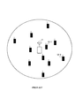
図1に、従来の無線通信システムの構成を模式的に示す。図1に示す無線通信システムは、基地局装置11と複数の通信端末装置12とを含んで構成される。また、複数の通信端末装置12について、基地局装置11の近くに位置し受信状態の良いものを通信端末装置12−1とする。また、基地局装置11による通信エリアの境界、即ち、セルエッジ付近に位置するものを通信端末装置12−2とする。 FIG. 1 schematically shows a configuration of a conventional wireless communication system. The wireless communication system shown in FIG. 1 includes a base station device 11 and a plurality of communication terminal devices 12. Moreover, about the some communication terminal device 12, the thing located near the base station apparatus 11 and a good reception state is set as the communication terminal device 12-1. Further, a communication terminal device 12-2 is located at the boundary of the communication area by the base station device 11, that is, located near the cell edge.
図2に、通信端末装置12が無線通信を開始するに際して、通信端末装置12と基地局装置11との間で送受信される無線信号を時系列で示す。図2に示すように、先ず、基地局装置11が下り回線における共通パイロットチャネル(CPICH:Common Pilot Channel)を用いて複数の通信端末装置12に向けて一定の電力でパイロット信号を送信する。 FIG. 2 shows, in a time series, radio signals transmitted and received between the communication terminal apparatus 12 and the base station apparatus 11 when the communication terminal apparatus 12 starts radio communication. As shown in FIG. 2, first, the base station apparatus 11 transmits a pilot signal with a constant power to a plurality of communication terminal apparatuses 12 using a common pilot channel (CPICH) in the downlink.
次いで、通信端末装置12は、このパイロット信号を受信したときに、その受信品質(図2ではCPICHにおけるパイロット信号の受信電力)に対応付けられた送信電力で上り回線におけるランダムアクセスチャネル(RACH:Random Access Channel)を用いて基地局装置11に対してアクセス要求信号を送信する。このRACHのサブチャネルとして使用できるリソース、例えば、タイミング、拡散コード及びサブキャリア等は予め決められており、通信端末装置12は、アクセス要求信号の送信に際して、その決められたリソースの中から1つをランダムに選択するようになっている。 Next, when the communication terminal apparatus 12 receives this pilot signal, the communication terminal apparatus 12 uses a random access channel (RACH: Random) in the uplink with transmission power associated with the reception quality (reception power of the pilot signal in CPICH in FIG. 2). An access request signal is transmitted to the base station apparatus 11 using (Access Channel). Resources that can be used as sub-channels of this RACH, for example, timing, spreading code, subcarrier, etc. are determined in advance, and the communication terminal apparatus 12 selects one of the determined resources when transmitting the access request signal. Is selected at random.
続いて、基地局装置11は、このアクセス要求信号を受信したときに、フォワードアクセスチャネル(FACH:Forward Access Channel)を用いて通信端末装置12に向けて一定の電力でアクセス許可信号を送信する。続いて、通信端末装置12は、このアクセス許可信号を受信したときに、上り回線におけるデータチャネルを用いて基地局装置11に対して前記パイロット信号の受信品質に対応付けられた送信電力でデータパケットを送信する。なお、図2において、各チャネルにおける下向きの矢印は下り回線であることを、上向きの矢印は上り回線であることをそれぞれ示す。 Subsequently, when the base station apparatus 11 receives this access request signal, the base station apparatus 11 transmits an access permission signal to the communication terminal apparatus 12 with constant power using a forward access channel (FACH). Subsequently, when the communication terminal apparatus 12 receives the access permission signal, the communication terminal apparatus 12 transmits a data packet with transmission power associated with the reception quality of the pilot signal to the base station apparatus 11 using the data channel in the uplink. Send. In FIG. 2, a downward arrow in each channel indicates a downlink, and an upward arrow indicates an uplink.
また、このような従来の技術の他に、通信端末装置12が、先ず基地局装置11に対して送信電力を徐々に上げながら、プリアンブルと呼ばれる短いパケットを送信し、基地局装置11がこのプリアンブルを検出したときに、通信端末装置12が基地局装置11に対してアクセス要求信号を送信する技術も開発されている(例えば、特許文献1参照)。 In addition to such a conventional technique, the communication terminal apparatus 12 first transmits a short packet called a preamble while gradually increasing the transmission power to the base station apparatus 11, and the base station apparatus 11 transmits the preamble. A technique has also been developed in which the communication terminal apparatus 12 transmits an access request signal to the base station apparatus 11 when the communication terminal apparatus 12 is detected (see, for example, Patent Document 1).
しかしながら、図2に示すような従来の技術では、複数の通信端末装置12がそれぞれ、CPICHにおけるパイロット信号を同時に受信し、アクセス要求信号を送信するRACHのサブチャネルをランダムに選択するため、複数の通信端末装置12が同一のサブチャネルでアクセス要求信号を送信して、基地局装置11がそれらのアクセス要求信号を受信できなくなるおそれがある。 However, in the conventional technique as shown in FIG. 2, each of the plurality of communication terminal apparatuses 12 simultaneously receives a pilot signal in CPICH and randomly selects a RACH subchannel for transmitting an access request signal. There is a possibility that the communication terminal apparatus 12 transmits access request signals on the same subchannel, and the base station apparatus 11 cannot receive those access request signals.
基地局装置11が通信端末装置12からのアクセス要求信号を受信できない場合には、基地局装置11から通信端末装置12にアクセス許可信号が送信されないため、通信端末装置12は、アクセス要求信号の送信から所定時間経過した後に、先に送信したアクセス要求信号が基地局装置11に受信されなかったと判定して、所定のバックオフ時間の経過時に、基地局装置11に対して再度アクセス要求信号を送信する。つまり、このような従来の技術では、複数の通信端末装置12からRACHを用いて送信されるアクセス要求信号がコリジョンによって基地局装置に受信されなくなるおそれがあり、また通信端末装置12が先に送信したアクセス要求信号が基地局装置11に受信されたか判定するまでに時間を要し、さらに通信端末装置12がアクセス要求信号を再送信するまでに所定のバックオフ時間が設定されることから、通信端末装置12が無線通信を開始するまでに要する時間が長期化して、無線通信システムにおけるスループットが低下する問題がある。 When the base station apparatus 11 cannot receive the access request signal from the communication terminal apparatus 12, the access permission signal is not transmitted from the base station apparatus 11 to the communication terminal apparatus 12, and therefore the communication terminal apparatus 12 transmits the access request signal. After the elapse of a predetermined time, it is determined that the previously transmitted access request signal has not been received by the base station apparatus 11, and the access request signal is transmitted again to the base station apparatus 11 when the predetermined back-off time has elapsed. To do. That is, in such a conventional technique, there is a possibility that an access request signal transmitted from a plurality of communication terminal apparatuses 12 using the RACH may not be received by the base station apparatus due to collision, and the communication terminal apparatus 12 transmits first. Since it takes time to determine whether the access request signal received by the base station apparatus 11 and the communication terminal apparatus 12 retransmits the access request signal, a predetermined back-off time is set. There is a problem in that the time required for the terminal device 12 to start wireless communication is prolonged and throughput in the wireless communication system is reduced.
また、このような従来の技術では、セルエッジ付近に位置する通信端末装置12−2からアクセス要求信号が大電力で複数回送信されることになるため、そのアクセス要求信号が隣接する他セルにおいて干渉信号となる問題がある。 Moreover, in such a conventional technique, since the access request signal is transmitted a plurality of times with high power from the communication terminal apparatus 12-2 located near the cell edge, the access request signal interferes with other adjacent cells. There is a problem that becomes a signal.
さらに、このような従来の技術では、基地局装置11がアクセス要求信号を受信したときに、そのアクセス要求信号を送信した通信端末装置12の位置を確認できないため、基地局装置11は、自セル内に位置する全ての通信端末装置12がアクセス許可信号を受信できるように、FACHを用いて送信されるアクセス許可信号を送信電力制御することなく大電力で送信することから、上記同様にアクセス許可信号が隣接する他セルにおいて干渉信号となる問題がある。 Further, in such a conventional technique, when the base station apparatus 11 receives the access request signal, the base station apparatus 11 cannot confirm the position of the communication terminal apparatus 12 that transmitted the access request signal. Since all the communication terminal devices 12 located within are able to receive the access permission signal, the access permission signal transmitted using the FACH is transmitted with high power without controlling the transmission power. There is a problem that the signal becomes an interference signal in another adjacent cell.
また、特許文献1に記載された技術では、通信端末装置12が基地局装置11に対してプリアンブルを用いて求めた必要十分な電力でアクセス要求信号を送信することになるため、セルエッジ付近に位置する通信端末装置12−2から送信されるアクセス要求信号が隣接する他セルにおいて干渉信号となる問題は改善できるものの、上記アクセス要求信号のコリジョンの発生に由来するスループット低下の問題、並びに基地局装置11の送信するアクセス許可信号が隣接する他セルにおいて干渉信号となる問題については、何ら改善されない。
Moreover, in the technique described in
本発明の目的は、自セル内の複数の通信端末装置から同時にアクセス要求信号が送信されても、それらのコリジョンを回避して、自セルに隣接する他セルにおける干渉信号の発生を防止し、かつ、自セルにおけるスループットを改善し、アクセス許可信号の送信電力を制御して自セルに隣接する他セルにおける干渉信号の発生を防止する基地局装置及び通信方法を提供することである。 The object of the present invention is to prevent the occurrence of interference signals in other cells adjacent to the own cell, avoiding those collisions even when access request signals are transmitted simultaneously from a plurality of communication terminal devices in the own cell, Another object of the present invention is to provide a base station apparatus and a communication method that improve the throughput in the own cell and control the transmission power of the access permission signal to prevent the generation of an interference signal in another cell adjacent to the own cell.
本発明に係る基地局装置は、通信端末装置と無線通信を行う基地局装置であって、前記通信端末装置に、パイロット信号を送信する送信部と、それぞれが、前記通信端末装置で測定される前記パイロット信号の異なる受信電力の範囲に関連付けられた複数のグループであって、それぞれ、前記通信端末装置が前記基地局装置との通信を開始する際の競合チャネルを用いた初期アクセスのために用いられる複数のコードを含む前記複数のグループの内、前記通信端末装置において、前記パイロット信号の前記受信電力に基づいて選択された前記グループの前記複数のコードの中から、ランダムに選択されたコードを使用して前記初期アクセスのために送信された信号を、受信する受信部と、を有し、ランダムに選択された前記コードは、前記基地局装置に対して前記受信電力の範囲を示し、低い前記受信電力の範囲は、高い前記受信電力の範囲よりも狭く、低い前記受信電力の範囲に関連付けられたグループに含まれる前記複数のコードの数は、高い前記受信電力の範囲に関連付けられたグループに含まれる前記複数のコードの数よりも多い構成を採る。 The base station apparatus according to the present invention is a base station apparatus that performs radio communication with a communication terminal apparatus, and each of the transmitter that transmits a pilot signal to the communication terminal apparatus is measured by the communication terminal apparatus. A plurality of groups associated with different received power ranges of the pilot signal, each used for initial access using a contention channel when the communication terminal apparatus starts communication with the base station apparatus among the plurality of groups including a plurality of code to be, in the communication terminal apparatus, from among the plurality of code of the group to which the selected on the basis of the received power of the pilot signals, randomly selected code the code of the signal transmitted for the initial access using, have a, a receiver for receiving, randomly selected to, the group The range of the received power is indicated to a station apparatus, and the range of the low received power is narrower than the range of the high received power, and the plurality of codes included in the group associated with the low received power range The number is configured to be larger than the number of the plurality of codes included in the group associated with the high reception power range .
本発明によれば、自セル内の複数の通信端末装置から同時にアクセス要求信号が送信されても、それらのコリジョンを回避して、自セルに隣接する他セルにおける干渉信号の発生を防止し、かつ、自セルにおけるスループットを改善することができ、また、アクセス許可信号の送信電力を制御して自セルに隣接する他セルにおける干渉信号の発生を防止することができる。 According to the present invention, even when access request signals are transmitted simultaneously from a plurality of communication terminal devices in the own cell, avoiding those collisions, preventing the occurrence of interference signals in other cells adjacent to the own cell, In addition, the throughput in the own cell can be improved, and the transmission power of the access permission signal can be controlled to prevent the generation of interference signals in other cells adjacent to the own cell.
以下、本発明の実施の形態について、適宜図面を参照しながら詳細に説明する。ただし、実施の形態において、同一機能を有する構成には同一符号を付し、重複する説明は省略する。 Hereinafter, embodiments of the present invention will be described in detail with reference to the drawings as appropriate. However, in the embodiment, configurations having the same functions are denoted by the same reference numerals, and redundant description is omitted.
(実施の形態1)
図3に、本発明の実施の形態1に係る無線通信システムの構成を模式的に示す。本実施の形態に係る無線通信システムは、複数の通信端末装置200及び基地局装置300を含んで構成される。この無線通信システムでは、複数の通信端末装置200が、基地局装置300から、例えばCPICHで、送信されるパイロット信号の受信品質を基準にして3つの等級に区分される。以下、この受信品質の良い方から順に、グループ1、グループ2及びグループ3と称する。また、グループ1に属するものを通信端末装置200−1と、グループ2に属するものを通信端末装置200−2と、グループ3に属するものを通信端末装置200−3と、表記する。従って、この無線通信システムにおけるセルエッジ付近に存在する通信端末装置200は、グループ3に属することになる。
(Embodiment 1)
FIG. 3 schematically shows the configuration of the radio communication system according to
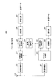
図4は、本発明の実施の形態1に係る通信端末装置200の構成を示すブロック図である。通信端末装置200は、受信無線部201、チャネル分離部202、復調部203、復号部204、受信品質測定部205、使用サブチャネル選択部206、符号化部207、変調部208、サブチャネル割当部209、送信電力制御部211、送信無線部212及びアンテナ素子213を具備する。
FIG. 4 is a block diagram showing a configuration of
受信無線部201は、後述する基地局装置300からCPICHで送信されたパイロット信号及びFACHで送信されたアクセス許可信号等をアンテナ素子213を介して受信し、それらの受信信号に周波数変換及びアナログ/ディジタル変換等の所定の受信処理を施し、受信処理後の受信信号をチャネル分離部202に入力する。
The
チャネル分離部202は、受信無線部201から入力された受信信号について使用されたチャネルを判別し、判別したチャネルがCPICHであれば、その受信信号、即ち、パイロット信号を受信品質測定部205に入力する。一方で、CPICH以外、即ち、FACH等であれば、その受信信号を復調部203に入力する。
The
復調部203は、チャネル分離部202から入力された受信信号を所定の方式で復調し、復調後の受信信号を復号部204に入力する。
復号部204は、復調部203から入力された受信信号を所定の方式で復号して受信データを生成し、生成した受信データを図示しない制御部等に入力する。
The
受信品質測定部205は、チャネル分離部202から入力されたパイロット信号の受信品質、例えば、信号電力対干渉電力比(SIR:Signal-to-Interference power Ratio)や受信電力レベルを測定し、その測定結果を使用サブチャネル選択部206及び送信電力制御部211にそれぞれ通知する。
The reception
使用サブチャネル選択部206は、等級化されたパイロット信号の受信品質とその各等級に割り当てられたサブチャネルとの「対応表」を備えている。そして、この対応表に基づいて、受信品質測定部205から通知されたパイロット信号の受信品質の測定結果に対応付けられたRACHのサブチャネル群を選定し、選定されたサブチャネル群の中からアクセス要求信号の送信に使用するサブチャネルを1つランダムに選択する。使用サブチャネル選択部206は、選択したサブチャネルをサブチャネル割当部209に通知する。なお、この等級化されたパイロット信号の受信品質とその各等級に割り当てられたRACHのサブチャネルとを示す対応表については、後述する。
The used
符号化部207は、図示しない制御部等から入力された送信データを所定の方式で符号化して送信信号を生成し、生成した送信信号を変調部208に入力する。
変調部208は、符号化部207から入力された送信信号を所定の方式で変調し、変調後の送信信号をサブチャネル割当部209に入力する。
サブチャネル割当部209は、無線通信の開始に際し、図示しない制御部等から入力されたアクセス要求信号に対して、使用サブチャネル選択部206から通知されたRACHのサブチャネルで送信するために所定のリソースを割り当てる。この所定のリソースとしては、タイミング、拡散コード又はマルチキャリア信号におけるサブキャリア等が例示される。そして、サブチャネル割当部209は、所定のリソースを割り当てたアクセス要求信号を所定のタイミングで送信電力制御部211に入力する。また、サブチャネル割当部209は、アクセス要求信号を送信電力制御部211に入力してから所定時間内に、基地局装置300からアクセス許可信号が送信されてこないときには、所定のバックオフ時間の経過時に、再びアクセス要求信号に対して使用サブチャネル選択部206から通知されたRACHのサブチャネルを割り当て、割り当てたアクセス要求信号を送信電力制御部211に入力する。一方で、サブチャネル割当部209は、アクセス要求信号を送信電力制御部211に入力してから所定時間内に、基地局装置300からアクセス許可信号が送信されてきたときには、そのアクセス許可信号によって指定されたデータチャネルで変調部208から入力された送信信号を送信するため、その送信信号に所定のリソースを割り当てて、所定のタイミングで送信電力制御部211にその送信信号を入力する。
At the start of wireless communication, the
送信電力制御部211は、サブチャネル割当部209から入力されたアクセス要求信号又は送信信号を、受信品質測定部205から通知されたパイロット信号の受信品質の測定結果に対応付けられた電力となるように増幅し、増幅後のアクセス要求信号又は送信信号を送信無線部212に入力する。
The transmission
送信無線部212は、送信電力制御部211から入力されたアクセス要求信号又は送信信号に対して、ディジタル/アナログ変換や周波数変換等の所定の送信処理を施した後に、アンテナ素子213を介して基地局装置300に無線送信する。
The
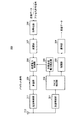
図5は、本発明の実施の形態1に係る基地局装置300の構成を示すブロック図である。基地局装置300は、受信無線部301、RACH検出部302、復調部303、復号部304、所要送信電力算出部305、符号化部306、変調部307、送信電力制御部308、多重部309、送信無線部311及びアンテナ素子312を具備する。
FIG. 5 is a block diagram showing a configuration of
受信無線部301は、通信端末装置200からRACHで送信されたアクセス要求信号及びデータチャネルで送信された送信信号をアンテナ素子312を介して受信し、それらの受信信号に周波数変換やアナログ/ディジタル変換等の所定の受信処理を施し、受信処理後の受信信号をRACH検出部302に入力する。
The
RACH検出部302は、受信無線部301から入力された受信信号についてアクセス要求信号を検出し、アクセス要求信号が検出されたときには、そのアクセス要求信号を所要送信電力算出部305に入力し、一方でアクセス要求信号が検出されないときには、受信信号に通常のデータ信号のみが含まれると判断して、その受信信号を復調部303に入力する。
The
復調部303は、RACH検出部302から入力された受信信号に所定の方式で復調処理を施し、復調後の受信信号を復号部304に入力する。
復号部304は、復調部303から入力された受信信号を所定の方式で復号して受信データを生成し、生成した受信データを図示しない制御部等に入力する。
The
所要送信電力算出部305は、RACH検出部302から入力されたアクセス要求信号について、その送信に使用されたRACHのサブチャネルを判定する。所要送信電力算出部305は、使用サブチャネル選択部206が備える対応表を有しており、この対応表に基づいて、判定されたRACHのサブチャネルから通信端末装置200におけるパイロット信号の受信品質を把握する。また、所要送信電力算出部305は、判定されたサブチャネルとアクセス許可信号の送信電力とを対応付けた「換算表」も有しており、この換算表を用いて、判定されたRACHのサブチャネルに対応付けられた送信電力を算出し、算出した送信電力を送信電力制御部308に通知する。なお、この換算表については、後述する。
The required transmission
符号化部306は、図示しない制御部等から入力されたアクセス許可信号又は送信データに対して、所定の方式で符号化処理を施して送信信号を生成し、生成した送信信号を変調部307に入力する。
The
変調部307は、符号化部306から入力された送信信号を所定の方式で変調し、変調後の送信信号を送信電力制御部308に入力する。
送信電力制御部308は、変調部307から入力された送信信号を、所要送信電力算出部305から通知された電力に増幅し、増幅後の送信信号を多重部309に入力する。
Transmission
多重部309は、図示しない制御部等からパイロット信号を定期的に入力され、このパイロット信号が入力されるタイミングにおいて、送信電力制御部308から入力された送信信号にこのパイロット信号を多重し、多重後の送信信号を送信無線部311に入力する。なお、多重部309は、パイロット信号が入力されないタイミングでは、送信電力制御部308から入力された送信信号をそのまま送信無線部311に通過させる。
The
送信無線部311は、多重部309から入力された送信信号に対して、ディジタル/アナログ変換や周波数変換等の送信処理を施し、送信処理後の送信信号をアンテナ素子312を介して通信端末装置200に無線送信する。
The
次いで、通信端末装置200及び基地局装置300の動作について、図6〜図13を用いて具体的に説明する。
Next, operations of
図6に、通信端末装置200がRACHのサブチャネルのリソースとして拡散コードを使用する場合において、パイロット信号の受信品質を基準として等級化されたグループ1、グループ2又はグループ3に対する拡散コードの割り当て態様を示す。図6では、パイロット信号の受信品質が最も良いグループ1には2つの拡散コード#1、#2が割り当てられ、その受信品質が中位のグループ2には3つの拡散コード#3、#4、#5が割り当てられ、その受信品質が最も悪いグループ3には使用可能な残り全ての拡散コード#6〜#n(nは10以上の自然数)が割り当てられている。
FIG. 6 shows how spreading codes are assigned to
また、図7に、通信端末装置200がRACHのサブチャネルのリソースとしてマルチキャリア信号におけるサブキャリアを使用する場合において、パイロット信号の受信品質を基準として等級化されたグループ1、グループ2又はグループ3に対するサブキャリアの割り当て態様を示す。図7では、パイロット信号の受信品質が最も良いグループ1には2つのサブキャリア#1、#2が割り当てられ、その受信品質が中位のグループ2には3つのサブキャリア#3、#4、#5が割り当てられ、その受信品質が最も悪いグループ3には使用可能な残り全てのサブキャリア#6〜#n(nは10以上の自然数)が割り当てられている。
FIG. 7
また、図8に、通信端末装置200がRACHのサブチャネルのリソースとしてOFDM(Orthogonal Frequency Division Multiplexing)信号のシンボルを使用する場合において、パイロット信号の受信品質を基準として等級化されたグループ1、グループ2又はグループ3に対するOFDM信号のシンボルの割り当て態様を示す。図8では、パイロット信号の受信品質が最も良いグループ1には最初の2つのOFDM信号のシンボルが割り当てられ、その受信品質が中位のグループ2には続く3つのOFDM信号のシンボルが割り当てられ、その受信品質が最も悪いグループ3には使用可能な残り全てのOFDM信号のシンボルが割り当てられている。なお、RACHのサブチャネルのリソースを通信方式で規格されたタイムスロットとしても、OFDM信号のシンボルと同様に割り当てることができる。
FIG. 8
図9に、使用サブチャネル選択部206が備える対応表の一例を示す。この対応表では、受信品質測定部205によるパイロット信号の受信品質としての受信SIRの測定結果が15dB以上の場合をグループ1とし、5〜15dBの場合をグループ2とし、−3〜5dBの場合をグループ3としている。図9に示すグループ1、グループ2及びグループ3にはそれぞれ、図6〜図8に示すような態様でRACHのサブチャネルが割り当てられている。従って、使用サブチャネル選択部206は、この対応表に基づいて、受信品質測定部205から通知されたパイロット信号の受信品質の測定結果に対応して図6〜図8に示すような態様で割り当てられたRACHのサブチャネルを選定し、選定された複数のサブチャネルの中からアクセス要求信号の送信に使用するサブチャネルを1つランダムに選択する、ことになる。なお、図9に示す対応表では、受信品質測定部205によるパイロット信号の受信品質の測定結果が−3dB未満の場合がいずれのグループにも対応付けされていない。これは、パイロット信号の受信品質の測定結果が−3dB未満であれば伝搬路状況が劣悪に過ぎるため、通信端末装置200がアクセス要求信号を送信しても基地局装置300に受信されないおそれが高いことから、隣接する他セルにおける干渉信号の発生を防止するため、通信端末装置200が不必要なアクセス要求信号の送信を行わないようにするものである。なお、この場合、通信端末装置200は、伝搬路上におけるフェージング又はシャドウイング等による減衰が回復して、パイロット信号の受信品質の測定結果が−3dB以上になれば、基地局装置300にアクセスすることができる。
FIG. 9 shows an example of a correspondence table provided in the used
また、図10に、所要送信電力算出部305が有する換算表の一例を示す。この換算表は図9に示す対応表と相関があり、通信端末装置200におけるアクセス許可信号の所要受信SIRが0dBと仮定して、基地局装置300におけるアクセス許可信号の送信電力がパイロット信号の送信電力を基準としてデシベルで表現されている。具体的には、グループ1については、通信端末装置200−1におけるパイロット信号の受信品質の測定結果が15dB以上であることから、通信端末装置200−1におけるアクセス許可信号の受信品質が0dB以上となるように、基地局装置300におけるアクセス許可信号の送信電力はパイロット信号の送信電力を基準として−15dBに設定される。同様に、グループ2については、通信端末装置200−2におけるパイロット信号の受信品質の測定結果が5dB以上であることから、基地局装置300におけるアクセス許可信号の送信電力はパイロット信号の送信電力を基準として−5dBに設定される。同様に、グループ3については、通信端末装置200−3におけるパイロット信号の受信品質の測定結果が−3dB以上であることから、基地局装置300におけるアクセス許可信号の送信電力はパイロット信号の送信電力を基準として3dBに設定される。
FIG. 10 shows an example of a conversion table that the required transmission
図11に、グループ1に属する通信端末装置200−1が通信開始に際して基地局装置300との間で送受信する無線信号を時系列で示す。同様に、図12にグループ2に属する通信端末装置200−2が通信開始に際して基地局装置300との間で送受信する無線信号を、また図13にグループ3に属する通信端末装置200−3が通信開始に際して基地局装置300との間で送受信する無線信号を、時系列で示す。なお、図11〜図13では、パイロット信号の受信品質としてその受信電力レベルを使用する。図11〜図13に示すように、通信端末装置200−1〜200−3はいずれも、パイロット信号の受信品質の測定結果を基準として、RACHで送信するアクセス要求信号及びデータチャネルで送信するデータパケットの送信電力制御を行う。一方で、基地局装置300は、通信端末装置200の使用したRACHのサブチャネルを判定することにより、通信端末装置200におけるパイロット信号の受信品質の測定結果を間接的に把握して、換言すればその通信端末装置200がグループ1〜3のいずれに属するか把握して、FACHで送信するアクセス許可信号の送信電力制御を行うことになる。従って、図11〜図13を比較すれば、アクセス許可信号を送信するFACHの送信電力がそれぞれ異なっており、かつ、パイロット信号の受信品質が最も低い通信端末装置200−3を示す図13のFACHの送信電力が最も高くなっていることが判る。
FIG. 11 shows, in time series, radio signals transmitted / received to / from
このように、本実施の形態に係る無線通信システムによれば、通信端末装置200がパイロット信号の受信品質の測定結果を等級化して、その各等級に専用のRACHのサブチャネルを予め割り当てておき、実際の測定結果に応じて、アクセス要求信号の送信に使用するRACHのサブチャネルを選択するため、複数の通信端末装置200が同一のRACHのサブチャネルを同時に使用する確率を低下させることができる。その結果、本実施の形態に係る無線通信システムによれば、アクセス要求信号が基地局装置300に確実に受信されるようになり、アクセス要求信号の再送信回数が減るため、通信端末装置200が無線通信を短期間で開始でき、かつ、自セルにおけるスループットが改善し、かつ、自セルに隣接する他セルにおける干渉信号の発生を抑制することができる。
As described above, according to the radio communication system according to the present embodiment,
また、本実施の形態に係る無線通信システムによれば、基地局装置300が、通信端末装置200−1〜200−3それぞれにおけるアクセス要求信号の受信品質に応じて必要十分な送信電力でアクセス許可信号を送信するため、自セルに隣接する他セルにおいてアクセス許可信号が干渉信号となることを抑制することができる。
Also, according to the radio communication system according to the present embodiment,
また、本実施の形態に係る無線通信システムによれば、通信端末装置200における使用サブチャネル選択部206の備える対応表において、等級化されたパイロット信号の受信品質の上位等級(例えばグループ1)よりも下位等級(例えばグループ3)に多くのサブチャネルが割り当てられているため、セルエッジ付近に位置する通信端末装置200ほど同一のRACHのサブチャネルを同時に使用する確率が低下してアクセス要求信号の再送信回数が減ることから、自セルに隣接する他セルにおける干渉信号の発生を効果的に防止することができる。
Also, according to the radio communication system according to the present embodiment, in the correspondence table provided in use
また、本実施の形態に係る無線通信システムでは、通信端末装置200における使用サブチャネル選択部206の備える対応表において、等級化されたパイロット信号の受信品質に関し、上位等級よりも下位等級の受信品質の範囲の方が狭くなっている。具体的には、グループ1の受信品質の範囲は15dB以上と上限がなく、グループ2の受信品質の範囲は5〜15dBの10dBとなっており、グループ3の受信品質の範囲は−3〜5dBの8dBとなっている。従って、本実施の形態に係る無線通信システムによれば、パイロット信号の受信品質の範囲が狭い下位等級ほどより多くのサブチャネルが割り当てられていることになるため、セルエッジ付近に位置する通信端末装置200のアクセス要求信号の再送信回数を一層効果的に減らせることから、自セルに隣接する他セルにおける干渉信号の発生をより効果的に防止することができる。
Also, in the wireless communication system according to the present embodiment, the reception quality of the graded pilot signal in the correspondence table included in the used
なお、本実施の形態について、以下のように変形したり、応用したりしてもよい。 The present embodiment may be modified or applied as follows.
本実施の形態に係る基地局装置300では、所要送信電力算出部305がアクセス要求信号の送信に使用されたRACHのサブチャネルを判定し、判定されたサブチャネルに対応付けられた送信電力を送信電力制御部308に通知する場合について説明したが、本発明はこの場合に限定されるものではなく、例えば、所要送信電力算出部305がアクセス要求信号の受信品質を測定する要求信号測定部を具備し、この要求信号測定部によって測定された受信品質と通信端末装置200における所要受信品質、即ち、送信電力制御における目標受信品質とを比較して、それらの受信品質の差が所定値よりも大きければ、RACHのサブチャネルに対応付けられた送信電力を増減し、増減後の送信電力を送信電力制御部308に通知するようにしてもよい。
In
この所要送信電力算出部305におけるアクセス許可信号の送信電力の算出は、アクセス要求信号の受信品質に基づくクローズドループによる算出であるため、通信端末装置200においてパイロット信号の受信からアクセス要求信号の送信までに時間を要する場合、或いは伝搬路状況の変化が速い場合等には、クローズドループによる送信電力の算出では、算出された送信電力に実際の伝搬路状況が的確に反映されていないおそれがある。そこで、所要送信電力算出部305において、クローズドループによる送信電力の算出に加えて、アクセス要求信号の受信品質を測定するオープンループによる送信電力の算出を行えば、アクセス許可信号の送信電力制御を一層正確に行うことができるようになる。
Since the calculation of the transmission power of the access permission signal in the required transmission
(実施の形態2)
本発明の実施の形態2では、基地局装置がRACHの使用リソースに基づいてFACHに対して符号化率及び変調方式を適応的に変化させる場合について説明する。なお、本実施の形態に係る通信端末装置の構成は、図4と同じなので、図4を援用して説明する。
(Embodiment 2)
In
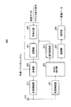
図14は、本発明の実施の形態2に係る基地局装置400の構成を示すブロック図である。基地局装置400は、受信無線部301、RACH検出部302、復調部303、復号部304、適応制御部413、符号化部406、変調部407、多重部309、送信無線部311及びアンテナ素子312を具備する。
FIG. 14 is a block diagram showing a configuration of
適応制御部413は、RACH検出部302から入力されたアクセス要求信号について、その送信に使用されたRACHのサブチャネルを判定し、判定されたサブチャネルとアクセス許可信号の送信パラメータ、即ち、変調方式と符号化率のセットとを対応付けた換算表を用いて、変調方式及び符号化率を設定し、設定した変調方式及び符号化率を符号化部406及び変調部407に入力する。
The
符号化部406は、図示しない制御部等から入力されたアクセス許可信号又は送信データに対して、適応制御部413から入力された送信パラメータ(符号化率及び変調方式の情報)に従った符号化率又は符号化方法で符号化処理を施して送信信号を生成し、生成した送信信号を変調部407に入力する。
The
変調部407は、符号化部406から入力された送信信号を適応制御部413から入力された送信パラメータに従った変調方式で変調し、変調後の送信信号を多重部309に入力する。
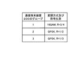
図15に、適応制御部413が有する換算表の一例を示す。この換算表は図9に示す対応表と相関があり、通信端末装置200における受信品質が高いほど、高い変調レベル及び符号化率となっている。例えば、グループ1では受信品質が15dB以上であるため、所要SIRが15dBである送信パラメータ、つまり受信SIRが15dB以上であれば十分低い誤り率で受信できる最も伝送効率の高い送信パラメータである16QAM、R=3/4を用い、グループ2では、受信SIRが5dB〜15dBであるため、所要SIRが5dBである送信パラメータのQPSK、R=1/2を用いる。グループ3についても同様である。
In FIG. 15, an example of the conversion table which the
伝送効率の高い送信パラメータであるほど、基地局装置400はアクセス許可信号の送信を短時間で終わらせることができる。
The
このように本実施の形態によれば、基地局装置400が、通信端末装置200−1〜200−3それぞれにおけるアクセス要求信号の受信品質に応じて十分に低い誤り率で受信できる最も伝送効率の高い送信パラメータを用いてアクセス許可信号を送信するため、アクセス許可信号の送信時間を短縮することができ、他セルにおいてアクセス許可信号が干渉信号となることを抑制することができる。
Thus, according to the present embodiment,
上記各実施の形態では、本発明をハードウェアで構成する場合を例にとって説明したが、本発明はソフトウェアで実現することも可能である。 Although cases have been described with the above embodiment as examples where the present invention is configured by hardware, the present invention can also be realized by software.
また、上記各実施の形態の説明に用いた各機能ブロックは、典型的には集積回路であるLSIとして実現される。これらは個別に1チップ化されてもよいし、一部または全てを含むように1チップ化されてもよい。ここでは、LSIとしたが、集積度の違いにより、IC、システムLSI、スーパーLSI、ウルトラLSIと呼称されることもある。 Each functional block used in the description of each of the above embodiments is typically realized as an LSI which is an integrated circuit. These may be individually made into one chip, or may be made into one chip so as to include a part or all of them. The name used here is LSI, but it may also be called IC, system LSI, super LSI, or ultra LSI depending on the degree of integration.
また、集積回路化の手法はLSIに限るものではなく、専用回路または汎用プロセッサで実現してもよい。LSI製造後に、プログラムすることが可能なFPGA(Field Programmable Gate Array)や、LSI内部の回路セルの接続や設定を再構成可能なリコンフィギュラブル・プロセッサーを利用してもよい。 Further, the method of circuit integration is not limited to LSI's, and implementation using dedicated circuitry or general purpose processors is also possible. An FPGA (Field Programmable Gate Array) that can be programmed after manufacturing the LSI, or a reconfigurable processor that can reconfigure the connection and setting of circuit cells inside the LSI may be used.
さらには、半導体技術の進歩または派生する別技術によりLSIに置き換わる集積回路化の技術が登場すれば、当然、その技術を用いて機能ブロックの集積化を行ってもよい。バイオ技術の適応等が可能性としてありえる。 Furthermore, if integrated circuit technology comes out to replace LSI's as a result of the advancement of semiconductor technology or a derivative other technology, it is naturally also possible to carry out function block integration using this technology. Biotechnology can be applied.
なお、上記各実施の形態に係る無線通信システムでは、パイロット信号の受信品質の等級に対応させて複数の通信端末装置200を3つのグループに区分する場合について説明したが、本発明はこの場合に限定されるものではなく、例えば、さらにグループの数を増やしてもよい。
In the radio communication system according to each of the above-described embodiments, a case has been described in which a plurality of
また、アクセス許可信号は、例えば3GPP規格では、AICH(Acknowledge Indicator Channel)、FACH(Forward Access Channel)、S−CCPCH(Secondary-Common Control Physical Channel)、HS−SCCH(High Speed-Shared Control Channel)、DPCH(Dedicated Physical Channel)を用いて送信してもよい。 In addition, for example, in the 3GPP standard, the access permission signal is AICH (Acknowledge Indicator Channel), FACH (Forward Access Channel), S-CCPCH (Secondary-Common Control Physical Channel), HS-SCCH (High Speed-Shared Control Channel), You may transmit using DPCH (Dedicated Physical Channel).
また、上記各実施の形態においては、RACHによるアクセス要求、FACHによるアクセス許可を行い、その後データパケットを送信するものとして説明したが、RACHをアクセス要求信号、FACHをアクセス許可信号以外のデータの送信に用いても同様の効果を得ることができる。例えば、短いパケットや遅延要求の厳しいパケット等では、上り回線のデータパケットをRACHで、下り回線のデータパケットをFACHで送信するようにしてもよい。 In each of the above-described embodiments, it has been described that an access request by RACH and access permission by FACH are performed and then a data packet is transmitted. However, RACH is transmitted as an access request signal, and FACH is transmitted as data other than an access permission signal. The same effect can be obtained even if it is used. For example, for short packets or packets with severe delay requirements, uplink data packets may be transmitted by RACH and downlink data packets by FACH.
また、上記各実施の形態におけるRACHは、あらかじめユーザ個別のリソースが割り当てられない競合チャネルであればその他のものでもよい。 In addition, the RACH in each of the above embodiments may be other as long as it is a contention channel to which a user-specific resource is not allocated in advance.
また、上記の実施の形態において、受信品質は受信SIRから推定するものとして説明したが、受信SNR、受信CIR、受信SINR、受信CINR、受信電力、干渉電力、ビット誤り率、スループット、所定の誤り率を達成できるMCS(変調方式と符号化率の組み合わせ)、などにより推定してもよい。また、基地局装置はNode B、通信端末装置はUEと表現されることもある。 In the above embodiment, the reception quality is estimated from the reception SIR. However, the reception SNR, reception CIR, reception SINR, reception CINR, reception power, interference power, bit error rate, throughput, and predetermined error are described. It may be estimated by MCS (combination of modulation scheme and coding rate) that can achieve the rate. Further, the base station apparatus may be expressed as Node B, and the communication terminal apparatus may be expressed as UE.
本発明の第1の態様は、基地局装置と無線通信を行う通信端末装置であって、前記基地局装置から送信されたパイロット信号を受信する受信手段と、受信された前記パイロット信号の受信品質を測定する測定手段と、前記パイロット信号の受信品質の測定結果に応じて、前記基地局装置への信号の送信に使用するサブチャネルを選択する選択手段と、選択されたサブチャネルを使用して、前記基地局装置に前記信号を送信する送信手段と、を具備する通信端末装置である。 According to a first aspect of the present invention, there is provided a communication terminal apparatus that performs radio communication with a base station apparatus, receiving means for receiving a pilot signal transmitted from the base station apparatus, and reception quality of the received pilot signal Using the selected subchannel, the selecting means for selecting the subchannel used for signal transmission to the base station apparatus according to the measurement result of the reception quality of the pilot signal, And a transmission means for transmitting the signal to the base station apparatus.
本発明の第2の態様は、前記発明において、前記送信手段は、ランダムアクセスチャネルを用いて前記信号を送信する通信端末装置である。 A second aspect of the present invention is the communication terminal apparatus according to the present invention, wherein the transmission means transmits the signal using a random access channel.
本発明の第3の態様は、前記発明において、前記送信手段は、アクセス要求信号を送信する通信端末装置である。 A third aspect of the present invention is the communication terminal apparatus according to the present invention, wherein the transmission means transmits an access request signal.
本発明の第4の態様は、前記選択手段は、等級化された受信品質の上位等級よりも下位等級に多くのサブチャネルを割り当てておき、前記パイロット信号の受信品質の測定結果に対応する等級に割り当てられているサブチャネルの中から前記基地局装置への信号の送信に使用するサブチャネルを選択する通信端末装置である。 According to a fourth aspect of the present invention, the selecting means assigns more subchannels to a lower class than an upper class of graded reception quality, and a class corresponding to a measurement result of the reception quality of the pilot signal. Is a communication terminal device that selects a subchannel to be used for signal transmission to the base station device from among the subchannels assigned to.
本発明の第5の態様は、前記発明において、前記選択手段は、等級化された受信品質について上位等級よりも下位等級の受信品質の範囲を狭くして各等級にサブチャネルを割り当てておき、前記パイロット信号の受信品質の測定結果に対応する等級に割り当てられているサブチャネルの中から前記基地局装置への信号の送信に使用するサブチャネルを選択する通信端末装置である。 According to a fifth aspect of the present invention, in the above invention, the selecting means assigns a subchannel to each grade by narrowing the range of the received quality of the lower grade than the upper grade for the graded received quality, The communication terminal apparatus selects a subchannel to be used for signal transmission to the base station apparatus from among subchannels assigned to a class corresponding to a measurement result of reception quality of the pilot signal.
本発明の第6の態様は、通信端末装置と無線通信を行うものであって、前記通信端末装置から送信された信号を受信する受信手段と、受信された前記信号の送信に使用されたサブチャネルを検出する検出手段と、検出された前記サブチャネルに対応付けられた送信電力、又は検出された前記サブチャネルに対応付けられた変調方式及び符号化率によって、前記通信端末装置に対して信号を送信する送信手段と、を具備する基地局装置である。 According to a sixth aspect of the present invention, there is provided wireless communication with a communication terminal apparatus, a receiving means for receiving a signal transmitted from the communication terminal apparatus, and a sub used for transmitting the received signal. A signal to the communication terminal apparatus is detected by detection means for detecting a channel, transmission power associated with the detected subchannel, or a modulation scheme and a coding rate associated with the detected subchannel. And a transmission means for transmitting the base station apparatus.
本発明の第7の態様は、前記発明において、前記送信手段は、アクセス許可信号を送信する基地局装置である。 A seventh aspect of the present invention is the base station apparatus according to the present invention, wherein the transmission means transmits an access permission signal.
本発明の第8の態様は、前記発明において、前記受信手段によって受信された信号の受信品質を測定する要求信号測定手段を具備し、前記送信手段は、前記要求信号測定手段によって測定された受信品質と送信電力制御における目標受信品質との差に応じて、前記検出手段によって検出された前記サブチャネルに対応付けられた送信電力を増減し、増減された送信電力で前記通信端末装置に対して信号を送信する基地局装置である。 According to an eighth aspect of the present invention, there is provided the request signal measuring means for measuring the reception quality of the signal received by the receiving means in the invention, wherein the transmitting means is the reception signal measured by the request signal measuring means. In accordance with the difference between the quality and the target reception quality in transmission power control, the transmission power associated with the subchannel detected by the detection unit is increased or decreased, and the communication terminal apparatus is increased or decreased with the increased or decreased transmission power. It is a base station apparatus that transmits a signal.
本発明の第9の態様は、前記発明において、前記受信手段は、ランダムアクセスチャネルを用いて送信された信号を受信する基地局装置である。 A ninth aspect of the present invention is the base station apparatus according to the present invention, wherein the receiving means receives a signal transmitted using a random access channel.
本発明の第10の態様は、通信端末装置及び基地局装置を含んで構成され、前記通信端末装置は、前記基地局装置から送信されたパイロット信号を受信する端末側受信手段と、受信された前記パイロット信号の受信品質を測定する測定手段と、前記パイロット信号の受信品質の測定結果に応じて、前記基地局装置への信号の送信に使用するサブチャネルを選択する選択手段と、選択されたサブチャネルを使用して、前記基地局装置に前記信号を送信する端末側送信手段と、を具備し、前記基地局装置は、前記通信端末装置から送信された前記信号を受信する基地局側受信手段と、受信された前記信号の送信に使用されたサブチャネルを検出する検出手段と、検出された前記サブチャネルに対応付けられた送信電力で、前記通信端末装置に対して信号を送信する基地局側送信手段と、を具備する無線通信システムである。 A tenth aspect of the present invention includes a communication terminal device and a base station device, wherein the communication terminal device is received by a terminal-side receiving unit that receives a pilot signal transmitted from the base station device. Measuring means for measuring the reception quality of the pilot signal, selection means for selecting a subchannel used for signal transmission to the base station apparatus according to the measurement result of the reception quality of the pilot signal, and selected Terminal-side transmission means for transmitting the signal to the base station apparatus using a subchannel, and the base station apparatus receives the signal transmitted from the communication terminal apparatus. Means for detecting a subchannel used for transmission of the received signal, and transmission power associated with the detected subchannel. A wireless communication system including a base station side transmission means for transmitting signals.
本発明の第11の態様は、前記発明において、前記端末側送信手段は、アクセス要求信号を送信する無線通信システムである。 An eleventh aspect of the present invention is the wireless communication system according to the present invention, wherein the terminal side transmission means transmits an access request signal.
本発明の第12の態様は、前記発明において、前記基地局側送信手段は、アクセス許可信号を送信する無線通信システムである。 A twelfth aspect of the present invention is the wireless communication system according to the present invention, wherein the base station side transmission means transmits an access permission signal.
本明細書は、2004年6月10日出願の特願2004−173017に基づくものである。この内容は全てここに含めておく。 This specification is based on Japanese Patent Application No. 2004-173017 of application on June 10, 2004. All this content is included here.
本発明に係る基地局装置及び通信方法は、自セル内におけるアクセス要求信号のコリジョンの発生率を低下させることにより、自セルに隣接する他セルにおける干渉信号の発生を防止し、かつ、自セルにおけるスループットを改善するという効果を有し、無線通信システム等に有用である。 The base station apparatus and communication method according to the present invention prevent occurrence of interference signals in other cells adjacent to the own cell by reducing the occurrence rate of collision of access request signals in the own cell, and This is effective for improving the throughput in the wireless communication system and the like.
200 通信端末装置
201、301 受信無線部
202 チャネル分離部
203、303 復調部
204、304 復号部
205 受信品質測定部
206 使用サブチャネル選択部
207、306 符号化部
208、307 変調部
209 サブチャネル割当部
211、308 送信電力制御部
212、311 送信無線部
213、312 アンテナ素子
300 基地局装置
302 RACH検出部
305 所要送信電力算出部
309 多重部
200
Claims (17)
前記通信端末装置に、パイロット信号を送信する送信部と、
それぞれが、前記通信端末装置で測定される前記パイロット信号の異なる受信電力の範囲に関連付けられた複数のグループであって、それぞれ、前記通信端末装置が前記基地局装置との通信を開始する際の競合チャネルを用いた初期アクセスのために用いられる複数のコードを含む前記複数のグループの内、前記通信端末装置において、前記パイロット信号の前記受信電力に基づいて選択された前記グループの前記複数のコードの中から、ランダムに選択されたコードを使用して前記初期アクセスのために送信された信号を、受信する受信部と、
を有し、
ランダムに選択された前記コードは、前記基地局装置に対して前記受信電力の範囲を示し、
低い前記受信電力の範囲は、高い前記受信電力の範囲よりも狭く、
低い前記受信電力の範囲に関連付けられたグループに含まれる前記複数のコードの数は、高い前記受信電力の範囲に関連付けられたグループに含まれる前記複数のコードの数よりも多い、
基地局装置。 A base station device that performs wireless communication with a communication terminal device,
A transmitter for transmitting a pilot signal to the communication terminal device;
Each is a plurality of groups associated with different received power ranges of the pilot signal measured by the communication terminal device, and each of the communication terminal devices starts communication with the base station device. among the plurality of groups including a plurality of codes used for the initial access using contention channel, in the communication terminal apparatus, the plurality of said groups said selected based on the received power of the pilot signal A receiving unit that receives a signal transmitted for the initial access using a randomly selected code from among the codes; and
I have a,
The randomly selected code indicates the range of the received power to the base station device,
The low received power range is narrower than the high received power range;
The number of the plurality of codes included in the group associated with the low received power range is greater than the number of the plurality of codes included in the group associated with the high received power range;
Base station device.
前記通信端末装置に、パイロット信号を送信する送信工程と、
それぞれが、前記通信端末装置で測定される前記パイロット信号の異なる受信電力の範囲に関連付けられた複数のグループであって、それぞれ、前記通信端末装置が前記基地局装置との通信を開始する際の競合チャネルを用いた初期アクセスのために用いられる複数のコードを含む前記複数のグループの内、前記通信端末装置において、前記パイロット信号の前記受信電力に基づいて選択された前記グループの前記複数のコードの中から、ランダムに選択されたコードを使用して前記初期アクセスのために送信された信号を、受信する受信工程と、
を有し、
ランダムに選択された前記コードは、前記基地局装置に対して前記受信電力の範囲を示し、
低い前記受信電力の範囲は、高い前記受信電力の範囲よりも狭く、
低い前記受信電力の範囲に関連付けられたグループに含まれる前記複数のコードの数は、高い前記受信電力の範囲に関連付けられたグループに含まれる前記複数のコードの数よりも多い、
通信方法。 A communication method using a random access channel from a communication terminal device to a base station device,
A transmission step of transmitting a pilot signal to the communication terminal device;
Each is a plurality of groups associated with different received power ranges of the pilot signal measured by the communication terminal device, and each of the communication terminal devices starts communication with the base station device. among the plurality of groups including a plurality of codes used for the initial access using contention channel, in the communication terminal apparatus, the plurality of said groups said selected based on the received power of the pilot signal Receiving a signal transmitted for the initial access using a randomly selected code among the codes; and
I have a,
The randomly selected code indicates the range of the received power to the base station device,
The low received power range is narrower than the high received power range;
The number of the plurality of codes included in the group associated with the low received power range is greater than the number of the plurality of codes included in the group associated with the high received power range;
Communication method.
前記送信工程は、アクセス許可信号を送信する、
請求項11から請求項13のいずれかに記載の通信方法。 The receiving step receives the signal as an access request signal,
The transmission step transmits an access permission signal.
The communication method according to claim 11.
Priority Applications (1)
| Application Number | Priority Date | Filing Date | Title |
|---|---|---|---|
| JP2010185034A JP5295185B2 (en) | 2004-06-10 | 2010-08-20 | Base station apparatus and communication method |
Applications Claiming Priority (3)
| Application Number | Priority Date | Filing Date | Title |
|---|---|---|---|
| JP2004173017 | 2004-06-10 | ||
| JP2004173017 | 2004-06-10 | ||
| JP2010185034A JP5295185B2 (en) | 2004-06-10 | 2010-08-20 | Base station apparatus and communication method |
Related Parent Applications (1)
| Application Number | Title | Priority Date | Filing Date |
|---|---|---|---|
| JP2006514500A Division JP5036305B2 (en) | 2004-06-10 | 2005-06-06 | Communication terminal device and communication method |
Related Child Applications (1)
| Application Number | Title | Priority Date | Filing Date |
|---|---|---|---|
| JP2013089183A Division JP5428119B2 (en) | 2004-06-10 | 2013-04-22 | Communication terminal device and communication method |
Publications (2)
| Publication Number | Publication Date |
|---|---|
| JP2011019263A JP2011019263A (en) | 2011-01-27 |
| JP5295185B2 true JP5295185B2 (en) | 2013-09-18 |
Family
ID=35503532
Family Applications (3)
| Application Number | Title | Priority Date | Filing Date |
|---|---|---|---|
| JP2006514500A Active JP5036305B2 (en) | 2004-06-10 | 2005-06-06 | Communication terminal device and communication method |
| JP2010185034A Active JP5295185B2 (en) | 2004-06-10 | 2010-08-20 | Base station apparatus and communication method |
| JP2013089183A Active JP5428119B2 (en) | 2004-06-10 | 2013-04-22 | Communication terminal device and communication method |
Family Applications Before (1)
| Application Number | Title | Priority Date | Filing Date |
|---|---|---|---|
| JP2006514500A Active JP5036305B2 (en) | 2004-06-10 | 2005-06-06 | Communication terminal device and communication method |
Family Applications After (1)
| Application Number | Title | Priority Date | Filing Date |
|---|---|---|---|
| JP2013089183A Active JP5428119B2 (en) | 2004-06-10 | 2013-04-22 | Communication terminal device and communication method |
Country Status (9)
| Country | Link |
|---|---|
| US (2) | US8571567B2 (en) |
| EP (2) | EP1744577B1 (en) |
| JP (3) | JP5036305B2 (en) |
| KR (2) | KR101406626B1 (en) |
| CN (2) | CN1965602B (en) |
| BR (1) | BRPI0512001B1 (en) |
| MX (1) | MXPA06014150A (en) |
| RU (2) | RU2382524C2 (en) |
| WO (1) | WO2005122616A1 (en) |
Families Citing this family (63)
| Publication number | Priority date | Publication date | Assignee | Title |
|---|---|---|---|---|
| BRPI0512001B1 (en) | 2004-06-10 | 2019-07-09 | Godo Kaisha Ip Bridge 1 | COMMUNICATION TERMINAL APPLIANCE FOR PERFORMING RADIO COMMUNICATION BASED ON A BASE STATION |
| CN101103555B (en) * | 2005-01-24 | 2012-04-11 | 富士通株式会社 | Transmission power control method and mobile terminal device |
| EP3461213A1 (en) * | 2005-11-04 | 2019-03-27 | LG Electronics Inc. | Random access dimensioning methods and procedures for frequency division multiplexing access systems |
| US20090036153A1 (en) * | 2006-02-06 | 2009-02-05 | Junya Yamazaki | Base station and communication system |
| CN103068062B (en) | 2006-03-20 | 2016-12-28 | 光学无线技术有限责任公司 | Mobile station apparatus and method of random access |
| US8189621B2 (en) | 2006-05-12 | 2012-05-29 | Microsoft Corporation | Stack signaling to application with lack of requested bandwidth |
| KR101320398B1 (en) | 2006-07-31 | 2013-10-22 | 삼성전자주식회사 | Random Access Method using different frequency hopping patterns between neighboring cells and mobile communication device |
| WO2008016248A1 (en) * | 2006-07-31 | 2008-02-07 | Electronics And Telecommunications Research Institute | Random access method using different frequency hopping patterns between neighboring cells and mobile communication device |
| US8472938B2 (en) * | 2006-08-09 | 2013-06-25 | Koninklijke Philips Electronics N.V. | Radio communication station and radio communication device, and methods of operating same |
| EP2057759B1 (en) | 2006-08-22 | 2010-11-03 | Koninklijke Philips Electronics N.V. | Methods of transmitting and receiving data, and apparatus therefor |
| KR101265643B1 (en) | 2006-08-22 | 2013-05-22 | 엘지전자 주식회사 | A mothod of executing handover and controlling thereof in mobile communication system |
| WO2008026461A1 (en) * | 2006-08-29 | 2008-03-06 | Sharp Kabushiki Kaisha | Mobile communications system, mobile station device, base station device and random access channel transmission method |
| KR101430449B1 (en) | 2006-10-02 | 2014-08-14 | 엘지전자 주식회사 | Method for transmitting and receiving paging message in wireless communication system |
| US8285150B2 (en) * | 2006-10-02 | 2012-10-09 | Futurewei Technologies, Inc. | Method and system for integrated DWDM transmitters |
| US8285149B2 (en) * | 2006-10-02 | 2012-10-09 | Futurewei Technologies, Inc. | Method and system for integrated DWDM transmitters |
| KR101163280B1 (en) | 2006-10-03 | 2012-07-10 | 인터디지탈 테크날러지 코포레이션 | Combined open loop/closed loop cqi-based uplink transmit power control with interference mitigation for e-utra |
| US8050525B2 (en) * | 2006-10-11 | 2011-11-01 | Futurewei Technologies, Inc. | Method and system for grating taps for monitoring a DWDM transmitter array integrated on a PLC platform |
| US8285151B2 (en) * | 2006-10-20 | 2012-10-09 | Futurewei Technologies, Inc. | Method and system for hybrid integrated 1XN DWDM transmitter |
| WO2008054114A2 (en) | 2006-10-30 | 2008-05-08 | Lg Electronics Inc. | Methods for re-direction of uplink access and for controlling random access in mobile communication system |
| EP2078342B1 (en) * | 2006-10-30 | 2015-08-26 | LG Electronics Inc. | Method for transmitting random access channel message and response message, and mobile communication terminal |
| KR100965673B1 (en) | 2006-11-15 | 2010-06-24 | 삼성전자주식회사 | A method for transmitting and receiving in a communication system |
| WO2008060201A1 (en) * | 2006-11-17 | 2008-05-22 | Telefonaktiebolaget L M Ericsson (Publ) | A mobile station communicating with a base station via a separate uplink when the parameters of channel quality fall below the predefined threholds |
| US8144793B2 (en) | 2006-12-12 | 2012-03-27 | Microsoft Corporation | Cognitive multi-user OFDMA |
| US8825065B2 (en) * | 2007-01-19 | 2014-09-02 | Wi-Lan, Inc. | Transmit power dependent reduced emissions from a wireless transceiver |
| TWI536761B (en) | 2007-03-07 | 2016-06-01 | 內數位科技公司 | Combined open loop/closed loop method for controlling uplink power of a mobile station, a wtru and an enodeb |
| US20080268833A1 (en) * | 2007-03-30 | 2008-10-30 | Leping Huang | System and Method for Self-Optimization of Interference Coordination in Communication Systems |
| USRE45347E1 (en) | 2007-04-30 | 2015-01-20 | Lg Electronics Inc. | Methods of transmitting data blocks in wireless communication system |
| KR100917205B1 (en) | 2007-05-02 | 2009-09-15 | 엘지전자 주식회사 | Method of configuring a data block in wireless communication system |
| US7970085B2 (en) | 2007-05-08 | 2011-06-28 | Microsoft Corporation | OFDM transmission and reception for non-OFDMA signals |
| EP2129179B1 (en) * | 2007-06-08 | 2012-06-06 | Sharp Kabushiki Kaisha | Mobile communication system, base station apparatus and mobile station apparatus |
| CA2633152C (en) * | 2007-06-12 | 2016-08-16 | Sennet Communications | Tone based cognitive radio for opportunistic communications |
| KR101470638B1 (en) | 2007-06-18 | 2014-12-08 | 엘지전자 주식회사 | Method for enhancing radio resource and informing status report in mobile telecommunications system and receiver of mobile telecommunications |
| US9497642B2 (en) * | 2007-06-29 | 2016-11-15 | Alcatel Lucent | Method of automatically configuring a home base station router |
| KR100884384B1 (en) * | 2007-07-03 | 2009-02-17 | 한국전자통신연구원 | Transmission mode change method, packet retransmission request method and packet retransmission method |
| CN101695176A (en) * | 2007-09-06 | 2010-04-14 | 夏普株式会社 | Communication device and communication method |
| US20100246553A1 (en) * | 2007-09-21 | 2010-09-30 | Ryota Yamada | Wireless transmission device, wireless communication system and wireless transmission method |
| US8050238B2 (en) * | 2007-12-31 | 2011-11-01 | Motorola Mobility, Inc. | Method and apparatus for improving network access through multi-stage signaling |
| US8374130B2 (en) | 2008-01-25 | 2013-02-12 | Microsoft Corporation | Orthogonal frequency division multiple access with carrier sense |
| CN101252386B (en) * | 2008-03-26 | 2013-06-05 | 中兴通讯股份有限公司 | Mapping method of physical accidental access channel |
| KR101610612B1 (en) | 2008-04-21 | 2016-04-07 | 애플 인크. | Method and system for providing an uplink structure and minimizing pilot signal overhead in a wireless communication network |
| WO2009140985A1 (en) * | 2008-05-23 | 2009-11-26 | Nokia Siemens Networks Oy | Random access in flexible spectrum usage systems |
| TWI398178B (en) * | 2008-09-25 | 2013-06-01 | Skyphy Networks Ltd | Multi-hop wireless systems having noise reduction and bandwidth expansion capabilities and the methods of the same |
| KR101611271B1 (en) * | 2008-10-29 | 2016-04-26 | 엘지전자 주식회사 | An uplink random access method under a carrier aggregation environment |
| US8565138B1 (en) | 2009-09-30 | 2013-10-22 | Google Inc. | Random shuffling mechanism for MIMO wireless system |
| US8699411B1 (en) | 2009-09-30 | 2014-04-15 | Google Inc. | Dynamic TDMA system for TV white space MIMO wireless |
| US8396086B1 (en) * | 2009-09-30 | 2013-03-12 | Google Inc. | Scalable association scheme for TV white-space MIMO wireless system |
| US8559455B1 (en) | 2009-09-30 | 2013-10-15 | Google Inc. | Dynamic scheduling scheme for TV white-space MIMO wireless system |
| US8442001B2 (en) * | 2009-10-21 | 2013-05-14 | Qualcomm Incorporated | Systems, methods and apparatus for facilitating handover control using resource reservation with frequency reuse |
| US9438366B2 (en) * | 2010-02-19 | 2016-09-06 | Qualcomm Incorporated | System access for heterogeneous networks |
| US20130170420A1 (en) * | 2010-10-07 | 2013-07-04 | Panasonic Corporation | Wireless communication device, wireless communication method and processing circuit |
| GB2484922B (en) | 2010-10-25 | 2014-10-08 | Sca Ipla Holdings Inc | Infrastructure equipment and method |
| JP5702133B2 (en) * | 2010-12-22 | 2015-04-15 | 京セラ株式会社 | Communication apparatus and communication method |
| WO2012110076A1 (en) * | 2011-02-14 | 2012-08-23 | Nokia Siemens Networks Oy | Secondary spectrum use |
| WO2013042221A1 (en) * | 2011-09-21 | 2013-03-28 | 富士通株式会社 | Wireless communication system, wireless base station, wireless terminal, and communication control method |
| WO2013140519A1 (en) | 2012-03-19 | 2013-09-26 | 富士通株式会社 | Communication system, communication method, mobile communication terminal, and base station |
| US10080188B2 (en) * | 2014-02-27 | 2018-09-18 | Conversant Intellectual Property Management Inc. | System and method for controlling a wireless network |
| CN105636235B (en) * | 2014-11-07 | 2019-03-19 | 联想(北京)有限公司 | Information processing method and base station |
| US20160192219A1 (en) * | 2014-12-30 | 2016-06-30 | Electronics And Telecommunications Research Institute | Method for assigning radio resource and communication system supporting the same |
| JP2019057749A (en) * | 2016-02-04 | 2019-04-11 | シャープ株式会社 | Terminal device, base station device, communication method and integrated circuit |
| AU2017294718B2 (en) | 2016-07-13 | 2019-12-12 | Sony Corporation | Wireless communication device and wireless communication method |
| JP2019169749A (en) * | 2016-08-10 | 2019-10-03 | シャープ株式会社 | Transmitter and communication method |
| US10763932B2 (en) | 2016-12-08 | 2020-09-01 | Nec Corporation | Base station apparatus, wireless communication system, method and non-transitory storage medium |
| CN115002919B (en) * | 2022-07-15 | 2022-11-08 | 北京九天微星科技发展有限公司 | Channel resource allocation method and device in low-orbit satellite system |
Family Cites Families (27)
| Publication number | Priority date | Publication date | Assignee | Title |
|---|---|---|---|---|
| US5265119A (en) * | 1989-11-07 | 1993-11-23 | Qualcomm Incorporated | Method and apparatus for controlling transmission power in a CDMA cellular mobile telephone system |
| JP2719619B2 (en) * | 1989-11-28 | 1998-02-25 | 日本電信電話株式会社 | Mobile communication channel assignment control method |
| JPH05292010A (en) | 1992-04-10 | 1993-11-05 | Fujitsu Ltd | Method and device for assigning radio channel |
| JP2688686B2 (en) | 1993-03-05 | 1997-12-10 | エヌ・ティ・ティ移動通信網株式会社 | CDMA random access communication method and mobile station apparatus using the same |
| EP0639899B2 (en) * | 1993-03-05 | 2008-02-27 | Ntt Mobile Communications Network Inc. | Random access communication method by use of cdma, and system for mobile stations which use the method |
| JP3376099B2 (en) | 1994-06-09 | 2003-02-10 | 株式会社東芝 | Mobile radio communication system |
| US5758090A (en) * | 1995-09-22 | 1998-05-26 | Airnet Communications, Inc. | Frequency reuse planning for CDMA cellular communication system by grouping of available carrier frequencies and power control based on the distance from base station |
| JP3029576B2 (en) * | 1996-10-08 | 2000-04-04 | 株式会社ワイ・アール・ピー移動通信基盤技術研究所 | Channel assignment method and communication network using the method |
| US6052594A (en) | 1997-04-30 | 2000-04-18 | At&T Corp. | System and method for dynamically assigning channels for wireless packet communications |
| US6590878B1 (en) * | 1997-06-16 | 2003-07-08 | Mitsubishi Denki Kabushiki Kaisha | Mobile communication system with shared time slots and frequency channels |
| EP2919548A1 (en) * | 1998-10-05 | 2015-09-16 | Sony Deutschland Gmbh | Random access channel prioritization scheme |
| GB9823467D0 (en) | 1998-10-28 | 1998-12-23 | Koninkl Philips Electronics Nv | Radio communication system |
| EP1418687B1 (en) * | 1999-12-24 | 2008-03-19 | NTT DoCoMo, Inc. | Information distributing method and information distribution control device |
| ATE436138T1 (en) | 2000-04-04 | 2009-07-15 | Sony Deutschland Gmbh | PRIORITIZATION METHOD FOR USERS' DIRECT ACCESS TO A COMMON COMMUNICATIONS CHANNEL |
| GB0008488D0 (en) * | 2000-04-07 | 2000-05-24 | Koninkl Philips Electronics Nv | Radio communication system and method of operating the system |
| JP3426194B2 (en) | 2000-06-26 | 2003-07-14 | 松下電器産業株式会社 | Communication terminal device |
| JP2003298510A (en) | 2000-06-26 | 2003-10-17 | Matsushita Electric Ind Co Ltd | Method for controlling transmission power |
| JP2003087192A (en) | 2001-09-13 | 2003-03-20 | Matsushita Electric Ind Co Ltd | Transmission power setting method and base station equipment |
| CN1266856C (en) | 2002-08-09 | 2006-07-26 | 华为技术有限公司 | Signal transmitting and receiving method based on time-division duplex in radio communication system |
| WO2004030392A1 (en) * | 2002-09-27 | 2004-04-08 | Telefonaktiebolaget Lm Ericsson (Publ) | Requesting and controlling access in a wireless communications network |
| US8169944B2 (en) * | 2002-10-25 | 2012-05-01 | Qualcomm Incorporated | Random access for wireless multiple-access communication systems |
| JP3679089B2 (en) | 2002-11-20 | 2005-08-03 | 松下電器産業株式会社 | Base station apparatus and retransmission packet transmission power control method |
| JP4127805B2 (en) * | 2003-04-11 | 2008-07-30 | 株式会社エヌ・ティ・ティ・ドコモ | Base station, mobile station, communication system, transmission control method, and mobile station control program |
| WO2005115034A1 (en) | 2004-05-21 | 2005-12-01 | Mitsubishi Denki Kabushiki Kaisha | Third-generation mobile communication/radio lan integration system, and third-generation mobile communication/radio lan integration method |
| BRPI0512001B1 (en) | 2004-06-10 | 2019-07-09 | Godo Kaisha Ip Bridge 1 | COMMUNICATION TERMINAL APPLIANCE FOR PERFORMING RADIO COMMUNICATION BASED ON A BASE STATION |
| US8842555B2 (en) | 2005-10-21 | 2014-09-23 | Qualcomm Incorporated | Methods and systems for adaptive encoding of real-time information in packet-switched wireless communication systems |
| JP5292010B2 (en) | 2008-07-31 | 2013-09-18 | 株式会社日立ビルシステム | Condominium management system |
-
2005
- 2005-06-06 BR BRPI0512001-2A patent/BRPI0512001B1/en active IP Right Grant
- 2005-06-06 KR KR1020117031686A patent/KR101406626B1/en active IP Right Grant
- 2005-06-06 CN CN2005800190471A patent/CN1965602B/en not_active Ceased
- 2005-06-06 CN CN201210122020.7A patent/CN102711233B/en not_active Ceased
- 2005-06-06 EP EP05751589A patent/EP1744577B1/en active Active
- 2005-06-06 KR KR1020067025970A patent/KR101123536B1/en active IP Right Grant
- 2005-06-06 RU RU2006143658/09A patent/RU2382524C2/en active
- 2005-06-06 WO PCT/JP2005/010373 patent/WO2005122616A1/en not_active Application Discontinuation
- 2005-06-06 US US11/628,505 patent/US8571567B2/en active Active
- 2005-06-06 MX MXPA06014150A patent/MXPA06014150A/en active IP Right Grant
- 2005-06-06 EP EP11168426.2A patent/EP2364054B1/en active Active
- 2005-06-06 JP JP2006514500A patent/JP5036305B2/en active Active
-
2009
- 2009-10-30 RU RU2009140270/07A patent/RU2503142C2/en active
-
2010
- 2010-08-20 JP JP2010185034A patent/JP5295185B2/en active Active
-
2013
- 2013-04-22 JP JP2013089183A patent/JP5428119B2/en active Active
- 2013-10-29 US US14/066,316 patent/US9215733B2/en active Active
Also Published As
| Publication number | Publication date |
|---|---|
| BRPI0512001B1 (en) | 2019-07-09 |
| CN1965602A (en) | 2007-05-16 |
| EP2364054B1 (en) | 2015-11-04 |
| KR101123536B1 (en) | 2012-03-15 |
| US9215733B2 (en) | 2015-12-15 |
| US8571567B2 (en) | 2013-10-29 |
| KR20120016155A (en) | 2012-02-22 |
| CN102711233B (en) | 2016-06-01 |
| JP2011019263A (en) | 2011-01-27 |
| KR101406626B1 (en) | 2014-06-11 |
| RU2006143658A (en) | 2008-06-20 |
| RU2009140270A (en) | 2011-05-10 |
| KR20070018991A (en) | 2007-02-14 |
| RU2503142C2 (en) | 2013-12-27 |
| EP1744577A1 (en) | 2007-01-17 |
| JPWO2005122616A1 (en) | 2008-04-10 |
| BRPI0512001A (en) | 2008-01-22 |
| JP5036305B2 (en) | 2012-09-26 |
| EP1744577A4 (en) | 2011-03-23 |
| RU2382524C2 (en) | 2010-02-20 |
| MXPA06014150A (en) | 2007-01-29 |
| CN102711233A (en) | 2012-10-03 |
| EP2364054A1 (en) | 2011-09-07 |
| US20140056285A1 (en) | 2014-02-27 |
| WO2005122616A1 (en) | 2005-12-22 |
| CN1965602B (en) | 2012-06-27 |
| JP2013165509A (en) | 2013-08-22 |
| US20080070610A1 (en) | 2008-03-20 |
| JP5428119B2 (en) | 2014-02-26 |
| EP1744577B1 (en) | 2012-09-12 |
Similar Documents
| Publication | Publication Date | Title |
|---|---|---|
| JP5428119B2 (en) | Communication terminal device and communication method | |
| EP1758415B1 (en) | Communication terminal apparatus and wireless transmission method | |
| US8514720B2 (en) | Base station apparatus, mobile station, mobile communication system, and communication control method | |
| EP1724948A1 (en) | Base station apparatus, mobile station apparatus, and data channel scheduling method | |
| US20150249962A1 (en) | Mobile station apparatus, base station apparatus, radio communication method and integrated circuit | |
| EP2294747B1 (en) | Scheduling of data transmissions in multi-carrier data transmission networks | |
| WO2005096523A1 (en) | Base station device, mobile station device, and data channel allocation method | |
| JP2009527140A (en) | Adaptive preamble length in continuous connectivity transmission | |
| JP5159639B2 (en) | Base station apparatus and mapping method | |
| EP1855390A1 (en) | Methods and devices for interference tolerance signalling and power control using busy-signal concept | |
| CN101132202B (en) | Method and device for adjusting power of high-speed downlink shared channel | |
| US20110261782A1 (en) | Radio communication system, radio base station, and threshold setting method | |
| WO2010107711A2 (en) | Configuration and scheduling of asymmetric carriers on the uplink |
Legal Events
| Date | Code | Title | Description |
|---|---|---|---|
| A131 | Notification of reasons for refusal |
Free format text: JAPANESE INTERMEDIATE CODE: A131 Effective date: 20120703 |
|
| A521 | Request for written amendment filed |
Free format text: JAPANESE INTERMEDIATE CODE: A523 Effective date: 20120822 |
|
| A131 | Notification of reasons for refusal |
Free format text: JAPANESE INTERMEDIATE CODE: A131 Effective date: 20130402 |
|
| A521 | Request for written amendment filed |
Free format text: JAPANESE INTERMEDIATE CODE: A523 Effective date: 20130422 |
|
| TRDD | Decision of grant or rejection written | ||
| A01 | Written decision to grant a patent or to grant a registration (utility model) |
Free format text: JAPANESE INTERMEDIATE CODE: A01 Effective date: 20130521 |
|
| A61 | First payment of annual fees (during grant procedure) |
Free format text: JAPANESE INTERMEDIATE CODE: A61 Effective date: 20130611 |
|
| R150 | Certificate of patent or registration of utility model |
Ref document number: 5295185 Country of ref document: JP Free format text: JAPANESE INTERMEDIATE CODE: R150 Free format text: JAPANESE INTERMEDIATE CODE: R150 |
|
| S111 | Request for change of ownership or part of ownership |
Free format text: JAPANESE INTERMEDIATE CODE: R313113 |
|
| R360 | Written notification for declining of transfer of rights |
Free format text: JAPANESE INTERMEDIATE CODE: R360 |
|
| R360 | Written notification for declining of transfer of rights |
Free format text: JAPANESE INTERMEDIATE CODE: R360 |
|
| R371 | Transfer withdrawn |
Free format text: JAPANESE INTERMEDIATE CODE: R371 |
|
| S111 | Request for change of ownership or part of ownership |
Free format text: JAPANESE INTERMEDIATE CODE: R313113 |
|
| R350 | Written notification of registration of transfer |
Free format text: JAPANESE INTERMEDIATE CODE: R350 |
|
| R250 | Receipt of annual fees |
Free format text: JAPANESE INTERMEDIATE CODE: R250 |
|
| S131 | Request for trust registration of transfer of right |
Free format text: JAPANESE INTERMEDIATE CODE: R313135 |
|
| SZ02 | Written request for trust registration |
Free format text: JAPANESE INTERMEDIATE CODE: R313Z02 |
|
| S131 | Request for trust registration of transfer of right |
Free format text: JAPANESE INTERMEDIATE CODE: R313135 |
|
| SZ02 | Written request for trust registration |
Free format text: JAPANESE INTERMEDIATE CODE: R313Z02 |
|
| R350 | Written notification of registration of transfer |
Free format text: JAPANESE INTERMEDIATE CODE: R350 |
|
| R250 | Receipt of annual fees |
Free format text: JAPANESE INTERMEDIATE CODE: R250 |
|
| R250 | Receipt of annual fees |
Free format text: JAPANESE INTERMEDIATE CODE: R250 |
|
| R250 | Receipt of annual fees |
Free format text: JAPANESE INTERMEDIATE CODE: R250 |
|
| R250 | Receipt of annual fees |
Free format text: JAPANESE INTERMEDIATE CODE: R250 |
|
| S131 | Request for trust registration of transfer of right |
Free format text: JAPANESE INTERMEDIATE CODE: R313135 |
|
| S531 | Written request for registration of change of domicile |
Free format text: JAPANESE INTERMEDIATE CODE: R313531 |
|
| R350 | Written notification of registration of transfer |
Free format text: JAPANESE INTERMEDIATE CODE: R350 |
|
| R250 | Receipt of annual fees |
Free format text: JAPANESE INTERMEDIATE CODE: R250 |
|
| R250 | Receipt of annual fees |
Free format text: JAPANESE INTERMEDIATE CODE: R250 |
|
| R250 | Receipt of annual fees |
Free format text: JAPANESE INTERMEDIATE CODE: R250 |