JP5291887B2 - Bone fixation device - Google Patents
Bone fixation device Download PDFInfo
- Publication number
- JP5291887B2 JP5291887B2 JP2007097460A JP2007097460A JP5291887B2 JP 5291887 B2 JP5291887 B2 JP 5291887B2 JP 2007097460 A JP2007097460 A JP 2007097460A JP 2007097460 A JP2007097460 A JP 2007097460A JP 5291887 B2 JP5291887 B2 JP 5291887B2
- Authority
- JP
- Japan
- Prior art keywords
- bore
- head
- bone
- bone anchoring
- anchoring device
- Prior art date
- Legal status (The legal status is an assumption and is not a legal conclusion. Google has not performed a legal analysis and makes no representation as to the accuracy of the status listed.)
- Expired - Fee Related
Links
Images


Classifications
-
- A—HUMAN NECESSITIES
- A61—MEDICAL OR VETERINARY SCIENCE; HYGIENE
- A61B—DIAGNOSIS; SURGERY; IDENTIFICATION
- A61B17/00—Surgical instruments, devices or methods, e.g. tourniquets
- A61B17/56—Surgical instruments or methods for treatment of bones or joints; Devices specially adapted therefor
- A61B17/58—Surgical instruments or methods for treatment of bones or joints; Devices specially adapted therefor for osteosynthesis, e.g. bone plates, screws, setting implements or the like
- A61B17/68—Internal fixation devices, including fasteners and spinal fixators, even if a part thereof projects from the skin
- A61B17/70—Spinal positioners or stabilisers ; Bone stabilisers comprising fluid filler in an implant
- A61B17/7001—Screws or hooks combined with longitudinal elements which do not contact vertebrae
- A61B17/7032—Screws or hooks with U-shaped head or back through which longitudinal rods pass
-
- A—HUMAN NECESSITIES
- A61—MEDICAL OR VETERINARY SCIENCE; HYGIENE
- A61B—DIAGNOSIS; SURGERY; IDENTIFICATION
- A61B17/00—Surgical instruments, devices or methods, e.g. tourniquets
- A61B17/56—Surgical instruments or methods for treatment of bones or joints; Devices specially adapted therefor
-
- A—HUMAN NECESSITIES
- A61—MEDICAL OR VETERINARY SCIENCE; HYGIENE
- A61B—DIAGNOSIS; SURGERY; IDENTIFICATION
- A61B17/00—Surgical instruments, devices or methods, e.g. tourniquets
- A61B17/56—Surgical instruments or methods for treatment of bones or joints; Devices specially adapted therefor
- A61B17/58—Surgical instruments or methods for treatment of bones or joints; Devices specially adapted therefor for osteosynthesis, e.g. bone plates, screws, setting implements or the like
- A61B17/68—Internal fixation devices, including fasteners and spinal fixators, even if a part thereof projects from the skin
- A61B17/70—Spinal positioners or stabilisers ; Bone stabilisers comprising fluid filler in an implant
- A61B17/7001—Screws or hooks combined with longitudinal elements which do not contact vertebrae
- A61B17/7032—Screws or hooks with U-shaped head or back through which longitudinal rods pass
- A61B17/7034—Screws or hooks with U-shaped head or back through which longitudinal rods pass characterised by a lateral opening
-
- A—HUMAN NECESSITIES
- A61—MEDICAL OR VETERINARY SCIENCE; HYGIENE
- A61B—DIAGNOSIS; SURGERY; IDENTIFICATION
- A61B17/00—Surgical instruments, devices or methods, e.g. tourniquets
- A61B17/56—Surgical instruments or methods for treatment of bones or joints; Devices specially adapted therefor
- A61B17/58—Surgical instruments or methods for treatment of bones or joints; Devices specially adapted therefor for osteosynthesis, e.g. bone plates, screws, setting implements or the like
- A61B17/68—Internal fixation devices, including fasteners and spinal fixators, even if a part thereof projects from the skin
- A61B17/70—Spinal positioners or stabilisers ; Bone stabilisers comprising fluid filler in an implant
- A61B17/7001—Screws or hooks combined with longitudinal elements which do not contact vertebrae
- A61B17/7035—Screws or hooks, wherein a rod-clamping part and a bone-anchoring part can pivot relative to each other
- A61B17/7037—Screws or hooks, wherein a rod-clamping part and a bone-anchoring part can pivot relative to each other wherein pivoting is blocked when the rod is clamped
-
- A—HUMAN NECESSITIES
- A61—MEDICAL OR VETERINARY SCIENCE; HYGIENE
- A61B—DIAGNOSIS; SURGERY; IDENTIFICATION
- A61B17/00—Surgical instruments, devices or methods, e.g. tourniquets
- A61B17/56—Surgical instruments or methods for treatment of bones or joints; Devices specially adapted therefor
- A61B17/58—Surgical instruments or methods for treatment of bones or joints; Devices specially adapted therefor for osteosynthesis, e.g. bone plates, screws, setting implements or the like
- A61B17/68—Internal fixation devices, including fasteners and spinal fixators, even if a part thereof projects from the skin
- A61B17/70—Spinal positioners or stabilisers ; Bone stabilisers comprising fluid filler in an implant
- A61B17/7001—Screws or hooks combined with longitudinal elements which do not contact vertebrae
- A61B17/7035—Screws or hooks, wherein a rod-clamping part and a bone-anchoring part can pivot relative to each other
- A61B17/7038—Screws or hooks, wherein a rod-clamping part and a bone-anchoring part can pivot relative to each other to a different extent in different directions, e.g. within one plane only
-
- A—HUMAN NECESSITIES
- A61—MEDICAL OR VETERINARY SCIENCE; HYGIENE
- A61B—DIAGNOSIS; SURGERY; IDENTIFICATION
- A61B17/00—Surgical instruments, devices or methods, e.g. tourniquets
- A61B17/56—Surgical instruments or methods for treatment of bones or joints; Devices specially adapted therefor
- A61B17/58—Surgical instruments or methods for treatment of bones or joints; Devices specially adapted therefor for osteosynthesis, e.g. bone plates, screws, setting implements or the like
- A61B17/68—Internal fixation devices, including fasteners and spinal fixators, even if a part thereof projects from the skin
- A61B17/74—Devices for the head or neck or trochanter of the femur
-
- A—HUMAN NECESSITIES
- A61—MEDICAL OR VETERINARY SCIENCE; HYGIENE
- A61B—DIAGNOSIS; SURGERY; IDENTIFICATION
- A61B17/00—Surgical instruments, devices or methods, e.g. tourniquets
- A61B17/56—Surgical instruments or methods for treatment of bones or joints; Devices specially adapted therefor
- A61B17/58—Surgical instruments or methods for treatment of bones or joints; Devices specially adapted therefor for osteosynthesis, e.g. bone plates, screws, setting implements or the like
- A61B17/68—Internal fixation devices, including fasteners and spinal fixators, even if a part thereof projects from the skin
- A61B17/70—Spinal positioners or stabilisers ; Bone stabilisers comprising fluid filler in an implant
- A61B17/7001—Screws or hooks combined with longitudinal elements which do not contact vertebrae
- A61B17/7002—Longitudinal elements, e.g. rods
- A61B17/7011—Longitudinal element being non-straight, e.g. curved, angled or branched
-
- A—HUMAN NECESSITIES
- A61—MEDICAL OR VETERINARY SCIENCE; HYGIENE
- A61B—DIAGNOSIS; SURGERY; IDENTIFICATION
- A61B17/00—Surgical instruments, devices or methods, e.g. tourniquets
- A61B17/56—Surgical instruments or methods for treatment of bones or joints; Devices specially adapted therefor
- A61B17/58—Surgical instruments or methods for treatment of bones or joints; Devices specially adapted therefor for osteosynthesis, e.g. bone plates, screws, setting implements or the like
- A61B17/68—Internal fixation devices, including fasteners and spinal fixators, even if a part thereof projects from the skin
- A61B17/70—Spinal positioners or stabilisers ; Bone stabilisers comprising fluid filler in an implant
- A61B17/7055—Spinal positioners or stabilisers ; Bone stabilisers comprising fluid filler in an implant connected to sacrum, pelvis or skull
Landscapes
- Health & Medical Sciences (AREA)
- Orthopedic Medicine & Surgery (AREA)
- Life Sciences & Earth Sciences (AREA)
- Surgery (AREA)
- Neurology (AREA)
- Heart & Thoracic Surgery (AREA)
- Engineering & Computer Science (AREA)
- Biomedical Technology (AREA)
- Nuclear Medicine, Radiotherapy & Molecular Imaging (AREA)
- Medical Informatics (AREA)
- Molecular Biology (AREA)
- Animal Behavior & Ethology (AREA)
- General Health & Medical Sciences (AREA)
- Public Health (AREA)
- Veterinary Medicine (AREA)
- Surgical Instruments (AREA)
Abstract
Description
この発明は骨固定装置に関し、特に、仙腸関節領域における脊椎を安定させるのに用いることのできる骨固定装置に関する。 The present invention relates to a bone anchoring device, and more particularly to a bone anchoring device that can be used to stabilize the spine in the sacroiliac joint region.
仙腸関節領域において脊椎を何らかの配置で安定させるには、脊椎安定ロッドに接続される骨ねじを骨に対して横方向に捩じ込む必要がある。 In order to stabilize the spine in any position in the sacroiliac joint region, it is necessary to screw a bone screw connected to the spinal stabilization rod laterally with respect to the bone.
US 6,981,973に開示される低背型の椎骨整列/固定アセンブリは、半球状の頭部の付いた茎状ねじを含み、当該茎状ねじは、当該茎状ねじを90°まで角度調節できるように設計された溝付きの結合ユニット内に配置されており、ロッドが当該溝付きの結合ユニット挿入されると、単一の内部ロックナットを介して適所に固定され得る。当該ナットは、ロッドに係合するよう設計された係合部分を有する。当該ねじの頭部は、ロッドを頭部に押付ける動作によって固定される。当該アセンブリは、結合ユニットに対して90°の角度で並べられたねじで回腸骨に固定され得る。 The low profile vertebra alignment / fixation assembly disclosed in US 6,981,973 includes a pedicle screw with a hemispherical head, the pedicle screw angled the pedicle screw to 90 °. Located in a grooved coupling unit designed to be adjustable, once the rod is inserted, it can be fixed in place via a single internal locknut. The nut has an engagement portion designed to engage the rod. The head of the screw is fixed by the operation of pressing the rod against the head. The assembly can be secured to the iliac bone with screws aligned at a 90 ° angle to the coupling unit.
US 2005/0159750 A1に開示される骨アンカーアセンブリは、骨アンカーと、脊椎ロッドを受けるための受部材とを含む。骨アンカーは、当該骨アンカーの長手方向の軸が脊椎ロッドの長手方向の軸を含む面において当該受部材に対して0°〜90°の角度となるように、当該受部材において調節することができる。このアンカーアセンブリは主に頸椎を安定させるのに適用され、この場合、骨アンカー同士が近接しているために起る干渉を防ぐために当該骨アンカーをずらすよう回動させることが必要となり得る。 The bone anchor assembly disclosed in US 2005/0159750 A1 includes a bone anchor and a receiving member for receiving a spinal rod. The bone anchor can be adjusted at the receiving member such that the longitudinal axis of the bone anchor is at an angle of 0 ° to 90 ° with respect to the receiving member in a plane that includes the longitudinal axis of the spinal rod. it can. This anchor assembly is primarily applied to stabilize the cervical spine, in which case it may be necessary to pivot the bone anchors to shift to prevent interference caused by the close proximity of the bone anchors.
US 2005/0154391 A1に開示される骨アンカーアセンブリは、骨アンカーと、脊椎ロッドを受けるための受部材とを含む。当該受部材は、第1の部分と、骨アンカーに結合される第2の部分とを有する。第2の部分は、移動可能に第1の部分に接続されている。骨アンカーは、当該骨アンカーの長手方向の軸が受部材に対して0°〜90°の角度となるように調節され得る。 The bone anchor assembly disclosed in US 2005/0154391 A1 includes a bone anchor and a receiving member for receiving a spinal rod. The receiving member has a first portion and a second portion coupled to the bone anchor. The second part is movably connected to the first part. The bone anchor may be adjusted such that the longitudinal axis of the bone anchor is at an angle of 0 ° to 90 ° with respect to the receiving member.
US 6,736,820は、ねじ付き部分および頭部を備えたねじ部材を有する骨ねじと、当該骨ねじに接続すべきロッドを受けるための受部とを開示する。当該受部は、ロッドを受けるよう実質的にU字型の断面をもつ開いた第1のボアと、その反対側に、頭部のための座部を備えた第2のボアとを有する。ねじ部材をより大きな角度で少なくとも一方側に回動させることができるようにするために、第2のボアの自由端に隣接する端縁の構成は非対称的になっている。 US 6,736,820 discloses a bone screw having a screw member with a threaded portion and a head and a receiving part for receiving a rod to be connected to the bone screw. The receiving part has an open first bore having a substantially U-shaped cross-section for receiving the rod, and a second bore with a seat for the head on the opposite side. In order to be able to turn the screw member at least on one side at a larger angle, the configuration of the edge adjacent to the free end of the second bore is asymmetric.
US 2003/0055426 A1に開示される付勢された角形成骨固定アセンブリは、固定要素と、第1の長手方向の軸と同軸である第1のボアおよび第2の長手方向の軸と同軸である第2のボアを有する結合要素とを含む。当該第1および第2の長手方向の軸は互いに交差している。結合要素はまた、脊椎ロッドを受けるためのロッド受取開口部を含む。
この発明の目的は、たとえば、脊椎の仙腸関節領域において用いるのに好適な脊椎ロッドの長手方向の軸に対して垂直な面において受部に対して少なくとも90°の角度で、骨において骨固定要素を横向きに固定することを可能にする改善された骨固定装置を提供することである。 The object of the present invention is to fix bone in the bone at an angle of at least 90 ° to the receiving part in a plane perpendicular to the longitudinal axis of the spinal rod suitable for use in the sacroiliac region of the spine, for example. It is to provide an improved bone anchoring device that allows the element to be fixed laterally.
この目的は、請求項1に記載の骨固定装置によって解決される。この発明のさらなる展開例が従属請求項に記載される。
This object is solved by a bone anchoring device according to
この発明に従った骨固定装置の骨固定要素は、部品が少なくコンパクトであり、確実な固定をもたらす。 The bone anchoring element of the bone anchoring device according to the invention is compact with few parts and provides a secure fixation.
受部の底部と、骨固定要素の頭部に接触する圧力要素の表面とは、好ましくは、当該頭部の表面の球形部分に対応する球形面を有する。これにより、頭部を締付けるための均衡の取れた締付け応力がもたらされる。結果として、頭部に対する締付け応力を減らすことができる。 The bottom of the receiving part and the surface of the pressure element that contacts the head of the bone anchoring element preferably have a spherical surface corresponding to the spherical part of the surface of the head. This provides a balanced tightening stress for tightening the head. As a result, the tightening stress on the head can be reduced.
当該骨固定装置は、受部に対して90°よりも大きな角度でねじを方向付けることを可能にするというさらなる利点を有する。 The bone anchoring device has the further advantage of allowing the screw to be directed at an angle greater than 90 ° relative to the receiving part.
この発明のさらなる特徴および利点は、添付の図面に関連して実施例についての以下の詳細な説明を参照することによって明らかとなり、最もよく理解されるだろう。 Further features and advantages of the present invention will become apparent and best understood by referring to the following detailed description of embodiments in conjunction with the accompanying drawings.
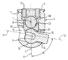
図1〜図3に示される第1の実施例に従った骨固定装置1は、ねじ付きシャフト3、および好ましくは球形セグメントの形をした頭部4を有するねじ部材2と、当該ねじ部材と接続されロッド100を受けるための受部5とを含む。当該頭部4は、その自由端に、捩じ込み工具との係合のための窪み4′を有する。当該受部5は、第1の端部6と、反対側の第2の端部7と、当該第1の端部6に開き第1のボア軸9を規定する第1のボア8とを有する。当該受部5は、さらに、ロッド100をその間に受けるための2つの自由な脚部を規定する実質的にU字型の窪み10を有する。雌ねじ11が当該脚部に設けられる。
The
当該受部は、第2のボア軸13を有する第2のボア12をさらに含み、当該第2のボア12は第1のボア8と連通しており、第1の端部6と第2の端部7との間の受部5の側面に開いている。
The receptacle further includes a
第2のボア軸13は、約90°±12°の角度αで、好ましくは90°よりもわずかに小さい角度、たとえば85°で第1のボア軸9と交差している。角度αは、受部5の底部から測定される。第2のボア12の直径は、頭部4の最大直径よりも小さいが、ねじ部材2のねじ付きシャフト3の直径よりも大きい。第2のボア12は受部5の外壁に隣接した部分14を備え、当該部分14の直径は外壁の方向に大きくなっている。当該直径は、たとえば、外壁に向かって広がる円錐状に大きくなっていてもよい。第2の端部7における受部5の底部に設けられた座部15には頭部4の一部が載り得る。好ましくは、当該座部15は、頭部4の球形の外面に適した球形を有する。
The
さらに、受部5は、第3のボア軸17を有する第3のボア16を含み、当該第3のボア16は第1のボア8と連通しており、第1の端部6と第2の端部7との間における、第2
のボア12と反対側の受部5の側面に開いている。好ましくは、第3のボア軸17は、第2のボア12の第2のボア軸13と同軸である。第3のボア17の直径は、頭部4の最大直径よりも大きく、このため、ねじ付きシャフト3の直径よりも大きい。第3のボア16は、第1のボア8と連通しているので、第2のボア12とも連通する。
Furthermore, the
Is open on the side of the
骨固定装置1はさらに圧力要素20を含む。当該圧力要素20が有する実質的に円筒形の外面の最大直径は、当該圧力要素20が第1のボア8内で動き得る程度に第1のボア8の内径よりも小さい。圧力要素20は、第1の端部7に面する側に球形の窪み21を含み、当該球形の窪み21の形は頭部4の球形面に適合している。その反対側に圧力要素が有する円筒形の窪みは、ロッド100が挿入される際に当該ロッド100の一部を受けるような形状および大きさである。さらに、圧力要素20は、円筒形の窪み22の円筒軸の両側であって球形の窪み21を有する端部に切欠23を含む。当該切欠23は、ねじ部材の頭部4が圧力要素20によって部分的に囲まれている場合にねじ付きシャフト3の回動を可能にするためのものである。図3から分かるように、当該切欠23は、骨固定装置が組立てられた状態であっても、ねじの頭部4の窪み4′へのアクセスを可能にするような大きさである。
The
骨固定装置はまた、受部の雌ねじ11と協働する雄ねじを備えたロックねじ25を含む。
The bone anchoring device also includes a
圧力要素20の寸法は、組立てられた状態で、ねじ部材2が受部5に挿入され、ロッド100が圧力要素に挿入され、ロックねじ25がまだ締められていない場合、圧力要素20の円筒形の窪み22の底部が受部5のU字型の窪みの底部の上方で突き出るようなものにされる。
The
当該骨固定装置は、まず、頭部4が座部15に載るまで、第3のボア16と当該第3のボア16と連通する第2のボア12とを通じてねじ付きシャフト3を差込むことによって組立てられる。次いで、圧力要素20は、その球形の窪み21と球形セグメントの頭部4の部分が係合するように動かされる。当該骨固定装置は、手術で用いられる前にこのような態様で予め組立てられてもよい。
The bone anchoring device first inserts the threaded
使用の際に、まず、受部5および圧力要素20と予め組立てられているねじ部材2は、第3のボア16を通じて届く捩じ込み工具と頭部の窪み4′とを係合させることによって骨に捩じ込まれる。第1のボア軸9は、ねじ部材2の長手方向の軸に対して、第2のボア12の直径の大きさと直径が大きくなっている部分14の大きさとに応じた少なくとも約10°±αであり得る角度をなす。同様に、ねじ部材2の長手方向の軸は、第1のボア軸9に対して垂直であり、かつロッド100の長手方向の軸Lに対して垂直である軸に対して±10°の角度をなし得る。したがって、ねじ部材2は、第2のボア軸13の周りの円錐内における±10°の角度範囲、第2のボア12および部分14の大きさに応じた角度範囲で回動可能となる。
In use, the
ロッド100が挿入され、ねじ部材2と受部5との間の角度位置が調節されると、ロックねじ25が捩じ込まれ、ロッド100に押し当てられて当該ロッドを固定し、同時に、ロッドを介して圧力部材20に押し当てられてねじ2の頭部をその位置に固定する。
When the
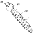
図4は、脊椎の仙腸関節領域における安定化システム内の骨固定装置の応用例を示す。複数の公知の固定装置101が各々、ロッド100に接続される。安定化システムのロッド100は仙骨50の領域に延在する。この発明に従った骨固定装置1は仙腸関節の固定に用いられる。このために、ねじ部材2は、長手方向のロッド軸Lと第1のボア軸9とを含む面から約90°の角度で延在する必要がある。ねじ部材2は、上述のとおり、±10
°の角度範囲内で第2のボア軸に対して回動可能である。
FIG. 4 shows an application example of the bone anchoring device in the stabilization system in the sacroiliac joint region of the spine. A plurality of known fixing
It is rotatable with respect to the second bore axis within an angle range of °.
図5〜図8は骨固定装置の第2の実施例を示す。第2の実施例の骨固定装置と第1の実施例の骨固定装置とは、受部の第2および第3のボアの構造が異なっている。他のすべての部分は第1の実施例と同一であり、第1の実施例と同じ参照番号が付されている。その説明は省略する。受部500は、第1のボア8と連通しており第2のボア軸130を規定する第2のボア120を含む。第1の実施例と同様に、第2のボア120は、受部500の側面に開いており、第2のボア軸130は、ロッド100の長手方向の軸と第1のボア軸9とによって規定される面から約90°の角度で延在している。第2のボア120の直径はねじ部材2の頭部4の最大直径よりも大きいので、頭部4が受部500の底部における座部15に載るまでねじ部材2の頭部4を、第2のボア120を通じて受部500に差込むことができる。第2のボア120の反対側に設けられる第3のボア160は第1のボア8と連通しており、第3のボア軸170を規定する。第3のボア軸170は好ましくは第2のボア軸130と同軸である。第3のボア160は側面に開いており、その直径は、頭部4の窪み4′との係合のために少なくとも捩じ込み工具を差込むことができるような大きさであるが、当該直径は当該頭部の最大直径よりも小さいので、ねじ部材は第3のボア160を通って抜け出すことはできない。第3のボア160は、第1のボア8と連通しているので、第2のボア120とも連通する。
5 to 8 show a second embodiment of the bone anchoring device. The bone anchoring device of the second embodiment and the bone anchoring device of the first embodiment are different in the structures of the second and third bores of the receiving part. All other parts are the same as in the first embodiment and are given the same reference numbers as in the first embodiment. The description is omitted. The
骨固定装置1は、図6aおよび図6bに図示のとおり、予め組立てられる。ここで、ねじ部材2の頭部4は、当該頭部4が座部15に載るまで第2のボア120を通じて差込まれている。次いで、使用の際に、ねじ部材2は、頭部の窪み4′に係合する捩じ込み工具を第3のボア160を通じて差込むことによって骨に捩じ込まれる。その後、受部500に対するねじ部材の角度位置が調節され、ロッドが挿入され、そして、ねじ25を捩じ込むことによって当該装置が固定される。
The
代替的な用途では、ねじ部材2は骨に捩じ込まれてもよく、その後、第2のボア120を通じてねじ部材の頭部を受部500に差込むことによって受部500がねじ部材2に接続されてもよい。
In an alternative application, the
図9〜図11は、第3の実施例に従った骨固定装置を示す。当該骨固定装置と第1の実施例に従った骨固定装置とは、骨固定要素の設計だけが異なっている。受部5は同一である。骨固定要素200はねじ付きシャフト3および頭部400を含む。当該頭部は、ねじ付きシャフト3とは反対側に六角形の突起401を含む。当該六角形の突起401は、第3のボア16を通じて差込まれ得る工具との係合のためのものである。これは、頭部を、窪みのない中実の球形または球形セグメントとして作製できるという利点を有する。当該突起は、工具との係合に適したいかなる形状であってもよい。さらなる変形例においては、突起自体は、工具との係合のための窪みを有する。
9 to 11 show a bone anchoring device according to a third embodiment. The bone anchoring device and the bone anchoring device according to the first embodiment differ only in the design of the bone anchoring element. The receiving
この発明の変形例は、たとえば、ねじ部材2がまず骨に捩じ込まれ、その後、受部500に接続される場合に第3のボア160を省くことができ得る第2の実施例の場合に可能となる。第2のボアの大きさは、受部に対してより広いかまたは狭い角度範囲で骨ねじ部材を回動させることを可能にするために異なっていてもよい。圧力要素における切欠23は、工具によるねじ頭部へのアクセスが可能であるならば省かれてもよい。代替的には、切欠は1つだけ設けられる。
The modification of the present invention is, for example, the case of the second embodiment in which the
予め組立てるために、クリンプ(crimp)ボアを介して圧力要素20を受部に接続することができる。
For pre-assembly, the
座部15は球形でなくてもよく、別の形状であるかまたは平坦であってもよい。閉鎖機
構として、単一のロックねじを用いる以外の機構も実現可能である。たとえば、ロッドロックねじや頭部ロックナット状の要素を含むロックアセンブリが実現可能である。この場合、圧力要素は、ロッドの上方に突き出る直立した脚部を備えており、このため、当該ロッドとは別個に押し下げられ得る。
The
当該シャフトはねじ山がなくてもよく、骨への保持を可能にする他のいかなる形状および構造であってもよい。圧力要素はまた平坦な円板の形状であってもよい。 The shaft may be threadless and may have any other shape and structure that allows it to be retained on the bone. The pressure element may also be in the form of a flat disc.
2 骨固定要素、3 シャフト、4 頭部、5 受部、8 第1のボア、9 第1のボア軸、10 窪み、12 第2のボア、13 第2のボア軸、20 圧力部材。 2 bone anchoring elements, 3 shafts, 4 heads, 5 receiving parts, 8 first bore, 9 first bore axis, 10 recess, 12 second bore, 13 second bore axis, 20 pressure member.
Claims (17)
骨に固定すべきシャフト(3)および頭部(4;400)を有する骨固定要素(2;200)と、
前記骨固定要素(2)に接続されロッド(100)を受けるための受部(5;500)とを含み、前記ロッドは長手方向の軸(L)を有し、
前記受部(5;500)は一体的に形成され、第1のボア軸(9)を備える開いた第1のボア(8)と、前記ロッドを受けるような形状および大きさの窪み(10)と、第2のボア軸(13;130)を有する第2のボア(12;120)とを有し、前記第2のボアは前記第1のボア(8)と連通しており、前記第2のボア(12、120)を通って延在する前記シャフト(3)の一部とともに前記頭部(4)を受けるような大きさであり、前記第2のボア軸(13;130)は、前記第1のボア軸(9)および前記ロッドの前記長手方向の軸(L)によって規定される面に対して約90°の角度をなし、前記骨固定装置はさらに、
前記受部に対して前記頭部(4;400)の位置を固定するよう前記頭部に作用する圧力部材(20)を含み、
前記圧力部材(20)は、前記ロッド(100)を受け入れる円筒形の窪み(22)と前記頭部(4)の球形面に適合する球形の窪み(21)とを備え、前記円筒形の窪み(22)の円筒軸は、前記第2のボア軸に対しても、約90°の角度をなすように構成され、さらに骨固定装置が組立てられた状態で前記頭部(4,400)へのアクセスを可能とする切欠(23)を備える、骨固定装置。 A bone anchoring device,
A bone fixation element (2; 200) having a shaft (3) and a head (4; 400) to be fixed to the bone;
A receiving part (5; 500) connected to the bone anchoring element (2) for receiving the rod (100), the rod having a longitudinal axis (L);
The receiving part (5; 500) is integrally formed and has an open first bore (8) with a first bore shaft (9) and a depression (10) shaped and sized to receive the rod. ) And a second bore (12; 120) having a second bore shaft (13; 130), said second bore communicating with said first bore (8), Sized to receive the head (4) with a portion of the shaft (3) extending through a second bore (12, 120), and the second bore shaft (13; 130) Is at an angle of about 90 ° with respect to a plane defined by the first bore axis (9) and the longitudinal axis (L) of the rod, the bone anchoring device further comprising:
Seen including a pressure member (20) acting on the head to fix the position of; (400 4), said head relative to the receiving part
The pressure member (20) comprises a cylindrical recess (22) that receives the rod (100) and a spherical recess (21) that fits the spherical surface of the head (4), the cylindrical recess. The cylindrical shaft of (22) is configured to form an angle of about 90 ° with respect to the second bore shaft, and further to the head (4,400) in a state where the bone fixing device is assembled. A bone anchoring device comprising a notch (23) allowing access to the bone.
Applications Claiming Priority (4)
| Application Number | Priority Date | Filing Date | Title |
|---|---|---|---|
| US79008406A | 2006-04-06 | 2006-04-06 | |
| EP06007324.4 | 2006-04-06 | ||
| US60/790,084 | 2006-04-06 | ||
| EP06007324A EP1842503B1 (en) | 2006-04-06 | 2006-04-06 | Angled polyaxial bone anchoring device |
Related Child Applications (1)
| Application Number | Title | Priority Date | Filing Date |
|---|---|---|---|
| JP2013019378A Division JP5695683B2 (en) | 2006-04-06 | 2013-02-04 | Bone fixation device |
Publications (2)
| Publication Number | Publication Date |
|---|---|
| JP2007275592A JP2007275592A (en) | 2007-10-25 |
| JP5291887B2 true JP5291887B2 (en) | 2013-09-18 |
Family
ID=36933600
Family Applications (2)
| Application Number | Title | Priority Date | Filing Date |
|---|---|---|---|
| JP2007097460A Expired - Fee Related JP5291887B2 (en) | 2006-04-06 | 2007-04-03 | Bone fixation device |
| JP2013019378A Expired - Fee Related JP5695683B2 (en) | 2006-04-06 | 2013-02-04 | Bone fixation device |
Family Applications After (1)
| Application Number | Title | Priority Date | Filing Date |
|---|---|---|---|
| JP2013019378A Expired - Fee Related JP5695683B2 (en) | 2006-04-06 | 2013-02-04 | Bone fixation device |
Country Status (8)
| Country | Link |
|---|---|
| US (2) | US8641737B2 (en) |
| EP (1) | EP1842503B1 (en) |
| JP (2) | JP5291887B2 (en) |
| KR (1) | KR101312688B1 (en) |
| CN (1) | CN101049257B (en) |
| DE (1) | DE602006009069D1 (en) |
| ES (1) | ES2333146T3 (en) |
| TW (1) | TWI413506B (en) |
Families Citing this family (79)
| Publication number | Priority date | Publication date | Assignee | Title |
|---|---|---|---|---|
| DE10055888C1 (en) * | 2000-11-10 | 2002-04-25 | Biedermann Motech Gmbh | Bone screw, has connector rod receiving part with unsymmetrically arranged end bores |
| US6974460B2 (en) | 2001-09-14 | 2005-12-13 | Stryker Spine | Biased angulation bone fixation assembly |
| US20070156241A1 (en) | 2004-08-09 | 2007-07-05 | Reiley Mark A | Systems and methods for the fixation or fusion of bone |
| US9949843B2 (en) | 2004-08-09 | 2018-04-24 | Si-Bone Inc. | Apparatus, systems, and methods for the fixation or fusion of bone |
| US8425570B2 (en) | 2004-08-09 | 2013-04-23 | Si-Bone Inc. | Apparatus, systems, and methods for achieving anterior lumbar interbody fusion |
| US8388667B2 (en) | 2004-08-09 | 2013-03-05 | Si-Bone, Inc. | Systems and methods for the fixation or fusion of bone using compressive implants |
| US8414648B2 (en) | 2004-08-09 | 2013-04-09 | Si-Bone Inc. | Apparatus, systems, and methods for achieving trans-iliac lumbar fusion |
| US9662158B2 (en) | 2004-08-09 | 2017-05-30 | Si-Bone Inc. | Systems and methods for the fixation or fusion of bone at or near a sacroiliac joint |
| US20180228621A1 (en) | 2004-08-09 | 2018-08-16 | Mark A. Reiley | Apparatus, systems, and methods for the fixation or fusion of bone |
| DE102005053819A1 (en) * | 2005-11-11 | 2007-05-16 | Khd Humboldt Wedag Gmbh | Rotary kiln burner |
| EP2211742A4 (en) | 2007-10-24 | 2012-12-19 | Nuvasive Inc | Surgical fixation system and related methods |
| US8007522B2 (en) | 2008-02-04 | 2011-08-30 | Depuy Spine, Inc. | Methods for correction of spinal deformities |
| US9060813B1 (en) | 2008-02-29 | 2015-06-23 | Nuvasive, Inc. | Surgical fixation system and related methods |
| US8506601B2 (en) * | 2008-10-14 | 2013-08-13 | Pioneer Surgical Technology, Inc. | Low profile dual locking fixation system and offset anchor member |
| ES2374516T3 (en) | 2009-07-28 | 2012-02-17 | Biedermann Motech Gmbh | BONE ANCHORAGE DEVICE. |
| US20110098816A1 (en) * | 2009-10-28 | 2011-04-28 | Warsaw Orthopedic, Inc. | Sacro-iliac joint implant system and method |
| US20110098817A1 (en) * | 2009-10-28 | 2011-04-28 | Warsaw Orthopedic, Inc. | Sacro-iliac joint implant system and method |
| US20110106181A1 (en) * | 2009-10-30 | 2011-05-05 | Warsaw Orthopedic, Inc. | Adjustable saddle for a bone anchor |
| WO2012174485A1 (en) | 2011-06-17 | 2012-12-20 | Jcbd, Llc | Sacroiliac joint implant system |
| BR112012017259A2 (en) | 2010-01-13 | 2016-08-23 | Jcbd Llc | sacroiliac joint fusion and fixation system |
| US9381045B2 (en) | 2010-01-13 | 2016-07-05 | Jcbd, Llc | Sacroiliac joint implant and sacroiliac joint instrument for fusing a sacroiliac joint |
| US9333090B2 (en) | 2010-01-13 | 2016-05-10 | Jcbd, Llc | Systems for and methods of fusing a sacroiliac joint |
| WO2014015309A1 (en) | 2012-07-20 | 2014-01-23 | Jcbd, Llc | Orthopedic anchoring system and methods |
| US9421109B2 (en) | 2010-01-13 | 2016-08-23 | Jcbd, Llc | Systems and methods of fusing a sacroiliac joint |
| US20110184518A1 (en) * | 2010-01-22 | 2011-07-28 | Warsaw Orthopedic, Inc. | Sacro-iliac joint implant |
| US8221428B2 (en) * | 2010-01-26 | 2012-07-17 | Warsaw Orthopedic, Inc. | Sacro-iliac joint implant system, method and instrument |
| US20110184520A1 (en) * | 2010-01-27 | 2011-07-28 | Warsaw Orthopedic, Inc. | Sacro-iliac joint implant, method and apparatus |
| US8945224B2 (en) * | 2010-03-18 | 2015-02-03 | Warsaw, Orthopedic, Inc. | Sacro-iliac implant system, method and apparatus |
| US20110238181A1 (en) * | 2010-03-29 | 2011-09-29 | Warsaw Orthopedic, Inc., A Indiana Corporation | Sacro-iliac joint implant system and method |
| US9039765B2 (en) | 2011-01-21 | 2015-05-26 | Warsaw Orhtopedic, Inc. | Implant system and method for stabilization of a sacro-iliac joint |
| US9387013B1 (en) | 2011-03-01 | 2016-07-12 | Nuvasive, Inc. | Posterior cervical fixation system |
| US9763704B2 (en) | 2011-08-31 | 2017-09-19 | DePuy Synthes Products, Inc. | System and method for cervical midline fixation |
| US8940023B2 (en) * | 2011-08-31 | 2015-01-27 | DePuy Synthes Products, LLC | System and method for cervical midline fixation |
| EP2606841B1 (en) * | 2011-12-23 | 2016-03-09 | Biedermann Technologies GmbH & Co. KG | Polyaxial bone anchoring device |
| CN104334102A (en) | 2012-03-09 | 2015-02-04 | 西-博恩公司 | Integrated implant |
| US10363140B2 (en) | 2012-03-09 | 2019-07-30 | Si-Bone Inc. | Systems, device, and methods for joint fusion |
| CZ2012192A3 (en) * | 2012-03-16 | 2013-09-25 | Srámek@Jirí | Transpedicular polyaxial screw |
| CN104334092A (en) | 2012-05-04 | 2015-02-04 | 西-博恩公司 | Fenestrated implant |
| US10179014B1 (en) | 2012-06-01 | 2019-01-15 | Nuvasive, Inc. | Systems and methods for promoting sacroiliac joint fusion |
| ES2606151T3 (en) * | 2012-07-27 | 2017-03-22 | Biedermann Technologies Gmbh & Co. Kg | Polyaxial bone anchoring device with extended turning angle |
| DE202012103384U1 (en) | 2012-09-05 | 2012-09-24 | Signus Medizintechnik Gmbh | Pelvic ring implant |
| US9782204B2 (en) | 2012-09-28 | 2017-10-10 | Medos International Sarl | Bone anchor assemblies |
| ES2556462T3 (en) * | 2012-12-10 | 2016-01-18 | Biedermann Technologies Gmbh & Co. Kg | Anchoring element suitable for use in a polyaxial bone anchoring device and polyaxial bone anchoring device with an enlarged angle of rotation to one side |
| US9724149B2 (en) | 2013-03-07 | 2017-08-08 | Warsaw Orhtopedic, Inc. | Surgical implant system and method |
| US9259247B2 (en) | 2013-03-14 | 2016-02-16 | Medos International Sarl | Locking compression members for use with bone anchor assemblies and methods |
| US9775660B2 (en) | 2013-03-14 | 2017-10-03 | DePuy Synthes Products, Inc. | Bottom-loading bone anchor assemblies and methods |
| US20140277153A1 (en) | 2013-03-14 | 2014-09-18 | DePuy Synthes Products, LLC | Bone Anchor Assemblies and Methods With Improved Locking |
| US9724145B2 (en) | 2013-03-14 | 2017-08-08 | Medos International Sarl | Bone anchor assemblies with multiple component bottom loading bone anchors |
| US10342582B2 (en) | 2013-03-14 | 2019-07-09 | DePuy Synthes Products, Inc. | Bone anchor assemblies and methods with improved locking |
| WO2014146018A1 (en) | 2013-03-15 | 2014-09-18 | Jcbd, Llc | Systems and methods for fusing a sacroiliac joint and anchoring an orthopedic appliance |
| WO2014145902A1 (en) | 2013-03-15 | 2014-09-18 | Si-Bone Inc. | Implants for spinal fixation or fusion |
| US9510872B2 (en) | 2013-03-15 | 2016-12-06 | Jcbd, Llc | Spinal stabilization system |
| US9717539B2 (en) | 2013-07-30 | 2017-08-01 | Jcbd, Llc | Implants, systems, and methods for fusing a sacroiliac joint |
| US10245087B2 (en) | 2013-03-15 | 2019-04-02 | Jcbd, Llc | Systems and methods for fusing a sacroiliac joint and anchoring an orthopedic appliance |
| US9826986B2 (en) | 2013-07-30 | 2017-11-28 | Jcbd, Llc | Systems for and methods of preparing a sacroiliac joint for fusion |
| WO2015017593A1 (en) | 2013-07-30 | 2015-02-05 | Jcbd, Llc | Systems for and methods of fusing a sacroiliac joint |
| US11147688B2 (en) | 2013-10-15 | 2021-10-19 | Si-Bone Inc. | Implant placement |
| US9839448B2 (en) | 2013-10-15 | 2017-12-12 | Si-Bone Inc. | Implant placement |
| JP2017511192A (en) | 2014-04-10 | 2017-04-20 | メダクタ・インターナショナル・ソシエテ・アノニム | Fixation device for fixing the surgical implant in place, and the process of attaching this fixation device to the anchor means |
| US9801546B2 (en) | 2014-05-27 | 2017-10-31 | Jcbd, Llc | Systems for and methods of diagnosing and treating a sacroiliac joint disorder |
| WO2016044731A1 (en) | 2014-09-18 | 2016-03-24 | Si-Bone Inc. | Implants for bone fixation or fusion |
| WO2016044739A1 (en) | 2014-09-18 | 2016-03-24 | Si-Bone Inc. | Matrix implant |
| US10149702B2 (en) | 2015-01-12 | 2018-12-11 | Imds Llc | Polyaxial screw and rod system |
| US10376206B2 (en) | 2015-04-01 | 2019-08-13 | Si-Bone Inc. | Neuromonitoring systems and methods for bone fixation or fusion procedures |
| US10034691B1 (en) | 2015-12-03 | 2018-07-31 | Nuvasive, Inc. | Bone anchor |
| US10667923B2 (en) | 2016-10-31 | 2020-06-02 | Warsaw Orthopedic, Inc. | Sacro-iliac joint implant system and method |
| EP3974021B1 (en) | 2017-06-30 | 2023-06-14 | ONWARD Medical N.V. | A system for neuromodulation |
| US10603055B2 (en) | 2017-09-15 | 2020-03-31 | Jcbd, Llc | Systems for and methods of preparing and fusing a sacroiliac joint |
| WO2019067584A1 (en) | 2017-09-26 | 2019-04-04 | Si-Bone Inc. | Systems and methods for decorticating the sacroiliac joint |
| DE18205821T1 (en) | 2018-11-13 | 2020-12-24 | Gtx Medical B.V. | CONTROL SYSTEM FOR MOTION RECONSTRUCTION AND / OR RECOVERY FOR A PATIENT |
| EP3695878B1 (en) | 2019-02-12 | 2023-04-19 | ONWARD Medical N.V. | A system for neuromodulation |
| US11369419B2 (en) | 2019-02-14 | 2022-06-28 | Si-Bone Inc. | Implants for spinal fixation and or fusion |
| JP2022520101A (en) | 2019-02-14 | 2022-03-28 | エスアイ-ボーン・インコーポレイテッド | Implants for spinal fixation and / or fusion |
| US11564812B2 (en) | 2019-09-09 | 2023-01-31 | Warsaw Orthopedic, Inc. | Surgical instrument and method |
| US11344354B2 (en) | 2019-09-09 | 2022-05-31 | Warsaw Orthopedic, Inc. | Surgical instrument and method |
| WO2021108590A1 (en) | 2019-11-27 | 2021-06-03 | Si-Bone, Inc. | Bone stabilizing implants and methods of placement across si joints |
| DE19211698T1 (en) | 2019-11-27 | 2021-09-02 | Onward Medical B.V. | Neuromodulation system |
| EP3878386B1 (en) | 2020-03-12 | 2023-08-30 | Biedermann Technologies GmbH & Co. KG | Coupling device for use with a bone anchoring element and bone anchoring device with such a coupling device |
| JP2023553120A (en) | 2020-12-09 | 2023-12-20 | エスアイ-ボーン・インコーポレイテッド | Sacroiliac joint stabilization implants and implant methods |
Family Cites Families (19)
| Publication number | Priority date | Publication date | Assignee | Title |
|---|---|---|---|---|
| US5776135A (en) * | 1996-12-23 | 1998-07-07 | Third Millennium Engineering, Llc | Side mounted polyaxial pedicle screw |
| FR2796546B1 (en) * | 1999-07-23 | 2001-11-30 | Eurosurgical | POLYAXIAL CONNECTOR FOR SPINAL IMPLANT |
| US6443953B1 (en) * | 2000-02-08 | 2002-09-03 | Cross Medical Products, Inc. | Self-aligning cap nut for use with a spinal rod anchor |
| DE10055888C1 (en) | 2000-11-10 | 2002-04-25 | Biedermann Motech Gmbh | Bone screw, has connector rod receiving part with unsymmetrically arranged end bores |
| US6520963B1 (en) * | 2001-08-13 | 2003-02-18 | Mckinley Lawrence M. | Vertebral alignment and fixation assembly |
| US6974460B2 (en) | 2001-09-14 | 2005-12-13 | Stryker Spine | Biased angulation bone fixation assembly |
| US6837889B2 (en) * | 2002-03-01 | 2005-01-04 | Endius Incorporated | Apparatus for connecting a longitudinal member to a bone portion |
| US20040210216A1 (en) * | 2003-04-17 | 2004-10-21 | Farris Robert A | Spinal fixation system and method |
| US6981973B2 (en) * | 2003-08-11 | 2006-01-03 | Mckinley Laurence M | Low profile vertebral alignment and fixation assembly |
| US20050154393A1 (en) * | 2003-12-30 | 2005-07-14 | Thomas Doherty | Bone anchor assemblies and methods of manufacturing bone anchor assemblies |
| EP1699371A4 (en) | 2003-12-30 | 2008-09-24 | Depuy Spine Sarl | Bone anchor assemblies |
| US7678137B2 (en) * | 2004-01-13 | 2010-03-16 | Life Spine, Inc. | Pedicle screw constructs for spine fixation systems |
| EP1814470B1 (en) * | 2004-11-23 | 2011-12-14 | Roger P. Jackson | Polyaxial bone screw with multi-part shank retainer |
| US7674277B2 (en) * | 2004-12-01 | 2010-03-09 | Warsaw Orthopedic, Inc. | Side-loading bone anchor |
| US8167913B2 (en) * | 2005-03-03 | 2012-05-01 | Altus Partners, Llc | Spinal stabilization using bone anchor and anchor seat with tangential locking feature |
| TWM285330U (en) * | 2005-08-30 | 2006-01-11 | Microware Prec Co Ltd | Innovated structure for self-tapping bone screw |
| US20070083206A1 (en) | 2005-09-21 | 2007-04-12 | Microware Precision Co., Ltd. | Self drilling and tapping bone screw |
| US7850716B2 (en) * | 2006-02-17 | 2010-12-14 | Warsaw Orthopedic, Inc. | Adjustable interconnection device |
| FR2931054A1 (en) * | 2008-05-13 | 2009-11-20 | Warsaw Orthopedic Inc | SPINAL CONNECTOR SYSTEM AND SPINAL SURGICAL SYSTEM USING THE SAME |
-
2006
- 2006-04-06 ES ES06007324T patent/ES2333146T3/en active Active
- 2006-04-06 DE DE602006009069T patent/DE602006009069D1/en active Active
- 2006-04-06 EP EP06007324A patent/EP1842503B1/en not_active Not-in-force
-
2007
- 2007-04-03 KR KR1020070032936A patent/KR101312688B1/en not_active IP Right Cessation
- 2007-04-03 JP JP2007097460A patent/JP5291887B2/en not_active Expired - Fee Related
- 2007-04-03 TW TW096111730A patent/TWI413506B/en not_active IP Right Cessation
- 2007-04-03 CN CN200710091622XA patent/CN101049257B/en not_active Expired - Fee Related
- 2007-04-05 US US11/697,220 patent/US8641737B2/en not_active Expired - Fee Related
-
2013
- 2013-02-04 JP JP2013019378A patent/JP5695683B2/en not_active Expired - Fee Related
-
2014
- 2014-01-06 US US14/147,846 patent/US20140222079A1/en not_active Abandoned
Also Published As
| Publication number | Publication date |
|---|---|
| KR101312688B1 (en) | 2013-10-14 |
| JP2013116336A (en) | 2013-06-13 |
| JP5695683B2 (en) | 2015-04-08 |
| JP2007275592A (en) | 2007-10-25 |
| EP1842503A1 (en) | 2007-10-10 |
| DE602006009069D1 (en) | 2009-10-22 |
| ES2333146T3 (en) | 2010-02-17 |
| TW200738208A (en) | 2007-10-16 |
| CN101049257B (en) | 2011-05-04 |
| US8641737B2 (en) | 2014-02-04 |
| EP1842503B1 (en) | 2009-09-09 |
| US20070265621A1 (en) | 2007-11-15 |
| KR20070100123A (en) | 2007-10-10 |
| CN101049257A (en) | 2007-10-10 |
| TWI413506B (en) | 2013-11-01 |
| US20140222079A1 (en) | 2014-08-07 |
Similar Documents
| Publication | Publication Date | Title |
|---|---|---|
| JP5291887B2 (en) | Bone fixation device | |
| US8784455B2 (en) | Bone anchoring device | |
| EP1743584B1 (en) | Bone anchoring device | |
| JP4994773B2 (en) | Bone fixation device | |
| US7892259B2 (en) | Bone anchoring device | |
| US7972364B2 (en) | Locking assembly for securing a rod member in a receiver part for use in spinal or trauma surgery, bone anchoring device with such a locking assembly and tool therefor | |
| JP5361161B2 (en) | Bone fixation device | |
| US9192417B2 (en) | Monoplanar bone anchoring device with selectable pivot plane | |
| JP2008049166A (en) | Bone anchoring device |
Legal Events
| Date | Code | Title | Description |
|---|---|---|---|
| A621 | Written request for application examination |
Free format text: JAPANESE INTERMEDIATE CODE: A621 Effective date: 20100115 |
|
| A131 | Notification of reasons for refusal |
Free format text: JAPANESE INTERMEDIATE CODE: A131 Effective date: 20120228 |
|
| A977 | Report on retrieval |
Free format text: JAPANESE INTERMEDIATE CODE: A971007 Effective date: 20120229 |
|
| A601 | Written request for extension of time |
Free format text: JAPANESE INTERMEDIATE CODE: A601 Effective date: 20120524 |
|
| A602 | Written permission of extension of time |
Free format text: JAPANESE INTERMEDIATE CODE: A602 Effective date: 20120529 |
|
| A601 | Written request for extension of time |
Free format text: JAPANESE INTERMEDIATE CODE: A601 Effective date: 20120627 |
|
| A602 | Written permission of extension of time |
Free format text: JAPANESE INTERMEDIATE CODE: A602 Effective date: 20120702 |
|
| A02 | Decision of refusal |
Free format text: JAPANESE INTERMEDIATE CODE: A02 Effective date: 20121002 |
|
| A711 | Notification of change in applicant |
Free format text: JAPANESE INTERMEDIATE CODE: A711 Effective date: 20121219 |
|
| A521 | Written amendment |
Free format text: JAPANESE INTERMEDIATE CODE: A523 Effective date: 20130204 |
|
| A911 | Transfer to examiner for re-examination before appeal (zenchi) |
Free format text: JAPANESE INTERMEDIATE CODE: A911 Effective date: 20130319 |
|
| A01 | Written decision to grant a patent or to grant a registration (utility model) |
Free format text: JAPANESE INTERMEDIATE CODE: A01 Effective date: 20130521 |
|
| A61 | First payment of annual fees (during grant procedure) |
Free format text: JAPANESE INTERMEDIATE CODE: A61 Effective date: 20130610 |
|
| LAPS | Cancellation because of no payment of annual fees |