JP5288552B2 - Tuning device - Google Patents
Tuning device Download PDFInfo
- Publication number
- JP5288552B2 JP5288552B2 JP2009027423A JP2009027423A JP5288552B2 JP 5288552 B2 JP5288552 B2 JP 5288552B2 JP 2009027423 A JP2009027423 A JP 2009027423A JP 2009027423 A JP2009027423 A JP 2009027423A JP 5288552 B2 JP5288552 B2 JP 5288552B2
- Authority
- JP
- Japan
- Prior art keywords
- tuning
- display area
- reference position
- display
- tuning device
- Prior art date
- Legal status (The legal status is an assumption and is not a legal conclusion. Google has not performed a legal analysis and makes no representation as to the accuracy of the status listed.)
- Expired - Fee Related
Links
- 230000001133 acceleration Effects 0.000 claims description 8
- 239000003086 colorant Substances 0.000 claims description 7
- 230000033764 rhythmic process Effects 0.000 claims description 4
- 125000004122 cyclic group Chemical group 0.000 description 3
- 239000000463 material Substances 0.000 description 3
- 238000000605 extraction Methods 0.000 description 2
- 230000001902 propagating effect Effects 0.000 description 2
- 230000000630 rising effect Effects 0.000 description 2
- 229910001369 Brass Inorganic materials 0.000 description 1
- 239000010951 brass Substances 0.000 description 1
- 238000001514 detection method Methods 0.000 description 1
- 230000006870 function Effects 0.000 description 1
- 238000009499 grossing Methods 0.000 description 1
- 239000004973 liquid crystal related substance Substances 0.000 description 1
- 239000011347 resin Substances 0.000 description 1
- 229920005989 resin Polymers 0.000 description 1
Images


Landscapes
- Auxiliary Devices For Music (AREA)
Description
本発明は、音楽の演奏時(演奏開始前)や練習時に用いられる調律装置に関するものである。 The present invention relates to a tuning device used at the time of music performance (before performance start) or at the time of practice.
従来から、音楽の演奏時や練習時に用いられ、任意の音を入力してその音高情報を基準として調律を行う調律装置が知られている。 2. Description of the Related Art Conventionally, a tuning device is known that is used when playing music or practicing and that tunes on the basis of pitch information by inputting an arbitrary sound.
この調律装置は、楽器に直接取り付けて楽器から発生した音の調律状態を調律装置本体の表示部に表示をするものであり、従来の調律装置は、調律対象である楽器から発せられる音を効率良く感知する場所を探りながら設置する必要があった。調律対象が金管楽器の場合、ベル付近の発音側が最も効率の良い採音ができる位置であるが、この位置に調律装置を設置すると、調律装置本体の表示面がベルに隠れてしまうという問題があった。このような問題を解消するために、楽器の発音部近傍を挟持するクリップ部と、調律した結果を表示する表示面を備えた調律装置本体との間に回動可能な継手を設け、表示面が演奏者から視認し易い位置に配置可能な調律装置が提案されている(例えば、特許文献1参照)。
This tuning device is directly attached to a musical instrument and displays the tuning state of the sound generated from the musical instrument on the display unit of the tuning device main body. The conventional tuning device is efficient for the sound emitted from the musical instrument to be tuned. It was necessary to install it while searching for a well-detected place. When the tuning target is a brass instrument, the sounding side near the bell is the position where the most efficient sound collection is possible, but if the tuning device is installed at this position, the display surface of the tuning device main body will be hidden by the bell there were. In order to solve such a problem, a rotatable joint is provided between the clip portion that holds the vicinity of the sound generating portion of the instrument and the tuning device main body having a display surface that displays the tuning result, and the display surface Has been proposed (see
しかしながら、上記特許文献1の調律装置においては、クリップ部と調律装置本体とが屈曲可能な継ぎ手によって接続されているものの、調律装置本体の表示部の向きを自由に変更することはできず、クリップの楽器への取り付け位置によっては表示部が反転した状態で設置される。
このように表示部が反転状態となると、特にセント表示の場合には音の高低が逆方向に表示されるため、楽器から生じる音が基準音に対して高いのか低いのかが認識しにくい。
However, in the tuning device of
In this way, when the display unit is reversed, particularly in the case of cent display, the pitch of the sound is displayed in the reverse direction, so it is difficult to recognize whether the sound generated from the instrument is higher or lower than the reference sound.
これを改善すべく、表示部におけるセント表示の高低を、ノーマル表示モードとミラー表示モードとで入れ換えることができる調律装置が提案されている(例えば、特許文献2参照)。即ち、この調律装置においては、ノーマル表示モードの際に左側が低セント、右側が高セントとなっているセント表示が、リバースボタンを押すことによって左側が高セント、右側が低セントとなるように入れ換わる。これによって、表示部の上下が逆になった場合であっても、演奏者が違和感なく調律状態を認識することができる。 In order to improve this, there has been proposed a tuning device capable of switching the height of the cent display on the display unit between the normal display mode and the mirror display mode (see, for example, Patent Document 2). That is, in this tuning device, in the normal display mode, the cent display in which the left side is low cent and the right side is high cent is set so that the left side becomes high cent and the right side becomes low cent by pressing the reverse button. Replace. Thus, even if the display unit is turned upside down, the player can recognize the tuning state without a sense of incongruity.
ところで、上記特許文献2に記載の調律装置は、表示部が上下反転した際にのみセント表示の高低を違和感なく認識可能とするものの、例えば、表示部が縦や斜めに配置された際にはセント表示の高低を認識しにくい。特に楽器の形状や取り付け位置によっては、表示部のセント表示を水平方向に沿わせて配置することが困難となる場合があり、セント表示を違和感なく認識して調律を円滑に行う妨げとなっていた。 By the way, the tuning device described in Patent Document 2 makes it possible to recognize the height of the cent display without a sense of incongruity only when the display unit is turned upside down. For example, when the display unit is arranged vertically or diagonally, It is difficult to recognize the height of the cent display. In particular, depending on the shape and mounting position of the instrument, it may be difficult to arrange the cent display on the display unit along the horizontal direction. This prevents the cent display from being uncomfortable and smoothing the tuning. It was.
この発明はこのような課題に鑑みてなされたものであって、楽器への取り付け位置や表示部の向きにかかわらず、演奏者が違和感なく調律状態を認識することができる調律装置を提供することを目的とする。 The present invention has been made in view of such a problem, and provides a tuning device that allows a player to recognize a tuning state without a sense of incongruity regardless of the mounting position on a musical instrument or the orientation of a display unit. With the goal.
上記課題に鑑みて、本発明は以下の手段を提案している。
即ち、本発明に係る調律装置は、楽器の音の基本周波数と比較の基準となる基準周波数との偏差を測定し、その偏差をセント表示として表示する調律装置において、複数の発光体が円周上に配置されてなる環状表示部を備え、前記発光体のうち、一の前記発光体が前記偏差0の調律基準位置とされ、前記調律基準位置の一方側の複数の前記発光体が前記偏差が−となる低表示域とされるとともに前記調律基準位置の他方側の複数の前記発光体が前記偏差が+となる高表示域とされ、前記環状表示部の上下を認識する上下認識手段を備え、前記環状表示部の上下が変化した場合に、前記上下認識手段の出力に基づいて、前記調律基準位置とされる前記発光体が変化し、上下方向に対する前記円周上の位置関係が所定位置となる一の前記発光体が調律基準位置とされ、前記環状表示部の上下が変化した場合に、前記上下認識手段の出力に基づいて、新たに前記所定位置となった前記発光体が前記調律基準位置とされることを特徴としている。
In view of the above problems, the present invention proposes the following means.
That is, the tuning device according to the present invention measures the deviation between the fundamental frequency of the sound of the musical instrument and the reference frequency to be compared, and displays the deviation as a cent display. An annular display unit disposed on the light emitting body, wherein one of the light emitters is set as a tuning reference position with a deviation of 0, and a plurality of the light emitting bodies on one side of the tuning reference position is the deviation. And a vertical display means for recognizing the upper and lower sides of the annular display section, wherein the plurality of light emitters on the other side of the tuning reference position are set to a high display area where the deviation is +. And when the upper and lower sides of the annular display portion are changed, the illuminant which is the tuning reference position is changed based on the output of the upper and lower recognition means, and the positional relationship on the circumference with respect to the vertical direction is predetermined. The one illuminant that becomes the position is Is a law reference position, wherein when the top and bottom of the annular display unit is changed, based on an output of said upper and lower recognition means, that the light emitters becomes newly the predetermined position is with the rhythm reference position It is said.
このような特徴の調律装置によれば、環状表示部の上下が変化した場合に上下認識手段が上下を認識し、この出力に基づいて調律基準位置となる発光体が変化するため、環状表示部の上下方向が変わっても、演奏者が違和感なく調律状態を認識することができる。
また、環状表示部の上下にかかわらず、上下方向に対する円周上の位置関係が所定位置となる発光体が常に調律基準位置とされ、該調律基準位置の両側に低表示域、高表示域が配置されることとなる。したがって、環状表示部の上下が変化した場合であっても、演奏者から見て常に同一位置に同様のセント表示を表示することができる。
According to the tuning device having such a feature, when the top and bottom of the annular display section changes, the top and bottom recognition means recognizes the top and bottom, and the illuminant that serves as the tuning reference position changes based on this output. Even if the vertical direction of the player changes, the performer can recognize the tuning state without a sense of incongruity.
Regardless of the upper and lower sides of the annular display portion, the light emitter whose circumferential positional relationship with respect to the vertical direction is a predetermined position is always the tuning reference position, and the low display area and the high display area are provided on both sides of the tuning reference position. Will be placed. Therefore, even when the upper and lower sides of the annular display portion are changed, the same cent display can always be displayed at the same position as viewed from the performer.
また、本発明に係る調律装置においては、前記所定位置が、上下方向に対する前記円周上の位置関係における最上位置又は最下位置であることが好ましい。
これによって、演奏者が調律基準位置を容易に把握することができるため、違和感なく調律状態を認識することができる。
In the tuning device according to the present invention, it is preferable that the predetermined position is an uppermost position or a lowermost position in a positional relationship on the circumference with respect to the vertical direction.
Thus, the performer can easily grasp the tuning reference position, and thus the tuning state can be recognized without a sense of incongruity.
また、本発明に係る調律装置においては、楽器の音が入力されない待機状態において、前記調律基準位置、前記低表示域及び前記高表示域のそれぞれの前記発光体が半点灯していることが好ましい。 In the tuning device according to the present invention, it is preferable that each of the light emitting bodies of the tuning reference position, the low display area, and the high display area is semi-lighted in a standby state in which no instrument sound is input. .
これによって、待機状態において調律の際にセント表示の取り得る範囲を示すことができるため、調律時に楽器の基本周波数を容易に認識することが可能となる。 As a result, the range that can be displayed by the cent display during tuning in the standby state can be shown, so that the fundamental frequency of the musical instrument can be easily recognized during tuning.
さらに、本発明に係る調律装置においては、前記低表示域の前記発光体と前記高表示域の前記発光体とが互いに異なる色彩で発光することを特徴とする。 Furthermore, in the tuning device according to the present invention, the light emitting body in the low display area and the light emitting body in the high display area emit light in different colors.
このような特徴の調律装置によれば、一方側が低表示域、他方側が高表示域といったように方向によって楽器の基本周波数を認識するのに加えて、色彩の違いによって高低を認識することができるため、楽器の基本周波数の認識をより容易に行うことができる。 According to the tuning device having such a feature, in addition to recognizing the fundamental frequency of a musical instrument according to the direction, such as a low display area on one side and a high display area on the other side, it is possible to recognize the height based on the difference in color. Therefore, the fundamental frequency of the musical instrument can be recognized more easily.
また、本発明に係る調律装置は、前記低表示域及び前記高表示域の前記発光体の発光色の濃淡が、前記一方側から前記他方側に向かうに従って連続的に変化するものであってもよい。 Further, the tuning device according to the present invention may be such that the intensity of the light emission color of the light emitter in the low display area and the high display area changes continuously from the one side toward the other side. Good.
このような特徴の調律装置によれば、一方側が低表示域、他方側が高表示域といったように方向によって楽器の基本周波数を認識するのに加えて、色彩の濃淡よって高低を認識することができるため、楽器の基本周波数の認識をより容易に行うことができる。 According to the tuning device having such a feature, in addition to recognizing the fundamental frequency of the instrument by the direction such that the one side is a low display area and the other side is a high display area, it is possible to recognize the high and low by the shade of color. Therefore, the fundamental frequency of the musical instrument can be recognized more easily.
さらに、本発明の調律装置は、前記環状表示部の中心軸回りに回転可能に取り付けられ、前記調律基準位置を示すマークが記載された表示パネルを備え、該表示パネルが前記調律基準位置の変化に追従して回転するように構成されていることを特徴としている。 Furthermore, the tuning device of the present invention is provided with a display panel that is rotatably mounted around the center axis of the annular display portion and has a mark indicating the tuning reference position, and the display panel changes the tuning reference position. It is characterized by being configured to rotate following the above.
このような特徴の調律装置においては、表示パネルのマークによって調律基準位置を容易に把握することができる。また、環状表示部の上下方向の変化に伴って調律基準位置が変化した場合であっても、表示パネルが当該変化に追従するように回転することから、該表示パネルのマークでもって常に調律基準位置を指し示すことができる。 In the tuning device having such characteristics, the tuning reference position can be easily grasped by the mark on the display panel. Even when the tuning reference position changes with the vertical change of the annular display portion, the display panel always rotates with the mark on the display panel because the display panel rotates to follow the change. The position can be indicated.
さらにまた、本発明の調律装置は、前記環状表示部の中心軸回りに回転可能に取り付けられ、前記低表示域及び前記高表示域の各前記発光体に対応する箇所にそれぞれ貫通孔を有する孔空きパネルを備え、前記貫通孔の直径が前記一方側から前記他方側に向かうに従って漸次大きくなるように形成され、前記孔空きパネルが前記調律基準位置に追従して回転するように構成されていることを特徴とする。 Furthermore, the tuning device of the present invention is attached so as to be rotatable about the central axis of the annular display portion, and has a through hole at a location corresponding to each of the light emitters in the low display area and the high display area. with an empty panel, the diameter of the through hole is formed so as gradually increases toward the said other side in from the one side, the perforated panels are configured to rotate to follow the rhythm reference position It is characterized by.
このような特徴の調律装置によれば、貫通孔の大小の違いによって楽器の基本周波数の高低を容易に認識することができる。また、環状表示部の上下の変化に伴って調律基準位置が変化した場合であっても、孔空きパネルが当該変化に追従するように回転することから、大小の貫通孔でもって常に楽器の基本周波数の高低を示すことができる。 According to the tuning device having such a feature, the level of the fundamental frequency of the musical instrument can be easily recognized by the difference in the size of the through hole. In addition, even if the tuning reference position changes as the annular display changes up and down, the perforated panel rotates so as to follow the change. The frequency can be shown.
また、本発明に係る調律装置においては、前記上下認識手段が、ウエイトが最下方に位置するように回転軸が回転して上下方向を認識する振り子機構であることを特徴としている。これによって、環状表示部の上下に関わらずウエイトが最下方に位置することにより、上下認識を確実に認識することができる。 In the tuning device according to the present invention, the vertical recognition means is a pendulum mechanism that recognizes the vertical direction by rotating the rotation shaft so that the weight is positioned at the lowest position. As a result, the weight is positioned at the lowermost position regardless of the top and bottom of the annular display portion, so that the top and bottom recognition can be reliably recognized.
さらに、本発明の調律装置においては、前記上下認識手段が、上下が変化する際の加速度を検知することにより上下方向を認識する加速度センサーであってもよい。この場合、環状表示部の上下が変化する際の加速度を検知することで、表示面の上下方向を認識することが可能となる。 Furthermore, in the tuning device of the present invention, the vertical recognition means may be an acceleration sensor that recognizes the vertical direction by detecting the acceleration when the vertical movement changes. In this case, it is possible to recognize the vertical direction of the display surface by detecting the acceleration when the vertical direction of the annular display portion changes.
本発明の調律装置によれば、環状表示部の上下が変化した場合であっても、演奏者から見て常に同一位置に同様のセント表示を表示することができるため、楽器への取り付け位置や表示部の向きにかかわらず、演奏者が違和感なく調律状態を認識することが可能となる。 According to the tuning device of the present invention, the same cent display can always be displayed at the same position as viewed from the performer even when the upper and lower sides of the annular display portion are changed. Regardless of the orientation of the display unit, the performer can recognize the tuning state without a sense of incongruity.
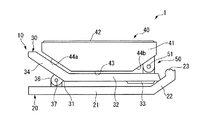
以下、図面を参照して、本発明の音楽用電子機器の実施形態としての調律装置について説明する。図1は実施形態に係る調律装置の側面図、図2は調律装置をクリップ部によって楽器に取り付けた場合の側面図、図3は実施形態に係る調律装置の平面図である。
図1から図3に示すように、調律装置1は、クリップ部10と、調律装置本体40とを有している。
Hereinafter, a tuning device as an embodiment of a music electronic device of the present invention will be described with reference to the drawings. 1 is a side view of a tuning device according to the embodiment, FIG. 2 is a side view of the tuning device attached to a musical instrument by a clip portion, and FIG. 3 is a plan view of the tuning device according to the embodiment.
As shown in FIGS. 1 to 3, the
クリップ部10は、互いに対をなす第1板材20及び第2板材30の間に配置され、ねじりコイルバネや板バネ(図示省略)を備えたヒンジ部36の付勢力によって、例えば管楽器やギター等の楽器を挟持することにより、調律装置1を該楽器に取り付けるものである。
The
図1に示すように、第1板材20は、矩形平板形状をなす第1板材本体21を有しており、該第1板材本体21の長手方向の先端側(図1における右側)には、該第1板材本体21の先端から上方に向かって傾斜して延在する顎板部22が一体に形成されている。この顎板部22の先端部上面には縦断面視半球状をなす下パッド23が突設されている。
As shown in FIG. 1, the
第2板材30は、上記第1板材20の上方に対向配置され、矩形平板がその中間部において下方に凸となるように屈折した形状をなしている。
この屈折部31を境界とした第2板材30の先端側の部分は、上記第1板材20と平行に延びる挟持板部32とされており、該挟持板部32の先端部下面には、シート状をなす上パッド33が敷設されている。
また、屈折部31を境界とした後端側の部分は、屈折部31から後端側に向かうに従って第1板材20から逃げるように傾斜して延びる逃げ板部34とされている。
The
A portion on the front end side of the
Further, the rear end portion with the refracting
そして、逃げ板部34の先端部下面と第1板材20の上面における逃げ板部34の先端部下面に対向する箇所とが、ヒンジ部36によって連結されている。
Then, the lower surface of the distal end portion of the
このヒンジ部36は、第1板材20及び第2板材30の長手方向に直交するとともにこれら第1板材20及び第2板材30の板面に平行な回転軸37を有しており、これによって、第1板材20及と第2板材30とが対向状態を維持しつつ該回転軸37を支点として互いに相対回動するようになっている。
The
このヒンジ部36は、図示しないバネ等の弾性部材によって第1板材20と挟持板部32とを接近させる方向に回動付勢している。これにより、第1板材20と第2板材30の挟持板部32とが近接してクリップ部10が閉じた状態とされ、この際、第2板材30の先端が第1板材20の顎板部22の上面に当接して、第2板材30の挟持板部32と第1板材20とが平行状態に維持される。
また、第2板材30の逃げ板部34の後端側と第1板材20の後端側とを接近させる方向に外力を加えると、挟持板部32と第1板材先端部上面とが離間し、クリップ部10が開いて楽器を把持可能な状態となる。
The
Further, when an external force is applied in a direction in which the rear end side of the
このようなクリップ部10の第2板材30の上方には、挟持板部32の上面と逃げ板部34の上面とに囲われた空間が形成され、該空間が調律装置1の調律装置本体40の収納スペースとされている。
A space surrounded by the upper surface of the
調律装置本体40は、図1及び図2に示すように概略船形状をなし樹脂製からなる筐体41を備えており、該筐体41における平坦状の表面全域には、セント表示が表示される表示面42が設けられている。この表示面42の詳細については後述する。
As shown in FIGS. 1 and 2, the tuning device
上記筐体41の内部には、電気回路や電池とともに振動センサ(図示省略)が内蔵されている。楽器の演奏時には空気を伝搬する振動、あるいは直接的に楽器に接触するクリップ部10を介して伝搬する振動が振動センサによって検知され、この振動の検知に基づく電気信号が増幅回路により所望のレベルの電気信号に増幅されてピッチ抽出手段に入力される。このピッチ抽出手段は、例えば「入力された信号の中で最も周期が長い基本波成分の周期を計測する」というような命令が記憶されているメモリとマイクロコンピュータで実現される。これによって、楽器の音の基本周波数が抽出される。
続いて、このピッチ抽出手段において計測された基本周波数と予め設定されている基準周波数がピッチ誤差検出手段に入力される。このピッチ誤差検出手段は「入力された周波数の偏差を計算する」という命令が記憶されているメモリとマイクロコンピュータによって実現される。
そして、このピッチ誤差検出手段において計算された周波数偏の偏差の値に応じて、表示面42に結果が表示される。
A vibration sensor (not shown) is built in the
Subsequently, the fundamental frequency measured by the pitch extracting means and a preset reference frequency are input to the pitch error detecting means. This pitch error detecting means is realized by a memory and a microcomputer in which an instruction “calculate the deviation of the input frequency” is stored.
Then, the result is displayed on the
また、上記筐体41は、表示面42の反対側に位置し該表示面42と平行をなす主背面43と、該主背面43の長手方向両端側から広がるようにそれぞれ前面側に傾斜して延びる一対の傾斜背面44a、44bとを有している。
この傾斜背面44a、44bのうち、一方の傾斜背面44aと主背面43とのなす角度は、上記第2板材30の挟持板部32と逃げ板部34とのなす角度と同一に形成されている。
The
Of the inclined back surfaces 44a and 44b, the angle formed by one
そして、本実施形態においては、上記構成の調律装置本体40が、表示面42を上方に向けるとともに、主背面43を第2板材30の挟持板部32上に沿わせ、さらに、一方の傾斜背面44aを第2板材30の逃げ板部34に沿わせた収納状態で、第2板材30上に配置される。
そして収納状態において、第2板材30の挟持板部32の先端部上面と、調律装置本体40の筐体41の他方の傾斜背面44bとが連結部材50によって連結支持されている。
In the present embodiment, the tuning device
In the housed state, the upper surface of the distal end portion of the
該連結部材50は、第2板材30及び調律装置本体40の長手方向に直交するとともにこれら第2板材30の上面及び調律装置本体40の表示面42に平行な回転軸51を有している。この回転軸51を支点として第2板材30と調律装置本体40とが相対回動可能に構成されている。これによって、調律装置本体40は、図1に示すようにその背面が第2板材30の上面に沿って配置される収納状態と、図2に示すように表示面42が第1板材20及び第2板材30の先端側、即ち、クリップ部10の先端側を向く立ち上がり状態との間で回動可能とされている。
なお、本実施形態の調律装置1においては、調律装置本体40が、上記回転軸51回りに収納状態と立ち上がり状態との間で回動可能とされる他、該回転軸51と直交し第2板材30に対して垂直な他の回転軸(図示省略)回りに回動可能とされている。これによって表示面42の向きを任意に変更することができるようになっている。
The connecting
In the
以上のような構成の調律装置1は、未使用時においては通常調律装置本体40が収納状態とされており、使用する際にはクリップ部10の第1板材20と挟持板部32とによって楽器を挟み込み、調律装置本体40を立ち上がり状態へと回動させる。
その後、楽器が演奏されると、その振動周波数が調律装置本体40に内蔵された振動センサによって検知され、楽器の音の基本周波数と比較の基準となる基準周波数との偏差を測定し、その偏差がセント表示として表示面42に表示される。
When the
Thereafter, when the musical instrument is played, the vibration frequency is detected by a vibration sensor built in the tuning device
次に、この表示面42のセント表示について説明する。なお、図3及び図4における矢印は表示面42の上下方向Aを示しおり、調律装置1は表示面42の短手方向を上下方向Aに沿わせた状態で設置されているものとする。
Next, the cent display on the
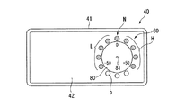
表示面42には、詳しくは図4に示すように、環状表示部60が備えられている。環状表示部60は、例えばLEDからなる発光体P(P1〜P12)が円周上に複数(本実施形態では12個)等間隔を空けて配置されることで構成されている。この発光体Pはそれぞれ例えば3色以上の異なる色彩に発光可能な多色LEDから構成されている。
As shown in detail in FIG. 4, the
これら発光体Pのうち、一の発光体P1、即ち、表示面42の上下方向Aに対する円周上の位置関係が最上位置となる発光体P1が、楽器の音の基本周波数と予め設定された基準周波数との偏差が0を示す調律基準位置Nとされている。この調律基準位置Nにおいては発光体P1は第1の色彩である基準色に発光する。
また、調律基準位置Nの発光体P1の一方側、即ち、反時計回り方向側の複数(本実施形態では4つ)の発光体P9〜P12は、基準周波数に比べて楽器の音の基本周波数が小さく偏差が−となる低表示域Lとされている。この低表示域Lにおいて発光体P9〜P12は基準色と異なる第2の色彩である低域色に発光する。
さらに、調律基準位置Nの発光体P1の他方側、即ち、時計回り方向側の複数(本実施形態では4つ)の発光体P2〜P5は、基準周波数に比べて楽器の音の基本周波数が高く偏差がプラスとなる高表示域Hとされている。この高表示域Hにおいて発光体P2〜P5は、基準色及び低域色と異なる第3の色彩である高域色に発光する。
Among these illuminants P, one illuminant P1, that is, the illuminant P1 whose positional relationship on the circumference with respect to the vertical direction A of the
Further, a plurality of (four in this embodiment) light emitters P9 to P12 on the one side of the tuning reference position N, that is, the counterclockwise direction side, have a fundamental frequency of the sound of the musical instrument compared to the reference frequency. Is a low display area L with a small deviation. In the low display area L, the light emitters P9 to P12 emit light in a low color, which is a second color different from the reference color.
Further, the other side of the light emitter P1 at the tuning reference position N, that is, a plurality of (four in the present embodiment) light emitters P2 to P5 has a fundamental frequency of the sound of the instrument compared to the reference frequency. A high display area H in which the deviation is positive is high. In the high display area H, the light emitters P2 to P5 emit light in the high color, which is a third color different from the reference color and the low color.
そして、これら調律基準位置N、低表示位置L及び高表示域Hの発光体Pは、楽器の音が入力されない待機状態においては輝度を抑えた半点灯状態とされており、楽器の音が入力された際には、該音の基本周波数と予め定めた基準周波数との偏差に対応する位置の発光体Pが点灯してセント表示を行う。これにより、演奏者が調律状態を視覚的に認識することができるようになっている。なお、図3及び図4においては、低表示域Lの発光体P11が調律状態を示すものとして点灯しており、これは楽器の音の基本周波数が基準周波数に比べて小さいことを示している。 The illuminators P at the tuning reference position N, the low display position L, and the high display area H are in a semi-lighted state with reduced brightness in a standby state where the sound of the instrument is not input, and the sound of the instrument is input. When the light is emitted, the light emitter P at a position corresponding to the deviation between the fundamental frequency of the sound and a predetermined reference frequency is turned on to display the cent. As a result, the performer can visually recognize the tuning state. In FIGS. 3 and 4, the illuminant P11 in the low display area L is lit to indicate the tuning state, which indicates that the fundamental frequency of the sound of the instrument is lower than the reference frequency. .
本実施形態の調律装置1において上記の環状表示部60は、表示面42の上下の変化によって調律基準位置Nとなる発光体Pが他の発光体Pに変化し、これに伴って低表示域L及び高表示域Hも変化する。このような変化は、液晶部42の上下を認識する上下認識手段70の出力に基づいて実行される。
In the
上下認識手段70の一例としては、図5に示す振り子機構71を挙げることができる。この振り子機構71は、環状表示部60の中心を軸線とした回転軸72を備えており、この回転軸72は調律装置本体40に対して相対回転可能とされている。また、回転軸72には、その径方向外側に向かって直線状に延びる振り子棒73が固定されており、該振り子棒73の先端には所定の重量を備えたウエイトWが設けられている。このような構成とすることにより、図6(a)〜(c)に示すように、表示面42の上下が変化した場合であっても常にウエイトWが最下方に位置するように回転軸72が回転し、上下方向Aを認識できるようになっている。
As an example of the vertical recognition means 70, a
そして、上下認識手段70が認識した上下方向Aの情報に基づいて、図6(a)〜(c)に対応する図7(a)〜(c)に示すように、調律基準位置N、低表示域L及び高表示域Hとされる発光体Pが変化する。
即ち、本実施形態においては、表示面42の上下に関わらず、上下方向Aに対する円周上の位置関係が最上位置にある発光体Pが常に調律基準位置Nとされ、その両側がそれぞれ低表示域L、高い表示域Hとされるのである。そして、調律基準位置Nにある発光体Pは常に基準色で発光し、低表示域Lにおいては低域色に、高表示域Hにおいては高域色でそれぞれ発光する。
Then, based on the information in the vertical direction A recognized by the vertical recognition means 70, as shown in FIGS. 7A to 7C corresponding to FIGS. The illuminant P, which is the display area L and the high display area H, changes.
That is, in the present embodiment, regardless of whether the
以上のような表示面42を備えた調律装置1においては、環状表示部60の上下が変化した場合に上下認識手段70が上下を認識してこの出力に基づいて調律基準位置Nとなる発光体Pが変化するため、環状表示部60の上下方向が変化しても、演奏者が違和感なく調律状態を認識することができる。
In the
より具体的には、環状表示部60の上下にかかわらず、上下方向Aに対する円周上の位置関係が最上位置にある発光体Pが常に調律基準位置Nとされ、その両側に低表示域L、高表示域Hが配置されるため、表示面42の上下が変化した場合であっても、演奏者から見て常に同一位置に同様のセント表示を表示することができる。よって、調律装置1の楽器への取り付け位置や表示面42の向きにかかわらず、演奏者が違和感なく調律状態を認識することが可能となる。
特に、表示面42の上下が反転した場合のみならず、該表示面42が斜め(図6(a)、図7(a)参照)や縦(図6(b)、図7(b)参照)においても同一位置にセント表示を表示することができるため、楽器の取り付け位置等の制約を受けずに、演奏者が違和感なく調律状態を認識することができる。
More specifically, regardless of the upper and lower sides of the
In particular, not only when the
また、本実施形態においては、上下方向Aに対する円周上において、最上位置となる発光体Pが調律基準位置Nとされるため、演奏者が感覚的に調律基準位置Nを容易に把握することができる。したがって、より違和感なく調律状態を認識することが可能となる。 Further, in the present embodiment, since the light emitter P which is the uppermost position on the circumference with respect to the vertical direction A is set as the tuning reference position N, the player can easily grasp the tuning reference position N sensuously. Can do. Therefore, it is possible to recognize the tuning state without a sense of incongruity.
さらに、調律基準位置N、低表示域L及び高表示域Hの各発光体Pは、楽器の音が入力されない待機状態においては輝度を抑えて点灯させた半点灯状態とされているため、待機状態においてセント表示の取り得る範囲を示すことができる。したがって、調律時に楽器の基本周波数を容易に認識することが可能となる。 Furthermore, each of the light emitters P in the tuning reference position N, the low display area L, and the high display area H is in a semi-lighted state in which the brightness is reduced in a standby state in which no instrument sound is input. The range in which the cent display can be taken in the state can be shown. Therefore, it becomes possible to easily recognize the fundamental frequency of the musical instrument during tuning.
さらにまた、低表示域Lの発光体Pと高表示域Hの前記発光体Pとが互いに異なる色彩に発光するため、調律基準位置Nから見て一方側が低表示域L、他方側が高表示域Hといったように方向によって楽器の基本周波数を認識するのに加えて、色彩の違いによって高低を認識することができるため、楽器の基本周波数の認識をより容易に行うことができる。 Furthermore, since the illuminant P in the low display area L and the illuminant P in the high display area H emit light in different colors, when viewed from the tuning reference position N, one side is the low display area L and the other side is the high display area. In addition to recognizing the fundamental frequency of the musical instrument depending on the direction, such as H, it is possible to recognize the height based on the difference in color, so that the fundamental frequency of the musical instrument can be recognized more easily.
以上、本発明の実施の形態である調律装置1について詳細に説明したが、本発明の技術的思想を逸脱しない限り、これらに限定されることはなく、多少の設計変更等も可能である。
As described above, the
例えば、調律装置1としては、調律装置本体1が上記クリップ部40によって楽器に取り付けられる構成としたが、上記クリップ部40の構造はいかなるものであってもよく、また、クリップ部40が設けられていないものであってもよい。
また、上下方向Aに対する円周上の位置関係が最上位置となる発光体Pを調律基準位置Nとしたが、これに代えて、上下方向Aに対する円周上の位置関係が最下位置となる発光体Pを調律基準位置Nとしてもよい。
さらに、最上位置、最下位置の他、上下方向Aに対する円周上の位置関係が所定位置、例えば中間位置、斜め位置等の発光体Pを調律基準位置Nとしたものであってもよい。
For example, the
Further, the light emitter P having the highest positional relationship on the circumference with respect to the vertical direction A is defined as the tuning reference position N. Instead, the positional relationship on the circumference with respect to the vertical direction A is the lowest position. The light emitter P may be set as the tuning reference position N.
Further, in addition to the uppermost position and the lowermost position, the illuminant P having a predetermined positional relationship in the circumference with respect to the vertical direction A, such as an intermediate position or an oblique position, may be the tuning reference position N.
また、実施形態においては、低表示域L及び高表示域Hの発光体Pの発光色を単に異なるものとしたが、これに代えて、低表示域L及び高表示域Hの発光体Pの発光色の濃淡が一方側から他方側に向かうに従って、即ち時計回り方向に向かうに従って、連続的に変化するように構成してもよい。この場合、発光体Pとして、発光色の濃淡の段階数に応じた数の色彩を発光可能な多色LEDを用いる必要がある。
このように構成することによって、調律基本位置Nから見て一方側が低表示域、他方側が高表示域といったように方向によって楽器の基本周波数を認識するのに加えて、色彩の濃淡よって高低を認識することができるため、楽器の基本周波数の認識をより容易に行うことができる。
In the embodiment, the light emission colors of the light emitting elements P in the low display area L and the high display area H are simply different from each other. You may comprise so that the shading of luminescent color may change continuously as it goes to the other side from one side, ie, it goes to the clockwise direction. In this case, it is necessary to use a multicolor LED capable of emitting a number of colors corresponding to the number of steps of the light emission color as the light emitter P.
By configuring in this way, in addition to recognizing the fundamental frequency of the instrument depending on the direction, such as the low display area on one side and the high display area on the other side when viewed from the tuning basic position N, the high and low are recognized by the shade of the color. Therefore, the fundamental frequency of the musical instrument can be recognized more easily.
また、例えば図8に示すように、調律基準位置Nの発光体Pを指し示すマーク(例えば「0」)が記載された表示パネル80が設けられていてもよい。なお、表示パネル80にはセント表示の高低を示す数値が記載されていてもよい。
For example, as shown in FIG. 8, a
この表示パネル80は、図8及び図9に示すように、直径が環状表示部60の内径と略同一の円板状をなしており、該環状表示部60と中心を一致させた状態で中心回りに回転可能に取り付けられている。即ち、この表示パネル80は、調律装置本体40に内蔵され環状表示部60の中心を軸線とした回転軸81の一端側に固定されており、該回転軸81が調律装置本体40に対して相対回転することによって、表示面42上で回転する。また回転軸81には、その径方向外側に向かって直線上に延びる振り子棒82が固定されており、先端には所定の重量を備えたウエイトWが設けられている。
As shown in FIGS. 8 and 9, the
このような構成とすることにより、表示面42の上下が変化した場合には常にウエイトWが最下方に位置するように回転軸81及び表示パネル80が回転する。これによって、表示パネル80のマークは、上下方向Aに対する位置関係が常に同一の箇所に位置し、例えば、上下方向Aに対する円周上の位置関係における最上位置の発光体Pを指し示すこととなる。
With such a configuration, the rotating
したがって、上下認識手段70の上下認識に基づいて調律基準位置Nとなる発光体Pが変化した場合であっても、表示パネル80が当該変化に追従して回転し、該表示パネル80のマークでもって常に調律基準位置Nの発光体Pを指し示すことができる。これにより、演奏者が調律基準位置Nを容易に把握して、違和感なく調律作業を行うことができる。
なお、表示パネル80が取り付けられた回転軸81、振り子棒82、ウエイトWが、上下認識手段70としての振り子機構71を兼ねた構成であってもよい。
Accordingly, even when the light emitter P that is the tuning reference position N changes based on the vertical recognition of the vertical recognition means 70, the
Note that the
さらに、例えば図10に示すように、低表示域L及び高表示域Hの各発光体Pに対応する箇所にそれぞれ貫通孔91を有する孔空きパネル90が設けられていてもよい。
この孔空きパネル90は、図10及び図11に示すように、直径が環状表示部60の外径よりも大きな円板状をなしており、該環状表示部60と中心を一致させた状態で該中心回りに回転可能に取り付けられている。即ち、この孔空きパネル90は、調律装置本体40に内蔵され環状表示部60の中心を軸線とした回転軸92の一端側に固定されており、該回転軸92が調律装置本体40に対して相対回転することによって、表示面42上で回転する。また回転軸81には、その径方向外側に向かって直線上に延びる振り子棒93が固定されており、先端には所定の重量を備えたウエイトWが設けられている。
また、低表示域L及び高表示域Hの発光体Pに対応する貫通孔91は、その直径が、一方側から他方側に向かうに従って、即ち、時計回り方向に向かうにしたがって、段階的に大きくなるように形成されている。なお、調律基準位置Nに対応する箇所にも貫通孔95が設けられてあってもよい。
Further, for example, as shown in FIG. 10,
As shown in FIGS. 10 and 11, the
Further, according to the through-
このような構成とすることにより、表示面42の上下が変化した場合には、ウエイトWが最下方に位置するように回転軸92及び孔空きパネル90が回転する。これによって、各貫通孔91、95は上下方向Aに対する位置関係が同一の箇所に維持され、常に、調律基準位置N、低表示域L及び高表示域Hの発光体P上に位置することになる。
このようにして、表示面42の上下の変化に伴って調律基準位置Nが変化した場合であっても、孔空きパネル90が追従するように回転し、大小の貫通孔でもって楽器の基本周波数の高低を示すことができる。
また、このように貫通孔91、95の大きさでもって調律基準位置N、低表示域L及び高表示域Hが認識できれば、発光体Pを単色LEDで構成しても、演奏者が調律状態を違和感なく認識することができるといったメリットがある。
なお、孔空きパネル90が取り付けられた回転軸92、振り子棒93、ウエイトWが、上下認識手段70としての振り子機構71を兼ねた構成であってもよく、さらに、孔空きパネル90にマークが記載されて上記表示パネル80の機能を兼ねたものであってもよい。
With this configuration, when the top and bottom of the
In this way, even if the tuning reference position N changes with the vertical change of the
Further, if the tuning reference position N, the low display area L, and the high display area H can be recognized by the size of the through
The rotating
さらにまた、実施形態においては、振り子機構71を用いた上下認識手段70について説明したが、これに代えて、例えば図12に示すように、上下認識手段70が、各発光体P近傍にそれぞれ設けられた上下認識スイッチ75を備えたものであってもよい。
、このような構成の場合、調律装置本体40の上下の向きに応じて、演奏者自信が最上位置にある発光体Pの近傍の上下認識スイッチ75を押すと、この上下認識スイッチ75近傍の発光体Pが調律基準位置Nとされる。即ち、表示面42の上下がどのような向きになろうとも、演奏者の手動でもって調律基準位置Nを最上位置や最下位置、もしくは任意の位置に設定することができるのである。これによって、表示面42の上下が変化した場合であっても、演奏者が違和感なく調律状態を認識することができる。
Furthermore, in the embodiment, the vertical recognition means 70 using the
In the case of such a configuration, when the up / down
また、上下認識手段70として、加速度センサーを採用してもよい。この場合、表示面42の上下が変化する際の加速度を検知することで、該表示面42の上下方向を認識することが可能となる。また、小型の加速度センサーを用いれば、上記振り子機構71を用いた場合に比べて、構成自体のコンパクト化を図ることが可能となる。
Further, an acceleration sensor may be employed as the vertical recognition means 70. In this case, it is possible to recognize the vertical direction of the
1 調律装置
10 クリップ部
20 第1板材
21 第1板材本体
22 顎板部
23 下パッド
30 第2板材
31 屈折部
32 挟持板部
33 上パッド
34 逃げ板部
36 ヒンジ部
37 回転軸
40 調律装置本体
41 筐体
42 表示面
43 主背面
44a 傾斜背面
44b 傾斜背面
50 連結部材
51 回転軸
60 環状表示部
70 上下認識手段
71 振り子機構
72 回転軸
73 振り子棒
75 上下認識スイッチ
80 表示パネル
81 回転軸
82 振り子棒
90 孔空きパネル
91 貫通孔
92 回転軸
93 振り子棒
95 貫通孔
A 上下方向
P 発光体
W ウエイト
DESCRIPTION OF
Claims (9)
複数の発光体が円周上に配置されてなる環状表示部を備え、
前記発光体のうち、一の前記発光体が前記偏差0の調律基準位置とされ、前記調律基準位置の一方側の複数の前記発光体が前記偏差が−となる低表示域とされるとともに前記調律基準位置の他方側の複数の前記発光体が前記偏差が+となる高表示域とされ、
前記環状表示部の上下を認識する上下認識手段を備え、
前記環状表示部の上下が変化した場合に、前記上下認識手段の出力に基づいて、前記調律基準位置とされる前記発光体が変化し、
上下方向に対する前記円周上の位置関係が所定位置となる一の前記発光体が調律基準位置とされ、
前記環状表示部の上下が変化した場合に、前記上下認識手段の出力に基づいて、新たに前記所定位置となった前記発光体が前記調律基準位置とされることを特徴とする調律装置。 In the tuning device that measures the deviation between the fundamental frequency of the sound of the instrument and the reference frequency that is the reference for comparison, and displays the deviation as a cent display,
Provided with an annular display portion in which a plurality of light emitters are arranged on the circumference,
Among the light emitters, one of the light emitters is set as a tuning reference position with a deviation of 0, and the plurality of light emitters on one side of the tuning reference position are set as a low display area where the deviation is − and The plurality of light emitters on the other side of the tuning reference position is a high display area in which the deviation is +,
Comprising a vertical recognition means for recognizing the top and bottom of the annular display part;
When the upper and lower of the annular display portion is changed, based on the output of the upper and lower recognizing means, the light emitter that is the tuning reference position is changed ,
One of the light emitters whose positional relationship on the circumference with respect to the vertical direction is a predetermined position is set as a tuning reference position,
The tuning apparatus according to claim 1, wherein, when the upper and lower sides of the annular display portion are changed, the light emitting body that has newly become the predetermined position is set as the tuning reference position based on the output of the vertical recognition means .
該表示パネルが前記調律基準位置の変化に追従して回転するように構成されていることを特徴とする請求項1から5のいずれか一項に記載の調律装置。 A display panel that is rotatably mounted around the center axis of the annular display portion and includes a mark that indicates the tuning reference position,
Tuning device according to any one of claims 1 to 5, characterized in that the display panel is configured to rotate to follow the change in the rhythm reference position.
前記貫通孔の直径が前記一方側から前記他方側に向かうに従って漸次大きくなるように形成され、
前記孔空きパネルが前記調律基準位置に追従して回転するように構成されていることを特徴とする請求項1から5のいずれか一項に記載の調律装置。 It is rotatably attached around the center axis of the annular display portion, and includes a perforated panel having through holes at locations corresponding to the light emitters of the low display area and the high display area, respectively.
Is formed to become gradually larger as the diameter of the through hole toward the other side in the said one side,
Tuning device according to any one of claims 1 to 5, characterized in that the perforated panel is configured to rotate to follow the rhythm reference position.
Priority Applications (1)
| Application Number | Priority Date | Filing Date | Title |
|---|---|---|---|
| JP2009027423A JP5288552B2 (en) | 2009-02-09 | 2009-02-09 | Tuning device |
Applications Claiming Priority (1)
| Application Number | Priority Date | Filing Date | Title |
|---|---|---|---|
| JP2009027423A JP5288552B2 (en) | 2009-02-09 | 2009-02-09 | Tuning device |
Publications (2)
| Publication Number | Publication Date |
|---|---|
| JP2010181798A JP2010181798A (en) | 2010-08-19 |
| JP5288552B2 true JP5288552B2 (en) | 2013-09-11 |
Family
ID=42763392
Family Applications (1)
| Application Number | Title | Priority Date | Filing Date |
|---|---|---|---|
| JP2009027423A Expired - Fee Related JP5288552B2 (en) | 2009-02-09 | 2009-02-09 | Tuning device |
Country Status (1)
| Country | Link |
|---|---|
| JP (1) | JP5288552B2 (en) |
Families Citing this family (4)
| Publication number | Priority date | Publication date | Assignee | Title |
|---|---|---|---|---|
| JP2012141358A (en) * | 2010-12-28 | 2012-07-26 | Korg Inc | Tuner with clip |
| JP7328634B2 (en) * | 2018-12-05 | 2023-08-17 | 後藤ガット有限会社 | musical instrument tuner |
| JP7307906B2 (en) | 2019-02-01 | 2023-07-13 | 後藤ガット有限会社 | musical instrument tuner |
| JP7307422B2 (en) | 2019-02-01 | 2023-07-12 | 銀河ソフトウェア株式会社 | Performance support system, method and program |
Family Cites Families (3)
| Publication number | Priority date | Publication date | Assignee | Title |
|---|---|---|---|---|
| US7049502B2 (en) * | 2003-10-24 | 2006-05-23 | Korg, Inc | Music tuner |
| JP2006068027A (en) * | 2004-08-31 | 2006-03-16 | Nintendo Co Ltd | Game device and game program |
| JP2008170769A (en) * | 2007-01-12 | 2008-07-24 | Korg Inc | Tuner |
-
2009
- 2009-02-09 JP JP2009027423A patent/JP5288552B2/en not_active Expired - Fee Related
Also Published As
| Publication number | Publication date |
|---|---|
| JP2010181798A (en) | 2010-08-19 |
Similar Documents
| Publication | Publication Date | Title |
|---|---|---|
| CA2358526C (en) | Electronic stringed musical instrument | |
| US8785758B2 (en) | Electronic hi-hat cymbal controller | |
| US20120036982A1 (en) | Digital and Analog Output Systems for Stringed Instruments | |
| JP5428567B2 (en) | Electronic percussion instrument | |
| US8907190B2 (en) | Switch device and electronic musical instrument | |
| JP5288552B2 (en) | Tuning device | |
| CN107438880A (en) | Electronic percussion instrument | |
| JP2007256979A (en) | Electronic percussion instrument | |
| JP4385953B2 (en) | Electric stringed instruments | |
| CN117321676A (en) | Detection system for musical instruments and musical instruments | |
| KR20130074435A (en) | Portable trainer for playing the guitar | |
| CN219696074U (en) | Digital guitar | |
| JP4247272B2 (en) | Electronic hi-hat cymbal | |
| WO2002080137A1 (en) | Built-in type tuning module for stringed instrument | |
| JP5288549B2 (en) | Music electronics | |
| US20080229906A1 (en) | Electric stringed music instrument with music tuner | |
| JP2017116680A (en) | Support device for training or recording of string musical instrument | |
| JP7636034B2 (en) | Operation input device and electronic musical instrument | |
| US20230057338A1 (en) | Chordophone with speaker function | |
| CN202996263U (en) | Tuners for stringed instruments | |
| KR102958648B1 (en) | Electronic drum with lighting pad | |
| CN219936668U (en) | Pedal drum-beating device | |
| KR102959286B1 (en) | Electronic drum to provide user interface for playing drum | |
| KR20250060343A (en) | Electronic drum with lighting pad | |
| CN223333521U (en) | Electronic drum |
Legal Events
| Date | Code | Title | Description |
|---|---|---|---|
| A621 | Written request for application examination |
Free format text: JAPANESE INTERMEDIATE CODE: A621 Effective date: 20111206 |
|
| A977 | Report on retrieval |
Free format text: JAPANESE INTERMEDIATE CODE: A971007 Effective date: 20130215 |
|
| A131 | Notification of reasons for refusal |
Free format text: JAPANESE INTERMEDIATE CODE: A131 Effective date: 20130219 |
|
| A521 | Written amendment |
Free format text: JAPANESE INTERMEDIATE CODE: A523 Effective date: 20130419 |
|
| A01 | Written decision to grant a patent or to grant a registration (utility model) |
Free format text: JAPANESE INTERMEDIATE CODE: A01 Effective date: 20130521 |
|
| RD03 | Notification of appointment of power of attorney |
Free format text: JAPANESE INTERMEDIATE CODE: A7423 Effective date: 20130531 |
|
| A61 | First payment of annual fees (during grant procedure) |
Free format text: JAPANESE INTERMEDIATE CODE: A61 Effective date: 20130531 |
|
| LAPS | Cancellation because of no payment of annual fees |