JP5286741B2 - Fuel cell system - Google Patents
Fuel cell system Download PDFInfo
- Publication number
- JP5286741B2 JP5286741B2 JP2007274894A JP2007274894A JP5286741B2 JP 5286741 B2 JP5286741 B2 JP 5286741B2 JP 2007274894 A JP2007274894 A JP 2007274894A JP 2007274894 A JP2007274894 A JP 2007274894A JP 5286741 B2 JP5286741 B2 JP 5286741B2
- Authority
- JP
- Japan
- Prior art keywords
- fuel cell
- pure water
- flow path
- detected
- fuel
- Prior art date
- Legal status (The legal status is an assumption and is not a legal conclusion. Google has not performed a legal analysis and makes no representation as to the accuracy of the status listed.)
- Expired - Fee Related
Links
Images


Classifications
-
- Y—GENERAL TAGGING OF NEW TECHNOLOGICAL DEVELOPMENTS; GENERAL TAGGING OF CROSS-SECTIONAL TECHNOLOGIES SPANNING OVER SEVERAL SECTIONS OF THE IPC; TECHNICAL SUBJECTS COVERED BY FORMER USPC CROSS-REFERENCE ART COLLECTIONS [XRACs] AND DIGESTS
- Y02—TECHNOLOGIES OR APPLICATIONS FOR MITIGATION OR ADAPTATION AGAINST CLIMATE CHANGE
- Y02E—REDUCTION OF GREENHOUSE GAS [GHG] EMISSIONS, RELATED TO ENERGY GENERATION, TRANSMISSION OR DISTRIBUTION
- Y02E60/00—Enabling technologies; Technologies with a potential or indirect contribution to GHG emissions mitigation
- Y02E60/30—Hydrogen technology
- Y02E60/50—Fuel cells
Description
本発明は、多孔質セパレータを介して反応ガスを加湿し、かつ気化潜熱でシステムを冷却する純水が流通する流通路を備えた燃料電池システムに関する。 The present invention relates to a fuel cell system provided with a flow passage through which pure water for humidifying a reaction gas through a porous separator and cooling the system with latent heat of vaporization flows.
一般に固体高分子型燃料電池では、使用されている固体高分子電解質膜の湿潤状態によっては、イオン導電性を十分に発揮できないものがあるので、燃料ガスや酸化剤ガスを加湿することにより固体高分子電解質膜の湿潤状態を保持している。 Generally, in some polymer electrolyte fuel cells, depending on the wet state of the solid polymer electrolyte membrane used, there are those that do not exhibit sufficient ionic conductivity. Therefore, solid fuel can be obtained by humidifying fuel gas or oxidant gas. The wet state of the molecular electrolyte membrane is maintained.
燃料ガスや酸化剤ガスの加湿方法には、燃料電池スタックの外部に設けた加湿器により加湿する外部加湿方式と、燃料電池スタックの内部で加湿する内部加湿方式とがある。 There are two types of humidification methods for fuel gas and oxidant gas: an external humidification method in which humidification is performed by a humidifier provided outside the fuel cell stack, and an internal humidification method in which humidification is performed inside the fuel cell stack.
内部加湿方式では、水分を染み込ませることができる多孔質セパレータ(ポーラスタイプのセパレータ)を用い、これら多孔質セパレータに純水などを供給し、多孔質セパレータに染み込んだ水分と燃料ガスや酸化剤ガスとを接触させることで燃料ガスや酸化剤ガスの少なくとも一方の反応ガスを加湿している。また、内部加湿方式の中には、多孔質セパレータに染み込んだ水分の蒸発に伴う気化潜熱によって燃料電池を冷却する燃料電池システムがある。 In the internal humidification method, porous separators (porous separators) that can soak moisture are used, pure water is supplied to these porous separators, and moisture soaked in porous separators, fuel gas, and oxidant gas Are in contact with each other to humidify at least one reaction gas of the fuel gas and the oxidant gas. Further, in the internal humidification system, there is a fuel cell system that cools the fuel cell by latent heat of vaporization accompanying evaporation of moisture soaked in a porous separator.
このような多孔質セパレータを備えた従来の燃料電池としては、例えば以下に示す特許文献1、特許文献2に記載されたものが知られている。
上記従来の燃料電池で採用されている多孔質セパレータは、水分で十分に湿潤している場合は反応ガスが透過しにくくなる特徴がある一方で、乾燥時に十分な水分量を含有していない場合には反応ガスが多孔質セパレータを透過してしまう可能性があった。しかし、多孔質セパレータを介して反応ガスが通常経路から漏洩した場合に、これを検知することができないといった不具合があった。 The porous separator employed in the above conventional fuel cell has a feature that the reaction gas is difficult to permeate when sufficiently wetted with moisture, but does not contain a sufficient amount of moisture when dried. In some cases, the reaction gas may permeate the porous separator. However, when the reaction gas leaks from the normal path through the porous separator, there is a problem that this cannot be detected.
そこで、本発明は、上記に鑑みてなされたものであり、その目的とするところは、多孔質セパレータを介した反応ガスの漏洩を検知することができる燃料電池システムを提供することにある。 Therefore, the present invention has been made in view of the above, and an object of the present invention is to provide a fuel cell system capable of detecting leakage of a reactive gas through a porous separator.
上記目的を達成するために、本発明の課題を解決する手段は、燃料ガス供給手段により供給される燃料ガスと、酸化剤ガス供給手段により供給される酸化剤ガスとの電気化学反応により発電を行う燃料電池と、多孔質セパレータを介して前記燃料電池を流通する燃料ガスと酸化剤ガスの少なくともいずれか一方を加湿し、かつ気化により前記燃料電池を潜熱冷却する純水が前記燃料電池内を含んで流通する純水流路を備えた燃料電池システムにおいて、前記多孔質セパレータを介して燃料ガスならびに酸化剤ガスの少なくともいずれか一方が、前記純水流路に漏洩していることを検知する検知手段を備え、前記検知手段は、前記燃料電池の上流側の前記純水流路に設けられた流量検出手段と、前記燃料電池の下流側の前記純水流路を閉塞する閉塞手段を有し、前記燃料電池の下流側の前記純水流路を閉塞し、前記流量検出手段が前記燃料電池の上流側の前記純水流路で純水の逆流を検出した場合に漏洩を検知することを特徴とする。 In order to achieve the above object, a means for solving the problems of the present invention is to generate power by an electrochemical reaction between a fuel gas supplied by a fuel gas supply means and an oxidant gas supplied by an oxidant gas supply means. And pure water that humidifies at least one of the fuel gas and the oxidant gas that circulates through the fuel cell via a porous separator, and that latently cools the fuel cell by vaporization passes through the fuel cell. In a fuel cell system including a pure water flow path that includes and circulates, a detection unit that detects that at least one of a fuel gas and an oxidant gas leaks into the pure water flow path through the porous separator. wherein the sensing means includes flow sensing means upstream of the provided pure water passage of the fuel cell, to close the downstream side the pure water flow path of the fuel cell A blocking means for closing the pure water flow path on the downstream side of the fuel cell, and detecting leakage when the flow rate detecting means detects a reverse flow of pure water in the pure water flow path on the upstream side of the fuel cell; characterized in that it.
本発明によれば、多孔質セパレータを介して燃料ガスならびに酸化剤ガスの少なくともいずれか一方が、純水流路に漏洩していることを検知することができる。 According to the present invention, it is possible to detect that at least one of the fuel gas and the oxidant gas leaks into the pure water flow path through the porous separator.
以下、図面を用いて本発明を実施するための最良の実施例を説明する。 DESCRIPTION OF THE PREFERRED EMBODIMENTS The best embodiment for carrying out the present invention will be described below with reference to the drawings.
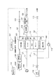
本発明の各実施例1〜9を説明する前に、図1に示す基本構成図ならびに図2の基本動作を示すフローチャートを参照して、各実施例に共通した基本構成ならびに基本動作を説明し、その後各実施例に特徴的な構成ならびに作用を説明する。 Before describing each of the first to ninth embodiments of the present invention, the basic configuration and the basic operation common to each embodiment will be described with reference to the basic configuration diagram shown in FIG. 1 and the flowchart showing the basic operation in FIG. Then, the characteristic configuration and operation of each embodiment will be described.
図1において、各実施例に共通した本発明の燃料電池システムは、燃料ガスと酸化剤ガスとの電気化学反応により発電を行う燃料電池スタック101を備えている。この燃料電池スタック101は、固体高分子電解質膜を含むMEA(Membrane Electrode Assembly:膜電極接合体)102を挟んでアノード極103とカソード極104とが対設され、このアノード極103ならびにカソード極104の外側に多孔質セパレータ(ポーラスセパレータ)105が配置された燃料電池セルの構造体が複数積層(図示せず)されて構成されている。
In FIG. 1, the fuel cell system of the present invention common to each embodiment includes a
このような燃料電池スタック101は、アノード極103側に燃料ガスを供給する燃料ガス流路(図示せず)が設けられ、カソード極104側に酸化剤ガスを供給する酸化剤ガス流路(図示せず)が設けられている。
Such a
なお、以下の説明では燃料ガスおよび酸化剤ガスを総称して反応ガスと呼ぶ。また、以下の実施例においては、燃料電池スタック101が発電反応を発生させるための燃料ガスとして水素ガスをアノード極103に供給し、酸化剤ガスとして酸素を含む空気をカソード極104に供給するものとして説明する。
In the following description, fuel gas and oxidant gas are collectively referred to as reaction gas. In the following embodiments, the
燃料電池スタック101は、固体高分子電解質膜を加湿させる加湿用の純水が供給される多孔質セパレータ105によって、各燃料電池セルを区分している。この多孔質セパレータ105は、一方面が隣接する燃料電池セルの電極側に対向し、各電極に対応した反応ガス流路を形成しており、他方面に加湿用の純水が流通する純水流路106が設けられている。これにより、燃料電池スタック101は、加湿用純水が純水流路106に供給されることにより多孔質セパレータ105の多孔質面が加湿用純水で満たされ、多孔質セパレータ105に染み込んだ加湿用純水によって燃料電池スタック101に供給される反応ガスを加湿し、加湿された反応ガスによって固体高分子電解質膜を加湿している。
The
このような燃料電池システムは、燃料電池スタック101を発電させるに際して、アノード極103に加湿した水素ガスを、カソード極104には加湿した空気を供給し、燃料電池スタック101内の固体高分子電解質膜を加湿し、気化潜熱によって燃料電池スタック101を冷却させる加湿用純水を供給する内部加湿型気化潜熱冷却型の燃料電池システムである。この燃料電池システムは、後述するコントローラ107で運転動作が制御管理されている。
In such a fuel cell system, when generating electricity in the
燃料電池スタック101に供給される空気は、空気供給用ポンプ108で大気を加圧し、例えば空気加湿器(図示せず)にて加湿した後、空気流通配管L1を介して燃料電池スタック101のカソード極104に供給される。このとき、コントローラ107は、空気供給用ポンプ108に接続されたポンプ駆動用のモータ(図示せず)の回転数を制御するとともに、空気排出側の空気流通配管L1に設けられた空気調圧弁109の開度を制御することによりカソード極104に供給する空気流量および空気圧力を調整する。
The air supplied to the
燃料電池スタック101に供給される水素ガスは、水素タンク110に貯蔵された状態から水素調圧弁111、水素流通配管L2を順に介して燃料電池スタック101のアノード極103に供給される。アノード極103から水素排出側の水素流通配管L2に排出された未使用の水素は、通常例えば循環経路に設けられた水素循環ポンプ112によって再度アノード極103側へ循環されて再供給される。
The hydrogen gas supplied to the
また、固体高分子電解質膜を介してカソード極104からアノード極103へ透過した窒素は循環経路に蓄積するため、例えば蓄積された窒素を循環経路外へパージするパージ弁113を備えている。このとき、コントローラ107は水素調圧弁111の開度を制御してアノード極103に供給する水素圧力を調整するととともに、水素循環ポンプ112に接続されたモータの回転数およびパージ弁113の開度を調整する。
Further, in order to accumulate nitrogen that has permeated from the
燃料電池スタック101に供給される加湿用純水は、燃料電池システムの設置環境における高さ方向に対して燃料電池スタック101よりも高い上方に設置されて大気開放された純水タンク114に貯蔵された状態から、純水流通配管L3を介して燃料電池スタック101に供給される。純水流路106の排出側(下流側)の純水流通配管L3には開閉弁115が設けられ、例えば通常運転時には閉弁されて燃料電池スタック101の内部で蒸発した量だけ、純水タンク114から燃料電池スタック101に純水が供給される。
The humidified pure water supplied to the
なお、開閉弁115は、初期状態での純水流通配管L3への水入れやガス抜きの際、ならびに多孔質セパレータ105を介して純水流通配管L3に反応ガスが透過した後の水入れやガス抜きの際に開弁され、通常発電時には閉弁されている。
The on-off
燃料電池スタック101に供給された純水は、多孔質セパレータ105の多孔質面を水分で満たして反応ガスを加湿し、かつ燃料電池スタック101で発生する熱量を気化潜熱によって水蒸気として未反応ガスとともに燃料電池システムの外部へ排出させる。
The pure water supplied to the
さらに、システム外に排出される水蒸気を回収するために、例えば凝縮器116と気液分離器117等から構成される水回収装置を空気流通配管L1における空気調圧弁109の上流側に設け、この装置で回収した純水を純水回収配管L4を介して純水タンク114に送水することで、水収支を成立させることができる。なお、水回収装置から純水タンク114への送水は、例えば純水回収配管L4に設けた純水ポンプ(図示せず)等で行われる。
Further, in order to recover the water vapor discharged outside the system, a water recovery device including, for example, a
上記基本構成では、上述したように純水タンク114から燃料電池スタック101に純水を供給する際にポンプ等の補機類を使用しない構成を採用しているが、純水タンク114と燃料電池スタック101の間の純水流通配管L3に純水供給用のポンプを設け、このポンプにより純水タンク114から燃料電池スタック101に純水を供給する構成を採用してもよい。
In the above basic configuration, as described above, a configuration in which auxiliary equipment such as a pump is not used when pure water is supplied from the
コントローラ107は、本システムの運転を制御する制御中枢として機能し、プログラムに基づいて各種動作処理を制御するコンピュータに必要な、CPU、記憶装置、入出力装置等の資源を備えた例えばマイクロコンピュータ等により実現される。コントローラ107は、後述する各実施例で説明するセンサやこれらのセンサで得られない他の圧力、温度、濃度、電圧、電流等本システムの運転に必要な情報を収集するセンサからの信号を読み込み、読み込んだ各種信号ならびに予め内部に保有する制御ロジック(プログラム)に基づいて、上記各ポンプ、各弁を含む本システムの制御を要する構成要素に指令を送り、以下に説明する多孔質セパレータ105を介した反応ガスの漏洩を検知する動作を含む本システムの運転/停止に必要なすべての動作を統括管理して制御する。
The
また、コントローラ107は、システムの運転時に予め設定された周期で図2のフローチャートに示す処理を繰り返し実行する。すなわち、多孔質セパレータ105を介して反応ガスが純水流路106に漏洩したか否か判別し(ステップS201)、漏洩していると判別された場合には、燃料電池スタック101の発電を停止してシステムの運転を停止する(ステップS202)一連の処理を実行制御する。一方、漏洩していないと判別された場合には、通常運転を継続して処理を終了する。
Further, the
以下に説明する各実施例では、図1に示す構成に対してさらに追加された各実施例に特徴的な構成、ならびに図2のステップS201で示す漏洩判断の手法について説明する。 In each embodiment described below, a characteristic configuration of each embodiment further added to the configuration shown in FIG. 1 and a leak determination technique shown in step S201 of FIG. 2 will be described.
図3は本発明の実施例1に係る燃料電池システムの構成を示す図である。図3に示す実施例1のシステムでは、先の図1に示す基本構成に加えて、燃料電池スタック101と純水タンク114との間の純水流通配管L3に、純水タンク114から燃料電池スタック101に流通する純水の流量を検出する流量センサ301を備えている。
FIG. 3 is a diagram showing the configuration of the fuel cell system according to Embodiment 1 of the present invention. In the system of Embodiment 1 shown in FIG. 3, in addition to the basic configuration shown in FIG. 1, the pure water circulation pipe L3 between the
このような構成において、コントローラ107では、先の図2のステップS201に示す判別処理として、流量センサ301で検出されたセンサ信号を読み込み、このセンサ信号に基づいて純水タンク114から燃料電池スタック101に流通する純水の流量が、予め設定された所定流量以下であるか否かを判別する。ここで、所定流量は、燃料電池スタック101側から純水タンク114側に純水が逆流しているものと推定できる値であり、例えば0L/min以下としてもよいし、もしくは電流負荷(発電量)に応じた流量値を予め実験的に求め、その値に基づいて所定流量値を設定するようにしてもよい。
In such a configuration, the
上記判別の結果、所定流量以下であると判別された場合には、純水が逆流しているものと推定し、多孔質セパレータ105を介して反応ガスが純水流路106に透過して漏洩しているものと判断する。
As a result of the determination, if it is determined that the flow rate is equal to or lower than the predetermined flow rate, it is estimated that pure water is flowing backward, and the reaction gas permeates into the pure
このように、上記実施例1では、通常燃料電池システムに備えられた構成に流量センサ301を加えた簡易な構成で、反応ガスの漏洩を検知することが可能となる。
As described above, in the first embodiment, it is possible to detect the leakage of the reaction gas with a simple configuration in which the
また、反応ガスの漏洩が検知された場合には、燃料電池システムの運転を停止することで、燃費性能や発電性能の低下、また気化潜熱冷却燃料電池システムにおける冷却性能の低下を回避することが可能となり、上記性能の低下した状態で運転を継続した場合に引き起こされるおそれがある燃料電池スタック101の損傷も回避することができる。
In addition, when the leakage of the reaction gas is detected, the operation of the fuel cell system is stopped to avoid the deterioration of the fuel consumption performance and the power generation performance and the cooling performance of the vaporization latent heat cooling fuel cell system. It becomes possible, and damage to the
図4は本発明の実施例2に係る燃料電池システムの構成を示す図である。図4に示す実施例2のシステムでは、先の図3に示す実施例1の構成に加えて、燃料電池スタック101の各セルごとのセル電圧をモニタするセル電圧センサ401を備えている。
FIG. 4 is a diagram showing a configuration of a fuel cell system according to
このような構成において、コントローラ107では、先の図2のステップS201に示す判別処理として、まず流量センサ301ならびにセル電圧センサ401で検出されたセンサ信号を読み込み、流量センサ301で得られた流量が、セル電圧センサ401のセンサ信号に基づいて推定された燃料電池スタック101の純水蒸発量よりも小さいか否かを判別する。判別の結果、小さいと判別された場合には、純水が逆流しているものと推定する。これにより、多孔質セパレータ105を介して反応ガスが純水流路106に透過しているものと推定し、反応ガスの漏洩を検知することができる。
In such a configuration, the
ここで、セル電圧センサ401で得られたセル電圧に基づいて燃料電池スタック101の純水蒸発量を推定する手法について説明する。
Here, a method for estimating the pure water evaporation amount of the
燃料電池スタックにおける電流−電圧特性(I−Vカーブ)は、例えば図5に示すように表される。この特性曲線に基づいて、燃料電池スタックが発電している状態では、燃料電池スタックの発熱量(W)は以下のように表される。 The current-voltage characteristic (IV curve) in the fuel cell stack is expressed as shown in FIG. 5, for example. Based on this characteristic curve, when the fuel cell stack is generating electric power, the heat generation amount (W) of the fuel cell stack is expressed as follows.
(数1)
燃料電池スタックの発熱量=(Vt−V)I
ここで、Vtは理論起電力である。
(Equation 1)
Heat value of fuel cell stack = (Vt−V) I
Here, Vt is a theoretical electromotive force.
一方、燃料電池スタック101の外部放熱を無視した場合に、燃料電池スタック101の発電にともなって発生する発熱量は、燃料電池スタック101に供給される純水の蒸発に使用される。水の相変化、すなわち水が液体から気体に相変化する場合には、以下に示すように熱量が必要となる。
On the other hand, when the external heat dissipation of the
H2O(液体)→H2O(気体)+44000(J/mol)
したがって、燃料電池スタック101の発熱量が燃料電池スタック101に供給された純水の蒸発熱にすべて使用されたものと仮定すると、純水の蒸発量(mol/sec)は、以下のように表される。
H 2 O (liquid) → H 2 O (gas) +44000 (J / mol)
Therefore, assuming that the calorific value of the
(数2)
純水の蒸発量(mol/sec)=燃料電池スタックの発熱量(W)/44000(J/mol)
なお、上記手法では、理解を容易にするために、燃料電池スタック101の発熱量がすべて純水が蒸発する際の熱量に使用されたものとして説明したが、燃料電池スタック101の電圧に対応した純水の蒸発量を予め実験的に求め、その結果をテーブル化してコントローラ107の記憶手段に記憶し、セル電圧センサ401で得られた計測値に基づいて上記テーブルを参照して純水の蒸発量を算出するようにしてもよい。
(Equation 2)
Evaporation amount of pure water (mol / sec) = calorific value of fuel cell stack (W) / 44000 (J / mol)
In the above method, for ease of understanding, it has been described that all the calorific value of the
また、燃料電池スタック101の外部放熱量を考慮できるように、燃料電池スタック101の表面の温度ならびに大気の温度を計測し、両温度差から推定される外部放熱量で純水の蒸発量を補正するようにしてもよい。このような手法を採用することで、純水蒸発量の推定精度を向上させることが可能である。
In addition, the temperature of the surface of the
なお、本実施例2では、純水蒸発量を推定する際にセル電圧をモニタしているが、セル電圧のモニタに代えて、燃料電池スタック101の総電圧をモニタしても純水蒸発量の推定は可能である。
In the second embodiment, the cell voltage is monitored when the pure water evaporation amount is estimated. However, the pure water evaporation amount is monitored even if the total voltage of the
このように、上記実施例2では、燃料電池スタック101の発熱量に対応した純水の蒸発量と流量センサ301で得られた流量との関係に基づいて、純水の流通方向を推定することで、純水の微量な逆流を検知することが可能となる。これにより、反応ガスが漏洩した際の検知の精度ならびに応答性を先の実施例1に比べてさらに向上させることができる。
As described above, in the second embodiment, the flow direction of pure water is estimated based on the relationship between the evaporation amount of pure water corresponding to the heat generation amount of the
図6は本発明の実施例3に係る燃料電池システムの構成を示す図である。図6に示す実施例3のシステムでは、先の図1に示す基本構成に加えて、燃料電池スタック101の純水排出側における燃料電池スタック101と開閉弁115との間の純水流通配管L3に圧力センサ601を備えている。
FIG. 6 is a diagram showing a configuration of a fuel cell system according to
このような構成において、コントローラ107では、先の図2のステップS201に示す判別処理として、圧力センサ601で検出されたセンサ信号を読み込み、このセンサ信号に基づいて圧力センサ601で得られた圧力が、予め設定された所定圧力値以上であるか否かを判別する。ここで、所定圧力値は、反応ガスが漏洩した際の圧力を実験的に求めた値として設定してもよく、あるいはシステムを設計する際の純水圧力範囲の最大値にマージンを加えた値として設定してもよい。
In such a configuration, the
上記判別の結果、所定圧力値以上であると判別された場合には、多孔質セパレータ105を介して反応ガスが純水排出側の純水流通配管L3に流出して、純水流通配管L3内の圧力が上昇したものと推定し、反応ガスが漏洩しているものと判断する。
As a result of the determination, if it is determined that the pressure value is equal to or higher than the predetermined pressure value, the reaction gas flows into the pure water circulation pipe L3 on the pure water discharge side via the
このように、上記実施例3においては、先の実施例1と同様の効果を得ることができる。 As described above, in the third embodiment, the same effect as in the first embodiment can be obtained.
図7は本発明の実施例4に係る燃料電池システムの構成を示す図である。図7に示す実施例4のシステムでは、先の図1に示す基本構成に加えて、燃料電池スタック101と純水タンク114との間の純水流通配管L3に、圧力センサ701と、この圧力センサ701の上流側に逆支弁702を備えている。
FIG. 7 is a diagram showing a configuration of a fuel cell system according to Embodiment 4 of the present invention. In the system of the fourth embodiment shown in FIG. 7, in addition to the basic configuration shown in FIG. 1, the pressure sensor 701 and the pressure sensor 701 are connected to the pure water circulation pipe L3 between the
このような構成において、コントローラ107では、先の図2のステップS201に示す判別処理として、圧力センサ701で検出されたセンサ信号を読み込み、このセンサ信号に基づいて圧力センサ701で得られた圧力が、予め設定された所定圧力値以上であるか否かを判別する。ここで、所定圧力値は、反応ガスが漏洩した際の圧力を実験的に求めた値として設定してもよく、あるいはシステムを設計する際の純水圧力範囲の最大値にマージンを加えた値として設定してもよい。
In such a configuration, the
上記判別の結果、所定圧力値以上であると判別された場合には、多孔質セパレータ105を介して反応ガスが純水流入側の純水流通配管L3に流出して、逆支弁702の下流側の純水流通配管L3内の圧力が上昇したものと推定し、反応ガスが漏洩しているものと判断する。
As a result of the determination, if it is determined that the pressure value is equal to or higher than the predetermined pressure value, the reaction gas flows out to the pure water circulation pipe L3 on the pure water inflow side via the
このように、上記実施例4においては、先の実施例1と同様の効果を得ることができる。また、圧力推定手段として機能する圧力センサの配置位置に自由度を持たせることができる。 As described above, in the fourth embodiment, the same effect as in the first embodiment can be obtained. Further, it is possible to give a degree of freedom to the arrangement position of the pressure sensor functioning as the pressure estimating means.
図8は本発明の実施例5に係る燃料電池システムの構成を示す図である。図8に示す実施例5のシステムでは、先の図1に示す基本構成に加えて、燃料電池スタック101と純水タンク114との間の純水流入側の純水流通配管L3に圧力センサ801を備え、かつ純水排出側における燃料電池スタック101と開閉弁115との間の純水流通配管L3に圧力センサ802を備えている。
FIG. 8 is a diagram showing a configuration of a fuel cell system according to Embodiment 5 of the present invention. In the system of the fifth embodiment shown in FIG. 8, in addition to the basic configuration shown in FIG. 1, the
このような構成において、コントローラ107では、先の図2のステップS201に示す判別処理として、双方の圧力センサ801、802で検出されたセンサ信号を読み込み、これらのセンサ信号に基づいて圧力センサ801で得られた圧力と圧力センサ802で得られた圧力との圧力差(差圧)を算出し、その差圧が予め設定された所定差圧値以下であるか否かを判別する。ここで、所定差圧値は、反応ガスが漏洩した際の差圧を実験的に求めた値として設定してもよく、あるいはシステムを設計する際の純水差圧範囲の最小値にマージンを加えた値として設定してもよい。
In such a configuration, the
燃料電池スタック101の発電出力ならびに発電効率が一定で発熱量が一定であれば、燃料電池スタック101での純水の蒸発量は一定となり、燃料電池スタック101に供給される純水の供給量は一定となる。純水の流量が一定であれば、燃料電池スタック101に流入する純水の圧力と排出側の圧力との圧力差(差圧)は、図9に示すように一定となる。しかし、反応ガスが純水流路106に漏洩した場合には、純水流通配管L3を流通する純水の流量が減少することになる。これにより、燃料電池スタック101の純水流入側の圧力と排出側の圧力との圧力差(差圧)は、図9に示すように漏洩が発生した時点から時間の経過とともに減少する。
If the power generation output and power generation efficiency of the
したがって、上記判別の結果、所定差圧値以下であると判別された場合には、多孔質セパレータ105を介して反応ガスが純水流通配管L3に流出しているものと推定し、反応ガスが漏洩しているものと判断する。
Therefore, if it is determined that the pressure difference is equal to or lower than the predetermined differential pressure value as a result of the determination, it is assumed that the reaction gas flows out to the pure water circulation pipe L3 through the
このように、上記実施例5においては、先の実施例1と同様の効果を得ることができる。また、燃料電池スタック101に対して上流側と下流側との差圧をモニタすることで、燃料電池スタック101に対して上流側または下流側のいずれか一方側に圧力センサを設ける場合に比べて、圧力の振動などの影響を回避することが可能となる。これにより、誤検知が抑制され、検知精度を向上させることができる。
As described above, in the fifth embodiment, the same effect as in the first embodiment can be obtained. Further, by monitoring the differential pressure between the upstream side and the downstream side with respect to the
また、圧力センサと差圧センサの組み合わせでも同様の効果を得ることができる。 The same effect can be obtained by combining a pressure sensor and a differential pressure sensor.
図10は本発明の実施例6に係る燃料電池システムの構成を示す図である。図10に示す実施例6のシステムでは、先の図3に示す実施例1の構成と、先の図8に示す実施例5の構成を組み合わせた構成を採用したことを特徴としている。すなわち、図1に示す基本構成に加えて、実施例1の流量センサ301と実施例5の圧力センサ801、802を備えている。
FIG. 10 is a diagram showing the configuration of the fuel cell system according to Example 6 of the present invention. The system of the sixth embodiment shown in FIG. 10 is characterized by adopting a combination of the configuration of the first embodiment shown in FIG. 3 and the configuration of the fifth embodiment shown in FIG. That is, in addition to the basic configuration shown in FIG. 1, the
このような構成において、コントローラ107では、先の図2のステップS201に示す判別処理として、流量センサ301ならびに圧力センサ801、802で検出されたセンサ信号を読み込み、両圧力センサで得られた圧力の差圧を算出する。続いて、図11に示すような流量と差圧との関係を示すテーブルを参照して流量センサ301で得られた流量に対応した差圧推定値を求め、両圧力センサの実測値から算出した差圧が差圧推定値以下であるか否かを判別する。ここで、上記テーブルは、流量と差圧との関係を予め実験等で求め、それをコントローラ107の記憶手段に記憶して用意しておく。
In such a configuration, the
上記判別の結果、推定値以下であると判別された場合には、多孔質セパレータ105を介して反応ガスが純水流路106に透過して漏洩しているものと判断する。例えば図12に示すように、多孔質セパレータ105の流路面において局所的に反応ガスが漏洩しているような場合には、加湿用純水の流量は変わらずに、燃料電池スタック101よりも下流側の圧力が増加し、それにより差圧が小さくなる場合がある。このような現象が発生していることを上記判別処理により推定することで、反応ガスの漏洩を検知することができる。
As a result of the determination, if it is determined that the value is equal to or less than the estimated value, it is determined that the reaction gas has permeated and leaked through the
このように、上記実施例6では、流量ならびに差圧に基づいて、反応ガスの漏洩を判別することで、局所的な漏洩を検知することが可能となる。また、流量の変動にともなう圧力変動の影響を無視することが可能となり、誤検知を抑え、検知精度を向上させることができる。 Thus, in Example 6 described above, it is possible to detect local leakage by determining leakage of the reaction gas based on the flow rate and the differential pressure. In addition, it is possible to ignore the influence of pressure fluctuations due to fluctuations in flow rate, so that erroneous detection can be suppressed and detection accuracy can be improved.
図13は本発明の実施例7に係る燃料電池システムの構成を示す図である。図13に示す実施例7のシステムでは、先の図1に示す基本構成に加えて、燃料電池スタック101における反応ガスの排出側の配管、すなわち空気流通配管L1における空気排出側に温度センサ1301を備え、水素流通配管L2の水素排出側に温度センサ1302を備えている。
FIG. 13 is a diagram showing the configuration of the fuel cell system according to Example 7 of the present invention. In the system of the seventh embodiment shown in FIG. 13, in addition to the basic configuration shown in FIG. 1, the
このような構成において、コントローラ107では、先の図2のステップS201に示す判別処理として、温度センサ1301、1302で検出されたセンサ信号を読み込み、このセンサ信号に基づいて温度センサ1301、1302で得られた温度の少なくともいずれか一方が、予め設定された所定温度値以上であるか否かを判別する。ここで、所定温度値は、反応ガスが漏洩した際の温度を実験的に求めた値として設定してもよく、あるいはシステムを設計する際の燃料電池スタック101の温度範囲の最大値にマージンを加えた値として設定してもよい。
In such a configuration, the
上記判別の結果、所定温度値以上であると判別された場合には、多孔質セパレータ105を介し反応ガスが純水流路106側に透過したことで純水の蒸発量が低下し、蒸発による冷却(気化潜熱量)が不足し、さらにそれによって反応ガスが熱量を受け取ることによって反応ガスの排ガス温度が上昇し、反応ガスの透過にともなう反応ガス温度や燃料電池スタック101本体の温度が上昇しているものと推定することができる。これにより、多孔質セパレータ105を介して反応ガスが純水流路106に漏洩しているものと判断する。
As a result of the determination, if it is determined that the temperature is equal to or higher than the predetermined temperature value, the reaction gas permeates through the
このように、上記実施例7においては、先の実施例1と同様の効果を得ることができる。 As described above, in the seventh embodiment, the same effect as in the first embodiment can be obtained.
図14は本発明の実施例8に係る燃料電池システムの構成を示す図である。図14に示す実施例8のシステムでは、先の図1に示す基本構成に加えて、燃料電池スタック101と純水タンク114との間の純水流通配管L3に温度センサ1401を備えている。
FIG. 14 is a diagram showing the configuration of the fuel cell system according to Example 8 of the present invention. In the system of Example 8 shown in FIG. 14, in addition to the basic configuration shown in FIG. 1, a
このような構成において、コントローラ107では、先の図2のステップS201に示す判別処理として、温度センサ1401で検出されたセンサ信号を読み込み、このセンサ信号に基づいて温度センサ1401で得られた温度が、予め設定された所定温度値以上であるか否かを判別する。ここで、所定温度値は、反応ガスが漏洩した際の加湿用純水の温度を実験的に求めた値として設定してもよく、あるいはシステムを設計する際の加湿用純水温度範囲の最大値にマージンを加えた値として設定してもよい。また、純水タンク114等の加湿用純水の供給側の温度を計測し、その温度に基づいて所定温度値を設定するようにしてもよい。
In such a configuration, the
上記判別の結果、所定温度値以上であると判別された場合には、多孔質セパレータ105を介して反応ガスが純水流路106に透過して純水流路配管L3に漏洩したことで燃料電池スタック101の発熱量が増え、それにより昇温された加湿用純水が純水タンク114側に逆流し、加湿用純水の温度が上昇しているものと推定することができる。これにより、多孔質セパレータ105を介して反応ガスが純水流路106に漏洩しているものと判断する。
As a result of the determination, if it is determined that the temperature is equal to or higher than the predetermined temperature value, the reaction gas permeates the pure
このように、上記実施例8においては、先の実施例1と同様の効果を得ることができる。 As described above, in the eighth embodiment, the same effect as in the first embodiment can be obtained.
図15は本発明の実施例9に係る燃料電池システムの構成を示す図である。図15に示す実施例9のシステムでは、先の図1に示す基本構成に加えて、燃料電池スタック101と純水タンク114との間の純水流通配管L3に、水素濃度センサ1501と酸素濃度センサ1502を備えている。これは、純水タンク114に備えてもよい。
FIG. 15 is a diagram showing the configuration of the fuel cell system according to Example 9 of the present invention. In the system of the ninth embodiment shown in FIG. 15, in addition to the basic configuration shown in FIG. 1, the hydrogen concentration sensor 1501 and the oxygen concentration are provided in the pure water circulation pipe L3 between the
このような構成において、コントローラ107では、先の図2のステップS201に示す判別処理として、水素濃度センサ1501ならびに酸素濃度センサ1502で検出されたセンサ信号を読み込み、このセンサ信号に基づいて水素濃度ならびに酸素濃度の少なくともいずれか一方が、予め設定された所定濃度値以上であるか否かを判別する。ここで、所定濃度値は、反応ガスが漏洩した際の純水流通配管L3内における水素濃度、酸素濃度を実験的に求めた値として設定してもよく、あるいはシステムを設計する際の純水流通配管L3内における水素濃度、酸素濃度範囲の最大値にマージンを加えた値として設定してもよい。
In such a configuration, the
上記判別の結果、所定濃度値以上であると判別された場合には、多孔質セパレータ105を介して反応ガスが純水流路106に透過して純水流路配管L3に漏洩したことで、燃料電池スタック101の上流側の純水流通配管L3の水素濃度及び/または酸素濃度の上昇しているものと推定することができる。これにより、多孔質セパレータ105を介して反応ガスが純水流路106に漏洩しているものと判断する。
As a result of the determination, if it is determined that the concentration is equal to or higher than the predetermined concentration value, the reaction gas permeates the pure
このように、上記実施例9においては、先の実施例1と同様の効果を得ることができる。 As described above, in the ninth embodiment, the same effect as in the first embodiment can be obtained.
なお、上記実施例1〜9は、適宜組み合わせて実施するようにしてもよく、その場合には反応ガスの検知の精度ならびに応答性を向上させることが期待できる。 In addition, you may make it implement the said Examples 1-9 in combination suitably, In that case, it can anticipate improving the detection precision and responsiveness of a reactive gas.
101…燃料電池スタック
103…アノード極
104…カソード極
105…多孔質セパレータ
106…純水流路
107…コントローラ
108…空気供給用ポンプ
109…空気調圧弁
110…水素タンク
111…水素調圧弁
112…水素循環ポンプ
113…パージ弁
114…純水タンク
115…開閉弁
116…凝縮器
117…気液分離器
301…流量センサ
401…セル電圧センサ
601,701,801,802…圧力センサ
702…逆支弁
1301,1302,1401…温度センサ
1501…水素濃度センサ
1502…酸素濃度センサ
L1…空気流通配管
L2…水素流通配管
L3…純水流路配管
L3…純水流通配管
L4…純水回収配管
DESCRIPTION OF
Claims (9)
多孔質セパレータを介して前記燃料電池を流通する燃料ガスと酸化剤ガスの少なくともいずれか一方を加湿し、かつ気化により前記燃料電池を潜熱冷却する純水が前記燃料電池内を含んで流通する純水流路を備えた燃料電池システムにおいて、
前記多孔質セパレータを介して燃料ガスならびに酸化剤ガスの少なくともいずれか一方が、前記純水流路に漏洩していることを検知する検知手段を備え、
前記検知手段は、前記燃料電池の上流側の前記純水流路に設けられた流量検出手段と、前記燃料電池の下流側の前記純水流路を閉塞する閉塞手段を有し、
前記燃料電池の下流側の前記純水流路を閉塞し、前記流量検出手段が前記燃料電池の上流側の前記純水流路で純水の逆流を検出した場合に漏洩を検知する
ことを特徴とする燃料電池システム。 A fuel cell that generates electricity by an electrochemical reaction between a fuel gas supplied by the fuel gas supply means and an oxidant gas supplied by the oxidant gas supply means;
Pure water that humidifies at least one of the fuel gas and the oxidant gas that circulates through the fuel cell via the porous separator and that latently cools the fuel cell by vaporization includes the inside of the fuel cell. In a fuel cell system with a water flow path,
A detecting means for detecting that at least one of fuel gas and oxidant gas leaks into the pure water flow path through the porous separator ;
The detection means includes flow rate detection means provided in the pure water flow path upstream of the fuel cell, and blocking means for closing the pure water flow path downstream of the fuel cell,
The pure water flow path on the downstream side of the fuel cell is closed, and leakage is detected when the flow rate detection means detects a reverse flow of pure water in the pure water flow path on the upstream side of the fuel cell. A fuel cell system.
前記電圧検出手段で検出された電圧に基づいて、前記燃料電池に供給される純水の流量を推定する流量推定手段とを有し、
前記流量推定手段で推定された流量と、前記流量検出手段で検出された流量とに差が生じた場合に漏洩を検知する
ことを特徴とする請求項1に記載の燃料電池システム。 The detection means includes voltage detection means for detecting the voltage of the fuel cell;
Flow rate estimation means for estimating the flow rate of pure water supplied to the fuel cell based on the voltage detected by the voltage detection means ;
2. The fuel cell system according to claim 1, wherein leakage is detected when a difference occurs between the flow rate estimated by the flow rate estimation unit and the flow rate detected by the flow rate detection unit .
前記燃料電池の下流側の前記純水流路を閉塞し、前記圧力検出手段で検出された純水の圧力が予め設定された所定値以上の場合に漏洩を検知する
ことを特徴とする請求項1に記載の燃料電池システム。 It said sensing means includes a pressure sensing hand stage provided in the pure water flow path downstream of the fuel cell,
Claim 1, wherein the fuel closes the pure water flow path downstream of the battery, characterized in that the pressure of the pure water that has been detected by the pressure detecting means detects leakage in the case of more than a predetermined value set in advance The fuel cell system described in 1.
前記圧力検出手段の上流側の前記純水流路に設けられた逆支弁を有し、
前記燃料電池の下流側の前記純水流路を閉塞し、前記圧力検出手段で検出された純水の圧力が予め設定された所定値以上の場合に漏洩を検知する
ことを特徴とする請求項1に記載の燃料電池システム。 The detecting means includes pressure detecting means provided in the pure water flow channel upstream of the fuel cell;
A reverse support valve provided in the pure water flow path upstream of the pressure detection means ;
2. The pure water flow path on the downstream side of the fuel cell is closed, and leakage is detected when the pressure of pure water detected by the pressure detecting means is equal to or higher than a predetermined value. The fuel cell system described in 1.
前記燃料電池の下流側の前記純水流路を閉塞し、前記差圧検出手段で検出された差圧が予め設定された所定値以上の場合に漏洩を検知する
ことを特徴とする請求項1に記載の燃料電池システム。 It said sensing means includes a differential pressure detection means to detect the pressure difference between pure water of the pure water and the downstream side of the upstream side of the fuel cell,
Closing the net water flow path downstream of the fuel cell, to claim 1, characterized in that the differential pressure detected by the differential pressure detecting means detects leakage in the case of more than a predetermined value The fuel cell system described.
前記多孔質セパレータを介して燃料ガスならびに酸化剤ガスが前記純水流路に漏洩していない正常運転時における、前記燃料電池の上流側の前記純水流路を流通する純水の流量と、前記燃料電池の上流側の純水と下流側の純水との差圧との関係を表すテーブルを参照して、前記流量検出手段で検出された純水の流量に対応した差圧を算出する差圧算出手段を有し、
前記燃料電池の下流側の前記純水流路を閉塞し、前記差圧検出手段で検出された差圧が前記差圧算出手段で算出された差圧以下である場合に漏洩を検知する
ことを特徴とする請求項1に記載の燃料電池システム。 The detecting means detects a differential pressure between pure water on the upstream side and pure water on the downstream side of the fuel cell;
The flow rate of pure water flowing through the pure water flow path upstream of the fuel cell during normal operation in which fuel gas and oxidant gas do not leak into the pure water flow path through the porous separator, and the fuel A differential pressure for calculating a differential pressure corresponding to the flow rate of pure water detected by the flow rate detection means with reference to a table representing the relationship between the differential pressure between pure water on the upstream side and pure water on the downstream side of the battery Having a calculation means,
The pure water flow path on the downstream side of the fuel cell is closed, and leakage is detected when the differential pressure detected by the differential pressure detection means is equal to or less than the differential pressure calculated by the differential pressure calculation means. The fuel cell system according to claim 1.
前記温度検出手段で検出された温度が予め設定された所定値以上である場合に漏洩を検知する
ことを特徴とする請求項1に記載の燃料電池システム。 The detection means has a temperature detection means for detecting the temperature of one or both of the fuel gas and the oxidant gas discharged from the fuel cell,
2. The fuel cell system according to claim 1, wherein leakage is detected when the temperature detected by the temperature detection means is equal to or higher than a predetermined value set in advance .
前記燃料電池の下流側の前記純水流路を閉塞し、前記温度検出手段で検出された温度が予め設定された所定値以上である場合に漏洩を検知する
ことを特徴とする請求項1に記載の燃料電池システム。 The detection means has temperature detection means for detecting the temperature of pure water upstream of the fuel cell,
The pure water flow path on the downstream side of the fuel cell is closed, and leakage is detected when the temperature detected by the temperature detecting means is equal to or higher than a predetermined value set in advance. Fuel cell system.
前記燃料電池の下流側の前記純水流路を閉塞し、前記ガス濃度検出手段で検出されたガス濃度が予め設定された所定値以上である場合に漏洩を検知する
ことを特徴とする請求項1に記載の燃料電池システム。 It said detecting means has the fuel upstream of the fuel gas concentration as well as any gas concentration detecting means to detect one or both of the oxidant gas concentration of the pure water channel of the battery,
The pure water flow path on the downstream side of the fuel cell is closed, and leakage is detected when the gas concentration detected by the gas concentration detecting means is equal to or higher than a predetermined value set in advance. The fuel cell system described in 1.
Priority Applications (1)
| Application Number | Priority Date | Filing Date | Title |
|---|---|---|---|
| JP2007274894A JP5286741B2 (en) | 2007-10-23 | 2007-10-23 | Fuel cell system |
Applications Claiming Priority (1)
| Application Number | Priority Date | Filing Date | Title |
|---|---|---|---|
| JP2007274894A JP5286741B2 (en) | 2007-10-23 | 2007-10-23 | Fuel cell system |
Publications (2)
| Publication Number | Publication Date |
|---|---|
| JP2009104869A JP2009104869A (en) | 2009-05-14 |
| JP5286741B2 true JP5286741B2 (en) | 2013-09-11 |
Family
ID=40706346
Family Applications (1)
| Application Number | Title | Priority Date | Filing Date |
|---|---|---|---|
| JP2007274894A Expired - Fee Related JP5286741B2 (en) | 2007-10-23 | 2007-10-23 | Fuel cell system |
Country Status (1)
| Country | Link |
|---|---|
| JP (1) | JP5286741B2 (en) |
Families Citing this family (1)
| Publication number | Priority date | Publication date | Assignee | Title |
|---|---|---|---|---|
| CN112304532B (en) * | 2020-11-27 | 2023-05-05 | 上海捷氢科技股份有限公司 | Fuel cell air tightness detection equipment and detection method |
Family Cites Families (4)
| Publication number | Priority date | Publication date | Assignee | Title |
|---|---|---|---|---|
| JP2005158596A (en) * | 2003-11-27 | 2005-06-16 | Nissan Motor Co Ltd | Fuel cell system |
| JP2005158662A (en) * | 2003-11-28 | 2005-06-16 | Nissan Motor Co Ltd | Fuel cell system |
| JP2006049128A (en) * | 2004-08-05 | 2006-02-16 | Nissan Motor Co Ltd | Fuel cell system |
| JP2006079879A (en) * | 2004-09-08 | 2006-03-23 | Nissan Motor Co Ltd | Fuel cell system |
-
2007
- 2007-10-23 JP JP2007274894A patent/JP5286741B2/en not_active Expired - Fee Related
Also Published As
| Publication number | Publication date |
|---|---|
| JP2009104869A (en) | 2009-05-14 |
Similar Documents
| Publication | Publication Date | Title |
|---|---|---|
| KR101293961B1 (en) | Cotroller for estimating relative humidity and condensed water | |
| JP5217147B2 (en) | Fuel cell system and method for adjusting water content of membrane | |
| JP4678132B2 (en) | Fuel cell system | |
| EP2950376B1 (en) | Fuel cell system and fuel cell powered vehicle | |
| JP5397387B2 (en) | Fuel cell system | |
| US10333161B2 (en) | Low-temperature startup method for fuel cell system | |
| WO2013105590A1 (en) | Fuel cell system | |
| JP5459223B2 (en) | Fuel cell system | |
| JP2008300165A (en) | Fuel cell system and its air flow-rate control method | |
| JP5804181B2 (en) | FUEL CELL SYSTEM AND CONTROL METHOD FOR FUEL CELL SYSTEM | |
| JP4982977B2 (en) | Fuel cell system | |
| JP4946058B2 (en) | Fuel cell system | |
| JP2012004138A (en) | Fuel cell system | |
| JP2009117056A (en) | Fuel cell system | |
| JP5070830B2 (en) | Fuel cell system | |
| JP5286741B2 (en) | Fuel cell system | |
| JP2017143041A (en) | Stop control method of fuel cell system | |
| JP5310739B2 (en) | Fuel cell system | |
| JP6200009B2 (en) | Operation method of fuel cell system | |
| JP5309558B2 (en) | Fuel cell system | |
| JP2008071539A (en) | Fuel battery system and fluid distribution method of fuel battery stack | |
| JP6136185B2 (en) | Fuel cell system | |
| JP5310740B2 (en) | Fuel cell system | |
| JP5721451B2 (en) | Fuel cell system and control method thereof | |
| JP2005085537A (en) | Fuel cell system |
Legal Events
| Date | Code | Title | Description |
|---|---|---|---|
| A621 | Written request for application examination |
Free format text: JAPANESE INTERMEDIATE CODE: A621 Effective date: 20100928 |
|
| A131 | Notification of reasons for refusal |
Free format text: JAPANESE INTERMEDIATE CODE: A131 Effective date: 20120911 |
|
| A521 | Written amendment |
Free format text: JAPANESE INTERMEDIATE CODE: A523 Effective date: 20121112 |
|
| A01 | Written decision to grant a patent or to grant a registration (utility model) |
Free format text: JAPANESE INTERMEDIATE CODE: A01 Effective date: 20130507 |
|
| A61 | First payment of annual fees (during grant procedure) |
Free format text: JAPANESE INTERMEDIATE CODE: A61 Effective date: 20130520 |
|
| LAPS | Cancellation because of no payment of annual fees |