JP5280376B2 - Method and apparatus for establishing a synchronization signal in a communication system - Google Patents
Method and apparatus for establishing a synchronization signal in a communication system Download PDFInfo
- Publication number
- JP5280376B2 JP5280376B2 JP2009547518A JP2009547518A JP5280376B2 JP 5280376 B2 JP5280376 B2 JP 5280376B2 JP 2009547518 A JP2009547518 A JP 2009547518A JP 2009547518 A JP2009547518 A JP 2009547518A JP 5280376 B2 JP5280376 B2 JP 5280376B2
- Authority
- JP
- Japan
- Prior art keywords
- frequency coefficients
- synchronization signal
- communication system
- sequence
- receiver
- Prior art date
- Legal status (The legal status is an assumption and is not a legal conclusion. Google has not performed a legal analysis and makes no representation as to the accuracy of the status listed.)
- Active
Links
- 238000004891 communication Methods 0.000 title claims abstract description 56
- 238000000034 method Methods 0.000 title claims abstract description 37
- 230000005540 biological transmission Effects 0.000 claims abstract description 10
- 238000013507 mapping Methods 0.000 claims description 11
- 230000010267 cellular communication Effects 0.000 claims description 3
- 230000001131 transforming effect Effects 0.000 claims 1
- 230000008901 benefit Effects 0.000 description 6
- 238000005314 correlation function Methods 0.000 description 4
- 238000005311 autocorrelation function Methods 0.000 description 3
- 238000010586 diagram Methods 0.000 description 3
- 230000001413 cellular effect Effects 0.000 description 2
- 238000001514 detection method Methods 0.000 description 2
- 239000000654 additive Substances 0.000 description 1
- 230000000996 additive effect Effects 0.000 description 1
- 230000008859 change Effects 0.000 description 1
- 230000000295 complement effect Effects 0.000 description 1
- 230000000694 effects Effects 0.000 description 1
- 238000005516 engineering process Methods 0.000 description 1
- 238000005562 fading Methods 0.000 description 1
- 230000008450 motivation Effects 0.000 description 1
- 230000009467 reduction Effects 0.000 description 1
- 230000003252 repetitive effect Effects 0.000 description 1
- 230000004044 response Effects 0.000 description 1
- 230000035945 sensitivity Effects 0.000 description 1
- 238000001228 spectrum Methods 0.000 description 1
- 230000001360 synchronised effect Effects 0.000 description 1
- 230000002123 temporal effect Effects 0.000 description 1
Images


Classifications
-
- H—ELECTRICITY
- H04—ELECTRIC COMMUNICATION TECHNIQUE
- H04L—TRANSMISSION OF DIGITAL INFORMATION, e.g. TELEGRAPHIC COMMUNICATION
- H04L27/00—Modulated-carrier systems
- H04L27/26—Systems using multi-frequency codes
- H04L27/2601—Multicarrier modulation systems
- H04L27/2602—Signal structure
- H04L27/261—Details of reference signals
- H04L27/2613—Structure of the reference signals
-
- H—ELECTRICITY
- H04—ELECTRIC COMMUNICATION TECHNIQUE
- H04J—MULTIPLEX COMMUNICATION
- H04J13/00—Code division multiplex systems
- H04J13/0007—Code type
- H04J13/0055—ZCZ [zero correlation zone]
- H04J13/0059—CAZAC [constant-amplitude and zero auto-correlation]
- H04J13/0062—Zadoff-Chu
-
- H—ELECTRICITY
- H04—ELECTRIC COMMUNICATION TECHNIQUE
- H04J—MULTIPLEX COMMUNICATION
- H04J13/00—Code division multiplex systems
- H04J13/10—Code generation
- H04J13/102—Combining codes
- H04J13/107—Combining codes by concatenation
-
- H—ELECTRICITY
- H04—ELECTRIC COMMUNICATION TECHNIQUE
- H04J—MULTIPLEX COMMUNICATION
- H04J13/00—Code division multiplex systems
- H04J13/10—Code generation
- H04J13/14—Generation of codes with a zero correlation zone
Landscapes
- Engineering & Computer Science (AREA)
- Computer Networks & Wireless Communication (AREA)
- Signal Processing (AREA)
- Power Engineering (AREA)
- Mobile Radio Communication Systems (AREA)
- Communication Control (AREA)
- Synchronisation In Digital Transmission Systems (AREA)
- Radio Relay Systems (AREA)
- Cable Transmission Systems, Equalization Of Radio And Reduction Of Echo (AREA)
- Facsimile Transmission Control (AREA)
Abstract
Description
(関連出願への相互参照)
本出願は、その全体が複製されるかのように参照により本明細書に組み込まれている、2007年5月2日に出願された出願第SE0701056.4号に対する優先権を請求する。
(Cross-reference to related applications)
This application claims priority to Application No. SE0701056.4, filed May 2, 2007, which is incorporated herein by reference as if reproduced in its entirety.
本発明は通信および同期に係る。より詳細には本発明は、例えばOFDM(直交周波数分割多重)システムにおける同期に関する。 The present invention relates to a communication and synchronization. More particularly, the present invention relates to synchronization in, for example, an OFDM (Orthogonal Frequency Division Multiplexing) system.
3GPP技術仕様書(3GPP Technical Specification),3GPP TS36.211v1.0.0,第3世代パートナーシッププロジェクト(3rd Generation Partnership Project),技術仕様化グループ 無線アクセスネットワーク(Technical Specification Group Radio Access Network),物理チャネル及び変調(Physical Channels and Modulation),リリース8(Release 8),フランス,2007年3月は、発展したUTRAのための物理チャネルを記載している。 3GPP Technical Specification, 3GPP TS 36.211v1.0.0, 3rd Generation Partnership Project (3rd Generation Partnership Project), Technical Specification Group Radio Access Network (Technical Specification Group) Modulation (Physical Channels and Modulation), Release 8 (France), March 2007, describes the physical channel for evolved UTRA.
通信システムのための同期方式を指定するときに、ある意味でシステムの性能を最適化するために多くのパラメータが重み付けされなくてはならないのはいうまでもない。これは、おそらく1つの設計パラメータを改善することがもう1つの設計パラメータを悪化させる可能性がある場合の特定の同期性能と選択された同期方式による全体としての通信システムの性能との両方に関して正しい。例えば無線システムに関して消費電力、装置コスト、無線受信感度などの観点から端末に制約が存在し得る。通信システムとそれらの構成要素とに対するこのような制約は、規格規定団体によって、また製品の収益生成パワーを最大にしたいと考えている製造業者自身によって課される可能性がある。同期方式を設計する通信システムの設計者は、これらの設計問題を心に留めておかなくてはならない。 Of course, when specifying a synchronization scheme for a communication system, many parameters must be weighted to optimize system performance in a sense. This is correct for both the specific synchronization performance and possibly the overall communication system performance with the chosen synchronization scheme, where perhaps improving one design parameter may worsen another design parameter. . For example, there may be restrictions on terminals in terms of power consumption, device cost, wireless reception sensitivity, and the like regarding wireless systems. Such constraints on communication systems and their components can be imposed by standards bodies and manufacturers themselves who want to maximize the revenue generating power of their products. The designer of the communication system designing the synchronization scheme must keep these design issues in mind.
LTEセル探索のためのPSC及びSSCのパッケージ(Package of PSC and SSC proposals for LTE cell search),R1−071497,マルタ,2007年3月26−30日と題するRAN WG1会議,48ビス,議題項目7.2に関する文献は、1次同期コードPSCおよび2次同期コードSSC、LTEセル探索のための設計のパッケージを提案している。この文献は、ルートインデックスu=1,5,70を有する長さ71のZadoff−Chu系列であるPSC同期数列を設計する方法の問題に対するソリューションを提示している。
RAN WG1 Conference, 48 bis, agenda item 7 titled Package of PSC and SSC for LTE cell search (Package of PSC and SSC proposals for LTE cell search), R1-071497, Malta, March 26-30, 2007 .2 document proposes a design package for primary synchronization code PSC and secondary synchronization code SSC, LTE cell search. This document presents a solution to the problem of how to design a PSC synchronization sequence that is a Zadoff-Chu sequence of
P−SCHのための系列及び構造の比較(Comparison of sequence and structure for P−SCH),R1−071531,マルタ,2007年3月26−30日と題するRAN WG1会議,48ビス,議題項目7.2に関するもう1つの文献は、E−UTRAのための同期を設計する方法に関するもう1つの提案を提示している。この文献では、指定のルートインデックスuを有さない長さ72のZadoff−Chu系列を使用することが提案された。 RAN WG1 Conference, 48 bis, agenda item 7 entitled “Comparison of sequence and structure for P-SCH”, R1-071531, Malta, March 26-30, 2007. Another document on 2 presents another proposal on how to design synchronization for E-UTRA. In this document, it was proposed to use a Zadoff-Chu sequence of length 72 that does not have a specified root index u.
初期同期及びセル識別のためのセル固有信号(Cell−specific signals for initial synchronization and cell identification),R1−060225,ヘルシンキ,フィンランド,2006年1月23−25日と題する3GPP TSG RAN WG1 LTE AdHoc 議題項目5.1.3.4に関する更なる文献は、中心対称信号とこれらの信号の正確な波形の知識なしでの信号検出のためのブラインド逆差分相関検出アルゴリズムとを紹介している。この文献はまた、PAPR(ピーク対平均電力比)値の重要性を強調しており、1セットの直交相補ペアからの異なるGolay数列に基づくすべてのOFDM同期信号が小さなPAPR値を持ち、この方法で平均伝送電力の最大化すなわちセルエッジにおける受信SNRの最大化を可能にすると結論付けている。 Cell-specific signals for initial synchronization and cell identification, R1-060225, Helsinki, Finland, January 23-25, 2006 3GPP TSG RAN WG1L Further literature on 5.1.3.4 introduces centrosymmetric signals and blind inverse differential correlation detection algorithms for signal detection without knowledge of the exact waveforms of these signals. This document also emphasizes the importance of PAPR (peak-to-average power ratio) values, and all OFDM synchronization signals based on different Golay sequences from a set of orthogonal complementary pairs have a small PAPR value. Thus, it is concluded that the maximum transmission power, that is, the reception SNR at the cell edge can be maximized.
本発明の例示的実施形態の目的は、通信のための効率的同期化を提供することである。 The purpose of an exemplary embodiment of the present invention is to provide efficient synchronization for communications.
本発明の一例示的実施形態によればこれは、特に、1セットの離散的フーリエ周波数係数を定義することと、前記1セットの離散的フーリエ周波数係数を離散的時間表現に変換することと、を含む通信システムにおける整合フィルタ受信機に適した同期信号を確立する方法である。 In accordance with an exemplary embodiment of the present invention, this specifically includes defining a set of discrete Fourier frequency coefficients, converting the set of discrete Fourier frequency coefficients to a discrete time representation, Ru method der to establish synchronization signals suitable for the matched filter receiver in a communication system including.
更に前記通信システムは好適には、前記離散的時間表現を前記通信システムにおける前記同期信号として使用するために準備される。 Furthermore, the communication system is preferably prepared for using the discrete time representation as the synchronization signal in the communication system.
前記1セットの離散的フーリエ周波数係数は好適には、中心対称であるように定義されるか、あるいは中心対称である数列のマッピングから達成される。 The set of discrete Fourier frequency coefficients is preferably defined to be centrosymmetric or is achieved from a mapping of sequences that are centrosymmetric.
中心対称であるフーリエ周波数係数に基づいて同期信号を指定することは、例えばこのような信号を受信する受信機において相関器の対応するバンクの効率的な実現を可能にするという利点を提供する。 Specifying a synchronization signal based on a Fourier frequency coefficient that is centrosymmetric offers the advantage of allowing an efficient realization of a corresponding bank of correlators, for example in a receiver receiving such a signal.
本発明の一実施形態のもう1つの実証された利点は、有利なピーク対平均電力比PAPRである。 Another demonstrated advantage of one embodiment of the present invention is an advantageous peak-to-average power ratio PAPR.
本発明の好適な例示的実施形態の目的は、整合フィルタ受信機のための改善された、あるいは代替の同期方式を考案することである。 The purpose of the preferred exemplary embodiment of the present invention is to devise an improved or alternative synchronization scheme for a matched filter receiver.
本発明によれば、通信システムのための例示的送信機が提供され、前記送信機は、例えば前記通信システムにおける整合フィルタ受信機に同期信号を送信するように整えられる。同期信号が好適には、1セットの離散的フーリエ周波数係数を定義することと、前記1セットの離散的フーリエ周波数係数を離散的時間表現に変換することと、から確立される。 According to the present invention, an exemplary transmitter is provided for a communication system, the transmitter, for example, be arranged to send a synchronization signal to the matched filter receiver in said communication system. The synchronization signal is preferably established from defining a set of discrete Fourier frequency coefficients and converting the set of discrete Fourier frequency coefficients into a discrete time representation.
更に、送信機は好適には、前記離散的時間表現を前記通信システムにおける前記同期信号として使用するように整えられる。本発明の好適なモードでは、前記離散的時間表現は、前記1セットの離散的フーリエ周波数係数が中心対称であるようなものである。 Further, the transmitter is preferably arranged to use the discrete time representation as the synchronization signal in the communication system. In a preferred mode of the invention, the discrete time representation is such that the set of discrete Fourier frequency coefficients is centrally symmetric.
本発明のなおもう1つの態様によれば、好適には通信システムのための整合フィルタ型の例示的受信機が開示され、前記受信機は前記通信システムにおける同期信号を受信するように整えられ、また、1セットの離散的フーリエ周波数係数を定義することと、前記1セットの離散的フーリエ周波数係数を離散的時間表現に変換することと、によって確立される前記同期信号に適応しており、前記受信機は好適には前記離散的時間表現を前記通信システムにおける前記同期信号として受信するように整えられる。 According to yet another aspect of the invention, an exemplary receiver of a matched filter type is disclosed, preferably for a communication system, the receiver being arranged to receive a synchronization signal in the communication system, And adapting to the synchronization signal established by defining a set of discrete Fourier frequency coefficients and converting the set of discrete Fourier frequency coefficients into a discrete time representation, The receiver is preferably arranged to receive the discrete time representation as the synchronization signal in the communication system.
好適なモードでは前記離散的時間表現は、前記1セットの離散的フーリエ周波数係数が中心対称であるようなものである。 In a preferred mode, the discrete time representation is such that the set of discrete Fourier frequency coefficients is centrally symmetric.
本発明のなおもう1つの態様によれば、本発明は、同期信号を送信するように整えられた送信機と、前記同期信号を受信するように整えられた、好適には整合フィルタ型の受信機と、を含む通信システムを提供し、前記同期信号は、1セットの離散的フーリエ周波数係数が定義されることと、前記1セットの離散的フーリエ周波数係数が離散的時間表現に変換されることと、から確立され、前記送信機および受信機は好適にはそれぞれ前記離散的時間表現を前記同期信号として送信および受信するように整えられる。 According to yet another aspect of the invention, the invention provides a transmitter arranged to transmit a synchronization signal, and preferably a matched filter type reception arranged to receive the synchronization signal. The synchronization signal is defined with a set of discrete Fourier frequency coefficients, and the set of discrete Fourier frequency coefficients is converted into a discrete time representation. And the transmitter and receiver are preferably arranged to transmit and receive the discrete time representation as the synchronization signal, respectively.
本発明の好適なモードでは、前記送信機および受信機は、前記離散的時間表現を前記同期信号として使用するように整えられ、前記離散的時間表現は前記1セットの離散的フーリエ周波数係数が中心対称であるようなものである。 In a preferred mode of the invention, the transmitter and receiver are arranged to use the discrete time representation as the synchronization signal, the discrete time representation centered on the set of discrete Fourier frequency coefficients. It's like being symmetric.
本発明を例示する実施形態は、下記の付属図面を用いて説明される。
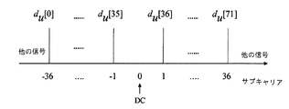
例えばOFDM伝送技術に基づくE−UTRAセルラーシステムにおけるダウンリンク信号は、伝送のために利用可能な帯域幅、いわゆるDCサブキャリア内の中心周波数を使用しないように指定される。この理由は、基地局の送信機または移動ユーザ装置(UE)の受信機のいずれかで起こり得る潜在的ローカル発信器漏洩がDCサブキャリアに重大な干渉を引き起こし、それによってこの装置を実際に使用できなくする可能性があるということである。 For example, the downlink signal in an E-UTRA cellular system based on OFDM transmission technology is specified not to use the bandwidth available for transmission, the center frequency in the so-called DC subcarrier. This is because potential local transmitter leakage that can occur at either the base station transmitter or the mobile user equipment (UE) receiver causes significant interference to the DC subcarrier, thereby actually using the device. There is a possibility of making it impossible.
E−UTRAセルラーシステムは、UEにおけるOFDM記号タイミング同期化をサポートするためにダウンリンク(DL)上で伝送される複数(3つ)の1次同期P−SCH信号を使用するように指定される。3つのP−SCH信号は、セル識別グループ内のセル識別情報に結合されており、この方法でタイミング同期目的と情報伝送との両方のために役立っている。 The E-UTRA cellular system is specified to use multiple (three) primary synchronized P-SCH signals transmitted on the downlink (DL) to support OFDM symbol timing synchronization at the UE. . The three P-SCH signals are combined with cell identification information in the cell identification group, which serves both for timing synchronization purposes and information transmission in this manner.
P−SCH信号は非反復性構造を有しており、Zadoff−Chu(ZC)系列に基づいている。P−SCH信号は、DCサブキャリアを中心とする最大72個のアクティブサブキャリアを有するOFDM信号である。アクティブサブキャリアは、ルートインデックスu=u1,u2,u3を有する3個の異なるZC系列の1セットから選択されたセル固有P−SCH数列du[n]のエレメントで変調される。利用可能なサブキャリアへの長さL=72の例示的P−SCH数列du[n],n=0,・・・,71の結果として得られたマッピングは、図3に略図的に示されている。同期信号のUEにおける受信は、好適には整合フィルタ受信機によって行われる。整合フィルタは、信号の完全な受信の瞬間においてフィルタの出力における信号対雑音比を最大にするように示され得る。相加性白色ガウス雑音(AWGN)チャネルを通過した信号に関する整合フィルタのインパルス応答は、伝送された信号の時間的逆バージョンに等しい。このような整合フィルタは、非AWGNチャネルに関する正確な整合フィルタの良好な近似がチャネル相関関数の知識を必要とするので、伝播チャネルがAWGNでない場合でも実際に使用される。 The P-SCH signal has a non-repetitive structure and is based on a Zadoff-Chu (ZC) sequence. A P-SCH signal is an OFDM signal having a maximum of 72 active subcarriers centered on a DC subcarrier. The active subcarrier is modulated with an element of a cell-specific P-SCH sequence d u [n] selected from a set of three different ZC sequences with root indices u = u 1 , u 2 , u 3 . The resulting mapping of an exemplary P-SCH sequence du [n], n = 0,..., 71 of length L = 72 to available subcarriers is shown schematically in FIG. Has been. The reception of the synchronization signal at the UE is preferably performed by a matched filter receiver. The matched filter may be shown to maximize the signal to noise ratio at the output of the filter at the moment of complete reception of the signal. The impulse response of the matched filter for a signal that has passed through an additive white Gaussian noise (AWGN) channel is equal to the temporal inverse version of the transmitted signal. Such a matched filter is actually used even when the propagation channel is not AWGN, because a good approximation of an exact matched filter for non-AWGN channels requires knowledge of the channel correlation function.
RAN WG1会議,48ビスからの2つの提案を比較すると、前者の提案で行われたトレードオフは1つの利用可能なサブキャリアが未使用のままに留まることである。これは、信号の周波数ダイバーシチを減らし、信号をフェージング伝播チャネルの効果により影響され易くする。信号帯域幅のより大きな削減は、信号の主要自己相関ローブの拡大に繋がり、これは信号タイミング推定の精度低下を意味する。前者の提案Package of PSC and SSC proposals for LTE cell search,R1−071497と比較して後者の提案Comparison of sequence and structure for P−SCH,R1−071531の欠点は、長さ72のZadoff−Chu系列の異なるルートインデックスから得られた多数の1次同期P−SCH信号の最大相互相関が、Zadoff−Chu系列の長さが71である場合より高いことである。 Comparing the two proposals from the RAN WG1 conference, 48 bis, the trade-off made in the former proposal is that one available subcarrier remains unused. This reduces the frequency diversity of the signal and makes the signal more susceptible to the effects of fading propagation channels. A greater reduction in signal bandwidth leads to an expansion of the main autocorrelation lobe of the signal, which means a decrease in the accuracy of signal timing estimation. Compared to the former proposal Package of PSC and SSC proposals for LTE cell search, R1-071497, the disadvantage of the latter proposal Comparison of sequence and structure for P-SCH, R1-071531 is that of length 72Ch The maximum cross-correlation of a large number of primary synchronization P-SCH signals obtained from different route indexes is higher than when the length of the Zadoff-Chu sequence is 71.
従来技術を改善するため、または従来技術の代替手段を提供するために本発明の例示的実施形態は、通信システムにおいて整合フィルタ受信機に特によく適した同期信号を確立するための方法、システムおよび装置提案し、本方法は、1セットの離散的フーリエ周波数係数Hu[l]を定義することと、前記1セットの離散的フーリエ周波数係数Hu[l]を離散的時間表現su[k]に変換することと、前記通信システムにおける前記同期信号としての前記離散的時間表現su[k]の使用のために前記通信システムを準備することと、を含む。 In order to improve the prior art or provide an alternative to the prior art, exemplary embodiments of the present invention provide a method, system, and method for establishing a synchronization signal that is particularly well suited for a matched filter receiver in a communication system. and device proposed, the method, a set of discrete Fourier frequency coefficients H u and you to define a [l], the discrete Fourier frequency coefficients of the set of H u [l] a discrete time representation s u [ including a Rukoto be converted into k], and the method comprising preparing the communication system for use of said discrete time representation s u [k] as the synchronization signal in said communication system.
「・・・の使用のために通信システムを準備すること」とは例えば、送信または受信時に同期信号を利用するためにシステム内のどこかに在るメモリに信号を記憶させることによって、あるいは通信システムの一部分をプログラムすることによって、指定された同期信号を使用できるように通信システムを準備することを含む。 "Preparing the communication system for use of ..." means, for example, by storing a signal in a memory somewhere in the system to utilize a synchronization signal during transmission or reception, or communication Including preparing the communication system to use a specified synchronization signal by programming a portion of the system.
前記1セットの離散的フーリエ周波数係数Hu[l]は好適には、中心対称であるように定義される。周波数表現が中心対称の場合、これは離散的時間表現su[k]も中心対称であるための必要十分な条件であることが以下に示される。これは、整合フィルタ受信機がRAN WG1会議,48ビスの前述の提案の場合よりはるかに効率的であるように設計されることが可能であることを意味する。 The set of discrete Fourier frequency coefficients H u [l] is preferably defined to be centrally symmetric. If the frequency representation is centrosymmetric, it is shown below that this is a necessary and sufficient condition for the discrete time representation s u [k] to also be centrosymmetric. This means that the matched filter receiver can be designed to be much more efficient than in the case of the previous proposal of the RAN WG1 conference, 48 bis.
本発明の一実施形態における信号の中心対称性の1つの動機は、信号波形の正確な知識が必須条件である整合フィルタ受信機等の受信機が効率的に実現されることである。 One motivation for the central symmetry of the signal in one embodiment of the present invention is that a receiver, such as a matched filter receiver, where accurate knowledge of the signal waveform is a prerequisite is efficiently realized.
本発明による例示的方法において離散的フーリエ周波数係数の1セットを定義するための1つの方法は、離散的フーリエ周波数係数Hu[l]の前記1セットを定義するためにこの例示的方法に、数列du[n]を定義することと、好適には中心対称である離散的フーリエ周波数係数Hu[l]の前記1セットに到達するように数列du[n]のマッピングを行うことと、を含ませることである。 One method for defining a set of discrete Fourier frequency coefficients in the exemplary method according to the present invention is to this exemplary method for defining said one set of discrete Fourier frequency coefficients H u [l]: and you to define a sequence d u [n], intends row mapping sequence d u [n] as preferably reaches the set of centrally symmetric and is discrete Fourier frequency coefficients H u [l] To include.
これは、3GPP Technical Specification,3GPP TS 36.211v1.0.0における規格にも準拠する係数Hu[l]を定義する便利な方法を可能にし、更に中心対称の好適な性質を保持する。 This allows a convenient way of defining the 3GPP Technical Specification, coefficients conforming to standards in 3GPP TS 36.211v1.0.0 H u [l] , further retain properties suitable centrosymmetric.
更に、本発明による方法について、数列du[n]を定義することは好適にはまた、前記数列du[n]を中心対称であるように定義することを含む。 Furthermore, for the method according to the invention, defining the sequence d u [n] preferably also includes defining the sequence d u [n] to be centrally symmetric.
更に、本発明の好適な実施形態では前記マッピングは、ゼロであるDCサブキャリアを有する離散的フーリエ周波数係数Hu[l]の前記1セットを有するように行われる。これは、3GPP Technical Specification,3GPP TS 36.211v1.0.0に在るようなDCキャリアがゼロであるための要件を有するシステムにおいて有利である。 Furthermore, in a preferred embodiment of the present invention, the mapping is performed to have the one set of discrete Fourier frequency coefficients H u [l] with DC subcarriers being zero. This is advantageous in systems that have a requirement for zero DC carrier, such as in 3GPP Technical Specification, 3GPP TS 36.211v1.0.0.
一例として本発明の方法によるマッピングは、

前記数列を定義することは、例えば、長さがLであってdu[n]=du[L−1−n], n=0,1,・・・,L/2−1といった性質を有する中心対称数列du[n]として前記数列を定義することを含む。したがってこれは、du[n]の中心対称性を与える。前記中心対称数列du[n]は、長さL/2の数列とその反転レプリカ(reverted replica)とを連結することによって定義され得る。これの一例として、ある数列が挙げられ得るが、前記中心対称数列du[n]は、
中心対称数列を取得するためのもう1つの方法は、du[n]が
数列du[n]が
![]()
![]()
![]()
![]()
これはサンプルsu[0]だけがその対称の相手方を有さないことを意味する。式5の証明は次のとおりである。すなわち、su[k]の定義、
応用ケースでは、前記中心対称数列を長さL=72を有するように定義する場合、その性能をRAN WG1会議,48ビスの前述の従来技術提案の数列から達成可能な性能と比較できる。これらの引用された文献の第1のものと比較されると、これはP−SCH信号のために利用可能なすべてのアクティブサブキャリアの利用を与える。RAN WG1会議,48ビスの両引用提案と比較されると、これは以下に論じられるように極めて低いペアワイズ非周期性相互相関と同期信号の極めて低い自己相関サイドローブと低いピーク対平均電力比PAPRとを有する同期信号を与える。 In an application case, if the centrosymmetric sequence is defined to have a length L = 72, its performance can be compared to the performance achievable from the aforementioned prior art sequence of RAN WG1 Conference, 48 bis. Compared to the first of these cited documents, this gives the utilization of all active subcarriers available for P-SCH signals. Compared to the RAN WG1 conference, 48 bis quoted proposal, this is a very low pairwise aperiodic cross-correlation, a very low autocorrelation sidelobe of the synchronization signal and a low peak-to-average power ratio PAPR as discussed below. A synchronization signal having
du[n]の長さLの選択がこの例示的長さに限定されず、用途に依存することはいうまでもない。一例として前記中心対称数列が長さL=64を有することは完全に可能である。 It goes without saying that the selection of the length L of du [n] is not limited to this exemplary length and depends on the application. As an example, it is perfectly possible for the centrally symmetric sequence to have a length L = 64.
本発明による通信システムにおける同期信号を確立する前述の方法は、例えば無線通信システムである通信システムのためにこのような同期信号を確立するある種の同期化を必要とする異なる通信システムにおいて同期信号を確立するために使用され得る。このような無線通信システムの一例は、セルラー通信システムにおけるOFDMダウンリンクチャネルである。このようなシステムは、3GPP Technical Specification,3GPP TS36.211v1.0.0に記載されている。 The above-described method for establishing a synchronization signal in a communication system according to the invention is a synchronization signal in a different communication system that requires some kind of synchronization to establish such a synchronization signal, for example for a communication system that is a wireless communication system. Can be used to establish One example of such a wireless communication system is an OFDM downlink channel in a cellular communication system. Such a system is described in 3GPP Technical Specification, 3GPP TS 36.211v1.0.0.
前述の本発明による方法のすべての特徴とそれらすべての異なる代替手段とが、それらの組み合わせが自己矛盾を意味しない限り、任意に組み合わせ可能であることは明記されるべきである。 It should be specified that all the features of the method according to the invention described above and all the different alternatives can be combined arbitrarily, so long as their combination does not imply self-contradiction.
一例として、ここで、3GPP Technical Specification,3GPP TS36.211v1.0.0に指定された仕様に準拠するシステムの場合に適用される本発明の識見を使用し、この応用ケースの性能をRAN WG1会議,48ビスの前記従来技術提案の性能と比較する。3GPP Technical Specification,3GPP TS36.211v1.0.0に指定され、図3に示されたようにDCサブキャリアは数列du[n]のエレメントをマップするために使用されることはできないが、du[n]のエレメントはDCサブキャリアを中心として連続して等間隔に配置された他のすべてのサブキャリアにマップされる。図3からのベースバンドP−SCH信号su[k],k=0,1,・・・,N−1は、例えば、
一例として、RAN WG1会議,48ビス,R1−071497の提案は、
128サンプルロング相関器のためのRAN WG1会議,48ビス,R1−071497からのP−SCH信号の非周期性相互/自己相関関数は図1に示されている。これらの信号のPAPR値は3.14dB、3.14dBおよび4.66dBである。 The aperiodic cross / autocorrelation function of the P-SCH signal from the RAN WG1 conference, 48 bis, R1-0771497 for a 128 sample long correlator is shown in FIG. The PAPR values for these signals are 3.14 dB, 3.14 dB and 4.66 dB.
もう1つの例として提案RAN WG1会議,48ビス,R1−071531は、
128サンプルロング相関器のための、またu=1,71,5に関するRAN WG1会議,48ビスからの提案R1−071531におけるP−SCH信号の非周期性相互/自己相関関数は図2に示されている。これらの信号のPAPR値は2.61dB、2.57dBおよび6.78dBである。 The aperiodic cross / autocorrelation function of the P-SCH signal for the 128 sample long correlator and in the RAN WG1 conference for u = 1,71,5, proposal R1-071531 from 48 Bis is shown in FIG. ing. The PAPR values for these signals are 2.61 dB, 2.57 dB and 6.78 dB.
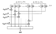
P−SCH信号のN−1個のサンプルの中心対称性は、P−SCH信号に対応する例示的整合フィルタにおける乗算の回数を減らすために使用され得る。例えばN=L+1=73の場合、P−SCH信号の72個の中心対称サンプルが存在するので、整合フィルタは、73回の乗算を必要とする直接実現と比較して約50%の削減になる1相関当たり1+72/2=37回の乗算によって実現され得る。これは図4に示されているが、この図で「*」は複素共役を意味する。 The central symmetry of the N-1 samples of the P-SCH signal can be used to reduce the number of multiplications in the exemplary matched filter corresponding to the P-SCH signal. For example, if N = L + 1 = 73, there are 72 centrally symmetric samples of the P-SCH signal, so the matched filter is reduced by about 50% compared to a direct implementation requiring 73 multiplications. It can be realized by 1 + 72/2 = 37 multiplications per correlation. This is illustrated in FIG. 4, where “*” means complex conjugate.
以下では、Zadoff−Chu系列(ZC)に基づく中心対称である例示的P−SCH数列du[n]を取得するための2つの手順または方法が論じられる。第1の方法は、長さL/2のZC系列とその反転レプリカとを連結することである。対応するP−SCH数列du[n]は式2、
第2の方法は、奇数長さL+1のZC系列の中心エレメントをパンクチャすることである。この場合、P−SCH数列du[n]は式3、
第2の代替手段は、より低い最大相互相関を有する例示的P−SCH信号を与える。 The second alternative provides an exemplary P-SCH signal with a lower maximum cross-correlation.
上記の論議から、長さ73の異なるZC系列の中心エレメントをパンクチャすることによって得られる、すなわち
128サンプルロング相関器を使用して式14から得られるP−SCH信号の非周期性相互/自己相関関数は図5に示されている。本発明にしたがって得られたPAPR値は2.98dB、2.98dBおよび4.43dBであって、すなわち従来技術のPAPR値より良好であるか、従来技術のPAPR値に相当している。 The aperiodic cross / autocorrelation function of the P-SCH signal obtained from Equation 14 using a 128 sample long correlator is shown in FIG. The PAPR values obtained according to the present invention are 2.98 dB, 2.98 dB and 4.43 dB, ie better than the prior art PAPR values or correspond to the prior art PAPR values.
ルートインデックスu3=L+1−u1を有する長さL+1のZadoff−Chu系列はルートインデックスu1を有する同じ長さのZC系列の複素共役バージョンであるから、これら2つの対応する整合フィルタは単に1つのフィルタの乗算の複雑さでもって実現され得る。 Since the length L + 1 Zadoff-Chu sequence with root index u 3 = L + 1−u 1 is a complex conjugate version of the same length ZC sequence with root index u 1 , these two corresponding matched filters are simply 1 It can be realized with the complexity of multiplying two filters.
中心対称であるフーリエ周波数係数に基づいて同期信号を指定することはRAN WG1会議,48ビスに関する前述の背景文献において明らかにされなかった識見から利益を得る、すなわちこのような同期信号の伝送は、例えばこのような信号を受信する受信機において相関器の対応するバンクの効率的実現を可能にするという利点を提供する。この利益は、従来技術文献の教示から達成され得るものを考慮すると驚くほどのものである。 Specifying a synchronization signal based on a Fourier frequency coefficient that is centrosymmetric benefits from the insights that were not revealed in the previous background document on the RAN WG1 Conference, 48 Bis, ie the transmission of such a synchronization signal is For example, it provides the advantage of allowing an efficient realization of a corresponding bank of correlators in a receiver receiving such signals. This benefit is surprising considering what can be achieved from the teachings of the prior art literature.
本発明の一実施形態のもう1つの実証された利点は、有利なピーク対平均電力比PAPRである。 Another demonstrated advantage of one embodiment of the present invention is an advantageous peak-to-average power ratio PAPR.
本発明の一実施形態によれば、本発明は同期信号を通信システムにおいて例えば整合フィルタ受信機に送信するように整えられる。同期信号は、1セットのフーリエ周波数係数Hu[l]を定義することと、前記1セットのフーリエ周波数係数Hu[l]を離散的時間表現su[k]に変換することと、から確立され、送信機が好適には前記離散的時間表現su[k]を前記通信システムにおける前記同期信号として使用するように整えられる。 According to an embodiment of the present invention, the present invention is Ru are arranged to transmit in a communication system a synchronization signal for example matched filter receiver. Synchronization signal, and Rukoto be converted to the you to define a set of Fourier frequency coefficients H u [l], wherein the set of discrete time representation s u [k] Fourier frequency coefficients H u [l] of , established from, trimmed et be so in preferred transmitter using said discrete time representation s u [k], as the synchronization signal in said communication system.
一例示的実施形態では送信機は前記離散的時間表現su[k]を前記通信システムにおける前記同期信号として使用するように整えられており、前記離散的時間表現su[k]は前記1セットの離散的フーリエ周波数係数Hu[l]が中心対称であるようなものである。 The one transmitter in the exemplary embodiment has been arranged to use said discrete time representation s u [k], as the synchronization signal in said communication system, said discrete time representation s u [k] is 1 It is such that the set of discrete Fourier frequency coefficients H u [l] is centrally symmetric.
図6は、本発明による例示的通信システムの送信機Tx(61)と受信機Rx(65)とを略図的に示している。 FIG. 6 schematically shows a transmitter Tx (61) and a receiver Rx (65) of an exemplary communication system according to the present invention.
基本的に送信機は、ある特定の用途のために所望されるように、上記の本発明の方法の、送信の観点からの如何なる特徴をも実行するように整えられ得る。送信機は、離散的時間表現su[k]を前記通信システムにおける前記同期信号として使用するように整えられる。これは、送信機が同期信号を使用するための構造を備えることを意味する。このような構造の非排他的な例は、電子メモリMT(64)とマイクロプロセッサμT(62)と電気信号を送信するための回路Tc(63)とを含む。 Basically, the transmitter can be arranged to carry out any features from the transmission point of view of the method of the invention described above, as desired for a particular application. The transmitter is arranged to use a discrete time representation s u [k] as the synchronization signal in the communication system. This means that the transmitter has a structure for using the synchronization signal. Non-exclusive examples of such structures include an electronic memory M T (64), a microprocessor μ T (62), and a circuit Tc (63) for transmitting electrical signals.
本発明の一実施形態において本発明は通信システムのための整合フィルタ型の受信機を包含しており、前記受信機は前記通信システムにおける同期信号を受信するように整えられており、前記同期信号は、1セットの離散的フーリエ周波数係数Hu[l]を定義することと、前記1セットの離散的フーリエ周波数係数Hu[l]を離散的時間表現su[k]に変換することと、から確立され、前記受信機は好適には前記離散的時間表現su[k]を前記通信システムにおける前記同期信号として受信するように整えられている。 In one embodiment of the present invention, the present invention includes a matched filter type receiver for a communication system, wherein the receiver is arranged to receive a synchronization signal in the communication system, and the synchronization signal is that converts into a you to define a set of discrete Fourier frequency coefficients H u [l], wherein the set of discrete Fourier frequency coefficients H u [l] a discrete time representation s u [k] The receiver is preferably arranged to receive the discrete time representation s u [k] as the synchronization signal in the communication system.
一例示的実施形態では、受信機は前記離散的時間表現su[k]を前記通信システムにおける前記同期信号として使用するように整えられており、前記離散的時間表現su[k]は前記1セットの離散的フーリエ周波数係数Hu[l]が中心対称であるようなものである。 In one exemplary embodiment, the receiver has been arranged to use said discrete time representation s u [k], as the synchronization signal in said communication system, said discrete time representation s u [k] is the It is such that a set of discrete Fourier frequency coefficients H u [l] is centrally symmetric.
基本的に受信機は、ある特定の用途のために所望されるように、上記の本発明の方法の、受信の観点からの如何なる特徴をも実行するように整えられ得る。受信機は好適には離散的時間表現su[k]を前記通信システムにおける前記同期信号として使用するように整えられる。これは、受信機が同期信号を使用するための構造を備えることを意味する。このような構造の非排他的な例は、電子メモリMR(68)とマイクロプロセッサμR(66)と電気信号を受信するための回路Rc(67)とを含む。 In essence, the receiver can be arranged to carry out any features from the reception point of view of the inventive method described above, as desired for a particular application. The receiver is preferably arranged to use a discrete time representation s u [k] as the synchronization signal in the communication system. This means that the receiver has a structure for using the synchronization signal. Non-exclusive examples of such structures include an electronic memory M R (68), a microprocessor μ R (66), and a circuit Rc (67) for receiving electrical signals.
本発明の一例示的実施形態において、本発明は、例示的整合フィルタ受信機に同期信号を送信するように整えられた送信機と、前記同期信号を受信するように整えられた、例示的整合フィルタ型の受信機と、を含む通信システムを包含しており、前記同期信号は、1セットの離散的フーリエ周波数係数Hu[l]を定義することと、前記1セットの離散的フーリエ周波数係数Hu[l]を離散的時間表現su[k]に変換することと、から確立され、前記送信機は好適には前記離散的時間表現su[k]を前記同期信号として送信するように整えられ、前記受信機は好適には前記離散的時間表現su[k]を前記同期信号として受信するように整えられる。本発明の好適なモードでは前記通信システムの送信機と受信機は前記離散的時間表現su[k]を前記同期信号として使用するように整えられる。前記離散的時間表現su[k]は前記1セットの離散的フーリエ周波数係数Hu[l]が中心対称であるようなものである。 In an exemplary embodiment of the present invention, the present invention provides an exemplary matched filter arranged to receive a synchronization signal and a transmitter arranged to transmit the synchronization signal to an exemplary matched filter receiver. and includes a communication system including a filter type receiver, wherein the synchronization signal includes a you to define a set of discrete Fourier frequency coefficients H u [l], wherein the set of discrete Fourier frequency and Rukoto to transform coefficients H u [l] in a discrete time representation s u [k], is established from the transmitter is preferably transmitting the discrete time representation s u [k] as the synchronization signal And the receiver is preferably arranged to receive the discrete time representation s u [k] as the synchronization signal. In a preferred mode of the invention, the transmitter and receiver of the communication system are arranged to use the discrete time representation s u [k] as the synchronization signal . The discrete time representation s u [k] is such that the set of discrete Fourier frequency coefficients H u [l] is centrally symmetric.
Claims (23)
1セットの離散的フーリエ周波数係数を定義し、
前記1セットの離散的フーリエ周波数係数を離散的時間表現に変換し、
前記離散的時間表現を通信システムにおける同期信号として使用する、
ことを含み、
前記1セットの離散的フーリエ周波数係数が中心対称数列の離散的フーリエ周波数係数へのマッピングを表し、
前記1セットの離散的フーリエ周波数係数は中心対称である1セットのフーリエ周波数係数であり、
前記中心対称数列は奇数長さL+1のZadoff−Chu系列の中心エレメントをパンクチャすることに対応する、
方法。 A method for establishing a synchronization signal for transmission in a communication system, comprising:
Define a set of discrete Fourier frequency coefficients,
Transforming the set of discrete Fourier frequency coefficients into a discrete time representation;
Using the discrete time representation as a synchronization signal in a communication system;
Look at including it,
Discrete Fourier frequency coefficients of the set is the table mapping to discrete Fourier frequency coefficients centrosymmetric sequence,
The set of discrete Fourier frequency coefficients is a set of Fourier frequency coefficients that are centrally symmetric;
The centrally symmetric sequence corresponds to puncturing the central element of an odd length L + 1 Zadoff-Chu sequence;
Method.
にしたがって実行され、ここで、du[n],n=0,1,・・・,L−1が数列を表し、Lが前記数列の長さであり、Hu[l],l=0,1,・・・,N−1が離散的フーリエ周波数係数を表し、Nが離散的フーリエ周波数係数の数である、請求項1又は2に記載の方法。 The mapping is
, Where d u [n], n = 0, 1,..., L−1 represents a sequence, L is the length of the sequence, and H u [l], l = 3. A method according to claim 1 or 2 , wherein 0, 1, ..., N-1 represent discrete Fourier frequency coefficients and N is the number of discrete Fourier frequency coefficients.
によって与えられ、ここで、正の整数NについてWN=exp(−j2π/N)である、請求項1〜4のいずれかに記載の方法。 Before SL centrosymmetric sequence d u [n] is obtained by puncturing the central elements of odd length L + 1 of the Zadoff-Chu sequence,
Given by, where, is a positive integer N for W N = exp (-j2π / N ), the method according to any one of claims 1 to 4.
に対応する離散的時間表現su[k]に変換され、ここで、Nが前記1セットの離散的フーリエ周波数係数の数であり、フーリエ周波数係数Hu[l],l=0,1,・・・,N−1である、請求項1〜8のいずれかに記載の方法。 The set of discrete Fourier frequency coefficients is:
To a discrete time representation s u [k], where N is the number of the set of discrete Fourier frequency coefficients, and Fourier frequency coefficients H u [l], l = 0,1, ..., the method according to any one of claims 1 to 8 , wherein N-1.
離散的フーリエ周波数係数の1セットを定義されることと、前記1セットの離散的フーリエ周波数係数が離散的時間表現に変換されることと、及び前記1セットの離散的フーリエ周波数係数が中心対称数列の離散的フーリエ周波数係数へのマッピングを表すように定義され、前記1セットの離散的フーリエ周波数係数は中心対称である1セットのフーリエ周波数係数であり、前記中心対称数列は奇数長さL+1のZadoff−Chu系列の中心エレメントをパンクチャすることに対応することと、を表す伝送のための前記同期信号を確立することに適応したマイクロプロセッサを有し、
前記送信するための回路が前記通信システムにおいて前記離散的時間表現に対応する同期信号を送信するために整えられる、
送信機。 A transmitter for the communication system, comprising a circuit for transmitting a synchronization signal established in the communication system,
Defining a set of discrete Fourier frequency coefficients; converting the set of discrete Fourier frequency coefficients into a discrete time representation; and the set of discrete Fourier frequency coefficients being a centrally symmetric sequence. Wherein the set of discrete Fourier frequency coefficients is a set of Fourier frequency coefficients that are centrosymmetric and the centrosymmetric sequence is an odd length L + 1 Zadoff -Corresponding to puncturing the central element of the Chu sequence; and having a microprocessor adapted to establish said synchronization signal for transmission representing
The circuitry for transmitting is arranged to transmit a synchronization signal corresponding to the discrete time representation in the communication system;
Transmitter.
離散的フーリエ周波数係数の1セットを定義されることと、前記1セットの離散的フーリエ周波数係数が離散的時間表現に変換されることと、及び前記1セットの離散的フーリエ周波数係数が中心対称数列の離散的フーリエ周波数係数へのマッピングを表すように定義され、前記1セットの離散的フーリエ周波数係数は中心対称である1セットのフーリエ周波数係数であり、前記中心対称数列は奇数長さL+1のZadoff−Chu系列の中心エレメントをパンクチャすることに対応することと、表す前記同期信号に前記受信機を同期させることに適応したマイクロプロセッサを有し、
前記受信するための回路が前記通信システムにおいて前記離散的時間表現に対応する同期信号を受信するために整えられる、
受信機。 A receiver for the communication system, comprising a circuit for receiving a synchronization signal established in the communication system,
Defining a set of discrete Fourier frequency coefficients; converting the set of discrete Fourier frequency coefficients into a discrete time representation; and the set of discrete Fourier frequency coefficients being a centrally symmetric sequence. Wherein the set of discrete Fourier frequency coefficients is a set of Fourier frequency coefficients that are centrosymmetric and the centrosymmetric sequence is an odd length L + 1 Zadoff Having a microprocessor adapted to puncture the central element of the Chu sequence and to synchronize the receiver to the synchronizing signal representing;
The circuitry for receiving is arranged to receive a synchronization signal corresponding to the discrete time representation in the communication system;
Receiving machine.
前記送信機は請求項15または16に記載の送信機であり、
前記受信機は請求項17〜22のいずれかに記載の受信機であり、
前記受信機は、信号波形の知識から前記送信機に同期するように適応している、
通信システム。 A communication system comprising a transmitter comprising a circuit for transmitting an established synchronization signal to a receiver and a receiver comprising a circuit for receiving the synchronization signal from the transmitter,
The transmitter is the transmitter according to claim 15 or 16 ,
The receiver is a receiver according to one of claims 17 to 2 2,
The receiver is adapted to synchronize with the transmitter from knowledge of the signal waveform;
Communications system.
Applications Claiming Priority (3)
| Application Number | Priority Date | Filing Date | Title |
|---|---|---|---|
| SE0701056-4 | 2007-05-02 | ||
| SE0701056 | 2007-05-02 | ||
| PCT/CN2008/070844 WO2008134976A1 (en) | 2007-05-02 | 2008-04-29 | Method and apparatus of establishing a synchronisation signal in a communication system |
Related Child Applications (1)
| Application Number | Title | Priority Date | Filing Date |
|---|---|---|---|
| JP2013107649A Division JP5642838B2 (en) | 2007-05-02 | 2013-05-22 | Method, apparatus, system and program for establishing synchronization signal in communication system |
Publications (2)
| Publication Number | Publication Date |
|---|---|
| JP2010517452A JP2010517452A (en) | 2010-05-20 |
| JP5280376B2 true JP5280376B2 (en) | 2013-09-04 |
Family
ID=39943135
Family Applications (3)
| Application Number | Title | Priority Date | Filing Date |
|---|---|---|---|
| JP2009547518A Active JP5280376B2 (en) | 2007-05-02 | 2008-04-29 | Method and apparatus for establishing a synchronization signal in a communication system |
| JP2013107649A Active JP5642838B2 (en) | 2007-05-02 | 2013-05-22 | Method, apparatus, system and program for establishing synchronization signal in communication system |
| JP2014219994A Active JP6080050B2 (en) | 2007-05-02 | 2014-10-29 | Program for establishing a synchronization signal in a communication system |
Family Applications After (2)
| Application Number | Title | Priority Date | Filing Date |
|---|---|---|---|
| JP2013107649A Active JP5642838B2 (en) | 2007-05-02 | 2013-05-22 | Method, apparatus, system and program for establishing synchronization signal in communication system |
| JP2014219994A Active JP6080050B2 (en) | 2007-05-02 | 2014-10-29 | Program for establishing a synchronization signal in a communication system |
Country Status (13)
| Country | Link |
|---|---|
| US (1) | US7751490B2 (en) |
| EP (1) | EP2090050B2 (en) |
| JP (3) | JP5280376B2 (en) |
| CN (1) | CN101299742B (en) |
| AT (1) | ATE495616T2 (en) |
| BR (1) | BRPI0807071B1 (en) |
| DE (2) | DE602008004427D1 (en) |
| DK (1) | DK2090050T4 (en) |
| ES (1) | ES2361108T5 (en) |
| PL (1) | PL2090050T5 (en) |
| PT (1) | PT2090050E (en) |
| SI (1) | SI2090050T2 (en) |
| WO (1) | WO2008134976A1 (en) |
Cited By (1)
| Publication number | Priority date | Publication date | Assignee | Title |
|---|---|---|---|---|
| JP2015053717A (en) * | 2007-05-02 | 2015-03-19 | ファーウェイ テクノロジーズ カンパニー リミテッド | Program for establishing synchronization signal in communication system |
Families Citing this family (29)
| Publication number | Priority date | Publication date | Assignee | Title |
|---|---|---|---|---|
| DE602006016492D1 (en) | 2006-01-18 | 2010-10-07 | Huawei Tech Co Ltd | ORMATION TRANSMISSION IN A COMMUNICATION SYSTEM |
| GB2458418B (en) | 2006-12-19 | 2011-08-03 | Lg Electronics Inc | Sequence generating method for efficient detection and method for transmitting and receiving signals using the same |
| US8223908B2 (en) * | 2007-05-02 | 2012-07-17 | Qualcomm Incorporated | Selection of acquisition sequences for optimal frequency offset estimation |
| DK2145420T3 (en) * | 2007-05-17 | 2013-01-07 | Lg Electronics Inc | Method of sending synchronization signal in wireless communication system |
| KR100938756B1 (en) | 2007-07-06 | 2010-01-26 | 엘지전자 주식회사 | Method for performing cell search procedure in wireless communication system |
| KR101231512B1 (en) * | 2008-05-09 | 2013-02-07 | 한국전자통신연구원 | Symbol timing synchronization method and apparatus robust to frequency offset in wireless communication systems |
| JP4652443B2 (en) * | 2008-12-26 | 2011-03-16 | 富士通株式会社 | Discrete Fourier transform arithmetic processing apparatus and wireless communication apparatus |
| WO2011022885A1 (en) * | 2009-08-26 | 2011-03-03 | Huawei Technologies Co., Ltd. | Method for generating dft coefficients |
| CN103262447A (en) * | 2011-03-14 | 2013-08-21 | 日电(中国)有限公司 | Method and apparatus for primary synchronization signal detection |
| US20120269142A1 (en) * | 2011-04-24 | 2012-10-25 | Broadcom Corporation | Doppler adaptation using pilot patterns within single user, multiple user, multiple access, and/or MIMO wireless communications |
| CN102761355A (en) * | 2011-04-29 | 2012-10-31 | 华为技术有限公司 | Method and device for communication of control channel |
| CN102143103A (en) * | 2011-05-19 | 2011-08-03 | 新邮通信设备有限公司 | Method for generating pilot frequency sequence |
| WO2013044473A1 (en) * | 2011-09-29 | 2013-04-04 | Huawei Technologies Co., Ltd. | Method for generating synchronization signals for wireless communication systems |
| JP5712953B2 (en) * | 2012-03-08 | 2015-05-07 | アイコム株式会社 | COMMUNICATION DEVICE AND COMMUNICATION METHOD |
| JP6020998B2 (en) * | 2012-09-18 | 2016-11-02 | 国立大学法人茨城大学 | Wireless communication system and wireless communication method |
| US9615341B2 (en) * | 2013-11-01 | 2017-04-04 | Futurewei Technologies, Inc. | System and method for transmitting a synchronization signal |
| RU2656609C2 (en) | 2013-11-01 | 2018-06-06 | Хуавэй Текнолоджиз Ко., Лтд. | Transmitter, receiver and method for generating synchronization signals |
| US9973362B2 (en) * | 2014-03-07 | 2018-05-15 | Huawei Technologies Co., Ltd. | Common broadcast channel low PAPR signaling in massive MIMO systems |
| WO2016041463A1 (en) * | 2014-09-18 | 2016-03-24 | Huawei Technologies Co., Ltd. | Common broadcast channel low papr signaling in massive mimo systems |
| WO2016049270A2 (en) * | 2014-09-25 | 2016-03-31 | Intel Corporation | User equipment and synchronization methods for device to device (d2d) communication |
| US10200872B2 (en) * | 2014-10-08 | 2019-02-05 | Qualcomm Incorporated | DC subcarrier handling in narrowband devices |
| CN104410597B (en) * | 2014-11-20 | 2017-09-01 | 武汉邮电科学研究院 | A kind of ofdm signal time-domain synchronizing method based on the synchronous header sequence of two-stage |
| WO2016141992A1 (en) * | 2015-03-12 | 2016-09-15 | Huawei Technologies Co., Ltd. | Transmitting device, receiving device and methods thereof |
| US10165536B2 (en) * | 2015-06-19 | 2018-12-25 | Qualcomm Incorporated | System scanning and acquisition |
| US10200874B2 (en) * | 2016-09-29 | 2019-02-05 | Qualcomm Incorporated | Signature sequence for system identification in a shared spectrum |
| WO2018058547A1 (en) * | 2016-09-30 | 2018-04-05 | Nec Corporation | Methods and apparatuses for synchronous signal transmission |
| CN109997382B (en) | 2017-10-31 | 2022-07-26 | 瑞典爱立信有限公司 | Indication of subcarrier spacing parameter set |
| CN110266429A (en) * | 2019-04-18 | 2019-09-20 | 四川大学 | A kind of signal frame structure detection method based on Higher Order Cumulants |
| CN111970063B (en) * | 2020-08-26 | 2022-04-29 | 北京字节跳动网络技术有限公司 | Communication method, device, equipment and storage medium |
Family Cites Families (15)
| Publication number | Priority date | Publication date | Assignee | Title |
|---|---|---|---|---|
| EP1018827B1 (en) * | 1999-01-08 | 2004-05-06 | Sony International (Europe) GmbH | Synchronisation structure for OFDM system |
| DE69932150T2 (en) | 1999-04-23 | 2006-11-09 | Sony Deutschland Gmbh | Synchronization preamble in an OFDM system |
| JP4288777B2 (en) * | 1999-08-11 | 2009-07-01 | ソニー株式会社 | Multi-carrier signal transmitter and multi-carrier signal receiver |
| KR100377356B1 (en) * | 2000-05-19 | 2003-03-26 | 삼성전자주식회사 | Symbol and/or frequency Synchronization of Orthogonal Frequency Division Multiplexed signals |
| CN1780276B (en) | 2004-11-25 | 2012-01-04 | 都科摩(北京)通信技术研究中心有限公司 | Combined time synchronizing and frequency bias evaluation and evaluating device for orthogonal frequency division duplex system |
| US7830998B2 (en) | 2006-01-17 | 2010-11-09 | Edgewater Computer Systems, Inc. | Approximate linear FM synchronization symbols for a bandwidth configurable OFDM modem |
| GB2450428B (en) | 2006-01-17 | 2011-02-09 | Edgewater Comp Systems Inc | Approximate linear FM synchronization symbols for a bandwidth configurable OFDM modem |
| DE602006016492D1 (en) * | 2006-01-18 | 2010-10-07 | Huawei Tech Co Ltd | ORMATION TRANSMISSION IN A COMMUNICATION SYSTEM |
| US7911935B2 (en) * | 2006-02-08 | 2011-03-22 | Motorola Mobility, Inc. | Method and apparatus for interleaving sequence elements of an OFDMA synchronization channel |
| US7706249B2 (en) | 2006-02-08 | 2010-04-27 | Motorola, Inc. | Method and apparatus for a synchronization channel in an OFDMA system |
| EP1994703A1 (en) | 2006-03-07 | 2008-11-26 | Koninklijke Philips Electronics N.V. | Synchronization sequence with tone notching in ofdm systems |
| US20080002566A1 (en) | 2006-06-29 | 2008-01-03 | Zhongshan Zhang | Training sequence generating method, a communication system and communication method |
| WO2008018145A1 (en) * | 2006-08-10 | 2008-02-14 | Panasonic Corporation | Ofdm transmitter apparatus and ofdm receiver apparatus |
| ATE495616T2 (en) * | 2007-05-02 | 2011-01-15 | Huawei Tech Co Ltd | METHOD AND DEVICE FOR SETTING UP A SYNCHRONIZING SIGNAL IN A SWITCHING SYSTEM |
| US8223908B2 (en) * | 2007-05-02 | 2012-07-17 | Qualcomm Incorporated | Selection of acquisition sequences for optimal frequency offset estimation |
-
2008
- 2008-04-29 AT AT08734202T patent/ATE495616T2/en active
- 2008-04-29 BR BRPI0807071A patent/BRPI0807071B1/en active IP Right Grant
- 2008-04-29 PT PT08734202T patent/PT2090050E/en unknown
- 2008-04-29 PL PL08734202T patent/PL2090050T5/en unknown
- 2008-04-29 DE DE602008004427T patent/DE602008004427D1/en active Active
- 2008-04-29 WO PCT/CN2008/070844 patent/WO2008134976A1/en active Application Filing
- 2008-04-29 ES ES08734202.8T patent/ES2361108T5/en active Active
- 2008-04-29 DE DE202008018579.3U patent/DE202008018579U1/en not_active Expired - Lifetime
- 2008-04-29 EP EP08734202.8A patent/EP2090050B2/en active Active
- 2008-04-29 JP JP2009547518A patent/JP5280376B2/en active Active
- 2008-04-29 DK DK08734202.8T patent/DK2090050T4/en active
- 2008-04-29 SI SI200830205T patent/SI2090050T2/en unknown
- 2008-04-30 CN CN2008100944968A patent/CN101299742B/en active Active
-
2009
- 2009-10-28 US US12/607,790 patent/US7751490B2/en active Active
-
2013
- 2013-05-22 JP JP2013107649A patent/JP5642838B2/en active Active
-
2014
- 2014-10-29 JP JP2014219994A patent/JP6080050B2/en active Active
Cited By (1)
| Publication number | Priority date | Publication date | Assignee | Title |
|---|---|---|---|---|
| JP2015053717A (en) * | 2007-05-02 | 2015-03-19 | ファーウェイ テクノロジーズ カンパニー リミテッド | Program for establishing synchronization signal in communication system |
Also Published As
| Publication number | Publication date |
|---|---|
| EP2090050B2 (en) | 2017-06-07 |
| JP2010517452A (en) | 2010-05-20 |
| JP6080050B2 (en) | 2017-02-15 |
| ATE495616T2 (en) | 2011-01-15 |
| EP2090050B1 (en) | 2011-01-12 |
| EP2090050A4 (en) | 2010-02-17 |
| CN101299742A (en) | 2008-11-05 |
| JP2015053717A (en) | 2015-03-19 |
| BRPI0807071B1 (en) | 2017-01-17 |
| US7751490B2 (en) | 2010-07-06 |
| ES2361108T3 (en) | 2011-06-14 |
| US20100034305A1 (en) | 2010-02-11 |
| WO2008134976A1 (en) | 2008-11-13 |
| DK2090050T3 (en) | 2011-05-02 |
| PT2090050E (en) | 2011-04-14 |
| JP2013179684A (en) | 2013-09-09 |
| CN101299742B (en) | 2010-12-01 |
| PL2090050T3 (en) | 2011-10-31 |
| ES2361108T5 (en) | 2017-10-31 |
| DK2090050T4 (en) | 2017-09-25 |
| EP2090050A1 (en) | 2009-08-19 |
| PL2090050T5 (en) | 2018-02-28 |
| JP5642838B2 (en) | 2014-12-17 |
| BRPI0807071A2 (en) | 2014-04-08 |
| SI2090050T2 (en) | 2017-10-30 |
| SI2090050T1 (en) | 2011-05-31 |
| DE602008004427D1 (en) | 2011-02-24 |
| DE202008018579U1 (en) | 2016-01-14 |
Similar Documents
| Publication | Publication Date | Title |
|---|---|---|
| JP5280376B2 (en) | Method and apparatus for establishing a synchronization signal in a communication system | |
| US10779330B2 (en) | Method, apparatus and system for random access | |
| CN101183895B (en) | Mobile communication system, transmitting apparatus and transmission signal generation method | |
| KR101080906B1 (en) | Apparatus for acquired preamble sequence | |
| KR20090075609A (en) | Method for obtaining synchronization signal in wireless communication system | |
| US10135654B2 (en) | Method and apparatus for generating code sequence in a communication system | |
| KR101181976B1 (en) | Apparatus for acquired preamble sequence | |
| KR101479776B1 (en) | Method for performing cell search procedure in wireless communication system | |
| KR100567313B1 (en) | Method for searching cell in orthogonal frequency division multiple access system | |
| Silva et al. | Cell search in long term evolution systems: primary and secondary synchronization | |
| CN102316067B (en) | Synchronization method in communication system and system | |
| Lin et al. | Improved joint correlated detection in cell search and synchronization procedure in 3GPP LTE downlink system | |
| WO2007126280A2 (en) | Method and apparatus for generating code sequence in a communication system | |
| CN102325116B (en) | Synchronization method and system in communication system | |
| JP5875561B2 (en) | Method for improving synchronization and information transmission in a communication system | |
| JP5988622B2 (en) | Method for improving synchronization and information transmission in a communication system | |
| CN102316575A (en) | Synchronized method and system thereof in communication system | |
| BR122015026521B1 (en) | METHOD, TRANSMITTER, RECEIVER AND SYSTEM FOR ESTABLISHING A SYNCHRONIZATION SIGNAL FOR TRANSMISSION IN A COMMUNICATION SYSTEM |
Legal Events
| Date | Code | Title | Description |
|---|---|---|---|
| A977 | Report on retrieval |
Free format text: JAPANESE INTERMEDIATE CODE: A971007 Effective date: 20111227 |
|
| A131 | Notification of reasons for refusal |
Free format text: JAPANESE INTERMEDIATE CODE: A131 Effective date: 20120207 |
|
| A601 | Written request for extension of time |
Free format text: JAPANESE INTERMEDIATE CODE: A601 Effective date: 20120501 |
|
| A602 | Written permission of extension of time |
Free format text: JAPANESE INTERMEDIATE CODE: A602 Effective date: 20120510 |
|
| A521 | Request for written amendment filed |
Free format text: JAPANESE INTERMEDIATE CODE: A523 Effective date: 20120807 |
|
| A131 | Notification of reasons for refusal |
Free format text: JAPANESE INTERMEDIATE CODE: A131 Effective date: 20120911 |
|
| A601 | Written request for extension of time |
Free format text: JAPANESE INTERMEDIATE CODE: A601 Effective date: 20121207 |
|
| A602 | Written permission of extension of time |
Free format text: JAPANESE INTERMEDIATE CODE: A602 Effective date: 20121214 |
|
| TRDD | Decision of grant or rejection written | ||
| A01 | Written decision to grant a patent or to grant a registration (utility model) |
Free format text: JAPANESE INTERMEDIATE CODE: A01 Effective date: 20130423 |
|
| A61 | First payment of annual fees (during grant procedure) |
Free format text: JAPANESE INTERMEDIATE CODE: A61 Effective date: 20130522 |
|
| R150 | Certificate of patent or registration of utility model |
Free format text: JAPANESE INTERMEDIATE CODE: R150 Ref document number: 5280376 Country of ref document: JP Free format text: JAPANESE INTERMEDIATE CODE: R150 |
|
| R250 | Receipt of annual fees |
Free format text: JAPANESE INTERMEDIATE CODE: R250 |
|
| R250 | Receipt of annual fees |
Free format text: JAPANESE INTERMEDIATE CODE: R250 |
|
| R250 | Receipt of annual fees |
Free format text: JAPANESE INTERMEDIATE CODE: R250 |
|
| R250 | Receipt of annual fees |
Free format text: JAPANESE INTERMEDIATE CODE: R250 |
|
| R250 | Receipt of annual fees |
Free format text: JAPANESE INTERMEDIATE CODE: R250 |
|
| R250 | Receipt of annual fees |
Free format text: JAPANESE INTERMEDIATE CODE: R250 |
|
| R250 | Receipt of annual fees |
Free format text: JAPANESE INTERMEDIATE CODE: R250 |
|
| R250 | Receipt of annual fees |
Free format text: JAPANESE INTERMEDIATE CODE: R250 |
|
| R250 | Receipt of annual fees |
Free format text: JAPANESE INTERMEDIATE CODE: R250 |