JP5279709B2 - Electric machine with slanting pole boundary - Google Patents
Electric machine with slanting pole boundary Download PDFInfo
- Publication number
- JP5279709B2 JP5279709B2 JP2009519980A JP2009519980A JP5279709B2 JP 5279709 B2 JP5279709 B2 JP 5279709B2 JP 2009519980 A JP2009519980 A JP 2009519980A JP 2009519980 A JP2009519980 A JP 2009519980A JP 5279709 B2 JP5279709 B2 JP 5279709B2
- Authority
- JP
- Japan
- Prior art keywords
- component
- skew angle
- region
- boundary
- electric machine
- Prior art date
- Legal status (The legal status is an assumption and is not a legal conclusion. Google has not performed a legal analysis and makes no representation as to the accuracy of the status listed.)
- Expired - Fee Related
Links
Images


Classifications
-
- H—ELECTRICITY
- H02—GENERATION; CONVERSION OR DISTRIBUTION OF ELECTRIC POWER
- H02K—DYNAMO-ELECTRIC MACHINES
- H02K1/00—Details of the magnetic circuit
- H02K1/06—Details of the magnetic circuit characterised by the shape, form or construction
- H02K1/22—Rotating parts of the magnetic circuit
- H02K1/27—Rotor cores with permanent magnets
- H02K1/2706—Inner rotors
- H02K1/272—Inner rotors the magnetisation axis of the magnets being perpendicular to the rotor axis
- H02K1/274—Inner rotors the magnetisation axis of the magnets being perpendicular to the rotor axis the rotor consisting of two or more circumferentially positioned magnets
- H02K1/2753—Inner rotors the magnetisation axis of the magnets being perpendicular to the rotor axis the rotor consisting of two or more circumferentially positioned magnets the rotor consisting of magnets or groups of magnets arranged with alternating polarity
- H02K1/278—Surface mounted magnets; Inset magnets
-
- H—ELECTRICITY
- H02—GENERATION; CONVERSION OR DISTRIBUTION OF ELECTRIC POWER
- H02K—DYNAMO-ELECTRIC MACHINES
- H02K2201/00—Specific aspects not provided for in the other groups of this subclass relating to the magnetic circuits
- H02K2201/06—Magnetic cores, or permanent magnets characterised by their skew
-
- H—ELECTRICITY
- H02—GENERATION; CONVERSION OR DISTRIBUTION OF ELECTRIC POWER
- H02K—DYNAMO-ELECTRIC MACHINES
- H02K29/00—Motors or generators having non-mechanical commutating devices, e.g. discharge tubes or semiconductor devices
- H02K29/03—Motors or generators having non-mechanical commutating devices, e.g. discharge tubes or semiconductor devices with a magnetic circuit specially adapted for avoiding torque ripples or self-starting problems
Landscapes
- Engineering & Computer Science (AREA)
- Power Engineering (AREA)
- Permanent Field Magnets Of Synchronous Machinery (AREA)
- Iron Core Of Rotating Electric Machines (AREA)
- Linear Motors (AREA)
- Permanent Magnet Type Synchronous Machine (AREA)
Description
本発明は、第1構成部品(例えばロータ)と、移動方向で第2構成部品に対し移動可能な第1構成部品に磁気的に連結された第2構成部品(例えばステータ)とを有する電気機械に関する。更にこの電気機械は第1構成部品に磁極配列を有し、該磁極配列の磁極は移動方向で一方で第1磁界方向、他方で第1磁界方向とは逆向きの第2磁界方向を交互に向いている。異なる磁界方向の磁極間の境界は、第1構成部品の第1領域では移動方向に対し相対的に第1スキュー角に相応して推移し、第1構成部品の第2領域では第2スキュー角に相応して推移する。本発明は、特に回転型モータ又はリニア型モータに関する。 The present invention includes an electrical machine having a first component (eg, a rotor) and a second component (eg, a stator) magnetically coupled to the first component that is movable relative to the second component in the direction of movement. About. Further, the electric machine has a magnetic pole array in the first component, and the magnetic poles of the magnetic pole array alternately move in the first magnetic field direction on the one hand and on the other side in the second magnetic field direction opposite to the first magnetic field direction. It is suitable. The boundary between the magnetic poles in different magnetic field directions changes in accordance with the first skew angle relative to the moving direction in the first region of the first component, and the second skew angle in the second region of the first component. It changes according to. The present invention particularly relates to a rotary motor or a linear motor.
永久磁石電気機械の動作挙動に本質的影響を持つのは励磁磁界の形状である。その際多かれ少なかれ力リプル又はトルクリプルが常に観察される。これは、トルクの最大化と並んで最小にされねばならない。 It is the shape of the exciting magnetic field that has an essential influence on the operating behavior of the permanent magnet electric machine. In this case, more or less force ripples or torque ripples are always observed. This must be minimized alongside the maximization of torque.
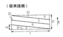
トルクリプルを改善するための有効な手段は、ステータおよび/又はロータを例えば1スロットピッチだけスキューさせることである。図1はロータを例にこのようなスキューを示し、このロータの周面を展開して図示している。こうして垂直方向で半周πrを示している。全体として、ロータは軸線方向で長さlを有する。異なる磁界方向又は磁化方向を有する永久磁石又は磁極がロータ表面に配置されている。これら磁化方向を図1にN、Sで表してある。異なる磁化方向の磁極の間を推移する境界G1は、例えばN極からS極へと、場合によっては連続的に、移行することを示している。 An effective means to improve torque ripple is to skew the stator and / or rotor by, for example, one slot pitch. FIG. 1 shows such a skew by taking a rotor as an example, and shows a developed peripheral surface of the rotor. Thus, the half circumference πr is shown in the vertical direction. Overall, the rotor has a length l in the axial direction. Permanent magnets or magnetic poles having different magnetic field directions or magnetization directions are arranged on the rotor surface. These magnetization directions are represented by N and S in FIG. The boundary G1 that transitions between the magnetic poles having different magnetization directions indicates that the transition occurs, for example, continuously from the north pole to the south pole.
ロータはステータに対し移動方向Bで移動する。境界G1は実質的に移動方向Bを横切って推移し、移動方向の垂線に対し軸線方向スキュー角βを成す。ロータの全長lを介して軸線方向スキュー角は弧度αrとなり、αはロータの中心角、rは半径である。 The rotor moves in the movement direction B with respect to the stator. The boundary G1 substantially moves across the movement direction B, and forms an axial skew angle β with respect to the perpendicular to the movement direction. Through the entire length l of the rotor, the axial skew angle becomes the arc degree αr, where α is the central angle of the rotor and r is the radius.
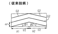
この軸線方向スキュー角βを特徴とする励磁磁界を有する電気機械は先行技術に数えられる。更に、図2に略示した如く、移動方向Bを横切って、即ち軸線方向で2つの領域A1、A2に区分されたロータを有する電気機械も公知である。更に、図3に示すように軸線方向で4つの区域A1、A2、A3、A4に区分されたロータも利用されている。各区域長はl/2又はl/4である。軸線方向スキュー又は境界G2、G3は、ここでは区域毎に直線的に推移する。図2の例によれば、区域A1では軸線方向スキュー角β1、区域A2では軸線方向スキュー角β2が生じる。β1=−β2、即ち|β1|=|β2|が成り立つ。図3の例における軸線方向スキュー角も、それらの値は相互に等しい。特許文献1により公知の磁石は図2又は図3と同様に複数の区域内で離散的磁化を可能とする。
特許文献2により、永久磁石ロータと対応した磁石型機械が公知である。ロータの磁石は互いに異なるスキュー角を持っている。
更に、特許文献3により、ブラシレスの永久磁石型電気機械が公知であり、そのロータは傾斜して磁化されている。異なる磁界方向における磁極間の境界は、ロータ上において異なる傾斜角を示す。更に、磁極間の境界は、中心対称に延びている。
特許文献4は、永久磁石のロータを備えたモータを開示している。永久磁石は周囲方向において交互に逆の極となるよう配置されている。隣接する2つの永久磁石間の境界は、正弦波状に又は3つの範囲において直線的に延びている。又、特許文献5により、磁石の境界が正弦波状に延びるモータが公知である。
特許文献6と7とにより、2つの磁化方向間の境界が、ロータ上を量子化されて延びるロータが公知である。
特許文献8は、力の変動を低減すべく、傾斜して延びる磁石を備えたリニアモータを開示している。
Electric machines having an exciting magnetic field characterized by this axial skew angle β are counted in the prior art. Further, as schematically shown in FIG. 2, an electric machine having a rotor that is divided into two regions A1 and A2 across the moving direction B, that is, in the axial direction, is also known. Further, as shown in FIG. 3, a rotor divided into four sections A1, A2, A3, and A4 in the axial direction is also used. Each zone length is l / 2 or l / 4. The axial skews or boundaries G2, G3 here vary linearly for each zone. According to the example of FIG. 2, an axial skew angle β1 occurs in the section A1, and an axial skew angle β2 occurs in the section A2. β1 = −β2, that is, | β1 | = | β2 | holds. The axial skew angles in the example of FIG. 3 are also equal to each other. The magnet known from Patent Document 1 enables discrete magnetization in a plurality of areas as in FIG. 2 or FIG.
According to
Furthermore, from Patent Document 3, a brushless permanent magnet type electric machine is known, and its rotor is tilted and magnetized. The boundaries between the magnetic poles in different magnetic field directions exhibit different tilt angles on the rotor. Further, the boundary between the magnetic poles extends in a central symmetry.
Patent Document 4 discloses a motor including a permanent magnet rotor. The permanent magnets are arranged so as to have opposite poles alternately in the circumferential direction. The boundary between two adjacent permanent magnets extends sinusoidally or linearly in three areas. Patent Document 5 discloses a motor in which the boundary between magnets extends in a sine wave shape.
Patent Documents 6 and 7 disclose a rotor in which a boundary between two magnetization directions is quantized and extends on the rotor.
Patent Document 8 discloses a linear motor including a magnet extending in an inclined manner in order to reduce force fluctuations.
本発明の課題は、電気機械の力リプル又はトルクリプルを更に減らすことである。 An object of the present invention is to further reduce the force ripple or torque ripple of an electric machine.
本発明によればこの課題は、電気機械であって、第1構成部品と、移動方向で第2構成部品に対し移動可能な第1構成部品に磁気的に連結された第2構成部品と、第1構成部品に形成され、その磁極が移動方向で一方で第1磁界方向、他方で第1磁界方向とは逆向きの第2磁界方向を交互に向く磁極配列とを有し、異なる磁界方向の磁極の間の境界が第1構成部品の第1領域では移動方向に対し相対的に第1スキュー角に相応して推移し、第1構成部品の第2領域では第2スキュー角に相応して推移するものにおいて、第1スキュー角が第2スキュー角とが別の値を有する電気機械によって解決される。 According to the invention, the object is an electrical machine, the first component and a second component magnetically coupled to the first component that is movable relative to the second component in the direction of movement, Different magnetic field directions, wherein the magnetic poles are formed on the first component and have a magnetic pole array alternately facing a first magnetic field direction on the one hand in the moving direction and a second magnetic field direction opposite to the first magnetic field direction on the other hand. The boundary between the magnetic poles of the first component in the first region of the first component changes relative to the direction of movement relative to the first skew angle, and the second region of the first component corresponds to the second skew angle. The first skew angle is solved by an electric machine having a different value from the second skew angle.
従って本発明によれば、トルクリプルはスキュー角の任意の機能によって様々に影響を及ぼすことができる。特に、このように決定された励磁磁界の高調波は消去又は最小にできる。例えば、軸端領域における漏れの影響は、軸線方向スキュー角の幾何学形状によって減らし得る。 Therefore, according to the present invention, torque ripple can be influenced in various ways by an arbitrary function of the skew angle. In particular, the harmonics of the excitation field determined in this way can be eliminated or minimized. For example, the effect of leakage in the axial end region can be reduced by the axial skew angle geometry.
好ましくは、本発明に係る電気機械の第1構成部品はロータ、第2構成部品はステータである。この場合、モータ又は発電機のトルクリプルは本発明に係る構造によって減らすことができる。 Preferably, the first component of the electric machine according to the present invention is a rotor, and the second component is a stator. In this case, the torque ripple of the motor or generator can be reduced by the structure according to the present invention.
選択的に、電気機械はリニアモータとして形成され、第1構成部品は一次部品、第2構成部品は二次部品である。電気機械のこの構成では、走行方向でのリニアモータの力リプルを減らし得る。 Optionally, the electric machine is formed as a linear motor, the first component being a primary part and the second component being a secondary part. This configuration of the electric machine can reduce the force ripple of the linear motor in the direction of travel.
移動方向において上で規定した第1領域における境界の長さは、電気機械の特殊な構成に応じて、第2領域における境界の長さに等しい(例えば1スロットピッチ)。しかし、第1領域における境界の長さは第2領域におけるよりも長くてもよい。応用事例に応じ、一方又は他方の変更態様が有利となる。 The boundary length in the first region defined above in the direction of movement is equal to the boundary length in the second region (eg, 1 slot pitch), depending on the particular configuration of the electric machine. However, the length of the boundary in the first region may be longer than that in the second region. Depending on the application, one or the other modification is advantageous.
他の好ましい実施形態によれば、異なる向きの磁極の間の境界は3つの区域において3つの異なるスキュー角で推移する。こうしてトルクリプルに対する多様で非対称な影響を考慮できる。 According to another preferred embodiment, the boundaries between the differently oriented poles transition in three zones with three different skew angles. In this way, various asymmetric influences on the torque ripple can be taken into account.
更に、境界の推移が実質的に移動方向を横切って中心対称又は軸対称であるとよい。これにより、例えばロータの場合軸線方向力を低減又は防止できる。 Furthermore, the transition of the boundary may be centrosymmetric or axisymmetric substantially across the direction of movement. Thereby, for example, in the case of a rotor, the axial force can be reduced or prevented.
特殊な実施形態では、異なる向きの磁極間の境界は実質正弦波状に推移し得る。境界の連続的推移は、同様にトルクリプル又は力リプルに対して肯定的に作用する。 In a special embodiment, the boundary between the magnetic poles in different orientations may transition in a substantially sinusoidal shape. The continuous transition of the boundary also acts positively on torque ripple or force ripple.
しかし、境界の推移は量子化(quantisieren)しておいてもよい。これは、矩形磁石要素の相応する配置によってスキュー角が模擬されることを意味する。その場合、境界は段階的に移動方向に沿って又はそれを横切って推移する。 However, the transition of the boundary may be quantized. This means that the skew angle is simulated by a corresponding arrangement of rectangular magnet elements. In that case, the boundary transitions stepwise along or across the direction of movement.
本発明を、添付図面に基づいて詳しく説明する。 The present invention will be described in detail with reference to the accompanying drawings.
以下で詳しく述べる実施例は、本発明の好ましい実施形態である。 The examples detailed below are preferred embodiments of the present invention.
少なくとも2つの異なる軸線方向スキュー角を使用する、本発明に係る基本的考えに基づく第1実施例を図4に示す。先行する図1〜図3におけると同様に、図4でもロータ表面の半分を展開して示す。ロータの軸線は図中水平方向にあり、移動方向Bはやはり垂直方向に推移する。電気機械は当然に方向を反転して移動してもよい。移動方向Bは、ここでは使用される角度および量を定義し説明するのに役立つにすぎない。 A first embodiment based on the basic idea according to the invention using at least two different axial skew angles is shown in FIG. As in the preceding FIGS. 1 to 3, FIG. 4 shows a half of the rotor surface in an expanded manner. The axis of the rotor is in the horizontal direction in the figure, and the moving direction B also changes in the vertical direction. Of course, the electric machine may move in the opposite direction. The direction of movement B serves only to define and explain the angles and quantities used here.
ロータはここでは2つの区域A1、A2に分割されている。第1区域A1は長さが3/8l、第2区域は長さが5/8lである。つまり区域の幅又は長さはここでは3/5の比である。この比は任意に別の比にも選択できる。例えば2/l又は1/lの比が特別有利である。 The rotor is here divided into two zones A1, A2. The first zone A1 is 3/8 l in length and the second zone is 5/8 l in length. That is, the width or length of the zone is here a ratio of 3/5. This ratio can be arbitrarily selected as another ratio. For example, a ratio of 2 / l or 1 / l is particularly advantageous.
第1区域A1におけるスキュー角はβ1、第2区域A2におけるスキュー角はβ2である。角度は異なる値と異なる前置符号を有する。スキュー、即ち異なる磁極の間の境界G4は、段差なしにロータの縦軸線の方向で恒常的に推移し、α×rの距離にある。 The skew angle in the first area A1 is β1, and the skew angle in the second area A2 is β2. The angles have different values and different prefix codes. The skew, i.e. the boundary G4 between the different magnetic poles, constantly changes in the direction of the longitudinal axis of the rotor without a step and is at a distance of [alpha] * r.
図5の実施例では、永久磁石を小さな磁石要素として形成している。個別磁石をロータ表面に配置すると、図4の磁極配列に一致した磁極配列が生ずる。各磁石要素の1つの磁極はロータ表面で上向きである。異なるハッチングを持つ、異なる磁極を図5に示す。異なる向きの永久磁石又は磁極の間の境界G5は、ここでは階段状に推移する。境界G5が直線化されると、図4の境界G4の推移と厳密に同じ推移が得られる。境界G4の恒常的推移は、例えばプラスチック結合磁石材料をロータに吹付けて相応に磁化することで得られる。選択的に、斜めに作製され予め磁化された高価な永久磁石を境界G4の恒常的推移用に利用できる。 In the embodiment of FIG. 5, the permanent magnet is formed as a small magnet element. When the individual magnets are arranged on the rotor surface, a magnetic pole arrangement corresponding to the magnetic pole arrangement shown in FIG. 4 is generated. One magnetic pole of each magnet element is upward on the rotor surface. Different magnetic poles with different hatching are shown in FIG. The boundary G5 between the differently oriented permanent magnets or magnetic poles here transitions stepwise. When the boundary G5 is straightened, the same transition as the transition of the boundary G4 in FIG. 4 is obtained. The constant transition of the boundary G4 is obtained, for example, by spraying a plastic bonded magnet material onto the rotor and magnetizing it accordingly. Alternatively, an expensive permanent magnet that is obliquely fabricated and pre-magnetized can be used for permanent transition of the boundary G4.
本発明の第3実施例を図6に示す。ここではロータ表面が軸線方向で3つの区域A1、A2、A3に分割されている。両方の外側区域A1、A3は幅が2/8l、従って中央区域A2は幅が4/8lである。軸線方向スキュー角は両方の区域A1、A3ではβ1、中央区域A2ではβ2である。図6の例においてβ2=0である。2つの境界線G5の間の距離はここでもαrである。単一の境界線G5が周方向で通過する弧度は、選択された例においてやはりαrである。 A third embodiment of the present invention is shown in FIG. Here, the rotor surface is divided into three zones A1, A2, A3 in the axial direction. Both outer sections A1, A3 are 2/8 l wide, so the central area A2 is 4/8 l wide. The axial skew angle is β1 in both zones A1, A3 and β2 in the central zone A2. In the example of FIG. 6, β2 = 0. The distance between the two boundary lines G5 is again αr. The arc degree through which the single boundary line G5 passes in the circumferential direction is again αr in the selected example.
図7に略示した第4実施例も、図6の実施例の量子化した態様を示す。境界G7はここでは、それが直線化されているとき、図6の境界G6と厳密に同じ推移である。 The fourth embodiment shown schematically in FIG. 7 also shows the quantized aspect of the embodiment of FIG. The boundary G7 now has exactly the same transition as the boundary G6 in FIG. 6 when it is linearized.
3つの異なる軸線方向スキュー角β1、β2、β3の第5実施例を図8に示す。幅l/8の第1区域A1ではスキュー角β1、長さ5/8lの第2区域A2ではスキュー角β2、長さ2/8lの第3区域A3ではスキュー角β3が実現されている。3つのスキュー角β1、β2、β3は全て、境界G8が各区域内で弧度αrを通過するような大きさである。
FIG. 8 shows a fifth embodiment of three different axial skew angles β1, β2, and β3. The skew angle β1 is realized in the first area A1 having the width l / 8, the skew angle β2 is realized in the second area A2 having the length 5 / 8l, and the skew angle β3 is realized in the third area A3 having the
図9による第6実施例は、図8の第5実施例の量子化した態様である。境界G9は、直線化した場合、境界G8と同じ推移を有する。 The sixth embodiment shown in FIG. 9 is a quantized mode of the fifth embodiment shown in FIG. The boundary G9 has the same transition as the boundary G8 when linearized.
図10に示す第7実施例は正弦波状磁化に関する。ここでは事実上無限に多くの軸線方向スキュー角があり、このスキュー角は正弦波関数から得られる。異なる向きの磁極間の境界G10は、ここではロータの軸線方向で複数の周期を有する。しかしこの境界は、例えば単に1周期又は1周期の微小部分を含むこともできる。境界G10が正弦波状推移の他に有することもできる推移は、別の関数で描くことができ、連続的に変化し、絶えず区別することのできるものである。 The seventh embodiment shown in FIG. 10 relates to sinusoidal magnetization. There are virtually infinitely many axial skew angles here, which can be obtained from a sinusoidal function. The boundary G10 between the magnetic poles in different directions has a plurality of periods in the axial direction of the rotor here. However, this boundary can also include, for example, only one period or a minute portion of one period. The transition that the boundary G10 can have in addition to the sinusoidal transition can be drawn with another function, changes continuously, and can be distinguished constantly.
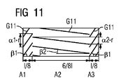
第8実施例を図11に略示する。ここでは2つの異なる軸線方向スキュー角β1、β2が区域A1、A2、A3内に設けられている。中央区域は、両方の区域A1、A3内の軸線方向スキュー角β1に比べて値の点で小さな勾配、即ち小さな軸線方向スキュー角β2を有する。これは、境界G11が両方の縁区域A1、A3内でここでは同じ勾配を有することを意味する。境界G11がここでは連続的に推移するのでなく、区域境界に段差を有する。区域A1、A3では境界G11の区域が弧度α1×rを通過する。それに対し、境界G11の部分は区域A2内で弧度α2×rを通過する。弧度α2×rは第1弧度α1×rよりも小さい。この変更態様は特にトルクリプルに対するコイル端漏れの影響の補償に役立つ。 An eighth embodiment is shown schematically in FIG. Here, two different axial skew angles β1, β2 are provided in the sections A1, A2, A3. The central zone has a small slope in value, ie a small axial skew angle β2, compared to the axial skew angle β1 in both zones A1, A3. This means that the boundary G11 now has the same slope in both edge areas A1, A3. The boundary G11 does not continuously change here, but has a step at the area boundary. In the sections A1 and A3, the section of the boundary G11 passes through the arc degree α1 × r. On the other hand, the part of the boundary G11 passes through the arc degree α2 × r in the area A2. The arc degree α2 × r is smaller than the first arc degree α1 × r. This modification is particularly useful for compensating for the effects of coil end leakage on torque ripple.
図12に示す第9実施形態は図11の磁石配列の量子化された実現態様に相当する。 The ninth embodiment shown in FIG. 12 corresponds to a quantized implementation of the magnet arrangement of FIG.
A1、A2 領域、B 移動方向、G1、G2 境界、N 第1磁界方向、S 第2磁界方向、β1、β2、β3 スキュー角 A1, A2 region, B movement direction, G1, G2 boundary, N first magnetic field direction, S second magnetic field direction, β1, β2, β3 Skew angle
Claims (5)
移動方向(B)で前記第1構成部品に対して移動可能な、前記第1構成部品に磁気的に連結された第2構成部品と、
前記第1構成部品に形成され、磁極が前記移動方向(B)において一方で第1磁界方向(N)、他方で前記第1磁界方向(N)とは逆向きの第2磁界方向(S)を交互に向く磁極配列とを有し、
異なった磁界方向の磁極間の境界(G1〜G11)が、前記第1構成部品の第1領域(A1)では、前記移動方向(B)に対し相対的に第1スキュー角(β1)に相応して推移し、前記第1構成部品の第2領域(A2)では、前記第2スキュー角(β2)に相応して推移する電気機械であって、
前記第1スキュー角(β1)が設定されている第1領域(A1)と前記第2スキュー角(β2)が設定されている第2領域(A2)とが、隣接して設けられていて、前記第1スキュー角(β1)が前記第2スキュー角(β2)とは別の値を有しており、さらに、
前記第2スキュー角(β2)が設定されている第2領域(A2)に隣接して、第3スキュー角(β3)が設定されている第3領域(A3)が設けられていて、前記第3スキュー角(β3)が、前記第1スキュー角(β1)とも前記第2スキュー角(β2)とも別の値を有している
ことを特徴とする電気機械。 A first component;
A second component magnetically coupled to the first component that is movable relative to the first component in a moving direction (B);
A second magnetic field direction (S) formed on the first component and having a magnetic pole opposite to the first magnetic field direction (N) on the one hand in the moving direction (B) and on the other hand. And a magnetic pole array facing alternately,
The boundaries (G1 to G11) between the magnetic poles in different magnetic field directions correspond to the first skew angle (β1) relative to the moving direction (B) in the first region (A1) of the first component. An electric machine that changes in accordance with the second skew angle (β2) in the second region (A2) of the first component,
The first region (A1) in which the first skew angle (β1) is set and the second region (A2) in which the second skew angle (β2) is set are provided adjacent to each other, The first skew angle (β1) has a value different from the second skew angle (β2), and
A third region (A3) in which a third skew angle (β3) is set is provided adjacent to the second region (A2) in which the second skew angle (β2) is set. An electrical machine characterized in that three skew angles (β3) have different values from both the first skew angle (β1) and the second skew angle (β2).
ことを特徴とする請求項1記載の電気機械。 2. The electric machine according to claim 1, wherein the first component is a rotor and the second component is a stator.
ことを特徴とする請求項1記載の電気機械。 2. The electric machine according to claim 1, wherein the electric machine is formed as a linear motor, wherein the first component is a primary component and the second component is a secondary component.
ことを特徴とする請求項1から3の1つに記載の電気機械。 The length along the direction orthogonal to the moving direction (B) of the boundaries (G1 to G11) between the magnetic poles in the different magnetic field directions adjacent in the moving direction (B) is the first region (A1). ), At least one of the length at the second region (A2) and the length at the third region (A3) is different from the others. The electrical machine described.
ことを特徴とする請求項1から4の1つに記載の電気機械。 Electrical machine according to one of claims 1 to 4, characterized in that transition of the boundary (G1~G11) is quantized.
Applications Claiming Priority (3)
| Application Number | Priority Date | Filing Date | Title |
|---|---|---|---|
| DE102006033718.2A DE102006033718B4 (en) | 2006-07-20 | 2006-07-20 | Electric machine with oblique magnetic pole boundaries |
| DE102006033718.2 | 2006-07-20 | ||
| PCT/EP2007/057433 WO2008009706A1 (en) | 2006-07-20 | 2007-07-18 | Electrical machine having diagonally extending magnetic pole boundaries |
Publications (3)
| Publication Number | Publication Date |
|---|---|
| JP2009544269A JP2009544269A (en) | 2009-12-10 |
| JP2009544269A5 JP2009544269A5 (en) | 2010-08-05 |
| JP5279709B2 true JP5279709B2 (en) | 2013-09-04 |
Family
ID=38596098
Family Applications (1)
| Application Number | Title | Priority Date | Filing Date |
|---|---|---|---|
| JP2009519980A Expired - Fee Related JP5279709B2 (en) | 2006-07-20 | 2007-07-18 | Electric machine with slanting pole boundary |
Country Status (4)
| Country | Link |
|---|---|
| US (1) | US8134273B2 (en) |
| JP (1) | JP5279709B2 (en) |
| DE (1) | DE102006033718B4 (en) |
| WO (1) | WO2008009706A1 (en) |
Families Citing this family (41)
| Publication number | Priority date | Publication date | Assignee | Title |
|---|---|---|---|---|
| JP4908178B2 (en) * | 2006-12-15 | 2012-04-04 | 東芝産業機器製造株式会社 | Rotating electric machine |
| EP2412077A4 (en) * | 2009-03-27 | 2017-04-26 | Otis Elevator Company | Electric machine having multidirectional skew |
| US20100277027A1 (en) * | 2009-04-30 | 2010-11-04 | Gm Global Technology Operations, Inc. | Skew pattern for a permanent magnet rotor |
| DE102010028872A1 (en) | 2010-05-11 | 2011-11-17 | Siemens Aktiengesellschaft | Drive device for rotary and linear movements with decoupled inertia |
| WO2012110532A2 (en) * | 2011-02-16 | 2012-08-23 | Max Bögl Bauunternehmung GmbH & Co. KG | Stator stack, supporting magnet and linear motor of a vehicle of a magnetic-levitation transport system |
| EP2508769B1 (en) | 2011-04-06 | 2013-06-19 | Siemens Aktiengesellschaft | Magnetic axial bearing device with increased iron filling |
| EP2604876B1 (en) | 2011-12-12 | 2019-09-25 | Siemens Aktiengesellschaft | Magnetic radial bearing with individual core plates in tangential direction |
| EP2639936B1 (en) | 2012-03-16 | 2015-04-29 | Siemens Aktiengesellschaft | Electrical machine with permanently excited rotor and permanently excited rotor |
| EP2639934B1 (en) | 2012-03-16 | 2015-04-29 | Siemens Aktiengesellschaft | Rotor with permanent excitation, electrical machine with such a rotor and method for producing the rotor |
| EP2639935B1 (en) | 2012-03-16 | 2014-11-26 | Siemens Aktiengesellschaft | Rotor with permanent excitation, electrical machine with such a rotor and method for producing the rotor |
| JP2013201810A (en) * | 2012-03-23 | 2013-10-03 | Hitachi Automotive Systems Ltd | Motor |
| DE102012205191A1 (en) | 2012-03-30 | 2013-10-02 | Bayerische Motoren Werke Aktiengesellschaft | Vibration prevention in synchronous machines |
| JP5929561B2 (en) * | 2012-06-29 | 2016-06-08 | 株式会社ジェイテクト | Electric rotating machine and manufacturing method thereof |
| EP2709238B1 (en) | 2012-09-13 | 2018-01-17 | Siemens Aktiengesellschaft | Permanently excited synchronous machine with ferrite magnets |
| DE102013009115A1 (en) * | 2012-09-14 | 2014-03-20 | Continental Automotive Gmbh | Rotor for a permanent-magnet electric machine and its use |
| DE102013206121A1 (en) * | 2013-04-08 | 2014-10-09 | Wobben Properties Gmbh | Synchronous generator Polpaket |
| EP2793363A1 (en) | 2013-04-16 | 2014-10-22 | Siemens Aktiengesellschaft | Single segment rotor with retaining rings |
| US10135309B2 (en) | 2013-04-17 | 2018-11-20 | Siemens Aktiengesellschaft | Electrical machine having a flux-concentrating permanent magnet rotor and reduction of the axial leakage flux |
| EP2838180B1 (en) | 2013-08-16 | 2020-01-15 | Siemens Aktiengesellschaft | Rotor of a dynamo-electric rotational machine |
| US10229777B2 (en) | 2013-10-31 | 2019-03-12 | General Electric Company | Graded magnetic component and method of forming |
| US10229776B2 (en) | 2013-10-31 | 2019-03-12 | General Electric Company | Multi-phase magnetic component and method of forming |
| EP2928052A1 (en) | 2014-04-01 | 2015-10-07 | Siemens Aktiengesellschaft | Electric machine with permanently excited internal stator and outer stator having windings |
| EP2999090B1 (en) | 2014-09-19 | 2017-08-30 | Siemens Aktiengesellschaft | Permanently excited rotor with a guided magnetic field |
| DE102014222044A1 (en) * | 2014-10-29 | 2016-05-19 | Volkswagen Aktiengesellschaft | Rotor of an electric machine, electric machine and method of manufacturing a rotor of an electric machine |
| EP3035496B1 (en) | 2014-12-16 | 2017-02-01 | Siemens Aktiengesellschaft | Rotor for a permanent magnet excited electric machine |
| MD3097102T2 (en) | 2015-03-04 | 2018-02-28 | Gilead Sciences Inc | Toll-like receptor modulating 4,6-diamino-pyrido[3,2-D]pyrimidine compounds |
| PT3507276T (en) | 2016-09-02 | 2022-01-11 | Gilead Sciences Inc | Toll like receptor modulator compounds |
| WO2018045150A1 (en) | 2016-09-02 | 2018-03-08 | Gilead Sciences, Inc. | 4,6-diamino-pyrido[3,2-d]pyrimidine derivaties as toll like receptor modulators |
| EP3373421B1 (en) | 2017-03-09 | 2019-11-20 | Siemens Aktiengesellschaft | Housing unit for an electric machine |
| CN108880030A (en) * | 2017-05-12 | 2018-11-23 | 蒂森克虏伯电梯(上海)有限公司 | Capstan rotor and traction machine with the rotor |
| CN107394922B (en) * | 2017-08-24 | 2023-11-14 | 智车优行科技(上海)有限公司 | Built-in permanent magnet motor rotor and permanent magnet motor |
| DE102018126570A1 (en) * | 2018-10-25 | 2020-04-30 | Bayerische Motoren Werke Aktiengesellschaft | rotor |
| TWI751517B (en) | 2019-04-17 | 2022-01-01 | 美商基利科學股份有限公司 | Solid forms of a toll-like receptor modulator |
| TW202210480A (en) | 2019-04-17 | 2022-03-16 | 美商基利科學股份有限公司 | Solid forms of a toll-like receptor modulator |
| TW202115056A (en) | 2019-06-28 | 2021-04-16 | 美商基利科學股份有限公司 | Processes for preparing toll-like receptor modulator compounds |
| DE102019123031A1 (en) * | 2019-08-28 | 2021-03-04 | Valeo Siemens Eautomotive Germany Gmbh | Electric machine rotor and electric machine |
| DE102019213891B4 (en) * | 2019-09-11 | 2021-07-08 | Vitesco Technologies Germany Gmbh | Rotor for an electric machine |
| KR20210068686A (en) * | 2019-12-02 | 2021-06-10 | 엘지전자 주식회사 | Vibration and noise reduction motor, rotor magnet structure of motor, and skew magnetizer yoke |
| FR3112906B1 (en) | 2020-07-23 | 2023-10-13 | Nidec Psa Emotors | rotating electric machine |
| US11661646B2 (en) | 2021-04-21 | 2023-05-30 | General Electric Comapny | Dual phase magnetic material component and method of its formation |
| US11926880B2 (en) | 2021-04-21 | 2024-03-12 | General Electric Company | Fabrication method for a component having magnetic and non-magnetic dual phases |
Family Cites Families (35)
| Publication number | Priority date | Publication date | Assignee | Title |
|---|---|---|---|---|
| BG39783A1 (en) * | 1984-05-08 | 1986-08-15 | Popov | Rotor with permanent magnets for electric machine |
| US4700096A (en) * | 1985-02-28 | 1987-10-13 | Auxilec | High speed synchronous machine having a rotor provided with magnets arranged for orthoradial magnetic induction |
| US4642502A (en) * | 1986-04-24 | 1987-02-10 | General Motors Corporation | Dynamoelectric machine with permanent magnet and magnet mounting surface arrangement |
| DE8803372U1 (en) * | 1988-03-12 | 1988-04-28 | Frankl & Kirchner Gmbh & Co Kg Fabrik Fuer Elektromotoren U. Elektrische Apparate, 6830 Schwetzingen, De | |
| US5034642A (en) * | 1990-08-30 | 1991-07-23 | Emerson Electric Co. | Permanent magnet rotor and motor |
| JPH05161287A (en) * | 1991-11-29 | 1993-06-25 | Fanuc Ltd | Rotor of synchronous apparatus |
| FR2685571A1 (en) * | 1991-12-20 | 1993-06-25 | Valeo Systemes Dessuyage | ROTOR WITH PERMANENT MAGNETS, AND MAGNETO-DYNAMIC MACHINE, LIKE AN ENGINE WITHOUT MANIFOLD, EQUIPPED WITH SUCH A ROTOR. |
| FR2685568B1 (en) * | 1991-12-20 | 1994-12-23 | Valeo Systemes Dessuyage | ROTOR WITH PERMANENT MAGNETS AND MAGNETO-DYNAMIC MACHINE, LIKE A MOTOR WITHOUT MANIFOLD, EQUIPPED WITH SUCH A ROTOR. |
| JPH08298735A (en) * | 1995-04-25 | 1996-11-12 | Fuji Electric Co Ltd | Cylindrical-permanent-magnet synchronous motor |
| JPH099602A (en) * | 1995-06-21 | 1997-01-10 | Toyoda Mach Works Ltd | Stepping motor |
| JPH11136893A (en) * | 1997-10-28 | 1999-05-21 | Toshiba Corp | Permanent magnet motor |
| HUP0102029A3 (en) * | 1998-06-26 | 2002-10-28 | Gen Electric | Rotor core, rotor and ac electric motor utilizing a stepped skew |
| JP3601757B2 (en) * | 1998-08-03 | 2004-12-15 | オークマ株式会社 | Permanent magnet motor |
| JP2000312448A (en) * | 1999-04-26 | 2000-11-07 | Seiko Instruments Inc | Electric motor |
| JP2001251838A (en) * | 2000-03-06 | 2001-09-14 | Genesis:Kk | Rotating machine with basic factor |
| JP4463947B2 (en) * | 2000-06-13 | 2010-05-19 | アイチエレック株式会社 | Structure of brushless DC motor |
| US6707209B2 (en) * | 2000-12-04 | 2004-03-16 | Emerson Electric Co. | Reduced cogging torque permanent magnet electric machine with rotor having offset sections |
| DE10147310B4 (en) * | 2001-09-26 | 2004-06-17 | Vacuumschmelze Gmbh & Co. Kg | Cup-shaped magnet |
| JP2003169452A (en) * | 2001-12-03 | 2003-06-13 | Daido Steel Co Ltd | Permanent magnet and permanent magnet motor using such |
| JP2003189589A (en) * | 2001-12-21 | 2003-07-04 | Canon Inc | Movable magnet type linear motor, exposure unit and method for manufacturing device |
| JP2003319582A (en) * | 2002-04-19 | 2003-11-07 | Yaskawa Electric Corp | Ac servo motor |
| DE10318278A1 (en) * | 2002-04-24 | 2003-11-06 | Papst Motoren Gmbh & Co Kg | Synchronous drive e.g. for fan, with electromagnetic stator and permanent magnet rotor provided by permanent magnet bands, rings, segments or discs attached to rotor |
| JP4101552B2 (en) * | 2002-04-30 | 2008-06-18 | 本田技研工業株式会社 | Electric power steering device |
| JP2003339129A (en) * | 2002-05-17 | 2003-11-28 | Mitsubishi Electric Corp | Permanent magnet dynamo-electric machine |
| DE10236609A1 (en) * | 2002-06-22 | 2004-01-08 | Zf Friedrichshafen Ag | Synchronous machine has magnets attached in shape-locking manner to periphery of rotor made of plates assembled with attachment arrangements into cylindrical plate packet |
| US7067948B2 (en) * | 2002-10-18 | 2006-06-27 | Mitsubishi Denki Kabushiki Kaisha | Permanent-magnet rotating machine |
| US6867524B2 (en) * | 2003-06-04 | 2005-03-15 | Ford Global Technologies, Llc | Rotor skew methods for permanent magnet motors |
| JP4089527B2 (en) * | 2003-06-27 | 2008-05-28 | 三菱電機株式会社 | Permanent magnet rotating electric machine |
| US6867525B2 (en) * | 2003-07-24 | 2005-03-15 | A.O. Smith Corporation | Brushless permanent magnet machine with axial modules of rotor magnetization skew and method of producing the same |
| DE102004045939B4 (en) * | 2004-09-22 | 2010-10-07 | Siemens Ag | Permanent magnet synchronous machine with suppressing means for improving torque ripple |
| EP1684400B1 (en) * | 2005-01-21 | 2008-05-14 | Hitachi, Ltd. | Rotating electric machine |
| US7348707B2 (en) * | 2005-11-30 | 2008-03-25 | General Electric Company | Electromechanical device having three-dimensional stator laminations |
| JP4376863B2 (en) * | 2005-12-22 | 2009-12-02 | シナノケンシ株式会社 | Permanent magnet type rotating machine |
| JP5123008B2 (en) * | 2008-03-05 | 2013-01-16 | 株式会社ミツバ | Brushless motor |
| JP5123009B2 (en) * | 2008-03-05 | 2013-01-16 | 株式会社ミツバ | Brushless motor |
-
2006
- 2006-07-20 DE DE102006033718.2A patent/DE102006033718B4/en not_active Expired - Fee Related
-
2007
- 2007-07-18 WO PCT/EP2007/057433 patent/WO2008009706A1/en active Application Filing
- 2007-07-18 JP JP2009519980A patent/JP5279709B2/en not_active Expired - Fee Related
- 2007-07-18 US US12/374,147 patent/US8134273B2/en not_active Expired - Fee Related
Also Published As
| Publication number | Publication date |
|---|---|
| DE102006033718A1 (en) | 2008-01-31 |
| DE102006033718B4 (en) | 2017-10-19 |
| WO2008009706A1 (en) | 2008-01-24 |
| JP2009544269A (en) | 2009-12-10 |
| US20100052466A1 (en) | 2010-03-04 |
| US8134273B2 (en) | 2012-03-13 |
Similar Documents
| Publication | Publication Date | Title |
|---|---|---|
| JP5279709B2 (en) | Electric machine with slanting pole boundary | |
| US9276443B2 (en) | Rotating element with embedded permanent magnet and rotating electrical machine | |
| KR101880377B1 (en) | Interior permanent magnet rotating electric machine | |
| US20060028082A1 (en) | Interior permanent magnet electric rotating machine | |
| US11456633B2 (en) | Permanent magnet rotating electric machine | |
| CN102223041B (en) | Motor | |
| EP2515417B1 (en) | A synchronous permanent magnet machine | |
| CN104937817A (en) | Rotor and rotating electrical machine equipped with rotor | |
| US6774521B2 (en) | Brushless DC motor | |
| CN111052546B (en) | Rotor of rotating electric machine | |
| JP5082241B2 (en) | Linear motor and method of manufacturing stator included therein | |
| JP2008148447A (en) | Motor for electric power steering device | |
| JP4855747B2 (en) | Permanent magnet type reluctance rotating electric machine | |
| CN111384799A (en) | Embedded permanent magnet motor and rotor comprising same | |
| US20080290754A1 (en) | AC Motor | |
| KR20110081189A (en) | Magnetic device for determining an angular position and generating a sinusoidal signal, and multiphase rotary electric machine including such a device | |
| JP2011193635A (en) | Brushless motor | |
| JP2005278268A (en) | Permanent magnet type motor | |
| JP2006025486A (en) | Electric electric machine | |
| JP2012023855A (en) | Permanent magnet embedded rotor and rotary electric machine | |
| JP2005328588A (en) | Permanent magnet motor | |
| JP6873335B1 (en) | Rotating machine | |
| JPH09163646A (en) | Electric motor | |
| JP2014087238A (en) | Rotary and linear synchronization motor | |
| JP2008253006A (en) | Permanent magnet arrangement structure of linear motion motor |
Legal Events
| Date | Code | Title | Description |
|---|---|---|---|
| A521 | Request for written amendment filed |
Free format text: JAPANESE INTERMEDIATE CODE: A523 Effective date: 20100616 |
|
| A621 | Written request for application examination |
Free format text: JAPANESE INTERMEDIATE CODE: A621 Effective date: 20100616 |
|
| A131 | Notification of reasons for refusal |
Free format text: JAPANESE INTERMEDIATE CODE: A131 Effective date: 20120605 |
|
| A521 | Request for written amendment filed |
Free format text: JAPANESE INTERMEDIATE CODE: A523 Effective date: 20120820 |
|
| RD03 | Notification of appointment of power of attorney |
Free format text: JAPANESE INTERMEDIATE CODE: A7423 Effective date: 20120820 |
|
| A131 | Notification of reasons for refusal |
Free format text: JAPANESE INTERMEDIATE CODE: A131 Effective date: 20121030 |
|
| A521 | Request for written amendment filed |
Free format text: JAPANESE INTERMEDIATE CODE: A523 Effective date: 20121128 |
|
| A131 | Notification of reasons for refusal |
Free format text: JAPANESE INTERMEDIATE CODE: A131 Effective date: 20130326 |
|
| A521 | Request for written amendment filed |
Free format text: JAPANESE INTERMEDIATE CODE: A523 Effective date: 20130326 |
|
| TRDD | Decision of grant or rejection written | ||
| A01 | Written decision to grant a patent or to grant a registration (utility model) |
Free format text: JAPANESE INTERMEDIATE CODE: A01 Effective date: 20130423 |
|
| A61 | First payment of annual fees (during grant procedure) |
Free format text: JAPANESE INTERMEDIATE CODE: A61 Effective date: 20130521 |
|
| R150 | Certificate of patent or registration of utility model |
Free format text: JAPANESE INTERMEDIATE CODE: R150 Ref document number: 5279709 Country of ref document: JP Free format text: JAPANESE INTERMEDIATE CODE: R150 |
|
| R250 | Receipt of annual fees |
Free format text: JAPANESE INTERMEDIATE CODE: R250 |
|
| R250 | Receipt of annual fees |
Free format text: JAPANESE INTERMEDIATE CODE: R250 |
|
| R250 | Receipt of annual fees |
Free format text: JAPANESE INTERMEDIATE CODE: R250 |
|
| R250 | Receipt of annual fees |
Free format text: JAPANESE INTERMEDIATE CODE: R250 |
|
| R250 | Receipt of annual fees |
Free format text: JAPANESE INTERMEDIATE CODE: R250 |
|
| R250 | Receipt of annual fees |
Free format text: JAPANESE INTERMEDIATE CODE: R250 |
|
| LAPS | Cancellation because of no payment of annual fees |