JP5278043B2 - Coin storage device - Google Patents

Coin storage device Download PDF

Info

Publication number
JP5278043B2
JP5278043B2 JP2009047191A JP2009047191A JP5278043B2 JP 5278043 B2 JP5278043 B2 JP 5278043B2 JP 2009047191 A JP2009047191 A JP 2009047191A JP 2009047191 A JP2009047191 A JP 2009047191A JP 5278043 B2 JP5278043 B2 JP 5278043B2
Authority
JP
Japan
Prior art keywords
storage
coin
storage box
coin storage
box
Prior art date
Legal status (The legal status is an assumption and is not a legal conclusion. Google has not performed a legal analysis and makes no representation as to the accuracy of the status listed.)
Active
Application number
JP2009047191A
Other languages
Japanese (ja)
Other versions
JP2010204757A (en
Inventor
敏紀 邊見
Current Assignee (The listed assignees may be inaccurate. Google has not performed a legal analysis and makes no representation or warranty as to the accuracy of the list.)
Fuji Electric Co Ltd
Original Assignee
Fuji Electric Co Ltd
Priority date (The priority date is an assumption and is not a legal conclusion. Google has not performed a legal analysis and makes no representation as to the accuracy of the date listed.)
Filing date
Publication date
Application filed by Fuji Electric Co Ltd filed Critical Fuji Electric Co Ltd
Priority to JP2009047191A priority Critical patent/JP5278043B2/en
Publication of JP2010204757A publication Critical patent/JP2010204757A/en
Application granted granted Critical
Publication of JP5278043B2 publication Critical patent/JP5278043B2/en
Active legal-status Critical Current
Anticipated expiration legal-status Critical

Links

Images

Abstract

<P>PROBLEM TO BE SOLVED: To improve the operability of a register to be applied, and to surely manage bar-shaped coins. <P>SOLUTION: In this coin storage device 1 which includes a storage box 20 shaped like a box whose upper face is opened, and arranged so as to be drawn from the front face of a device body 10 to the front side, wherein a bar-shaped coin BC consisting of a plurality of laminated and packed coins is stored inside the storage box 20, a stop mechanism 30 for temporarily stopping the storage box 20 at a middle position when it is drawn from a full closed state to a full opened state is arranged between the device body 10 and the storage box 20. <P>COPYRIGHT: (C)2010,JPO&amp;INPIT

Description

本発明は、予め設定した複数枚の硬貨を積層して包装した棒状硬貨を収納する硬貨収納装置に関するものである。   The present invention relates to a coin storage device that stores rod-shaped coins in which a plurality of preset coins are stacked and packaged.

昨今のスーパーマーケットやコンビニエンスストアでは、POS(Point Of Sales)レジスタに釣銭機と称される貨幣処理装置が接続されているのが一般的である。貨幣処理装置は、例えば貨幣が投入された場合にこれを鑑別して収納する一方、POSレジスタから出金指令が与えられた場合には該当する金額の貨幣を払い出すようにしたものである。   In recent supermarkets and convenience stores, a money handling device called a change machine is generally connected to a POS (Point Of Sales) register. For example, when a money is inserted, the money handling apparatus discriminates and stores the money, and when a withdrawal instruction is given from the POS register, the money of the corresponding amount is paid out.

この種の貨幣処理装置には、硬貨収納装置が付設されている場合がある。硬貨収納装置は、予め設定した複数枚の硬貨を積層して包装した棒状硬貨を準備金として収納するものである。この硬貨収納装置に収納された棒状硬貨は、貨幣処理装置において不足した釣銭として随時用いることができる。また、貨幣収納装置においては、棒状硬貨の有無が検出されており、有り高が予め設定した金額となるように監視されている。従って、硬貨収納装置を適用した場合には、貨幣処理装置自体の大型化を招来することなく、釣銭切れによる貨幣処理装置の稼働時間低下、つまりはPOSレジスタの稼働時間低下を防止することが可能となる。   A coin storage device may be attached to this type of money handling apparatus. The coin storage device stores, as a reserve, a bar-shaped coin in which a plurality of preset coins are stacked and packaged. The bar-shaped coins stored in the coin storage device can be used as needed as change that is insufficient in the money handling device. Moreover, in the money storage device, the presence or absence of a bar-shaped coin is detected, and the amount of money is monitored so as to become a preset amount. Therefore, when the coin storage device is applied, it is possible to prevent a decrease in the operation time of the money processing device due to a change of money, that is, a decrease in the operation time of the POS register without incurring an increase in the size of the money processing device itself. It becomes.

ところで、POSレジスタが配置された実際の現場においては、貨幣のみならず、貨幣の代わりとして買い物客からビール券等の各種商品券が手渡される場合がある。商品券は、貨幣と同様に商品と交換できる有価媒体ではあるものの、貨幣処理装置においてはこれを鑑別することができない。また、買い物客から手渡された貨幣が変形していたり、破損している場合には、貨幣処理装置においてこれらが異物と判断される恐れがある。このため、レジスタ担当者の作業性を考慮した場合、これら商品券、変形・破損貨幣については、別途収納しておくスペースがあることが好ましい。   By the way, at the actual site where the POS register is arranged, not only money but also various gift certificates such as beer tickets may be handed over from the shopper instead of money. Although the gift certificate is a valuable medium that can be exchanged for a commodity as in the case of money, the money handling apparatus cannot distinguish it. Moreover, when the money handed over from the shopper is deformed or damaged, there is a possibility that these are judged as foreign matters in the money handling apparatus. For this reason, considering the workability of the register staff, it is preferable that there is a space for separately storing these gift certificates and deformed / damaged currency.

このため従来では、硬貨収納装置の収納箱に商品券や紙幣、バラ硬貨を収納する収納スペースを確保し、上述した問題を解決するようにしたものも提供されている(例えば、特許文献1参照)。   For this reason, conventionally, a storage space for storing gift certificates, banknotes, and loose coins in a storage box of a coin storage device has been secured to solve the above-described problems (for example, see Patent Document 1). ).

特開2008−299568号公報JP 2008-299568 A

しかしながら、従来の硬貨収納装置では、収納箱を引き出した際に、有り高を監視する必要がある棒状硬貨と、監視が不要な商品券や紙幣、バラ硬貨とが同時に外部に露出されることになり、棒状硬貨を管理する上で、必ずしも好ましいものとはいえない。特に、棒状硬貨の取り扱い者を限定しようとする場合、収納箱を引き出した際に常に棒状硬貨が外部に晒される構成の硬貨収納装置は、その導入に抵抗があるのは否めない。   However, in the conventional coin storage device, when the storage box is pulled out, a bar-shaped coin that needs to be monitored and a gift certificate, banknote, or loose coin that does not need to be monitored are exposed to the outside at the same time. Therefore, it is not necessarily preferable in managing the bar-shaped coins. In particular, when trying to limit the handlers of bar-shaped coins, it is undeniable that the coin storage device in which the bar-shaped coins are always exposed to the outside when the storage box is pulled out is resistant to introduction.

本発明は、上記実情に鑑みて、適用するレジスタでの作業性を向上させ、かつ棒状硬貨の管理をより確実に行うことのできる硬貨収納装置を提供することを目的とする。   In view of the above circumstances, an object of the present invention is to provide a coin storage device that can improve workability at a register to be applied and can more reliably manage bar-shaped coins.

上記目的を達成するため、本発明に係る硬貨収納装置は、装置本体の前面から手前側に向けて引き出し可能に配設し、上面が開口した箱状を成す収納箱を備え、複数枚の硬貨を積層して包装した棒状硬貨を前記収納箱の内部に収納する硬貨収納装置において、前記装置本体と前記収納箱との間に、前記収納箱を全閉状態から全開状態に引き出す際に中途位置で一旦停止させる停止機構を設け、上面に棒状硬貨を個別に収納する硬貨収納凹部を有した硬貨収納トレイを前記収納箱の内部において奥方となる部位に配設し、前記停止機構は、前記収納箱を全閉状態から前記中途位置に配置させた場合に前記硬貨収納トレイを前記装置筐体によって覆った状態に維持するものであり、前記収納箱の前壁には、前記収納箱の内部において前記硬貨収納トレイよりも手前側に位置する収納領域に対して有価媒体を受け入れるための媒体受入口を設け、前記媒体受入口は、前記収納箱の前壁に対して着脱可能に配設した入口ブロックに形成したものであることを特徴とする。 In order to achieve the above object, a coin storage device according to the present invention is provided with a storage box having a box shape in which an upper surface is opened, arranged to be able to be pulled out from the front surface of the device body toward the front side, and a plurality of coins. In the coin storage device for storing the bar-shaped coins stacked and packaged in the storage box, the intermediate position is between the device main body and the storage box when the storage box is pulled out from the fully closed state to the fully open state. A stop mechanism for temporarily stopping at the top of the storage box, and a coin storage tray having a coin storage recess for individually storing the bar-shaped coins on the upper surface thereof is disposed in the inner part of the storage box. When the box is placed at the midway position from the fully closed state, the coin storage tray is maintained in a state of being covered by the apparatus housing, and the front wall of the storage box is provided inside the storage box. Coin storage A medium receiving port for receiving a valuable medium is provided in a storage area located in front of the lay, and the medium receiving port is formed in an inlet block that is detachably disposed on the front wall of the storage box. characterized in that to those were.

また、本発明に係る他の硬貨収納装置は、上述した発明において、前記入口ブロックは、前記収納箱の前壁に対して左右方向に複数並設可能となる大きさを有したものであり、互いに異なる位置に配置可能、かつ受け入れる有価媒体に応じた固有形状の媒体受入口を有することを特徴とする。 Further, another coin storage device according to the present invention, in the above-described invention , the entrance block has a size that can be arranged in parallel in the left-right direction with respect to the front wall of the storage box, It is characterized by having a medium receiving port having a unique shape according to a valuable medium that can be arranged at different positions .

また、本発明に係る他の硬貨収納装置は、上述した発明において、前記収納箱の前壁に配設した入口ブロックの媒体受入口に対応する収納容器を備え、前記収納箱の収納領域に前記収納容器を着脱可能に配設したことを特徴とする。 Further, another coin storage device according to the present invention includes a storage container corresponding to a medium receiving port of an inlet block disposed on a front wall of the storage box in the above-described invention , and the storage region of the storage box includes the storage container. The storage container is detachably disposed .

また、本発明に係る他の硬貨収納装置は、上述した発明において、前記収納容器は、前記収納箱の収納領域に対して左右方向に複数並設可能となる大きさを有したものであり、互いに異なる位置に配置可能、かつ受け入れる有価媒体に応じた内部形状を有することを特徴とする。 Further, another coin storage device according to the present invention is the above-described invention, wherein the storage container has a size capable of being juxtaposed in the left-right direction with respect to the storage region of the storage box, It is possible to arrange at different positions and has an internal shape corresponding to the valuable medium to be received.

また、本発明に係る他の硬貨収納装置は、上述した発明において、前記複数の入口ブロックは、左右方向に沿った寸法が互いに同一であることを特徴とする。 In addition, another coin storage device according to the present invention is characterized in that, in the above-described invention , the plurality of entrance blocks have the same dimension along the left-right direction .

また、本発明に係る他の硬貨収納装置は、上述した発明において、前記複数の収納容器は、左右方向に沿った寸法が互いに同一であることを特徴とする。 Another coin storage device according to the present invention is characterized in that, in the above-described invention , the plurality of storage containers have the same dimension along the left-right direction .

また、本発明に係る他の硬貨収納装置は、上述した発明において、前記収納箱に永久磁石を配設し、前記収納領域に磁気吸引力が作用した磁気吸引領域を構成したことを特徴とする。 Further, another coin storage device according to the present invention is characterized in that, in the above-described invention , a permanent magnet is disposed in the storage box, and a magnetic attraction area in which a magnetic attraction force is applied to the storage area is configured. .

また、本発明に係る他の硬貨収納装置は、上述した発明において、前記収納箱の前面、もしくは前記本体筐体の上面に、前記磁気吸引領域を外部に連通させる開口を形成したことを特徴とする。 Another coin storage device according to the present invention is characterized in that, in the above-described invention , an opening for communicating the magnetic attraction area to the outside is formed on the front surface of the storage box or the upper surface of the main body housing. To do.

本発明によれば、停止機構の作用により、収納箱を全閉状態から全開状態に引き出す際に中途位置で一旦停止する。従って、収納箱の奥方側に棒状硬貨を収納させ、かつ手前側に商品券や紙幣、バラ硬貨、変形・破損貨幣を収納させれば、収納箱を停止位置からさらに引き出さない限り、棒状硬貨が外部に露出することがない。これにより、適用するレジスタでの作業性を向上させ、かつ棒状硬貨の管理をより確実に行うことができるようになる。   According to the present invention, when the storage box is pulled from the fully closed state to the fully open state by the action of the stop mechanism, it is temporarily stopped at the midway position. Therefore, if you store a bar-shaped coin at the back side of the storage box and store a gift certificate, banknote, rose coin, or deformed / damaged coin at the front side, the bar-shaped coin will not be pulled out unless you further pull the storage box from the stop position. It is not exposed to the outside. Thereby, workability | operativity with the register | resistor to apply can be improved, and management of a rod-shaped coin can be performed more reliably.

また、本発明によれば、収納箱を第1の収納体及び第2の収納体に分割し、第1の収納体に棒状硬貨を収納する一方、第2の収納体に商品券や紙幣、バラ硬貨、変形・破損貨幣等、その他の有価媒体を収納するように構成している。従って、棒状硬貨とその他の有価媒体とを個別に取り扱うことができ、適用するレジスタでの作業性を向上させ、かつ棒状硬貨の管理をより確実に行うことができるようになる。さらに、収納体それぞれの引き出し量が小さくなるため、奥行方向に十分なスペースがない場合にも設置して使用することが可能となる。   Further, according to the present invention, the storage box is divided into the first storage body and the second storage body, and the bar-shaped coins are stored in the first storage body, while the gift certificate or banknote is stored in the second storage body. It is configured to store other valuable media such as loose coins, deformed / damaged coins, etc. Therefore, the bar-shaped coins and other valuable media can be handled individually, the workability of the applied register can be improved, and the bar-shaped coins can be managed more reliably. Furthermore, since the amount of drawer of each storage body becomes small, it can be installed and used even when there is not enough space in the depth direction.

図1は、本発明の実施の形態1である硬貨収納装置において収納箱を全閉状態とした斜視図である。FIG. 1 is a perspective view in which the storage box is fully closed in the coin storage device according to the first embodiment of the present invention. 図2は、図1の硬貨収納装置において収納箱が中途位置にある状態を示す斜視図である。FIG. 2 is a perspective view showing a state in which the storage box is in the midway position in the coin storage device of FIG. 1. 図3は、図1の硬貨収納装置において収納箱を全開状態とした斜視図である。FIG. 3 is a perspective view in which the storage box is fully opened in the coin storage device of FIG. 1. 図4は、図1の硬貨収納装置に適用した停止機構の動作を示す概念図である。FIG. 4 is a conceptual diagram showing the operation of the stop mechanism applied to the coin storage device of FIG. 図5は、図1の硬貨収納装置において収納箱の収納容器を取り外した状態を示す斜視図である。FIG. 5 is a perspective view showing a state in which the storage container of the storage box is removed from the coin storage device of FIG. 1. 図6は、図1の硬貨収納装置において入口ブロックを取り外した状態を示す斜視図である。FIG. 6 is a perspective view showing a state where the entrance block is removed from the coin storage device of FIG. 1. 図7は、図1の硬貨収納装置において硬貨収納トレイの硬貨収納凹部を示す要部斜視図である。FIG. 7 is a perspective view of the main part showing the coin storage recess of the coin storage tray in the coin storage device of FIG. 1. 図8−1は、図7において通常の棒状硬貨を収納する硬貨収納凹部の断面図である。FIG. 8-1 is a cross-sectional view of a coin storage recess for storing a normal bar-shaped coin in FIG. 7. 図8−2は、図7において通常の棒状硬貨及び長さの短い棒状硬貨を収納することのできる硬貨収納凹部の断面図である。FIG. 8-2 is a cross-sectional view of a coin storage recess capable of storing a normal bar coin and a short bar coin in FIG. 7. 図9−1は、図8−1に示した硬貨収納凹部に通常の棒状硬貨を収納した状態を示す断面図である。FIG. 9-1 is a cross-sectional view showing a state in which ordinary bar-shaped coins are stored in the coin storage recesses shown in FIG. 8-1. 図9−2は、図8−2に示した硬貨収納凹部に通常の棒状硬貨を収納した状態を示す断面図である。FIG. 9-2 is a cross-sectional view illustrating a state in which a normal bar-shaped coin is stored in the coin storage recess illustrated in FIG. 8-2. 図10は、図8−2に示した硬貨収納凹部に長さの短い棒状硬貨を収納した状態を示す断面図である。FIG. 10 is a cross-sectional view showing a state in which a bar coin having a short length is housed in the coin housing recess shown in FIG. 図11は、図1の硬貨収納装置において棒状硬貨の検出制御系を示すブロック図である。FIG. 11 is a block diagram showing a rod-shaped coin detection control system in the coin storage device of FIG. 1. 図12は、本発明の実施の形態2である硬貨収納装置において収納箱を全閉状態とした斜視図である。FIG. 12 is a perspective view in which the storage box is fully closed in the coin storage device according to the second embodiment of the present invention. 図13は、図12に示した硬貨収納装置において第2の収納体を引き出した状態の斜視図である。FIG. 13 is a perspective view of the coin storage device shown in FIG. 12 with the second storage body pulled out. 図14は、図12に示した硬貨収納装置において第1の収納体を引き出した状態の斜視図である。FIG. 14 is a perspective view of the coin storage device shown in FIG. 12 with the first storage body pulled out. 図15は、図1に示した硬貨収納装置の第1変形例及びその動作を示す概念図である。FIG. 15 is a conceptual diagram showing a first modification of the coin storage device shown in FIG. 1 and its operation. 図16は、本発明の実施の形態3である硬貨収納装置の外観斜視図である。FIG. 16 is an external perspective view of a coin storage device according to Embodiment 3 of the present invention. 図17は、図16に示した硬貨収納装置の内部を概念的に示す平面図である。FIG. 17 is a plan view conceptually showing the inside of the coin storage device shown in FIG.

以下、添付図面を参照しながら本発明に係る硬貨収納装置の好適な実施の形態について詳細に説明する。   Hereinafter, preferred embodiments of a coin storage device according to the present invention will be described in detail with reference to the accompanying drawings.

(実施の形態1)
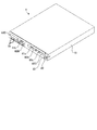
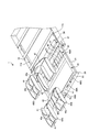
図1〜図4は、本発明の実施の形態1である硬貨収納装置を示したものである。ここで例示する硬貨収納装置1は、図には明示していないが、POSレジスタに接続された釣銭機に補充する棒状硬貨を準備金として収納するものである。棒状硬貨とは、図3に示すように、同一金種の硬貨を予め設定した枚数だけ積層して包装し、1つの取扱単位として構成したものである。本実施の形態1では、1円硬貨、5円硬貨、10円硬貨、50円硬貨、100円硬貨、500円硬貨をそれぞれ50枚ずつ包装した棒状硬貨BCと、500円硬貨を20枚包装した長さの短い棒状硬貨BC′とを収納対象とする硬貨収納装置1を例示している。
(Embodiment 1)
1 to 4 show a coin storage device according to Embodiment 1 of the present invention. The coin storage device 1 illustrated here stores, as a reserve, a bar-shaped coin that is replenished to a change machine connected to a POS register, although not shown in the figure. As shown in FIG. 3, the bar-shaped coin is formed by stacking and packaging a predetermined number of coins of the same denomination as one handling unit. In the first embodiment, a bar-shaped coin BC in which 50 pieces of 1-yen coins, 5-yen coins, 10-yen coins, 50-yen coins, 100-yen coins, and 500-yen coins are wrapped, and 20 500-yen coins are wrapped. The coin storage apparatus 1 which stores rod-shaped coin BC 'with a short length is illustrated.

図1〜図4からも明らかなように、硬貨収納装置1は、装置本体10と、装置本体10の内部に配設した収納箱20とを備えている。装置本体10は、前面が開口した直方体状を成すものである。この装置本体10には、その内部に左右一対の本体側ガイド部材11a,11bが配設してある。正面向かって左側に設けた本体側ガイド部材11aは、装置本体10の側壁内面に取り付けてある。一方、正面向かって右側に設けた本体側ガイド部材11bは、装置本体10の側壁内面から間隔を確保した位置に取り付けてある。   As apparent from FIGS. 1 to 4, the coin storage device 1 includes a device main body 10 and a storage box 20 disposed inside the device main body 10. The apparatus main body 10 has a rectangular parallelepiped shape with an open front surface. The apparatus main body 10 has a pair of left and right main body side guide members 11a and 11b disposed therein. The main body side guide member 11 a provided on the left side when facing the front is attached to the inner surface of the side wall of the apparatus main body 10. On the other hand, the main body side guide member 11 b provided on the right side when viewed from the front is attached to a position where an interval is secured from the inner surface of the side wall of the apparatus main body 10.

収納箱20は、装置本体10に設けた一対の本体側ガイド部材11a,11bの間に挿入可能となる大きさに構成した箱体であり、上面全面が開口した直方体状を成している。この収納箱20には、両側壁の外面にそれぞれ箱側ガイド部材21(図においては一方のみを示す)が配設してある。箱側ガイド部材21は、収納箱20の外面から外方に向けて突出したものである。それぞれの箱側ガイド部材21は、装置本体10に設けた本体側ガイド部材11a,11bに摺動自在に当接することにより、収納箱20を装置本体10の前面に設けた開口から引き出し可能に支持している。   The storage box 20 is a box that has a size that can be inserted between a pair of main body side guide members 11 a and 11 b provided in the apparatus main body 10, and has a rectangular parallelepiped shape whose entire upper surface is open. The storage box 20 is provided with box side guide members 21 (only one is shown in the figure) on the outer surfaces of both side walls. The box side guide member 21 protrudes outward from the outer surface of the storage box 20. Each box-side guide member 21 is slidably brought into contact with main-body-side guide members 11 a and 11 b provided on the apparatus main body 10, thereby supporting the storage box 20 so that it can be pulled out from an opening provided on the front surface of the apparatus main body 10. doing.

装置本体10と収納箱20との間には、停止機構30が設けてある。停止機構30は、装置本体10に対する収納箱20の移動を制限するものである。本実施の形態1では、装置本体10に可動ストッパ片31を設ける一方、収納箱20に前後一対の係止片32,33を設けることによって停止機構30を構成している。   A stop mechanism 30 is provided between the apparatus main body 10 and the storage box 20. The stop mechanism 30 restricts the movement of the storage box 20 relative to the apparatus main body 10. In the first embodiment, the stop mechanism 30 is configured by providing the movable stopper piece 31 in the apparatus main body 10 and providing a pair of front and rear locking pieces 32 and 33 in the storage box 20.

可動ストッパ片31は、図4に示すように、装置本体10に設けたストッパ本体34に軸35を介して揺動可能に支持させてあり、収納箱20の一方の側壁外面に対して近接離反移動することが可能である。可動ストッパ片31の先端部は、収納箱20に近接する方向に向けて略直角に屈曲して係合部31aを構成している。   As shown in FIG. 4, the movable stopper piece 31 is supported by a stopper main body 34 provided on the apparatus main body 10 so as to be swingable via a shaft 35, and is moved close to and away from one side wall outer surface of the storage box 20. It is possible to move. The distal end portion of the movable stopper piece 31 is bent at a substantially right angle in the direction approaching the storage box 20 to constitute the engaging portion 31a.

ストッパ本体34には、押圧バネ36及び電磁ソレノイド37が設けてある。押圧バネ36は、ストッパ本体34と可動ストッパ片31との間に設けたもので、可動ストッパ片31の係合部31aを常時装置本体10の側壁外面に当接させるように押圧している。電磁ソレノイド37は、励磁した場合に押圧バネ36の押圧力に抗して可動ストッパ片31を吸着し、係合部31aを装置本体10の側壁外面から離隔させるものである。   The stopper body 34 is provided with a pressing spring 36 and an electromagnetic solenoid 37. The pressing spring 36 is provided between the stopper main body 34 and the movable stopper piece 31 and presses the engaging portion 31a of the movable stopper piece 31 so as to always contact the outer surface of the side wall of the apparatus main body 10. The electromagnetic solenoid 37 adsorbs the movable stopper piece 31 against the pressing force of the pressing spring 36 when excited, and separates the engaging portion 31 a from the outer surface of the side wall of the apparatus main body 10.

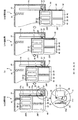
収納箱20に設けた一対の係止片32,33は、それぞれ側壁外面から外方に向けて突設したもので、前方に向けて漸次突出量が多くなるように傾斜し、かつ最も前方となる部位に係止面32a,33aを構成している。収納箱20の前側に設けた係止片32は、図4の(a)に示すように、装置本体10に対して収納箱20を全閉状態に配置した場合、先端の係止面32aが可動ストッパ片31の係合部31aに係合することにより、収納箱20の前方への移動を阻止するように機能する。収納箱20の後側に設けた係止片33は、図4の(c)に示すように、収納箱20を装置本体10から引き出した場合に収納箱20の前半部分20Fが装置本体10から外部に露出し、かつ収納箱20の後半部分20Rが装置本体10に覆われた位置において可動ストッパ片31の係合部31aに係合し、収納箱20の前方への移動を阻止するように機能する。   The pair of locking pieces 32 and 33 provided in the storage box 20 are each provided so as to protrude outward from the outer surface of the side wall, and are inclined so that the amount of protrusion gradually increases toward the front, The engaging surfaces 32a and 33a are formed in the parts. As shown in FIG. 4A, the locking piece 32 provided on the front side of the storage box 20 has a locking surface 32a at the tip when the storage box 20 is placed in a fully closed state with respect to the apparatus main body 10. By engaging with the engaging portion 31 a of the movable stopper piece 31, it functions to prevent the storage box 20 from moving forward. As shown in FIG. 4C, the locking piece 33 provided on the rear side of the storage box 20 is such that when the storage box 20 is pulled out from the apparatus main body 10, the front half portion 20 </ b> F of the storage box 20 is separated from the apparatus main body 10. It is exposed to the outside, and the rear half portion 20R of the storage box 20 is engaged with the engaging portion 31a of the movable stopper piece 31 at a position where it is covered by the apparatus main body 10, and the forward movement of the storage box 20 is prevented. Function.

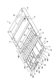
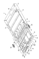
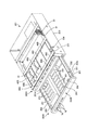
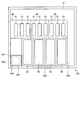
収納箱20の内部には、図2及び図3に示すように、複数の収納容器40及び複数の硬貨収納トレイ50が配設してある。収納容器40は、互いの同一の外形寸法を有したもので、収納箱20の内部において手前側に位置する前半部分20Fに左右に並べた状態で着脱可能に配置してある。本実施の形態1では、図2〜図4に示すように、収納箱20の前半部分20Fに左右方向に沿って4つ並設することができ、かつ収納箱20の後側に設けた係止片33が可動ストッパ片31の係合部31aに係合した場合に外部に露出するように収納容器40の寸法が設定してある。   As shown in FIGS. 2 and 3, a plurality of storage containers 40 and a plurality of coin storage trays 50 are disposed inside the storage box 20. The storage containers 40 have the same external dimensions, and are detachably arranged in a state where they are arranged side by side on the front half portion 20F located on the near side inside the storage box 20. In the first embodiment, as shown in FIGS. 2 to 4, the front half portion 20 </ b> F of the storage box 20 can be juxtaposed along the left-right direction and provided on the rear side of the storage box 20. The dimensions of the storage container 40 are set so that the stopper piece 33 is exposed to the outside when engaged with the engaging portion 31 a of the movable stopper piece 31.

正面向かって左側に配置した3つの収納容器40は、個々の内部を前後に仕切る仕切壁40aを有するとともに、前後の収納空間をさらに左右二分割する仕切板41が着脱可能に設けられたものである。仕切壁40aや仕切板41によって内部が複数の収納空間に区画された収納容器40(以下、収納容器を区別する場合に「小物収納容器40S」という)は、例えばバラ硬貨や変形硬貨等、縦横寸法が比較的小さい有価媒体、あるいはクリップ、印鑑、収入印紙等のように縦横寸法が比較的小さい小型物品を収納するのに好適である。   The three storage containers 40 arranged on the left side when viewed from the front have partition walls 40a for partitioning the interiors of the interior and the exterior, and a partition plate 41 that further divides the front and rear storage spaces into left and right parts is detachably provided. is there. A storage container 40 whose interior is partitioned into a plurality of storage spaces by the partition wall 40a and the partition plate 41 (hereinafter referred to as “small storage container 40S” when distinguishing between storage containers) is, for example, a rose coin or a deformed coin. It is suitable for storing valuable media having relatively small dimensions, or small articles having relatively small vertical and horizontal dimensions such as clips, seals, and revenue stamps.

これに対して正面向かって右側に配置した収納容器40は、内部を一つの収納空間として用いるものである。内部を一つの収納空間として用いる収納容器(以下、収納容器を区別する場合に「大物収納容器40B」という)は、例えばビール券やその他の商品券、あるいは紙幣等、縦横寸法が比較的大きな有価媒体、あるいは筆記用具やハサミ、ステープラ等のように縦横寸法が比較的大きな大型物品を収納するのに好適である。   On the other hand, the storage container 40 disposed on the right side of the front uses the inside as one storage space. Storage containers that use the interior as a single storage space (hereinafter referred to as “large storage container 40B” when distinguishing storage containers) are valuable, such as beer tickets, other gift certificates, or banknotes, with relatively large vertical and horizontal dimensions. It is suitable for storing a medium or a large article having comparatively large vertical and horizontal dimensions such as a writing instrument, scissors, a stapler.

尚、これら小物収納容器40S及び大物収納容器40Bには、それぞれ上面の開口を覆うための蓋体42を着脱可能に配設することが可能である。この蓋体42は、図には明示していないが、それぞれの収納容器40に対して開口を覆うように配置した場合にも、後述する収納箱20の前壁22に設けた装着孔22aに対応する部位を常時開放するものである。   Note that a lid 42 for covering the opening on the upper surface of each of the small article storage container 40S and the large article storage container 40B can be detachably disposed. Although not clearly shown in the drawing, the lid 42 is formed in a mounting hole 22a provided on the front wall 22 of the storage box 20 described later even when it is disposed so as to cover the opening of each storage container 40. The corresponding part is always opened.

図6に示すように、収納箱20の前壁22において収納容器40に対応する部位には、それぞれ入口ブロック60A,60B,60C,60Dが配設してある。入口ブロック60A,60B,60C,60Dは、互いに同一の外形寸法に形成したブロック状部材であり、前壁22に設けた4つの矩形状を成す装着孔22aに対してそれぞれが着脱可能である。これらの入口ブロックのうちの3つ60A,60B,60Cには、互いに異なる形態の媒体受入口61が形成してある。本実施の形態1では、バラ硬貨に対応したバラ硬貨投入口61aを有する入口ブロック60A、変形硬貨に対応した変形硬貨投入口61bを有する入口ブロック60B、商品券や紙幣に対応した紙葉類投入口61cを有する入口ブロック60Cが用意してある。バラ硬貨投入口61aは、硬貨を1枚ずつ挿入することのできる寸法に形成した横長の開口であり、入口ブロック60Aの中央部に形成してある。変形硬貨投入口61bは、バラ硬貨投入口61aよりも上下方向の寸法を大きく構成した横長の開口であり、入口ブロック60Bの中央部に形成してある。紙葉類投入口61cは、紙葉を挿入することのできる寸法に形成した横長の開口であり、入口ブロック60Cの幅方向いっぱいに形成してある。残りの1つの入口ブロック60Dは、前壁22の装着孔22aを単に閉塞するためのものである。本実施の形態1では、紙葉類投入口61cを有した入口ブロック60Cを正面向かって最も右側に位置する前壁22の装着孔22aに装着し、バラ硬貨投入口61aを有した入口ブロック60Aを右から2番目の装着孔22aに装着し、変形硬貨投入口61bを有した入口ブロック60Bを右から3番目の装着孔22aに装着し、媒体受入口61の無い入口ブロック60Dを正面向かって最も左側に位置する前壁22の装着孔22aに装着してある。   As shown in FIG. 6, inlet blocks 60 </ b> A, 60 </ b> B, 60 </ b> C, and 60 </ b> D are disposed at portions corresponding to the storage container 40 on the front wall 22 of the storage box 20. The inlet blocks 60A, 60B, 60C, and 60D are block-shaped members that are formed to have the same outer dimensions, and can be attached to and detached from the four mounting holes 22a formed in the front wall 22, respectively. Three of these inlet blocks 60A, 60B and 60C are formed with medium receiving ports 61 having different forms. In the first embodiment, an inlet block 60A having a rose coin slot 61a corresponding to a loose coin, an inlet block 60B having a deformed coin slot 61b corresponding to a deformed coin, and a paper sheet corresponding to a gift certificate or banknote. An inlet block 60C having a mouth 61c is prepared. The loose coin slot 61a is a horizontally long opening formed to have a size that allows coins to be inserted one by one, and is formed at the center of the inlet block 60A. The deformed coin slot 61b is a horizontally long opening having a larger vertical dimension than the loose coin slot 61a, and is formed at the center of the inlet block 60B. The paper sheet input port 61c is a horizontally long opening formed to have a size into which a paper sheet can be inserted, and is formed to fill the width direction of the inlet block 60C. The remaining one inlet block 60D is merely for closing the mounting hole 22a of the front wall 22. In the first embodiment, the inlet block 60C having the paper sheet insertion slot 61c is mounted in the mounting hole 22a of the front wall 22 located on the rightmost side in the front, and the inlet block 60A having the loose coin slot 61a. Is mounted in the second mounting hole 22a from the right, the inlet block 60B having the deformed coin slot 61b is mounted in the third mounting hole 22a from the right, and the inlet block 60D without the medium receiving port 61 is faced to the front. It is mounted in the mounting hole 22a of the front wall 22 located on the leftmost side.

また、収納箱20の前壁22において入口ブロック60A,60B,60C,60Dよりも下方となる部位には、複数のLED(light emitting diode)70が配設してある。これらのLED70は、後述する硬貨収納トレイ50の硬貨収納凹部51に棒状硬貨BC,BC′が収納されているか否かを点灯表示するためのもので、棒状硬貨BC,BC′の種類に応じた数だけ用意してある。   In addition, a plurality of LEDs (light emitting diodes) 70 are disposed on the front wall 22 of the storage box 20 below the entrance blocks 60A, 60B, 60C, 60D. These LEDs 70 are used to illuminate and display whether or not the bar-shaped coins BC and BC ′ are stored in the coin storage recess 51 of the coin storage tray 50, which will be described later, depending on the type of the bar-shaped coins BC and BC ′. There are as many as available.

尚、図中の符号45は、中央に位置する2つの収納容器40の間に配設した隙間調整用部材45である。本実施の形態1では、この隙間調整用部材45の上面に前後方向寸法に対して左右方向寸法の小さい収納空間45aが構成してある。この隙間調整用部材45に設けた収納空間45aは、例えばボールペンや鉛筆等の筆記用具のように、細長い物品を収納するのに好適である。   Incidentally, reference numeral 45 in the drawing denotes a gap adjusting member 45 disposed between two storage containers 40 located in the center. In the first embodiment, a storage space 45a having a small lateral dimension with respect to the longitudinal dimension is formed on the upper surface of the gap adjusting member 45. The storage space 45a provided in the gap adjusting member 45 is suitable for storing elongate articles such as a writing instrument such as a ballpoint pen or a pencil.

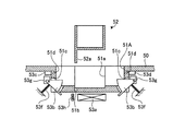
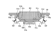
硬貨収納トレイ50は、それぞれ矩形のプレート状を成すもので、収納箱20の内部において奥方側に位置する後半部分20Rに左右に並べた状態で配置してある。本実施の形態1では、3つの硬貨収納トレイ50が収納箱20の内部に並設してある。これら硬貨収納トレイ50には、個々の上面に複数の硬貨収納凹部51が設けてある。硬貨収納凹部51は、図7〜図10に示すように、棒状硬貨BCを横倒しの状態で収納するための半円筒状の凹所であり、軸心が収納箱20の前後方向に沿う状態で個々の硬貨収納トレイ50に4つずつ形成してある。   The coin storage trays 50 each have a rectangular plate shape, and are arranged side by side in a rear half portion 20R located on the back side inside the storage box 20. In the first embodiment, three coin storage trays 50 are juxtaposed inside the storage box 20. These coin storage trays 50 are provided with a plurality of coin storage recesses 51 on each upper surface. As shown in FIGS. 7 to 10, the coin storage recess 51 is a semi-cylindrical recess for storing the bar-shaped coin BC in a lying state, and the axial center is in a state along the front-rear direction of the storage box 20. Four each coin storage tray 50 is formed.

このうち、正面向かって左側に配置した硬貨収納トレイ50には、最も左側に位置する硬貨収納凹部51(以下、その他の硬貨収納凹部と区別する場合に「500円硬貨収納凹部51A」という)の中央部にケース収納部51aが付設してあるとともに、このケース収納部51aに嵌合される硬貨収納ケース52が用意してある。ケース収納部51aは、500円硬貨収納凹部51Aよりも内径の大きな半円筒状の凹所であり、内底部に突起貫通孔51bを有している。硬貨収納ケース52は、500円硬貨を20枚包装した長さの短い棒状硬貨BC′を収納するための半円筒状に形成した容器であり、ケース収納部51aに嵌合する大きさに形成してある。硬貨収納ケース52には、識別用突起52aが設けてある。識別用突起52aは、硬貨収納ケース52の外周面から径外方向に向けて突設した舌片状部分である。この識別用突起52aは、硬貨収納ケース52をケース収納部51aに嵌合させた場合に突起貫通孔51bを介して硬貨収納トレイ50の裏面に突出されるだけの長さを有している。   Among these, the coin storage tray 50 disposed on the left side of the front has a coin storage recess 51 located on the leftmost side (hereinafter referred to as “500-yen coin storage recess 51A” when distinguished from other coin storage recesses). A case storage portion 51a is attached to the center portion, and a coin storage case 52 to be fitted into the case storage portion 51a is prepared. The case storage 51a is a semi-cylindrical recess having an inner diameter larger than that of the 500-yen coin storage recess 51A, and has a protruding through hole 51b on the inner bottom. The coin storage case 52 is a container formed in a semi-cylindrical shape for storing a short bar-shaped coin BC ′ in which 20 pieces of 500 yen coins are packaged, and is formed in a size that fits into the case storage portion 51a. It is. The coin storage case 52 is provided with an identification protrusion 52a. The identification protrusion 52 a is a tongue-like portion protruding from the outer peripheral surface of the coin storage case 52 in the radially outward direction. The identification protrusion 52a has a length that can be projected to the back surface of the coin storage tray 50 via the protrusion through hole 51b when the coin storage case 52 is fitted to the case storage portion 51a.

それぞれの硬貨収納凹部51には、検出部53として、磁気コイル53a、一対の当接レバー53b、投光素子53c及び受光素子53dが設けてある。磁気コイル53aは、硬貨収納凹部51に棒状硬貨BCが収納された場合に磁気インピーダンスが変化するもので、硬貨収納トレイ50の裏面において硬貨収納凹部51のほぼ中央となる部位に配設してある。それぞれの磁気コイル53aには、コイル検出回路53e(図11参照)が付設してある。コイル検出回路53eは、磁気コイル53aの磁気インピーダンスが変化した場合に検出信号を出力するものである。   Each coin storage recess 51 is provided with a magnetic coil 53 a, a pair of contact levers 53 b, a light projecting element 53 c, and a light receiving element 53 d as the detection unit 53. The magnetic coil 53a changes in magnetic impedance when the bar-shaped coin BC is stored in the coin storage recess 51, and is disposed at a portion that is substantially at the center of the coin storage recess 51 on the back surface of the coin storage tray 50. . A coil detection circuit 53e (see FIG. 11) is attached to each magnetic coil 53a. The coil detection circuit 53e outputs a detection signal when the magnetic impedance of the magnetic coil 53a changes.

一対の当接レバー53bは、硬貨収納凹部51の両端に形成した開口51cから内部に出没するように揺動可能に配設したものである。個々の当接レバー53bには、それぞれの先端部が開口51cから内部に突出するように押圧するレバーバネ53fが設けてある。これらの当接レバー53bは、硬貨収納凹部51に50枚包装した棒状硬貨BCが収納された場合にだけ両者が共に硬貨収納凹部51から退避移動するように構成してある。それぞれの当接レバー53bには、レバーセンサ53gが付設してある。レバーセンサ53gは、当接レバー53bの先端部が硬貨収納凹部51に突出した状態にあるか否かを個別に検出するものである。   The pair of contact levers 53b are disposed so as to be swingable so as to protrude into and out of openings 51c formed at both ends of the coin storage recess 51. Each contact lever 53b is provided with a lever spring 53f that presses the tip of each contact lever 53b so as to protrude from the opening 51c. These contact levers 53b are configured such that both of them retract from the coin storage recess 51 only when 50 bar-shaped coins BC wrapped in the coin storage recess 51 are stored. Each contact lever 53b is provided with a lever sensor 53g. The lever sensor 53g individually detects whether or not the tip of the contact lever 53b protrudes into the coin storage recess 51.

投光素子53c及び受光素子53dは、硬貨収納凹部51に形成したスリット51dを介して互いに対向するように配置したもので、投光素子53cから照射した光が受光素子53dに入射した場合に検出信号を出力する。   The light projecting element 53c and the light receiving element 53d are arranged so as to face each other through a slit 51d formed in the coin housing recess 51, and are detected when light emitted from the light projecting element 53c enters the light receiving element 53d. Output a signal.

さらに、500円硬貨収納凹部51Aには、突起センサ53hが設けてある。突起センサ53hは、突起貫通孔51bを介して硬貨収納ケース52の識別用突起52aが硬貨収納トレイ50の裏面に突出された場合に検出信号を出力するものである。   Further, a protrusion sensor 53h is provided in the 500 yen coin storage recess 51A. The protrusion sensor 53h outputs a detection signal when the identification protrusion 52a of the coin storage case 52 protrudes from the back surface of the coin storage tray 50 through the protrusion through hole 51b.

図11は、棒状硬貨BC,BC′の検出制御系を示すブロック図である。図11に示す検出制御部54は、硬貨収納トレイ50に設けた各硬貨収納凹部51の検出部53から検出信号が与えられた場合に硬貨収納凹部51に棒状硬貨BC,BC′が収納されているか否かを判断するものである。例えば、図8−1に示すように、レバーセンサ53gによって当接レバー53bのそれぞれの先端部が硬貨収納凹部51に突出されていることが検出され、かつ受光素子53dに対して投光素子53cからの入射光があり、さらにコイル検出回路53eによって検出される磁気コイル53aの磁気インピーダンスに変化がない場合、検出制御部54は、硬貨収納凹部51に棒状硬貨BC,BC′が収納されていないと判断する。硬貨収納凹部51に棒状硬貨BC,BC′が収納されていないと判断した検出制御部54は、該当する金種に対応したLED70を消灯した状態に維持する処理を行う。   FIG. 11 is a block diagram showing a detection control system for the bar-shaped coins BC and BC ′. The detection control unit 54 shown in FIG. 11 stores the bar-shaped coins BC and BC ′ in the coin storage recess 51 when a detection signal is given from the detection unit 53 of each coin storage recess 51 provided in the coin storage tray 50. Whether or not there is. For example, as shown in FIG. 8A, it is detected by the lever sensor 53g that each tip of the abutment lever 53b protrudes into the coin housing recess 51, and the light projecting element 53c with respect to the light receiving element 53d. In the case where there is no change in the magnetic impedance of the magnetic coil 53a detected by the coil detection circuit 53e, the detection control unit 54 does not store the bar-shaped coins BC, BC ′ in the coin storage recess 51. Judge. The detection control unit 54 that has determined that the bar-shaped coins BC and BC ′ are not stored in the coin storage recess 51 performs a process of keeping the LED 70 corresponding to the corresponding denomination in an unlit state.

これに対してレバーセンサ53gによって当接レバー53bがいずれも硬貨収納凹部51から退避されていることが検出され、かつ受光素子53dに対して投光素子53cからの入射光がなく、さらにコイル検出回路53eによって検出される磁気コイル53aの磁気インピーダンスに変化が生じた場合、検出制御部54は、硬貨収納凹部51に50枚包装した正規の棒状硬貨BCが収納されていると判断する。この場合、検出制御部54は、該当する硬貨の種類に対応したLED70を点灯する処理を行う。従って、収納箱20が全閉状態に維持された状態にあっても、収納箱20の内部に棒状硬貨BCが収納されているか否かを判断することが可能となる。   On the other hand, it is detected by the lever sensor 53g that all of the contact levers 53b are retracted from the coin storage recess 51, and there is no incident light from the light projecting element 53c with respect to the light receiving element 53d. When a change occurs in the magnetic impedance of the magnetic coil 53a detected by the circuit 53e, the detection control unit 54 determines that 50 regular bar-shaped coins BC wrapped in the coin storage recess 51 are stored. In this case, the detection control part 54 performs the process which lights LED70 corresponding to the kind of applicable coin. Therefore, even when the storage box 20 is maintained in the fully closed state, it is possible to determine whether or not the bar-shaped coin BC is stored in the storage box 20.

尚、レバーセンサ53gによって少なくとも一方の当接レバー53bが硬貨収納凹部51から退避されていることが検出され、かつ受光素子53dに対して投光素子53cからの入射光がなく、コイル検出回路53eによって検出される磁気コイル53aの磁気インピーダンスに変化が生じた場合、検出制御部54は、硬貨収納凹部51に異物が収納されていると判断する。例えば、50枚に満たない棒状硬貨BCが硬貨収納凹部51に収納された場合、上述した結果となる。この場合、検出制御部54は、例えば外部に対してエラー出力し、LED70を点滅表示する等して硬貨収納凹部51に異物が収納されていることを報知する。   The lever sensor 53g detects that at least one of the contact levers 53b is retracted from the coin housing recess 51, and there is no incident light from the light projecting element 53c on the light receiving element 53d, and the coil detection circuit 53e. When a change occurs in the magnetic impedance of the magnetic coil 53a detected by the detection, the detection control unit 54 determines that a foreign object is stored in the coin storage recess 51. For example, when less than 50 stick-shaped coins BC are stored in the coin storage recess 51, the above-described result is obtained. In this case, for example, the detection control unit 54 outputs an error to the outside, and notifies that the foreign matter is stored in the coin storage recess 51 by blinking the LED 70 or the like.

但し、500円硬貨収納凹部51Aにおいては、レバーセンサ53gによって少なくとも一方の当接レバー53bが退避されていることが検出され、かつ受光素子53dに対して投光素子53cからの入射光がなく、コイル検出回路53eによって磁気コイル53aの磁気インピーダンス変化を検出した場合、以下の処理を実施し、500円硬貨を20枚包装した棒状硬貨BC′が収納されているか否かの判断を行う。すなわち、少なくとも一方の当接レバー53bが退避されていることが検出された場合、検出制御部54は、突起センサ53hによって硬貨収納ケース52の識別用突起52aが硬貨収納トレイ50の裏面に突出されているか否かを判断する。突起センサ53hによって識別用突起52aを検出した場合には、500円硬貨収納凹部51Aに硬貨収納ケース52が嵌合された状態にある。従って、検出制御部54は、硬貨収納ケース52に20枚包装された500円の棒状硬貨BC′が収納されていると判断し、該当するLED70を点灯する処理を行う。これにより、500円硬貨収納凹部51Aにおいては、50枚包装された棒状硬貨BCが収納されているか否かに加え、20枚包装された棒状硬貨BC′が収納されているか否かを判断することができるようになる。   However, in the 500-yen coin storing recess 51A, it is detected by the lever sensor 53g that at least one contact lever 53b is retracted, and there is no incident light from the light projecting element 53c with respect to the light receiving element 53d. When the magnetic impedance change of the magnetic coil 53a is detected by the coil detection circuit 53e, the following processing is performed to determine whether or not the bar-shaped coin BC ′ in which 20 pieces of 500-yen coins are packed is stored. That is, when it is detected that at least one of the contact levers 53b is retracted, the detection control unit 54 causes the projection sensor 53h to project the identification projection 52a of the coin storage case 52 to the back surface of the coin storage tray 50. Judge whether or not. When the identification protrusion 52a is detected by the protrusion sensor 53h, the coin storage case 52 is fitted in the 500-yen coin storage recess 51A. Therefore, the detection control unit 54 determines that the 500-yen bar-shaped coin BC ′ packaged in the coin storage case 52 is stored, and performs a process of lighting the corresponding LED 70. Thereby, in the 500 yen coin storage recess 51A, in addition to whether or not 50 packed bar-shaped coins BC are stored, it is determined whether or not 20 packed bar-shaped coins BC 'are stored. Will be able to.

尚、図中の符号80は、収納箱の内部に設けられた電源である。   Note that reference numeral 80 in the figure denotes a power source provided inside the storage box.

上記のように構成した硬貨収納装置1は、図には明示していないが、例えば装置本体10の上面に釣銭機が載置され、さらにその上面にPOSレジスタが載置された状態でスーパーマーケットやコンビニエンスストアに設置される。硬貨収納トレイ50の各硬貨収納凹部51には、準備金として所望金種の棒状硬貨BC,BC′が予め収納された状態にあり、上述した検出制御部54の制御により、該当するLED70が点灯した状態にある。収納箱20の前半部分20Fに配設された収納容器40には、バラ硬貨、筆記用具、ハサミ、ステープラ、印鑑、収入印紙等々、レジスタ作業において必要となる物品を予め収納させておく。   The coin storage device 1 configured as described above is not clearly shown in the drawing, but for example, a supermarket or the like with a change machine mounted on the top surface of the device body 10 and a POS register mounted on the top surface. Installed at convenience stores. In each coin storage recess 51 of the coin storage tray 50, rod-shaped coins BC and BC ′ of a desired denomination are stored in advance as reserves, and the corresponding LED 70 is lit by the control of the detection control unit 54 described above. Is in a state. In the storage container 40 disposed in the first half portion 20F of the storage box 20, articles necessary for registering work such as rose coins, writing instruments, scissors, staplers, seals, revenue stamps, and the like are stored in advance.

店舗が開店すると、釣銭機においては、POSレジスタとの間において適宜情報交換を行い、買い物客からの入金額に対して商品の購入金額が小さい場合、その差額を釣銭として払い出す処理を行うことになる。硬貨収納装置1においては、電磁ソレノイド37が消磁された状態のままであり、図1及び図4の(a)に示すように、押圧バネ36の押圧力によって可動ストッパ片31の係合部31aが収納箱20の前側に設けた係止片32と係合した状態に維持されるため、外部から収納箱20を引き出すことが困難な状態にある。   When the store opens, the change machine exchanges information with the POS register as appropriate, and if the purchase amount of the product is small relative to the amount received from the shopper, the difference is paid out as change. become. In the coin storage device 1, the electromagnetic solenoid 37 remains in a demagnetized state, and the engaging portion 31a of the movable stopper piece 31 is pressed by the pressing force of the pressing spring 36 as shown in FIGS. Is maintained in a state of being engaged with a locking piece 32 provided on the front side of the storage box 20, it is difficult to pull out the storage box 20 from the outside.

ここで、買い物客から商品券が手渡された場合、レジスタ担当者は、これを紙葉類投入口61cから収納箱20の内部に投入すれば、商品券を大物収納容器40Bに格納することができる。同様に、買い物客から手渡された紙幣や硬貨が破損していたり、変形していたりした場合には、該当する媒体受入口61から内部に投入すれば、破損紙幣を大物収納容器40Bに格納することができ、変形硬貨を小物収納容器40Sに格納することができる。上述した収納容器40への格納操作は、いずれも装置本体10に対して収納箱20を引き出す必要がない。従って、レジスタ作業の容易化を図ることができるばかりでなく、収納箱20が全閉状態に維持される結果、棒状硬貨BC,BC′が外部に晒される事態を招来することがなく、棒状硬貨BC,BC′の管理上及びセキュリティ上、きわめて有利となる。   Here, when the gift certificate is handed over from the shopper, the register person in charge can store the gift certificate in the large container 40B by inserting it into the storage box 20 through the paper sheet insertion slot 61c. it can. Similarly, when a banknote or a coin handed over by a shopper is damaged or deformed, the damaged banknote is stored in the large container 40B by being inserted into the corresponding medium receiving port 61. The deformed coin can be stored in the accessory storage container 40S. In any of the above-described storage operations in the storage container 40, it is not necessary to pull out the storage box 20 from the apparatus main body 10. Accordingly, not only can the register work be facilitated, but the storage box 20 is maintained in a fully closed state, so that the bar coins BC and BC ′ are not exposed to the outside, and the bar coins are not exposed. This is very advantageous in terms of management and security of BC and BC ′.

一方、領収証に対して収入印紙を貼り付け、これに印鑑を押す等の作業が必要となった場合、レジスタ担当者は、POSレジスタを介して収納箱20を開放する操作を一度実施すれば良い。すなわち、POSレジスタからの制御信号によって電磁ソレノイド37が一旦励磁されると、可動ストッパ片31が吸着されるため、収納箱20の前側に設けた係止片32との係合状態が解除される。その後、可動ストッパ片31は、再び押圧バネ36の押圧力によって電磁ソレノイド37から離隔し、収納箱20の側壁外面に当接された状態となる。   On the other hand, if it is necessary to affix an income stamp on the receipt and press a seal on the receipt, the person in charge of the register only needs to perform an operation of opening the storage box 20 via the POS register. . That is, once the electromagnetic solenoid 37 is excited by the control signal from the POS register, the movable stopper piece 31 is attracted, so that the engagement state with the locking piece 32 provided on the front side of the storage box 20 is released. . Thereafter, the movable stopper piece 31 is again separated from the electromagnetic solenoid 37 by the pressing force of the pressing spring 36 and is in contact with the outer surface of the side wall of the storage box 20.

この間、可動ストッパ片31と係止片32との係合状態が解除された収納箱20は、装置本体10との間に設けた引き出しスプリング81の押圧力によって手前側に押し出されることになり、収納箱20の後側に設けた係止片33が可動ストッパ片31の係合部31aに係合するまで引き出してその内部を外部に露出することが可能である。つまり、図2及び図4の(c)に示すように、収納箱20の前半部分20Fが外部に露出されることになる。これにより、POSレジスタから離れることなく収納容器40に収納させた収入印紙や印鑑を取り出して上述のレジスタ作業を迅速に実施することができるようになり、その作業性を向上させることが可能となる。しかも、上述のレジスタ作業を実施している間においても、棒状硬貨BC,BC′を収納した硬貨収納トレイ50が外部に露出することはなく、棒状硬貨BC,BC′の管理上及びセキュリティ上、きわめて有利となる。尚、上述の中途位置から収納箱20を装置本体10に対して押し込めば、係止片32の傾斜作用によって可動ストッパ片31が適宜移動し、係止片32よりも前側に位置した状態で収納箱20の側壁外面に当接された状態となる。従って、POSレジスタへの操作を伴うことなく収納箱20を全閉状態に復帰させることができる。   During this time, the storage box 20 in which the movable stopper piece 31 and the locking piece 32 are disengaged is pushed forward by the pressing force of the pull-out spring 81 provided between the apparatus main body 10 and the storage box 20. The engaging piece 33 provided on the rear side of the storage box 20 can be pulled out until it engages with the engaging portion 31a of the movable stopper piece 31, and the inside thereof can be exposed to the outside. That is, as shown in FIG. 2 and FIG. 4C, the front half portion 20F of the storage box 20 is exposed to the outside. As a result, it is possible to take out the revenue stamps and seals stored in the storage container 40 without leaving the POS register, and to quickly carry out the register operation described above, thereby improving the workability. . Moreover, the coin storage tray 50 in which the bar-shaped coins BC and BC ′ are stored is not exposed to the outside even during the above-described register operation, and for the management and security of the bar-shaped coins BC and BC ′, Very advantageous. If the storage box 20 is pushed into the apparatus main body 10 from the midway position described above, the movable stopper piece 31 is appropriately moved by the tilting action of the locking piece 32 and stored in a state of being positioned in front of the locking piece 32. It will be in the state contact | abutted by the side wall outer surface of the box 20. FIG. Therefore, the storage box 20 can be returned to the fully closed state without an operation to the POS register.

一方、釣銭機の釣銭が不足した場合、レジスタ担当者は、POSレジスタを介して収納箱20を全開する操作を実施し、硬貨収納トレイ50に収納された棒状硬貨BC,BC′を釣銭機に補充する作業を行う。尚、レジスタ担当者が棒状硬貨BCの管理権限を有していない場合には、釣銭機の釣銭が不足した時点で管理者を呼び出し、以下の作業を行うものとする。   On the other hand, when the change of the change machine is insufficient, the register person performs the operation of fully opening the storage box 20 via the POS register, and the bar coins BC and BC ′ stored in the coin storage tray 50 are used as the change machine. Perform replenishment work. When the register person does not have the authority to manage the bar coin BC, the manager is called when the change of the change machine is insufficient, and the following operations are performed.

まず、POSレジスタを介して電磁ソレノイド37を一旦励磁させ、収納箱20の前半部分20Fを外部に露出させた状態とする。この状態からさらにPOSレジスタを介して電磁ソレノイド37を励磁させると、可動ストッパ片31の係合部31aと収納箱20の後側に設けた係止片33との係合状態が解除されることになる。この状態から収納箱20を引き出せば、これを全開状態とすることができる。すなわち、収納箱20の後半部分20Rに配置した硬貨収納トレイ50を装置本体10の外部に露出させ、それぞれの硬貨収納凹部51に収納された棒状硬貨BC,BC′から該当するものを抜き出して釣銭機に補充することができるようになる。   First, the electromagnetic solenoid 37 is once excited through the POS register so that the front half portion 20F of the storage box 20 is exposed to the outside. When the electromagnetic solenoid 37 is further excited from this state via the POS register, the engaged state between the engaging portion 31a of the movable stopper piece 31 and the locking piece 33 provided on the rear side of the storage box 20 is released. become. If the storage box 20 is pulled out from this state, it can be fully opened. That is, the coin storage tray 50 disposed in the rear half portion 20R of the storage box 20 is exposed to the outside of the apparatus body 10, and the corresponding ones are extracted from the bar-shaped coins BC and BC 'stored in the respective coin storage recesses 51. The machine can be refilled.

これにより、釣銭機自体の大型化を招来することなく、釣銭切れによる釣銭機の稼働時間低下、つまりはPOSレジスタの稼働時間低下を防止することが可能となる。しかも、収納箱20の前半部分20Fを引き出した状態からPOSレジスタに電磁ソレノイド37を励磁させる場合には、操作者の氏名入力及び管理者のみが知り得るパスワードの入力を必須とすれば、これを記録することにより、棒状硬貨BC,BC′の管理を確実に行うことが可能となる。尚、硬貨収納装置1から棒状硬貨BC,BC′が抜き出された場合には、該当する硬貨収納凹部51の検出部53を通じて検出制御部54により検出されることになり、該当するLED70が消灯した状態となる。さらに、検出制御部54の検出結果は、POSレジスタに通知され、例えば硬貨収納装置1の準備金管理に利用されることになる。   As a result, it is possible to prevent a change in the operating time of the change machine due to a change being made, that is, a reduction in the operating time of the POS register without incurring an increase in the size of the change machine itself. In addition, when the electromagnetic solenoid 37 is excited in the POS register from the state where the front half portion 20F of the storage box 20 is pulled out, if the operator's name and the password that only the administrator can know are required, By recording, it becomes possible to reliably manage the bar-shaped coins BC and BC ′. When the bar-shaped coins BC and BC ′ are extracted from the coin storage device 1, the detection control unit 54 detects the rod-shaped coins BC and BC ′, and the corresponding LED 70 is turned off. It will be in the state. Further, the detection result of the detection control unit 54 is notified to the POS register, and is used, for example, for managing the reserve of the coin storage device 1.

また、上記硬貨収納装置1では、収納箱20に対して収納容器40が着脱可能に配設してあるとともに、収納箱20の前壁22に形成した4つの装着孔22aに対して入口ブロック60A,60B,60C,60Dが着脱可能に配設してある。従って、収納箱20の内部に配置する収納容器40の順番を変更するとともに、収納容器40に応じて入口ブロック60A,60B,60C,60Dの位置を変更すれば、同じ硬貨収納装置1でありながら、内部が異なるものを構成することができるようになる。さらに、小物収納容器40Sにおいて、仕切板41を着脱することにより、収納空間の大きさを変更することができるようになる。   In the coin storage device 1, the storage container 40 is detachably disposed with respect to the storage box 20, and the inlet block 60 </ b> A is inserted into the four mounting holes 22 a formed in the front wall 22 of the storage box 20. , 60B, 60C, 60D are detachably arranged. Therefore, while changing the order of the storage containers 40 arranged inside the storage box 20 and changing the positions of the inlet blocks 60A, 60B, 60C, 60D according to the storage container 40, the same coin storage device 1 can be obtained. , It will be possible to configure something different inside. Furthermore, in the accessory storage container 40S, the size of the storage space can be changed by attaching and detaching the partition plate 41.

尚、上述した実施の形態1では、装置本体10に可動ストッパ片31を設ける一方、収納箱20に前後一対の係止片32,33を設けることによって停止機構30を構成しているが、必ずしもこれに限定されない。例えば、図12に示すように、装置本体110にガイド部材111及びローラ112を配設するとともに、収納箱120の対応する部位にガイド部材121及びローラ122を配設し、さらに双方のガイド部材111,121の適宜箇所に段部111a,121aを形成するようにしても同様の作用効果を期待することができる。   In the first embodiment described above, the stop mechanism 30 is configured by providing the movable stopper piece 31 in the apparatus main body 10 and providing the pair of front and rear locking pieces 32 and 33 in the storage box 20. It is not limited to this. For example, as shown in FIG. 12, a guide member 111 and a roller 112 are disposed in the apparatus main body 110, and a guide member 121 and a roller 122 are disposed in corresponding portions of the storage box 120. , 121 can be expected to have the same effect even if the step portions 111a, 121a are formed at appropriate positions.

すなわち、図12の(a)に示す全閉状態から装置本体110に対して収納箱120を引き出し、図12の(b)に示す中途位置においてローラ112,122がガイド部材111,121の段部111a,121aに達するように構成すれば、これらローラ112,122及び段部111a,121aの作用により、収納箱120を引き出す際の移動が一旦停止することになる。つまり、中途位置から収納箱120を図12の(c)に示す全開状態とするには、ローラ112,122がガイド部材111,121の段部111a,121aから逸脱する必要があり、単に収納箱120を引き出す場合に比べて大きな操作力が必要となる。従って、実施の形態1と同様に、収納箱120の後半部分に硬貨収納トレイを配置すれば、単に収納箱120を引き出した際には、収納箱120の後半部分が装置本体110によって覆われた状態となり、棒状硬貨BC,BC′が外部に露出することはなく、棒状硬貨BC,BC′の管理上及びセキュリティ上有利となる。   That is, the storage box 120 is pulled out of the apparatus main body 110 from the fully closed state shown in FIG. 12A, and the rollers 112 and 122 are stepped portions of the guide members 111 and 121 in the middle position shown in FIG. If it is configured to reach 111a, 121a, the movement of pulling out the storage box 120 is temporarily stopped by the action of these rollers 112, 122 and the stepped portions 111a, 121a. That is, in order to open the storage box 120 from the midway position as shown in FIG. 12 (c), the rollers 112 and 122 need to deviate from the step portions 111a and 121a of the guide members 111 and 121. Compared with the case where 120 is pulled out, a large operating force is required. Therefore, as in the first embodiment, if the coin storage tray is arranged in the second half of the storage box 120, the second half of the storage box 120 is covered by the apparatus main body 110 when the storage box 120 is simply pulled out. Thus, the bar-shaped coins BC and BC ′ are not exposed to the outside, which is advantageous in terms of management and security of the bar-shaped coins BC and BC ′.

(実施の形態2)
図13〜図15は、本発明の実施の形態2である硬貨収納装置を示したものである。ここで例示する硬貨収納装置201は、実施の形態1と同様に、POSレジスタに接続された釣銭機に補充する棒状硬貨BC,BC′を準備金として収納するもので、実施の形態1とは、収納箱の構成のみが異なっている。すなわち、実施の形態2の硬貨収納装置201では、独立した上下2つの収納体220A,220Bを備えて収納箱220を構成している。
(Embodiment 2)
13 to 15 show a coin storage device according to the second embodiment of the present invention. Similar to the first embodiment, the coin storage device 201 illustrated here stores rod-shaped coins BC and BC ′ supplemented to the change machine connected to the POS register as a reserve. Only the configuration of the storage box is different. That is, in the coin storage device 201 of the second embodiment, the storage box 220 is configured by including two independent upper and lower storage bodies 220A and 220B.

上方に配設した収納体(以下、区別する場合に「上方収納体220A」という)と下方に配設した収納体(以下、区別する場合に「下方収納体220B」という)は、上面全面が開口した直方体状を成す箱体である。これらの収納体220A,220Bは、それぞれの両側側面に設けた箱側ガイド部材221を装置本体210に設けた本体側ガイド部材211に摺動自在に当接させることにより、装置本体210の前面に設けた開口から個別に引き出し可能に配設してある。上方収納体220Aの奥行寸法及び下方収納体220Bの奥行寸法は、いずれも実施の形態1の収納箱20よりも十分に短く構成してある。   A storage body disposed above (hereinafter referred to as “upper storage body 220A” when distinguished) and a storage body disposed below (hereinafter referred to as “lower storage body 220B” when distinguished) have an entire upper surface. It is a box having a rectangular parallelepiped shape. These storage bodies 220 </ b> A and 220 </ b> B are slidably brought into contact with the main body side guide member 211 provided on the apparatus main body 210 so that the box side guide members 221 provided on the both side surfaces of the storage bodies 220 </ b> A and 220 </ b> B are placed on the front surface of the apparatus main body 210. It arrange | positions so that it can pull out separately from the provided opening. Both the depth dimension of the upper storage body 220A and the depth dimension of the lower storage body 220B are configured to be sufficiently shorter than the storage box 20 of the first embodiment.

図には明示していないが、装置本体210とそれぞれの収納体220A,220Bとの間には、それぞれ個別の停止機構230が設けてある。停止機構230は、装置本体210に対する収納体220A,220Bの移動を個別に制限するものである。本実施の形態2では、装置本体210に上下2つの可動ストッパ片(図示せず)を設ける一方、各収納体220A,220Bの前側となる部位にそれぞれ係止片232を設けることによって停止機構230を構成している。   Although not clearly shown in the figure, an individual stop mechanism 230 is provided between the apparatus main body 210 and each of the storage bodies 220A and 220B. The stop mechanism 230 individually restricts the movement of the storage bodies 220A and 220B with respect to the apparatus main body 210. In the second embodiment, the upper and lower movable stopper pieces (not shown) are provided on the apparatus main body 210, while the stop mechanism 230 is provided by providing the locking pieces 232 at the front portions of the storage bodies 220A and 220B. Is configured.

実施の形態1と同様に、停止機構230の可動ストッパ片(図示せず)は、装置本体210に設けたストッパ本体234に揺動可能に支持させてあり、対応する収納体220A,220Bの側壁外面に対して近接離反移動することが可能である。図には明示していないが、可動ストッパ片の先端部に屈曲した係合部が設けてある点、ストッパ本体234に押圧バネ(図示せず)及び電磁ソレノイド237が設けてある点も実施の形態1と同様である。   Similar to the first embodiment, the movable stopper piece (not shown) of the stop mechanism 230 is supported by the stopper main body 234 provided in the apparatus main body 210 so as to be swingable, and the side walls of the corresponding storage bodies 220A and 220B. It is possible to move close to and away from the outer surface. Although not clearly shown in the figure, there are also a point that a bent engaging portion is provided at the tip of the movable stopper piece, and a pressing spring (not shown) and an electromagnetic solenoid 237 are provided on the stopper main body 234. This is the same as the first embodiment.

収納体220A,220Bに設けた係止片232は、それぞれ側壁外面から外方に向けて突設したもので、前方に向けて漸次突出量が多くなるように傾斜し、かつ最も前方となる部位に係止面232aを構成している。それぞれ係止片232は、装置本体210に対して収納体220A,220Bを全閉状態に配置した場合、先端の係止面232aが可動ストッパ片(図示せず)の係合部に係合することにより、収納体220A,220Bの前方への移動を阻止するように機能する。本実施の形態2で示す停止機構230は、収納体220A,220Bを中途位置で停止させるための機能を有しておらず、可動ストッパ片(図示せず)の係合部と係止片232との係合状態が解除された場合、それぞれの収納体220A,220Bを全閉状態から同じ操作力でそのまま全開位置まで引き出すことが可能である。   The locking pieces 232 provided on the storage bodies 220A and 220B are each provided so as to protrude outward from the outer surface of the side wall, and are inclined so that the amount of protrusion gradually increases toward the front and the frontmost part. The latching surface 232a is configured. When each of the locking pieces 232 is disposed in the fully closed state with respect to the apparatus main body 210, the locking surface 232a at the tip engages with an engaging portion of a movable stopper piece (not shown). Thus, the storage bodies 220A and 220B function to prevent the forward movement. The stop mechanism 230 shown in the second embodiment does not have a function for stopping the storage bodies 220A and 220B in the middle position, and the engaging portion and the locking piece 232 of the movable stopper piece (not shown). When the engagement state is released, each of the storage bodies 220A and 220B can be pulled out from the fully closed state to the fully open position with the same operating force.

2つの収納体220A,220Bには、4つの収納容器40及び2つの硬貨収納トレイ250が個別に配設してある。本実施の形態2では、上方収納体220Aに4つの収納容器40が配設してある一方、下方収納体220Bに2つの硬貨収納トレイ250が配設してある。収納容器40は、実施の形態1と同様の構成を有したものであり、上方収納体220Aを全開状態に配置した場合に全てが外部に露出されることになる。硬貨収納トレイ250は、下方収納体220Bの奥行寸法に合致した長さを有する矩形のプレート状を成すもので、左右に並べた状態で配置してある。硬貨収納凹部251は、軸心が下方収納体220Bの左右方向に沿う状態で個々の硬貨収納トレイ250に複数ずつ形成してある。図からも明らかなように、正面向かって左側に配置した硬貨収納トレイ250には、最も奥方に位置する部位に実施の形態1と同様の500円硬貨収納凹部251Aが設けてあるとともに、最も手前側に位置する部位に縦横寸法が比較的小さい物品を収納するための収納空間255が構成してある。また、下方収納体220Bの正面向かって右側には、縦横寸法が比較的大きい物品を収納することのできる蓋体257付きの収納空間256が構成してある。尚、収納容器40の詳細構成並びに硬貨収納トレイ250の詳細構成及び検出制御系の構成に関しては、いずれも実施の形態1と同様であるため、同一の符号を付してそれぞれの詳細説明を省略する。   In the two storage bodies 220A and 220B, four storage containers 40 and two coin storage trays 250 are individually arranged. In the second embodiment, four storage containers 40 are disposed in the upper storage body 220A, while two coin storage trays 250 are disposed in the lower storage body 220B. The storage container 40 has the same configuration as that of the first embodiment, and when the upper storage body 220A is disposed in a fully open state, all of the storage container 40 is exposed to the outside. The coin storage tray 250 forms a rectangular plate shape having a length that matches the depth dimension of the lower storage body 220B, and is arranged in a state of being arranged side by side. A plurality of coin storage recesses 251 are formed in each coin storage tray 250 in a state where the axis is along the left-right direction of the lower storage body 220B. As is apparent from the figure, the coin storage tray 250 disposed on the left side of the front has a 500-yen coin storage recess 251A similar to that in the first embodiment at the farthest position, and is closest to the front. A storage space 255 for storing articles having relatively small vertical and horizontal dimensions is formed in a portion located on the side. In addition, a storage space 256 with a lid 257 that can store articles having relatively large vertical and horizontal dimensions is formed on the right side of the lower storage body 220B in front. The detailed configuration of the storage container 40, the detailed configuration of the coin storage tray 250, and the configuration of the detection control system are all the same as those in the first embodiment, and thus the same reference numerals are given and detailed descriptions thereof are omitted. To do.

また、収納容器40を配設した上方収納体220Aには、その前壁222Aにおいて収納容器40に対応する部位にそれぞれ入口ブロック60A,60B,60C,60Dが配設してあり、硬貨収納トレイ250を配設した下方収納体220Bには、その前壁222Bに複数のLED70が配設してある。これら入口ブロック60A,60B,60C,60Dの構成及びLED70の構成に関しても、実施の形態1と同様であるため、同一の符号を付してそれぞれの詳細説明は省略する。   Further, the upper storage body 220A in which the storage container 40 is disposed is provided with inlet blocks 60A, 60B, 60C, 60D at portions corresponding to the storage container 40 on the front wall 222A, respectively, and the coin storage tray 250. A plurality of LEDs 70 are disposed on the front wall 222B of the lower storage body 220B. Since the configuration of the inlet blocks 60A, 60B, 60C, and 60D and the configuration of the LED 70 are the same as those in the first embodiment, the same reference numerals are given and detailed descriptions thereof are omitted.

上記のように構成した硬貨収納装置201は、図には明示していないが、例えば装置本体210の上面に釣銭機が載置され、さらにその上面にPOSレジスタが載置された状態でスーパーマーケットやコンビニエンスストアに設置される。硬貨収納トレイ250の各硬貨収納凹部251には、準備金として所望金種の棒状硬貨BC,BC′が予め収納された状態にあり、上述した検出制御部54の制御により、該当するLED70が点灯した状態にある。上方収納体220Aに配設された収納容器40には、バラ硬貨、筆記用具、ハサミ、ステープラ、印鑑、収入印紙等々、レジスタ作業において必要となる物品を予め収納させておく。   The coin storage device 201 configured as described above is not shown in the drawing, but for example, a supermarket or the like with a change machine mounted on the upper surface of the device main body 210 and a POS register mounted on the upper surface thereof. Installed at convenience stores. In each coin storage recess 251 of the coin storage tray 250, the bar coins BC and BC ′ of the desired denomination are stored in advance as reserves, and the corresponding LED 70 is lit by the control of the detection control unit 54 described above. Is in a state. In the storage container 40 disposed in the upper storage body 220A, articles necessary for registering work, such as loose coins, writing instruments, scissors, staplers, seals, and revenue stamps, are stored in advance.

店舗が開店すると、釣銭機においては、POSレジスタとの間において適宜情報交換を行い、買い物客からの入金額に対して商品の購入金額が小さい場合、その差額を釣銭として払い出す処理を行うことになる。硬貨収納装置201においては、2つの電磁ソレノイド237がいずれも消磁された状態のままであり、それぞれの収納体220A,220Bに設けた係止片232と可動ストッパ片(図示せず)とが係合した状態に維持されるため、外部から収納体220A,220Bを引き出すことが困難な状態にある。   When the store opens, the change machine exchanges information with the POS register as appropriate, and if the purchase amount of the product is small relative to the amount received from the shopper, the difference is paid out as change. become. In the coin storage device 201, both of the two electromagnetic solenoids 237 remain in a demagnetized state, and a locking piece 232 and a movable stopper piece (not shown) provided in each storage body 220A, 220B are engaged. Since the combined state is maintained, it is difficult to pull out the storage bodies 220A and 220B from the outside.

ここで、買い物客から商品券が手渡された場合、レジスタ担当者は、これを紙葉類投入口61cから上方収納体220Aの内部に投入すれば、商品券を大物収納容器40Bに格納することができる。同様に、買い物客から手渡された紙幣や硬貨が破損していたり、変形していたりした場合には、該当する媒体受入口61から内部に投入すれば、破損紙幣を大物収納容器40Bに格納することができ、変形硬貨を小物収納容器40Sに格納することができる。上述した収納容器40への格納操作は、いずれも装置本体210に対して上方収納体220A及び下方収納体220Bを引き出す必要がない。従って、レジスタ作業の容易化を図ることができるばかりでなく、収納体220A,220Bが全閉状態に維持される結果、棒状硬貨BC,BC′並びにバラ硬貨が外部に晒される事態を招来することがなく、これらの管理上及びセキュリティ上、きわめて有利となる。   Here, when the gift certificate is handed over from the shopper, the register person in charge stores the gift certificate in the large container 40B if it is inserted into the upper storage body 220A from the paper sheet insertion slot 61c. Can do. Similarly, when a banknote or a coin handed over by a shopper is damaged or deformed, the damaged banknote is stored in the large container 40B by being inserted into the corresponding medium receiving port 61. The deformed coin can be stored in the accessory storage container 40S. In any of the storage operations in the storage container 40 described above, it is not necessary to pull out the upper storage body 220 </ b> A and the lower storage body 220 </ b> B from the apparatus main body 210. Accordingly, not only can the register work be facilitated, but the storage bodies 220A and 220B are maintained in the fully closed state, resulting in a situation where the bar-shaped coins BC and BC ′ and the loose coins are exposed to the outside. This is very advantageous in terms of management and security.

一方、領収証に対して収入印紙を貼り付け、これに印鑑を押す等の作業が必要となった場合、レジスタ担当者は、POSレジスタを介して上方収納体220Aを開放する操作を実施すれば良い。すなわち、POSレジスタからの制御信号によって上方収納体220Aに対応した電磁ソレノイド237が励磁されると、可動ストッパ片(図示せず)が吸着されるため、上方収納体220Aに設けた係止片232との係合状態が解除される。この結果、装置本体210との間に設けた引き出しスプリング81の押圧力によって上方収納体220Aが手前側に押し出されることになり、これを全開状態まで引き出してその内部を外部に露出することが可能である。これにより、POSレジスタから離れることなく収納容器40に収納させた収入印紙や印鑑を取り出して上述のレジスタ作業を迅速に実施することができるようになり、その作業性を向上させることが可能となる。しかも、上述のレジスタ作業を実施している間においても、下方収納体220Bは全閉状態に維持されているため、棒状硬貨BC,BC′を収納した硬貨収納トレイ250が外部に露出することはなく、棒状硬貨BC,BC′の管理上及びセキュリティ上、きわめて有利となる。尚、上方収納体220Aを装置本体210に対して押し込めば、係止片232の傾斜作用によって可動ストッパ片(図示せず)が適宜移動し、係止片232よりも前側に位置した状態で上方収納体220Aの側壁外面に当接された状態となる。従って、POSレジスタへの操作を伴うことなく上方収納体220Aを全閉状態に復帰させることができる。   On the other hand, if it is necessary to affix an income stamp to the receipt and press a seal on the receipt, the person in charge of the register may perform an operation of opening the upper container 220A via the POS register. . That is, when the electromagnetic solenoid 237 corresponding to the upper storage body 220A is excited by the control signal from the POS register, the movable stopper piece (not shown) is attracted, so that the locking piece 232 provided on the upper storage body 220A. The engagement state is released. As a result, the upper storage body 220A is pushed forward by the pressing force of the drawer spring 81 provided between the apparatus main body 210 and it can be pulled out to the fully open state to expose the inside to the outside. It is. As a result, it is possible to take out the revenue stamps and seals stored in the storage container 40 without leaving the POS register, and to quickly carry out the register operation described above, thereby improving the workability. . Moreover, since the lower storage body 220B is maintained in the fully closed state even during the above-described register operation, the coin storage tray 250 storing the bar-shaped coins BC and BC ′ is not exposed to the outside. This is extremely advantageous in terms of management and security of the bar coins BC and BC ′. When the upper storage body 220A is pushed into the apparatus main body 210, a movable stopper piece (not shown) is appropriately moved by the tilting action of the locking piece 232, and the upper storage body 220A is moved upward in a state of being positioned in front of the locking piece 232 It will be in the state contact | abutted to the side wall outer surface of 220 A of storage bodies. Therefore, the upper storage body 220A can be returned to the fully closed state without an operation to the POS register.

一方、釣銭機の釣銭が不足した場合、レジスタ担当者は、POSレジスタを介して下方収納体220Bを開放する操作を実施し、硬貨収納トレイ250に収納された棒状硬貨BC,BC′を釣銭機に補充する作業を行う。すなわち、POSレジスタからの制御信号によって下方収納体220Bに対応した電磁ソレノイド237が励磁されると、可動ストッパ片(図示せず)が吸着されるため、下方収納体220Bに設けた係止片232との係合状態が解除される。この結果、装置本体210との間に設けた引き出しスプリング81の押圧力によって下方収納体220Bが手前側に押し出されることになり、これを全開状態まで引き出してその内部を外部に露出することが可能である。これにより、下方収納体220Bに配置した硬貨収納トレイ250を装置本体210の外部に露出させ、それぞれの硬貨収納凹部251に収納された棒状硬貨BC,BC′から該当するものを抜き出して釣銭機に補充することができるようになる。尚、実施の形態1と同様、レジスタ担当者が棒状硬貨BC,BC′の管理権限を有していない場合には、釣銭機の釣銭が不足した時点で管理者を呼び出し、上述の作業を行うものとする。   On the other hand, when the change of the change machine is insufficient, the register person performs an operation of opening the lower storage body 220B via the POS register, and the bar coins BC and BC ′ stored in the coin storage tray 250 are changed. Work to replenish. That is, when the electromagnetic solenoid 237 corresponding to the lower storage body 220B is excited by the control signal from the POS register, the movable stopper piece (not shown) is attracted, so that the locking piece 232 provided on the lower storage body 220B. The engagement state is released. As a result, the lower storage body 220B is pushed forward by the pressing force of the drawer spring 81 provided between the apparatus main body 210, and it can be pulled out to the fully open state to expose the inside to the outside. It is. As a result, the coin storage tray 250 disposed in the lower storage body 220B is exposed to the outside of the apparatus main body 210, and the corresponding ones are extracted from the bar-shaped coins BC and BC ′ stored in the respective coin storage recesses 251 to be used as a change machine. Can be replenished. As in the first embodiment, if the person in charge of the register does not have the authority to manage the bar coins BC and BC ′, the manager is called when the change of the change machine is insufficient, and the above-described operation is performed. Shall.

これにより、釣銭機自体の大型化を招来することなく、釣銭切れによる釣銭機の稼働時間低下、つまりはPOSレジスタの稼働時間低下を防止することが可能となる。しかも、下方収納体220Bに対応した電磁ソレノイド237を励磁させる場合には、操作者の氏名入力及び管理者のみが知り得るパスワードの入力を必須とすれば、これを記録することにより、棒状硬貨BC,BC′の管理を確実に行うことが可能となる。尚、硬貨収納装置201から棒状硬貨BC,BC′が抜き出された場合には、該当する硬貨収納凹部251の検出部53を通じて検出制御部54により検出されることになり、該当するLED70が消灯した状態となる。さらに、検出制御部54の検出結果は、POSレジスタに通知され、例えば硬貨収納装置201の準備金管理に利用されることになる。   As a result, it is possible to prevent a change in the operating time of the change machine due to a change being made, that is, a reduction in the operating time of the POS register without incurring an increase in the size of the change machine itself. In addition, when the electromagnetic solenoid 237 corresponding to the lower storage body 220B is excited, if it is necessary to input the operator's name and the password that only the administrator can know, the bar-shaped coin BC can be recorded by recording it. , BC ′ can be reliably managed. When the bar-shaped coins BC and BC ′ are extracted from the coin storage device 201, the detection control unit 54 detects the rod-shaped coins BC and BC ′ and the corresponding LED 70 is turned off. It will be in the state. Further, the detection result of the detection control unit 54 is notified to the POS register, and is used, for example, for managing the reserve of the coin storage device 201.

また、上記硬貨収納装置201では、上方収納体220Aに対して収納容器40が着脱可能に配設してあるとともに、上方収納体220Aの前壁222Aに形成した4つの装着孔22aに対して入口ブロック60A,60B,60C,60Dが着脱可能に配設してある。従って、上方収納体220Aの内部に配置する収納容器40の順番を変更するとともに、収納容器40に応じて入口ブロック60A,60B,60C,60Dの位置を変更すれば、同じ硬貨収納装置201でありながら、内部が異なるものを構成することができるようになる。さらに、小物収納容器40Sにおいて、仕切板41を着脱することにより、収納空間の大きさを変更することができるようになる。   Further, in the coin storage device 201, the storage container 40 is detachably disposed with respect to the upper storage body 220A, and the entrances to the four mounting holes 22a formed in the front wall 222A of the upper storage body 220A. Blocks 60A, 60B, 60C and 60D are detachably arranged. Therefore, if the order of the storage containers 40 arranged inside the upper storage body 220A is changed and the positions of the inlet blocks 60A, 60B, 60C, 60D are changed according to the storage container 40, the same coin storage device 201 is obtained. However, it is possible to configure a different inside. Furthermore, in the accessory storage container 40S, the size of the storage space can be changed by attaching and detaching the partition plate 41.

尚、上述した実施の形態2では、装置本体に対して収納体を上下に配設することにより,収納箱を構成するようにしているが、装置本体に対して収納体を左右に並設することによって収納箱を構成することも可能である。また、収納体を上下に配設する場合に上述した実施の形態2では、上方収納体に収納容器を配設し、かつ下方収納体に硬貨収納トレイを配設するようにしているが、逆の態様であっても構わない。   In the second embodiment described above, the storage box is configured by arranging the storage body vertically with respect to the apparatus main body. However, the storage body is provided side by side with respect to the apparatus main body. It is also possible to constitute a storage box. Further, in the case of arranging the storage body vertically, in Embodiment 2 described above, the storage container is provided in the upper storage body and the coin storage tray is provided in the lower storage body. It does not matter even if it is an aspect.

さらに、上述した実施の形態1及び2では、いずれも前壁に形成した装着孔に入口ブロックを着脱可能に配設しているが、例えば前壁に一条の溝を形成し、この溝に対して複数の入口ブロックをスライド可能に配設するように構成しても良い。このように溝に対して入口ブロックをスライド可能に配設した場合には、複数の入口ブロックの幅を同一とする必要がなく、互いに異なる幅の入口ブロックを適用することが可能である。この場合、入口ブロックに対応する収納容器の幅に関しても互いに異なる幅のものを適用することが可能になる。   Furthermore, in Embodiments 1 and 2 described above, the inlet block is detachably disposed in the mounting hole formed in the front wall. For example, a single groove is formed in the front wall, The plurality of inlet blocks may be slidably arranged. Thus, when the inlet block is slidably arranged with respect to the groove, it is not necessary to make the widths of the plurality of inlet blocks the same, and inlet blocks having different widths can be applied. In this case, the widths of the storage containers corresponding to the entrance blocks can be different from each other.

(実施の形態3)
図16及び図17は、本発明の実施の形態3である硬貨収納装置を示したものである。ここで例示する硬貨収納装置301は、実施の形態1と同様に、POSレジスタに接続された釣銭機に補充する棒状硬貨BC,BC′を準備金として収納するもので、実施の形態1の硬貨収納装置に対して磁気吸引領域340を追加したものである。
(Embodiment 3)
16 and 17 show a coin storage device according to Embodiment 3 of the present invention. The coin storage device 301 illustrated here stores the bar-shaped coins BC and BC ′ to be supplemented to the change machine connected to the POS register as a reserve as in the first embodiment. A magnetic attraction region 340 is added to the storage device.

すなわち、実施の形態3の硬貨収納装置301では、収納箱320において正面向かって最も左側に位置する部位の前側に磁気吸引領域340を設けている。磁気吸引領域340は、収納容器341の底壁外面に永久磁石342を配設することによって構成したものである。一方、収納箱320の前壁322において磁気吸引領域340に対応する部位には、磁気吸引領域340を外部に連通させるための開口345が設けてある。尚、実施の形態3において実施の形態1と同様の構成に関しては、同一の符号を付してそれぞれの詳細説明を省略する。   That is, in the coin storage device 301 of the third embodiment, the magnetic attraction region 340 is provided on the front side of the portion located on the leftmost side in the storage box 320 when viewed from the front. The magnetic attraction region 340 is configured by disposing a permanent magnet 342 on the outer surface of the bottom wall of the storage container 341. On the other hand, an opening 345 for allowing the magnetic attraction area 340 to communicate with the outside is provided at a portion corresponding to the magnetic attraction area 340 in the front wall 322 of the storage box 320. In the third embodiment, the same components as those in the first embodiment are denoted by the same reference numerals, and detailed descriptions thereof are omitted.

上記のように構成した硬貨収納装置301によれば、実施の形態1のものに加え、収納箱320を全閉状態に維持した状態で前壁322の開口345を介してクリップやステープラの針を収納箱320の内部に構成した磁気吸引領域340に収納させることが可能である。しかも、磁気吸引領域340には、その底部に永久磁石342が配設してあるため、その磁気吸引力によってこれらクリップやステープラの針を確実に収納することができる。従って、これらクリップやステープラの針が釣銭機の硬貨投入口や紙幣投入口から誤って内部に侵入する虞れがなくなる。   According to the coin storage device 301 configured as described above, in addition to the one in the first embodiment, clips and staples are fed through the opening 345 of the front wall 322 while the storage box 320 is maintained in a fully closed state. It can be stored in a magnetic attraction area 340 configured inside the storage box 320. In addition, since the permanent magnet 342 is disposed at the bottom of the magnetic attraction region 340, these clips and staples of the stapler can be securely stored by the magnetic attraction force. Therefore, there is no possibility that these clips and staples of the stapler will intrude into the inside through the coin slot and bill slot of the change machine.

尚、磁気吸引領域340を外部に連通させる開口は、必ずしも収納箱320の前面である必要はなく、装置本体10の上面に形成しても良い。   Note that the opening through which the magnetic attraction region 340 communicates with the outside does not necessarily have to be on the front surface of the storage box 320 and may be formed on the upper surface of the apparatus main body 10.

また、磁気吸引領域340を外部に連通させる開口は、実施の形態2で示した硬貨収納装置201において収納容器40を配置した収納体に設けるようにしても構わない。   Moreover, you may make it provide the opening which connects the magnetic attraction area | region 340 outside to the storage body which has arrange | positioned the storage container 40 in the coin storage apparatus 201 shown in Embodiment 2. FIG.

1 硬貨収納装置
10 装置本体
20 収納箱
22 前壁
22a 装着孔
30 停止機構
31 可動ストッパ片
31a 係合部
32,33 係止片
32a,33a 係止面
40 収納容器
50 硬貨収納トレイ
51 硬貨収納凹部
51a ケース収納部
51b 突起貫通孔
52 硬貨収納ケース
52a 識別用突起
53 検出部
53a 磁気コイル
53b 当接レバー
53c 投光素子
53d 受光素子
53e コイル検出回路
53f レバーバネ
53g レバーセンサ
53h 突起センサ
54 検出制御部
60A,60B,60C,60D 入口ブロック
61 媒体受入口
110 装置本体
111,121 ガイド部材
111a,121a 段部
112,122 ローラ
120 収納箱
201 硬貨収納装置
210 装置本体
220 収納箱
220A,220B 収納体
222A 前壁
222B 前壁
230 停止機構
232 係止片
232a 係止面
234 ストッパ本体
237 電磁ソレノイド
250 硬貨収納トレイ
251 硬貨収納凹部
301 硬貨収納装置
320 収納箱
322 前壁
340 磁気吸引領域
341 収納容器
342 永久磁石
345 開口
BC,BC′ 棒状硬貨
DESCRIPTION OF SYMBOLS 1 Coin storage apparatus 10 Apparatus main body 20 Storage box 22 Front wall 22a Mounting hole 30 Stop mechanism 31 Movable stopper piece 31a Engagement part 32,33 Locking piece 32a, 33a Locking surface 40 Storage container 50 Coin storage tray 51 Coin storage recessed part 51a Case storage section 51b Protrusion through hole 52 Coin storage case 52a Identification protrusion 53 Detection section 53a Magnetic coil 53b Contact lever 53c Light emitting element 53d Light reception element 53e Coil detection circuit 53f Lever spring 53g Lever sensor 53h Projection sensor 54 Detection control section 60A , 60B, 60C, 60D Entrance block 61 Medium receiving port 110 Device main body 111, 121 Guide members 111a, 121a Stepped portion 112, 122 Roller 120 Storage box 201 Coin storage device 210 Device main body 220 Storage box 220A, 220B Storage body 22 A Front wall 222B Front wall 230 Stop mechanism 232 Locking piece 232a Locking surface 234 Stopper body 237 Electromagnetic solenoid 250 Coin storage tray 251 Coin storage recess 301 Coin storage device 320 Storage box 322 Front wall 340 Magnetic suction area 341 Storage container 342 Permanent Magnet 345 Opening BC, BC 'Bar-shaped coin

Claims (8)

装置本体の前面から手前側に向けて引き出し可能に配設し、上面が開口した箱状を成す収納箱を備え、複数枚の硬貨を積層して包装した棒状硬貨を前記収納箱の内部に収納する硬貨収納装置において、
前記装置本体と前記収納箱との間に、前記収納箱を全閉状態から全開状態に引き出す際に中途位置で一旦停止させる停止機構を設け
上面に棒状硬貨を個別に収納する硬貨収納凹部を有した硬貨収納トレイを前記収納箱の内部において奥方となる部位に配設し、
前記停止機構は、前記収納箱を全閉状態から前記中途位置に配置させた場合に前記硬貨収納トレイを前記装置筐体によって覆った状態に維持するものであり、
前記収納箱の前壁には、前記収納箱の内部において前記硬貨収納トレイよりも手前側に位置する収納領域に対して有価媒体を受け入れるための媒体受入口を設け、
前記媒体受入口は、前記収納箱の前壁に対して着脱可能に配設した入口ブロックに形成したものであることを特徴とする硬貨収納装置。
A box-shaped storage box that is arranged so that it can be pulled out from the front side of the main unit to the front side and that has an open top surface is stored, and a bar-shaped coin that is stacked and packed in a plurality of coins is stored inside the storage box In the coin storage device,
Between the apparatus main body and the storage box, a stop mechanism is provided that temporarily stops at a midway position when the storage box is pulled from a fully closed state to a fully open state ,
A coin storage tray having a coin storage recess for individually storing a bar-shaped coin on the upper surface is disposed in a portion that is at the back inside the storage box,
The stop mechanism maintains the coin storage tray in a state of being covered by the apparatus housing when the storage box is disposed at the midway position from the fully closed state,
The front wall of the storage box is provided with a medium receiving port for receiving a valuable medium in a storage area located in front of the coin storage tray inside the storage box,
The coin receiving device, wherein the medium receiving port is formed in an inlet block that is detachably disposed on a front wall of the storage box .
前記入口ブロックは、前記収納箱の前壁に対して左右方向に複数並設可能となる大きさを有したものであり、互いに異なる位置に配置可能、かつ受け入れる有価媒体に応じた固有形状の媒体受入口を有することを特徴とする請求項1に記載の硬貨収納装置。 The entrance block has a size that allows a plurality of the entrance blocks to be arranged in the left-right direction with respect to the front wall of the storage box, can be arranged at different positions, and has a unique shape according to the valuable medium to be received The coin storage device according to claim 1 , further comprising a receiving port . 前記収納箱の前壁に配設した入口ブロックの媒体受入口に対応する収納容器を備え、前記収納箱の収納領域に前記収納容器を着脱可能に配設したことを特徴とする請求項1に記載の硬貨収納装置。 2. The storage container according to claim 1, further comprising a storage container corresponding to a medium receiving port of an inlet block disposed on a front wall of the storage box, wherein the storage container is detachably disposed in a storage area of the storage box. The coin storage device described. 前記収納容器は、前記収納箱の収納領域に対して左右方向に複数並設可能となる大きさを有したものであり、互いに異なる位置に配置可能、かつ受け入れる有価媒体に応じた内部形状を有することを特徴とする請求項3に記載の硬貨収納装置。 The storage container has a size such that a plurality of storage containers can be juxtaposed in the left-right direction with respect to the storage area of the storage box, can be arranged at different positions, and has an internal shape corresponding to the valuable medium to be received. The coin storage device according to claim 3 . 前記複数の入口ブロックは、左右方向に沿った寸法が互いに同一であることを特徴とする請求項2に記載の硬貨収納装置。 The coin storage device according to claim 2 , wherein the plurality of entrance blocks have the same dimension along the left-right direction . 前記複数の収納容器は、左右方向に沿った寸法が互いに同一であることを特徴とする請求項4に記載の硬貨収納装置。 The coin storage device according to claim 4 , wherein the plurality of storage containers have the same dimension along the left-right direction . 前記収納箱に永久磁石を配設し、前記収納領域に磁気吸引力が作用した磁気吸引領域を構成したことを特徴とする請求項1〜6のいずれか一つに記載の硬貨収納装置。 The coin storage device according to any one of claims 1 to 6 , wherein a permanent magnet is disposed in the storage box, and a magnetic attraction area in which a magnetic attraction force acts on the storage area is formed. 前記収納箱の前面、もしくは前記本体筐体の上面に、前記磁気吸引領域を外部に連通させる開口を形成したことを特徴とする請求項7に記載の硬貨収納装置。   The coin storage device according to claim 7, wherein an opening for communicating the magnetic attraction region with the outside is formed on a front surface of the storage box or an upper surface of the main body housing.
JP2009047191A 2009-02-27 2009-02-27 Coin storage device Active JP5278043B2 (en)

Priority Applications (1)

Application Number Priority Date Filing Date Title
JP2009047191A JP5278043B2 (en) 2009-02-27 2009-02-27 Coin storage device

Applications Claiming Priority (1)

Application Number Priority Date Filing Date Title
JP2009047191A JP5278043B2 (en) 2009-02-27 2009-02-27 Coin storage device

Related Child Applications (1)

Application Number Title Priority Date Filing Date
JP2013076227A Division JP5565492B2 (en) 2013-04-01 2013-04-01 Coin storage device

Publications (2)

Publication Number Publication Date
JP2010204757A JP2010204757A (en) 2010-09-16
JP5278043B2 true JP5278043B2 (en) 2013-09-04

Family

ID=42966202

Family Applications (1)

Application Number Title Priority Date Filing Date
JP2009047191A Active JP5278043B2 (en) 2009-02-27 2009-02-27 Coin storage device

Country Status (1)

Country Link
JP (1) JP5278043B2 (en)

Families Citing this family (7)

* Cited by examiner, † Cited by third party
Publication number Priority date Publication date Assignee Title
JP5953829B2 (en) * 2012-03-02 2016-07-20 富士電機株式会社 Coin storage device
JP6020002B2 (en) * 2012-09-27 2016-11-02 富士電機株式会社 Bar metal storage device and bar metal storage management system
JP6007865B2 (en) * 2013-06-17 2016-10-12 富士電機株式会社 Bar metal management system
JP6650272B2 (en) * 2016-01-07 2020-02-19 ローレル精機株式会社 Money handling equipment
JP6094704B2 (en) * 2016-04-25 2017-03-15 富士電機株式会社 Bar metal storage device
JP7102997B2 (en) * 2018-07-10 2022-07-20 富士電機株式会社 Climbing gold storage device
JP7187854B2 (en) * 2018-07-10 2022-12-13 富士電機株式会社 Coin storage device

Family Cites Families (2)

* Cited by examiner, † Cited by third party
Publication number Priority date Publication date Assignee Title
JP3993794B2 (en) * 2002-06-26 2007-10-17 東芝テック株式会社 Drawer device
JP2005056349A (en) * 2003-08-07 2005-03-03 Toshiba Tec Corp Drawer device

Also Published As

Publication number Publication date
JP2010204757A (en) 2010-09-16

Similar Documents

Publication Publication Date Title
JP5278043B2 (en) Coin storage device
KR101412393B1 (en) Media receiving apparatus
EP2315185B1 (en) Media handler and method of receiving a media cassette in a media handler
JP5565492B2 (en) Coin storage device
JP6606829B2 (en) Medium storage and medium transaction apparatus
JP4954741B2 (en) Bar storage
JP5402436B2 (en) Coin storage device
JP4242786B2 (en) Coin storage body spacer, coin storage body and coin processing apparatus
JP5953828B2 (en) Coin storage device
JP5953829B2 (en) Coin storage device
JP6237911B2 (en) Medium transport identification apparatus and medium transaction apparatus
KR101687107B1 (en) Media deposition apparatus
JP5953830B2 (en) Coin storage device
JP2007140586A (en) Cash handling device
JP7326088B2 (en) bag storage case
JP6407094B2 (en) Cash management apparatus and method for storing bar metal using the same
JP5332987B2 (en) Coin storage device
JP5061730B2 (en) Coin storage management device
JP5928793B2 (en) Detachable coin storage device
JPH07259434A (en) Safe and bill storing device using the safe
JP5589325B2 (en) Cash processing equipment
JP2572833Y2 (en) Banknote pull-out prevention device
JP2021046245A (en) Bag holding device
JP4972055B2 (en) Money case and drawer
JP2020009263A (en) Coin bar storage device

Legal Events

Date Code Title Description
A625 Written request for application examination (by other person)

Free format text: JAPANESE INTERMEDIATE CODE: A625

Effective date: 20110315

A711 Notification of change in applicant

Free format text: JAPANESE INTERMEDIATE CODE: A712

Effective date: 20121025

A131 Notification of reasons for refusal

Free format text: JAPANESE INTERMEDIATE CODE: A131

Effective date: 20130129

A521 Request for written amendment filed

Free format text: JAPANESE INTERMEDIATE CODE: A523

Effective date: 20130401

TRDD Decision of grant or rejection written
A01 Written decision to grant a patent or to grant a registration (utility model)

Free format text: JAPANESE INTERMEDIATE CODE: A01

Effective date: 20130423

A61 First payment of annual fees (during grant procedure)

Free format text: JAPANESE INTERMEDIATE CODE: A61

Effective date: 20130506

R150 Certificate of patent or registration of utility model

Free format text: JAPANESE INTERMEDIATE CODE: R150

Ref document number: 5278043

Country of ref document: JP

Free format text: JAPANESE INTERMEDIATE CODE: R150

R250 Receipt of annual fees

Free format text: JAPANESE INTERMEDIATE CODE: R250

R250 Receipt of annual fees

Free format text: JAPANESE INTERMEDIATE CODE: R250

R250 Receipt of annual fees

Free format text: JAPANESE INTERMEDIATE CODE: R250

R250 Receipt of annual fees

Free format text: JAPANESE INTERMEDIATE CODE: R250

R250 Receipt of annual fees

Free format text: JAPANESE INTERMEDIATE CODE: R250

R250 Receipt of annual fees

Free format text: JAPANESE INTERMEDIATE CODE: R250

R250 Receipt of annual fees

Free format text: JAPANESE INTERMEDIATE CODE: R250

R250 Receipt of annual fees

Free format text: JAPANESE INTERMEDIATE CODE: R250