JP5275885B2 - Bobbin for optical fiber coil - Google Patents
Bobbin for optical fiber coil Download PDFInfo
- Publication number
- JP5275885B2 JP5275885B2 JP2009096697A JP2009096697A JP5275885B2 JP 5275885 B2 JP5275885 B2 JP 5275885B2 JP 2009096697 A JP2009096697 A JP 2009096697A JP 2009096697 A JP2009096697 A JP 2009096697A JP 5275885 B2 JP5275885 B2 JP 5275885B2
- Authority
- JP
- Japan
- Prior art keywords
- optical fiber
- bobbin
- winding
- winding groove
- fiber coil
- Prior art date
- Legal status (The legal status is an assumption and is not a legal conclusion. Google has not performed a legal analysis and makes no representation as to the accuracy of the status listed.)
- Active
Links
Images


Abstract
Description
本発明は、光ファイバを使用して角速度を検出する光ジャイロ(光ファイバジャイロ)に用いられる光ファイバコイル用ボビンに関し、詳しくは、多軸の角速度を検出する多軸型光ファイバジャイロに適した光ファイバコイル用ボビンに関する。 The present invention relates to an optical fiber coil bobbin used for an optical gyro (optical fiber gyro) that detects an angular velocity using an optical fiber, and more particularly, suitable for a multi-axis optical fiber gyro that detects a multi-axis angular velocity. The present invention relates to an optical fiber coil bobbin.
光ファイバループ内を互いに反対方向に周回する2つの光にサニャック効果がもたらす位相の変化から、移動体の角速度を計測する干渉型光ファイバジャイロ(光ファイバジャイロの一形態)が、航空機やロケットなどの分野を中心に古くから実用化されている(例えば、特許文献1参照)。 Interferometric fiber optic gyro (a form of fiber optic gyro) that measures the angular velocity of a moving object from the phase change caused by the Sagnac effect on two lights that circulate in opposite directions in an optical fiber loop is an aircraft, rocket, etc. It has been put into practical use for a long time mainly in the field of (see, for example, Patent Document 1).
また、近年では、直交する3軸方向の角速度を検出する3軸型の光ファイバジャイロの需要が増え、その低価格化および小型化が求められている。例えば、図7に示す従来の多軸ファイバジャイロ50は、基本的には、3基のいわゆる位相変調方式の干渉型光ファイバジャイロを配設して構成されているが、位相変調器51および受光素子52を共通化または一体化することにより、コストおよび重量・体積の低減化が図られている(特許文献2参照)。
In recent years, the demand for a three-axis optical fiber gyro that detects angular velocities in three orthogonal axes has increased, and there has been a demand for price reduction and size reduction. For example, the conventional
特許文献2には、位相変調器51および受光素子52以外に光源53を共通化した構成についても開示されているが、比較的大きなスペースを要する光ファイバループ(光ファイバコイル)54を一体化させた構成に関しては開示されていない。通常の単軸型の光ファイバループは、円筒状のボビンに光ファイバを糸巻き状に巻回して構成される。したがって、3軸型の光ファイバジャイロでは、光ファイバが巻回された3つのボビンを、位置決め用もしくは固定用の部材または冶具を別途用意して、互いに直交配置させるのが一般的である。
Patent Document 2 discloses a configuration in which a light source 53 is shared in addition to the
これに対して、3つのボビンを同心状に配置して一体化させてなる多軸型のボビンが提案されている。図8に、従来の一体化させた多軸型ボビンの構成例として、特許文献3が開示する3軸ボビン70を示す。3軸ボビン70は、リング状の3つの単位ボビン71,72,73から構成されている。この3つの単位ボビン71,72,73の外周側面には、光ファイバを巻回する溝が周方向に沿って形成されている。そして、単位ボビン71の中に単位ボビン72が、単位ボビン72の中に単位ボビン73が、それぞれ直交するように組み合わされ、全体として中空の球状をなしている。
On the other hand, a multi-axis type bobbin in which three bobbins are arranged concentrically and integrated has been proposed. FIG. 8 shows a
このように、3軸ボビン70は、互いに直交する3つのリング状のボビンを同心状に配置して一体化されていることから、ボビンの小型化を図ることができる。しかしながら、互いに径の異なる3種類の単位ボビンを組み合わせて構成する必要があることから、部品点数および組み立て工数が多く、低コスト化の促進が困難である。また、単位ボビン同士を接合する部分の領域が小さいことから、3種類の単位ボビンを精度よく直交配置させることが困難である。
As described above, the three-
また、3軸ボビン70は、全体として球状に形成されていることから、3軸型の光ファイバジャイロに取り付ける際には、位置決め用もしくは固定用の部材または冶具が別途必要になり、装置の組み立て工程が煩雑になる。
Further, since the
また、3軸ボビン70は中空であり、さらに単位ボビン71,72,73の各々が比較的幅の狭い梁状に構成されていることから、機械的強度が不足するおそれがある。機械的強度が不足すると、ボビンに加わった外力が光ファイバループに伝わり、光ファイバを伝播する光の位相が変化し易くなる。このため、3軸ボビン70を使用した光ファイバジャイロの測定精度が低下することが懸念される。
Further, since the
そこで、本発明は、このような問題点に鑑みてなされたものであり、部品点数が少なく作製が容易でありながら、機械的強度および複数の巻線溝の位置精度に優れた、多軸型光ファイバジャイロに用いられる光ファイバコイル用ボビンを提供することを目的とする。 Therefore, the present invention has been made in view of such problems, and is a multi-axis type that has excellent mechanical strength and positional accuracy of a plurality of winding grooves while being easy to manufacture with a small number of parts. An object of the present invention is to provide an optical fiber coil bobbin used in an optical fiber gyro.
そこで、上記課題を解決するために、本発明の特徴は、光ファイバを使用しサニャック効果に基づき移動体の角速度を検出する光ジャイロに用いられる光ファイバコイル用ボビンであって、互いに直交する3組の一対の平面部と、光ファイバを巻回するための互いに直交し前記3組の一対の平面部のうち2組の一対の平面部をそれぞれ周回し、かつ、他の1組の一対の平面部に対して平行に周回する3つの巻線溝と、を外表面に有する中実ブロックからなり、前記3つの巻線溝のうち少なくとも一つの巻線溝の底面が、他の巻線溝により分断されていることである。 Therefore, in order to solve the above problems, a feature of the present invention is an optical fiber coil bobbin for use in an optical gyro for detecting the angular velocity of the moving object based on the Sagnac effect using optical fiber, perpendicular to each other 3 A pair of plane portions and a pair of plane portions that are orthogonal to each other for winding an optical fiber and each of two pairs of plane portions of the three pairs of plane portions, respectively, and the other pair of pair of plane portions. A solid block having three winding grooves that circulate parallel to the plane portion on the outer surface, and the bottom surface of at least one of the three winding grooves is another winding groove. It is divided by .
また、本発明の好ましい態様は、前記ブロックが六面体であることである。 Moreover, the preferable aspect of this invention is that the said block is a hexahedron.
また、本発明の好ましい他の態様は、前記巻線溝の各々の周回面積が互いに等しいことである。
また、本発明の好ましい他の態様は、前記巻線溝の各々は、その周回形状が、半径が互いに等しい円形状であり、回転中心が互いにずれていることである。
また、本発明の好ましい他の態様は、前記3つの巻線溝は、前記中実ブロックの中心部寄りに配置される第1の巻線溝と、前記第1の巻線溝の回転中心の外側に互いに直交して配置される第2の巻線溝および第3の巻線溝からなり、前記第2の巻線溝および前記第3の巻線溝は、前記第1の巻線溝の回転中心からの距離が互い異なることである。
In another preferred embodiment of the present invention, the winding areas of the winding grooves are equal to each other.
In another preferred embodiment of the present invention, each of the winding grooves has a circular shape with a circular shape having the same radius, and the rotation centers are deviated from each other.
In another preferred embodiment of the present invention, the three winding grooves are a first winding groove disposed near the center of the solid block, and a rotation center of the first winding groove. It consists of a second winding groove and a third winding groove that are arranged orthogonally to each other on the outside, and the second winding groove and the third winding groove are the same as the first winding groove. The distance from the center of rotation is different.
かかる発明によれば、1つの中実ブロックに、2つまたは3つの光ファイバを巻回するための巻線溝が形成されているため、従来の多軸用ボビンと比べて、部品点数および組み立て工数を低減することができる。また、ボビンが中実ブロックから構成されているため、機械的強度に優れる。また、ボビンが少なくとも一つの平面部を有しているため、平面部を載置面としてボビンを光ファイバジャイロに安定して搭載できる。さらに、その平面部を加工基準面にして、巻線溝を精度よく形成することが可能となる。 According to this invention, since a winding groove for winding two or three optical fibers is formed in one solid block, the number of parts and assembly compared with a conventional multi-axis bobbin Man-hours can be reduced. Moreover, since the bobbin is comprised from the solid block, it is excellent in mechanical strength. In addition, since the bobbin has at least one flat part, the bobbin can be stably mounted on the optical fiber gyro with the flat part as a mounting surface. Furthermore, it is possible to form the winding groove with high accuracy by using the plane portion as a processing reference surface.
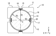
以下、本発明に係る光ファイバコイル用ボビンの好ましい実施形態の一例として、ボビン10を図面を参照して説明する。なお、ボビン10の構成を説明するにあたり、図1に示すように、互いに直交するX軸,Y軸,Z軸からなるXYZ座標系を想定する。
Hereinafter, a
ボビン10は、同図に示すように、全体として立方体(正六面体)の中実ブロック(本実施形態では、アルミニウム製のブロック)から形成されている。すなわち、ボビン10の外表面11は、全体として正方形をした同一形状の6つの平面部12〜14から構成されている。具体的に説明すると、外表面11は、X軸に垂直な一対の第1平面部12と、Y軸に垂直な一対の第2平面部13と、Z軸に垂直な一対の第3平面部14と、から構成されている。そして、3組の一対の平面部12〜14は、互いに直交している。
As shown in the figure, the
このように構成されたボビン10の外表面11には、光ファイバを巻回するための3つの巻線溝15,16,17(第1巻線溝15、第2巻線溝16、第3巻線溝17)が形成されている。3つの巻線溝15,16,17は、互いに直交し、かつ、3組の一対の平面部12〜14のうち2組の一対の平面部を周回するように形成されている。このため、6つの平面部12〜14の各々は、実際には3つの巻線溝15,16,17のうち2つの巻線溝によって4分割されている。
On the
次に、3つの巻線溝15,16,17について、図2ないし図4を参照して詳しく説明する。図2ないし図4は、それぞれY−Z面(X軸に直交する面),X−Z面(Y軸に直交する面),およびX−Y面(Z軸に直交する面)に平行で、ボビン10の中心点Cを通る断面図である。なお、図2ないし図4には、巻線溝15,16,17の底面に沿って光ファイバを巻回してなる3つの光ファイバコイル18,19,20(第1光ファイバコイル18,第2光ファイバコイル19,第3光ファイバコイル20)を模式的に示してある。
Next, the three
まず、第1巻線溝15は、図2に示すように、第1平面部12(Y−Z面)に対して平行に周回しており、その周回形状がボビン10の中心点Cを中心とする円形状に形成されている。なお、巻線溝15の周回形状とは、基本的には巻線溝15の底面(の中心)が囲う形状であるが、巻線溝17により底面が分断されている部分については外挿した形状(巻線溝17が存在しないと仮定した形状)である。すなわち、巻線溝15の周回形状とは、光ファイバコイル18の周回形状である。
First, as shown in FIG. 2, the
次に、第2巻線溝16は、図3に示すように、第2平面部13(X−Z面)に対して平行に周回しており、その周回形状がボビン10の中心点Cを中心とする円形状に形成されている。そして、第3巻線溝17は、図4に示すように、第3平面部14(X−Y面)に対して平行に周回しており、その周回形状がボビン10の中心点Cを中心とする円形状に形成されている。
Next, as shown in FIG. 3, the second winding
すなわち、3つの巻線溝15,16,17は、ボビン10の中心点Cを回転中心として同心状に形成されている。また、3つの巻線溝15,16,17は、その幅方向の断面形状が、外表面11を開放する矩形形状に形成されている。
That is, the three winding
また、3つの巻線溝15,16,17は、その周回形状の半径(中心点Cと巻線溝の底面間の最短距離)をそれぞれR1,R2,R3とすると、R1>R2>R3の関係になるように形成されている。
Further, the three winding
そして、第1巻線溝15における半径R1と第2巻線溝16における半径R2との差(R1−R2)が、少なくとも第2巻線溝16に装着される第2光ファイバコイル19の断面厚よりも大きく設定されている。また、第2巻線溝16における半径R2と第3巻線溝17における半径R3との差(R2−R3)が、少なくとも第3巻線溝17に装着される第3光ファイバコイル20の断面厚よりも大きく設定されている。要するに、3つの巻線溝15,16,17は、光ファイバコイル18,19,20間の干渉(接触)がない状態を確保できるように、半径R1,R2,R3がそれぞれ設定されている。
The difference (R1−R2) between the radius R1 of the first winding
次に、以上のように構成されたボビン10の従来技術に対する優位性について説明する。
Next, the superiority of the
ボビン10は、1つの中実ブロックから形成されることから、従来技術のように3つのボビンを組み付ける作業が不要となり、製造工程を簡略化することができる。また、ボビン10が中実ブロックから形成されていることから、ボビン10全体の堅牢性を向上させることができる。このため、ボビン10に加わった外力の光ファイバコイルへの伝達が抑制される。この結果、ボビン10を使用した光ファイバジャイロの測定精度が外力の影響を受けることがなくなり安定することが期待できる。
Since the
また、ボビン10は、全体として立方体に形成され、外表面11が6つの平面部12〜14から構成されていることから、いずれかの平面部12〜14を載置面として、ボビン10を光ファイバジャイロに安定して搭載できる。これにより、ボビンを光ファイバジャイロに取り付ける作業が容易になる。
Moreover, since the
また、ボビン10は、互いに直交する3つの巻線溝15,16,17の各々が、外表面11を構成し互いに直交する3組の一対の平面部12〜14のいずれかに平行に形成されている。このため、3組の一対の平面部12〜14(または、3つの平面部12,13,14)を加工基準面として、3つの巻線溝15,16,17を、例えば切削加工により形成することができる。これにより、各巻線溝15,16,17を互いに精度よく直交配置させることができる。
Further, in the
以上、本発明の好ましい実施形態の一例について説明したが、実施の形態については上記に限定されるものではなく、本発明の主旨を逸脱しない範囲で種々の変更が可能である。 Although an example of a preferred embodiment of the present invention has been described above, the embodiment is not limited to the above, and various modifications can be made without departing from the gist of the present invention.
例えば、ボビン10の全体形状を立方体としたが、これに代えて、直方体(六面体)としてもよいし、円柱としてもよい。円柱の場合には、加工精度の観点で立方体および直方体ほどの効果は期待できないが、円柱の軸方向両端の一対の平面部(または1つの平面部)を加工基準面とすることにより、一定の効果が期待できる。要するに、少なくとも1つの平面部を有する中実ブロックによりボビンが形成されていれば一定の効果が期待できる。
For example, although the entire shape of the
また、上記実施形態では、ボビン10に形成される巻線溝の数を3つとしたが、これに代えて、2つとしてもよい。
Moreover, in the said embodiment, although the number of the winding grooves formed in the
また、上記実施形態では、各巻線溝15,16,17の周回形状を円形状としたが、これに代えて、例えば楕円または矩形形状としてもよい。周回形状を楕円または矩形形状とすることにより、巻線溝の加工および光ファイバの巻き付け作業が困難になる可能性があるが、各巻線溝の周回面積を同一にすることが可能となる。なお、周回面積とは、各巻線溝に装着された光ファイバコイルによって囲まれる領域の面積である。
Moreover, in the said embodiment, although the circular shape of each winding groove |
ところで、光ファイバを使用した半導体リングレーザジャイロ(光ファイバジャイロの一形態)では、特願2008−210260(本出願時点では未公開)に開示されているように、光ファイバコイルによって囲まれる領域の面積によって角速度の測定性能が異なることが本発明者等により明らかにされている。したがって、各巻線溝の周回面積を同一にした多軸用ボビンは、軸ごとの測定性能を一致させることができることから、半導体リングレーザジャイロの多軸用ボビンとして有効である。 By the way, in a semiconductor ring laser gyro using an optical fiber (one form of optical fiber gyro), as disclosed in Japanese Patent Application No. 2008-210260 (not disclosed at the time of the present application), a region surrounded by an optical fiber coil is used. It has been clarified by the present inventors that the measurement performance of the angular velocity differs depending on the area. Therefore, the multi-axis bobbin in which the winding areas of the winding grooves are the same can match the measurement performance for each axis, and is therefore effective as a multi-axis bobbin for a semiconductor ring laser gyro.
なお、半導体リングレーザジャイロとは、半導体レーザの両端面から出射した2つの光の波長がサニャック効果によって互いに異なることにより発生するビート信号から角速度を検出する方式の光ジャイロである。このため、半導体リングレーザジャイロは、図5に示すように、両端面から光を出射させる半導体レーザ21と、半導体レーザ21とともにレーザ共振回路を構成する光ファイバからなる光ファイバリング22と、光ファイバリング22内に配置される光ファイバコイル23と、光ファイバリング22内を互いに逆方向に周回する光(CW光およびCCW光)の一部を分岐させる光分岐器24と、光分岐器24から分岐したCW光およびCCW光を重ね合わせることにより発生するビート信号の周波数から角速度を検出するための光検出器25と、を備えている。
The semiconductor ring laser gyro is an optical gyro that detects an angular velocity from a beat signal generated when the wavelengths of two lights emitted from both end faces of the semiconductor laser are different from each other due to the Sagnac effect. For this reason, as shown in FIG. 5, the semiconductor ring laser gyro includes a
また、上記実施形態では、3つの巻線溝15,16,17が同心状に形成されているが、必ずしも同心状に形成する必要はない。例えば、図6(a)(b)に示すボビン10Aのように、3つの巻線溝15A,16A,17Aの回転中心を互いにずらすことによって、円形状の周回形状であっても、3つの光ファイバコイル間に干渉を生じさせることのない条件下で、周回面積を互いに一致(半径Rを一致)させることができる。(なお、各巻線溝15A,16A,17Aの回転中心をずらしても、角速度の測定値は変化しない。)また、3つの巻線溝15A,16A,17Aの周回形状を円形状とすることにより、巻線溝の加工工程および光ファイバの巻き付け工程の作業性が向上する。なお、同図に示すように、ボビン10Aの全体形状を直方体としたが、直方体に代えて、例えば立方体とすることもできる。
Moreover, in the said embodiment, although the three winding
さらに、本発明に係るボビンは、干渉型光ファイバジャイロおよび半導体リングレーザジャイロに限定されることなく、光ファイバを使用するあらゆるタイプの光ジャイロに適用できる。 Furthermore, the bobbin according to the present invention is not limited to the interference type optical fiber gyroscope and the semiconductor ring laser gyroscope, but can be applied to any type of optical gyroscope using an optical fiber.
10,10A ボビン(光ファイバコイル用ボビン)
11 外表面
12 第1平面部
13 第2平面部
14 第3平面部
15,15A 第1巻線溝
16,16A 第2巻線溝
17,17A 第3巻線溝
18 第1光ファイバコイル
19 第2光ファイバコイル
20 第3光ファイバコイル
21 半導体レーザ
22 光ファイバリング
23 光ファイバコイル
24 光分岐器
25 光検出器
10, 10A bobbin (bobbin for optical fiber coil)
11
Claims (4)
互いに直交する3組の一対の平面部と、
光ファイバを巻回するための互いに直交し前記3組の一対の平面部のうち2組の一対の平面部をそれぞれ周回し、かつ、他の1組の一対の平面部に対して平行に周回する3つの巻線溝と、を外表面に有する中実ブロックからなり、
前記3つの巻線溝のうち少なくとも一つの巻線溝の底面が、他の巻線溝により分断されていることを特徴とする光ファイバコイル用ボビン。 An optical fiber coil bobbin used in an optical gyro that uses an optical fiber to detect the angular velocity of a moving object based on the Sagnac effect,
Three pairs of plane portions orthogonal to each other ;
Each of the three sets of the pair of plane portions that wrap around the optical fiber is wound around two pairs of plane portions, and in parallel with the other pair of plane portions. A solid block having three winding grooves on the outer surface,
The bobbin for an optical fiber coil , wherein a bottom surface of at least one of the three winding grooves is divided by another winding groove .
前記第2の巻線溝と前記第3の巻線溝とは、前記第1の巻線溝の回転中心からの距離が互いに異なる請求項3に記載の光ファイバコイル用ボビン。4. The bobbin for an optical fiber coil according to claim 3, wherein the second winding groove and the third winding groove have different distances from the rotation center of the first winding groove.
Priority Applications (1)
| Application Number | Priority Date | Filing Date | Title |
|---|---|---|---|
| JP2009096697A JP5275885B2 (en) | 2009-04-13 | 2009-04-13 | Bobbin for optical fiber coil |
Applications Claiming Priority (1)
| Application Number | Priority Date | Filing Date | Title |
|---|---|---|---|
| JP2009096697A JP5275885B2 (en) | 2009-04-13 | 2009-04-13 | Bobbin for optical fiber coil |
Publications (3)
| Publication Number | Publication Date |
|---|---|
| JP2010249557A JP2010249557A (en) | 2010-11-04 |
| JP2010249557A5 JP2010249557A5 (en) | 2012-03-22 |
| JP5275885B2 true JP5275885B2 (en) | 2013-08-28 |
Family
ID=43312071
Family Applications (1)
| Application Number | Title | Priority Date | Filing Date |
|---|---|---|---|
| JP2009096697A Active JP5275885B2 (en) | 2009-04-13 | 2009-04-13 | Bobbin for optical fiber coil |
Country Status (1)
| Country | Link |
|---|---|
| JP (1) | JP5275885B2 (en) |
Families Citing this family (2)
| Publication number | Priority date | Publication date | Assignee | Title |
|---|---|---|---|---|
| CN102645215B (en) * | 2012-05-16 | 2015-10-28 | 江苏立万信息科技有限公司 | The method for making of the optical fiber sensing ring of a kind of optical fibre gyro |
| US11047687B2 (en) | 2017-01-13 | 2021-06-29 | The Charles Stark Draper Laboratory, Inc. | Fiber management assembly for multi-axis fiber optic gyroscope |
Family Cites Families (6)
| Publication number | Priority date | Publication date | Assignee | Title |
|---|---|---|---|---|
| GB8432402D0 (en) * | 1984-12-21 | 1985-02-06 | Birch R D | Optical fibres |
| JPH06100470B2 (en) * | 1985-04-04 | 1994-12-12 | 住友電気工業株式会社 | Optical fiber sensor |
| JPS61266911A (en) * | 1985-05-22 | 1986-11-26 | Nippon Kogaku Kk <Nikon> | Surveying instrument using optical fiber gyro |
| JPH0317510A (en) * | 1989-06-15 | 1991-01-25 | Tamagawa Seiki Co Ltd | Optical fiber coil for three axis detection |
| JP4186147B2 (en) * | 1999-11-19 | 2008-11-26 | 株式会社エフ・イー・シー | 3D antenna |
| JP5013592B2 (en) * | 2006-12-24 | 2012-08-29 | オーエム機器株式会社 | Floor panel support structure |
-
2009
- 2009-04-13 JP JP2009096697A patent/JP5275885B2/en active Active
Also Published As
| Publication number | Publication date |
|---|---|
| JP2010249557A (en) | 2010-11-04 |
Similar Documents
| Publication | Publication Date | Title |
|---|---|---|
| US7684659B1 (en) | Bifilar optical fiber stowage for fiber-optic gyroscope | |
| US4259016A (en) | Interferometer with a single-mode waveguide coil | |
| EP0616195B1 (en) | Fiber optic gyroscope | |
| JP5004617B2 (en) | Aviation gradient gyroscope | |
| JP5275885B2 (en) | Bobbin for optical fiber coil | |
| JP2009199065A (en) | System and method for fiber based resonator coupling | |
| EP2069715A2 (en) | Photonic crystal based rotation sensor | |
| US11047687B2 (en) | Fiber management assembly for multi-axis fiber optic gyroscope | |
| EP3470785B1 (en) | Flange-bonded loopback for fiber-optic gyroscope (fog) | |
| US5357339A (en) | Multi-axis fiber-optic gyroscope assembly in which each gyroscope comprises 1/3 of a specific shape | |
| US20100238451A1 (en) | Depolarizer for a fiber optic gyroscope (fog) using high birefringence photonic crystal fiber | |
| JP7216951B2 (en) | Interferometric fiber optic gyro and sensing coil mechanism | |
| CN110285798B (en) | Miniaturized foldable nuclear magnetic resonance gyro instrument head | |
| JP2010230476A (en) | Ring laser gyro | |
| CN109579814B (en) | Optical fiber gyroscope | |
| JPH04148823A (en) | Optical fiber gyroscope | |
| US11774245B1 (en) | Vehicle hull with interferometric fiber-optic gyroscope | |
| CN216925602U (en) | Inertial measurement unit, navigation system and mobile device | |
| JPH0339689Y2 (en) | ||
| RU2488773C2 (en) | Laser gyroscope | |
| US20230008033A1 (en) | Folding sagnac inertia measurement unit | |
| CN107621260A (en) | A kind of optical fiber loop framework | |
| CN107607106A (en) | A kind of tunable optical fiber gyroscope | |
| JP2009150793A (en) | Interference fringe generation device, ring laser gyro, and forming method of ring laser gyro | |
| JP2009041940A (en) | Laser gyro |
Legal Events
| Date | Code | Title | Description |
|---|---|---|---|
| A521 | Written amendment |
Free format text: JAPANESE INTERMEDIATE CODE: A523 Effective date: 20120207 |
|
| A621 | Written request for application examination |
Free format text: JAPANESE INTERMEDIATE CODE: A621 Effective date: 20120207 |
|
| A977 | Report on retrieval |
Free format text: JAPANESE INTERMEDIATE CODE: A971007 Effective date: 20130104 |
|
| A131 | Notification of reasons for refusal |
Free format text: JAPANESE INTERMEDIATE CODE: A131 Effective date: 20130115 |
|
| A521 | Written amendment |
Free format text: JAPANESE INTERMEDIATE CODE: A523 Effective date: 20130313 |
|
| TRDD | Decision of grant or rejection written | ||
| A01 | Written decision to grant a patent or to grant a registration (utility model) |
Free format text: JAPANESE INTERMEDIATE CODE: A01 Effective date: 20130423 |
|
| A61 | First payment of annual fees (during grant procedure) |
Free format text: JAPANESE INTERMEDIATE CODE: A61 Effective date: 20130516 |
|
| R150 | Certificate of patent or registration of utility model |
Free format text: JAPANESE INTERMEDIATE CODE: R150 Ref document number: 5275885 Country of ref document: JP Free format text: JAPANESE INTERMEDIATE CODE: R150 |
|
| R250 | Receipt of annual fees |
Free format text: JAPANESE INTERMEDIATE CODE: R250 |
|
| R250 | Receipt of annual fees |
Free format text: JAPANESE INTERMEDIATE CODE: R250 |
|
| R250 | Receipt of annual fees |
Free format text: JAPANESE INTERMEDIATE CODE: R250 |
|
| R250 | Receipt of annual fees |
Free format text: JAPANESE INTERMEDIATE CODE: R250 |
|
| S533 | Written request for registration of change of name |
Free format text: JAPANESE INTERMEDIATE CODE: R313533 |
|
| R350 | Written notification of registration of transfer |
Free format text: JAPANESE INTERMEDIATE CODE: R350 |
|
| R250 | Receipt of annual fees |
Free format text: JAPANESE INTERMEDIATE CODE: R250 |