JP5275459B2 - Adapter for fixing the filter element - Google Patents
Adapter for fixing the filter element Download PDFInfo
- Publication number
- JP5275459B2 JP5275459B2 JP2011515142A JP2011515142A JP5275459B2 JP 5275459 B2 JP5275459 B2 JP 5275459B2 JP 2011515142 A JP2011515142 A JP 2011515142A JP 2011515142 A JP2011515142 A JP 2011515142A JP 5275459 B2 JP5275459 B2 JP 5275459B2
- Authority
- JP
- Japan
- Prior art keywords
- adapter
- filter
- seal
- seals
- groove
- Prior art date
- Legal status (The legal status is an assumption and is not a legal conclusion. Google has not performed a legal analysis and makes no representation as to the accuracy of the status listed.)
- Expired - Fee Related
Links
- 230000002093 peripheral effect Effects 0.000 claims description 21
- 239000000706 filtrate Substances 0.000 claims description 17
- 230000003014 reinforcing effect Effects 0.000 claims description 7
- 238000001746 injection moulding Methods 0.000 claims description 6
- 239000000243 solution Substances 0.000 claims description 4
- 238000005192 partition Methods 0.000 claims description 2
- 229920001296 polysiloxane Polymers 0.000 claims description 2
- 229920002725 thermoplastic elastomer Polymers 0.000 claims description 2
- 229920002803 thermoplastic polyurethane Polymers 0.000 claims description 2
- 238000000465 moulding Methods 0.000 claims 1
- 238000002347 injection Methods 0.000 description 14
- 239000007924 injection Substances 0.000 description 14
- 238000007789 sealing Methods 0.000 description 12
- 239000007788 liquid Substances 0.000 description 9
- 239000012530 fluid Substances 0.000 description 6
- 239000000463 material Substances 0.000 description 5
- 238000004519 manufacturing process Methods 0.000 description 3
- 239000004033 plastic Substances 0.000 description 3
- 229920003023 plastic Polymers 0.000 description 3
- 238000000034 method Methods 0.000 description 2
- 239000003566 sealing material Substances 0.000 description 2
- 230000006978 adaptation Effects 0.000 description 1
- 230000004888 barrier function Effects 0.000 description 1
- 230000007547 defect Effects 0.000 description 1
- 238000001914 filtration Methods 0.000 description 1
- 238000003780 insertion Methods 0.000 description 1
- 230000037431 insertion Effects 0.000 description 1
- 238000011085 pressure filtration Methods 0.000 description 1
- 238000000638 solvent extraction Methods 0.000 description 1
- 238000005507 spraying Methods 0.000 description 1
- 230000007704 transition Effects 0.000 description 1
Images


Classifications
-
- B—PERFORMING OPERATIONS; TRANSPORTING
- B01—PHYSICAL OR CHEMICAL PROCESSES OR APPARATUS IN GENERAL
- B01D—SEPARATION
- B01D29/00—Filters with filtering elements stationary during filtration, e.g. pressure or suction filters, not covered by groups B01D24/00 - B01D27/00; Filtering elements therefor
- B01D29/11—Filters with filtering elements stationary during filtration, e.g. pressure or suction filters, not covered by groups B01D24/00 - B01D27/00; Filtering elements therefor with bag, cage, hose, tube, sleeve or like filtering elements
- B01D29/111—Making filtering elements
-
- B—PERFORMING OPERATIONS; TRANSPORTING
- B01—PHYSICAL OR CHEMICAL PROCESSES OR APPARATUS IN GENERAL
- B01D—SEPARATION
- B01D29/00—Filters with filtering elements stationary during filtration, e.g. pressure or suction filters, not covered by groups B01D24/00 - B01D27/00; Filtering elements therefor
- B01D29/11—Filters with filtering elements stationary during filtration, e.g. pressure or suction filters, not covered by groups B01D24/00 - B01D27/00; Filtering elements therefor with bag, cage, hose, tube, sleeve or like filtering elements
- B01D29/13—Supported filter elements
- B01D29/15—Supported filter elements arranged for inward flow filtration
- B01D29/21—Supported filter elements arranged for inward flow filtration with corrugated, folded or wound sheets
-
- B—PERFORMING OPERATIONS; TRANSPORTING
- B01—PHYSICAL OR CHEMICAL PROCESSES OR APPARATUS IN GENERAL
- B01D—SEPARATION
- B01D2201/00—Details relating to filtering apparatus
- B01D2201/04—Supports for the filtering elements
- B01D2201/043—Filter tubes connected to plates
- B01D2201/0438—Filter tubes connected to plates mounted substantially vertically on plates at the lower side of the filter elements
-
- B—PERFORMING OPERATIONS; TRANSPORTING
- B01—PHYSICAL OR CHEMICAL PROCESSES OR APPARATUS IN GENERAL
- B01D—SEPARATION
- B01D2201/00—Details relating to filtering apparatus
- B01D2201/29—Filter cartridge constructions
- B01D2201/291—End caps
-
- B—PERFORMING OPERATIONS; TRANSPORTING
- B01—PHYSICAL OR CHEMICAL PROCESSES OR APPARATUS IN GENERAL
- B01D—SEPARATION
- B01D2201/00—Details relating to filtering apparatus
- B01D2201/34—Seals or gaskets for filtering elements
-
- Y—GENERAL TAGGING OF NEW TECHNOLOGICAL DEVELOPMENTS; GENERAL TAGGING OF CROSS-SECTIONAL TECHNOLOGIES SPANNING OVER SEVERAL SECTIONS OF THE IPC; TECHNICAL SUBJECTS COVERED BY FORMER USPC CROSS-REFERENCE ART COLLECTIONS [XRACs] AND DIGESTS
- Y10—TECHNICAL SUBJECTS COVERED BY FORMER USPC
- Y10S—TECHNICAL SUBJECTS COVERED BY FORMER USPC CROSS-REFERENCE ART COLLECTIONS [XRACs] AND DIGESTS
- Y10S277/00—Seal for a joint or juncture
- Y10S277/91—O-ring seal
Description
本発明は、フィルターハウジング下部の底部分の円筒状受入開口部においてフィルターエレメントを固定するためのアダプターであって、かかるアダプターは、非ろ液チャンバーの流体密の仕切りを可能とするための、アダプター周囲の周辺溝に配置される少なくとも1つのシールを含み、フィルターの外側ジャケットを囲み、ろ過される溶液をフィルターへと供給することができ、ろ液チャンバーへのろ液をフィルターから導入することができる、前記アダプターに関する。 The present invention is an adapter for fixing a filter element in a cylindrical receiving opening at the bottom part of the lower part of the filter housing, which adapter is used to enable fluid-tight partitioning of a non-filtrate chamber Including at least one seal disposed in a peripheral peripheral groove, enclosing the outer jacket of the filter, capable of supplying the solution to be filtered to the filter, and introducing filtrate into the filtrate chamber from the filter; It can be related to the adapter.
DE 33 35 938 C1は、流体の圧力ろ過のための複数部フィルターハウジングであって、ハウジング上部およびハウジング基部を備えるハウジング底部を有し、前記ハウジング基部は、フィルターキャンドルまたはフィルターエレメントを、アダプターを介して受入れるための円筒状開口部を有し、フィルターキャンドルの外側ジャケットを囲む非ろ液チャンバーは、フィルターキャンドルが連結される中央排出口を介して、ろ液チャンバーから仕切られる、前記フィルターハウジングを開示する。フィルターキャンドルは、その縦方向の下端部に、管状アダプターが連結される中央排出口を備える流体密の環状端部キャップを有し、フィルターキャンドルは、前記管状アダプターを介して、ハウジング底部の円筒状開口部へ挿入される。フィルターキャンドルは、その流体透過性の外側ジャケットと共に、非ろ液チャンバーに位置し、ハウジング底部から離れた方向にある上縁部を有する環状端部キャップが、外側ジャケットへ流体密の移行領域を形成する。ハウジング底部の円筒状開口部におけるアダプターをシールするため、既知のアダプターは2つの並行する周辺溝を有し、それぞれにはO−リングがシールとして配置されている。 DE 33 35 938 C1 is a multi-part filter housing for pressure filtration of fluids, having a housing bottom with a housing top and a housing base, said housing base having a filter candle or filter element via an adapter A non-filtrate chamber having a cylindrical opening for receiving and enclosing the outer jacket of the filter candle is partitioned from the filtrate chamber via a central outlet to which the filter candle is connected. To do. The filter candle has a fluid-tight annular end cap with a central outlet to which a tubular adapter is connected at the lower end in the vertical direction, and the filter candle is cylindrical at the bottom of the housing via the tubular adapter. It is inserted into the opening. The filter candle, together with its fluid permeable outer jacket, is located in a non-filtrate chamber and an annular end cap with an upper edge in a direction away from the bottom of the housing forms a fluid tight transition region to the outer jacket To do. In order to seal the adapter in the cylindrical opening at the bottom of the housing, the known adapter has two parallel peripheral grooves, each with an O-ring arranged as a seal.
既知のアダプターにおいて見つかった原理上の不利益は、O−リングまたはひも状シールが、別々に取り付けられる必要があることである。これは、少なくとも利用者によってはめられる不正確なシール、またはシールの1つが省略され得ることを意味する。 A principle disadvantage found in known adapters is that the O-rings or string seals need to be attached separately. This means that at least one of the inaccurate seals or seals fitted by the user can be omitted.
DE 43 25 997 A1は、液体排出ノズル上のフィルターエレメントを固定するためのアダプターを開示する。液体排出ノズルに向けられた内部壁の上に、アダプターは、非ろ液チャンバーの流体密の仕切りのための、そこへ配置されるシールを備えた周辺溝を有し、それはフィルターの外側ジャケットを囲み、そこからろ過される溶液がろ過後にフィルターへと供給される。シールは、溝の基部表面の境界を定める少なくとも片側の壁から一定の距離がある。 DE 43 25 997 A1 discloses an adapter for fixing a filter element on a liquid discharge nozzle. On the inner wall directed to the liquid discharge nozzle, the adapter has a peripheral groove with a seal placed therein for the fluid tight partition of the non-filtrate chamber, which is attached to the outer jacket of the filter. The solution enclosed and filtered from there is fed to the filter after filtration. The seal has a distance from at least one wall that delimits the base surface of the groove.
DE 43 25 997 A1の教示によると、信頼できるシールは、ろ過されて、液体フィルターを通して流れる液体によって提供されるが、それはこの液体が、フィルター挿入部を通して流れるときに生じる圧力差の結果として、低い液体圧とともに、液体フィルター部分の方向に溝の内側の封止リングを押し出すためである。この方法において、液体フィルターまたはフィルターエレメントの作業の間に、シールは、封止リングまたはシールの、低いまたは存在さえしない弾性プレテンションにもかかわらず、ここで確かめるように封止リングまたはシールが、液体排出ノズルおよびそこに隣接した溝の境界表面上に圧迫される。 According to the teachings of DE 43 25 997 A1, a reliable seal is provided by a liquid that is filtered and flows through a liquid filter, which is low as a result of the pressure difference that occurs when this liquid flows through the filter insert This is because the sealing ring inside the groove is pushed out in the direction of the liquid filter portion together with the liquid pressure. In this way, during the operation of the liquid filter or filter element, the sealing ring or seal, as verified here, despite the low or even non-existent elastic pretension of the sealing ring or seal, It is squeezed onto the boundary surface of the liquid discharge nozzle and the adjacent groove.
DE 43 25 997 A1の装置において、封止リングまたはシールが、端部ディスク部分の隣接位置に上向きに圧迫されることを確かめるため、ろ過される流体は、環状ギャップを通して溝の中へ流れる必要が常にあり、そのとき初めて封止が達成される。 In the device of DE 43 25 997 A1, the fluid to be filtered must flow through the annular gap into the groove to ensure that the sealing ring or seal is pressed upwards adjacent to the end disk part. There is always, and only then is sealing achieved.
DE 20 2006 014 784 U1は、フィルター本体の端部を覆う端部ディスクが、有孔ディスクおよび後者に配置されるカラー(collar)によって1つに形成される、環状フィルター挿入部を開示する。カラーは、軸方向の支持表面および放射状の支持表面を有する。熱エネルギー除去のためのポケットを有する放射状封止リングは、二成分プロセス(two-component process)において、または射出成形によって、これら支持表面に適用可能である。この放射状封止リングは、軸方向の支持表面によって底部、および放射状の支持表面によって側面だけに制限され、ろ液の流出方向において、それは開放している。放射状封止リングは、端部ディスクのカラー、すなわち、アダプター内部の周囲で一体化して形成される。 DE 20 2006 014 784 U1 discloses an annular filter insert in which an end disk covering the end of the filter body is formed in one by a perforated disk and a collar arranged in the latter. The collar has an axial support surface and a radial support surface. Radial sealing rings with pockets for heat energy removal can be applied to these support surfaces in a two-component process or by injection molding. This radial sealing ring is limited to the bottom by the axial support surface and to the sides only by the radial support surface, which is open in the filtrate outflow direction. The radial sealing ring is integrally formed around the collar of the end disk, i.e. inside the adapter.
中空ポケットのため、放射状封止リングは、製造するのに非常に複雑であり、特に、材料ウェブ(web)または中空ポケット底部の破損および漏洩が結果としてそこに生じた場合、その製造の間の放射状封止リングの欠陥は、光学的に検出することが困難でしかない。 Due to the hollow pockets, radial sealing rings are very complex to manufacture, especially if the material web (hollow) or hollow pocket bottom breaks and leaks as a result there during production. Defects in the radial sealing ring can only be difficult to detect optically.
さらに、EP 1 156 538 B1は、気密の方法で蓄電池の電池通気口を閉じるための栓の配置を開示する。密閉栓は、そこに一体化形成された環状シールとともに、その周囲に溝を有する。環状シールは、二成分射出成形プロセスで形成された。溝は、環状シールによって完全に満たされている。
Furthermore,
さらに、DE 10 2005 033 665 A1は、内部の周辺溝において、射出成形されたシールを有する栓のための受入部を開示する。ここにおいても、溝は封止材によって完全に満たされている。 Furthermore, DE 10 2005 033 665 A1 discloses a receiving part for a plug having an injection-molded seal in an internal peripheral groove. Again, the groove is completely filled with the sealing material.
シールの材料で溝を完全に満たすことの不利益は、容積変形に必要な隙間を、溝の外側に作る必要があることである。 The disadvantage of completely filling the groove with the material of the seal is that the gap necessary for volume deformation needs to be created outside the groove.
特別な不利益は、アダプターと受入開口部との間の許容範囲を、容積変形のための隙間を作るために、変化させる必要があることである。 A special disadvantage is that the tolerance between the adapter and the receiving opening needs to be changed in order to create a gap for volume deformation.
さらに、DE 44 22 842 C1は、流体密となるように、弾性のある封止材を使用して一緒にはめられた、少なくとも2つの個々の部分を有するハウジングがある装置を開示する。個々の部分の少なくとも1つは、2つの材料成分を含み、1つは封止材であってシールを提供し、ここで、これら2つの材料成分の多くても1つは前成形として、または噴霧によって、封止材とともに射出成形金型の挿入部として結合させ、または、両成分は二成分射出成形金型、すなわち、2つの穴がある射出成形金型において、一緒に噴霧される。 Furthermore, DE 44 22 842 C1 discloses a device in which there is a housing with at least two individual parts that are fitted together using a resilient seal so as to be fluid tight. At least one of the individual parts includes two material components, one is a seal and provides a seal, where at most one of these two material components is as a preform or By spraying, it is combined with the sealing material as an insert in an injection mold, or both components are sprayed together in a two-component injection mold, ie an injection mold with two holes.
それゆえに本発明の目的は、シールを別々に適合させることを回避可能とするように、底部分の円筒状受入開口部におけるフィルターエレメントの固定のための既知のアダプターを改善することである。さらに、新規アダプターおよび既存の受入開口部における従来の既知アダプターも使用可能とするため、アダプターと受入開口部との間の許容範囲の変化は、可能な限り避けられる。 The object of the present invention is therefore to improve the known adapter for fixing the filter element in the cylindrical receiving opening in the bottom part so that it is possible to avoid adapting the seals separately. In addition, new adapters and existing known adapters in existing receiving openings can be used so that tolerance changes between the adapter and the receiving opening are avoided as much as possible.
目的は、請求項1の前文(preamble)と関連して、シールが射出成形によって、周辺溝の基部表面に連結される事実によって達成され、シールは、溝の基部表面の境界を定める少なくとも1つの側壁から一定の距離がある。
The object is achieved in connection with the preamble of
シールが、周辺溝の基部表面に射出成形されているという事実のおかげで、別々に適合させる手間が省ける。同時に、製造業者によって販売され、目的の材料で作られた正確な封止リングが、アダプターの溝に配置されることを確実にする。シールと溝の基部表面の境界を定める少なくとも1つの側壁との間の距離は、底部分の円筒状受入開口部への挿入時に、シールの変形容積を吸収するための空間をもたらす。したがって、円筒状受入開口部およびアダプター外形との間の許容範囲の変化を避けることが可能となる。これは、本発明によるアダプターとともに新規フィルターエレメント、および既知アダプターとともに従来のフィルターエレメントを、既知フィルターハウジングまたはそれらの底部プレートの既存の円筒状開口部に挿入可能であることを意味する。 Thanks to the fact that the seal is injection molded on the base surface of the peripheral groove, it is possible to dispense with the need for separate adaptation. At the same time, ensure that the exact sealing ring sold by the manufacturer and made of the material of interest is placed in the groove of the adapter. The distance between the seal and at least one sidewall delimiting the base surface of the groove provides a space for absorbing the deformed volume of the seal upon insertion into the cylindrical receiving opening in the bottom portion. Therefore, it is possible to avoid a change in the allowable range between the cylindrical receiving opening and the adapter outer shape. This means that new filter elements with adapters according to the invention and conventional filter elements with known adapters can be inserted into existing cylindrical openings in known filter housings or their bottom plates.
本発明の好ましい態様によると、シールは、溝の中央に配置され、溝の基部表面の境界を定める両側壁から一定の距離がある。これは、特に、単一の溝にシールを射出成形する場合に、比較的簡単に行うことができる。好ましい態様によると、第二のシールは、第二の周辺溝における基部表面上に射出成形される。第一および第二のシールは、2つの相互に並行する溝の基部表面上に射出成形され、シールは、溝の2つの相互に向き合う内側側壁を直接支える。隔たりは、射出成形の間に、適した挿入具によって充填される。 According to a preferred embodiment of the present invention, the seal is located in the middle of the groove and is at a certain distance from the side walls that delimit the base surface of the groove. This can be done relatively easily, particularly when the seal is injection molded in a single groove. According to a preferred embodiment, the second seal is injection molded on the base surface in the second peripheral groove. The first and second seals are injection molded on the base surfaces of the two mutually parallel grooves, and the seals directly support the two mutually facing inner sidewalls of the grooves. The gap is filled with a suitable insert during injection molding.
2つのシールが、少なくとも1つのウェブ、好ましくは3または4の軸方向に延びるウェブによって互いに連結された場合、特に有利であることが証明された。このようにして、2つの相互接続されたシールは、非ろ液チャンバーと、アダプターとともにフィルターエレメントを含むフィルターハウジングのろ液チャンバーとの間に、特に密なバリアを形成する。 It has proved to be particularly advantageous if the two seals are connected to each other by at least one web, preferably 3 or 4 axially extending webs. In this way, the two interconnected seals form a particularly tight barrier between the non-filtrate chamber and the filtrate chamber of the filter housing containing the filter element with the adapter.
本発明の好ましい態様によると、フィルターエレメントの端部キャップ領域中の周辺溝において、第三のシールが溝の基部表面上に射出成形される。アダプターに隣接するフィルターエレメントの端部キャップ領域中の第三のシールの配置のおかげで、端部キャップを含むフィルターエレメントは、非ろ液チャンバーに実質的にデッドスペースがないように、かつ、非ろ液チャンバーに置かれるろ過される溶液のすべてが、フィルターを通してろ過され、ろ液チャンバーに運ばれるように、底部分の対応する受入開口部中に挿入することができる。 According to a preferred embodiment of the present invention, a third seal is injection molded on the base surface of the groove in the peripheral groove in the end cap region of the filter element. Thanks to the arrangement of the third seal in the end cap region of the filter element adjacent to the adapter, the filter element containing the end cap is substantially free of dead space in the non-filtrate chamber and non- All of the filtered solution that is placed in the filtrate chamber can be filtered through the filter and inserted into the corresponding receiving opening in the bottom portion so that it can be carried to the filtrate chamber.
本発明の好ましい態様によると、シールは、熱可塑性エラストマー、熱可塑性ウレタン、またはシリコーンで作られる。 According to a preferred embodiment of the invention, the seal is made of a thermoplastic elastomer, thermoplastic urethane, or silicone.
本発明の好ましい態様によると、アダプターは封入された補強リングを備える本体を有する。アダプターは、好ましくはフィルターエレメントの端部キャップに接合される。しかしながら、端部キャップ上に一体化して形成することもできる。 According to a preferred embodiment of the invention, the adapter has a body with an enclosed reinforcing ring. The adapter is preferably joined to the end cap of the filter element. However, it can also be formed integrally on the end cap.
本発明のさらなる特徴は、続く詳細な記載、および本発明の好ましい態様が例示によって図解される添付図面から明確になるだろう。 Further features of the present invention will become apparent from the following detailed description and the accompanying drawings, in which preferred embodiments of the invention are illustrated by way of example.
図において:
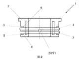
アダプター1は、基本的に、本体2、周辺溝3およびシール4を含む。
The
周辺の第一の溝3と並行して、周辺の第二の溝5が、アダプター1の本体2に配置される。周辺溝3、5はそれぞれ、基部表面6、第一の周辺溝における基部表面6上に射出成形されるシール4、および第二の周辺溝における基部表面6上に射出成形される第二のシール7を有する。シール4、7は、その内側表面8、9が、隣接する溝3、5の内側側壁10、11上に直接位置しており、または射出成形によって側壁10、11と連結している。シール4、7の内側表面8、9から離れた方向にある外側表面14、15は、内側側壁10、11から離れた方向にある外側側壁12、13からそれぞれ一定の距離16、17があり、その距離16、17は、アダプター1が底部分19の円筒状開口部18の中へ挿入された場合、シール4、7の変形容積を吸収するための空間を提供する。
A peripheral
シール4、7は、ウェブ20によって互いに連結される。ウェブ20の1つは、射出点21として使用することができる。しかしながら、射出点23とともに追加ウェブ22を提供することもできる。
The
図3によると、アダプター1は、フィルターエレメント25の下側の端部キャップ24の中へ挿入され、そこへ接合される。しかしながら、図4に示される例示の実施態様によると、アダプター1’は、フィルターエレメント25’の下側の端部キャップ24’上に一体化して形成することもできる。
According to FIG. 3, the
図4における例示の実施態様によると、下側の端部キャップ24’は、その周囲に第三の周辺溝26を有し、前記溝の基部表面27上には、その側面29、30が、第三の溝26の側壁32、33からそれぞれ一定の距離31となるように、第三のシール28が中央に射出成形される。
According to the exemplary embodiment in FIG. 4, the
アダプター1、1’を製造するための道具(図示されていない)は、例えば、固定された工具部分内の2つの空洞および可動式工具部分上の回転式工具プレートからなる。各射出作業の後、工具は開き、回転式工具プレートは、第一の空洞に作られたプラスチック部分を、第二の空洞正面の位置へ運ぶ。これは、次に続く方法の工程を含む。
a)補強リング34が、第一の空洞にはめられる、
b)工具が閉じる、
c)本体2が、第一の空洞中の補強リング34の周りに射出される、
d)工具が開く、
e)工具プレートが回転し、本体2が第二の空洞へ運ばれる、
f)補強リング34が、第一の空洞へはめられる、
g)工具が閉じる、
h)本体2が、第一の空洞中の補強リング34の周りに射出され、シール4、7が、第二の空洞中のアダプター1上に射出される、
i)工具が開く、
j)第二の空洞に作られたアダプター1が、取り除かれる、
k)工具プレートが回転する、
a)補強リング34が、再び第一の空洞にはめられる、
b)工具が閉じ、工程c)からk)が繰り返される。
当然、工具は、固定工具半分において3またはそれ以上の空洞および可動式工具半分の回転式工具プレートからなることもできる。
A tool (not shown) for manufacturing the
a) a reinforcing
b) The tool closes,
c) the
d) The tool opens,
e) The tool plate rotates and the
f) A reinforcing
g) The tool closes,
h) The
i) The tool opens,
j) The
k) The tool plate rotates,
a) The reinforcing
b) The tool is closed and steps c) to k) are repeated.
Of course, the tool can also consist of three or more cavities in the fixed tool half and a rotary tool plate in the movable tool half.
各射出作業の後、工具は開き、回転式工具プレートは、第一の空洞に作られたプラスチック部分を、第二の空洞正面の位置へ運び、第二の空洞に作られたプラスチック部分を、第三の空洞正面の位置へ運ぶ。 After each injection operation, the tool is opened and the rotary tool plate carries the plastic part made in the first cavity to the position in front of the second cavity, the plastic part made in the second cavity, Carry to the position in front of the third cavity.
当然、説明において検討され、および図によって示された態様は、本発明の例示的態様にすぎない。本願明細書の開示を考慮すると、可能な変化が広範囲であることが、当業者には明白である。 Of course, the embodiments discussed in the description and illustrated by the figures are merely exemplary embodiments of the invention. In view of the disclosure herein, it will be apparent to those skilled in the art that the range of possible variations is wide.
例えば、シール4、7、28は、基部表面6、27から離れる側に、凸状である。しかしながら、原則として、それらは他の形を有することもできる。
For example, the
Claims (6)
該アダプターは、非ろ液チャンバーの流体密の仕切りを可能とするための、アダプター周囲の周辺溝(3、5)に配置されるシール(4、7)を含み、非ろ液チャンバーはフィルターの外側ジャケットを囲み、ろ過される溶液をフィルターへと供給することができ、ろ液をフィルターからろ液チャンバーへ導入することができ、
該周辺溝(3、5)は、それぞれ、溝の底に相当する基部表面(6)と、該基部表面(6)を挟む、フィルター側の側壁(12、11)と、チャンバー側の側壁(10、13)を有しており、
2つのO−リングタイプのシール(4、7)は、それぞれ射出成形によって、相互に並行する2つの周辺溝(3、5)のそれぞれの基部表面(6)に配置され、
該シール(4、7)は、それぞれ、該周辺溝(3、5)の2つの相互に向き合う内側の側壁(10、11)に接しており、
該シール(4、7)は、それぞれ、該周辺溝(3、5)の他側の側壁(12、13)から一定の距離(16、17)離間しており、
該シール(4、7)は、介在する内側の側壁(10、11)を跨いで軸方向に延びる接合部(20)によって互いに連結されていることを特徴とする、前記アダプター。 An adapter (1, 1 ') for fixing the filter element (25, 25') in the cylindrical receiving opening (18) of the bottom part (19) of the lower part of the filter housing,
The adapter includes for enabling the partition of the fluid-tight non-filtrate chamber, disposed around the groove around the adapter (3,5) Resid Lumpur (4,7), the non-filtrate chamber Surrounds the outer jacket of the filter, can supply the solution to be filtered to the filter, can introduce the filtrate from the filter to the filtrate chamber,
The peripheral grooves (3, 5) include a base surface (6) corresponding to the bottom of the groove, filter side walls (12, 11) sandwiching the base surface (6), and chamber side walls ( 10, 13)
Two O-ring type seals (4, 7 ) are respectively placed on the respective base surfaces (6) of two peripheral grooves (3, 5 ) parallel to each other by injection molding,
The seals (4, 7 ) are in contact with two mutually facing inner side walls (10, 11) of the peripheral grooves (3, 5 ) , respectively .
The seals (4, 7) are respectively separated from the other side walls (12, 13) of the peripheral grooves (3, 5) by a certain distance (16, 17);
The seal (4,7) is characterized Tei Rukoto connected to each other by joints extending in the axial direction (20) across the side wall of the inner intervening (10, 11), said adapter.
Applications Claiming Priority (3)
| Application Number | Priority Date | Filing Date | Title |
|---|---|---|---|
| DE102008031170.7 | 2008-07-03 | ||
| DE102008031170A DE102008031170B4 (en) | 2008-07-03 | 2008-07-03 | Adapter for fixing a filter element |
| PCT/EP2009/003759 WO2010000356A2 (en) | 2008-07-03 | 2009-05-27 | Adapter for fastening a filter element |
Publications (3)
| Publication Number | Publication Date |
|---|---|
| JP2011526201A JP2011526201A (en) | 2011-10-06 |
| JP2011526201A5 JP2011526201A5 (en) | 2011-11-17 |
| JP5275459B2 true JP5275459B2 (en) | 2013-08-28 |
Family
ID=41060991
Family Applications (1)
| Application Number | Title | Priority Date | Filing Date |
|---|---|---|---|
| JP2011515142A Expired - Fee Related JP5275459B2 (en) | 2008-07-03 | 2009-05-27 | Adapter for fixing the filter element |
Country Status (6)
| Country | Link |
|---|---|
| US (1) | US8177972B2 (en) |
| EP (1) | EP2296776B1 (en) |
| JP (1) | JP5275459B2 (en) |
| CN (1) | CN102076395B (en) |
| DE (2) | DE102008031170B4 (en) |
| WO (1) | WO2010000356A2 (en) |
Families Citing this family (8)
| Publication number | Priority date | Publication date | Assignee | Title |
|---|---|---|---|---|
| DE102008049627A1 (en) * | 2008-09-30 | 2010-04-08 | Mann + Hummel Gmbh | Method for producing a filter end disk and a fluid filter, motor vehicle fluid filter |
| DE102009056511A1 (en) * | 2009-12-02 | 2011-06-09 | Mann+Hummel Gmbh | Filter element and method of making a filter element |
| BR102014020222A2 (en) * | 2014-08-14 | 2015-06-09 | Devocir Antônio Lira | Universal fuel filter connector for agricultural machinery |
| US11383188B2 (en) * | 2019-06-07 | 2022-07-12 | Pall Corporation | Filter capsule and method of use |
| KR102293863B1 (en) * | 2020-03-23 | 2021-08-26 | 엘지전자 주식회사 | water purifying apparatus refrigerator |
| KR20220141605A (en) | 2021-04-13 | 2022-10-20 | 엘지전자 주식회사 | Water purifying apparatus and refrigerator having this |
| CA3217376A1 (en) * | 2021-05-05 | 2022-11-10 | William N. Tally | Sealing assembly and method of use thereof |
| CN114131855B (en) * | 2021-11-26 | 2023-11-14 | 乐清昌德成电子有限公司 | Plug forming die |
Family Cites Families (15)
| Publication number | Priority date | Publication date | Assignee | Title |
|---|---|---|---|---|
| US3850813A (en) * | 1972-10-27 | 1974-11-26 | Pall Corp | End caps with peripheral grooves for tubular filter elements and process for making the same |
| US3865386A (en) * | 1973-04-20 | 1975-02-11 | Koehring Co | Oil sealing device |
| DE3335938C1 (en) | 1983-10-04 | 1985-04-04 | Sartorius GmbH, 3400 Göttingen | Multi-part filter housing for pressure filtration |
| US4839037A (en) * | 1987-03-09 | 1989-06-13 | Osmonics, Inc. | Tapered, spirally wound filter cartridge and method of making same |
| US5238717A (en) * | 1991-04-26 | 1993-08-24 | Pall Corporation | End caps for filter elements |
| EP0547291B1 (en) * | 1991-12-17 | 1999-09-15 | FILTERWERK MANN & HUMMEL GMBH | Fuel filter and/or lubricating oil filter for internal combustion engines |
| DE4325997C1 (en) * | 1993-08-03 | 1994-09-01 | Hengst Walter Gmbh & Co Kg | Liquid filter having a filter insert |
| DE4422842C1 (en) | 1994-06-30 | 1995-08-17 | Sidler Gmbh & Co | Sealed housing useful for shrouding for powered rotating components |
| EP0937674B1 (en) * | 1998-02-13 | 2002-03-27 | eloma GmbH Grossküchentechnik | Hose reeling device |
| FR2785826B1 (en) * | 1998-11-16 | 2001-01-12 | Fleetguard | LIQUID FILTER CARTRIDGE CIRCULATING IN A MOTOR OR HYDRAULIC EQUIPMENT AND CORRESPONDING FILTRATION CARTRIDGE-SEAL ASSEMBLY |
| US6953526B1 (en) * | 2000-03-22 | 2005-10-11 | Cuno Incorporated | Filter assembly |
| DE10023747A1 (en) | 2000-05-15 | 2001-11-22 | Hoppecke Zoellner Sohn Accu | Plug arrangement |
| GB2383002B (en) * | 2001-12-13 | 2004-10-27 | Pall Corp | Filter assemblies |
| DE102005033665A1 (en) | 2005-07-19 | 2007-02-08 | Elsässer, Helmut | Receiving part for a plug |
| DE202006014784U1 (en) * | 2006-09-26 | 2008-02-07 | Hengst Gmbh & Co.Kg | Ring filter insert for a filter |
-
2008
- 2008-07-03 DE DE102008031170A patent/DE102008031170B4/en not_active Expired - Fee Related
-
2009
- 2009-05-27 JP JP2011515142A patent/JP5275459B2/en not_active Expired - Fee Related
- 2009-05-27 US US12/999,361 patent/US8177972B2/en active Active
- 2009-05-27 EP EP09772056.9A patent/EP2296776B1/en active Active
- 2009-05-27 CN CN200980125431.8A patent/CN102076395B/en active Active
- 2009-05-27 WO PCT/EP2009/003759 patent/WO2010000356A2/en active Application Filing
- 2009-06-19 DE DE202009008466U patent/DE202009008466U1/en not_active Expired - Lifetime
Also Published As
| Publication number | Publication date |
|---|---|
| EP2296776A2 (en) | 2011-03-23 |
| CN102076395B (en) | 2014-06-18 |
| WO2010000356A3 (en) | 2010-02-25 |
| DE202009008466U1 (en) | 2009-09-10 |
| JP2011526201A (en) | 2011-10-06 |
| EP2296776B1 (en) | 2016-10-12 |
| CN102076395A (en) | 2011-05-25 |
| WO2010000356A2 (en) | 2010-01-07 |
| DE102008031170A1 (en) | 2010-01-14 |
| US8177972B2 (en) | 2012-05-15 |
| DE102008031170B4 (en) | 2010-06-17 |
| US20110100892A1 (en) | 2011-05-05 |
Similar Documents
| Publication | Publication Date | Title |
|---|---|---|
| JP5275459B2 (en) | Adapter for fixing the filter element | |
| JP5491489B2 (en) | Filter vial apparatus having a tubular piston, a holding cup, and a filter, a filter vial assembly, and a method for forming a filter vial piston | |
| CN105074409B (en) | For the method for manufacturing sensor housing and corresponding sensor housing | |
| KR100898619B1 (en) | Fluid pumping apparatus | |
| KR960704611A (en) | Fluid filter assembly for vehicles | |
| JP4991724B2 (en) | Reverse osmosis filtration system storage tank | |
| BRPI0803516B1 (en) | Fluid Filter Device with Outer Cap | |
| US20100200617A1 (en) | Cartridge piston with venting device | |
| EP2024050B1 (en) | Filter system | |
| JP2011526201A5 (en) | ||
| CN109689181A (en) | Filter element and filtration system | |
| CN110290909B (en) | Method for producing a container | |
| RU2543183C2 (en) | Collector for inkjet cartridge | |
| WO2007003245A1 (en) | Spray gun reservoir comprising a liquid tight vent | |
| ITRE20110048A1 (en) | DISPOSABLE CARTRIDGE FOR DRINK PREPARATION | |
| JP5635237B2 (en) | Container to be molded | |
| JP2013508626A5 (en) | ||
| CN107975620A (en) | Spool and the valve equipped with the spool | |
| CN202355944U (en) | Filter and ventilation filtering apparatus | |
| KR101491466B1 (en) | Detergent receptacle cap with washing ball function | |
| JP6568528B2 (en) | Method for manufacturing minivials with a small number of components and minivials thus obtained | |
| US20100119644A1 (en) | Mould for injection moulding of tubes having slim walls and being made of plastic | |
| IT201800003319A1 (en) | CAPSULE FOR THE PREPARATION OF BEVERAGES | |
| JP3126792U (en) | Fluid processing equipment | |
| KR20090003587A (en) | Sealing cap of an infusion solution pack |
Legal Events
| Date | Code | Title | Description |
|---|---|---|---|
| A521 | Written amendment |
Free format text: JAPANESE INTERMEDIATE CODE: A523 Effective date: 20110816 |
|
| A621 | Written request for application examination |
Free format text: JAPANESE INTERMEDIATE CODE: A621 Effective date: 20110816 |
|
| A977 | Report on retrieval |
Free format text: JAPANESE INTERMEDIATE CODE: A971007 Effective date: 20121109 |
|
| A131 | Notification of reasons for refusal |
Free format text: JAPANESE INTERMEDIATE CODE: A131 Effective date: 20121120 |
|
| A601 | Written request for extension of time |
Free format text: JAPANESE INTERMEDIATE CODE: A601 Effective date: 20130220 |
|
| A602 | Written permission of extension of time |
Free format text: JAPANESE INTERMEDIATE CODE: A602 Effective date: 20130227 |
|
| A521 | Written amendment |
Free format text: JAPANESE INTERMEDIATE CODE: A523 Effective date: 20130304 |
|
| TRDD | Decision of grant or rejection written | ||
| A01 | Written decision to grant a patent or to grant a registration (utility model) |
Free format text: JAPANESE INTERMEDIATE CODE: A01 Effective date: 20130416 |
|
| A61 | First payment of annual fees (during grant procedure) |
Free format text: JAPANESE INTERMEDIATE CODE: A61 Effective date: 20130515 |
|
| R150 | Certificate of patent or registration of utility model |
Free format text: JAPANESE INTERMEDIATE CODE: R150 Ref document number: 5275459 Country of ref document: JP Free format text: JAPANESE INTERMEDIATE CODE: R150 |
|
| R250 | Receipt of annual fees |
Free format text: JAPANESE INTERMEDIATE CODE: R250 |
|
| RD04 | Notification of resignation of power of attorney |
Free format text: JAPANESE INTERMEDIATE CODE: R3D04 |
|
| R250 | Receipt of annual fees |
Free format text: JAPANESE INTERMEDIATE CODE: R250 |
|
| R250 | Receipt of annual fees |
Free format text: JAPANESE INTERMEDIATE CODE: R250 |
|
| LAPS | Cancellation because of no payment of annual fees |