JP5271213B2 - Base station, terminal and radio communication system - Google Patents
Base station, terminal and radio communication system Download PDFInfo
- Publication number
- JP5271213B2 JP5271213B2 JP2009211617A JP2009211617A JP5271213B2 JP 5271213 B2 JP5271213 B2 JP 5271213B2 JP 2009211617 A JP2009211617 A JP 2009211617A JP 2009211617 A JP2009211617 A JP 2009211617A JP 5271213 B2 JP5271213 B2 JP 5271213B2
- Authority
- JP
- Japan
- Prior art keywords
- data packet
- information
- terminal
- packet
- downlink control
- Prior art date
- Legal status (The legal status is an assumption and is not a legal conclusion. Google has not performed a legal analysis and makes no representation as to the accuracy of the status listed.)
- Expired - Fee Related
Links
Images


Classifications
-
- H—ELECTRICITY
- H04—ELECTRIC COMMUNICATION TECHNIQUE
- H04L—TRANSMISSION OF DIGITAL INFORMATION, e.g. TELEGRAPHIC COMMUNICATION
- H04L1/00—Arrangements for detecting or preventing errors in the information received
- H04L1/12—Arrangements for detecting or preventing errors in the information received by using return channel
- H04L1/16—Arrangements for detecting or preventing errors in the information received by using return channel in which the return channel carries supervisory signals, e.g. repetition request signals
- H04L1/18—Automatic repetition systems, e.g. Van Duuren systems
- H04L1/1829—Arrangements specially adapted for the receiver end
- H04L1/1854—Scheduling and prioritising arrangements
-
- H—ELECTRICITY
- H04—ELECTRIC COMMUNICATION TECHNIQUE
- H04L—TRANSMISSION OF DIGITAL INFORMATION, e.g. TELEGRAPHIC COMMUNICATION
- H04L1/00—Arrangements for detecting or preventing errors in the information received
- H04L1/12—Arrangements for detecting or preventing errors in the information received by using return channel
- H04L1/16—Arrangements for detecting or preventing errors in the information received by using return channel in which the return channel carries supervisory signals, e.g. repetition request signals
- H04L1/1607—Details of the supervisory signal
- H04L1/1614—Details of the supervisory signal using bitmaps
-
- H—ELECTRICITY
- H04—ELECTRIC COMMUNICATION TECHNIQUE
- H04L—TRANSMISSION OF DIGITAL INFORMATION, e.g. TELEGRAPHIC COMMUNICATION
- H04L1/00—Arrangements for detecting or preventing errors in the information received
- H04L1/12—Arrangements for detecting or preventing errors in the information received by using return channel
- H04L1/16—Arrangements for detecting or preventing errors in the information received by using return channel in which the return channel carries supervisory signals, e.g. repetition request signals
- H04L1/1607—Details of the supervisory signal
- H04L1/1671—Details of the supervisory signal the supervisory signal being transmitted together with control information
-
- H—ELECTRICITY
- H04—ELECTRIC COMMUNICATION TECHNIQUE
- H04L—TRANSMISSION OF DIGITAL INFORMATION, e.g. TELEGRAPHIC COMMUNICATION
- H04L1/00—Arrangements for detecting or preventing errors in the information received
- H04L1/12—Arrangements for detecting or preventing errors in the information received by using return channel
- H04L1/16—Arrangements for detecting or preventing errors in the information received by using return channel in which the return channel carries supervisory signals, e.g. repetition request signals
- H04L1/18—Automatic repetition systems, e.g. Van Duuren systems
- H04L1/1822—Automatic repetition systems, e.g. Van Duuren systems involving configuration of automatic repeat request [ARQ] with parallel processes
-
- H—ELECTRICITY
- H04—ELECTRIC COMMUNICATION TECHNIQUE
- H04L—TRANSMISSION OF DIGITAL INFORMATION, e.g. TELEGRAPHIC COMMUNICATION
- H04L1/00—Arrangements for detecting or preventing errors in the information received
- H04L1/12—Arrangements for detecting or preventing errors in the information received by using return channel
- H04L1/16—Arrangements for detecting or preventing errors in the information received by using return channel in which the return channel carries supervisory signals, e.g. repetition request signals
- H04L1/18—Automatic repetition systems, e.g. Van Duuren systems
- H04L1/1867—Arrangements specially adapted for the transmitter end
- H04L1/1887—Scheduling and prioritising arrangements
-
- H—ELECTRICITY
- H04—ELECTRIC COMMUNICATION TECHNIQUE
- H04L—TRANSMISSION OF DIGITAL INFORMATION, e.g. TELEGRAPHIC COMMUNICATION
- H04L5/00—Arrangements affording multiple use of the transmission path
- H04L5/003—Arrangements for allocating sub-channels of the transmission path
- H04L5/0053—Allocation of signaling, i.e. of overhead other than pilot signals
- H04L5/0055—Physical resource allocation for ACK/NACK
-
- H—ELECTRICITY
- H04—ELECTRIC COMMUNICATION TECHNIQUE
- H04L—TRANSMISSION OF DIGITAL INFORMATION, e.g. TELEGRAPHIC COMMUNICATION
- H04L1/00—Arrangements for detecting or preventing errors in the information received
- H04L1/0001—Systems modifying transmission characteristics according to link quality, e.g. power backoff
- H04L1/0002—Systems modifying transmission characteristics according to link quality, e.g. power backoff by adapting the transmission rate
- H04L1/0003—Systems modifying transmission characteristics according to link quality, e.g. power backoff by adapting the transmission rate by switching between different modulation schemes
-
- H—ELECTRICITY
- H04—ELECTRIC COMMUNICATION TECHNIQUE
- H04L—TRANSMISSION OF DIGITAL INFORMATION, e.g. TELEGRAPHIC COMMUNICATION
- H04L1/00—Arrangements for detecting or preventing errors in the information received
- H04L1/0001—Systems modifying transmission characteristics according to link quality, e.g. power backoff
- H04L1/0009—Systems modifying transmission characteristics according to link quality, e.g. power backoff by adapting the channel coding
-
- H—ELECTRICITY
- H04—ELECTRIC COMMUNICATION TECHNIQUE
- H04L—TRANSMISSION OF DIGITAL INFORMATION, e.g. TELEGRAPHIC COMMUNICATION
- H04L1/00—Arrangements for detecting or preventing errors in the information received
- H04L1/0001—Systems modifying transmission characteristics according to link quality, e.g. power backoff
- H04L1/0023—Systems modifying transmission characteristics according to link quality, e.g. power backoff characterised by the signalling
- H04L1/0025—Transmission of mode-switching indication
-
- H—ELECTRICITY
- H04—ELECTRIC COMMUNICATION TECHNIQUE
- H04L—TRANSMISSION OF DIGITAL INFORMATION, e.g. TELEGRAPHIC COMMUNICATION
- H04L1/00—Arrangements for detecting or preventing errors in the information received
- H04L1/12—Arrangements for detecting or preventing errors in the information received by using return channel
- H04L1/16—Arrangements for detecting or preventing errors in the information received by using return channel in which the return channel carries supervisory signals, e.g. repetition request signals
- H04L1/18—Automatic repetition systems, e.g. Van Duuren systems
- H04L1/1812—Hybrid protocols; Hybrid automatic repeat request [HARQ]
- H04L1/1819—Hybrid protocols; Hybrid automatic repeat request [HARQ] with retransmission of additional or different redundancy
Abstract
Description
本発明は、基地局、端末及び無線通信システムに係り、特に、セルラ無線通信システム、およびセルラ無線通信システムを構成する無線基地局装置および無線端末装置に関する。 The present invention relates to a base station, a terminal, and a radio communication system, and more particularly, to a cellular radio communication system and a radio base station apparatus and a radio terminal apparatus constituting the cellular radio communication system.
無線通信の高速化、大容量化を目的として、OFDM(Orthogonal Frequency Division Multiplexing)を採用する無線通信方式の研究開発が進んでいる。OFDMは、周波数の異なる直交する複数の副搬送波を用いて情報を伝送する方式であり、送信側では、伝送するデータを周波数領域で生成し、IFFT(Inverse Fast Fourier Transform)により時間領域の信号に変換して無線信号として送信する。受信側では、FFT(Fast Fourier Transform)により、時間領域から周波数領域の信号に変換して元の情報を取り出す。
OFDMA(Orthogonal Frequency Division Multiple Access)は、各々の副搬送波を複数の端末に割り当て、OFDMによる多重化を行うことで、多元接続を実現する方式である。
OFDMAを用いたセルラ無線通信方式の規格の代表的なものとしては、LTEが挙げられる。LTEでは、基地局が、上り、下りそれぞれについて、サブフレームと呼ばれる予め決められた時間区間ごとに、予め決められた数の副搬送波を単位とする周波数リソースを割り当てる。
また、LTEでは、適応変調が用いられている。これは、データパケット送信の際の変調方式および誤り訂正符号の符号化率(MCS=Modulation and Coding Scheme)を複数種定義し、その中からチャネル状態に応じて最適なものを選択する方式であり、これらの決定も基地局が行う。
Research and development of a wireless communication system employing OFDM (Orthogonal Frequency Division Multiplexing) is progressing for the purpose of increasing the speed and capacity of wireless communication. OFDM is a method for transmitting information using a plurality of orthogonal subcarriers having different frequencies. On the transmission side, data to be transmitted is generated in the frequency domain, and converted into a time domain signal by IFFT (Inverse Fast Fourier Transform). Convert and send as a radio signal. On the receiving side, the original information is extracted by converting from a time domain signal to a frequency domain signal by FFT (Fast Fourier Transform).
OFDMA (Orthogonal Frequency Division Multiple Access) is a method for realizing multiple access by assigning each subcarrier to a plurality of terminals and performing multiplexing by OFDM.
LTE is a typical standard for cellular radio communication systems using OFDMA. In LTE, a base station allocates frequency resources in units of a predetermined number of subcarriers for each predetermined time interval called a subframe for each of uplink and downlink.
In LTE, adaptive modulation is used. This is a method for defining a plurality of modulation schemes and coding rates of error correction codes (MCS = Modulation and Coding Scheme) at the time of data packet transmission, and selecting an optimum one according to the channel state. These decisions are also made by the base station.
下りデータパケットの送信の際には、当該データパケットの送信に使用される周波数リソース、および当該データパケットに適用されるMCSを含めた下り制御情報が、当該データパケットと同じサブフレームで送信される。
端末は、自宛の下り制御情報の有無を毎サブフレーム監視する。
その結果、自宛の下り制御情報が存在する場合には、端末は、当該サブフレームの、下り制御情報にて指定された周波数リソースを参照し、下り制御情報にて指定されたMCSを適用して、受信したデータパケットの復号処理を行う。
自宛の下り制御情報が存在しない場合には、端末は当該サブフレームでは下り受信処理は行わない。
端末は、復号処理の結果、復号に成功した場合にはACKを、また復号に失敗した場合にはNAKを、下りデータパケット受信の4サブフレーム後に、基地局に送信する。
When transmitting a downlink data packet, the downlink resource including the frequency resource used for transmitting the data packet and the MCS applied to the data packet is transmitted in the same subframe as the data packet. .
The terminal monitors each subframe for the presence or absence of downlink control information addressed to itself.
As a result, when the downlink control information addressed to itself exists, the terminal refers to the frequency resource specified by the downlink control information of the subframe and applies the MCS specified by the downlink control information. The received data packet is decrypted.
When there is no downlink control information addressed to itself, the terminal does not perform downlink reception processing in the subframe.
As a result of the decoding process, the terminal transmits ACK when decoding is successful, and NAK when decoding fails to the base station after 4 subframes of downlink data packet reception.
端末から基地局にNAKが通知された場合、基地局はHARQ(Hybrid Automatic Retransmission Request)によるデータパケットの再送を行う。
HARQは、パケットをサブパケットに分割して順次送信し、前回までの受信電力と再送時の受信電力の合成や、誤り訂正符号の冗長ビットの追加により、再送回数の増加とともに復号に成功する確率を改善していく再送方式である。
When NAK is notified from the terminal to the base station, the base station retransmits the data packet by HARQ (Hybrid Automatic Retransmission Request).
HARQ is a probability of successful decoding as the number of retransmissions increases by dividing the packet into subpackets and transmitting them sequentially, combining the received power up to the previous time and the received power at the time of retransmission, and adding redundant bits of error correction codes. This is a retransmission method that improves the above.
LTEでは、個々のデータパケットの再送を管理するために、HARQプロセスと呼ばれる概念が存在し、基地局は一つの端末につき最大8個のHARQプロセスを管理することができる。
これにより、あるデータパケットを送信した後、そのパケットに対するACKを待たずに、次のデータパケットを送信することが可能になっている。
In LTE, a concept called HARQ process exists to manage retransmission of individual data packets, and a base station can manage up to 8 HARQ processes per terminal.
As a result, after transmitting a data packet, it is possible to transmit the next data packet without waiting for an ACK for the packet.
LTEでは、データパケットを空間多重して同一の周波数・時間リソースで送信することにより伝送容量を増大させるMIMO(Multiple−Input Multiple−Output)技術が用いられている。
MIMOのうち、複数のデータパケットを空間多重するものはMulti Codeword MIMO(MCW−MIMO)と呼ばれており、LTEでは最大2個のデータパケットを空間多重することが可能である。
MCW−MIMOの場合、データパケット2個分のMCSが一つの下り制御情報により端末に通知される。
また、MCW−MIMOのHARQは、データパケット2個分の再送を一つのHARQプロセスとして管理する。
In LTE, a MIMO (Multiple-Input Multiple-Output) technique is used to increase the transmission capacity by spatially multiplexing data packets and transmitting them with the same frequency and time resources.
Among MIMO, one that spatially multiplexes a plurality of data packets is called Multi Code MIMO (MCW-MIMO). In LTE, a maximum of two data packets can be spatially multiplexed.
In the case of MCW-MIMO, MCS for two data packets is notified to the terminal by one piece of downlink control information.
In addition, MCW-MIMO HARQ manages retransmission for two data packets as one HARQ process.
MCW−MIMOでは、空間多重された2個のデータパケットのうち、1個のみが復号に成功し、もう1個は復号に失敗する可能性がある。
上記の状況が、異なる2個以上のHARQプロセスにおいて発生すると、2個以上のデータパケットを再送することが必要になる。
また、SISO(Single−Input Single−Output)やSCW−MIMO(Single Codeword MIMO)のHARQプロセスが2個以上存在する場合でも、同様に2個以上のデータパケットの再送が必要になる可能性がある。
しかし、上記の2個以上のデータパケットは、異なるHARQプロセスにて送信されたものであるため、1個ずつ別々に再送を行わなければならない。
これにより、仮に2個のデータパケットの空間多重が可能な伝搬状況であったとしても、1個のデータパケットしか送信できないため、周波数・時間リソースの利用効率が低下する。
In MCW-MIMO, there is a possibility that only one of two spatially multiplexed data packets succeeds in decoding and the other fails in decoding.
If the above situation occurs in two or more different HARQ processes, it is necessary to retransmit two or more data packets.
Further, even when there are two or more HARQ processes of SISO (Single-Input Single-Output) or SCW-MIMO (Single Code MIMO), it may be necessary to resend two or more data packets in the same manner. .
However, since the two or more data packets are transmitted in different HARQ processes, they must be retransmitted separately one by one.
As a result, even in a propagation situation where two data packets can be spatially multiplexed, since only one data packet can be transmitted, the utilization efficiency of frequency / time resources is reduced.
これに対し、システム全体のリソース利用効率を高める方法として、再送パケットに新規送信パケットを空間多重して伝送することも考えられる。
しかし、この方法では、特定の端末がリソースを解放せずに占有し続け、端末間の送信機会の公平性が損なわれる可能性がある。
On the other hand, as a method for improving the resource utilization efficiency of the entire system, it is conceivable to transmit a retransmission packet by spatially multiplexing a new transmission packet.
However, with this method, a specific terminal may continue to occupy resources without releasing resources, and the fairness of transmission opportunities between terminals may be impaired.
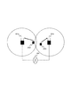
図1は、再送パケットと新規送信パケットの空間多重の問題点を模式的に説明した図である。
以下、上述のような課題について、図1を用いて具体的に説明する。
あるサブフレームT1において、基地局がデータパケットAおよびBをMCW−MIMOにより伝送し、端末ではAのみ受信完了し、Bは再送が必要となったとする。
この場合、基地局は、サブフレームT1+8において、Bの再送パケットと、新規送信パケットCとをMCW−MIMOにより伝送する。
その結果、端末でBのみ受信完了し、Cは再送が必要となったとすると、サブフレームT1+16において、Cの再送パケットと、新規送信パケットDとをMCW−MIMOにより伝送する。
このような状況が続くと、基地局は8サブフレームおきに再送パケットと新規送信パケットのMCW−MIMO送信を繰り返すことになり、結果的に相手の端末がリソースを占有し続ける状態になる。
特に、複数HARQプロセスで上記の状況が発生した場合には、特定の端末が複数のリソースを占有し続けるため、他の端末への送信機会が大きく減少することになる。なお、本発明が解決すべき課題は、再送プロセスが2個以上存在するものであれば、通信方式に関してMCW−MIMO、SISO、SCW−MIMOに限るものではなく、再送方式に関してHARQに限るものではなく、各種の通信方式及び/又は再送方式に適用可能である。
FIG. 1 is a diagram schematically illustrating the problem of spatial multiplexing of retransmission packets and new transmission packets.
Hereinafter, the above problems will be described in detail with reference to FIG.
Assume that in a certain subframe T1, the base station transmits data packets A and B by MCW-MIMO, and the terminal has completed reception of only A, and B needs to be retransmitted.
In this case, the base station transmits the B retransmission packet and the new transmission packet C by MCW-MIMO in subframe T1 + 8.
As a result, if only B is received at the terminal and C needs to be retransmitted, C retransmission packet and new transmission packet D are transmitted by MCW-MIMO in subframe T1 + 16.
If such a situation continues, the base station repeats MCW-MIMO transmission of retransmission packets and new transmission packets every 8 subframes, and as a result, the partner terminal continues to occupy resources.
In particular, when the above situation occurs in a plurality of HARQ processes, since a specific terminal continues to occupy a plurality of resources, transmission opportunities to other terminals are greatly reduced. Note that the problem to be solved by the present invention is not limited to MCW-MIMO, SISO, and SCW-MIMO regarding the communication scheme as long as there are two or more retransmission processes, but not limited to HARQ regarding the retransmission scheme. And applicable to various communication systems and / or retransmission systems.
以上の点に鑑み、本発明の代表的な目的の一つとして、下り信号の再送に必要な周波数・時間リソース量を削減することが挙げられる。
また、本発明の他の代表的な目的として、端末間の送信機会の公平性を確保することが挙げられる。
In view of the above points, one of the typical purposes of the present invention is to reduce the amount of frequency / time resources necessary for retransmission of downlink signals.
Another representative object of the present invention is to ensure fairness of transmission opportunities between terminals.
上記の課題を解決するために、本発明に係る基地局装置は、例えば、再送処理が互いに独立して行われる複数の下り信号を多重化して、同一の端末に(同時に)再送することを特徴とする。
本発明では、前記再送された複数の下り信号をそれぞれ復号するための複数の制御信号を、前記同一の端末に対して同時に送信することができる。この場合、前記複数の制御信号に共通して、前記同一の端末に割り当てる無線資源、および前記複数の下り信号の多重化のための行列演算に使用する行列を指定することができる。また、前記複数の制御信号は、複数のデータのそれぞれに対する新規送信か再送かの判別情報を有し、再送データに対して新規送信と同じデータ番号を指定し、該データ番号のデータに対する前記判別情報を、再送を意味する値に設定し、他のデータ番号のデータに対する前記判別情報を、新規送信を意味する値に設定することができる。さらに、前記複数の下り信号を伝送するための複数の搬送波が存在し、前記複数の制御信号は、前記複数の下り信号のそれぞれの再送処理を識別するための識別子を有し、前記識別子は、前記複数の搬送波の間で一意に付番されるようにしてもよい。
本発明では、前記再送された複数の下り信号をそれぞれ復号するための単一の制御信号を、前記同一の端末に対して同時に送信することができる。この場合、前記単一の制御信号は、前記複数の下り信号のそれぞれの再送処理を識別するための識別子を有することができる。また、前記複数の下り信号を伝送するための複数の搬送波が存在し、前記識別子は、前記複数の搬送波の間で一意に付番されるようにしてもよい。
なお、前記複数の下り信号に優先度を付与し、優先度の高いものから順に選択するようにしてもよい。
In order to solve the above problem, the base station apparatus according to the present invention is characterized in that, for example, a plurality of downlink signals for which retransmission processing is performed independently of each other are multiplexed and retransmitted (simultaneously) to the same terminal. And
In the present invention, a plurality of control signals for decoding the retransmitted downlink signals can be simultaneously transmitted to the same terminal. In this case, in common with the plurality of control signals, it is possible to designate a radio resource to be allocated to the same terminal and a matrix used for matrix calculation for multiplexing the plurality of downlink signals. In addition, the plurality of control signals have information for determining whether to perform new transmission or retransmission for each of a plurality of data, specify the same data number as the new transmission for the retransmission data, and determine the data for the data with the data number. The information can be set to a value meaning retransmission, and the discrimination information for data of other data numbers can be set to a value meaning new transmission. Furthermore, there are a plurality of carriers for transmitting the plurality of downlink signals, the plurality of control signals have identifiers for identifying retransmission processes of the plurality of downlink signals, and the identifiers are: The number may be uniquely assigned among the plurality of carriers.
In the present invention, a single control signal for decoding each of the retransmitted downlink signals can be simultaneously transmitted to the same terminal. In this case, the single control signal may have an identifier for identifying each retransmission process of the plurality of downlink signals. Further, there may be a plurality of carriers for transmitting the plurality of downlink signals, and the identifier may be uniquely assigned among the plurality of carriers.
Note that priority may be given to the plurality of downlink signals, and the signals may be selected in descending order of priority.
また、本発明に係る端末装置は、例えば、再送処理が互いに独立して行われる複数の下り信号が多重化され同一の基地局から再送された再送信号を受信することを特徴とする。
前記複数の下り信号をそれぞれ復号するための複数の制御信号を、前記同一の基地局から(同時に)受信することができる。また、前記複数の制御信号は、前記複数の下り信号のそれぞれに対する新規送信か再送かの判別情報を有し、前記判別情報が再送を示す下り信号のみを復号することができる。また、前記複数の制御信号は、下り制御チャネル番号を有する下り制御チャネルにより伝送され、前記下り制御チャネル番号が最も小さい下り制御チャネルにより伝送された制御信号を参照して受信処理を行った再送データの受信確認情報を、該制御信号で指定されたデータ番号に対応するビットに載せて前記基地局に送信することができる。さらに、前記複数の下り信号をそれぞれ復号するための単一の制御信号を、前記同一の基地局から同時に受信することができる。
In addition, the terminal device according to the present invention is characterized in that, for example, a plurality of downlink signals for which retransmission processing is performed independently of each other are multiplexed and retransmitted from the same base station.
A plurality of control signals for decoding the plurality of downlink signals can be received (simultaneously) from the same base station. In addition, the plurality of control signals have determination information on whether each of the plurality of downlink signals is newly transmitted or retransmitted, and only the downlink signal indicating that the determination information indicates retransmission can be decoded. In addition, the plurality of control signals are transmitted by a downlink control channel having a downlink control channel number, and retransmission data subjected to reception processing with reference to the control signal transmitted by the downlink control channel having the smallest downlink control channel number Can be transmitted on the bit corresponding to the data number specified by the control signal to the base station. Furthermore, a single control signal for decoding each of the plurality of downlink signals can be simultaneously received from the same base station.
本発明によれば、再送処理が互いに独立して行われる複数の下り信号を多重化して、同一の端末に同時に再送することにより、2個のデータパケットの空間多重が可能な伝搬状況であっても1個のデータパケットしか再送できないという事態を回避し、再送に必要な周波数・時間リソース量を削減することができる。
また、本発明によれば、削減した再送用リソースは、他の端末に割り当てることが可能になるため、端末間の送信機会の公平性を確保することができる。
According to the present invention, it is a propagation situation in which two data packets can be spatially multiplexed by multiplexing a plurality of downlink signals that are retransmitted independently and retransmitting them simultaneously to the same terminal. In addition, it is possible to avoid a situation in which only one data packet can be retransmitted, and to reduce the amount of frequency / time resources required for retransmission.
Also, according to the present invention, the reduced retransmission resources can be allocated to other terminals, so that fairness of transmission opportunities between terminals can be ensured.
A.第1の実施の形態
1.フレーム構成
本発明を適用した第1の実施の形態について、図2から図20を用いて説明する。
図2に、セルラ無線通信システムの構成図を示す。
セルラ通信システムは、一般には、図2に示すように、複数の基地局装置と複数の端末装置から構成される。基地局装置201a、201bはそれぞれ、有線回線によってネットワーク203に接続される。端末装置202a、202bは無線回線によってそれぞれ基地局装置201a、201bに接続し、ネットワーク203との通信が可能な仕組みになっている。
なお、基地局装置201aと201bの構成や動作は同一であるため、以下では基地局装置201と総称する。同様に、端末装置202aと202bは端末装置202と総称する。
A. First embodiment
1. Frame Configuration A first embodiment to which the present invention is applied will be described with reference to FIGS.
FIG. 2 shows a configuration diagram of the cellular radio communication system.
A cellular communication system is generally composed of a plurality of base station apparatuses and a plurality of terminal apparatuses as shown in FIG. Each of the
In addition, since the structure and operation | movement of
以下では、無線回線は、LTEの仕様に準拠するものとして説明するが、LTEに限られない。なお、LTEの無線回線の仕様の詳細は、例えば、非特許文献1に規定されている。
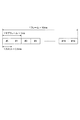
図3に、LTEの無線フレーム構成を示す。
LTEの無線フレームは10msであり、無線フレームを10分割したサブフレーム(1ms)ごとにデータパケットが送信される。1つのサブフレームは、さらに長さ0.5msで6または7OFDMシンボルからなるスロット2個に分かれており、スロット単位で周波数ホッピングを行うことが可能となっている。
図4に、LTEのリソースブロックの構成図を示す。
ここで、図4に示すような、1スロットにおける連続12本の副搬送波からなる無線リソースは、リソースブロック(RB)と呼ばれる。また、1OFDMシンボルおよび1本の副搬送波からなる、無線リソースの最小単位は、リソースエレメント(RE)と呼ばれる。
図5に、LTEの物理チャネルの配置を示す。
サブフレームの先頭の1ないし4OFDMシンボルからなる領域(以下では下り制御領域と呼ぶ)には、下り制御領域が占有するOFDMシンボル数を通知する物理チャネル、上りデータパケット送信に対する基地局からのACK/NAKを伝送する物理チャネル、および下り制御情報(下りデータパケットの受信に必要な情報、上りデータパケットの送信に必要な情報、上り送信電力指示のいずれか)を伝送するための物理チャネルが配置される。
このうち、下り制御情報を送信するための物理チャネルを、以下では下り制御チャネルと呼ぶ。
下り制御チャネルは、36REからなるCCE(Control Channel Element)を単位としている。
端末は、下り制御領域の中の下り制御チャネルが配置される部分のうち、基地局から付与された端末識別番号に応じて決められた範囲の復号を試みる。
その結果、復号に成功したCCEが存在すれば、当該CCEに含まれる下り制御情報を参照する。
なお、以下では、下りデータパケット伝送を考えるため、「下り制御情報」は下りデータパケットの受信に必要な情報を指すものとする。
下り制御領域に後続するサブフレーム末尾までの領域は、各端末が共通に使用でき、下りデータパケットを伝送するための物理チャネルはこの領域に配置される。
以下では上記物理チャネルを下り共有チャネルと呼ぶ。
各々の下り共有チャネルには、連続する12本の副搬送波、すなわちRBの周波数リソース量を最小単位とする周波数リソースが基地局のスケジューラによって割り当てられる。また、例えば1サブフレーム(2スロット)単位での時間リソースの割当が行われる。このため、下り共有チャネルが占有するリソース量は、しばしばRB数により表現される。
In the following description, the wireless line is described as conforming to the LTE specification, but is not limited to LTE. The details of the specifications of the LTE radio line are defined in
FIG. 3 shows an LTE radio frame configuration.
The LTE radio frame is 10 ms, and a data packet is transmitted every subframe (1 ms) obtained by dividing the radio frame into ten. One subframe is further divided into two slots of 0.5 ms in length and consisting of 6 or 7 OFDM symbols, and frequency hopping can be performed in slot units.
FIG. 4 shows a configuration diagram of LTE resource blocks.
Here, as shown in FIG. 4, a radio resource composed of 12 consecutive subcarriers in one slot is called a resource block (RB). Further, the minimum unit of radio resources composed of one OFDM symbol and one subcarrier is called a resource element (RE).
FIG. 5 shows the arrangement of LTE physical channels.
In a region composed of 1 to 4 OFDM symbols at the head of a subframe (hereinafter referred to as a downlink control region), a physical channel for reporting the number of OFDM symbols occupied by the downlink control region, an ACK / from the base station for uplink data packet transmission A physical channel for transmitting a NAK and a physical channel for transmitting downlink control information (information necessary for receiving a downlink data packet, information necessary for transmitting an uplink data packet, or an uplink transmission power instruction) are arranged. The
Among these, a physical channel for transmitting downlink control information is hereinafter referred to as a downlink control channel.
The downlink control channel is based on a CCE (Control Channel Element) composed of 36 REs.
The terminal attempts to decode a range determined according to the terminal identification number assigned from the base station, in the portion where the downlink control channel is arranged in the downlink control region.
As a result, if there is a CCE successfully decoded, the downlink control information included in the CCE is referred to.
In the following, since downlink data packet transmission is considered, “downlink control information” refers to information necessary for receiving downlink data packets.
The area up to the end of the subframe following the downlink control area can be used in common by each terminal, and the physical channel for transmitting downlink data packets is arranged in this area.
Hereinafter, the physical channel is referred to as a downlink shared channel.
Each downlink shared channel is assigned by the scheduler of the base station a frequency resource whose minimum unit is the frequency resource amount of 12 consecutive subcarriers, that is, RBs. For example, time resources are allocated in units of 1 subframe (2 slots). For this reason, the amount of resources occupied by the downlink shared channel is often expressed by the number of RBs.
2.下り制御情報及び通信シーケンス
図6に、データパケットのMCW−MIMO伝送の際に、基地局から端末に送信される下り制御情報の例を示す。
下り制御情報は、リソース割当情報(RB index)、プロセスID(Process ID)、Swap、NDI(New Data Indicator)、MCS、RV(Redundancy Version)、PMI(Precoder Matrix Index)の各フィールドを有する。
リソース割当情報は、該当する下り共有チャネルに割り当てられるRBの数および周波数方向の位置を表す。
プロセスIDは、該当するデータパケットが属するHARQプロセスの識別番号であり、0から7までの値をとる。(この例では、P1として示している。)
Swapは、データパケット(Packet 1、Packet 2)とMCW−MIMOのレイヤとの対応関係を表し、値が0であれば、第1データパケットと第1レイヤ、第2データパケットと第2レイヤがそれぞれ対応する。
また、Swapの値が1であれば、第1データパケットと第2レイヤ、第2データパケットと第1レイヤがそれぞれ対応する。
NDIは、該当するデータパケットの送信が新規送信と再送のどちらであるかを表す1ビットの識別情報であり、新規送信の場合には、同じHARQプロセスで前回送信したときのNDIのビットを反転させ、再送の場合にはビット反転を行わない。
MCSは、データパケットに適用されるMCS番号を表す。MCS番号は、例えば、非特許文献3の表7.1.7.1−1に定義されている。
RVは、該当するデータパケットにおいて誤り訂正符号化されたデータのどの部分を送信するかを表し、0から3までの値をとる。
PMIは、データパケットを空間多重する際の行列演算(プリコーディング)に用いられるプリコーディング行列番号を表す。プリコーディング行列番号は、例えば、非特許文献2の表5.3.3.1.5−4および5.3.3.1.5−5に定義されている。
MCW−MIMOの場合、MCS、NDIおよびRVは2個のデータパケットそれぞれについて指定される。
その他のフィールドは、2個のデータパケットで共通である。
2. Downlink Control Information and Communication Sequence FIG. 6 shows an example of downlink control information transmitted from a base station to a terminal during MCW-MIMO transmission of a data packet.
The downlink control information includes fields for resource allocation information (RB index), process ID (Process ID), Swap, NDI (New Data Indicator), MCS, RV (Redundancy Version), and PMI (Precoder Matrix Index).
The resource allocation information represents the number of RBs allocated to the corresponding downlink shared channel and the position in the frequency direction.
The process ID is an identification number of the HARQ process to which the corresponding data packet belongs, and takes a value from 0 to 7. (In this example, it is indicated as P1.)
Swap represents the correspondence between the data packet (
If the value of Swap is 1, the first data packet corresponds to the second layer, and the second data packet corresponds to the first layer.
NDI is 1-bit identification information indicating whether transmission of the corresponding data packet is new transmission or retransmission. In the case of new transmission, the NDI bit at the time of previous transmission in the same HARQ process is inverted. In the case of retransmission, bit inversion is not performed.
MCS represents the MCS number applied to the data packet. The MCS number is defined in, for example, Table 7.1.7-1-1 of
RV represents which part of data subjected to error correction coding in a corresponding data packet is transmitted, and takes a value from 0 to 3.
PMI represents a precoding matrix number used for matrix operation (precoding) when spatially multiplexing data packets. The precoding matrix number is defined in Tables 5.3.3.1.5-4 and 5.3.3.3.1.5-5 of
For MCW-MIMO, MCS, NDI and RV are specified for each of two data packets.
The other fields are common to the two data packets.
図7に、単一のHARQプロセスにおける下りデータパケット送信のシーケンス図を示す。
まず、あるサブフレームTにおいて、基地局201はデータパケットAおよびBを、MCW−MIMOにより端末202に送信し、同時に、AおよびBの復号に必要な情報を含む下り制御情報を端末202に送信する(ステップ701)。これらのデータパケットおよび下り制御情報を受信した端末202は、サブフレームT+4において、ACK/NAK情報を基地局201に送信する(ステップ702)。
ステップ702にて送信されるACK/NAK情報の内容が、データパケットAおよびBのいずれもACKであった場合には、AおよびBの送信は完了する。
図7(a)のように、データパケットAおよびBのいずれもNAKであった場合には、基地局201は、T+4より後のあるサブフレームT’において、ステップ701と同様にして、データパケットAおよびBを、MCW−MIMOにより端末202に再送し、同時に下り制御情報を端末202に送信する(ステップ703a)。これらのデータパケットおよび下り制御情報を受信した端末202は、サブフレームT’+4において、ACK/NAK情報を基地局201に送信する(ステップ704a)。
図7(b)のように、データパケットAまたはBのいずれか一方がNAKであった場合には、基地局201は、T+4より後のあるサブフレームT”において、NAKとなったデータパケットを、端末202に再送する。このとき、再送するデータパケットとは異なる新規のデータパケットを、再送するデータパケットとともに、MCW−MIMOにより送信しても良い。また、これらのデータパケットと同時に、当該データパケットの復号に必要な下り制御情報を、端末202に送信する(ステップ703b)。これらのデータパケットおよび下り制御情報を受信した端末202は、サブフレームT”+4において、ACK/NAK情報を基地局201に送信する(ステップ704b)。
FIG. 7 shows a sequence diagram of downlink data packet transmission in a single HARQ process.
First, in a certain subframe T,
If the contents of the ACK / NAK information transmitted at
As shown in FIG. 7A, when both of the data packets A and B are NAK, the
As shown in FIG. 7B, when either one of the data packets A or B is NAK, the
図8に、二つのHARQプロセスにおける下りデータパケット送信のシーケンス図を示す。
まず、HARQプロセスP1では、あるサブフレームT1において、基地局201が、データパケットAおよびBを、MCW−MIMOにより端末202に送信し、同時に、AおよびBの復号に必要な情報を含む、一つの下り制御情報を、端末202に送信する(ステップ801)。
なお、ここでは、ステップ801において、データパケットAを第1データパケットとして第1レイヤで伝送し、データパケットBを第2データパケットとして第2レイヤで伝送するものとする。
ステップ801において上記のデータパケットおよび下り制御情報を受信した端末202は、サブフレームT1+4において、ACK/NAK情報を基地局201に送信する(ステップ803)。
一方、HARQプロセスP2では、サブフレームT1とは異なるサブフレームT2において、基地局201が、データパケットCおよびDを、MCW−MIMOにより端末に送信し、同時に、CおよびDの復号に必要な情報を含む、一つの下り制御情報を、端末202に送信する(ステップ802)。
なお、ここでは、ステップ802において、データパケットCを第1データパケットとして第1レイヤで伝送し、データパケットDを第2データパケットとして第2レイヤで伝送するものとする。
ステップ802において上記のデータパケットおよび下り制御情報を受信した端末202は、サブフレームT2+4において、ACK/NAK情報を基地局201に送信する(ステップ804)。
FIG. 8 shows a sequence diagram of downlink data packet transmission in two HARQ processes.
First, in the HARQ process P1, in a certain subframe T1, the
Here, in
The terminal 202 that has received the data packet and the downlink control information in
On the other hand, in the HARQ process P2, in the subframe T2 different from the subframe T1, the
Here, in
The terminal 202 that has received the data packet and the downlink control information in
図9に、ステップ801および802にて送信される下り制御情報の例を示す。
図9(a)はステップ801にて送信される下り制御情報であり、プロセスIDがP1、Swapが0、第1データパケットのNDIが1、第1データパケットのMCSおよびRVがデータパケットAに適用されるMCS番号およびRV、第2データパケットのNDIが1、第2データパケットのMCSおよびRVがデータパケットBに適用されるMCS番号およびRVに、それぞれ設定されている。
図9(b)はステップ802にて送信される下り制御情報であり、プロセスIDがP2、Swapが0、第1データパケットのNDIが1、第1データパケットのMCSおよびRVがデータパケットCに適用されるMCS番号およびRV、第2データパケットのNDIが1、第2データパケットのMCSおよびRVがデータパケットDに適用されるMCS番号およびRVに、それぞれ設定されている。
なお、図9(a)と(b)ではリソース割当およびPMIが同一の値となっているが、これらは異なる値でも良い。
ステップ802または804のいずれかにて送信されるACK/NAK情報の内容が、2つのデータパケットのいずれもACKであった場合には、該当するHARQプロセスにおけるデータパケット送信は完了する。このとき、他方のHARQプロセスの動作は、対応するACK/NAK情報の内容が、少なくとも1つのデータパケットについてNAKであった場合には、ステップ703aもしくは703bに従う。
次に、ステップ803にて送信されるACK/NAK情報の内容が、データパケットAおよびBのいずれか一方がACK、他方がNAKであり、かつ、ステップ804にて送信されるACK/NAK情報の内容が、データパケットCおよびDのいずれか一方がACK、他方がNAKであった場合を考える。
ここでは仮に、データパケットAおよびCがACK、BおよびDがNAKであったとする。
この場合、基地局201は、ステップ803および804が完了した後のあるサブフレームT3において、データパケットBおよびDを、MCW−MIMOにより端末に再送する。
同時に、基地局201は、データパケットBの復号に必要な情報を含む下り制御情報と、データパケットDの復号に必要な情報を含む下り制御情報を、端末202に送信する(ステップ805)。すなわち、ステップ805では、データパケットと二つの下り制御情報を送信する。
なお、ここでは、ステップ805において、データパケットBを第1レイヤで伝送し、データパケットDを第2レイヤで伝送するものとする。
FIG. 9 shows an example of downlink control information transmitted in
FIG. 9A shows the downlink control information transmitted in
FIG. 9B shows the downlink control information transmitted in
9A and 9B, the resource allocation and the PMI have the same value, but these values may be different.
When the contents of the ACK / NAK information transmitted in either step 802 or 804 are both ACK, the data packet transmission in the corresponding HARQ process is completed. At this time, the operation of the other HARQ process follows
Next, the content of the ACK / NAK information transmitted in
Here, it is assumed that data packets A and C are ACK and B and D are NAK.
In this case,
At the same time, the
Here, in
図10に、ステップ805にて送信される二つの下り制御情報の例を示す。
図10(a)では、プロセスIDがP1、Swapが1、第1データパケットのNDIが0、第2データパケットのNDIが1、第2データパケットのMCSおよびRVがデータパケットBに適用されるMCS番号およびRVに、それぞれ設定されている。第1データパケットのMCSおよびRVには、ダミーの値が設定されている。
図10(b)では、プロセスIDがP2、Swapが0、第1データパケットのNDIが0、第2データパケットのNDIが1、第2データパケットのMCSがデータパケットDに適用されるMCS番号に、それぞれ設定されている。第1データパケットのMCSおよびRVには、ダミーの値が設定されている。
なお、図10(a)でデータパケットBのMCS番号およびRVを第2データパケットのフィールドに設定しているのは、LTEではMCW−MIMOにおけるデータパケット番号は新規送信時と再送時で同一にする必要があるためである。
また、図10(a)では、第2データパケットであるデータパケットBを第1レイヤで送信するために、Swapを1に設定している。図10(b)についても、同様の規則に従ってデータパケット番号およびSwapの値が決定される。
図10(a)および(b)のリソース割当およびPMIは、同一の値を設定する。
ステップ805において上記のデータパケットおよび下り制御情報を受信した端末202は、サブフレームT3+4において、ACK/NAK情報を基地局201に送信する(ステップ806)。
ステップ806では、2個のデータパケットの復号結果を表す2ビットのACK/NAK情報が1個だけ送信される。
ここで、2ビットのACK/NAK情報の生成規則は以下の通りである。
ステップ805にて受信した下り制御情報のうち、下り制御チャネル番号の小さな下り制御チャネルにより伝送されたものを参照して復号した再送パケットのACKまたはNAKは、2ビットのACK/NAK情報の中の、当該パケットのデータパケット番号に対応するビットに設定される。
2ビットのACK/NAK情報の中の残りのビットには、もう一方の下り制御チャネルにより伝送されたものを参照して復号した再送パケットのACKまたはNAKが設定される。
FIG. 10 shows an example of two pieces of downlink control information transmitted at
In FIG. 10A, the process ID is P1, the Swap is 1, the NDI of the first data packet is 0, the NDI of the second data packet is 1, and the MCS and RV of the second data packet are applied to the data packet B. MCS number and RV are set respectively. Dummy values are set in MCS and RV of the first data packet.
In FIG. 10B, the process ID is P2, Swap is 0, NDI of the first data packet is 0, NDI of the second data packet is 1, and MCS of the second data packet is applied to the data packet D. Respectively. Dummy values are set in MCS and RV of the first data packet.
In FIG. 10A, the MCS number and RV of data packet B are set in the field of the second data packet. In LTE, the data packet number in MCW-MIMO is the same for new transmission and retransmission. It is necessary to do.
In FIG. 10A, Swap is set to 1 in order to transmit data packet B, which is the second data packet, in the first layer. Also in FIG. 10B, the data packet number and the value of Swap are determined according to the same rule.
The resource allocation and the PMI in FIGS. 10A and 10B are set to the same value.
The terminal 202 that has received the data packet and the downlink control information in
In
Here, the generation rule of 2-bit ACK / NAK information is as follows.
Of the downlink control information received in
In the remaining bits in the 2-bit ACK / NAK information, an ACK or NAK of a retransmission packet decoded with reference to the one transmitted by the other downlink control channel is set.
図11に、ステップ805において図10に示す下り制御情報およびデータパケットを受信したときのACK/NAK情報の生成方法を模式的に示す。
図10(a)を伝送する下り制御チャネル番号の方が小さいとすると、図10(a)を参照して復号されるデータパケットBに該当する第2データパケットに対応するビットに、データパケットBのACKまたはNAKが設定され、残りの第1データパケットに対応するビットに、データパケットDのACKまたはNAKが設定される。
FIG. 11 schematically shows a method for generating ACK / NAK information when the downlink control information and data packet shown in FIG. 10 are received in
If the downlink control channel number for transmitting FIG. 10 (a) is smaller, the data packet B is transferred to the bit corresponding to the second data packet corresponding to the data packet B decoded with reference to FIG. 10 (a). ACK or NAK is set, and ACK or NAK of the data packet D is set in bits corresponding to the remaining first data packets.
なお、端末装置によっては、一つのサブフレームにおいて1個の下り制御情報しか受信しない可能性もある。
そのような端末装置における、ステップ805のデータパケットおよび2個の下り制御情報の受信について、以下で説明する。
端末装置は、サブフレームT3において、下り制御チャネル番号の小さい順に、下り制御チャネルの復号を試み、復号に成功した下り制御チャネルが存在すれば、その時点で下り制御チャネルの復号処理を終了する。
次に、復号された1個の下り制御チャネルに含まれる下り制御情報を参照し、下り共有チャネルにて伝送された2個のデータパケットの復号処理を行う。
このとき、参照される下り制御情報には、一方のデータパケットについては正しいMCSおよびRVが設定されているため、当該パケットの復号処理を行うことができる。
しかし、もう一方のデータパケットについてはダミーのMCSおよびRVが設定されているため、正しく復号処理を行うことができない。
この結果、正しいMCSおよびRVが設定されているパケットについては、2ビットのACK/NAK情報の中の当該パケット番号に対応するビットに、復号結果に応じてACKまたはNAKが設定される。
また、ダミーのMCSおよびRVが設定されているパケットについては、2ビットのACK/NAK情報の中の当該パケット番号に対応するビットに、常にNAKが設定される。
Depending on the terminal device, there is a possibility that only one downlink control information is received in one subframe.
The reception of the data packet and the two pieces of downlink control information in
In the subframe T3, the terminal device attempts to decode the downlink control channel in ascending order of the downlink control channel number. If there is a downlink control channel that has been successfully decoded, the terminal device ends the downlink control channel decoding process at that time.
Next, with reference to downlink control information included in one decoded downlink control channel, decoding processing of two data packets transmitted on the downlink shared channel is performed.
At this time, since the correct MCS and RV are set for one data packet in the downlink control information referred to, the packet can be decoded.
However, since the dummy data MCS and RV are set for the other data packet, the decoding process cannot be performed correctly.
As a result, for a packet for which correct MCS and RV are set, ACK or NAK is set in the bit corresponding to the packet number in the 2-bit ACK / NAK information according to the decoding result.
For a packet in which dummy MCS and RV are set, NAK is always set in a bit corresponding to the packet number in 2-bit ACK / NAK information.
図12に、ステップ805において図10(a)に示すひとつの下り制御情報およびデータパケットを受信したときのACK/NAK情報の生成方法を模式的に示す。
図10(a)を伝送する下り制御チャネル番号の方が小さいとすると、端末装置202では図10(a)のみが参照され、データパケットBのみ復号処理が行われる。
その結果、データパケットBに該当する第2データパケットに対応するビットに、データパケットBのACKまたはNAKが設定され、残りの第1データパケットに対応するビットにはNAKが設定される。
FIG. 12 schematically shows a generation method of ACK / NAK information when one downlink control information and data packet shown in FIG.
If the downlink control channel number for transmitting FIG. 10A is smaller, only the data packet B is decoded in the
As a result, the ACK or NAK of the data packet B is set in the bit corresponding to the second data packet corresponding to the data packet B, and the NAK is set in the bits corresponding to the remaining first data packet.
ここで、図11と図12を比較すると、2ビットのACK/NAK情報はいずれも、データパケットDについてのACKもしくはNAKが、第1データパケットに対応するビットに、またデータパケットBについてのACKもしくはNAKが、第2データパケットに対応するビットに、それぞれ設定されている。
このため、2ビットのACK/NAK情報を受信した基地局装置201は、端末装置が一つのサブフレームにおいて2個の下り制御情報を受信するか否かに関係なく、データパケットBおよびDについて、次の再送動作を行うことができる。
Here, comparing FIG. 11 and FIG. 12, any two-bit ACK / NAK information indicates that the ACK or NAK for the data packet D is changed to the bit corresponding to the first data packet and the ACK for the data packet B. Alternatively, NAK is set for each bit corresponding to the second data packet.
For this reason, the
3.装置構成及び動作フロー
以下、図8から図11までに述べた動作を実現するための、基地局装置201および端末装置202の構成と動作フローについて、図13から図20までを用いて説明する。
3. Device Configuration and Operation Flow Hereinafter, the configurations and operation flows of the
3−1.基地局
図13は、基地局装置201の構成を示すブロック図である。
基地局装置201は、アンテナ1300、RF処理部1310、物理層処理部1320、L2処理部1330、上位層処理部1340、ネットワークインタフェース1350を備える。
RF処理部1310は、搬送波帯の信号の変復調を行う処理部であり、例えば特許文献1の図8におけるRF処理部502と同じ構成をとることができる。
物理層処理部1320は、物理層においてベースバンド信号処理を行う処理部であり、少なくとも下り制御チャネル送信処理部1321、下り共有チャネル送信処理部1322、上り制御チャネル受信処理部1323を備える。
L2処理部1330は、OSI参照モデルの第2層(データリンク層)における信号処理を行う処理部であり、少なくとも、スケジューラ1331、送信バッファ1332およびACK/NAK判定処理部1333を備える。
上位層処理部1340は、OSI参照モデルの第3層(ネットワーク層)以上の階層における信号処理を行う処理部である。
ネットワークインタフェース1350は、基地局装置201がネットワーク203に接続された他の装置と通信を行うためのインタフェースである。
3-1. Base Station FIG. 13 is a block diagram showing the configuration of the
The
The
The physical
The
The upper
The
図14に、スケジューラ1331の動作フローを示す。
スケジューラ1331は、サブフレーム毎に、自局に接続している端末の中から、スケジューリング対象となる端末を選択する(ステップ1401)。
端末の選択方法としては、例えば非特許文献4に記載のプロポーショナル・フェアネス法の適用が考えられる。
ステップ1401が完了すると、ステップ1401において選択された端末全てについて、以下の動作を繰り返す。
まず、当該端末への下りデータパケット送信の際に適用するMCS(ステップ1402)、MIMO適用の有無(ステップ1403)、プリコーディング行列(ステップ1404)、および当該端末に割り当てるRBの周波数位置とRB数(ステップ1405)を決定する。つまり、1405では、時間リソースは当該サブフレーム、周波数リソースは当該周波数位置を割当てる。
これらの決定には、端末から通知されるチャネル品質や、MIMOの空間多重度を表すランク情報を参照する。
次に、スケジューラ1331は、送信バッファが保持している送信待ちの当該端末宛データパケットの中から、当該サブフレームにて送信するデータパケットを選択する(ステップ1406)。
ステップ1406の処理の詳細については後述する。
ステップ1406が完了すると、スケジューラ1331は、ステップ1402、1403、1404および1405により決定したMCS、MIMO適用の有無、プリコーディング行列およびRBを通知するための下り制御情報を生成し(ステップ1407)、物理層処理部1320に通知する(ステップ1408)。
FIG. 14 shows an operation flow of the
The
As a terminal selection method, for example, application of the proportional fairness method described in Non-Patent Document 4 can be considered.
When
First, MCS (step 1402) applied when transmitting downlink data packets to the terminal, presence / absence of MIMO application (step 1403), precoding matrix (step 1404), and frequency position and number of RBs assigned to the terminal (Step 1405) is determined. That is, in 1405, the time resource allocates the subframe, and the frequency resource allocates the frequency position.
For these determinations, channel quality notified from the terminal and rank information indicating the spatial multiplicity of MIMO are referred to.
Next, the
Details of the processing in
When
図15に、ステップ1406におけるスケジューラ1331のデータパケット選択処理の動作フローを示す。
なお、ここでは、ステップ1403によって、当該端末への下りデータパケット送信にMIMOを適用することが決定されているものとする。
まず、スケジューラ1331は、当該端末宛の送信待ちデータパケットの中から、再送を必要とするものを探索する(ステップ1501)。
ステップ1501の結果、再送を必要とする送信待ちデータパケット(以下、再送パケット)が存在しない場合には、当該端末宛に新規送信するデータパケットを選択し(ステップ1502)、処理を終了する。
ステップ1501の結果、再送パケットが存在する場合には、その数が2個以上であるか否かを判定し(ステップ1503)、その結果、再送パケットが1個の場合には、当該再送パケットを選択し(ステップ1504)、処理を終了する。なお、ステップ1504では、さらに新規送信パケットを1個選択するようにしてもよい。
ステップ1503の結果、再送パケットが2個以上存在した場合には、これらの再送パケットの間で優先度付けを行う(ステップ1505)。ここで、優先度付けは、新規送信を行った時点からの経過時間が長いものほど優先度を高く設定してもよいし、パケットのデータ量に基づいて優先度を設定してもよいし、パケットの種類に基づいて設定してもよい。
次に、ステップ1505により優先度1位となった再送パケットを前回送信したときにMIMO多重された他の再送パケットが存在するか否かを判定し(ステップ1506)、存在する場合には、当該再送パケット2個を選択し(ステップ1507)、処理を終了する。
ステップ1506の結果、優先度1位の再送パケットを前回送信したときにMIMO多重された他の再送パケットが存在しない場合には、ステップ1505により優先度2位となった再送を前回送信したときにMIMO多重された他の再送パケットが存在するか否かを判定する(ステップ1508)。
ステップ1508の結果、優先度2位の再送パケットを前回送信したときにMIMO多重された他の再送パケットが存在する場合には、優先度1位および2位の再送パケットを1回で再送できないため、優先度1位の再送パケット1個のみを選択し(ステップ1509)、処理を終了する。
ステップ1508の結果、優先度2位の再送パケットを前回送信したときにMIMO多重された他の再送パケットが存在しない場合には、優先度1位および2位の再送パケットを各1個ずつ選択し(ステップ1510)、処理を終了する。
このように、再送パケット間で優先度付けを行うことで、例えば、端末が受信すべきデータを優先的に再送することが可能となる。
FIG. 15 shows an operation flow of data packet selection processing of the
In this case, it is assumed that MIMO is applied to downlink data packet transmission to the terminal in
First, the
If the result of
If it is determined in
If there are two or more retransmission packets as a result of
Next, it is determined whether or not there is another retransmission packet that is MIMO-multiplexed when the retransmission packet having the highest priority in
As a result of
As a result of
As a result of
In this way, by assigning priorities between retransmission packets, for example, data to be received by the terminal can be preferentially retransmitted.
図16に、ステップ1407におけるスケジューラ1331の下り制御情報生成処理の動作フローを示す。
スケジューラ1331は、まず第1の再送プロセスにおけるデータパケットの再送に使用するレイヤを選択し(ステップ1601)、当該データパケットに対応するパケット番号(レイヤ番号)のNDIを前回送信時と同じ値(再送)に(ステップ1602)、もう一方のパケット番号(レイヤ番号)のNDIを前回送信時の値をビット反転した値(新規)に設定する(ステップ1603)。
ステップ1331において選択されたレイヤが、当該データパケットの新規送信に用いられたレイヤと同一である場合には、Swapの値を0とし(ステップ1604)、そうでない場合にはSwapの値を1とする(ステップ1605)。
以上のようにして設定されたSwap、およびステップ1402、1403、1404、1405により決定された値(RB index、Process ID、MCS、RV、PMI)を用いて、第1の下り制御情報を生成する(ステップ1606)。
次にスケジューラ1331は、ステップ1601において第1の再送プロセスの再送用として選択されなかったレイヤを、第2の再送プロセスにおけるデータパケットの再送に使用するレイヤとし(ステップ1607)、当該データパケットに対応するパケット番号のNDIを前回送信時と同じ値(再送)に(ステップ1608)、もう一方のパケット番号のNDIを前回送信時の値をビット反転した値(新規)に設定する(ステップ1609)。
ステップ1607において選択されたレイヤが、当該データパケットの新規送信に用いられたレイヤと同一である場合には、Swapの値を0とし(ステップ1610)、そうでない場合にはSwapの値を1とする(ステップ1611)。
以上のようにして設定されたSwap、およびステップ1402、1403、1404、1405により決定された値(RB index、Process ID、MCS、RV、PMI)を用いて、第2の下り制御情報を生成する(ステップ1612)。
FIG. 16 shows an operation flow of downlink control information generation processing of the
The
If the layer selected in
The first downlink control information is generated using the Swap set as described above and the values (RB index, Process ID, MCS, RV, and PMI) determined in
Next, the
If the layer selected in
The second downlink control information is generated using the Swap set as described above and the values (RB index, Process ID, MCS, RV, and PMI) determined in
3−2.端末
図17は、端末装置202の構成を示すブロック図である。
端末装置202は、アンテナ1700、RF処理部1710、物理層処理部1720、L2処理部1730、上位層処理部1740を備える。
RF処理部1710は、搬送波帯の信号の変復調を行う処理部であり、例えば特許文献1の図9におけるRF処理部602と同じ構成をとることができる。
物理層処理部1720は、物理層においてベースバンド信号処理を行う処理部であり、少なくとも下り制御チャネル受信処理部1721、下り共有チャネル受信処理部1722、上り制御チャネル送信処理部1723を備える。
L2処理部1730は、OSI参照モデルの第2層(データリンク層)における信号処理を行う処理部であり、少なくともデータ再構成処理部1731およびACK/NAK判定処理部1732を備える。
上位層処理部1740は、第3層(ネットワーク層)以上の階層における信号処理を行う処理部である。
3-2. Terminal FIG. 17 is a block diagram showing a configuration of the
The
The
The physical
The
The upper
図18に、下り制御チャネル受信処理部1721のサブフレーム毎の動作フローを示す。
下り制御チャネル受信処理部1721は、新たなサブフレームの処理を開始する際に、下り制御チャネル受信数を0にリセットし(ステップ1801)、下り制御チャネルの復号を試みる(ステップ1802)。
その結果、復号に成功した下り制御チャネルが存在した場合には、復号して得られた情報が自宛の下り制御情報であると判断し、その内容を下り共有チャネル受信処理部1722およびACK/NAK判定処理部1732に通知し(ステップ1803)、下り制御チャネル受信数に1を加える(ステップ1804)。
次いで、下り制御チャネル受信数が2であるか否かを判定し、1であればステップ1802を繰り返す。
下り制御チャネル受信数が2の場合には、下り共有チャネル受信処理部およびACK/NAK判定処理部に下り制御チャネル受信数を通知し(ステップ1805)、処理を終了する。
ステップ1802の結果、復号に成功した下り制御チャネルが存在しない場合には、これまでに得られているもの以外に自宛の下り制御情報が存在しないと判断し、ステップ1805に進む。
FIG. 18 shows an operation flow for each subframe of the downlink control channel
When starting to process a new subframe, the downlink control channel
As a result, when there is a downlink control channel that has been successfully decoded, it is determined that the information obtained by decoding is the downlink control information addressed to itself, and the content is transmitted to the downlink shared channel
Next, it is determined whether the downlink control channel reception number is 2, and if it is 1,
When the downlink control channel reception number is 2, the downlink shared channel reception processing unit and the ACK / NAK determination processing unit are notified of the downlink control channel reception number (step 1805), and the process is terminated.
If there is no downlink control channel that has been successfully decoded as a result of
図19に、ステップ1803において下り制御チャネル受信部から下り制御チャネルの復号結果を通知されたときの、下り共有チャネル受信処理部1722の動作フローを示す。
下り共有チャネル受信処理部1722は、新たなサブフレームの処理を開始する際に、下り制御情報参照回数を0にリセットし(ステップ1901)、ステップ1803にて通知された下り制御チャネルの復号結果を参照する(ステップ1902)。
ここで、下り制御チャネルの復号結果に含まれるSwapの値が0であった場合には、上記復号結果に含まれる第1データパケットのMCS、NDIおよびRVを参照して(ステップ1903a)、該当する下り共有チャネルの第1レイヤを復号し(ステップ1904a)、その結果を第1データパケットの復号結果としてACK/NAK判定処理部1732に通知する(ステップ1905a)。次に、下り制御チャネルの復号結果に含まれる第2データパケットのMCS、NDIおよびRVを参照して(ステップ1906a)、該当する下り共有チャネルの第2レイヤを復号し(ステップ1907a)、その結果を第2データパケットの復号結果としてACK/NAK判定処理部1732に通知する(ステップ1908a)。
一方、下り制御チャネルの復号結果に含まれるSwapの値が1であった場合には、上記復号結果に含まれる第2データパケットのMCS、NDIおよびRVを参照して(ステップ1903b)、該当する下り共有チャネルの第1レイヤを復号し(ステップ1904b)、その結果を第2データパケットの復号結果としてACK/NAK判定処理部1732に通知する(ステップ1905b)。次に、下り制御チャネルの復号結果に含まれる第1データパケットのMCS、NDIおよびRVを参照して(ステップ1906b)、該当する下り共有チャネルの第2レイヤを復号し(ステップ1907b)、その結果を第1データパケットの復号結果としてACK/NAK判定処理部1732に通知する(ステップ1908b)。
ステップ1908aまたは1908bが完了すると、下り共有チャネル受信処理部1722は、下り制御情報参照回数に1を加える(ステップ1909)。
次に、下り制御情報参照回数が、ステップ1805にて下り制御チャネル受信処理部1721から通知された下り制御チャネル受信数と等しければ、処理を終了し、そうでなければステップ1902に戻る。
FIG. 19 shows an operation flow of the downlink shared channel
When starting to process a new subframe, the downlink shared channel
Here, if the value of Swap included in the decoding result of the downlink control channel is 0, the MCS, NDI and RV of the first data packet included in the decoding result are referred to (
On the other hand, when the value of Swap included in the decoding result of the downlink control channel is 1, the MCS, NDI, and RV of the second data packet included in the decoding result are referred to (
When
Next, if the downlink control information reference count is equal to the downlink control channel reception number notified from downlink control channel
図20に、ACK/NAK判定処理部1732の動作フローを示す。
ACK/NAK判定処理部1732は、ステップ1805にて下り制御チャネル受信処理部1721から通知された下り制御チャネル受信数を参照し(ステップ2001)、その値が2であれば、ステップ1803にて下り制御チャネル受信処理部1721から通知された第1の下り制御情報の第1データパケットのNDIを参照し、第1データパケットが再送パケットであるか否かを判定する(ステップ2002)。
ステップ2002の結果、第1データパケットが再送パケットであった場合には、下り共有チャネル受信処理部1722から通知された第1データパケットの復号結果を参照し(ステップ2003)、復号成功であれば1、復号失敗であれば0を、ACK/NAK情報の中の第1データパケットの情報を表すビットに設定する(ステップ2004)。
ステップ2002の結果、第1データパケットが再送パケットでない場合には、
上記第1の下り制御情報の第2データパケットのNDIを参照し、第2データパケットが再送パケットであるか否かを判定する(ステップ2005)。
ステップ2005の結果、第2データパケットが再送パケットであった場合には、下り共有チャネル受信処理部1722から通知された第2データパケットの復号結果を参照し(ステップ2006)、復号成功であれば1、復号失敗であれば0を、ACK/NAK情報の中の第2データパケットの情報を表すビットに設定する(ステップ2007)。
ステップ2004もしくは2007を完了すると、次に、ステップ1803にて下り制御チャネル受信処理部1721から通知された第2の下り制御情報の第1データパケットのNDIを参照し、第1データパケットが再送パケットであるか否かを判定する(ステップ2008)。
ステップ2008の結果、第1データパケットが再送パケットであった場合には、下り共有チャネル受信処理部1722から通知された第1データパケットの復号結果を参照し(ステップ2009)、復号成功であれば1、復号失敗であれば0を、ACK/NAK情報の中の第2データパケットの情報を表すビットに設定する(ステップ2010)。
ステップ2008の結果、第1データパケットが再送パケットでない場合には、上記第2の下り制御情報の第2データパケットのNDIを参照し、第2データパケットが再送パケットであるか否かを判定する(ステップ2011)。
ステップ2011の結果、第2データパケットが再送パケットであった場合には、下り共有チャネル受信処理部1722から通知された第2データパケットの復号結果を参照し(ステップ2012)、復号成功であれば1、復号失敗であれば0を、ACK/NAK情報の中の第1データパケットの情報を表すビットに設定する(ステップ2013)。
ステップ2005もしくは2011において、第2データパケットが再送パケットでない場合には、ACK/NAK情報の中の第1データパケットの情報を表すビット、第2データパケットの情報を表すビットともに0を設定する(ステップ2014)。
ステップ2001の結果、下り制御チャネル受信数が1であった場合には、下り共有チャネル受信処理部1722から通知された第1データパケットの復号結果を参照し(ステップ2015)、復号成功であれば1、復号失敗であれば0を、ACK/NAK情報の中の第1データパケットの情報を表すビットに設定する(ステップ2016)。
次に、下り共有チャネル受信処理部1722から通知された第2データパケットの復号結果を参照し(ステップ2017)、復号成功であれば1、復号失敗であれば0を、ACK/NAK情報の中の第2データパケットの情報を表すビットに設定する(ステップ2018)。
ステップ2010、2013、2014、2018のいずれかが完了すると、これらのステップにより生成されたACK/NAK情報を、上り制御チャネル送信処理部1723に通知し(ステップ2019)、処理を終了する。
FIG. 20 shows an operation flow of the ACK / NAK
The ACK / NAK
As a result of
If the result of
With reference to the NDI of the second data packet of the first downlink control information, it is determined whether or not the second data packet is a retransmission packet (step 2005).
If the result of
When
If the result of
If the result of
As a result of
In
If the number of downlink control channel receptions is 1 as a result of
Next, the decoding result of the second data packet notified from the downlink shared channel
When any one of
なお、ステップ2001で、同一の無線リソースに対するスケジューリングを行う下り制御チャネルが1個か2個かを判断するが、パケット#1及び#2が両方とも新規の場合は、下り制御チャネルが1個になり、ステップ2015〜2018に進む。そのため、下り制御チャネルが2個で、かつパケット#1及び#2がともに新規であった場合は、異常ケースと判断し、ステップ2014で、#1及び#2ともNAKにする。
In
上り制御チャネル送信処理部1723は、ACK/NAK判定処理部から通知されたACK/NAK情報に対し、誤り訂正符号化および変調処理を行う。
これらの処理が施されたACK/NAK情報は、上り制御チャネルにより、RF処理部1711を経由して基地局装置201に送信される。
The uplink control channel
The ACK / NAK information subjected to these processes is transmitted to the
端末装置202から上り制御チャネルを受信した基地局装置201は、上り制御チャネル受信処理部1323において、受信した上り制御チャネルを復号し、その結果得られるACK/NAK情報を、ACK/NAK判定処理部1333に通知する。
ACK/NAK判定処理部1333は、通知されたACK/NAK情報を参照し、ACKを通知されたデータパケットを送信待ち行列から削除する。
The
The ACK / NAK
本実施の形態は、各々のHARQプロセスにおいて2個のデータパケットを送信し、そのうちの1個のみ再送が必要になった場合に、それらの再送を一つのMCW−MIMO伝送に集約することを可能にする。これにより、MCW−MIMOにより伝送されるパケットの再送に必要な時間方向のリソース量を半分程度に削減し、リソース利用効率の向上を図ることができる。
また、本発明の送受信方式をサポートしない端末に対しても、MCW−MIMOで伝送された2個のデータパケットのうちの1個は復号可能であり、かつ上記2個のデータパケットの再送処理の継続が可能である。なお、本実施の形態は、再送プロセスが2個以上存在するものであれば、通信方式に関してMCW−MIMO、SISO、SCW−MIMOに限るものではなく、再送方式に関してHARQに限るものではない。
In the present embodiment, two data packets are transmitted in each HARQ process, and when only one of them needs to be retransmitted, these retransmits can be aggregated into one MCW-MIMO transmission. To. As a result, the amount of resources in the time direction required for retransmission of packets transmitted by MCW-MIMO can be reduced to about half, and resource utilization efficiency can be improved.
Further, even for a terminal that does not support the transmission / reception method of the present invention, one of the two data packets transmitted by MCW-MIMO can be decoded, and the retransmission processing of the two data packets can be performed. It can be continued. Note that this embodiment is not limited to MCW-MIMO, SISO, and SCW-MIMO regarding the communication scheme as long as there are two or more retransmission processes, and is not limited to HARQ regarding the retransmission scheme.
B.第2の実施の形態
本発明を適用した第2の実施の形態について、図21から図26を用いて説明する。
B. Second embodiment
A second embodiment to which the present invention is applied will be described with reference to FIGS.
第2の実施の形態は、第1の実施の形態と比較して、図1に示した、基地局装置201、端末装置202およびネットワーク203からなる全体構成、およびそれらの機器の内部構成は同じであるが、基地局装置201および端末装置202の動作、および基地局装置201と端末装置202との間で送受信される情報が異なっている。
Compared with the first embodiment, the second embodiment has the same overall configuration including the
1.下り制御情報及び送信シーケンス
図21に、二つのHARQプロセスにおける下りデータパケット送信のシーケンス図を示す。
図21は、図8と比較して、ステップ803にて送信されるACK/NAK情報の内容が、MCW−MIMOにより伝送される2個のデータパケットのいずれか一方がACK、他方がNAKであり、かつ、ステップ804にて送信されるACK/NAK情報の内容が、MCW−MIMOにより伝送される2個のデータパケットのいずれか一方がACK、他方がNAKであった場合のシーケンスが異なっている。
1. Downlink Control Information and Transmission Sequence FIG. 21 shows a sequence diagram of downlink data packet transmission in two HARQ processes.
FIG. 21 is different from FIG. 8 in that the content of the ACK / NAK information transmitted in
ここでは仮に、図21の下り制御情報とともにデータパケットAおよびB、CおよびDを、それぞれ別々のHARQプロセスでMCW−MIMOにより伝送し、データパケットAおよびDがACK、BおよびCがNAKであったとする。
この場合、基地局201は、ステップ803および804が完了した後のあるサブフレームT3において、データパケットBおよびCを、MCW−MIMOにより端末202に再送する。
同時に、基地局201は、BおよびCの復号に必要な情報を含む一つの下り制御情報を、端末202に送信する(ステップ2101)。すなわち、ステップ2101では、データパケットと一つの下り制御情報を送信する。
なお、ステップ2101では、データパケットBを第2レイヤで伝送し、データパケットCを第1レイヤで伝送するものとする。
Here, it is assumed that data packets A and B, C, and D are transmitted by MCW-MIMO in separate HARQ processes together with downlink control information of FIG. Suppose.
In this case,
At the same time, the
In
図22に、ステップ2101にて送信される下り制御情報の例を示す。
図22では、Swapが0、第1データパケットのNDIが1、第1データパケットのプロセスIDがP2、第1データパケットのMCSおよびRVがデータパケットCに適用されるMCS番号およびRV、第2データパケットのNDIが1、第2データパケットのプロセスIDがP1、第2データパケットのMCSおよびRVがデータパケットBに適用されるMCS番号およびRVに、それぞれ設定されている。
図22は、図10と比較して、プロセスIDを2個のデータパケットそれぞれについて指定する点が異なる。
FIG. 22 shows an example of downlink control information transmitted in
In FIG. 22, Swap is 0, the NDI of the first data packet is 1, the process ID of the first data packet is P2, the MCS and RV of the first data packet are the MCS number and RV applied to the data packet C, the second The NDI of the data packet is 1, the process ID of the second data packet is P1, and the MCS and RV of the second data packet are set to the MCS number and RV applied to the data packet B, respectively.
FIG. 22 differs from FIG. 10 in that the process ID is designated for each of the two data packets.
ステップ2101において上記のデータパケットおよび下り制御情報を受信した端末202は、サブフレームT3+4において、ACK/NAK情報を基地局201に送信する(ステップ2102)。
The terminal 202 that has received the data packet and the downlink control information in
ステップ2102では、二つのデータパケットの復号結果を表す2ビットのACK/NAK情報が一つだけ送信される。
ここで、2ビットのACK/NAK情報は、ステップ2101にて端末装置201が受信した下り制御情報のパケット番号に対応したビットに、該当するデータパケットのACKもしくはNAKが設定される。
In
Here, in the 2-bit ACK / NAK information, the ACK or NAK of the corresponding data packet is set in the bit corresponding to the packet number of the downlink control information received by the
2.装置構成及び動作フロー
次に、本実施の形態において上記に述べた動作を実現するための、基地局装置201および端末装置202の動作フローについて、図23から図26までを用いて説明する。
2. Device Configuration and Operation Flow Next, the operation flow of the
基地局装置201の構成は図13と同一であり、その中のスケジューラ1331の動作フローは図14と同一であるが、ステップ1407における下り制御情報生成処理の動作が図16と異なる。
The configuration of the
図23に、ステップ1407におけるスケジューラ1331の下り制御情報生成処理の動作フローを示す。
スケジューラ1331は、第1の再送プロセスにおけるデータパケットの再送に使用するレイヤを選択し(ステップ2301)、当該データパケットに対応するパケット番号のNDIを前回送信時と同じ値に設定する(ステップ2302)。
また、ステップ2301において第1の再送プロセスの再送用として選択されなかったレイヤを、第2の再送プロセスにおけるデータパケットの再送に使用するレイヤとし(ステップ2303)、当該データパケットに対応するパケット番号のNDIを前回送信時と同じ値に設定する(ステップ2304)。
ステップ2301および2303にて決定されたレイヤが、いすれも当該データパケットの新規送信に用いられたレイヤと同一である場合には、Swapの値を0とする(ステップ2305)。
また、ステップ2301および2303にて決定されたレイヤが、いすれも当該データパケットの新規送信に用いられたレイヤと異なる場合には、Swapの値を1とする(ステップ2306)。
ステップ2305、2306のいずれかが完了すると、これらのステップにて設定されたSwap、およびステップ1402、1403、1404、1405(RB index、Process ID、MCS、RV、PMI)により決定された値を用いて、1個の下り制御情報を生成する(ステップ2307)。
なお、ステップ2301および2303において決定されたレイヤが、第1および第2の再送プロセスにおいて再送されるデータパケットのいずれか一方のみについて、当該データパケットの新規送信に用いられたレイヤと異なり、他方のデータパケットについては当該データパケットの新規送信に用いられたレイヤと同一である場合には、本実施の形態の方式では対応することができないため、第1の実施の形態と同様に、2個の制御情報を生成する(ステップ2308)。
FIG. 23 shows an operation flow of downlink control information generation processing of the
The
In addition, the layer not selected for retransmission in the first retransmission process in
If the layers determined in
If the layers determined in
When one of
Note that the layer determined in
一方、端末装置202については、構成は図17と同一であるが、下り制御チャネル受信処理部1721、下り共有チャネル受信処理部1722およびACK/NAK判定処理部1732の動作が、第1の実施の形態と異なっている。
On the other hand, the configuration of the
図24に、下り制御チャネル受信処理部1721のサブフレーム毎の動作フローを示す。
下り制御チャネル受信処理部1721は、新たなサブフレームが開始されると、下り制御チャネルの復号を試みる(ステップ2401)。
その結果、復号に成功した下り制御チャネルが存在した場合には、復号して得られた情報が自宛の下り制御情報であると判断し、その内容を下り共有チャネル受信処理部1722およびACK/NAK判定処理部1732に通知して(ステップ2402)、処理を終了する。
ステップ2401の結果、復号に成功した下り制御チャネルが存在しない場合には、自宛の下り制御情報が存在しないと判断し、処理を終了する。
FIG. 24 shows an operation flow for each subframe of the downlink control channel
When a new subframe is started, the downlink control channel
As a result, when there is a downlink control channel that has been successfully decoded, it is determined that the information obtained by decoding is the downlink control information addressed to itself, and the content is transmitted to the downlink shared channel
If there is no downlink control channel that has been successfully decoded as a result of
図25に、ステップ1803において下り制御チャネル受信部から下り制御チャネルの復号結果を通知されたときの、下り共有チャネル受信処理部1722の動作フローを示す。
下り共有チャネル受信処理部1722は、新たなサブフレームが開始されると、ステップ1803にて通知された下り制御チャネルの復号結果を参照する(ステップ2501)。
以降、ステップ1908aもしくは1908bが完了するまでの動作は、図19と同じである。
ステップ1908aもしくは1908bが完了すると、下り共有チャネル受信処理部1722は処理を終了する。
FIG. 25 shows an operation flow of the downlink shared channel
When a new subframe is started, the downlink shared channel
Thereafter, the operation until
When
図26に、ACK/NAK判定処理部1732の動作フローを示す。
ACK/NAK判定処理部1732は、下り共有チャネル受信処理部1722から通知された第1データパケットの復号結果を参照し(ステップ2601)、復号成功であれば1、復号失敗であれば0を、ACK/NAK情報の中の第1データパケットの情報を表すビットに設定する(ステップ2602)。
次に、下り共有チャネル受信処理部1722から通知された第2データパケットの復号結果を参照し(ステップ2603)、復号成功であれば1、復号失敗であれば0を、ACK/NAK情報の中の第2データパケットの情報を表すビットに設定し(ステップ2604)、処理を終了する。
FIG. 26 shows an operation flow of the ACK / NAK
The ACK / NAK
Next, the decoding result of the second data packet notified from the downlink shared channel
本実施の形態は、第1の実施の形態と比較して、複数のHARQプロセスの再送を集約してMCW−MIMO伝送を行う際にも、基地局から端末に送信する下り制御情報は一つで良いため、制御情報の伝送によるオーバヘッドを低減することができる。なお、本実施の形態は、再送プロセスが2個以上存在するものであれば、通信方式に関してMCW−MIMO、SISO、SCW−MIMOに限るものではなく、再送方式に関してHARQに限るものではない。 Compared with the first embodiment, this embodiment has only one downlink control information to be transmitted from the base station to the terminal even when MCW-MIMO transmission is performed by aggregating retransmissions of a plurality of HARQ processes. Therefore, the overhead due to transmission of control information can be reduced. Note that this embodiment is not limited to MCW-MIMO, SISO, and SCW-MIMO regarding the communication scheme as long as there are two or more retransmission processes, and is not limited to HARQ regarding the retransmission scheme.
C.第3の実施の形態
本発明を適用した第3の実施の形態について、図27から図31を用いて説明する。
C. Third embodiment
A third embodiment to which the present invention is applied will be described with reference to FIGS.
第3の実施の形態は、第1の実施の形態と比較して、図1に示した、基地局装置201、端末装置202およびネットワーク203からなる全体構成、およびそれらの機器の内部構成は同じであるが、基地局装置201の動作、および基地局装置201と端末装置202との間で送受信される情報が異なっている。
Compared with the first embodiment, the third embodiment has the same overall configuration including the
1.下り制御情報及び送信シーケンス
図27に、二つのHARQプロセスにおける下りデータパケット送信のシーケンス図を示す。
まず、HARQプロセスP1では、あるサブフレームT1において、基地局201はデータパケットAを端末202に送信し、同時に、データパケットAの復号に必要な情報を含む、一つの下り制御情報を、端末202に送信する(ステップ2701)。
ステップ2701において上記のデータパケットおよび下り制御情報を受信した端末202は、サブフレームT1+4において、ACK/NAK情報を基地局201に送信する(ステップ2703)。
一方、HARQプロセスP2では、サブフレームT1とは異なるサブフレームT2において、基地局201は端末202に対し、データパケットBを端末202に送信し、同時に、データパケットBの復号に必要な情報を含む、一つの下り制御情報を、端末202に送信する(ステップ2702)。
ステップ2702において上記のデータパケットおよび下り制御情報を受信した端末202は、サブフレームT2+4において、ACK/NAK情報を基地局201に送信する(ステップ2704)。
図28に、ステップ2701および2702にて送信される下り制御情報の例を示す。
図28(a)はステップ2701にて送信される下り制御情報であり、プロセスIDがP1、NDIが1、MCSおよびRVがデータパケットAに適用されるMCS番号およびRVに、それぞれ設定されている。
図28(b)はステップ2702にて送信される下り制御情報であり、プロセスIDがP2、NDIが1、MCSおよびRVがデータパケットBに適用されるMCS番号およびRVに、それぞれ設定されている。
なお、図28(a)と(b)ではリソース割当が同一の値となっているが、これらは異なる値でも良い。
ステップ2703および2704にて送信されるACK/NAK情報の内容がいずれもNAKであった場合、基地局201は、ステップ2703および2704が完了した後のあるサブフレームT3において、データパケットAおよびBを、MCW−MIMOにより端末202に再送する。
同時に、基地局201は、Aの復号に必要な情報を含む下り制御情報と、Bの復号に必要な情報を含む下り制御情報とを、端末202に送信する(ステップ2705)。すなわち、ステップ2705では、データパケットと二つの下り制御情報を送信する。
なお、ステップ2705では、データパケットAを第1レイヤで伝送し、データパケットBを第2レイヤで伝送するものとする。
図29に、ステップ2705にて送信される二つの下り制御情報の例を示す。
図29(a)では、プロセスIDがP1、Swapが0、第1データパケットのNDIが1、第1データパケットのMCSおよびRVがデータパケットAに適用されるMCS番号およびRV、第2データパケットのNDIが0に、それぞれ設定されている。第2データパケットのMCSおよびRVには、ダミーの値が設定されている。
図29(b)では、プロセスIDがP2、Swapが0、第1データパケットのNDIが0、第2データパケットのNDIが1、第2データパケットのMCSがデータパケットBに適用されるMCS番号に、それぞれ設定されている。第1データパケットのMCSおよびRVには、ダミーの値が設定されている。
図29(a)および(b)のリソース割当およびPMIは、同一の値を設定する。
ステップ2705において上記のデータパケットおよび下り制御情報を受信した端末202は、サブフレームT3+4において、ACK/NAK情報を基地局201に送信する(ステップ2706)。
ステップ2706では、2個のデータパケットの復号結果を表す2ビットのACK/NAK情報が1個だけ送信される。
ここで、2ビットのACK/NAK情報の生成規則は、第1の実施の形態におけるステップ806とは異なり、二つの下り制御情報を参照して第1データパケットおよび第2データパケットを復号した結果を、そのまま対応するビットに設定する。
1. Downlink Control Information and Transmission Sequence FIG. 27 shows a sequence diagram of downlink data packet transmission in two HARQ processes.
First, in the HARQ process P1, in a certain subframe T1, the
The terminal 202 that has received the data packet and the downlink control information in
On the other hand, in the HARQ process P2, in a subframe T2 different from the subframe T1, the
The terminal 202 that has received the data packet and the downlink control information in
FIG. 28 shows an example of downlink control information transmitted in
FIG. 28A shows downlink control information transmitted in
FIG. 28B shows downlink control information transmitted in
In FIGS. 28A and 28B, the resource allocation is the same value, but these values may be different.
If the contents of the ACK / NAK information transmitted in
At the same time, the
In
FIG. 29 shows an example of the two downlink control information transmitted in
In FIG. 29 (a), the process ID is P1, the Swap is 0, the NDI of the first data packet is 1, the MCS and RV of the first data packet are applied to the data packet A, the RCS, and the second data packet. NDI is set to 0, respectively. Dummy values are set in MCS and RV of the second data packet.
In FIG. 29B, the process ID is P2, Swap is 0, the NDI of the first data packet is 0, the NDI of the second data packet is 1, and the MCS of the second data packet is applied to the data packet B. Respectively. Dummy values are set in MCS and RV of the first data packet.
The resource allocation and the PMI in FIGS. 29A and 29B are set to the same value.
The terminal 202 that has received the data packet and the downlink control information in
In
Here, the generation rule of the 2-bit ACK / NAK information is different from
2.装置構成及び動作フロー
図27から図29までに述べた動作を実現するための、基地局装置201および端末装置202の構成は、第1の実施の形態と同じである。
また、各構成要素の動作フローは、基地局装置201のスケジューラ1331における下り制御情報生成処理、および端末装置202のACK/NAK判定処理部1732の動作が異なる以外は、第1の実施の形態と同一である。
2. Device Configuration and Operation Flow The configurations of the
The operation flow of each component is the same as that of the first embodiment except that the downlink control information generation processing in the
図30に、基地局装置201のスケジューラ1331における下り制御情報生成処理の動作フローを示す。
スケジューラ1331は、第1の再送プロセスにおける再送パケットを第1データパケット、第2の再送プロセスにおける再送パケットを第2データパケットとする。
その上で、第1データパケットのNDIを前回送信時と同じ値に、第2データパケットのNDIを初期値(1又は0)に設定し(ステップ3001、3002)、次いで再送に使用するレイヤを決定する(ステップ3003)。
ステップ3003において決定されたレイヤが第1レイヤである場合にはSwapの値を0とし(ステップ3004)、そうでない場合にはSwapの値を1とする(ステップ3005)。
以上のようにして設定されたNDIとSwap、およびステップ1402、1403、1404、1405により決定された値を用いて、第1の下り制御情報を生成する(ステップ3006)。
次にスケジューラ1331は、第1データパケットのNDIを初期値(1又は0)に、第2データパケットのNDIを前回送信時と同じ値に設定し(ステップ3007、3008)、ステップ3003において第1データパケットの再送用として選択されなかったレイヤを、第2データパケットの再送に使用するレイヤとする(ステップ3009)。
ステップ3009において決定されたレイヤが第2レイヤである場合にはSwapの値を0とし(ステップ3010)、そうでない場合にはSwapの値を1とする(ステップ3011)。
以上のようにして設定されたNDIとSwap、およびステップ1402、1403、1404、1405により決定された値を用いて、第2の下り制御情報を生成する(ステップ3012)。
FIG. 30 shows an operation flow of downlink control information generation processing in the
The
Then, the NDI of the first data packet is set to the same value as the previous transmission, the NDI of the second data packet is set to the initial value (1 or 0) (
If the layer determined in
First downlink control information is generated using the NDI and Swap set as described above and the values determined in
Next, the
If the layer determined in
Second downlink control information is generated using the NDI and Swap set as described above and the values determined in
端末装置202のACK/NAK判定処理部1732の動作フローは、第1の実施の形態と同様である(図20及びその説明箇所参照)。
The operation flow of the ACK / NAK
本実施の形態は、各々のHARQプロセスにおいて1個のデータパケットを送信している場合に、それらの再送を一つのMCW−MIMO伝送に集約することを可能にする。これにより、SISOやSCW−MIMOにより伝送されるパケットの再送に必要な時間方向のリソース量を半分程度に削減し、リソース利用効率の向上を図ることができる。なお、本実施の形態は、再送プロセスが2個以上存在するものであれば、通信方式に関してMCW−MIMO、SISO、SCW−MIMOに限るものではなく、再送方式に関してHARQに限るものではない。 In the present embodiment, when one data packet is transmitted in each HARQ process, these retransmissions can be aggregated into one MCW-MIMO transmission. As a result, the amount of resources in the time direction required for retransmission of packets transmitted by SISO or SCW-MIMO can be reduced to about half, and resource utilization efficiency can be improved. Note that this embodiment is not limited to MCW-MIMO, SISO, and SCW-MIMO regarding the communication scheme as long as there are two or more retransmission processes, and is not limited to HARQ regarding the retransmission scheme.
D.第4の実施の形態
本発明を適用した第4の実施の形態について、図31から図34を用いて説明する。
第4の実施の形態は、第1の実施の形態と比較して、図1に示した、基地局装置201、端末装置202およびネットワーク203からなる全体構成、およびそれらの機器の内部構成は同じであるが、基地局装置201の動作、および基地局装置201と端末装置202との間で送受信される情報が異なっている。
D. Fourth embodiment
A fourth embodiment to which the present invention is applied will be described with reference to FIGS.
Compared to the first embodiment, the fourth embodiment has the same overall configuration including the
図32に、本実施の形態における無線区間の物理チャネルを示す。
本実施の形態では、周波数の異なる搬送波Xおよび搬送波Yを使用し、各々の搬送波において、例えばLTEと同じ方式で伝送を行うことにより、LTEのシステム帯域を2倍にするのと同じ効果を実現する。なお、本実施例ではシステム帯域が2倍の場合、つまり搬送波が2つの場合を例としているが、システム帯域が3倍以上の場合にも当然本実施例は適用可能である。
搬送波Xのリソースブロックには、101、102、・・・の識別番号が付与されている。また、搬送波Yのリソースブロックには、201、202、・・・の識別番号が付与されている。
なお、上記の2本の搬送波は、必ずしも同一の周波数帯にある必要はなく、例えば800MHz帯と2GHz帯の搬送波を1本ずつ使用することも可能である。ただし、その場合には、基地局装置201のRF信号処理部1310が、両方の周波数帯に対応している必要がある。
ここで、基地局装置201が、図32の搬送波XにてパケットAおよびBを、また搬送波YにてパケットCおよびDを、それぞれMIMOにより多重化して送信する場合を考える。ここで、搬送派Xにてパケットを送信する際に使用するHARQプロセスIDと、搬送派Yにてパケットを送信する際に使用するHARQプロセスIDとは重複することが無いように設定する。
例えば、、基地局201は、パケットAおよびBの送信に使用するHARQプロセスとしてP1を割り当てる。また、パケットCおよびDの送信に使用するHARQプロセスとして、P1とは異なるP2を割り当てる。
図33に、二つのHARQプロセスにおける下りデータパケット送信のシーケンス図を示す。
図33のステップ3301から3304までは、それぞれ図8のステップ801から804までに対応する。
FIG. 32 shows a physical channel in a radio section in the present embodiment.
In this embodiment, carrier X and carrier Y having different frequencies are used, and transmission is performed in each carrier using, for example, the same method as LTE, thereby realizing the same effect as doubling the LTE system band. To do. In this embodiment, the case where the system band is doubled, that is, the case where there are two carrier waves is taken as an example. However, the present embodiment is naturally applicable to the case where the system band is three times or more.
Note that the two carrier waves do not necessarily have to be in the same frequency band. For example, one carrier wave in the 800 MHz band and the 2 GHz band can be used. However, in that case, the RF
Here, consider a case where
For example, the
FIG. 33 shows a sequence diagram of downlink data packet transmission in two HARQ processes.
図34に、ステップ3301および3302にて送信される下り制御情報の例を示す。
図34(a)はステップ3301にて送信される下り制御情報であり、リソースブロックが101、プロセスIDがP1、Swapが0、第1データパケットのNDIが1、第1データパケットのMCSおよびRVがデータパケットAに適用されるMCS番号およびRV、第2データパケットのNDIが1、第2データパケットのMCSおよびRVがデータパケットBに適用されるMCS番号およびRVに、それぞれ設定されている。
図34(b)はステップ3302にて送信される下り制御情報であり、リソースブロックが201、プロセスIDがP2、Swapが0、第1データパケットのNDIが1、第1データパケットのMCSおよびRVがデータパケットCに適用されるMCS番号およびRV、第2データパケットのNDIが1、第2データパケットのMCSおよびRVがデータパケットDに適用されるMCS番号およびRVに、それぞれ設定されている。
FIG. 34 shows an example of downlink control information transmitted in
FIG. 34A shows downlink control information transmitted at
FIG. 34 (b) shows downlink control information transmitted in
次に、ステップ3303およびステップ3304において、データパケットAおよびCがACK、BおよびDがNAKであったとする。
この場合、基地局201は、ステップ3305にて、データパケットBおよびDを、MCW−MIMOにより多重化して端末に再送する。同時に、基地局201は、Bの復号に必要な情報を含む下り制御情報と、Dの復号に必要な情報を含む下り制御情報を、端末202に送信する。
なお、ここでは、ステップ3305において、搬送波Xを使用し、データパケットBを第1レイヤで伝送し、データパケットDを第2レイヤで伝送するものとする。
図31に、ステップ3305にて送信される二つの下り制御情報の例を示す。
図31(a)では、リソースブロックが101、プロセスIDがP1、Swapが1、第1データパケットのNDIが0、第2データパケットのNDIが1、第2データパケットのMCSおよびRVがデータパケットBに適用されるMCS番号およびRVに、それぞれ設定されている。第1データパケットのMCSおよびRVには、ダミーの値が設定されている。
図31(b)では、リソースブロックが101、プロセスIDがP2、Swapが0、第1データパケットのNDIが0、第2データパケットのNDIが1、第2データパケットのMCSがデータパケットDに適用されるMCS番号に、それぞれ設定されている。第1データパケットのMCSおよびRVには、ダミーの値が設定されている。
Next, in
In this case, the
Here, in
FIG. 31 shows an example of two downlink control information transmitted in
In FIG. 31A, the resource block is 101, the process ID is P1, the Swap is 1, the NDI of the first data packet is 0, the NDI of the second data packet is 1, and the MCS and RV of the second data packet are data packets. MCS number and RV applied to B are set respectively. Dummy values are set in MCS and RV of the first data packet.
In FIG. 31B, the resource block is 101, the process ID is P2, the Swap is 0, the NDI of the first data packet is 0, the NDI of the second data packet is 1, and the MCS of the second data packet is the data packet D. Each is set to an applicable MCS number. Dummy values are set in MCS and RV of the first data packet.
ステップ3305において上記のデータパケットおよび下り制御情報を受信した端末202は、サブフレームT3+4において、ACK/NAK情報を基地局201に送信する(ステップ3306)。
ステップ3306にて送信されるACK/NAK情報は、ステップ806で送信されるものと同様の規則により生成される。
The terminal 202 that has received the data packet and the downlink control information in
The ACK / NAK information transmitted in
上記に述べた動作を実現するための、基地局装置201および端末装置202の動作フローは、第1の実施の形態において図14から図20までを用いて説明した動作と同様である。
The operation flow of the
本実施の形態は、複数の搬送波を使用するシステムにおいて、異なる搬送波で送信されているデータどうしを多重化することにより、周波数利用効率の向上を図ることができる。なお、本実施の形態は、複数の搬送波を使用するシステムであれば、LTEのシステムに限るものではない。 In this embodiment, frequency utilization efficiency can be improved by multiplexing data transmitted on different carriers in a system using a plurality of carriers. The present embodiment is not limited to the LTE system as long as the system uses a plurality of carrier waves.
本発明はLTE規格、MCW−MIMO、HARQに限定されるものではなく、例えば、LTE−Advanced規格やWiMAX規格等の各種の通信方式及び/又は再送方式に適用することができる。 The present invention is not limited to the LTE standard, MCW-MIMO, and HARQ, and can be applied to various communication systems and / or retransmission systems such as the LTE-Advanced standard and the WiMAX standard.
201a 基地局装置
201b 基地局装置
202a 端末装置
202b 端末装置
203 ネットワーク
701 基地局が2個の下りデータパケットを空間多重して端末に新規送信するステップ
702 端末が新規送信された2個の下りデータパケットに対するACK/NAKを基地局に送信するステップ
703a 基地局が2個の下りデータパケットを空間多重して端末に再送するステップ
703b 基地局が1個の下りデータパケットを端末に再送するステップ
704a 端末が再送された2個の下りデータパケットに対するACK/NAKを基地局に送信するステップ
704b 端末が再送された1個の下りデータパケットに対するACK/NAKを基地局に送信するステップ
801 基地局が第1のHARQプロセスに属する2個の下りデータパケットを空間多重して端末に新規送信するステップ
802 基地局が第2のHARQプロセスに属する2個の下りデータパケットを空間多重して端末に新規送信するステップ
803 端末が新規送信された第1のHARQプロセスに属する2個の下りデータパケットに対するACK/NAKを基地局に送信するステップ
804 端末が新規送信された第2のHARQプロセスに属する2個の下りデータパケットに対するACK/NAKを基地局に送信するステップ
805 基地局が第1および第2のHARQプロセスに属する2個の下りデータパケットを端末に再送するステップ
806 端末が再送された2個の下りデータパケットに対するACK/NAKを基地局に送信するステップ
1300 基地局のアンテナ
1310 基地局のRF信号処理部
1320 基地局の物理層処理部
1321 基地局の下り制御チャネル送信処理部
1322 基地局の下り共有チャネル送信処理部
1323 基地局の上り制御チャネル受信処理部
1330 基地局のL2処理部
1331 基地局のスケジューラ
1332 基地局の送信バッファ
1333 基地局のACK/NAK判定処理部
1340 基地局の上位層処理部
1350 基地局のネットワークインタフェース
1401 基地局のスケジューラがスケジューリング対象端末を選択するステップ
1402 基地局のスケジューラが下りデータパケット伝送に適用するMCSを決定するステップ
1403 基地局のスケジューラが下りデータパケット伝送へのMIMO適用の有無を決定するステップ
1404 基地局のスケジューラが下りデータパケット伝送に適用するプリコーディング行列を決定するステップ
1405 基地局のスケジューラが下りデータパケット伝送に使用する周波数リソースを決定するステップ
1406 基地局のスケジューラが下りデータパケット伝送の対象とするデータパケットを選択するステップ
1407 基地局のスケジューラが下り制御情報を生成するステップ
1408 基地局のスケジューラが物理層処理部に下り制御情報を通知するステップ
1501 基地局のスケジューラが再送パケットを探索するステップ
1502 基地局のスケジューラが新規送信パケットを選択するステップ
1503 基地局のスケジューラが再送パケット数が1より多いか否かを判定するステップ
1504 基地局のスケジューラが1個のみ存在する再送パケットを選択するステップ
1505 基地局のスケジューラが2個以上存在する再送パケットの優先度付けを行うステップ
1506 基地局のスケジューラが優先度1位の再送パケットの前回送信時にMIMO多重された他の再送パケットが存在するか否かを判定するステップ
1507 基地局のスケジューラが優先度1位の再送パケットおよびそれにMIMO多重された再送パケットを選択するステップ
1508 基地局のスケジューラが優先度2位の再送パケットの前回送信時にMIMO多重された他の再送パケットが存在するか否かを判定するステップ
1509 基地局のスケジューラが優先度1位のの再送パケットを選択するステップ
1510 基地局のスケジューラが優先度1位の再送パケットと優先度2位の再送パケットを選択するステップ
1601 基地局のスケジューラが第1の再送プロセスに属する再送パケットの伝送に使用するレイヤを選択するステップ
1602 基地局のスケジューラが第1の再送プロセスに属する再送パケットのに対応するパケット番号のNDIを前回送信時と同じ値に設定するステップ
1603 基地局のスケジューラが第1の再送プロセスに属する再送パケットと異なるパケット番号のNDIを前回送信時の値をビット反転した値に設定するステップ
1604 基地局のスケジューラがSwapを0に設定するステップ
1605 基地局のスケジューラがSwapを1に設定するステップ
1606 基地局のスケジューラが第1の下り制御情報を生成するステップ
1607 基地局のスケジューラが第2の再送プロセスに属する再送パケットの伝送に使用するレイヤを選択するステップ
1608 基地局のスケジューラが第2の再送プロセスに属する再送パケットのに対応するパケット番号のNDIを前回送信時と同じ値に設定するステップ
1609 基地局のスケジューラが第2の再送プロセスに属する再送パケットと異なるパケット番号のNDIを前回送信時の値をビット反転した値に設定するステップ
1610 基地局のスケジューラがSwapを0に設定するステップ
1611 基地局のスケジューラがSwapを1に設定するステップ
1612 基地局のスケジューラが第2の下り制御情報を生成するステップ
1700 端末のアンテナ
1710 端末のRF信号処理部
1720 端末の物理層処理部
1721 端末の下り制御チャネル受信処理部
1722 端末の下り共有チャネル受信処理部
1723 端末の上り制御チャネル送信処理部
1730 端末のL2処理部
1731 端末のデータ再構成処理部
1732 端末のACK/NAK判定処理部
1740 端末の上位層処理部
1801 端末の下り制御チャネル受信処理部が下り制御チャネル受信数を0に設定するステップ
1802 端末の下り制御チャネル受信処理部が下り制御チャネルを復号するステップ
1803 端末の下り制御チャネル受信処理部が下り制御チャネルの復号結果を下り共有チャネル受信処理部およびACK/NAK判定処理部に通知するステップ
1804 端末の下り制御チャネル受信処理部が保持している下り制御チャネル受信数の値に1を加えるステップ
1805 端末の下り制御チャネル受信処理部が下り制御チャネルの受信数を下り共有チャネル受信処理部およびACK/NAK判定処理部に通知するステップ
1901 端末の下り共有チャネル受信処理部が下り制御情報参照回数を0に設定するステップ
1902 端末の下り共有チャネル受信処理部が下り制御情報チャネルの復号結果を参照するステップ
1903a 端末の下り共有チャネル受信処理部が第1パケットの復号のための情報を参照するステップ
1903b 端末の下り共有チャネル受信処理部が第2パケットの復号のための情報を参照するステップ
1904a 端末の下り共有チャネル受信処理部が下り共有チャネルの第1レイヤを復号するステップ
1904b 端末の下り共有チャネル受信処理部が下り共有チャネルの第1レイヤを復号するステップ
1905a 端末の下り共有チャネル受信処理部が下り共有チャネルの第1レイヤの復号結果をACK/NAK判定処理部に通知するステップ
1905b 端末の下り共有チャネル受信処理部が下り共有チャネルの第1レイヤの復号結果をACK/NAK判定処理部に通知するステップ
1906a 端末の下り共有チャネル受信処理部が第2パケットの復号のための情報を参照するステップ
1906b 端末の下り共有チャネル受信処理部が第1パケットの復号のための情報を参照するステップ
1907a 端末の下り共有チャネル受信処理部が下り共有チャネルの第2レイヤを復号するステップ
1907b 端末の下り共有チャネル受信処理部が下り共有チャネルの第2レイヤを復号するステップ
1908a 端末の下り共有チャネル受信処理部が下り共有チャネルの第2レイヤの復号結果をACK/NAK判定処理部に通知するステップ
1908b 端末の下り共有チャネル受信処理部が下り共有チャネルの第2レイヤの復号結果をACK/NAK判定処理部に通知するステップ
1909 端末の下り共有チャネル受信処理部が保持している下り制御情報参照回数の値に1を加えるステップ
2001 端末のACK/NAK判定処理部が下り制御チャネル受信数を参照するステップ
2002 端末のACK/NAK判定処理部が第1パケットが再送パケットであるか否かを判定するステップ
2003 端末のACK/NAK判定処理部が第1パケットの復号結果を参照するステップ
2004 端末のACK/NAK判定処理部がACK/NAK情報の第1パケットに対応するビットに値を設定するステップ
2005 端末のACK/NAK判定処理部が第2パケットが再送パケットであるか否かを判定するステップ
2006 端末のACK/NAK判定処理部が第2パケットの復号結果を参照するステップ
2007 端末のACK/NAK判定処理部がACK/NAK情報の第2パケットに対応するビットに値を設定するステップ
2008 端末のACK/NAK判定処理部が第1パケットが再送パケットであるか否かを判定するステップ
2009 端末のACK/NAK判定処理部が第1パケットの復号結果を参照するステップ
2010 端末のACK/NAK判定処理部がACK/NAK情報の第2パケットに対応するビットに値を設定するステップ
2011 端末のACK/NAK判定処理部が第2パケットが再送パケットであるか否かを判定するステップ
2012 端末のACK/NAK判定処理部が第2パケットの復号結果を参照するステップ
2013 端末のACK/NAK判定処理部がACK/NAK情報の第1パケットに対応するビットに値を設定するステップ
2014 端末のACK/NAK判定処理部がACK/NAK情報の第1パケットおよび第2パケットに対応するビットの双方にNAK値を設定するステップ
2015 端末のACK/NAK判定処理部が第1パケットの復号結果を参照するステップ
2016 端末のACK/NAK判定処理部がACK/NAK情報の第1パケットに対応するビットに値を設定するステップ
2017 端末のACK/NAK判定処理部が第2パケットの復号結果を参照するステップ
2018 端末のACK/NAK判定処理部がACK/NAK情報の第2パケットに対応するビットに値を設定するステップ
2019 端末のACK/NAK判定処理部が上り制御チャネル送信処理部にACK/NAK情報を通知するステップ
2101 基地局が第1および第2のHARQプロセスに属する2個の下りデータパケットを端末に再送するステップ
2102 端末が再送された2個の下りデータパケットに対するACK/NAKを基地局に送信するステップ
2301 基地局のスケジューラが第1の再送プロセスに属する再送パケットの伝送に使用するレイヤを選択するステップ
2302 基地局のスケジューラが第1の再送プロセスに属する再送パケットのに対応するパケット番号のNDIを前回送信時と同じ値に設定するステップ
2303 基地局のスケジューラが第2の再送プロセスに属する再送パケットの伝送に使用するレイヤを選択するステップ
2304 基地局のスケジューラが第2の再送プロセスに属する再送パケットのに対応するパケット番号のNDIを前回送信時と同じ値に設定するステップ
2305 基地局のスケジューラがSwapを0に設定するステップ
2306 基地局のスケジューラがSwapを1に設定するステップ
2307 基地局のスケジューラが1個の下り制御情報を生成するステップ
2308 基地局のスケジューラが2個の下り制御情報を生成するステップ
2401 端末の下り制御チャネル受信処理部が下り制御チャネルを復号するステップ
2402 端末の下り制御チャネル受信処理部が下り制御チャネルの復号結果を下り共有チャネル受信処理部およびACK/NAK判定処理部に通知するステップ
2501 端末の下り共有チャネル受信処理部が下り制御情報チャネルの復号結果を参照するステップ
2601 端末のACK/NAK判定処理部が第1パケットの復号結果を参照するステップ
2602 端末のACK/NAK判定処理部がACK/NAK情報の第1パケットに対応するビットに値を設定するステップ
2603 端末のACK/NAK判定処理部が第2パケットの復号結果を参照するステップ
2604 端末のACK/NAK判定処理部がACK/NAK情報の第2パケットに対応するビットに値を設定するステップ
2605 端末のACK/NAK判定処理部が上り制御チャネル送信処理部にACK/NAK情報を通知するステップ
2701 基地局が第1のHARQプロセスに属する1個の下りデータパケットを空間多重して端末に新規送信するステップ
2702 基地局が第2のHARQプロセスに属する1個の下りデータパケットを空間多重して端末に新規送信するステップ
2703 端末が新規送信された第1のHARQプロセスに属する1個の下りデータパケットに対するNAKを基地局に送信するステップ
2704 端末が新規送信された第2のHARQプロセスに属する1個の下りデータパケットに対するNAKを基地局に送信するステップ
2705 基地局が第1および第2のHARQプロセスに属する2個の下りデータパケットを端末に再送するステップ
2706 端末が再送された2個の下りデータパケットに対するACK/NAKを基地局に送信するステップ
3001 基地局のスケジューラが第1パケットのNDIを前回送信時と同じ値に設定するステップ
3002 基地局のスケジューラが第2パケットのNDIを1に設定するステップ
3003 基地局のスケジューラが第1の再送プロセスに属する再送パケットの伝送に使用するレイヤを選択するステップ
3004 基地局のスケジューラがSwapを0に設定するステップ
3005 基地局のスケジューラがSwapを1に設定するステップ
3006 基地局のスケジューラが第1の下り制御情報を生成するステップ
3007 基地局のスケジューラが第1パケットのNDIを1に設定するステップ
3008 基地局のスケジューラが第2パケットのNDIを前回送信時と同じ値に設定するステップ
3009 基地局のスケジューラが第2の再送プロセスに属する再送パケットの伝送に使用するレイヤを選択するステップ
3010 基地局のスケジューラがSwapを0に設定するステップ
3011 基地局のスケジューラがSwapを1に設定するステップ
3012 基地局のスケジューラが第2の下り制御情報を生成するステップ
3101 端末のACK/NAK判定処理部が下り制御チャネル受信数を参照するステップ
3102 端末のACK/NAK判定処理部が第1パケットが再送パケットであるか否かを判定するステップ
3103 端末のACK/NAK判定処理部が第1パケットの復号結果を参照するステップ
3104 端末のACK/NAK判定処理部がACK/NAK情報の第1パケットに対応するビットに値を設定するステップ
3105 端末のACK/NAK判定処理部が第2パケットが再送パケットであるか否かを判定するステップ
3106 端末のACK/NAK判定処理部が第2パケットの復号結果を参照するステップ
3107 端末のACK/NAK判定処理部がACK/NAK情報の第2パケットに対応するビットに値を設定するステップ
3108 端末のACK/NAK判定処理部が第1パケットが再送パケットであるか否かを判定するステップ
3109 端末のACK/NAK判定処理部が第1パケットの復号結果を参照するステップ
3110 端末のACK/NAK判定処理部がACK/NAK情報の第1パケットに対応するビットに値を設定するステップ
3111 端末のACK/NAK判定処理部が第2パケットが再送パケットであるか否かを判定するステップ
3112 端末のACK/NAK判定処理部が第2パケットの復号結果を参照するステップ
3113 端末のACK/NAK判定処理部がACK/NAK情報の第2パケットに対応するビットに値を設定するステップ
3114 端末のACK/NAK判定処理部がACK/NAK情報の第1パケットおよび第2パケットに対応するビットの双方にNAK値を設定するステップ
3115 端末のACK/NAK判定処理部が第1パケットの復号結果を参照するステップ
3116 端末のACK/NAK判定処理部がACK/NAK情報の第1パケットに対応するビットに値を設定するステップ
3117 端末のACK/NAK判定処理部が第2パケットの復号結果を参照するステップ
3118 端末のACK/NAK判定処理部がACK/NAK情報の第2パケットに対応するビットに値を設定するステップ
3119 端末のACK/NAK判定処理部が上り制御チャネル送信処理部にACK/NAK情報を通知するステップ
201a Base station apparatus 201b Base station apparatus 202a Terminal apparatus 202b Terminal apparatus 203 Network 701 The base station spatially multiplexes two downlink data packets and newly transmits them to the terminal Step 702 Two downlink data packets newly transmitted by the terminal Step 703a for transmitting ACK / NAK to the base station Step 703b for the base station to spatially multiplex two downlink data packets and retransmit to the terminal Step 704a for the base station to retransmit one downlink data packet to the terminal 704a Step 704b for transmitting ACK / NAK for two retransmitted downlink data packets to the base station Step 801 for transmitting a ACK / NAK for one retransmitted downlink data packet to the base station Two downlink data packets belonging to the HARQ process Step 802 for spatial multiplexing and new transmission to the terminal Step 803 for the base station to spatially multiplex two new downlink data packets belonging to the second HARQ process and new transmission to the terminal 803 Step 804 of transmitting ACK / NAK for two downlink data packets belonging to the HARQ process to the base station The terminal transmits ACK / NAK for two downlink data packets newly belonging to the second HARQ process to the base station Step 805 The base station retransmits two downlink data packets belonging to the first and second HARQ processes to the terminal 806 The terminal transmits ACK / NAK for the two retransmitted downlink data packets to the base station Step 1300 Base Station Antenna 1310 Base Station RF Signal Processing Unit 13 0 Base station physical layer processing unit 1321 Base station downlink control channel transmission processing unit 1322 Base station downlink shared channel transmission processing unit 1323 Base station uplink control channel reception processing unit 1330 Base station L2 processing unit 1331 Base station scheduler 1332 Base station transmission buffer 1333 Base station ACK / NAK determination processing unit 1340 Base station upper layer processing unit 1350 Base station network interface 1401 Step 1402 in which base station scheduler selects scheduling target terminal 1402 Base station scheduler Step 1403 for determining MCS to be applied to data packet transmission Step 1404 for the base station scheduler to determine whether or not MIMO is applied to downlink data packet transmission Pre-application of the base station scheduler to downlink data packet transmission Step 1405 of Determining Coding Matrix Step of Determining Frequency Resources Used by the Base Station Scheduler for Downlink Data Packet Transmission Step 1406 Step of Selecting the Data Packet Targeted for Downlink Data Packet Transmission by the Base Station Scheduler 1407 Base Station Scheduler Step 1408 of generating downlink control information Step 1501 of the base station scheduler notifying the physical layer processing unit of downlink control information Step 1501 of the base station scheduler searching for retransmission packets Step 1502 of the base station scheduler selecting a new transmission packet Step 1503: The base station scheduler determines whether the number of retransmission packets is greater than 1. Step 1504: The base station scheduler selects only one retransmission packet. Step 1505: Base station schedule.
3007
Claims (9)
(1)前記基地局は、プロセスP1ではサブフレームT1において、
データパケットAを第1データパケットとして第1レイヤ又はチャネルで、データパケットBを第2データパケットとして第2レイヤ又はチャネルで、前記端末に送信し、
下り制御情報に、該当するデータパケットが属するプロセスの識別番号であるプロセスIDがP1、第1データパケットの復号処理情報がデータパケットAに適用される復号処理情報、第2データパケットの復号処理情報がデータパケットBに適用される復号処理情報に、それぞれ設定し、
前記サブフレームT1において、データパケットAおよびBの復号に必要な情報を含む一つの下り制御情報を前記端末に送信し、
(2)一方、前記基地局は、プロセスP2では、サブフレームT1とは異なるサブフレームT2において、
データパケットCを第1データパケットとして第1レイヤ又はチャネルで、データパケットDを第2データパケットとして第2レイヤ又はチャネルで、前記端末に送信し、
下り制御情報に、プロセスIDがP2、第1データパケットの復号処理情報がデータパケットCに適用される復号処理情報、第2データパケットの復号処理情報がデータパケットDに適用される復号処理情報に、それぞれ設定し、
前記サブフレームT2において、データパケットCおよびDの復号に必要な情報を含む一つの下り制御情報を、前記端末に送信し、
(3)
(i)前記端末から受信したACK/NAK情報の内容が、データパケットA及びBのいずれかがNAKであり、データパケットC及びDのいずれかがNAKであった場合、前記基地局は、サブフレームT3において、
NAKに対応する複数のデータパケットを前記端末に再送し、
プロセスP1におけるデータパケットの再送に使用するレイヤ又はチャネルを選択し、当該データパケットに対応するレイヤ番号又は当該パケットが送信が新規送信と再送のどちらであるかを示す識別情報であるパケット番号のNDIを再送に設定し且つ再送するデータパケットに適用される復号処理情報を設定し、もう一方のレイヤ番号又はパケット番号のNDIを新規送信に設定し且つ復号処理情報とダミー値を設定することで、第1の下り制御情報を生成し、
プロセスP1におけるデータパケットの再送用として選択されなかったレイヤ又はチャネルを、プロセスP2におけるデータパケットの再送に使用するレイヤ又はチャネルとし、当該データパケットに対応するレイヤ番号又はパケット番号のNDIを再送に設定し且つ再送するデータパケットに適用される復号処理情報を設定し、もう一方のレイヤ番号又はパケット番号のNDIを新規送信に設定し且つ復号処理情報をダミー値に設定することで、第2の下り制御情報を生成し、
前記サブフレームT3において、それぞれの再送するデータパケットの復号に必要な情報を含む前記第1の下り情報及び前記第2の下り情報を前記端末に再送する、
及び/又は、
(ii)前記端末から受信したACK/NAK情報の内容が、データパケットAおよびCがACK、データパケットBおよびDがNAKであった場合、前記基地局は、サブフレームT3において、
データパケットBおよびDを前記端末に再送し、
前記第1の下り制御情報に、プロセスIDがP1、第1データパケットのNDIが新規送信、第1データパケットの復号処理情報がダミーの値、第2データパケットのNDIが再送、第2データパケットの復号処理情報がデータパケットBに適用される復号処理情報に、それぞれ設定し、
前記第2の下り制御情報に、プロセスIDがP2、第1データパケットのNDIが新規送信、第1データパケットの復号処理情報がダミーの値、第2データパケットのNDIが再送、第2データパケットの復号処理情報がデータパケットDに適用される復号処理情報に、それぞれ設定し、
サブフレームT3において、データパケットBの復号に必要な情報を含む前記第1の下り制御情報と、データパケットDの復号に必要な情報を含む前記第2の下り制御情報を、前記端末に送信する、
前記基地局。
Multiplexed downlink data packets that are retransmitted independently of each other are multiplexed and retransmitted to the same terminal, and one or more downlink control information for decoding the retransmitted downlink data packets respectively. A base station transmitting to the same terminal,
(1) The base station performs sub-frame T1 in process P1,
Data packet A is transmitted as a first data packet in the first layer or channel, and data packet B is transmitted as a second data packet in the second layer or channel to the terminal,
In the downlink control information, the process ID that is the identification number of the process to which the corresponding data packet belongs is P1, the decoding process information that the decoding process information of the first data packet is applied to the data packet A, and the decoding process information of the second data packet Are set in the decoding processing information applied to the data packet B,
In the subframe T1, one downlink control information including information necessary for decoding the data packets A and B is transmitted to the terminal,
(2) On the other hand, in the process P2, the base station, in the subframe T2 different from the subframe T1,
Data packet C is transmitted as a first data packet in the first layer or channel, and data packet D is transmitted as a second data packet in the second layer or channel to the terminal,
In the downlink control information, the process ID is P2, the decoding process information of the first data packet is applied to the data packet C, and the decoding process information of the second data packet is applied to the data packet D. Set each
In the subframe T2, one downlink control information including information necessary for decoding the data packets C and D is transmitted to the terminal,
(3)
(I) When the content of the ACK / NAK information received from the terminal is that one of the data packets A and B is NAK and one of the data packets C and D is NAK, the base station In frame T3,
Retransmitting a plurality of data packets corresponding to NAK to the terminal;
The layer or channel used for retransmission of the data packet in the process P1 is selected, and the layer number corresponding to the data packet or the packet number NDI that is identification information indicating whether the packet is new transmission or retransmission Is set to retransmission and the decoding processing information applied to the data packet to be retransmitted is set, the NDI of the other layer number or packet number is set to new transmission, and the decoding processing information and the dummy value are set, Generating first downlink control information;
The layer or channel not selected for data packet retransmission in process P1 is used as the layer or channel used for data packet retransmission in process P2, and the NDI of the layer number or packet number corresponding to the data packet is set to retransmission. And setting the decoding processing information applied to the data packet to be retransmitted, setting the other layer number or packet number NDI to new transmission, and setting the decoding processing information to a dummy value. Generate control information,
In the subframe T3, the first downlink information and the second downlink information including information necessary for decoding each data packet to be retransmitted are retransmitted to the terminal.
And / or
(Ii) When the contents of the ACK / NAK information received from the terminal are ACK for data packets A and C and NAK for data packets B and D, the base station
Retransmit data packets B and D to the terminal;
In the first downlink control information, the process ID is P1, the NDI of the first data packet is newly transmitted, the decoding processing information of the first data packet is a dummy value, the NDI of the second data packet is retransmitted, the second data packet Is set in the decoding processing information applied to the data packet B,
In the second downlink control information, the process ID is P2, the NDI of the first data packet is newly transmitted, the decoding processing information of the first data packet is a dummy value, the NDI of the second data packet is retransmitted, the second data packet Are set in the decoding processing information applied to the data packet D, respectively.
In subframe T3, the first downlink control information including information necessary for decoding data packet B and the second downlink control information including information necessary for decoding data packet D are transmitted to the terminal. ,
The base station.
再送パケットが2個以上存在した場合には、優先度1位となった再送パケットを前回送信したときに多重された他の再送パケットが存在するか否かを判定し、
存在する場合には、当該再送パケット2個を選択し、
一方、存在しない場合には、優先度2位となった再送を前回送信したときに多重された他の再送パケットが存在するか否かを判定し、
存在する場合には、優先度1位の再送パケット1個のみを選択し、一方、存在しない場合には、優先度1位および2位の再送パケットを各1個ずつ選択する
ことを特徴とする請求項1に記載の基地局。
The base station
When there are two or more retransmission packets, it is determined whether there is another retransmission packet multiplexed when the retransmission packet having the highest priority is transmitted last time,
If it exists, select the two retransmission packets,
On the other hand, if it does not exist, it is determined whether there is another retransmission packet multiplexed when the retransmission having the second highest priority was transmitted last time,
If it exists, only one retransmission packet with the highest priority is selected. On the other hand, if it does not exist, one retransmission packet with the first priority and second priority is selected. The base station according to claim 1.
(1)前記基地局は、プロセスP1ではサブフレームT1において、
データパケットAを第1データパケットとして第1レイヤ又はチャネルで、データパケットBを第2データパケットとして第2レイヤ又はチャネルで、前記端末に送信し、
下り制御情報に、該当するデータパケットが属するプロセスの識別番号であるプロセスIDがP1、第1データパケットの該当するデータパケットの送信が新規送信と再送のどちらであるかを表すNDIが新規送信、第1データパケットの復号処理情報がデータパケットAに適用される復号処理情報、第2データパケットのNDIが新規送信、第2データパケットの復号処理情報がデータパケットBに適用される復号処理情報に、それぞれ設定し、
前記サブフレームT1において、データパケットAおよびBの復号に必要な情報を含む一つの下り制御情報を前記端末に送信し、
(2)一方、前記基地局は、プロセスP2では、サブフレームT1とは異なるサブフレームT2において、
データパケットCを第1データパケットとして第1レイヤ又はチャネルで、データパケットDを第2データパケットとして第2レイヤ又はチャネルで、前記端末に送信し、
下り制御情報に、プロセスIDがP2、第1データパケットのNDIが新規送信、第1データパケットの復号処理情報がデータパケットCに適用される復号処理情報、第2データパケットのNDIが新規送信、第2データパケットの復号処理情報がデータパケットDに適用される復号処理情報に、それぞれ設定し、
前記サブフレームT2において、データパケットCおよびDの復号に必要な情報を含む一つの下り制御情報を、前記端末に送信し、
(3)前記基地局は、前記端末から受信したACK/NAK情報の内容が、データパケットA及びBのいずれかがNAKであり、データパケットC及びDのいずれかがNAKであったときに、前記基地局は、サブフレームT3において、
NAKに対応する複数のデータパケットを前記端末に再送し、
プロセスP1におけるデータパケットの再送に使用するレイヤ又はチャネルを選択し、当該データパケットに対応するレイヤ番号又は当該パケットが送信が新規送信と再送のどちらであるかを示す識別情報であるパケット番号のNDIを再送に設定し且つ再送するデータパケットに適用される復号処理情報を設定し、もう一方のレイヤ番号又はパケット番号のNDIを新規送信に設定することで、第1の下り制御情報を生成し、
プロセスP1におけるデータパケットの再送用として選択されなかったレイヤ又はチャネルを、プロセスP2におけるデータパケットの再送に使用するレイヤ又はチャネルとし、当該データパケットに対応するレイヤ番号又はパケット番号のNDIを再送に設定し且つ再送するデータパケットに適用される復号処理情報を設定し、もう一方のパケット番号のNDIを新規送信に設定することで、 第2の下り制御情報を生成し、
前記サブフレームT3において、それぞれの再送するデータパケットの復号に必要な情報を含む前記第1の下り情報及び前記第2の下り情報を前記端末に再送した場合、
(4)サブフレームT3で2つの前記下り制御情報を受信した前記端末は、
受信した下り制御情報のうち、下り制御チャネル番号の小さな下り制御チャネルにより伝送されたものを参照して復号した再送パケットのACKまたはNAKは、2ビットのACK/NAK情報の中の、当該パケットのデータパケット番号に対応するビットに設定し、2ビットのACK/NAK情報の中の残りのビットには、もう一方の下り制御チャネルにより伝送されたものを参照して復号した再送パケットのACKまたはNAKを設定し、
前記端末は、サブフレームT3’において、2個のデータパケットの復号結果を表すひとつのACK/NAK情報を前記基地局に送信し、
(5)前記端末は、
通知された下り制御チャネルの復号結果を参照し、
下り制御チャネルの復号結果に、データパケット番号とレイヤ番号又はチャネル番号が同じであることを示す情報が含まれる場合には、上記復号結果に含まれる第1データパケットの復号処理情報を参照して、該当する下り共有チャネルの第1レイヤ又はチャネルを復号し、
下り制御チャネルの復号結果に含まれる第2データパケットの復号処理情報を参照して、該当する下り共有チャネルの第2レイヤ又はチャネルを復号し、
一方、
下り制御チャネルの復号結果に、データパケット番号とレイヤ番号又はチャネル番号が異なることを示す情報が含まれる場合には、上記復号結果に含まれる第2データパケットの復号処理情報を参照して、該当する下り共有チャネルの第1レイヤ又はチャネルを復号し、
下り制御チャネルの復号結果に含まれる第1データパケットの復号処理情報を参照して、該当する下り共有チャネルの第2レイヤ又はチャネルを復号する、
前記端末。
A plurality of downlink data packets that are retransmitted independently from each other are multiplexed and retransmitted from the same base station, and a plurality of control signals for decoding each of the plurality of downlink data packets are received. A terminal receiving from the same base station,
(1) The base station performs sub-frame T1 in process P1,
Data packet A is transmitted as a first data packet in the first layer or channel, and data packet B is transmitted as a second data packet in the second layer or channel to the terminal,
In the downlink control information, the process ID that is the identification number of the process to which the corresponding data packet belongs is P1, and the NDI that indicates whether the transmission of the corresponding data packet of the first data packet is new transmission or new transmission, Decoding processing information for the first data packet is applied to data packet A, NDI for the second data packet is newly transmitted, and decoding processing information for the second data packet is applied to data packet B Set each
In the subframe T1, one downlink control information including information necessary for decoding the data packets A and B is transmitted to the terminal,
(2) On the other hand, in the process P2, the base station, in the subframe T2 different from the subframe T1,
Data packet C is transmitted as a first data packet in the first layer or channel, and data packet D is transmitted as a second data packet in the second layer or channel to the terminal,
In the downlink control information, the process ID is P2, the NDI of the first data packet is newly transmitted, the decoding process information of the first data packet applied to the data packet C, the NDI of the second data packet is newly transmitted, The decoding process information of the second data packet is set to the decoding process information applied to the data packet D, respectively.
In the subframe T2, one downlink control information including information necessary for decoding the data packets C and D is transmitted to the terminal,
(3) The base station, when the content of the ACK / NAK information received from the terminal is that one of the data packets A and B is NAK and one of the data packets C and D is NAK, In the subframe T3, the base station
Retransmitting a plurality of data packets corresponding to NAK to the terminal;
The layer or channel used for retransmission of the data packet in the process P1 is selected, and the layer number corresponding to the data packet or the packet number NDI that is identification information indicating whether the packet is new transmission or retransmission Is set to retransmission, the decoding processing information applied to the data packet to be retransmitted is set, and the NDI of the other layer number or packet number is set to new transmission, thereby generating the first downlink control information,
The layer or channel not selected for data packet retransmission in process P1 is used as the layer or channel used for data packet retransmission in process P2, and the NDI of the layer number or packet number corresponding to the data packet is set to retransmission. And setting the decoding processing information applied to the data packet to be retransmitted, and setting the NDI of the other packet number to new transmission, thereby generating the second downlink control information,
In the subframe T3, when retransmitting the first downlink information and the second downlink information including information necessary for decoding each data packet to be retransmitted to the terminal,
(4) The terminal that has received the two downlink control information in the subframe T3,
Of the received downlink control information, the ACK or NAK of the retransmitted packet decoded with reference to the one transmitted by the downlink control channel having the smaller downlink control channel number is the packet ACK / NAK information in the 2-bit ACK / NAK information. The bit corresponding to the data packet number is set, and the remaining bits in the 2-bit ACK / NAK information include the ACK or NAK of the retransmission packet decoded with reference to the one transmitted by the other downlink control channel Set
The terminal transmits one ACK / NAK information indicating the decoding result of two data packets to the base station in subframe T3 ′,
(5) The terminal
Refer to the notified decoding result of the downlink control channel,
When the downlink control channel decoding result includes information indicating that the data packet number and the layer number or the channel number are the same, refer to the decoding processing information of the first data packet included in the decoding result. , Decode the first layer or channel of the corresponding downlink shared channel,
With reference to the decoding processing information of the second data packet included in the decoding result of the downlink control channel, the second layer or channel of the corresponding downlink shared channel is decoded,
on the other hand,
If the downlink control channel decoding result includes information indicating that the data packet number is different from the layer number or the channel number, refer to the decoding processing information of the second data packet included in the decoding result, and Decoding the first layer or channel of the downlink shared channel to be
With reference to the decoding processing information of the first data packet included in the decoding result of the downlink control channel, the second layer or channel of the corresponding downlink shared channel is decoded.
Said terminal.
及び/又は、
前記端末は、1個の下り制御情報しか受信しない場合、前記端末サブフレームT3において、下り制御チャネル番号の小さい順に、下り制御チャネルの復号を試み、復号された1個の下り制御チャネルに含まれる下り制御情報を参照し、下り共有チャネルにて伝送された2個のデータパケットの復号処理を行い、
正しい復号処理情報が設定されているデータパケットについては、2ビットのACK/NAK情報の中の当該パケット番号に対応するビットに、復号結果に応じてACKまたはNAKを設定し、ダミーの復号処理情報が設定されているデータパケットについては、2ビットのACK/NAK情報の中の当該パケット番号に対応するビットに、常にNAKを設定する
ことを特徴とする請求項3に記載の端末。
When the terminal receives two downlink control information, the terminal refers to the bit corresponding to the second data packet corresponding to the data packet B decoded with reference to the downlink control information having a small downlink control channel number. Setting ACK or NAK and setting ACK or NAK of data packet D to the bits corresponding to the remaining first data packet;
And / or
When the terminal receives only one downlink control information, the terminal attempts to decode the downlink control channel in the descending order of the downlink control channel number in the terminal subframe T3 and is included in one decoded downlink control channel. Referring to the downlink control information, the decoding process of two data packets transmitted on the downlink shared channel is performed,
For data packets for which correct decoding processing information is set, ACK or NAK is set in the bit corresponding to the packet number in the 2-bit ACK / NAK information according to the decoding result, and dummy decoding processing information is set. 4. The terminal according to claim 3, wherein a NAK is always set in a bit corresponding to the packet number in 2-bit ACK / NAK information for a data packet in which is set.
下り制御情報受信数が2であれば、第1の下り制御情報及び第2の下り制御情報のそれぞれについて、
第1データパケットのNDIを参照し、第1データパケットが再送パケットであるか否かを判定し、
第1データパケットが再送パケットであった場合には、第1データパケットの復号結果に従い、ACK/NAK情報の中の第1データパケットの情報を表すビットに設定し、
第2データパケットのNDIを参照し、第2データパケットが再送パケットであった場合には、第2データパケットの復号結果に従い、ACK/NAK情報の中の第2データパケットの情報を表すビットに設定し、
ひとつのACK/NAK情報を、上り制御チャネルにより、前記基地局に送信する
こと、
及び/又は、
前記端末は、
下り制御情報受信数が1であれば、該下り制御情報について、
第1データパケットのNDIを参照し、第1データパケットが再送パケットであるか否かを判定し、
第1データパケットが再送パケットであった場合には、第1データパケットの復号結果に従い、ACK/NAK情報の中の第1データパケットの情報を表すビットに設定し、
第2データパケットのNDIを参照し、第2データパケットが再送パケットであった場合には、下り共有チャネル受信処理部から通知された第2データパケットの復号結果に従い、ACK/NAK情報の中の第2データパケットの情報を表すビットに設定し、
ひとつのACK/NAK情報を、上り制御チャネルにより、前記基地局に送信する
ことを特徴とする請求項3に記載の端末。
The terminal
If the downlink control information reception number is 2, for each of the first downlink control information and the second downlink control information,
Refer to the NDI of the first data packet to determine whether the first data packet is a retransmission packet;
If the first data packet is a retransmission packet, according to the decoding result of the first data packet, set the bit representing the information of the first data packet in the ACK / NAK information,
If the second data packet is a retransmission packet with reference to the NDI of the second data packet, the bit representing the information of the second data packet in the ACK / NAK information is set according to the decoding result of the second data packet. Set,
Transmitting one ACK / NAK information to the base station through an uplink control channel;
And / or
The terminal
If the downlink control information reception number is 1, for the downlink control information,
Refer to the NDI of the first data packet to determine whether the first data packet is a retransmission packet;
If the first data packet is a retransmission packet, according to the decoding result of the first data packet, set the bit representing the information of the first data packet in the ACK / NAK information,
If the NDI of the second data packet is referred to and the second data packet is a retransmission packet, according to the decoding result of the second data packet notified from the downlink shared channel reception processing unit, the ACK / NAK information Set the bit representing the information of the second data packet,
The terminal according to claim 3, wherein one ACK / NAK information is transmitted to the base station through an uplink control channel.
(1)前記基地局は、プロセスP1ではサブフレームT1において、
データパケットAを第1データパケットとして第1レイヤ又はチャネルで、データパケットBを第2データパケットとして第2レイヤ又はチャネルで、前記端末に送信し、
下り制御情報に、該当するデータパケットが属するプロセスの識別番号であるプロセスIDがP1、第1及び第2データパケットと第1及び第2レイヤとの対応関係を表すSwapが無、第1データパケットの該当するデータパケットの送信が新規送信と再送のどちらであるかを表すNDIが新規送信、第1データパケットの復号処理情報がデータパケットAに適用される復号処理情報、第2データパケットのNDIが新規送信、第2データパケットの復号処理情報がデータパケットBに適用される復号処理情報に、それぞれ設定し、
前記サブフレームT1において、データパケットAおよびBの復号に必要な情報を含む一つの下り制御情報を前記端末に送信し、
(2)一方、前記基地局は、プロセスP2では、サブフレームT1とは異なるサブフレームT2において、
データパケットCを第1データパケットとして第1レイヤ又はチャネルで、データパケットDを第2データパケットとして第2レイヤ又はチャネルで、前記端末に送信し、
下り制御情報に、プロセスIDがP2、第1データパケットのNDIが新規送信、第1データパケットの復号処理情報がデータパケットCに適用される復号処理情報、第2データパケットのNDIが新規送信、第2データパケットの復号処理情報がデータパケットDに適用される復号処理情報に、それぞれ設定し、
前記サブフレームT2において、データパケットCおよびDの復号に必要な情報を含む一つの下り制御情報を、前記端末に送信し、
(3)
(i)前記端末から受信したACK/NAK情報の内容が、データパケットA及びBのいずれかがNAKであり、データパケットC及びDのいずれかがNAKであった場合、前記基地局は、サブフレームT3において、
NAKに対応する複数のデータパケットをそれぞれサブフレームT1及びT2で送ったレイヤで、前記端末に再送し、
第1の再送プロセスにおけるデータパケットの再送に使用するレイヤ又はチャネルを選択し、当該データパケットに対応するパケット番号のNDIを再送に設定し且つ再送するデータパケットに適用される復号処理情報を設定し、
第1の再送プロセスの再送用として選択されなかったレイヤ又はチャネルを、第2の再送プロセスにおけるデータパケットの再送に使用するレイヤ又はチャネルとし、当該データパケットに対応するパケット番号のNDIを再送に設定し且つ再送するデータパケットに適用される復号処理情報を設定することで、
1個の下り制御情報を生成し、
前記サブフレームT3において、それぞれの再送するデータパケットの復号に必要な1個の下り情報を前記端末に再送する、
及び/又は、
(ii)前記端末から受信したACK/NAK情報の内容が、データパケットAおよびDがACK、BおよびCがNAKであった場合、前記基地局は、サブフレームT3において、
データパケットBを第2レイヤ又はチャネルで、データパケットCを第1レイヤ又はチャネルで、前記端末に再送し、
下り制御情報には、Swapが無、第1データパケットのプロセスIDがP2、第1データパケットのNDIが再送、第1データパケットの復号処理情報がデータパケットCに適用される復号処理情報、第2データパケットのプロセスIDがP1、第2データパケットのNDIが再送、第2データパケットの復号処理情報がデータパケットBに適用される復号処理情報に、それぞれ設定し、
データパケットBおよびCの復号に必要な情報を含む一つの下り制御情報を、前記端末に送信する
前記基地局。
Multiplexed downlink data packets that are retransmitted independently of each other are multiplexed and retransmitted to the same terminal, and one or more downlink control information for decoding the retransmitted downlink data packets respectively. The base station transmitting to the same terminal,
(1) The base station performs sub-frame T1 in process P1,
Data packet A is transmitted as a first data packet in the first layer or channel, and data packet B is transmitted as a second data packet in the second layer or channel to the terminal,
In the downlink control information, the process ID, which is the identification number of the process to which the corresponding data packet belongs, is P1, the Swap indicating the correspondence between the first and second data packets and the first and second layers is absent, and the first data packet NDI indicating whether transmission of the corresponding data packet is new transmission or retransmission is new transmission, decoding processing information in which the decoding processing information of the first data packet is applied to data packet A, and NDI of the second data packet Is set to the new transmission, the decoding processing information of the second data packet is set to the decoding processing information applied to the data packet B, respectively.
In the subframe T1, one downlink control information including information necessary for decoding the data packets A and B is transmitted to the terminal,
(2) On the other hand, in the process P2, the base station, in the subframe T2 different from the subframe T1,
Data packet C is transmitted as a first data packet in the first layer or channel, and data packet D is transmitted as a second data packet in the second layer or channel to the terminal,
In the downlink control information, the process ID is P2, the NDI of the first data packet is newly transmitted, the decoding process information of the first data packet applied to the data packet C, the NDI of the second data packet is newly transmitted, The decoding process information of the second data packet is set to the decoding process information applied to the data packet D, respectively.
In the subframe T2, one downlink control information including information necessary for decoding the data packets C and D is transmitted to the terminal,
(3)
(I) When the content of the ACK / NAK information received from the terminal is that one of the data packets A and B is NAK and one of the data packets C and D is NAK, the base station In frame T3,
A plurality of data packets corresponding to NAK are retransmitted to the terminal in the layer that has been sent in subframes T1 and T2, respectively.
Select the layer or channel to be used for retransmission of the data packet in the first retransmission process, set the NDI of the packet number corresponding to the data packet to retransmission, and set the decoding processing information applied to the data packet to be retransmitted ,
The layer or channel that was not selected for retransmission in the first retransmission process is used as a layer or channel used for retransmission of the data packet in the second retransmission process, and the NDI of the packet number corresponding to the data packet is set to retransmission And by setting the decoding processing information applied to the data packet to be retransmitted,
One piece of downlink control information is generated,
In the subframe T3, one piece of downlink information necessary for decoding each retransmitted data packet is retransmitted to the terminal.
And / or
(Ii) When the content of the ACK / NAK information received from the terminal is that the data packets A and D are ACK and B and C are NAK, the base station, in subframe T3,
Retransmit data packet B in the second layer or channel and data packet C in the first layer or channel to the terminal;
In the downlink control information, there is no Swap, the process ID of the first data packet is P2, the NDI of the first data packet is retransmitted, the decoding process information in which the decoding process information of the first data packet is applied to the data packet C, the first The process ID of two data packets is set to P1, the NDI of the second data packet is retransmitted, and the decoding process information of the second data packet is set to the decoding process information applied to the data packet B, respectively.
The base station that transmits one downlink control information including information necessary for decoding data packets B and C to the terminal.
前記決定されたレイヤ又はチャネルが、第1および第2の再送プロセスにおいて再送されるデータパケットのいずれか一方のみについて、当該データパケットの新規送信に用いられたレイヤ又はチャネルと異なり、他方のデータパケットについては当該データパケットの新規送信に用いられたレイヤ又はチャネルと同一である場合には、2個の下り制御情報を生成する
ことを特徴とする請求項6に記載の基地局。
The base station
The determined layer or channel differs from the layer or channel used for new transmission of the data packet only for one of the data packets retransmitted in the first and second retransmission processes, and the other data packet The base station according to claim 6, wherein two downlink control information are generated when the same as the layer or channel used for new transmission of the data packet.
(1)前記基地局は、プロセスP1ではサブフレームT1において、
データパケットAを第1データパケットとして第1レイヤ又はチャネルで、データパケットBを第2データパケットとして第2レイヤ又はチャネルで、前記端末に送信し、
前記サブフレームT1において、データパケットAおよびBの復号に必要な情報を含む一つの下り制御情報を前記端末に送信し、
(2)一方、前記基地局は、プロセスP2では、サブフレームT1とは異なるサブフレームT2において、
データパケットCを第1データパケットとして第1レイヤ又はチャネルで、データパケットDを第2データパケットとして第2レイヤ又はチャネルで、前記端末に送信し、
前記サブフレームT2において、データパケットCおよびDの復号に必要な情報を含む一つの下り制御情報を、前記端末に送信し、
(3)前記端末から受信したACK/NAK情報の内容が、データパケットA及びBのいずれかがNAKであり、データパケットC及びDのいずれかがNAKであった場合、前記基地局は、サブフレームT3において、
NAKに対応する複数のデータパケットをそれぞれサブフレームT1及びT2で送ったレイヤで、前記端末に再送し、
第1の再送プロセスにおけるデータパケットの再送に使用するレイヤ又はチャネルを選択し、当該データパケットに対応するパケット番号のNDIを再送に設定し且つ再送するデータパケットに適用される復号処理情報を設定し、
第1の再送プロセスの再送用として選択されなかったレイヤ又はチャネルを、第2の再送プロセスにおけるデータパケットの再送に使用するレイヤ又はチャネルとし、当該データパケットに対応するパケット番号のNDIを再送に設定し且つ再送するデータパケットに適用される復号処理情報を設定することで、1個の下り制御情報を生成し、
前記サブフレームT3において、それぞれの再送するデータパケットの復号に必要な1個の下り情報を前記端末に再送する、
場合、
(4)前記端末は、
該下り制御情報について、
第1データパケットの復号結果に従いACK/NAK情報の中の第1データパケットの情報を表すビットに設定し、第2データパケットの復号結果に従いACK/NAK情報の中の第2データパケットの情報を表すビットに設定し、
ひとつのACK/NAK情報を、上り制御チャネルにより、前記基地局に送信する、
前記端末。
A plurality of control signals for receiving a retransmission signal in which a plurality of downlink data packets whose retransmission processing is performed independently are multiplexed and retransmitted from the same base station, and for decoding each of the plurality of downlink data packets Receiving from the same base station,
(1) The base station performs sub-frame T1 in process P1,
Data packet A is transmitted as a first data packet in the first layer or channel, and data packet B is transmitted as a second data packet in the second layer or channel to the terminal,
In the subframe T1, one downlink control information including information necessary for decoding the data packets A and B is transmitted to the terminal,
(2) On the other hand, in the process P2, the base station, in the subframe T2 different from the subframe T1,
Data packet C is transmitted as a first data packet in the first layer or channel, and data packet D is transmitted as a second data packet in the second layer or channel to the terminal,
In the subframe T2, one downlink control information including information necessary for decoding the data packets C and D is transmitted to the terminal,
(3) When the content of the ACK / NAK information received from the terminal is that one of the data packets A and B is NAK and one of the data packets C and D is NAK, the base station In frame T3,
A plurality of data packets corresponding to NAK are retransmitted to the terminal in the layer that has been sent in subframes T1 and T2, respectively.
Select the layer or channel to be used for retransmission of the data packet in the first retransmission process, set the NDI of the packet number corresponding to the data packet to retransmission, and set the decoding processing information applied to the data packet to be retransmitted ,
The layer or channel that was not selected for retransmission in the first retransmission process is used as a layer or channel used for retransmission of the data packet in the second retransmission process, and the NDI of the packet number corresponding to the data packet is set to retransmission And by setting the decoding processing information applied to the data packet to be retransmitted, one downlink control information is generated,
In the subframe T3, one piece of downlink information necessary for decoding each retransmitted data packet is retransmitted to the terminal.
If
(4) The terminal
About the downlink control information
The bit representing the information of the first data packet in the ACK / NAK information is set according to the decoding result of the first data packet, and the information of the second data packet in the ACK / NAK information is set according to the decoding result of the second data packet. Set the bit to represent,
One ACK / NAK information is transmitted to the base station through an uplink control channel.
Said terminal.
データパケットに適用されるMCS(Modulation and Coding Scheme)番号を表すMCSと、
該当するデータパケットにおいて誤り訂正符号化されたデータのどの部分を送信するかを表すRV(Redundancy Version)と、
を含むこと、
及び/又は、
前記下り制御情報は、さらに、
該当する下り共有チャネルに割り当てられるリソースブロックの数および周波数方向の位置を表すリソース割当情報と、
データパケットを空間多重する際の行列演算又はプリコーディングに用いられるプリコーディング行列番号を表すPMI(Precoder Matrix Index)と、
を含むことを特徴とする請求項1に記載の基地局。 The decoding process information of the downlink control information is
An MCS representing an MCS (Modulation and Coding Scheme) number applied to the data packet;
RV (Redundancy Version) indicating which part of the error correction encoded data is transmitted in the corresponding data packet;
Including,
And / or
The downlink control information further includes
Resource allocation information indicating the number of resource blocks allocated to the corresponding downlink shared channel and the position in the frequency direction;
PMI (Precoder Matrix Index) representing a precoding matrix number used for matrix operation or precoding when spatially multiplexing data packets;
The base station according to claim 1, comprising:
Priority Applications (4)
| Application Number | Priority Date | Filing Date | Title |
|---|---|---|---|
| JP2009211617A JP5271213B2 (en) | 2009-09-14 | 2009-09-14 | Base station, terminal and radio communication system |
| US12/850,657 US8477682B2 (en) | 2009-09-14 | 2010-08-05 | Base station, terminal and wireless communication system |
| EP10008190.0A EP2296304A3 (en) | 2009-09-14 | 2010-08-05 | Base station, terminal and wireless communication system |
| CN2010102532391A CN102025472B (en) | 2009-09-14 | 2010-08-12 | Base station and terminal |
Applications Claiming Priority (1)
| Application Number | Priority Date | Filing Date | Title |
|---|---|---|---|
| JP2009211617A JP5271213B2 (en) | 2009-09-14 | 2009-09-14 | Base station, terminal and radio communication system |
Publications (3)
| Publication Number | Publication Date |
|---|---|
| JP2011061671A JP2011061671A (en) | 2011-03-24 |
| JP2011061671A5 JP2011061671A5 (en) | 2012-05-10 |
| JP5271213B2 true JP5271213B2 (en) | 2013-08-21 |
Family
ID=43416748
Family Applications (1)
| Application Number | Title | Priority Date | Filing Date |
|---|---|---|---|
| JP2009211617A Expired - Fee Related JP5271213B2 (en) | 2009-09-14 | 2009-09-14 | Base station, terminal and radio communication system |
Country Status (4)
| Country | Link |
|---|---|
| US (1) | US8477682B2 (en) |
| EP (1) | EP2296304A3 (en) |
| JP (1) | JP5271213B2 (en) |
| CN (1) | CN102025472B (en) |
Families Citing this family (16)
| Publication number | Priority date | Publication date | Assignee | Title |
|---|---|---|---|---|
| US8316271B2 (en) * | 2007-11-22 | 2012-11-20 | Panasonic Corporation | Radio communication apparatus, radio communication system and radio communication method |
| WO2011065695A2 (en) * | 2009-11-27 | 2011-06-03 | 엘지전자 주식회사 | Downlink control information transmitting method and base station, and downlink control information receiving method and user device |
| US9398539B2 (en) * | 2010-10-21 | 2016-07-19 | Lg Electronics Inc. | Method for transmitting signal in multiple node system |
| CN102158978B (en) | 2011-04-22 | 2017-03-01 | 中兴通讯股份有限公司 | A kind of processing method of Downlink Control Information and system |
| CN102594522A (en) * | 2012-03-21 | 2012-07-18 | 电子科技大学 | Multi-antenna transmission system and method |
| WO2014067090A1 (en) * | 2012-10-31 | 2014-05-08 | Broadcom Corporation | Multiplexed transmission of data from multiple harq processes for a switching operation |
| CN104243105B (en) * | 2013-06-17 | 2017-12-15 | 华为技术有限公司 | One kind improves injection frequency and enters to have more MIMO transmission reliability method and device more |
| US9608774B2 (en) | 2013-10-03 | 2017-03-28 | Qualcomm Incorporated | Opportunistic HARQ repetition for coverage enhancement |
| KR102214648B1 (en) * | 2014-06-25 | 2021-02-10 | 삼성전자 주식회사 | Method and apparatus for scheduling and feedback in mobile communication system |
| US10284330B2 (en) * | 2015-04-03 | 2019-05-07 | Huawei Technologies Co., Ltd. | Data transmission method, device, and system |
| JP6215371B2 (en) * | 2016-02-05 | 2017-10-18 | 株式会社Nttドコモ | User terminal, radio base station, and radio communication method |
| KR102339902B1 (en) * | 2017-05-02 | 2021-12-16 | 삼성전자 주식회사 | Control information transmission method and apparatus in wirelss cellular communication system |
| CN110875804B (en) * | 2018-09-04 | 2021-04-09 | 成都华为技术有限公司 | Method and device for sending and receiving feedback information |
| CN111988112A (en) * | 2019-05-23 | 2020-11-24 | 华为技术有限公司 | Communication method and device |
| WO2021102708A1 (en) * | 2019-11-26 | 2021-06-03 | 华为技术有限公司 | Communication method and apparatus |
| US11848787B2 (en) * | 2020-01-02 | 2023-12-19 | Qualcomm Incorporated | Multiplexed communication for a base station and a programmable logic controller |
Family Cites Families (17)
| Publication number | Priority date | Publication date | Assignee | Title |
|---|---|---|---|---|
| US4510595A (en) * | 1983-10-03 | 1985-04-09 | At&T Bell Laboratories | Modified time-division transmission technique for digital mobile radio systems |
| US5818825A (en) * | 1995-11-29 | 1998-10-06 | Motorola, Inc. | Method and apparatus for assigning communications channels in a cable telephony system |
| JP2001148650A (en) * | 1999-11-19 | 2001-05-29 | Sanyo Electric Co Ltd | Radio base station |
| DE10118100A1 (en) * | 2001-04-11 | 2002-10-24 | Marconi Comm Gmbh | Method for data communication between central station and several subscriber stations, involves detecting capacity utilization of transmission channel prior to selecting the coding method |
| KR100431003B1 (en) * | 2001-10-31 | 2004-05-12 | 삼성전자주식회사 | Data transmitting/receiving system and method thereof |
| SE524201C2 (en) * | 2002-12-17 | 2004-07-06 | Lars-Berno Fredriksson | Device for distributed control and monitoring system |
| EP2458822A1 (en) * | 2004-12-28 | 2012-05-30 | Fujitsu Limited | Repeat request control apparatus |
| EP1895796B1 (en) * | 2005-06-17 | 2014-06-04 | Fujitsu Ltd. | Wireless access method, wireless base station device, and wireless terminal device |
| US8072929B2 (en) * | 2006-01-03 | 2011-12-06 | Amosmet Investments Llc | Method, apparatus, software and system for handling intercell interference |
| AU2007212605B2 (en) * | 2006-02-03 | 2010-06-17 | Interdigital Technology Corporation | Method and system for supporting multiple hybrid automatic repeat request processes per transmission time interval |
| EP4236145A3 (en) * | 2006-10-31 | 2023-10-11 | Telefonaktiebolaget LM Ericsson (publ) | Method and apparatus for error control in telecommunications systems |
| CN101237273B (en) * | 2007-02-02 | 2013-06-05 | 中兴通讯股份有限公司 | Control method for HSDPA retransfer under non cell dedicated channel status |
| JP4835465B2 (en) | 2007-02-26 | 2011-12-14 | 株式会社日立製作所 | Wireless communication system and terminal |
| JPWO2009041034A1 (en) * | 2007-09-27 | 2011-01-13 | パナソニック株式会社 | Wireless communication apparatus, wireless communication system, and wireless communication method |
| CN101414901B (en) * | 2007-10-16 | 2012-12-19 | 电信科学技术研究院 | Control method, system and equipment for down data link of TDD HSDPA system |
| KR101430470B1 (en) * | 2008-01-04 | 2014-08-19 | 엘지전자 주식회사 | Method For Retransmitting Signals In MIMO system employing HARQ scheme |
| CN101521564B (en) * | 2008-02-25 | 2013-05-08 | 中兴通讯股份有限公司 | Uplink/downlink retransmission methods of time division duplex system based on wireless communication and system thereof |
-
2009
- 2009-09-14 JP JP2009211617A patent/JP5271213B2/en not_active Expired - Fee Related
-
2010
- 2010-08-05 US US12/850,657 patent/US8477682B2/en not_active Expired - Fee Related
- 2010-08-05 EP EP10008190.0A patent/EP2296304A3/en not_active Withdrawn
- 2010-08-12 CN CN2010102532391A patent/CN102025472B/en not_active Expired - Fee Related
Also Published As
| Publication number | Publication date |
|---|---|
| US8477682B2 (en) | 2013-07-02 |
| CN102025472A (en) | 2011-04-20 |
| US20110064061A1 (en) | 2011-03-17 |
| EP2296304A2 (en) | 2011-03-16 |
| JP2011061671A (en) | 2011-03-24 |
| CN102025472B (en) | 2013-10-30 |
| EP2296304A3 (en) | 2014-04-02 |
Similar Documents
| Publication | Publication Date | Title |
|---|---|---|
| JP5271213B2 (en) | Base station, terminal and radio communication system | |
| EP2995029B1 (en) | Communication system | |
| US9979581B2 (en) | Control channel design for eLAA | |
| CN108292976B (en) | Telecommunications apparatus and method | |
| US8477666B2 (en) | Method and arrangement in a telecommunication system with signalling of assigned data packets in a bundling window | |
| US8984362B2 (en) | MAC PDU splitting based on a subframe size with CRC added to the split unit | |
| US9131465B2 (en) | Methods and apparatus for mapping control channels to resources in OFDM systems | |
| US8755332B2 (en) | Radio communication control method, base station apparatus and mobile terminal apparatus | |
| US20080232307A1 (en) | Method and apparatus to allocate resources for acknowledgments in communication systems | |
| KR20200013050A (en) | Reliable ultra-low latency communications | |
| CN107113820A (en) | Uplink control information transmission method and device under carrier aggregation | |
| KR20100017419A (en) | Base station device and communication control method | |
| CN110692211A (en) | Base station device, terminal device, wireless communication system, and communication method | |
| US10484143B2 (en) | Method and device for short-latency communications in UE and base station | |
| CN110114995B (en) | Fast ACK/NACK in a wireless communication network | |
| JP6564052B2 (en) | Channel state information transmission method, user equipment, and access network device | |
| JP7145072B2 (en) | Base station, terminal, communication method and integrated circuit | |
| CN111713055A (en) | Apparatus and method for transmitting data packets in a communication network |
Legal Events
| Date | Code | Title | Description |
|---|---|---|---|
| A521 | Written amendment |
Free format text: JAPANESE INTERMEDIATE CODE: A523 Effective date: 20120314 |
|
| A621 | Written request for application examination |
Free format text: JAPANESE INTERMEDIATE CODE: A621 Effective date: 20120314 |
|
| A977 | Report on retrieval |
Free format text: JAPANESE INTERMEDIATE CODE: A971007 Effective date: 20130313 |
|
| A131 | Notification of reasons for refusal |
Free format text: JAPANESE INTERMEDIATE CODE: A131 Effective date: 20130319 |
|
| A521 | Written amendment |
Free format text: JAPANESE INTERMEDIATE CODE: A523 Effective date: 20130412 |
|
| TRDD | Decision of grant or rejection written | ||
| A01 | Written decision to grant a patent or to grant a registration (utility model) |
Free format text: JAPANESE INTERMEDIATE CODE: A01 Effective date: 20130430 |
|
| A61 | First payment of annual fees (during grant procedure) |
Free format text: JAPANESE INTERMEDIATE CODE: A61 Effective date: 20130510 |
|
| R150 | Certificate of patent or registration of utility model |
Free format text: JAPANESE INTERMEDIATE CODE: R150 |
|
| LAPS | Cancellation because of no payment of annual fees |