JP5270004B2 - Discarding vertex points during 2D graphics rendering using 3D graphics hardware - Google Patents
Discarding vertex points during 2D graphics rendering using 3D graphics hardware Download PDFInfo
- Publication number
- JP5270004B2 JP5270004B2 JP2011540806A JP2011540806A JP5270004B2 JP 5270004 B2 JP5270004 B2 JP 5270004B2 JP 2011540806 A JP2011540806 A JP 2011540806A JP 2011540806 A JP2011540806 A JP 2011540806A JP 5270004 B2 JP5270004 B2 JP 5270004B2
- Authority
- JP
- Japan
- Prior art keywords
- vertex
- position coordinates
- points
- point
- gpu
- Prior art date
- Legal status (The legal status is an assumption and is not a legal conclusion. Google has not performed a legal analysis and makes no representation as to the accuracy of the status listed.)
- Expired - Fee Related
Links
- 238000009877 rendering Methods 0.000 title claims description 23
- 238000000034 method Methods 0.000 claims description 54
- 238000004364 calculation method Methods 0.000 claims description 31
- 238000004458 analytical method Methods 0.000 claims description 23
- 230000014509 gene expression Effects 0.000 claims description 16
- 238000004891 communication Methods 0.000 claims description 8
- 230000015654 memory Effects 0.000 description 34
- 238000010586 diagram Methods 0.000 description 13
- 230000006870 function Effects 0.000 description 7
- 230000003252 repetitive effect Effects 0.000 description 7
- 238000006243 chemical reaction Methods 0.000 description 3
- 230000005291 magnetic effect Effects 0.000 description 3
- 230000003287 optical effect Effects 0.000 description 3
- 230000008569 process Effects 0.000 description 3
- 238000003491 array Methods 0.000 description 2
- 230000002093 peripheral effect Effects 0.000 description 2
- 230000009466 transformation Effects 0.000 description 2
- 230000001131 transforming effect Effects 0.000 description 2
- XUIMIQQOPSSXEZ-UHFFFAOYSA-N Silicon Chemical compound [Si] XUIMIQQOPSSXEZ-UHFFFAOYSA-N 0.000 description 1
- 230000005540 biological transmission Effects 0.000 description 1
- 239000000872 buffer Substances 0.000 description 1
- 230000001413 cellular effect Effects 0.000 description 1
- 230000008859 change Effects 0.000 description 1
- 238000004040 coloring Methods 0.000 description 1
- 238000004590 computer program Methods 0.000 description 1
- 238000013500 data storage Methods 0.000 description 1
- 238000001914 filtration Methods 0.000 description 1
- 239000004973 liquid crystal related substance Substances 0.000 description 1
- 239000002159 nanocrystal Substances 0.000 description 1
- 239000005022 packaging material Substances 0.000 description 1
- 230000004044 response Effects 0.000 description 1
- 229910052710 silicon Inorganic materials 0.000 description 1
- 239000010703 silicon Substances 0.000 description 1
- 230000003068 static effect Effects 0.000 description 1
- 230000001360 synchronised effect Effects 0.000 description 1
Images
Classifications
-
- G—PHYSICS
- G06—COMPUTING; CALCULATING OR COUNTING
- G06T—IMAGE DATA PROCESSING OR GENERATION, IN GENERAL
- G06T11/00—2D [Two Dimensional] image generation
- G06T11/20—Drawing from basic elements, e.g. lines or circles
-
- G—PHYSICS
- G06—COMPUTING; CALCULATING OR COUNTING
- G06T—IMAGE DATA PROCESSING OR GENERATION, IN GENERAL
- G06T11/00—2D [Two Dimensional] image generation
- G06T11/20—Drawing from basic elements, e.g. lines or circles
- G06T11/203—Drawing of straight lines or curves
Landscapes
- Physics & Mathematics (AREA)
- General Physics & Mathematics (AREA)
- Engineering & Computer Science (AREA)
- Theoretical Computer Science (AREA)
- Image Generation (AREA)
Description
本開示は、コンピューティングデバイスに関し、より詳細には、コンピューティングデバイスによるグラフィックスレンダリングに関する。 The present disclosure relates to computing devices, and more particularly to graphics rendering by computing devices.
コンピューティングデバイスでは、しばしば、2次元(2D)曲線をディスプレイにレンダリングする必要がある。コンピューティングデバイスでは、文書を、たとえば、Portable Document Format(PDF)にレンダリングするために2D曲線をレンダリングする必要があることがある。コンピューティングデバイスではまた、たとえば、円、楕円、角丸長方形など、様々な幾何学的形状の解像度独立表現のために2D曲線をレンダリングする必要があることがある。そのような形状はユーザインターフェースメニューおよびウェブサイトにおいて普及している。パラメトリック曲線による2D形状のレンダリングは、Adobe FlashおよびMicrosoft Silverlightなどのウェブアニメーションフォーマットにおいて使用されることがある。 In computing devices, it is often necessary to render a two-dimensional (2D) curve on a display. In a computing device, it may be necessary to render a 2D curve in order to render a document, for example, in a Portable Document Format (PDF). Computing devices may also need to render 2D curves for resolution-independent representations of various geometric shapes, such as circles, ellipses, rounded rectangles, and the like. Such shapes are prevalent in user interface menus and websites. Rendering of 2D shapes with parametric curves may be used in web animation formats such as Adobe Flash and Microsoft Silverlight.
ビデオゲーム、キャラクタアニメーションなどのために、3次元(3D)グラフィックスでのグラフィックスの需要が増加しているので、コンピューティングデバイスは、しばしば、専用3Dグラフィックスハードウェアを含む。しかしながら、従来の3Dグラフィックスハードウェアは、2D曲線をレンダリングするための直接的なサポートを行わない。したがって、コンピューティングデバイスは、2D曲線および3D曲線をレンダリングするために別々のグラフィックスハードウェアを含むことがある。別々のグラフィックスハードウェアを維持しなければならないことは、シリコン面積と電力消費量の両方においてコストがかかる。携帯情報端末(PDA)、ワイヤレス通信デバイス、全地球測位デバイスなどのモバイルコンピューティングデバイスに関して、面積または電力消費量の増加は、デバイスの大型化、バッテリー時間の短縮などをもたらすので望ましくない。 Computing devices often include dedicated 3D graphics hardware as the demand for graphics in three-dimensional (3D) graphics is increasing for video games, character animation, and the like. However, conventional 3D graphics hardware does not provide direct support for rendering 2D curves. Accordingly, the computing device may include separate graphics hardware to render 2D curves and 3D curves. Having to maintain separate graphics hardware is costly in both silicon area and power consumption. For mobile computing devices such as personal digital assistants (PDAs), wireless communication devices, global positioning devices, increasing area or power consumption is undesirable because it results in larger devices, reduced battery time, and the like.
本開示では、3Dグラフィックスハードウェアを使用して2D曲線をレンダリングするための技法について説明する。説明する技法によれば、コンピューティングデバイスが、3Dグラフィックスハードウェアを使用して2Dグラフィックスレンダリング中に1つまたは複数の頂点ポイントを除去することができる。一例として、コンピュータグラフィックスをディスプレイ上に表示するためにグラフィックスレンダリング演算を実行するための専用のグラフィックスハードウェアである、グラフィックス処理ユニット(GPU)が、繰返しの(すなわち、冗長な)頂点ポイントを除去することができる。繰返しの、すなわち冗長な頂点ポイントは、ディスプレイ座標空間において実質的に同じ位置座標を有する頂点ポイントである。たとえば、2つの頂点ポイントが互いから1/8ピクセル以内にある場合、すなわち、それらの座標が0.125未満だけ異なる場合、その2つの頂点ポイントを繰返しの、すなわち冗長な頂点ポイントと見なすことができる。グラフィックスパイプラインから冗長な頂点ポイントを除去するために、GPUは、各頂点ポイントの位置座標の各々を前の頂点ポイントの位置座標と比較し、ディスプレイ座標空間において前の頂点ポイントと実質的に同じ位置座標を有する頂点ポイントを廃棄することができる。 This disclosure describes techniques for rendering 2D curves using 3D graphics hardware. The described technique allows a computing device to remove one or more vertex points during 2D graphics rendering using 3D graphics hardware. As an example, a graphics processing unit (GPU), which is dedicated graphics hardware for performing graphics rendering operations to display computer graphics on a display, has repetitive (ie, redundant) vertices. Points can be removed. A repetitive or redundant vertex point is a vertex point having substantially the same position coordinates in the display coordinate space. For example, if two vertex points are within 1/8 pixel of each other, i.e. if their coordinates differ by less than 0.125, the two vertex points may be considered as repetitive or redundant vertex points. it can. In order to remove redundant vertex points from the graphics pipeline, the GPU compares each of the position coordinates of each vertex point with the position coordinates of the previous vertex point and is substantially the same as the previous vertex point in the display coordinate space. Vertex points with position coordinates can be discarded.
代替または追加として、GPUは、直線上にある1つまたは複数の頂点ポイントを選択的に除去することができる。そのような状況は、たとえば、3つ以上の頂点ポイントで表される曲線の部分がほとんどまたはまったく曲率を有しないときに起こり得る。そのような場合、第1の頂点ポイントから最後の頂点ポイントまでの一連の直線セグメント代わりに、第1の頂点ポイント、たとえば、エンドポイントから、最後の頂点ポイント、エンドポイントまでの直線を使用して、曲線の直線部分を等しく十分に表すことができる。ほとんどまたはまったく曲率をもたない曲線の部分の第1の頂点ポイントと最後の頂点ポイントとの間の1つまたは複数の頂点ポイントを除去するために、GPUは一連のラインセグメントの傾きを比較することができる。その傾きが実質的に同じであるとき、たとえば、許容しきい値内であるとき、GPUは、ほとんどまたはまったく曲率をもたないその曲線の部分の第1の頂点ポイントと最後の頂点ポイントとの間の1つまたは複数の中間頂点ポイントを除去することができる。冗長な頂点ポイントまたは直線上にある頂点ポイントを除去することは、3Dまたは他のより高い次元用に設計されたGPUのハードウェアリソースのより効率的な利用を可能にし、GPUが画像を表示のためにレンダリングする速度を増加させることができる。 Alternatively or in addition, the GPU can selectively remove one or more vertex points that are on a straight line. Such a situation can occur, for example, when a portion of the curve represented by three or more vertex points has little or no curvature. In such a case, instead of a series of straight line segments from the first vertex point to the last vertex point, the first vertex point, for example, a straight line from the end point to the last vertex point, the end point is used. The linear part of the curve can be represented equally well. To remove one or more vertex points between the first vertex point and the last vertex point of the part of the curve with little or no curvature, the GPU compares the slopes of a series of line segments be able to. When the slopes are substantially the same, for example, within an acceptable threshold, the GPU is the first vertex point and the last vertex point of the portion of the curve that has little or no curvature. One or more intermediate vertex points in between can be removed. Removing redundant vertex points or vertex points that lie on a straight line allows more efficient use of GPU hardware resources designed for 3D or other higher dimensions, allowing the GPU to display images. In order to increase the speed of rendering.
一態様では、方法が、レンダリングすべき曲線上にある複数の頂点ポイントの各々についての位置座標を判断することと、複数の頂点ポイントの少なくとも一部分の位置座標を分析することと、その分析に基づいて複数の頂点ポイントのうちの少なくとも1つを廃棄することとを備える。 In one aspect, a method is based on determining position coordinates for each of a plurality of vertex points on a curve to be rendered, analyzing position coordinates of at least a portion of the plurality of vertex points, and based on the analysis Discarding at least one of the plurality of vertex points.
別の態様では、デバイスが、レンダリングすべき曲線上にある複数の頂点ポイントの各々についての位置座標を判断することと、複数の頂点ポイントの少なくとも一部分の位置座標を分析することと、その分析に基づいて複数の頂点ポイントのうちの少なくとも1つを廃棄することとを行う処理ユニットを備える。 In another aspect, the device determines position coordinates for each of a plurality of vertex points on the curve to be rendered, analyzes the position coordinates of at least a portion of the plurality of vertex points, and analyzes the position coordinates. And a processing unit that discards at least one of the plurality of vertex points.
別の態様では、デバイスが、レンダリングすべき曲線上にある複数の頂点ポイントの各々についての位置座標を判断するための手段と、複数の頂点ポイントの少なくとも一部分の位置座標を分析するための手段と、その分析に基づいて複数の頂点ポイントのうちの少なくとも1つを廃棄するための手段とを備える。 In another aspect, means for the device to determine position coordinates for each of a plurality of vertex points on the curve to be rendered; and means for analyzing the position coordinates of at least a portion of the plurality of vertex points; And means for discarding at least one of the plurality of vertex points based on the analysis.
本開示で説明する技法は、ハードウェア、ソフトウェア、ファームウェア、またはそれらの任意の組合せで実装できる。ソフトウェアで実装された場合、ソフトウェアは、マイクロプロセッサ、特定用途向け集積回路(ASIC)、フィールドプログラマブルゲートアレイ(FPGA)、またはデジタル信号プロセッサ(DSP)、あるいは他の等価な集積または個別論理回路など、1つまたは複数のプロセッサを指すことがあるプロセッサで実行できる。本技法を実行する命令を備えるソフトウェアは、最初にコンピュータ可読媒体に記憶し、プロセッサによってロードして実行できる。したがって、本開示はまた、プロセッサに、本開示で説明する様々な技法のいずれかを実行させる命令を備えるコンピュータ可読媒体を企図する。 The techniques described in this disclosure may be implemented in hardware, software, firmware, or any combination thereof. When implemented in software, the software can be a microprocessor, application specific integrated circuit (ASIC), field programmable gate array (FPGA), or digital signal processor (DSP), or other equivalent integrated or discrete logic circuit, such as It may be executed on a processor that may refer to one or more processors. Software comprising instructions for performing the techniques can be initially stored on a computer readable medium and loaded and executed by a processor. Accordingly, this disclosure also contemplates computer-readable media comprising instructions that cause a processor to perform any of the various techniques described in this disclosure.
たとえば、いくつかの態様では、本開示は、実行されたときに、レンダリングすべき曲線上にある複数の頂点ポイントの各々についての位置座標を判断することと、複数の頂点ポイントの少なくとも一部分の位置座標を分析することと、その分析に基づいて複数の頂点ポイントのうちの少なくとも1つを廃棄することとを少なくとも1つのプロセッサに行わせる命令を備えるコンピュータ可読媒体を提供する。 For example, in some aspects, the present disclosure, when executed, determines a position coordinate for each of a plurality of vertex points on a curve to be rendered, and positions of at least a portion of the plurality of vertex points. A computer readable medium comprising instructions for causing at least one processor to analyze coordinates and discard at least one of a plurality of vertex points based on the analysis.
本開示で説明する技法の1つまたは複数の態様の詳細を添付の図面および以下の説明に示す。本技法の他の特徴、目的、および利点は、その説明および図面、ならびに特許請求の範囲から明らかになろう。 The details of one or more aspects of the techniques described in this disclosure are set forth in the accompanying drawings and the description below. Other features, objects, and advantages of the technique will be apparent from the description and drawings, and from the claims.
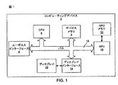
図1は、本開示で説明する技法に従ってテッセレーションを実行する例示的なコンピューティングデバイス2を示すブロック図である。コンピューティングデバイス2は、グラフィカル情報を出力する任意のワイヤードまたはワイヤレスデバイスを備えることができる。たとえば、コンピューティングデバイス2は、パーソナルコンピュータ、デスクトップコンピュータ、ラップトップコンピュータ、コンピュータワークステーション、ビデオゲームプラットフォームまたはコンソール、セルラーまたは衛星電話、インターネット電話、ポータブルビデオゲームデバイスまたは携帯情報端末(PDA)などのハンドヘルドデバイス、パーソナル音楽プレーヤ、ビデオプレーヤ、テレビジョン、あるいはグラフィカル情報を出力する別のタイプのデバイスを備えることができる。
FIG. 1 is a block diagram illustrating an
図1の例に示すように、コンピューティングデバイス2は、ユーザ入力インターフェース4と、CPU6と、デバイスメモリ8と、GPU10と、GPUメモリ12と、ディスプレイインターフェース14と、ディスプレイ16とを含む。ユーザ入力インターフェース4、CPU6、デバイスメモリ8、GPU10およびディスプレイインターフェース14は、バス18を使用して通信することができる。バス18は、第3世代バス(たとえば、HyperTransportバスまたはInfiniBandバス)、第2世代バス(たとえば、Advanced Graphics Portバス、Peripheral Component Interconnect(PCI)Expressバス、またはAdvanced eXentisible Interface(AXI)バス)、あるいは別のタイプのバスまたはデバイス相互接続など、様々なバス構造のいずれかとすることができる。
As shown in the example of FIG. 1, the
CPU6は、コンピューティングデバイス2の動作を制御する汎用または専用プロセッサを備えることができる。CPU6に1つまたは複数のソフトウェアアプリケーションを実行させるために、ユーザがコンピューティングデバイス2に入力を与えることができる。CPU6上で実行されるそれらのソフトウェアアプリケーションは、ワードプロセッサアプリケーション、スプレッドシートアプリケーション、メディアプレーヤアプリケーション、ビデオゲームアプリケーション、グラフィカルユーザインターフェースアプリケーションまたは別のエンドユーザプログラムを含むことができる。ユーザは、ユーザ入力インターフェース4を介してコンピューティングデバイス2に結合される、キーボード、マウス、マイクロフォン、タッチパッドまたは別の入力デバイスなどの、1つまたは複数の入力デバイス(図示せず)を介してコンピューティングデバイス2に入力を与えることができる。
The CPU 6 can comprise a general purpose or special purpose processor that controls the operation of the
デバイスメモリ8は、スタートアップまたはリセット時にコンピューティングデバイス2を構成するために使用できるデバイス構成情報を記憶することができる。デバイスメモリはまた、CPU6によって直ちにアクセス可能であり、および/または現在作用されているデータおよび/またはプログラムモジュールを記憶することができる。デバイスメモリ8は、GPU10によって出力された情報など、コンピューティングデバイス2の他の構成要素からの情報をさらに記憶することができる。デバイスメモリ8は、ランダムアクセスメモリ(RAM)、スタティックRAM(SRAM)、ダイナミックRAM(DRAM)、読取り専用メモリ(ROM)、消去可能プログラマブルROM(EPROM)、電気的消去可能プログラマブルROM(EEPROM)、フラッシュメモリ、磁気データ媒体または光記憶媒体など、1つまたは複数の揮発性または不揮発性のメモリまたは記憶デバイスとすることができる。
The device memory 8 can store device configuration information that can be used to configure the
GPU10は、ディスプレイ16上にコンピュータグラフィックスをレンダリングするためのグラフィックス演算を実行することに専用のものとするができる。したがって、CPU6上で実行されるソフトウェアアプリケーションの1つがグラフィックス処理を必要とするとき、CPU6は、ディスプレイ16にレンダリングするためにグラフィックス情報をGPU10に供給する。GPU10は、いくつかの例では、複雑なグラフィックス関係の演算についてCPU6よりも効率的な処理を行う並列構造を用いて構築できる。たとえば、GPU10は、完全に並列に複数の頂点ポイントに作用する複数のグラフィックスパイプラインを含むことができる。GPU10の高度並列性質により、いくつかの例では、GPU10は、CPU6を用いて複雑な2Dまたは3D画像をディスプレイ16に直接描画するよりも迅速に、それらの画像をディスプレイ16上で作成することができる。いくつかの例では、GPU10は、3Dグラフィックスをディスプレイ16にレンダリングするように設計できる。ただし、GPU10は、2D曲線のハードウェアアクセラレーテッドレンダリングを実行するために使用できる。本開示の技法は、3Dグラフィックスハードウェア、たとえば、GPU10を使用して2D曲線をレンダリングすることの効率を改善するために使用できる。 The GPU 10 can be dedicated to performing graphics operations for rendering computer graphics on the display 16. Thus, when one of the software applications running on the CPU 6 requires graphics processing, the CPU 6 supplies graphics information to the GPU 10 for rendering on the display 16. In some examples, the GPU 10 can be constructed using a parallel structure that performs more efficient processing than the CPU 6 for complex graphics-related operations. For example, GPU 10 may include multiple graphics pipelines that operate on multiple vertex points in full parallel. Due to the highly parallel nature of the GPU 10, in some instances, the GPU 10 may create those images on the display 16 more quickly than using the CPU 6 to draw complex 2D or 3D images directly on the display 16. it can. In some examples, GPU 10 can be designed to render 3D graphics on display 16. However, GPU 10 can be used to perform hardware accelerated rendering of 2D curves. The techniques of this disclosure can be used to improve the efficiency of rendering 2D curves using 3D graphics hardware, eg, GPU 10.
いくつかの例では、GPU10は、コンピューティングデバイス2のマザーボード(図示せず)に統合できる。他の例では、GPU10は、コンピューティングデバイス2のマザーボードにおけるポートに設置されるグラフィックスカード上に存在するか、または場合によってはコンピューティングデバイス2と相互運用するように構成された周辺デバイス内に組み込むことができる。GPU10は、1つまたは複数のマイクロプロセッサ、特定用途向け集積回路(ASIC)、フィールドプログラマブルゲートアレイ(FPGA)、デジタル信号プロセッサ(DSP)、あるいは他の等価な集積または個別論理回路など、1つまたは複数のプロセッサとすることができる。
In some examples, the GPU 10 can be integrated into the motherboard (not shown) of the
GPU10はGPUメモリ12に直接結合できる。したがって、GPU10は、バス18を使用することなしに、GPUメモリ12からデータを読み取り、GPUメモリ12にデータを書き込むことができる。言い換えれば、GPU10は、オフチップメモリの代わりに、ローカルストレージを使用してデータをローカルで処理することができる。これにより、GPU10は、大量のバストラフィックを受けることがある、バス18を介したデータの読取りおよび書込みの必要がなくなるので、より効率的な方法で動作できるようになる。ただし、いくつかの例では、GPU10は、別個のメモリを含まず、代わりにバス18を介してデバイスメモリ8を利用することがある。GPUメモリ12は、RAM、SRAM、DRAM、EPROM、EEPROM、フラッシュメモリ、磁気データ媒体または光記憶媒体など、1つまたは複数の揮発性または不揮発性メモリまたは記憶デバイスとすることができる。
The GPU 10 can be directly coupled to the
CPU6および/またはGPU10は、ディスプレイ16を介した提示のために、画像情報をディスプレイインターフェース14に供給することができる。複雑な2Dおよび3Dグラフィックスの場合、一般に、画像情報はディスプレイ16のためにGPU10によって発生される。ディスプレイ16は、モニタ、テレビジョン、投影デバイス、液晶ディスプレイ(LCD)、プラズマディスプレイパネル、発光ダイオード(LED)アレイ、陰極線管ディスプレイ、電子ペーパー、表面伝導型電子放出素子ディスプレイ(SED)、レーザテレビジョンディスプレイ、ナノ結晶ディスプレイまたは別のタイプのディスプレイユニットを備えることができる。ディスプレイ16はコンピューティングデバイス2内で統合できる。たとえば、ディスプレイ16は、携帯電話または他のワイヤレス通信デバイスのスクリーンとすることができる。代替的に、ディスプレイ16は、ワイヤードまたはワイヤレス通信リンクを介してコンピュータデバイス2に結合されるスタンドアロンデバイスとすることができる。たとえば、ディスプレイ16は、ケーブルまたはワイヤレスリンクを介してパーソナルコンピュータに接続されるコンピュータモニタまたはフラットパネルディスプレイとすることができる。
The CPU 6 and / or the GPU 10 can supply image information to the display interface 14 for presentation via the display 16. In the case of complex 2D and 3D graphics, generally image information is generated by the GPU 10 for the display 16. The display 16 includes a monitor, a television, a projection device, a liquid crystal display (LCD), a plasma display panel, a light emitting diode (LED) array, a cathode ray tube display, electronic paper, a surface conduction electron-emitting device display (SED), and a laser television. A display, a nanocrystal display or another type of display unit can be provided. The display 16 can be integrated within the
CPU6上で実行されるソフトウェアアプリケーションの1つが、複雑な2Dグラフィックス画像を提示することを望むとき、CPU6およびGPU10は、グラフィックスをディスプレイ16にレンダリングするように一緒に動作することができる。たとえば、ワードプロセシングアプリケーションの場合、ソフトウェアアプリケーションは、パラメトリック曲線を文書、たとえば、PDF文書にレンダリングすることを望むことがある。別の例として、ソフトウェアアプリケーションは、様々な幾何学的形状を使用して、たとえば、スケーラブルベクターグラフィックス(SVG)規格に従ってユーザインターフェースをディスプレイ16上に提示するためのソフトウェアアプリケーションとすることができる。さらなる一例では、ソフトウェアアプリケーションは、Adobe FlashおよびMicrosoft Silverlightなどのウェブアニメーションフォーマットのためにパラメトリック曲線によって2D形状をレンダリングすることを望むことがある。ソフトウェアアプリケーションは、表示すべきグラフィックス画像を形成する1つまたは複数の2D曲線を定義するコマンドを含む。たとえば、PDF文書の場合、そのアプリケーションは、様々な文字および/または数字のグラフィックス画像の曲線を定義するコマンドを含むことができる。ユーザインターフェースの場合、そのアプリケーションは、円、楕円、角丸長方形などのグラフィックス画像の曲線を定義するコマンドを含むことができる。そのコマンドは、たとえば、グラフィカル画像の境界を画定するいくつかの曲線を定義することができる。言い換えれば、そのコマンドによって定義された曲線は、文字、数字または形状の曲率を近似することができる。 When one of the software applications running on CPU 6 wants to present a complex 2D graphics image, CPU 6 and GPU 10 can work together to render the graphics on display 16. For example, for a word processing application, a software application may wish to render a parametric curve into a document, eg, a PDF document. As another example, the software application can be a software application for presenting a user interface on display 16 using various geometric shapes, for example, according to the Scalable Vector Graphics (SVG) standard. In a further example, a software application may desire to render 2D shapes with parametric curves for web animation formats such as Adobe Flash and Microsoft Silverlight. The software application includes commands that define one or more 2D curves that form a graphics image to be displayed. For example, in the case of a PDF document, the application may include commands that define curves for various character and / or numeric graphics images. In the case of a user interface, the application can include commands that define curves of graphics images such as circles, ellipses, rounded rectangles, and the like. The command can, for example, define several curves that define the boundaries of the graphical image. In other words, the curve defined by the command can approximate the curvature of letters, numbers or shapes.
一例では、ソフトウェアアプリケーションは、2005年7月28日の文献「OpenVG Specification, Version 1.0」に定義されるように、OpenVGに従って複数の経路、すなわち、曲線を定義するコマンドを含むことができる。OpenVGは、1つまたは複数のセグメントコマンドを使用して2Dのグラフィックス画像の仕様を可能にするコマンドのセットを定義する。OpenVG仕様に従って、セグメントコマンドは、直線セグメント、ベジエ曲線セグメントまたは楕円弧セグメントを定義することができる。OpenVGの拡張では、他のタイプのセグメントを指定することができる。したがって、本開示の技法は、OpenVG仕様に現在定義されているセグメントコマンドに限定されない。その上、本開示の技法についてOpenVGに関して説明するが、本技法は、SVG、Adobe Illustrator、CoreIDRAW、Adobe Flash、Microsoft Silverlight、または2Dグラフィックスを使用した他のグラフィックス演算規格など、他の2Dグラフィックスオーサリング規格に関して使用できる。 In one example, the software application may include commands that define multiple paths, or curves, according to OpenVG, as defined in the July 28, 2005 document "OpenVG Specification, Version 1.0". OpenVG defines a set of commands that allow specification of 2D graphics images using one or more segment commands. According to the OpenVG specification, the segment command can define a straight line segment, a Bezier curve segment or an elliptical arc segment. In the OpenVG extension, other types of segments can be specified. Thus, the techniques of this disclosure are not limited to segment commands currently defined in the OpenVG specification. Moreover, although the techniques of this disclosure are described with respect to OpenVG, the techniques may be used in other 2D graphics, such as SVG, Adobe Illustrator, CoreIDRAW, Adobe Flash, Microsoft Silverlight, or other graphics computing standards using 2D graphics. Can be used in relation to the authoring standard.
上記で説明したように3D画像をレンダリングするように設計できるGPU10を使用して2D曲線をディスプレイ16にレンダリングするために、CPU6は、その曲線に関連する1つまたは複数の頂点ポイントをGPU10に供給することができる。特に、CPU6は、曲線の制御ポイントを表す1つまたは複数の頂点ポイントを計算することができる。頂点ポイントの各々はいくつかの頂点の属性情報によって表すことができ、それらの頂点の属性情報は、オブジェクト空間における曲線上のその頂点ポイントのロケーションを表す位置座標(たとえば、2D曲線の場合は(x,y)座標)を含むことができる。CPU6は、たとえば、グラフィックスオーサリング仕様(たとえば、OpenVG)で指定できる、特定のコマンドセグメントに対応する数学的表現を使用して1つまたは複数の頂点ポイントを発生することができる。制御ポイントに加えて、CPU6は、レンダリングすべき曲線のタイプ、たとえば、OpenVGの場合は、直線セグメント、ベジエ曲線セグメントまたは楕円弧セグメント、および場合によっては、インデックス番号をGPU10に示すことができる。 In order to render a 2D curve on the display 16 using a GPU 10 that can be designed to render a 3D image as described above, the CPU 6 supplies the GPU 10 with one or more vertex points associated with that curve. can do. In particular, the CPU 6 can calculate one or more vertex points that represent the control points of the curve. Each vertex point can be represented by some vertex attribute information, which is the position coordinate that represents the location of that vertex point on the curve in object space (for example, ( x, y) coordinates). CPU 6 can generate one or more vertex points using a mathematical representation corresponding to a particular command segment, which can be specified, for example, in a graphics authoring specification (eg, OpenVG). In addition to the control points, the CPU 6 can indicate to the GPU 10 the type of curve to be rendered, for example, for OpenVG, a straight line segment, a Bezier curve segment or an elliptical arc segment, and possibly an index number.
CPU6は、発生された頂点ポイントを描画プリミティブのための頂点ポイントの少なくとも一部分として使用して、描画プリミティブのリストを発生することができる。CPU6は、ポイント、ラインストリップ、ラインループ、別々のライン、三角形ストリップ、三角形ファン、別々の三角形、四辺形ストリップ、別々の四辺形、または他のタイプの多角形を含むいくつかの描画プリミティブのいずれかを発生することができる。CPU6は描画プリミティブのリストをデバイスメモリ8に記憶することができる。 The CPU 6 can generate a list of drawing primitives using the generated vertex points as at least a portion of the vertex points for the drawing primitives. CPU 6 can select any of several drawing primitives including points, line strips, line loops, separate lines, triangle strips, triangle fans, separate triangles, quadrilateral strips, separate quadrilaterals, or other types of polygons. Can be generated. The CPU 6 can store a list of drawing primitives in the device memory 8.
CPU6は、一連の頂点ポイントまたは頂点ポイントの特性を定義する属性情報として描画プリミティブのリストをGPU10に通信することができる。たとえば、CPU6は、グラフィックスアプリケーションプログラミングインターフェース(API)を呼び出して、GPUドライバを介して描画プリミティブのリストをGPU10に通信することができる。グラフィックスAPIは、CPU6とGPU10との間にインターフェースを与えるソフトウェア命令のセットを備えることができる。グラフィックスAPIは、GPU10に、描画プリミティブを、表示可能なグラフィックス情報にレンダリングさせる、1つまたは複数のコマンドを作成し、発行することをGPUドライバに行わせることができる。そのコマンドは、レンダリングなど、プリミティブに対して実行すべき演算を指定することができる。さらに、そのコマンドは、プリミティブの頂点ポイントの位置座標、プリミティブの各頂点ポイントに関連するカラー情報、プリミティブの各頂点ポイントに関連するテクスチャ情報、プリミティブのためのスケーリング情報、プリミティブのための回転情報などを含むことができる。プリミティブの頂点ポイントに関連する情報は「頂点の属性情報」と呼ばれることがある。頂点の属性情報をコマンド内に含める代わりに、コマンドは、頂点の属性情報が記憶され得るデバイスメモリ8内のアドレスを指定することができる。 The CPU 6 can communicate a list of drawing primitives to the GPU 10 as attribute information defining a series of vertex points or characteristics of vertex points. For example, the CPU 6 can call a graphics application programming interface (API) to communicate a list of drawing primitives to the GPU 10 via a GPU driver. The graphics API can comprise a set of software instructions that provide an interface between the CPU 6 and the GPU 10. The graphics API can cause the GPU driver to create and issue one or more commands that cause the GPU 10 to render drawing primitives into displayable graphics information. The command can specify an operation to be performed on the primitive, such as rendering. In addition, the command includes the position coordinates of the vertex points of the primitive, color information associated with each vertex point of the primitive, texture information associated with each vertex point of the primitive, scaling information for the primitive, rotation information for the primitive, etc. Can be included. Information related to the vertex point of the primitive may be referred to as “vertex attribute information”. Instead of including vertex attribute information in the command, the command can specify an address in the device memory 8 where the vertex attribute information can be stored.
GPU10は、CPU6からコマンドを受信し、GPU10の1つまたは複数の処理要素を、コマンドにおいて指定された演算を実行するように構成する。GPU10のグラフィックスパイプラインの各々は、それぞれの頂点ポイントに対していくつかのグラフィックス演算を実行することができる。たとえば、グラフィックスパイプラインの各々は、ユーザ空間またはオブジェクト空間としても知られるモデル空間においてレンダリングすべき曲線に沿った頂点ポイントの位置座標を計算するように構成できる。GPU10は、たとえば、CPU6によって指定された曲線のタイプと制御ポイントとに関連する数式を使用してモデル空間における頂点ポイントを計算するように構成できる。別の例として、グラフィックスパイプラインの各々は、曲線、または曲線上の頂点ポイントの位置座標(または位置の属性情報)を異なる座標系に変換するように構成できる。特に、GPU10は、曲線、または曲線上の頂点ポイントの位置座標(または属性情報)をモデルまたはユーザ座標空間から(デバイス座標空間と呼ばれることがある)ディスプレイまたは表面座標空間に変換することができる。モデル座標空間は、グラフィックス処理を利用するソフトウェアアプリケーションの命令によってグラフィックス画像がどのように定義されるかを表す。一般に、入力頂点ポイントの位置座標は、浮動小数点数を使用してモデル座標空間において表すことができる。一方、ディスプレイ座標空間は、グラフィックス画像がデバイス、たとえば、ディスプレイ16上でどのように表示されるかを表すことができる。変換された頂点ポイントの位置座標は、ディスプレイ16上のピクセルロケーションに対応する整数を使用してディスプレイ座標空間において表すことができる。ただし、変換された頂点ポイントの位置座標は、浮動小数点数を使用してディスプレイ座標空間において表すことができる。 The GPU 10 receives a command from the CPU 6 and configures one or more processing elements of the GPU 10 to perform an operation specified in the command. Each of the graphics pipelines of the GPU 10 can perform several graphics operations on the respective vertex points. For example, each of the graphics pipelines can be configured to calculate the position coordinates of vertex points along a curve to be rendered in model space, also known as user space or object space. The GPU 10 can be configured to calculate vertex points in model space using, for example, mathematical formulas associated with the type of curve and control points specified by the CPU 6. As another example, each of the graphics pipelines can be configured to convert the position coordinates (or position attribute information) of a curve or vertex point on the curve to a different coordinate system. In particular, the GPU 10 can convert the position coordinates (or attribute information) of a curve, or a vertex point on the curve, from a model or user coordinate space to a display or surface coordinate space (sometimes referred to as a device coordinate space). The model coordinate space represents how a graphics image is defined by instructions of a software application that uses graphics processing. In general, the position coordinates of an input vertex point can be represented in the model coordinate space using floating point numbers. On the other hand, the display coordinate space can represent how the graphics image is displayed on a device, eg, display 16. The transformed vertex point position coordinates can be represented in the display coordinate space using an integer corresponding to the pixel location on the display 16. However, the position coordinates of the converted vertex point can be expressed in the display coordinate space using a floating point number.
いくつかの例では、モデル座標空間における2つ以上の入力頂点ポイントの位置座標は、ディスプレイ座標空間における実質的に同じ位置座標に対応することがある。したがって、GPU10は、ディスプレイ座標空間において繰返しである頂点ポイントを発生することがある。この問題は、GPU10の並列構造によって悪化することがある。言い換えれば、GPU10が完全に並列に複数の入力頂点ポイントに作用するので、ディスプレイ座標系における繰返しの頂点ポイントはグラフィックスパイプラインを介して処理されることがある。これにより、利用可能なハードウェアの使用が非効率的になり、ならびに画像がディスプレイ16にレンダリングされる速度が低減する。 In some examples, the position coordinates of two or more input vertex points in the model coordinate space may correspond to substantially the same position coordinates in the display coordinate space. Thus, the GPU 10 may generate vertex points that are repetitive in the display coordinate space. This problem may be exacerbated by the parallel structure of the GPU 10. In other words, since the GPU 10 operates on multiple input vertex points completely in parallel, repeated vertex points in the display coordinate system may be processed through the graphics pipeline. This makes the use of available hardware inefficient and reduces the speed at which images are rendered on the display 16.
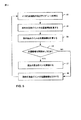
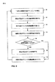
本開示の一態様によれば、GPU10は、GPU10のハードウェアリソースをより効率的に利用し、画像がディスプレイ16にレンダリングされる速度を増加させるために、1つまたは複数の頂点ポイントをグラフィックスパイプラインから除去することができる。たとえば、GPU10は、繰返しの(すなわち、冗長な)頂点ポイント、たとえば、ディスプレイ座標空間において実質的に同じ位置座標を有する頂点ポイントを除去することができる。たとえば、2つの頂点ポイントが互いから1/8ピクセル以内にある場合、すなわち、ディスプレイ座標空間におけるそれらの位置座標が0.125未満だけ異なる場合、その2つの頂点ポイントを繰返しの、すなわち冗長な、頂点ポイントと見なすことができる。グラフィックスパイプラインから冗長な頂点ポイントを除去するために、GPU10は、各頂点ポイントの位置座標の各々を前の頂点ポイントの位置座標と比較し、ディスプレイ座標空間において前の頂点ポイントと実質的に同じ位置座標を有する頂点ポイントを廃棄することができ、たとえば、位置座標間の差が0.125などのしきい値未満であるとき、頂点ポイントを廃棄することができる。このようにして、GPU10は、プリミティブをレンダリングするのに不要である冗長な情報の処理を省略することができる。 According to one aspect of the present disclosure, the GPU 10 uses one or more vertex points as a graphical spy in order to more efficiently utilize the hardware resources of the GPU 10 and increase the speed at which images are rendered on the display 16. Can be removed from the pipeline. For example, GPU 10 can remove repetitive (ie, redundant) vertex points, eg, vertex points having substantially the same position coordinates in the display coordinate space. For example, if two vertex points are within 1/8 pixel of each other, ie their position coordinates in the display coordinate space differ by less than 0.125, the two vertex points are repeated, ie redundant, It can be regarded as a vertex point. In order to remove redundant vertex points from the graphics pipeline, GPU 10 compares each of the position coordinates of each vertex point with the position coordinates of the previous vertex point and is substantially the same as the previous vertex point in the display coordinate space. Vertex points with position coordinates can be discarded, for example, when the difference between position coordinates is less than a threshold value such as 0.125. In this way, the GPU 10 can omit processing of redundant information that is unnecessary for rendering primitives.
代替または追加として、GPU10は、直線上にある、ディスプレイ座標空間における位置座標を有する選択された頂点ポイントを除去することができる。そのような状況は、3つ以上の頂点ポイントで表される曲線の部分がほとんどまたはまったく曲率を有しないときに起こる。そのような場合、曲線の部分に沿った各中間頂点ポイント間の一連の直線セグメントとしてではなく、曲線の部分の第1の頂点ポイントから曲線の部分の最後の頂点ポイントまでの直線を使用して、曲線の直線部分を等しく十分に表すことができる。言い換えれば、直線の頂点ポイントのセットのわずか2つの頂点ポイントを使用して、直線を等しく十分に確立することができる。中間または余分の頂点ポイントは除去できる。 Alternatively or in addition, the GPU 10 can remove selected vertex points with position coordinates in the display coordinate space that are on a straight line. Such a situation occurs when the portion of the curve represented by more than two vertex points has little or no curvature. In such cases, using a straight line from the first vertex point of the curve portion to the last vertex point of the curve portion, rather than as a series of straight line segments between each intermediate vertex point along the curve portion. The linear part of the curve can be represented equally well. In other words, using only two vertex points of a set of straight vertex points, a straight line can be established equally well. Intermediate or extra vertex points can be removed.
曲線の直線部分が3つの頂点ポイントを含む場合、一連の2つの直線セグメント、たとえば、第1の頂点ポイントから第2の頂点ポイントまでの第1の直線セグメント、および第2の頂点ポイントから第3の頂点ポイントまでの第2の直線セグメントとしてではなく、曲線の部分の第1の頂点ポイントから第3の頂点ポイントまでの直線を使用して、曲線の直線部分を等しく十分に表すことができる。GPU10は、たとえば、連続する頂点ポイントによって形成される第1および第2のラインセグメントの傾きを比較し、傾きが実質的に同じであるとき、たとえば、許容しきい値内であるとき、中間(第2の)頂点ポイントを除去することができる。 If the straight line portion of the curve includes three vertex points, a series of two straight line segments, eg, a first straight line segment from the first vertex point to the second vertex point, and a second vertex point to the third The straight line portion of the curve can be equally well represented using the straight line from the first vertex point to the third vertex point of the curve portion rather than as the second straight line segment to the first vertex point. The GPU 10 compares, for example, the slopes of the first and second line segments formed by successive vertex points, and when the slopes are substantially the same, for example, within the tolerance threshold, The second) vertex point can be removed.
変換された頂点ポイントを廃棄した後、GPU10は、残りの変換された頂点ポイントを使用してプリミティブを形成する。一例では、GPU10は、廃棄された頂点ポイントが決して利用できないかのように、残りの変換された頂点ポイントを使用してプリミティブを形成することができる。プリミティブを発生した後、GPU10は、画像をディスプレイ16にレンダリングするためにプリミティブに対して追加のグラフィックス演算を実行することができる。 After discarding the transformed vertex points, GPU 10 uses the remaining transformed vertex points to form a primitive. In one example, GPU 10 can use the remaining transformed vertex points to form a primitive as if the discarded vertex points were never available. After generating the primitive, the GPU 10 can perform additional graphics operations on the primitive to render the image on the display 16.
上記で説明したように、CPU6およびGPU10は、曲線をディスプレイ16にレンダリングするように互いに機能することができる。上記で説明した例では、CPU6は曲線をセグメントにテッセレーションし、GPU10は、それらのセグメントをディスプレイ16にレンダリングするためにそれらのセグメントに対して演算を実行する。しかしながら、他の例では、レンダリング機能は、CPU6とGPU10との間で別様に割り振ることができる。たとえば、GPU10は、他の演算に加えてテッセレーションを実行することができる。レンダリング機能は、CPU6の処理負荷、GPU10の処理負荷などに基づいて、CPU6とGPU10との間で割り振ることができる。 As explained above, the CPU 6 and the GPU 10 can function together to render a curve on the display 16. In the example described above, the CPU 6 tessellates the curves into segments and the GPU 10 performs operations on those segments to render those segments on the display 16. However, in other examples, rendering functions can be allocated differently between the CPU 6 and the GPU 10. For example, the GPU 10 can perform tessellation in addition to other operations. The rendering function can be allocated between the CPU 6 and the GPU 10 based on the processing load of the CPU 6, the processing load of the GPU 10, and the like.
さらに、コンピューティングデバイス2はいくつかの他の要素を含むことができる。たとえば、コンピューティングデバイス2は、符号化ビデオの送信および受信のために適切な変調、復調、周波数変換、フィルタ処理、および増幅器構成要素を含み、適用可能な場合、ワイヤレス通信をサポートするのに十分な無線周波(RF)ワイヤレス構成要素およびアンテナを含むことができる。したがって、コンピューティングデバイス2はハンドヘルドワイヤレス通信デバイスを備えることができる。ただし、説明を簡単にするために、これらの追加の要素は、図1には特に示していない。むしろ、図1に示すアーキテクチャは例にすぎない。本開示で説明する技法は、様々な他のアーキテクチャを用いて実装できる。
Further, the
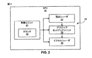
図2は、図1のGPU10をさらに詳細に示すブロック図である。GPU10は、制御ユニット21と、頂点シェーダ22と、プリミティブセットアップユニット24と、ピクセルシェーダ26とを含むグラフィックスパイプライン20を含む。上記で説明したように、GPU10は、複雑なグラフィックス関係の演算のより効率的な処理を行う高度並列構造を有することができる。したがって、図2にはただ1つのグラフィックスパイプライン20が示されているが、GPU10は、頂点ポイントの複数のセット(たとえば、プリミティブ)に並列に作用する複数の同様のグラフィックスパイプラインを含むことができる。言い換えれば、GPU10は、完全に並列にいくつかのデータプリミティブに作用することができる、複数の頂点シェーダ22と、プリミティブセットアップユニット24と、ピクセルシェーダ26とを含むことができる。GPU10の高度並列性質により、いくつかの例では、GPU10は、CPU6を用いて複雑な2Dまたは3Dグラフィックス画像をディスプレイ16に直接描画するよりも迅速に、それらの画像をディスプレイ16上で作成することができる。一例では、GPU10は、3Dグラフィックスをレンダリングするように設計できる。
FIG. 2 is a block diagram showing the GPU 10 of FIG. 1 in more detail. The GPU 10 includes a
GPU10は、2Dまたは3Dグラフィック画像を表示のためにレンダリングするようにCPU6とともに動作することができる。GPU10の制御ユニット21は、プリミティブを定義する1つまたは複数の頂点ポイントに対して演算を実行するようにGPU10に命令するコマンドをCPU6から受信する。制御ユニット21は、そのコマンドを復号し、GPU10の1つまたは複数の処理要素を、そのコマンドにおいて指定された演算を実行するように構成する。制御ユニット21は、さらに、コマンド内に含まれる情報(たとえば、プリミティブまたは頂点の情報)をGPUメモリ12(図1)に、またはGPU10内の1つまたは複数のバッファ(図示せず)内に、またはGPU10の処理要素内に、記憶することができる。制御ユニット21は、GPU10の処理要素に特定のグラフィックス処理演算を実行させる命令のセットを、GPU10の処理要素の各々にロードすることができる。図2に示す例では、GPU10の処理要素には、頂点シェーダ22、プリミティブセットアップユニット24、およびピクセルシェーダ26がある。他の処理要素をGPU10中に含めることもできるが、説明を簡単で容易にするために図2には特に示していない。
The GPU 10 can operate with the CPU 6 to render 2D or 3D graphic images for display. The
頂点シェーダ22、プリミティブセットアップユニット24、およびピクセルシェーダ26は、パイプラインとして動作することができる。パイプラインとして動作するとき、頂点シェーダ22は、入力データの第1のセットに対して1つまたは複数のグラフィックス演算の第1のセットを実行し、中間結果の第1のセットを出力する。プリミティブセットアップユニット24は、頂点シェーダ22によって出力された中間結果に対して1つまたは複数のグラフィックス演算の第2のセットを実行し、中間結果の第2のセットを出力する。初期入力データの第2のセットに対して、頂点シェーダ22はグラフィックス演算の第1のセットを実行し、プリミティブセットアップユニット24はグラフィックス演算の第2のセットを実行する。表示のためにグラフィックス画像が発生されるまで、グラフィックス処理は同様の方法で続く。 Vertex shader 22, primitive setup unit 24, and pixel shader 26 may operate as a pipeline. When operating as a pipeline, the vertex shader 22 performs a first set of one or more graphics operations on the first set of input data and outputs a first set of intermediate results. The primitive setup unit 24 performs a second set of one or more graphics operations on the intermediate results output by the vertex shader 22 and outputs a second set of intermediate results. For the second set of initial input data, the vertex shader 22 performs a first set of graphics operations and the primitive setup unit 24 performs a second set of graphics operations. Graphics processing continues in a similar manner until a graphics image is generated for display.
頂点シェーダ22は、CPU6によって発生された1つまたは複数の頂点ポイントを定義する頂点の属性情報のシーケンスを得るように構成できる。頂点シェーダ22は、頂点の属性情報のシーケンスをデバイスメモリ8(図1)から取り出すことができる。CPU6から受信したコマンドは、頂点の属性情報が記憶されたデバイスメモリ8内のロケーションを示すことができる。代替的に、CPU6は、頂点の属性情報をそのコマンド内に、または1つまたは複数の後続のコマンドに含めることができる。 Vertex shader 22 can be configured to obtain a sequence of vertex attribute information that defines one or more vertex points generated by CPU 6. The vertex shader 22 can take out a sequence of vertex attribute information from the device memory 8 (FIG. 1). The command received from the CPU 6 can indicate the location in the device memory 8 where the vertex attribute information is stored. Alternatively, the CPU 6 can include vertex attribute information in the command or in one or more subsequent commands.
頂点の属性情報は、位置の属性情報、1つまたは複数のカラー属性情報、1つまたは複数のテクスチャ属性情報、1つまたは複数のライティング属性情報、1つまたは複数の透明度の属性情報などを含むことができる。位置の属性情報は、頂点ポイントのシーケンスにおける現在の頂点ポイントの順序位置を示すインデックス番号とすることができる。たとえば、曲線がN個の頂点ポイントを有するとき、インデックス番号は0からNまでの整数を備える。代替的に、頂点ポイントの位置の属性情報は、モデル空間における曲線上にあるポイントのロケーションを表す位置座標、たとえば、2Dの場合は(xo,yo)座標とすることができる。頂点ポイントの位置の属性情報は、たとえば、グラフィックスオーサリング仕様(たとえば、OpenVG)で指定できる、特定のコマンドセグメントに対応する数学的表現を使用してCPU6によって計算できる。たとえば、OpenVGを使用して楕円弧曲線として定義される曲線の場合、次式を使用して頂点ポイントの位置の属性情報を計算することができる。

上式で、(xo,yo)はモデル空間における曲線上の頂点ポイントの位置座標であり、aは楕円の半長軸であり、bは楕円の半短軸であり、0≦θ≦2πである。式(1)および式(2)とともに、CPU6は、変数a、b、およびθをGPU10に送信することができる。上記で説明したように、モデル座標空間は、一般に浮動小数点数を使用して、グラフィックス処理を利用するソフトウェアアプリケーションの命令によってグラフィックス画像がどのように定義されるかを表す。 Where (x o , y o ) is the position coordinate of the vertex point on the curve in model space, a is the half major axis of the ellipse, b is the half minor axis of the ellipse, and 0 ≦ θ ≦ 2π. Along with Expression (1) and Expression (2), the CPU 6 can transmit variables a, b, and θ to the GPU 10. As explained above, the model coordinate space typically uses floating point numbers to represent how a graphics image is defined by the instructions of a software application that utilizes graphics processing.
位置の属性情報に基づいて、頂点シェーダ22はディスプレイ座標空間における位置座標を判断する。(ユーザまたはデバイス座標空間と呼ばれることがある)ディスプレイ座標空間は、グラフィックス画像がデバイス、たとえば、ディスプレイ上でどのように表示されるかを表す。ディスプレイ16は整数個の物理ピクセルのアレイからなるので、デバイス座標空間における位置座標(x,y)は、ディスプレイ16上のピクセルロケーションにマッピングする。頂点シェーダ22は、以下でさらに詳細に説明するように、グラフィカルソフトウェアアプリケーションによって定義された曲線を表す同じ数式を使用して、ただしディスプレイ座標空間に変換される変数(または制御ポイント)を用いて、頂点ポイントの位置座標を計算することができる。 Based on the position attribute information, the vertex shader 22 determines position coordinates in the display coordinate space. A display coordinate space (sometimes referred to as a user or device coordinate space) represents how a graphics image is displayed on a device, eg, a display. Since the display 16 consists of an array of an integer number of physical pixels, the position coordinates (x, y) in the device coordinate space map to pixel locations on the display 16. The vertex shader 22 uses the same formulas representing the curves defined by the graphical software application, but uses variables (or control points) that are converted to the display coordinate space, as described in more detail below. The position coordinates of the vertex point can be calculated.
頂点シェーダ22は、他の入力頂点の属性情報に対していくつかの他の演算を実行することができる。頂点シェーダ22は、頂点ポイントのカラー属性情報、テクスチャ属性情報、ライティング属性情報、または透明度の属性情報のうちの1つまたは複数を変更するために、1つまたは複数の演算を実行することができる。簡単のために、本開示では、頂点ポイントの位置座標の変換のみについて説明する。ただし、頂点シェーダ22は他の頂点の属性情報に対して他の演算を実行することができることを理解されたい。 Vertex shader 22 can perform some other operations on the attribute information of other input vertices. Vertex shader 22 may perform one or more operations to change one or more of vertex point color attribute information, texture attribute information, lighting attribute information, or transparency attribute information. . For simplicity, this disclosure describes only the transformation of the vertex point position coordinates. However, it should be understood that the vertex shader 22 can perform other operations on the attribute information of other vertices.
GPU10のハードウェアリソースをより効率的に利用し、画像がディスプレイ16にレンダリングされる速度を増加させるために、頂点シェーダ22は1つまたは複数の頂点ポイントを除去することができる。頂点シェーダ22は、たとえば、空間的繰返しの(すなわち、冗長な)頂点ポイントを除去するか、直線上にある余分の頂点ポイントを除去するか、または両方を行うことができる。 In order to more efficiently utilize the hardware resources of the GPU 10 and increase the speed at which images are rendered on the display 16, the vertex shader 22 can remove one or more vertex points. Vertex shader 22 may, for example, remove spatially repeating (ie, redundant) vertex points, remove extra vertex points that are on a straight line, or both.
ディスプレイ座標空間における位置座標はピクセルロケーションの整数に対応するので、2つ以上の頂点ポイントが、いくつかの例では、同じピクセルロケーションにマッピングすることがある。言い換えれば、2つ以上の頂点ポイントが、ディスプレイ座標空間において実質的に同じ位置座標を有することがある。たとえば、モデル座標空間における、または2つの連続するインデックス番号で表される、2つ以上の頂点ポイントは、頂点シェーダ22によって変換されると、ディスプレイ座標空間における実質的に同じ位置座標に対応することがある。したがって、GPU10は、特定のピクセルロケーションと対応する2つ以上の頂点ポイントを発生することがある。このようにして、GPU10はディスプレイ座標空間において繰返しの頂点ポイントを発生することがある。ディスプレイ座標空間における頂点ポイントは、プリミティブをレンダリングするのに不要である冗長な情報と見なすことができる。 Since position coordinates in the display coordinate space correspond to an integer number of pixel locations, more than one vertex point may map to the same pixel location in some examples. In other words, two or more vertex points may have substantially the same position coordinates in the display coordinate space. For example, two or more vertex points in the model coordinate space or represented by two consecutive index numbers, when transformed by the vertex shader 22, correspond to substantially the same position coordinates in the display coordinate space. There is. Thus, the GPU 10 may generate more than one vertex point corresponding to a particular pixel location. In this way, the GPU 10 may generate repeated vertex points in the display coordinate space. Vertex points in the display coordinate space can be viewed as redundant information that is not necessary to render the primitive.
GPU10の並列構造により、GPU10の処理要素は、プリミティブをレンダリングする際に必要とされる頂点ポイントと並列に、プリミティブをレンダリングするのに不要である頂点ポイントに作用することがある。たとえば、GPU10は、直線上にある繰返しの頂点ポイントまたは余分の頂点ポイントに作用することがあり、それにより、利用可能なハードウェアの使用が非効率的になり、ならびに画像がディスプレイ16にレンダリングされる速度が低減する。繰返しの、または場合によっては余分の頂点ポイントに作用する代わりに、GPU10が、繰返しの頂点ポイント、たとえば、ディスプレイ座標空間における実質的に同じ位置座標に対応する頂点ポイントを廃棄すればより効率的となり、それによって、GPU10は、非繰返しの頂点ポイントに作用するためのGPU10のハードウェアリソースを利用することができるようになる。 Due to the parallel structure of the GPU 10, the processing elements of the GPU 10 may operate on vertex points that are unnecessary to render the primitive in parallel with the vertex points required when rendering the primitive. For example, the GPU 10 may act on repeated or extra vertex points that are on a straight line, thereby making the use of available hardware inefficient, as well as rendering an image on the display 16. Speed is reduced. Instead of acting on repetitive or possibly extra vertex points, it becomes more efficient if GPU 10 discards repetitive vertex points, eg, vertex points corresponding to substantially the same position coordinates in the display coordinate space. This allows the GPU 10 to utilize the hardware resources of the GPU 10 for acting on non-repeating vertex points.
この目的で、頂点シェーダ22は、本開示の一態様によれば、1つまたは複数の頂点ポイントを除去することができる。一例では、頂点シェーダ22は、GPU10のハードウェアリソースをより効率的に利用し、画像がディスプレイ16にレンダリングされる速度を増加させるために、たとえば、ディスプレイ座標空間において同じまたは実質的に同じ位置座標を有する、冗長である頂点ポイントをグラフィックスパイプラインから除去することができる。一態様では、頂点シェーダ22は、現在の頂点ポイントについての位置座標、ならびに少なくとも1つの前の頂点ポイントについての位置座標を計算することができる。頂点シェーダ22は、現在のおよび前の頂点ポイントの位置座標(すなわち、ディスプレイ座標空間における位置座標)を比較し、現在のおよび前の頂点ポイントの位置座標が実質的に同じであるとき、現在の頂点ポイントを廃棄する。現在の頂点ポイントが頂点シェーダ22によって廃棄されたとき、頂点シェーダ22は、いかなる出力をも与えないことがある。代替的に、頂点シェーダ22は、現在の頂点ポイントが廃棄されたことを示す信号を出力することがある。その信号により、パイプラインの次の処理段は、その処理段が頂点ポイントを受信しないことを知ることができ得、リソースは他の演算のために解放できる。 For this purpose, the vertex shader 22 can remove one or more vertex points according to one aspect of the present disclosure. In one example, the vertex shader 22 utilizes the hardware resources of the GPU 10 more efficiently and increases the speed at which images are rendered on the display 16, for example, the same or substantially the same position coordinates in the display coordinate space. Vertex points that have redundancy can be removed from the graphics pipeline. In one aspect, vertex shader 22 can calculate position coordinates for the current vertex point as well as position coordinates for at least one previous vertex point. Vertex shader 22 compares the position coordinates of the current and previous vertex points (ie, the position coordinates in the display coordinate space), and when the position coordinates of the current and previous vertex points are substantially the same, Discard vertex points. When the current vertex point is discarded by the vertex shader 22, the vertex shader 22 may not give any output. Alternatively, vertex shader 22 may output a signal indicating that the current vertex point has been discarded. With that signal, the next processing stage in the pipeline can know that the processing stage does not receive a vertex point, and resources can be released for other operations.
ディスプレイ座標空間における現在のおよび前の頂点ポイントの位置座標が実質的に同じでないとき、頂点シェーダ22は、現在の頂点ポイントの、ディスプレイ座標空間における位置座標を含む、頂点の属性情報を出力する。この場合、少なくとも1つの前の頂点ポイントの位置座標は、現在の頂点ポイントが冗長であるかどうかを判断するために使用される。GPU10は、すべてのN+1個の頂点に対して同様のプロセスを並列に実行することができる。 When the position coordinates of the current and previous vertex points in the display coordinate space are not substantially the same, the vertex shader 22 outputs vertex attribute information including the position coordinates of the current vertex point in the display coordinate space. In this case, the position coordinates of the at least one previous vertex point are used to determine whether the current vertex point is redundant. The GPU 10 can perform the same process in parallel for all N + 1 vertices.
頂点シェーダ22を構成する際に、制御ユニット21は、頂点シェーダ22に上記で説明した機能を実行させる命令のセットを頂点シェーダ22にロードすることができる。以下でさらに詳細に説明するように、モデル空間および/またはディスプレイ座標空間において曲線の位置座標を計算するための数式、ならびにその位置座標を計算する際に必要な任意の変数を定義する、命令を頂点シェーダ22にロードすることができる。以下は、頂点シェーダ22にロードでき、繰返しの頂点ポイントを除去するために使用できる例示的な擬似コードである。
上記の例示的な擬似コードでは、頂点シェーダ22は、インデックスまたはシーケンス番号を表す位置の属性情報(index)を使用して現在のおよび前の頂点ポイントの位置座標を頂点シェーダ22に得させる命令とともに構成される。その例示的な擬似コードでは、頂点シェーダ22は、開始角が0である1ラジアンの円弧についての位置座標を計算するように構成される。特に、頂点シェーダ22は、円弧の半径、最大インデックス値N、グラフィカルソフトウェアアプリケーションによって定義された曲線についてのモデル空間におけるxおよびyの位置座標を定義する数式、すなわち、それぞれ、x=radius*cos(t)およびy=radius*sin(t)とともに構成される。 In the exemplary pseudo code above, the vertex shader 22 uses instructions to cause the vertex shader 22 to obtain the position coordinates of the current and previous vertex points using position attribute information (index) representing an index or sequence number. Composed. In the exemplary pseudo code, the vertex shader 22 is configured to calculate the position coordinates for a 1 radian arc with a starting angle of zero. In particular, the vertex shader 22 is an equation that defines the x and y position coordinates in the model space for the radius of the arc, the maximum index value N, and the curve defined by the graphical software application, i.e., x = radius * cos (respectively). t) and y = radius * sin (t).
頂点シェーダ22は、位置の属性情報(index)および最大インデックス値(N)に基づいて浮動小数点値tを計算する。頂点シェーダ22はまた、変数tのステップサイズ(delta)を1/Nであるものとして計算し、それは均一なステップサイズを表す。他の例では、ステップサイズは、曲線の曲率に基づいて適応するものとすることができる。計算された浮動小数点値tを使用して、頂点シェーダ22は、ディスプレイ座標空間におけるx軸位置座標(x_curr)とディスプレイ座標空間におけるy軸位置座標(y_curr)とを計算する。特に、頂点シェーダ22は、x_currをradius*cos(t)の整数値として計算し、ただし、tはindex/Nの浮動小数点値に等しい。言い換えれば、頂点シェーダ22は、式radius*cos(t)によって出力された値を最も近い整数値に丸める。同様に、頂点シェーダ22は、式radius*sin(t)によって出力された値を最も近い整数値に丸めることによってy_currを計算する。このようにして、頂点シェーダ22は、モデル座標空間における位置座標を最も近い整数値に丸めることによって、モデル座標空間における位置座標をディスプレイ座標空間における位置座標に変換する。 The vertex shader 22 calculates a floating point value t based on the position attribute information (index) and the maximum index value (N). Vertex shader 22 also calculates the step size (delta) of variable t as being 1 / N, which represents a uniform step size. In other examples, the step size may be adapted based on the curvature of the curve. Using the calculated floating point value t, the vertex shader 22 calculates the x-axis position coordinate (x_curr) in the display coordinate space and the y-axis position coordinate (y_curr) in the display coordinate space. In particular, vertex shader 22 calculates x_curr as an integer value of radius * cos (t), where t is equal to a floating point value of index / N. In other words, the vertex shader 22 rounds the value output by the expression radius * cos (t) to the nearest integer value. Similarly, the vertex shader 22 calculates y_curr by rounding the value output by the expression radius * sin (t) to the nearest integer value. In this way, the vertex shader 22 converts the position coordinate in the model coordinate space to the position coordinate in the display coordinate space by rounding the position coordinate in the model coordinate space to the nearest integer value.
さらに、頂点シェーダ22は、前の頂点ポイントについてディスプレイ座標空間における位置座標(x_prev,y_prev)を同様に計算することができる。特に、頂点シェーダ22は、式radius*cos(t−delta)によって出力された値を最も近い整数値に丸めることによってx_prevを計算し、式radius*sin(t−delta)によって出力された値を最も近い整数値に丸めることによってy_prevを計算する。上記の例示的な擬似コードでは、頂点シェーダ22が、モデル座標空間における位置座標を最も近い整数値に丸めることによってモデル座標空間における位置座標をディスプレイ座標空間における位置座標に変換するが、頂点シェーダ22は、ディスプレイ座標空間における位置座標を浮動小数点数として保持することができる。さらに、頂点シェーダ22は、変換プロセス中に、スケーリング、回転など、他の変換演算を実行することができる。この場合、浮動小数点値を最も近い整数値に丸めることに加えて、他の数学演算が実行できる。 Further, the vertex shader 22 can similarly calculate the position coordinates (x_prev, y_prev) in the display coordinate space for the previous vertex point. In particular, the vertex shader 22 calculates x_prev by rounding the value output by the expression radius * cos (t-delta) to the nearest integer value, and the value output by the expression radius * sin (t-delta) is calculated. Calculate y_prev by rounding to the nearest integer value. In the above exemplary pseudo code, the vertex shader 22 converts the position coordinate in the model coordinate space to the position coordinate in the display coordinate space by rounding the position coordinate in the model coordinate space to the nearest integer value. Can hold the position coordinates in the display coordinate space as a floating point number. Furthermore, the vertex shader 22 can perform other conversion operations such as scaling and rotation during the conversion process. In this case, in addition to rounding the floating point value to the nearest integer value, other mathematical operations can be performed.
頂点シェーダ22は、現在の頂点ポイントの計算された位置座標を前の頂点ポイントの計算された位置座標と比較し、位置座標がディスプレイ座標系において同じであるとき、現在の頂点ポイントを廃棄する。言い換えれば、頂点シェーダ22は、両方のx軸位置座標が同じであり(x_curr=x_prev)、両方のy軸位置座標が同じである(y_curr=y_prev)とき、現在の頂点ポイントを廃棄する。gl_Position.xは、頂点のx座標の位置に等しい値をとる浮動小数点値であり、gl_Position.yは、頂点のy座標の位置に等しい値をとる浮動小数点値である。gl_Position.xおよびgl_Position.yにより、頂点シェーダ22は、その頂点位置が配置される固有のレジスタを指定することができる。ディスプレイ座標空間における位置座標が浮動小数点数として表される場合は、2つの頂点ポイントの値の差が、互いから1/8ピクセル以内であるとき、すなわち、ディスプレイ座標空間における2つの頂点ポイントの位置座標が、両方の次元(たとえば、x次元とy次元)で0.125未満だけ異なるとき、現在の頂点ポイントを廃棄する。上記ではディスプレイ座標空間において行われるものとして説明したが、頂点シェーダ22は、モデルまたはユーザ座標空間においてその比較を実行することによって頂点ポイントを廃棄することができる。 Vertex shader 22 compares the calculated position coordinates of the current vertex point with the calculated position coordinates of the previous vertex point, and discards the current vertex point when the position coordinates are the same in the display coordinate system. In other words, the vertex shader 22 discards the current vertex point when both x-axis position coordinates are the same (x_curr = x_prev) and both y-axis position coordinates are the same (y_curr = y_prev). gl_Position. x is a floating point value having a value equal to the position of the x coordinate of the vertex, and gl_Position. y is a floating point value that takes a value equal to the position of the y coordinate of the vertex. gl_Position. x and gl_Position. With y, the vertex shader 22 can specify a unique register in which the vertex position is placed. When the position coordinate in the display coordinate space is expressed as a floating point number, when the difference between the values of the two vertex points is within 1/8 pixel from each other, that is, the position of the two vertex points in the display coordinate space When the coordinates differ in both dimensions (eg, x and y dimensions) by less than 0.125, the current vertex point is discarded. Although described above as being performed in the display coordinate space, the vertex shader 22 can discard the vertex points by performing the comparison in the model or user coordinate space.
上記の例では、頂点シェーダ22は、頂点位置の属性情報として現在の頂点ポイントのインデックス値を入力する。そのインデックス値は0からNまでの整数値をとることができ、各後続の頂点ポイントはシーケンスの次のインデックス値を有する。言い換えれば、現在の頂点ポイントのインデックス値が「2」である場合、前の頂点ポイントのインデックス値は「1」であり、後続の頂点ポイントのインデックス値は「3」であり、以下同様である。本開示の技法の一態様では、GPU10は、この属性情報をデバイスメモリ8から読み取る代わりに、またはその属性情報を含むコマンドをCPU6から受信する代わりに、整数のこのシーケンスを発生することができる。GPU10内で整数のシーケンスを発生することにより、バス18上で使用される帯域幅の量を低減することができる。
In the above example, the vertex shader 22 inputs the index value of the current vertex point as the vertex position attribute information. Its index value can take an integer value from 0 to N, with each subsequent vertex point having the next index value in the sequence. In other words, if the index value of the current vertex point is “2”, the index value of the previous vertex point is “1”, the index value of the subsequent vertex point is “3”, and so on. . In one aspect of the techniques of this disclosure, the GPU 10 can generate this sequence of integers instead of reading this attribute information from the device memory 8 or receiving a command containing that attribute information from the CPU 6. By generating an integer sequence within the GPU 10, the amount of bandwidth used on the
制御ユニット21は、たとえば、0からNまでの処理された頂点ポイントをカウントするために使用されるカウンタ28を維持することができる。したがって、頂点ポイントの頂点の属性情報が頂点シェーダ22にロードされたとき、制御ユニット21は一般にカウンタ28を増分する。いくつかの態様では、制御ユニット21は、カウンタ28をインデックス属性情報のソースとして使用することができる。たとえば、制御ユニット21は、カウンタ28の値を現在の頂点ポイントについてのインデックス属性情報として与え、現在のインデックス値を頂点シェーダ22にロードしたときに、カウンタ28の値を1だけ増分することができる。これにより、デバイスメモリ8またはCPU6から位置頂点の属性情報をロードする必要がなくなるので、バス18上での着信帯域幅消費の量が減少する。
The
頂点シェーダ22は、いくつかの例では、実質的直線上にある余分の頂点ポイントを除去することによって、CPU6から受信した頂点ポイントのセットから頂点ポイントの数を低減することができる。言い換えれば、頂点シェーダ22は、前の頂点ポイントおよび後続の頂点ポイントを使用して確立される直線上に実質的にある中間頂点ポイントを除去することができる。本開示で説明するように、直線上にある中間または余分の頂点ポイントは、プリミティブをレンダリングするのに不要であることがある。頂点シェーダ22は、冗長な頂点ポイントを除去することなしに、または冗長な頂点ポイントを除去することに加えて、実質的直線上にある余分のまたは中間頂点ポイントを除去することができる。 Vertex shader 22 may reduce the number of vertex points from the set of vertex points received from CPU 6 by removing extra vertex points that are substantially on a straight line in some examples. In other words, the vertex shader 22 can remove intermediate vertex points that are substantially on a straight line established using the previous and subsequent vertex points. As described in this disclosure, intermediate or extra vertex points that lie on a straight line may be unnecessary to render a primitive. Vertex shader 22 can remove extra or intermediate vertex points that lie on a substantially straight line without removing redundant vertex points or in addition to removing redundant vertex points.
直線上の余分のまたは中間頂点ポイントを除去するために、頂点シェーダ22は、3つの頂点ポイントをもつ直線セグメントの場合、現在の頂点ポイントについて、ならびに前の頂点ポイントおよび後続の頂点ポイントについて、ディスプレイ座標空間における位置座標を計算することができる。同様の技法は、4つ以上の頂点ポイントをもつ直線セグメントで使用できる。頂点シェーダ22は、上記で詳細に説明したように、それらの頂点ポイントの位置座標を同様に計算することができる。一例として、頂点シェーダ22は、上記の例示的な擬似コードにおいて説明したように、ディスプレイ座標空間における、現在の頂点ポイントについての位置座標(x_curr,y_curr)および前の頂点ポイントについての位置座標(x_prev,y_prev)を計算し、さらに、t=t+deltaを使用して後続の頂点ポイントの変換された位置座標(x_subs,y_subs)を計算することができる。 To remove extra or intermediate vertex points on a straight line, the vertex shader 22 displays for the current vertex point and for the previous and subsequent vertex points for a straight line segment with three vertex points. The position coordinates in the coordinate space can be calculated. Similar techniques can be used with straight line segments having more than three vertex points. The vertex shader 22 can similarly calculate the position coordinates of those vertex points as described in detail above. As an example, the vertex shader 22 may be the position coordinate (x_curr, y_curr) for the current vertex point and the position coordinate (x_prev) for the previous vertex point in the display coordinate space, as described in the example pseudo code above. , Y_prev) and t = t + delta can be used to calculate the transformed position coordinates (x_subs, y_subs) of subsequent vertex points.
前の頂点ポイント、現在の頂点ポイントおよび後続の頂点ポイントについて変換された位置頂点ポイントを計算した後、頂点シェーダ22は、それらの変換された位置頂点ポイントが実質的直線上にあるかどうかを判断する。そうするために、頂点シェーダ22は、現在の頂点ポイントと前の頂点ポイントとの位置座標を接続するラインセグメントの傾きを、後続の頂点ポイントと現在の頂点ポイントとの位置座標を接続するラインセグメントの傾きと比較することができる。両方のラインセグメントの傾きが実質的に等しい(たとえば、許容差、または以下の式(3)中の「THR」以内である)とき、頂点シェーダ22は、それらの頂点ポイントが実質的直線上にあると判断する。頂点シェーダ22は、たとえば、次式が満たされたとき、変換された位置頂点ポイントが直線上にあると判断することができる。
頂点シェーダ22は、頂点ポイントの変換された位置座標が実質的直線上にある(すなわち、THR以下である)と判断したとき、現在の頂点ポイントを廃棄する。いくつかの例では、頂点シェーダ22は、頂点ポイントが直線上にあるかどうかを判断する際に、特定の程度の誤りを許容することができる。 When the vertex shader 22 determines that the transformed position coordinates of the vertex point are on a substantially straight line (ie, less than or equal to THR), it discards the current vertex point. In some examples, vertex shader 22 can tolerate a certain degree of error in determining whether a vertex point is on a straight line.
いくつかの例では、GPU10は、曲線の高次導関数を計算し、頂点ポイントを廃棄すべきかどうかを判断する際にその高次導関数を使用することができる。たとえば、GPU10は、曲線の曲率(たとえば、傾き)を表す2次導関数を計算し、頂点ポイントのロケーションにおける曲線の曲率に基づいて、頂点ポイントを廃棄すべきかどうかを判断することができる。たとえば、曲線の曲率が頂点ポイントのロケーションにおいて高い値を有する場合、GPU10は、その頂点ポイントを廃棄しないことを判断することができる。 In some examples, the GPU 10 can calculate a higher order derivative of the curve and use that higher order derivative in determining whether the vertex point should be discarded. For example, the GPU 10 can calculate a second derivative representing the curvature (eg, slope) of the curve and determine whether to discard the vertex point based on the curvature of the curve at the location of the vertex point. For example, if the curvature of the curve has a high value at the location of the vertex point, the GPU 10 can determine not to discard the vertex point.
頂点シェーダ22が、現在の頂点ポイントを保持することを判断したとき、たとえば、その頂点ポイントが、重複または冗長な頂点ポイントでないか、あるいは隣接頂点ポイントをもつ直線上にないとき、頂点シェーダ22は、変換された頂点ポイント、また変換された頂点ポイントを定義する属性情報を出力する。一例では、頂点シェーダ22は、その出力された頂点ポイント、または変換された頂点ポイントを定義する属性情報を、グラフィックスパイプライン20における次の段、たとえば、プリミティブセットアップユニット24に直接供給することができる。他の例では、頂点シェーダ22は、変換された頂点ポイント、または変換された頂点ポイントを定義する属性情報をGPUメモリ12またはデバイスメモリ8などのメモリに記憶することができる。
When the vertex shader 22 determines to keep the current vertex point, for example, when the vertex point is not an overlapping or redundant vertex point or is not on a straight line with an adjacent vertex point, the vertex shader 22 The converted vertex point and attribute information defining the converted vertex point are output. In one example, vertex shader 22 may provide attribute information defining its output vertex points or transformed vertex points directly to the next stage in
上記で説明した例では、頂点シェーダ22は、前のおよび/または後続の頂点ポイントを使用して、現在の頂点ポイントに関する判断を行う。言い換えれば、頂点シェーダ22は、前のおよび/または後続の頂点ポイントの位置座標を計算して、頂点が、前の頂点ポイントの重複であるかどうか、または前の頂点ポイントおよび後続の頂点ポイントをもつ直線上にあるかどうかを判断する。したがって、曲線上の各頂点ポイントについて、頂点シェーダ22は、現在の頂点ポイントを変換するために、2つ以上の追加の「オーバーヘッド」計算を実行する。たとえば、現在の頂点ポイントの位置座標が前の頂点ポイントの位置座標と実質的に同じであるかどうかを判断するために、頂点シェーダ22は、現在の頂点ポイントの位置座標を変換することに加えて、前の頂点ポイントの位置座標を変換する。このことは、実行されたであろう唯一の演算が現在の頂点ポイントの位置座標を変換することであると仮定すると、オーバーヘッド計算の100%の増加(たとえば、実行される演算の数の100%の増加)をもたらすことがある。別の例として、現在の頂点ポイントの位置座標が、前のおよび後続の頂点ポイントをもつ直線上にあるかどうかを判断するために、頂点シェーダ22は、前の頂点ポイントと、現在の頂点ポイントと、後続の頂点ポイントとの位置座標を変換する。このことは、実行されたであろう唯一の演算が現在の頂点ポイントの位置座標を変換することであると仮定すると、オーバーヘッド計算の200%の増加をもたらすことがある。しかしながら、これらのオーバーヘッド計算は、グラフィックスパイプライン20において後で実行されるいくつかの他のより複雑な計算をなくすことができる。
In the example described above, vertex shader 22 uses the previous and / or subsequent vertex points to make a determination regarding the current vertex point. In other words, the vertex shader 22 calculates the position coordinates of the previous and / or subsequent vertex points to determine whether the vertex is an overlap of the previous vertex point or whether the previous and subsequent vertex points are Judge whether it is on the straight line with. Thus, for each vertex point on the curve, vertex shader 22 performs two or more additional “overhead” calculations to transform the current vertex point. For example, in order to determine whether the position coordinates of the current vertex point are substantially the same as the position coordinates of the previous vertex point, the vertex shader 22 in addition to transforming the position coordinates of the current vertex point To convert the position coordinates of the previous vertex point. This assumes a 100% increase in overhead computation (eg, 100% of the number of operations performed), assuming that the only operation that would have been performed is to transform the position coordinates of the current vertex point. Increase). As another example, in order to determine whether the position coordinates of the current vertex point are on a straight line with previous and subsequent vertex points, the vertex shader 22 determines whether the previous vertex point and the current vertex point are And the position coordinates of the subsequent vertex point are converted. This can lead to a 200% increase in overhead calculations, assuming that the only operation that would have been performed is to transform the position coordinates of the current vertex point. However, these overhead calculations can eliminate some other more complex calculations performed later in the
いくつかの例では、頂点シェーダ22は、複数の頂点ポイントを変換することによって、このオーバーヘッド計算を低減するように構成できる。一例として、頂点シェーダ22は、4つの頂点ポイントを同時に変換するように構成できる。この例では、頂点シェーダ22は、インデックス値(i)を得て、5つの頂点ポイント、たとえば、インデックス値i−1、i、i+1、i+2、およびi+3に対応する頂点ポイントについての位置座標を計算することができる。頂点シェーダ22は、頂点i、i+1、i+2、およびi+3の各々の位置座標を、それぞれ、インデックス値i−1、i、i+1、およびi+2と対応する、前の頂点ポイントの各々の位置座標と比較して、それらの頂点ポイントのいずれかが重複であるかどうかを判断することができる。頂点シェーダ22は、(いずれも重複でない場合は)最高4つの変換された頂点ポイントを出力することができる。このようにして、頂点シェーダ22は、計算オーバーヘッドを100%(入力頂点ポイントごとに1回のオーバーヘッド計算)から25%(4つの入力頂点ポイントごとに1回のオーバーヘッド計算)に低減することができる。 In some examples, vertex shader 22 can be configured to reduce this overhead calculation by transforming multiple vertex points. As an example, vertex shader 22 can be configured to convert four vertex points simultaneously. In this example, vertex shader 22 obtains index value (i) and calculates the position coordinates for five vertex points, eg, vertex points corresponding to index values i−1, i, i + 1, i + 2, and i + 3. can do. Vertex shader 22 compares the position coordinates of each of vertices i, i + 1, i + 2, and i + 3 with the position coordinates of each of the previous vertex points corresponding to index values i-1, i, i + 1, and i + 2, respectively. It can then be determined whether any of those vertex points are overlapping. Vertex shader 22 can output up to four transformed vertex points (if none are overlapping). In this way, the vertex shader 22 can reduce the computation overhead from 100% (one overhead calculation for each input vertex point) to 25% (one overhead calculation for every four input vertex points). .
プリミティブセットアップユニット24は、変換された頂点ポイントを使用してプリミティブを発生する。プリミティブセットアップユニット24は、たとえば、3つの変換された頂点ポイントのセットを使用して、三角形プリミティブ、たとえば、三角形ストリップ、三角形ファン、または別々の三角形を発生することができる。ただし、他の例では、プリミティブセットアップユニット24は、3つ未満の変換された頂点ポイントまたは4つ以上の変換された頂点ポイントを使用して、他のタイプのプリミティブを発生することができる。たとえば、プリミティブセットアップユニット24によって発生できる他のプリミティブには、ポイント、ラインストリップ、ラインループ、別々のライン、四辺形ストリップ、別々の四辺形、または他のタイプの多角形がある。例示のために、本開示では、三角形ファンプリミティブを発生するものとしてプリミティブセットアップユニット24について説明する。ただし、本明細書で広く説明する技法は、三角形ファンプリミティブに限定されるべきではなく、むしろ任意のタイプのプリミティブに使用できる。 The primitive setup unit 24 generates primitives using the transformed vertex points. The primitive setup unit 24 can generate, for example, a triangle primitive, eg, a triangle strip, a triangle fan, or a separate triangle, using a set of three transformed vertex points. However, in other examples, the primitive setup unit 24 can generate other types of primitives using fewer than three transformed vertex points or more than three transformed vertex points. For example, other primitives that can be generated by the primitive setup unit 24 include points, line strips, line loops, separate lines, quadrilateral strips, separate quadrilaterals, or other types of polygons. For purposes of illustration, this disclosure describes the primitive setup unit 24 as generating triangle fan primitives. However, the techniques broadly described herein should not be limited to triangular fan primitives, but rather can be used for any type of primitive.
三角形ファンは一連の接続された三角形である。三角形ファンの接続された三角形の各々は、各隣接三角形と2つの共通頂点ポイント、すなわち、ルート頂点ポイントと少なくとも1つの他の頂点ポイントとを共有する。たとえば、三角形ファンプリミティブを発生するために、プリミティブセットアップユニット24はルート頂点ポイントを定義する。たいていの場合、プリミティブセットアップユニット24によって発生されたルート頂点ポイントは、オブジェクトを定義する曲線上に位置しない。代わりに、ルート頂点は、オブジェクトを定義する曲線の凹部分に隣接して位置することができる。三角形ファンプリミティブを発生するために、プリミティブセットアップユニット24は、ルート頂点ポイントを、オブジェクトを定義する曲線上にある2つの頂点ポイントと接続する。このようにして、プリミティブセットアップユニット24によって発生された三角形プリミティブの各々は、ルート頂点ポイントと、オブジェクトを定義する曲線上にある少なくとも1つの頂点ポイントとを共有する。したがって、プリミティブセットアップユニット24は、わずかN+2個の頂点ポイントを使用して、N個の三角形プリミティブをもつ三角形ファンを発生することができる。 A triangle fan is a series of connected triangles. Each connected triangle of triangle fans shares with each adjacent triangle two common vertex points: a root vertex point and at least one other vertex point. For example, to generate a triangle fan primitive, the primitive setup unit 24 defines a root vertex point. In most cases, the root vertex point generated by the primitive setup unit 24 is not located on the curve defining the object. Alternatively, the root vertex can be located adjacent to the concave portion of the curve that defines the object. To generate the triangle fan primitive, the primitive setup unit 24 connects the root vertex point to two vertex points on the curve that defines the object. In this way, each of the triangle primitives generated by the primitive setup unit 24 shares a root vertex point and at least one vertex point on the curve defining the object. Thus, the primitive setup unit 24 can generate a triangle fan with N triangle primitives using only N + 2 vertex points.
通常、頂点ポイントが廃棄されたとき、プリミティブセットアップユニット24は、廃棄された頂点ポイントを含んでいるすべてのプリミティブを廃棄する。たとえば、三角形ファンの場合、プリミティブセットアップユニット24は、廃棄された頂点ポイントごとに2つの隣接する三角形プリミティブを廃棄する。ピクセルが繰返しであるために、または現在の頂点ポイントが、隣接頂点ポイントを接続する直線上にあるために、そのピクセルが廃棄されたときなど、いくつかの例では、廃棄されたピクセルを含んでいるすべてのプリミティブを廃棄することは望ましくないことがある。したがって、プリミティブセットアップユニット24は、廃棄された頂点ポイントを含むすべてのプリミティブを廃棄するわけではないことがある。代わりに、プリミティブセットアップユニット24は、廃棄された頂点ポイントが決して頂点ポイントでないかのように、プリミティブをセットアップすることができる。たとえば、三角形ファンの場合、プリミティブセットアップユニット24は、三角形ファンのルート頂点と、前の廃棄されていない頂点ポイントと、廃棄された頂点ポイントの後に来る最初の廃棄されていない頂点とを使用して、三角形プリミティブを発生することができる。したがって、廃棄された頂点ポイントを含む2つの隣接する三角形プリミティブを廃棄するのではなく、プリミティブセットアップユニット24は、2つの隣接する三角形プリミティブの代わりに単一の三角形プリミティブを形成する。 Normally, when a vertex point is discarded, the primitive setup unit 24 discards all primitives that contain the discarded vertex point. For example, for triangle fans, the primitive setup unit 24 discards two adjacent triangle primitives for each discarded vertex point. Some examples include a discarded pixel, such as when the pixel is discarded because the pixel is repeating or because the current vertex point is on a straight line connecting adjacent vertex points. It may not be desirable to discard all primitives that are present. Thus, the primitive setup unit 24 may not discard all primitives that contain discarded vertex points. Alternatively, the primitive setup unit 24 can set up primitives as if the discarded vertex points were never vertex points. For example, for a triangle fan, the primitive setup unit 24 uses the triangle fan root vertex, the previous non-discarded vertex point, and the first non-discarded vertex that comes after the discarded vertex point. , Triangle primitives can be generated. Thus, rather than discarding two adjacent triangle primitives containing discarded vertex points, primitive setup unit 24 forms a single triangle primitive instead of two adjacent triangle primitives.
ピクセルシェーダ26は、頂点の属性情報に基づいて、プリミティブセットアップユニット24によって出力されたプリミティブをピクセルに変換する。ピクセルシェーダ26は、たとえば、プリミティブに対してクリッピング演算を実行し、スクリーン中のピクセルのうちのどのピクセルがオブジェクトのジオメトリ内にあり、したがって描画される必要があるかを判断することができる。さらに、ピクセルシェーダ26は、ピクセルデータを発生するために、プリミティブの頂点ポイントの頂点の属性情報の補間を実行することができる。ピクセルシェーダ26は、さらに、各ピクセルロケーションにおいて表示するカラー値を発生するために、ピクセルごとのテクスチャ化、フォグ演算および着色演算を実行することができる。 The pixel shader 26 converts the primitive output by the primitive setup unit 24 into a pixel based on the attribute information of the vertex. The pixel shader 26 can, for example, perform a clipping operation on the primitive to determine which of the pixels in the screen are in the object's geometry and therefore need to be drawn. Furthermore, the pixel shader 26 can perform interpolation of the vertex attribute information of the primitive vertex points to generate pixel data. The pixel shader 26 can also perform pixel-by-pixel texturing, fog operations, and coloring operations to generate color values to display at each pixel location.
本開示で説明する技法は様々な他のアーキテクチャで実装できるので、図2に示すアーキテクチャは例にすぎない。たとえば、GPU10は、頂点シェーダ22およびピクセルシェーダ26に起因する機能を実行することができる単一のシェーダコアを利用することができる。単一のシェーダコアは、たとえば、グラフィックス演算があるパイプラインの段に基づいて、頂点シェーダ22またはピクセルシェーダ26として機能するように、制御ユニット21によって構成できる。さらに、図1に示す機能は、ハードウェアおよび/またはソフトウェア構成要素の任意の適切な組合せによって実現できる。
The architecture illustrated in FIG. 2 is merely an example, as the techniques described in this disclosure can be implemented in a variety of other architectures. For example, the GPU 10 can utilize a single shader core that can perform the functions resulting from the vertex shader 22 and the pixel shader 26. A single shader core can be configured by the
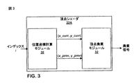
図3は、本開示の技法に従って1つまたは複数の頂点ポイントを廃棄する例示的な頂点シェーダ22Aのブロック図である。頂点シェーダ22Aは、たとえば、図2の頂点シェーダ22と対応することがある。頂点シェーダ22Aは、現在の頂点ポイントおよび少なくとも1つの追加の頂点ポイントについてディスプレイ座標空間における位置座標を計算する位置座標計算モジュール30と、計算された頂点ポイントのいずれかを廃棄すべきかどうかを判断する頂点廃棄モジュール32とを含む。
FIG. 3 is a block diagram of an
位置座標計算モジュール30は、少なくとも1つの頂点ポイントを表す1つまたは複数の頂点の属性情報を得る。図3の例では、位置座標計算モジュール30は、他の頂点ポイントの中の上記頂点ポイントの位置を示すインデックス属性情報iを得る。位置座標計算モジュール30は、そのインデックス属性情報に関連する頂点ポイント、すなわち、現在の頂点ポイントについてディスプレイ座標空間における位置座標を計算する。位置座標計算モジュール30はまた、少なくとも1つの他の頂点ポイント、たとえば、前の頂点ポイントについてディスプレイ座標空間における位置座標を計算する。図2に関して上記で詳細に説明したように、位置座標計算モジュール30は、グラフィカルソフトウェアアプリケーションによって定義された曲線を表す数式と、インデックス属性情報iに応じて計算された変数とを使用して、その位置座標を計算することができる。図3では、現在の頂点ポイントの位置座標と前の頂点ポイントの位置座標は、それぞれ、(x_curr,y_curr)と(x_prev,y_prev)として表されている。
The position coordinate
頂点廃棄モジュール32は、現在のおよび前の頂点ポイントの計算された位置座標を受信する。頂点廃棄モジュール32は、現在の頂点ポイントの計算された位置座標を前の頂点ポイントの計算された位置座標と比較し、ディスプレイ座標空間における位置座標が実質的に同じであるとき、現在の頂点ポイントを廃棄する。言い換えれば、頂点廃棄モジュール32は、x_curr=x_prevおよびy_curr=y_prevであるとき、現在の頂点ポイントを廃棄する。このようにして、頂点シェーダ22Aはディスプレイ座標空間において冗長な頂点ポイントを除去する。
Vertex discard module 32 receives the calculated position coordinates of the current and previous vertex points. Vertex discard module 32 compares the calculated position coordinates of the current vertex point with the calculated position coordinates of the previous vertex point, and when the position coordinates in the display coordinate space are substantially the same, Discard. In other words, the vertex discard module 32 discards the current vertex point when x_curr = x_prev and y_curr = y_prev. In this way, the
現在の頂点ポイントを廃棄すると、頂点廃棄モジュール32は、現在の頂点ポイントが廃棄されたことを示す廃棄信号を出力することがある。代替的に、頂点廃棄モジュール32は、現在の頂点ポイントが廃棄されたとき、いかなる信号をも出力しないことがある。頂点廃棄モジュール32が現在の頂点ポイントを廃棄しないとき、すなわち、ディスプレイ座標空間における現在のおよび前の頂点ポイントの位置座標が異なるとき、頂点廃棄モジュール32は現在の頂点ポイントの位置座標(x_curr,y_curr)を出力する。 Upon discarding the current vertex point, the vertex discard module 32 may output a discard signal indicating that the current vertex point has been discarded. Alternatively, vertex discard module 32 may not output any signal when the current vertex point is discarded. When the vertex discard module 32 does not discard the current vertex point, that is, when the position coordinates of the current and previous vertex points in the display coordinate space are different, the vertex discard module 32 determines the position coordinates (x_curr, y_curr) of the current vertex point. ) Is output.
位置座標計算モジュール30について、受信したインデックス属性情報に基づいて現在のおよび前の頂点ポイントについての位置座標を計算することに関して説明するが、位置座標計算モジュール30は、ディスプレイ座標空間における現在のおよび前の頂点ポイントについての位置座標を計算する際に使用する他の位置の属性情報を受信することができる。たとえば、位置座標計算モジュール30は、モデル座標空間における現在のおよび前の頂点ポイントの位置座標を受信し、変換式を使用してディスプレイ座標空間における現在のおよび前の頂点ポイントの位置座標を計算することができる。さらに別の例では、位置座標計算モジュール30は、ディスプレイ座標空間における現在の頂点ポイントの位置座標のみを計算することができる。この場合、位置座標計算モジュール30は、比較のために、ディスプレイ座標空間における前の頂点ポイントの前に計算された位置座標を受信することができる。
The position coordinate
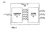
図4は、本開示の一態様による、複数の頂点ポイントを出力する例示的な頂点シェーダ22Bのブロック図である。頂点シェーダ22Bは、たとえば、図2の頂点シェーダ22と対応することがある。頂点シェーダ22Bは、複数の頂点ポイントについてディスプレイ座標空間における位置座標を計算する位置座標計算モジュール40と、計算された頂点ポイントのいずれかを廃棄すべきかどうかを判断する頂点廃棄モジュール42とを含む。
FIG. 4 is a block diagram of an exemplary vertex shader 22B that outputs a plurality of vertex points according to one aspect of the present disclosure. Vertex shader 22B may correspond to, for example, vertex shader 22 in FIG. The vertex shader 22B includes a position coordinate
位置座標計算モジュール40は、少なくとも1つの頂点ポイントを表す1つまたは複数の頂点の属性情報を得る。図4の例では、位置座標計算モジュール30は、頂点ポイントのシーケンスにおける位置を示すインデックス属性情報iを得る。位置座標計算モジュール40は、複数の頂点ポイントについてディスプレイ座標空間における位置座標を計算する。図4の例では、位置座標計算モジュール40は、5つの頂点ポイントのピクセル座標、(x1,y1)、(x2,y2)、(x3,y3)、(x4,y4)および(x5,y5)を計算する。図2に関して上記で詳細に説明したように、位置座標計算モジュール40は、グラフィカルソフトウェアアプリケーションによって定義された曲線を表す数式と、インデックス属性情報iに応じて計算された変数とを使用して、その位置座標を計算することができる。
The position coordinate
頂点廃棄モジュール42は、複数の頂点ポイントの計算された位置座標を受信し、それらの頂点ポイントのいずれかを廃棄すべきかどうかを判断する。頂点廃棄モジュール42は、たとえば、頂点ポイントの計算された位置座標(x2,y2)〜(x5,y5)の各々を、それぞれ、前の頂点ポイントの位置座標(x1,y1)〜(x4,y4)と比較することができる。頂点廃棄モジュール42は、対応する前の頂点ポイントと実質的に同じである、ディスプレイ座標空間における位置座標を有する頂点ポイントを廃棄する。このようにして、頂点シェーダ22Bはディスプレイ座標空間において冗長な頂点ポイントを除去する。 Vertex discard module 42 receives the calculated position coordinates of a plurality of vertex points and determines whether any of those vertex points should be discarded. For example, the vertex discarding module 42 converts the calculated position coordinates (x2, y2) to (x5, y5) of the vertex points into position coordinates (x1, y1) to (x4, y4) of the previous vertex points, respectively. ). Vertex discard module 42 discards vertex points having position coordinates in the display coordinate space that are substantially the same as the corresponding previous vertex points. In this way, the vertex shader 22B removes redundant vertex points in the display coordinate space.
頂点廃棄モジュール42は、さらに、頂点ポイントのうちの少なくともいくつかが、隣接する頂点ポイントをもつ直線上にあるかどうかを判断することができる。図4の例では、頂点廃棄モジュール42は、頂点ポイントの位置座標(x2,y2)〜(x4,y4)が直線上にあるかどうかを判断することができる。そうするために、頂点廃棄モジュール42は、頂点ポイントの位置座標(x2,y2)と前の頂点ポイントの位置座標(x1,y1)とを接続するラインセグメントの傾きを、後続の頂点ポイントの位置座標(x3,y3)と頂点ポイントの位置座標(x2,y2)とを接続するラインセグメントの傾きと比較することができる。両方のラインセグメントの傾きが実質的に等しい(たとえば、許容差以内である)とき、頂点廃棄モジュール42は、それらの頂点ポイントが実質的直線上にあると判断し、頂点ポイント(x2,y2)を廃棄する。頂点廃棄モジュール42は、頂点ポイントの位置座標(x3,y3)および(x4,y4)の同じ分析を実行する。(x1,y1)の前には、ラインセグメントの傾きを計算するために使用する、前の頂点ポイントについての位置座標がなく、(x5,y5)の後には、ラインセグメントの傾きを計算するために使用する、後続の頂点ポイントについての位置座標がないので、頂点廃棄モジュール42は、頂点ポイントの位置座標(x1,y1)および(x5,y5)に対してライン分析を実行しないことがある。 Vertex discard module 42 can further determine whether at least some of the vertex points are on a straight line with adjacent vertex points. In the example of FIG. 4, the vertex discard module 42 can determine whether the position coordinates (x2, y2) to (x4, y4) of the vertex points are on a straight line. In order to do so, the vertex discarding module 42 determines the inclination of the line segment connecting the position coordinates (x2, y2) of the vertex point and the position coordinates (x1, y1) of the previous vertex point, and the position of the subsequent vertex point. The coordinates (x3, y3) and the position coordinates (x2, y2) of the vertex point can be compared with the inclination of the line segment connecting them. When the slopes of both line segments are substantially equal (eg, within tolerance), vertex discard module 42 determines that the vertex points are on a substantially straight line, and vertex point (x2, y2) Discard. The vertex discard module 42 performs the same analysis of the vertex point position coordinates (x3, y3) and (x4, y4). There is no position coordinate for the previous vertex point used to calculate the slope of the line segment before (x1, y1), and to calculate the slope of the line segment after (x5, y5). Since there are no position coordinates for subsequent vertex points to use, the vertex discard module 42 may not perform line analysis on the position coordinates (x1, y1) and (x5, y5) of the vertex points.
廃棄された頂点ポイントがない場合、頂点廃棄モジュール42は、最高4つの頂点ポイントについての位置座標を出力することができる。図4に示す例では、たとえば、頂点ポイントの位置座標(x3,y3)が、重複であるか、またはその隣接頂点ポイントをもつ直線上にあるので、頂点廃棄モジュール42は頂点ポイントの位置座標(x3,y3)を廃棄する。したがって、頂点廃棄モジュール42は3つの頂点ポイントの位置座標を出力する。複数の頂点ポイントの位置座標を計算し、出力することによって、頂点シェーダ22Bは計算オーバーヘッドを低減することができる。たとえば、頂点シェーダ22Bが、最高4つの頂点ポイントについての位置座標を出力することができるとき、頂点シェーダ22Bは、計算オーバーヘッドを100%(入力頂点ポイントごとに1回のオーバーヘッド計算)から25%(4つの入力頂点ポイントごとに1回のオーバーヘッド計算)に低減することができる。図4で説明する例では、頂点シェーダ22Bは、最高4つの頂点ポイントについての位置座標を出力することができるが、頂点シェーダ22Bは、任意の数の頂点ポイントについての位置座標を出力するように構成できる。たとえば、頂点シェーダ22Bは、4つよりも多いまたは少ない頂点ポイントについての位置座標を出力するように構成できる。 If there are no discarded vertex points, vertex discard module 42 can output position coordinates for up to four vertex points. In the example shown in FIG. 4, for example, the position coordinates (x3, y3) of the vertex point are overlapped or on a straight line having the adjacent vertex points. Discard x3, y3). Therefore, the vertex discard module 42 outputs the position coordinates of the three vertex points. By calculating and outputting the position coordinates of a plurality of vertex points, the vertex shader 22B can reduce the calculation overhead. For example, when vertex shader 22B can output position coordinates for up to four vertex points, vertex shader 22B can compute from 100% (one overhead calculation per input vertex point) to 25% ( Can be reduced to one overhead calculation for every four input vertex points. In the example illustrated in FIG. 4, the vertex shader 22B can output position coordinates for up to four vertex points, but the vertex shader 22B outputs position coordinates for an arbitrary number of vertex points. Can be configured. For example, vertex shader 22B can be configured to output position coordinates for more or less than four vertex points.
図5は、ディスプレイ座標空間において繰返しの頂点ポイントを廃棄する頂点シェーダ22の例示的な動作を示す流れ図である。頂点シェーダ22は、レンダリングすべき曲線上にある少なくとも1つの頂点ポイントを定義する1つまたは複数の頂点の属性情報を得る(50)。頂点の属性情報は、頂点ポイントのシーケンスにおける現在の頂点ポイントの位置を示す、現在の頂点ポイントに関連するインデックス番号などの、位置の属性情報を含む。別の例では、位置の属性情報は、2D曲線の場合は(x,y)座標、または3D曲線の場合は(x,y,z)座標などの、位置座標とすることができる。頂点の属性情報は、さらに、1つまたは複数のカラー属性情報、1つまたは複数のテクスチャ属性情報、1つまたは複数のライティング属性情報など、頂点ポイントに関連する他の情報を含むことができる。頂点シェーダ22は、頂点の属性情報のシーケンスをデバイスメモリ8から得るか、CPU6からのコマンドから得るか、またはインデックス番号の場合は、GPU10内のカウンタ28から得ることができる。
FIG. 5 is a flow diagram illustrating an exemplary operation of vertex shader 22 that discards repeated vertex points in the display coordinate space. Vertex shader 22 obtains attribute information for one or more vertices that define at least one vertex point on the curve to be rendered (50). Vertex attribute information includes position attribute information such as an index number associated with the current vertex point that indicates the position of the current vertex point in the sequence of vertex points. In another example, the position attribute information may be position coordinates, such as (x, y) coordinates for 2D curves or (x, y, z) coordinates for 3D curves. The vertex attribute information may further include other information related to the vertex point, such as one or more color attribute information, one or more texture attribute information, one or more lighting attribute information. The vertex shader 22 can obtain a sequence of vertex attribute information from the device memory 8, a command from the CPU 6, or, in the case of an index number, a
頂点シェーダ22は、ディスプレイ座標空間における現在の頂点ポイントの位置座標を計算する(52)。現在の頂点ポイントは、頂点シェーダ22が現在作用している頂点ポイントである。頂点シェーダ22は、ディスプレイ座標空間における前の頂点ポイントの位置座標をも計算する(54)。前の頂点ポイントは、現在の頂点ポイントの直前にくる頂点ポイントとすることができる。たとえば、インデックス属性情報の場合、頂点シェーダ22は、たとえば、図2の擬似コードに関して示し、説明したように、グラフィカルソフトウェアアプリケーションによって定義された曲線を表す数式と、インデックス属性情報iに応じて計算された変数とを使用して、その位置座標を計算することができる。現在のおよび前の頂点ポイントの位置座標は、ディスプレイ上のロケーション、たとえば、ディスプレイ上に曲線を提示するために使用される、ピクセルのアレイの中でのピクセルロケーションを表すことができる。 The vertex shader 22 calculates the position coordinates of the current vertex point in the display coordinate space (52). The current vertex point is the vertex point at which the vertex shader 22 is currently operating. The vertex shader 22 also calculates the position coordinates of the previous vertex point in the display coordinate space (54). The previous vertex point may be the vertex point that comes immediately before the current vertex point. For example, in the case of index attribute information, the vertex shader 22 is calculated in accordance with, for example, a mathematical expression representing a curve defined by a graphical software application and the index attribute information i, as shown and described with respect to the pseudo code of FIG. Can be used to calculate the position coordinates. The position coordinates of the current and previous vertex points can represent a location on the display, eg, a pixel location in an array of pixels that is used to present a curve on the display.
頂点シェーダ22は、現在のおよび前の頂点ポイントのディスプレイ位置座標が実質的に同じであるかどうかを判断する(56)。たとえば、頂点シェーダ22は、現在の頂点ポイントの計算されたディスプレイ位置座標を前の頂点ポイントの計算されたディスプレイ位置座標と比較して、それらのディスプレイ位置座標が実質的に同じであるかどうか、たとえば、許容しきい値以内であるかどうかを判断することができる。それらのディスプレイ位置座標が実質的に同じであるとき、頂点シェーダ22は現在の頂点ポイントを廃棄する(57)。いくつかの例では、頂点シェーダ22は、現在の頂点ポイントが廃棄されたことを示す廃棄信号を出力することがある。代替的に、頂点シェーダ22は何も出力しないことがあり、たとえば、頂点ポイントが廃棄されたことを他のモジュールまたは要素に示すことなしに頂点ポイントを廃棄することがある。このようにして、頂点シェーダ22はディスプレイ座標空間において冗長な頂点ポイントを除去する。 Vertex shader 22 determines whether the display position coordinates of the current and previous vertex points are substantially the same (56). For example, the vertex shader 22 compares the calculated display position coordinates of the current vertex point with the calculated display position coordinates of the previous vertex point to determine whether those display position coordinates are substantially the same, For example, it can be determined whether it is within an acceptable threshold. When their display position coordinates are substantially the same, vertex shader 22 discards the current vertex point (57). In some examples, vertex shader 22 may output a discard signal indicating that the current vertex point has been discarded. Alternatively, vertex shader 22 may output nothing, for example, discarding a vertex point without indicating to other modules or elements that the vertex point has been discarded. In this way, the vertex shader 22 removes redundant vertex points in the display coordinate space.
頂点シェーダ22は、それらのディスプレイ位置座標が実質的に同じでないと判断したとき、ディスプレイ座標空間における現在の頂点ポイントの位置座標を出力する(58)。図5の流れ図では、頂点シェーダ22が、単一の頂点ポイントを廃棄すべきか否かに関する判断を行うことについて説明するが、頂点シェーダは、上記で詳細に説明したように、2つ以上の頂点ポイントについて同時にそのような判断を行うように構成できる。たとえば、頂点シェーダ22は、N個の頂点ポイントについての位置座標、ならびにN個の頂点ポイントの直前にある1つの頂点ポイントの位置座標を計算することによって、N個の頂点ポイントを廃棄すべきかどうかを同時に判断するように構成できる。頂点シェーダ22は、N個の頂点ポイントの各々の位置座標を、対応する前の頂点ポイントの位置座標と比較して、N個の頂点ポイントのいずれかが重複であるかどうかを判断することができる。頂点シェーダ22は、(いずれも重複でない場合は)最高N個の頂点ポイントを出力することができる。このようにして、頂点シェーダ22は、計算オーバーヘッドを100%(入力頂点ポイントごとに1回のオーバーヘッド計算)から25%(4つの入力頂点ポイントごとに1回のオーバーヘッド計算)に低減することができる。 When the vertex shader 22 determines that the display position coordinates are not substantially the same, it outputs the position coordinates of the current vertex point in the display coordinate space (58). The flow diagram of FIG. 5 illustrates that the vertex shader 22 makes a determination as to whether a single vertex point should be discarded, but the vertex shader has more than one vertex as described in detail above. It can be configured to make such a determination for points simultaneously. For example, whether vertex shader 22 should discard N vertex points by calculating the position coordinates for N vertex points, as well as the position coordinates of one vertex point immediately preceding N vertex points. Can be determined at the same time. Vertex shader 22 may compare the position coordinates of each of the N vertex points with the position coordinates of the corresponding previous vertex point to determine whether any of the N vertex points is an overlap. it can. Vertex shader 22 can output up to N vertex points (if none are overlapping). In this way, the vertex shader 22 can reduce the computation overhead from 100% (one overhead calculation for each input vertex point) to 25% (one overhead calculation for every four input vertex points). .
図6は、ディスプレイ座標空間において直線上にある少なくともいくつかの頂点ポイントを廃棄する頂点シェーダ22の例示的な動作を示す流れ図である。頂点シェーダ22は、レンダリングすべき曲線上にある少なくとも1つの頂点ポイントを定義する1つまたは複数の頂点の属性情報を得る(60)。頂点の属性情報は、頂点ポイントのシーケンスにおける現在の頂点ポイントの位置を示す、現在の頂点ポイントに関連するインデックス番号などの、位置の属性情報を含む。別の例では、位置の属性情報は、2D曲線の場合は(x,y)座標、または3D曲線の場合は(x,y,z)座標などの、位置座標とすることができる。頂点の属性情報は、さらに、法線属性情報、1つまたは複数のカラー属性情報、1つまたは複数のテクスチャ属性情報、1つまたは複数のライティング属性情報など、頂点ポイントに関連する他の情報を含むことができる。頂点シェーダ22は、頂点の属性情報のシーケンスをデバイスメモリ8から得るか、CPU6からのコマンドから得るか、またはインデックス番号の場合は、GPU10内から得ることができる。 FIG. 6 is a flow diagram illustrating an exemplary operation of vertex shader 22 that discards at least some vertex points that are on a straight line in the display coordinate space. Vertex shader 22 obtains attribute information for one or more vertices defining at least one vertex point on the curve to be rendered (60). Vertex attribute information includes position attribute information such as an index number associated with the current vertex point that indicates the position of the current vertex point in the sequence of vertex points. In another example, the position attribute information may be position coordinates, such as (x, y) coordinates for 2D curves or (x, y, z) coordinates for 3D curves. Vertex attribute information further includes other information related to the vertex point, such as normal attribute information, one or more color attribute information, one or more texture attribute information, one or more lighting attribute information, etc. Can be included. The vertex shader 22 can obtain a sequence of vertex attribute information from the device memory 8, a command from the CPU 6, or an index number from the GPU 10.
頂点シェーダ22は、ディスプレイ座標空間における現在の頂点ポイントの位置座標を計算する(62)。現在の頂点ポイントは、頂点シェーダ22が現在作用している頂点ポイントである。頂点シェーダ22は、ディスプレイ座標空間における前の頂点ポイントの位置座標をも計算する(64)。前の頂点ポイントは、現在の頂点ポイントの直前にくる頂点ポイントとすることができる。頂点シェーダ22は、ディスプレイ座標空間における後続の頂点ポイントの位置座標をも計算する(66)。後続の頂点ポイントは、現在の頂点ポイントの直後にくる頂点ポイントとすることができる。たとえば、インデックス属性情報の場合、頂点シェーダ22は、たとえば、図2の擬似コードに関して示し、説明したように、グラフィカルソフトウェアアプリケーションによって定義された曲線を表す数式と、インデックス属性情報iに応じて計算された変数とを使用して、その位置座標を計算することができる。 The vertex shader 22 calculates the position coordinates of the current vertex point in the display coordinate space (62). The current vertex point is the vertex point at which the vertex shader 22 is currently operating. The vertex shader 22 also calculates the position coordinates of the previous vertex point in the display coordinate space (64). The previous vertex point may be the vertex point that comes immediately before the current vertex point. Vertex shader 22 also calculates the position coordinates of subsequent vertex points in the display coordinate space (66). Subsequent vertex points can be vertex points that immediately follow the current vertex point. For example, in the case of index attribute information, the vertex shader 22 is calculated in accordance with, for example, a mathematical expression representing a curve defined by a graphical software application and the index attribute information i, as shown and described with respect to the pseudo code of FIG. Can be used to calculate the position coordinates.
頂点シェーダ22は、それらの頂点ポイントが実質的直線上にあるかどうかを判断する(68)。たとえば、頂点シェーダ22は、現在の頂点ポイントと前の頂点ポイントとの位置座標を接続するラインセグメントの傾きを、後続の頂点ポイントと現在の頂点ポイントとの位置座標を接続するラインセグメントの傾きと比較することができる。両方のラインセグメントの傾きが実質的に等しい(たとえば、許容差以内である)とき、頂点シェーダ22は、それらの頂点ポイントが実質的直線上にあると判断する。 Vertex shader 22 determines whether those vertex points are on a substantially straight line (68). For example, the vertex shader 22 indicates the inclination of the line segment connecting the position coordinates of the current vertex point and the previous vertex point, and the inclination of the line segment connecting the position coordinates of the subsequent vertex point and the current vertex point. Can be compared. When the slopes of both line segments are substantially equal (eg, within tolerance), vertex shader 22 determines that the vertex points are on a substantially straight line.
頂点シェーダ22は、それらの頂点ポイントが実質的直線上にあると判断したとき、現在の頂点ポイントを廃棄する(70)。前の頂点ポイントと後続の頂点ポイントとを接続するラインセグメントは、前の頂点ポイントと現在の頂点ポイントとを接続し、現在の頂点ポイントと後続の頂点ポイントとを接続する、ラインセグメントと同じであるので、現在の頂点ポイントを廃棄することは、ディスプレイにレンダリングされる画像に影響を及ぼさない。頂点シェーダ22は、それらの頂点ポイントが実質的直線上にあると判断したとき、ディスプレイ座標空間における現在の頂点ポイントの位置座標を出力する(72)。頂点シェーダ22は、図5に関して説明したように、冗長な頂点ポイントを除去することなしに、または冗長な頂点ポイントを除去することに加えて、実質的直線上にある頂点ポイントを除去することができる。 When vertex shader 22 determines that the vertex points are on a substantially straight line, it discards the current vertex points (70). The line segment connecting the previous vertex point and the subsequent vertex point is the same as the line segment connecting the previous vertex point and the current vertex point and connecting the current vertex point and the subsequent vertex point. As such, discarding the current vertex point does not affect the image rendered on the display. When the vertex shader 22 determines that the vertex points are on a substantially straight line, it outputs the position coordinates of the current vertex point in the display coordinate space (72). Vertex shader 22 may remove vertex points that are substantially on a straight line without removing redundant vertex points or in addition to removing redundant vertex points, as described with respect to FIG. it can.
本明細書で説明した技法は、ハードウェア、ソフトウェア、ファームウェア、またはそれらの任意の組合せで実装できる。モジュールまたは構成要素として説明する機能は、集積論理デバイスに一緒に、または個別であるが相互運用可能な論理デバイスとして別々に実装できる。場合によっては、様々な特徴は、集積回路チップまたはチップセットなどの集積回路デバイスとして実装できる。ソフトウェアで実装した場合、本技法は、実行されたときに、上記で説明した方法の1つまたは複数を実行する命令を備えるコンピュータ可読媒体によって少なくとも部分的に実現できる。コンピュータ可読媒体は、パッケージング材料を含むことができる、コンピュータプログラム製品の一部をなすことができる。コンピュータ可読媒体は、シンクロナスダイナミックランダムアクセスメモリ(SDRAM)などのランダムアクセスメモリ(RAM)、読取り専用メモリ(ROM)、不揮発性ランダムアクセスメモリ(NVRAM)、電気的消去可能プログラマブル読取り専用メモリ(EEPROM)、フラッシュメモリ、磁気または光学データ記憶媒体などを備えることができる。本技法は、追加または代替として、命令またはデータ構造の形態でコードを搬送または伝達し、コンピュータによってアクセス、読取り、および/または実行できるコンピュータ可読通信媒体によって、少なくとも部分的に実現できる。 The techniques described herein may be implemented in hardware, software, firmware, or any combination thereof. Functions described as modules or components can be implemented together in an integrated logical device or separately as a separate but interoperable logical device. In some cases, the various features can be implemented as an integrated circuit device, such as an integrated circuit chip or chipset. When implemented in software, the techniques may be implemented at least in part by a computer-readable medium comprising instructions that, when executed, perform one or more of the methods described above. The computer readable medium can form part of a computer program product that can include packaging material. Computer readable media include random access memory (RAM) such as synchronous dynamic random access memory (SDRAM), read only memory (ROM), non-volatile random access memory (NVRAM), electrically erasable programmable read only memory (EEPROM) , Flash memory, magnetic or optical data storage media, and the like. The techniques can additionally or alternatively be implemented at least in part by a computer readable communication medium that carries or conveys code in the form of instructions or data structures and that can be accessed, read and / or executed by a computer.
コードは、1つまたは複数のDSP、汎用マイクロプロセッサ、ASIC、フィールドプログラマブル論理アレイFPGA、あるいは他の等価な集積または個別論理回路など、1つまたは複数のプロセッサによって実行できる。したがって、本明細書で使用する「プロセッサ」という用語は、前述の構造、または本明細書で説明する技法の実装に好適な他の構造のいずれかを指すことがある。さらに、いくつかの態様では、本明細書で説明する機能を、グラフィックス画像をテッセレーションするように構成された、専用のソフトウェアアプリケーションまたはハードウェアモジュールの内部に与えることができる。したがって、本開示はまた、本開示で説明した技法の1つまたは複数を実装する回路を含む様々な集積回路デバイスのいずれかを企図する。そのような回路は、単一の集積回路チップまたは複数の相互運用可能な集積回路チップで提供できる。 The code may be executed by one or more processors, such as one or more DSPs, general purpose microprocessors, ASICs, field programmable logic arrays FPGAs, or other equivalent integrated or discrete logic circuits. Thus, as used herein, the term “processor” may refer to either the structure described above or other structure suitable for implementation of the techniques described herein. Further, in some aspects, the functionality described herein may be provided within a dedicated software application or hardware module that is configured to tessellate graphics images. Accordingly, this disclosure also contemplates any of a variety of integrated circuit devices that include circuitry that implements one or more of the techniques described in this disclosure. Such a circuit can be provided in a single integrated circuit chip or multiple interoperable integrated circuit chips.
様々な態様について説明した。これらおよび他の態様は添付した本願の特許請求の範囲内に入る。なお、本願の出願当初の請求項と同一の記載を「その他の実施例」として、以下に付記する。
[その他の実施例1]
下記を備える方法:
レンダリングすべき曲線上にある複数の頂点ポイントの各々についての位置座標を判断すること;
前記複数の頂点ポイントの少なくとも一部の前記位置座標を分析すること;および、
前記分析に基づいて前記複数の頂点ポイントのうちの少なくとも1つを廃棄すること。
[その他の実施例2]
前記複数の頂点ポイントの各々の前記位置座標を分析することが、前記複数の頂点ポイントのうちの第1の頂点ポイントの第1の位置座標を前記複数の頂点ポイントのうちの第2の頂点ポイントの第2の位置座標と比較することを備え、ただし、前記第1の頂点ポイントが前記第2の頂点ポイントの直前にあり、
少なくとも1つの頂点ポイントを廃棄することは、前記第1および第2の位置座標が実質的に同じであるとき、前記第2の頂点ポイントを廃棄することを備える、
その他の実施例1に記載の方法。
[その他の実施例3]
前記複数の頂点ポイントの各々の前記位置座標を分析することが、前記複数の頂点ポイントのうちの第3の頂点ポイントの第3の位置座標を前記第2の位置座標と比較することをさらに備え、ただし、前記第2の頂点ポイントが前記第3の頂点ポイントの直前にあり、
少なくとも1つの頂点ポイントを廃棄することは、前記第2および第3の位置座標が実質的に同じであるとき、前記第3の頂点ポイントを廃棄することを備える、
その他の実施例2に記載の方法。
[その他の実施例4]
下記をさらに備える、その他の実施例3に記載の方法:
前記第1および第2の位置座標が実質的に同じでないとき、前記第2の頂点ポイントの前記位置座標を出力すること;および、
前記第2および第3の位置座標が実質的に同じでないとき、前記第3の頂点ポイントの前記位置座標を同時に出力すること。
[その他の実施例5]
少なくとも1つの頂点ポイントを廃棄することが、前の頂点ポイントと後続の頂点ポイントとによって形成される直線上に実質的にある少なくとも1つの頂点ポイントを廃棄することを備える、その他の実施例1に記載の方法。
[その他の実施例6]
前記複数の頂点ポイントの各々の前記位置座標を分析することが、
第1の頂点ポイントの位置座標と第2の頂点ポイントの位置座標との間の第1の傾きを計算することと、
前記第2の頂点ポイントの前記位置座標と第3の頂点ポイントの位置座標との間の第2の傾きを計算することと
を備え、
少なくとも1つの頂点ポイントを廃棄することは、前記第1および第2の計算された傾きが実質的に同じであるとき、前記第2の頂点ポイントを廃棄することを備える、
その他の実施例1に記載の方法。
[その他の実施例7]
前記複数の頂点ポイントの各々の前記位置座標を分析することが、前記第1の頂点ポイントの前記位置座標を前記第2の頂点ポイントの前記位置座標と比較することをさらに備え、
少なくとも1つの頂点ポイントを廃棄することは、前記第1および第2の位置座標が実質的に同じであるとき、前記第2の頂点ポイントを廃棄することを備える、
その他の実施例6に記載の方法。
[その他の実施例8]
前記複数の頂点ポイントにおける現在の頂点ポイントの順序位置を示すインデックス値を得ることをさらに備え、前記位置座標を前記判断することが、前記インデックス値に応じて複数の頂点ポイントの各々についてディスプレイ座標空間における位置座標を判断することを備える、その他の実施例1に記載の方法。
[その他の実施例9]
前記インデックス値を得ることが、前記インデックス値をグラフィックス処理ユニット(GPU)のカウンタから得ることを備える、その他の実施例8に記載の方法。
[その他の実施例10]
前記曲線をディスプレイに表示するために前記曲線をレンダリングすることをさらに備える、その他の実施例1に記載の方法。
[その他の実施例11]
前記頂点ポイントが2次元曲線上にあり、
前記複数の頂点ポイントの各々の前記位置座標を分析することが、3次元(3D)グラフィックス処理ユニット(GPU)の頂点シェーダを用いて、前記複数の頂点ポイントの各々の前記位置座標を分析することを備え、
前記複数の頂点ポイントのうちの少なくとも1つを廃棄することが、前記3D GPUの前記頂点シェーダを用いて、前記分析に基づいて前記複数の頂点ポイントのうちの少なくとも1つを廃棄することを備える、その他の実施例1に記載の方法。
[その他の実施例12]
前記複数の頂点ポイントのうちの少なくとも1つを廃棄することが、前記複数の頂点ポイントのうちの少なくとも1つの他の頂点ポイントと同じピクセル位置にマッピングする、前記複数の頂点ポイントのうちの少なくとも1つを廃棄することを備える、その他の実施例1に記載の方法。
[その他の実施例13]
下記を実行する処理ユニットを備えるデバイス:
レンダリングすべき曲線上にある複数の頂点ポイントの各々についての位置座標を判断すること;
前記複数の頂点ポイントの少なくとも一部の前記位置座標を分析すること;および、
前記分析に基づいて前記複数の頂点ポイントのうちの少なくとも1つを廃棄すること。
[その他の実施例14]
前記処理ユニットが下記を実行するその他の実施例13に記載のデバイス:
前記複数の頂点ポイントのうちの第1の頂点ポイントの第1の位置座標を前記複数の頂点ポイントのうちの第2の頂点ポイントの第2の位置座標と比較すること、ただし、前記第1の頂点ポイントが前記第2の頂点ポイントの直前にある;および、
前記第1および第2の位置座標が実質的に同じであるとき、前記第2の頂点ポイントを廃棄すること。
[その他の実施例15]
前記処理ユニットが下記を実行するその他の実施例14に記載のデバイス:
前記複数の頂点ポイントのうちの第3の頂点ポイントの第3の位置座標を前記第2の位置座標と比較すること、ただし、前記第2の頂点ポイントが前記第3の頂点ポイントの直前にある;および、
前記第2および第3の位置座標が実質的に同じであるとき、前記第3の頂点ポイントを廃棄すること。
[その他の実施例16]
前記処理ユニットが下記を実行するその他の実施例15に記載のデバイス:
前記第1および第2の位置座標が実質的に同じでないとき、前記第2の頂点ポイントの前記位置座標を出力すること;および、
前記第2および第3の位置座標が実質的に同じでないとき、前記第3の頂点ポイントの前記位置座標を同時に出力すること。
[その他の実施例17]
前記処理ユニットが、前の頂点ポイントと後続の頂点ポイントとによって形成される直線上に実質的にある少なくとも1つの頂点ポイントを廃棄する、その他の実施例13に記載のデバイス。
[その他の実施例18]
前記処理ユニットが下記を実行するその他の実施例13に記載のデバイス:
第1の頂点ポイントの位置座標と第2の頂点ポイントの位置座標との間の第1の傾きを計算すること;
前記第2の頂点ポイントの前記位置座標と第3の頂点ポイントの位置座標との間の第2の傾きを計算すること;および、
前記第1および第2の計算された傾きが実質的に同じであるとき、前記第2の頂点ポイントを廃棄すること。
[その他の実施例19]
前記処理ユニットが下記を実行するその他の実施例18に記載のデバイス:
前記第1の頂点ポイントの前記位置座標を前記第2の頂点ポイントの前記位置座標と比較すること;および、
前記第1および第2の位置座標が実質的に同じであるとき、前記第2の頂点ポイントを廃棄すること。
[その他の実施例20]
前記処理ユニットが下記を実行するその他の実施例13に記載のデバイス:
前記複数の頂点ポイントにおける現在の頂点ポイントの順序位置を示すインデックス値を得ること;および、
前記インデックス値に応じて複数の頂点ポイントの各々についてディスプレイ座標空間における位置座標を判断すること。
[その他の実施例21]
前記処理ユニットが、前記インデックス値を発生するカウンタを含む、その他の実施例20に記載のデバイス。
[その他の実施例22]
前記処理ユニットが、前記曲線をディスプレイに提示するために前記曲線をレンダリングする、その他の実施例13に記載のデバイス。
[その他の実施例23]
前記頂点ポイントが2次元曲線上にあり、前記処理ユニットが3次元(3D)グラフィックス処理ユニット(GPU)を備える、その他の実施例13に記載のデバイス。
[その他の実施例24]
その他の実施例13に記載のデバイス、ただし、前記処理ユニットが3次元(3D)グラフィックス処理ユニット(GPU)の頂点シェーダを備え、前記頂点シェーダが下記をさらに備える:
レンダリングすべき曲線上にある複数の頂点ポイントの各々についてディスプレイ座標空間における位置座標を判断する位置座標計算モジュール;
前記複数の頂点ポイントの各々の前記位置座標を分析し、前記分析に基づいて前記複数の頂点ポイントのうちの少なくとも1つを廃棄する頂点廃棄モジュール。
[その他の実施例25]
前記デバイスがワイヤレス通信デバイスを備える、その他の実施例13に記載のデバイス。
[その他の実施例26]
前記デバイスが集積回路デバイスを備える、その他の実施例13に記載のデバイス。
[その他の実施例27]
前記複数の頂点ポイントのうちの少なくとも1つを廃棄することが、前記複数の頂点ポイントのうちの少なくとも1つの他の頂点ポイントと同じピクセル位置にマッピングする、前記複数の頂点ポイントのうちの少なくとも1つを廃棄することを備える、その他の実施例13に記載のデバイス。
[その他の実施例28]
実行された際に、下記動作を少なくとも1つのプロセッサに実行させる命令を備えるコンピュータ可読媒体:
レンダリングすべき曲線上にある複数の頂点ポイントの各々についての位置座標を判断すること;
前記複数の頂点ポイントの少なくとも一部分の前記位置座標を分析すること;および、
前記分析に基づいて前記複数の頂点ポイントのうちの少なくとも1つを廃棄すること。
[その他の実施例29]
前記複数の頂点ポイントのうちの少なくとも1つを廃棄することが、前記複数の頂点ポイントのうちの少なくとも1つの他の頂点ポイントと同じピクセル位置にマッピングする、前記複数の頂点ポイントのうちの少なくとも1つを廃棄することを備える、その他の実施例28に記載のデバイス。
[その他の実施例30]
その他の実施例28に記載のコンピュータ可読媒体、ただし、
前記複数の頂点ポイントの各々の前記位置座標を分析することを前記プロセッサに行わせる命令が、前記複数の頂点ポイントのうちの第1の頂点ポイントの第1の位置座標を前記複数の頂点ポイントのうちの第2の頂点ポイントの第2の位置座標と比較することを前記プロセッサに行わせる命令を備え、ただし、前記第1の頂点ポイントが前記第2の頂点ポイントの直前にあり、
少なくとも1つの頂点ポイントを廃棄することを前記プロセッサに実行させる命令は、前記第1および第2の位置座標が実質的に同じであるとき、前記第2の頂点ポイントを廃棄することを前記プロセッサに行わせる命令を備える。
[その他の実施例31]
少なくとも1つの頂点ポイントを廃棄することを前記プロセッサに行わせる命令が、前の頂点ポイントと後続の頂点ポイントとによって形成される直線上に実質的にある少なくとも1つの頂点ポイントを廃棄することを前記プロセッサに行わせる命令を備える、その他の実施例28に記載のコンピュータ可読媒体。
[その他の実施例32]
その他の実施例28に記載のコンピュータ可読媒体、ただし、前記複数の頂点ポイントの各々の前記位置座標を分析することを前記プロセッサに実行させる命令が、下記動作を前記プロセッサに実行させる命令を備える:
第1の頂点ポイントの位置座標と第2の頂点ポイントの位置座標との間の第1の傾きを計算すること;および、
前記第2の頂点ポイントの前記位置座標と第3の頂点ポイントの位置座標との間の第2の傾きを計算すること、
なお、少なくとも1つの頂点ポイントを廃棄することを前記プロセッサに実行させる命令は、前記第1および第2の計算された傾きが実質的に同じであるとき、前記第2の頂点ポイントを廃棄することを前記プロセッサに行わせる命令を備える。
[その他の実施例33]
その他の実施例32に記載のコンピュータ可読媒体、ただし、
前記複数の頂点ポイントの各々の前記位置座標を分析することを前記プロセッサに実行させる命令は、前記第1の頂点ポイントの前記位置座標を前記第2の頂点ポイントの前記位置座標と比較することを前記プロセッサに実行させる命令をさらに備え、
少なくとも1つの頂点ポイントを廃棄することを前記プロセッサに行わせる命令は、前記第1および第2の位置座標が実質的に同じであるとき、前記第2の頂点ポイントを廃棄することを前記プロセッサに実行させる命令を備える。
[その他の実施例34]
前記複数の頂点ポイントにおける現在の頂点ポイントの順序位置を示すインデックス値を得ることを前記プロセッサに実行させる命令をさらに備え、前記位置座標を前記判断することを前記プロセッサに実行させる命令が、前記インデックス値に応じて複数の頂点ポイントの各々についてディスプレイ座標空間における位置座標を判断することを前記プロセッサに実行させる命令を備える、その他の実施例28に記載のコンピュータ可読媒体。
[その他の実施例35]
前記インデックス値を得ることを前記プロセッサに実行させる命令が、前記インデックス値をグラフィックス処理ユニット(GPU)のカウンタから得ることを前記プロセッサに実行させる命令を備える、その他の実施例34に記載のコンピュータ可読媒体。
[その他の実施例36]
前記曲線をディスプレイに提示するために前記曲線をレンダリングすることを前記プロセッサに実行させる命令をさらに備える、その他の実施例28に記載のコンピュータ可読媒体。
[その他の実施例37]
その他の実施例28に記載のコンピュータ可読媒体、ただし、
前記複数の頂点ポイントの各々の前記位置座標を分析することを前記プロセッサに行わせる命令は、3次元(3D)グラフィックス処理ユニット(GPU)の頂点シェーダを用いて、前記複数の頂点ポイントの各々の前記位置座標を分析することを前記プロセッサに実行させる命令を備え、
前記複数の頂点ポイントのうちの少なくとも1つを廃棄することを前記プロセッサに実行させる命令は、前記3D GPUの前記頂点シェーダを用いて、前記分析に基づいて前記複数の頂点ポイントのうちの少なくとも1つを廃棄することを前記プロセッサに実行させる命令を備える。
[その他の実施例38]
下記手段を備えるデバイス:
レンダリングすべき曲線上にある複数の頂点ポイントの各々についての位置座標を判断するための手段;
前記複数の頂点ポイントの少なくとも一部分の前記位置座標を分析するための手段;および、
前記分析に基づいて前記複数の頂点ポイントのうちの少なくとも1つを廃棄するための手段。
[その他の実施例39]
その他の実施例38に記載のデバイス、ただし、
前記分析手段は、前記複数の頂点ポイントのうちの第1の頂点ポイントの第1の位置座標を前記複数の頂点ポイントのうちの第2の頂点ポイントの第2の位置座標と比較し、前記第1の頂点ポイントが前記第2の頂点ポイントの直前にあり、
前記廃棄手段は、前記第1および第2の位置座標が実質的に同じであるとき、前記第2の頂点ポイントを廃棄する。
[その他の実施例40]
その他の実施例39に記載のデバイス、ただし、
前記分析手段は、前記複数の頂点ポイントのうちの第3の頂点ポイントの第3の位置座標を前記第2の位置座標と比較し、前記第2の頂点ポイントが前記第3の頂点ポイントの直前にあり、
前記廃棄手段は、前記第2および第3の位置座標が実質的に同じであるとき、前記第3の頂点ポイントを廃棄する。
[その他の実施例41]
前記第1および第2の位置座標が実質的に同じでないとき、前記第2の頂点ポイントの前記位置座標を出力するための手段をさらに備え、
前記出力するための手段は、前記第2および第3の位置座標が実質的に同じでないとき、前記第3の頂点ポイントの前記位置座標を同時に出力する、
その他の実施例40に記載のデバイス。
[その他の実施例42]
前記廃棄手段が、前の頂点ポイントと後続の頂点ポイントとによって形成される直線上に実質的にある少なくとも1つの頂点ポイントを廃棄する、その他の実施例38に記載のデバイス。
[その他の実施例43]
その他の実施例38に記載のデバイス、ただし、
前記分析手段は、第1の頂点ポイントの位置座標と第2の頂点ポイントの位置座標との間の第1の傾きを計算し、前記第2の頂点ポイントの前記位置座標と第3の頂点ポイントの位置座標との間の第2の傾きを計算し、
前記廃棄手段は、前記第1および第2の計算された傾きが実質的に等しいとき、前記第2の頂点ポイントを廃棄する。
[その他の実施例44]
その他の実施例43に記載のデバイス、ただし、
前記分析手段は、前記第1の頂点ポイントの前記位置座標を前記第2の頂点ポイントの前記位置座標と比較し、
前記廃棄手段は、前記第1および第2の位置座標が実質的に同じであるとき、前記第2の頂点ポイントを廃棄する。
[その他の実施例45]
前記複数の頂点ポイントにおける現在の頂点ポイントの順序位置を示すインデックス値を得るための手段をさらに備え、前記判断手段が、前記インデックス値に応じて複数の頂点ポイントの各々についてディスプレイ座標空間における位置座標を判断する、その他の実施例38に記載のデバイス。
[その他の実施例46]
前記インデックス値をグラフィックス処理ユニット(GPU)内で発生するための手段をさらに備える、その他の実施例45に記載のデバイス。
[その他の実施例47]
前記曲線をディスプレイに提示するために前記曲線をレンダリングするための手段をさらに備える、その他の実施例38に記載のデバイス。
[その他の実施例48]
前記曲線が2次元曲線であり、前記廃棄手段が3次元(3D)グラフィックス処理ユニット(GPU)の頂点シェーダを備える、その他の実施例38に記載のデバイス。
Various aspects have been described. These and other aspects are within the scope of the appended claims. The same description as the claims at the beginning of the filing of the present application will be appended as “other embodiments”.
[Other Example 1]
A method comprising:
Determining the position coordinates for each of a plurality of vertex points on the curve to be rendered;
Analyzing the position coordinates of at least a portion of the plurality of vertex points; and
Discarding at least one of the plurality of vertex points based on the analysis;
[Other Example 2]
Analyzing the position coordinates of each of the plurality of vertex points to determine a first position coordinate of a first vertex point of the plurality of vertex points as a second vertex point of the plurality of vertex points; The first vertex point is immediately before the second vertex point, and
Discarding at least one vertex point comprises discarding the second vertex point when the first and second position coordinates are substantially the same.
Other methods described in Example 1.
[Other Example 3]
Analyzing the position coordinates of each of the plurality of vertex points further comprises comparing a third position coordinate of a third vertex point of the plurality of vertex points with the second position coordinate. , Provided that the second vertex point is immediately before the third vertex point;
Discarding at least one vertex point comprises discarding the third vertex point when the second and third position coordinates are substantially the same.
Other methods described in Example 2.
[Other Example 4]
Other methods described in Example 3 further comprising:
Outputting the position coordinates of the second vertex point when the first and second position coordinates are not substantially the same; and
Outputting the position coordinates of the third vertex point simultaneously when the second and third position coordinates are not substantially the same;
[Other Example 5]
In another embodiment 1, discarding at least one vertex point comprises discarding at least one vertex point that is substantially on a straight line formed by a previous vertex point and a subsequent vertex point. The method described.
[Other Example 6]
Analyzing the position coordinates of each of the plurality of vertex points;
Calculating a first slope between the position coordinates of the first vertex point and the position coordinates of the second vertex point;
Calculating a second slope between the position coordinates of the second vertex point and the position coordinates of a third vertex point;
With
Discarding at least one vertex point comprises discarding the second vertex point when the first and second calculated slopes are substantially the same.
Other methods described in Example 1.
[Other Example 7]
Analyzing the position coordinates of each of the plurality of vertex points further comprises comparing the position coordinates of the first vertex point with the position coordinates of the second vertex point;
Discarding at least one vertex point comprises discarding the second vertex point when the first and second position coordinates are substantially the same.
Other methods described in Example 6.
[Other Example 8]
Obtaining an index value indicating an order position of a current vertex point in the plurality of vertex points, wherein the determining the position coordinate is a display coordinate space for each of the plurality of vertex points according to the index value; The method of other embodiment 1, comprising determining a position coordinate at.
[Other Example 9]
9. The method of other embodiment 8, wherein obtaining the index value comprises obtaining the index value from a graphics processing unit (GPU) counter.
[Other Example 10]
The method of other embodiment 1, further comprising rendering the curve to display the curve on a display.
[Other Example 11]
The vertex point is on a two-dimensional curve;
Analyzing the position coordinates of each of the plurality of vertex points uses a vertex shader of a three-dimensional (3D) graphics processing unit (GPU) to analyze the position coordinates of each of the plurality of vertex points. Prepared
Discarding at least one of the plurality of vertex points comprises discarding at least one of the plurality of vertex points based on the analysis using the vertex shader of the 3D GPU. Other methods described in Example 1.
[Other Example 12]
Discarding at least one of the plurality of vertex points maps to the same pixel location as at least one other vertex point of the plurality of vertex points, at least one of the plurality of vertex points The method of other embodiment 1, comprising disposing of the other.
[Other Example 13]
A device with a processing unit that:
Determining the position coordinates for each of a plurality of vertex points on the curve to be rendered;
Analyzing the position coordinates of at least a portion of the plurality of vertex points; and
Discarding at least one of the plurality of vertex points based on the analysis;
[Other Example 14]
Embodiment 13. The device of embodiment 13 wherein the processing unit performs the following:
Comparing a first position coordinate of a first vertex point of the plurality of vertex points with a second position coordinate of a second vertex point of the plurality of vertex points, wherein the first A vertex point is immediately before the second vertex point; and
Discarding the second vertex point when the first and second position coordinates are substantially the same;
[Other Example 15]
Embodiment 14. The device of embodiment 14 wherein the processing unit performs the following:
Comparing a third position coordinate of a third vertex point of the plurality of vertex points with the second position coordinate, wherein the second vertex point is immediately before the third vertex point; ;and,
Discarding the third vertex point when the second and third position coordinates are substantially the same;
[Other Example 16]
Embodiment 16. The device of embodiment 15 wherein the processing unit performs the following:
Outputting the position coordinates of the second vertex point when the first and second position coordinates are not substantially the same; and
Outputting the position coordinates of the third vertex point simultaneously when the second and third position coordinates are not substantially the same;
[Other Example 17]
14. The device of other embodiment 13, wherein the processing unit discards at least one vertex point that is substantially on a straight line formed by a previous vertex point and a subsequent vertex point.
[Other Example 18]
Embodiment 13. The device of embodiment 13 wherein the processing unit performs the following:
Calculating a first slope between the position coordinates of the first vertex point and the position coordinates of the second vertex point;
Calculating a second slope between the position coordinates of the second vertex point and the position coordinates of a third vertex point; and
Discarding the second vertex point when the first and second calculated slopes are substantially the same.
[Other Example 19]
Embodiment 19. The device of
Comparing the position coordinates of the first vertex point with the position coordinates of the second vertex point; and
Discarding the second vertex point when the first and second position coordinates are substantially the same;
[Other Example 20]
Embodiment 13. The device of embodiment 13 wherein the processing unit performs the following:
Obtaining an index value indicating an ordered position of a current vertex point among the plurality of vertex points; and
Determining position coordinates in the display coordinate space for each of the plurality of vertex points according to the index value;
[Other Example 21]
[Other Example 22]
Embodiment 14. The device of embodiment 13 wherein the processing unit renders the curve to present the curve on a display.
[Other Example 23]
Embodiment 14. The device of embodiment 13 wherein the vertex points are on a two-dimensional curve and the processing unit comprises a three-dimensional (3D) graphics processing unit (GPU).
[Other Example 24]
Other device according to embodiment 13, wherein the processing unit comprises a three-dimensional (3D) graphics processing unit (GPU) vertex shader, the vertex shader further comprising:
A position coordinate calculation module that determines position coordinates in the display coordinate space for each of a plurality of vertex points on the curve to be rendered;
A vertex discard module that analyzes the position coordinates of each of the plurality of vertex points and discards at least one of the plurality of vertex points based on the analysis.
[Other Example 25]
Embodiment 14. The device of embodiment 13 wherein the device comprises a wireless communication device.
[Other Example 26]
Embodiment 14. The device of embodiment 13 wherein the device comprises an integrated circuit device.
[Other Example 27]
Discarding at least one of the plurality of vertex points maps to the same pixel location as at least one other vertex point of the plurality of vertex points, at least one of the plurality of vertex points Embodiment 14. The device of embodiment 13, further comprising disposing of the device.
[Other Example 28]
A computer-readable medium comprising instructions that, when executed, cause at least one processor to perform the following operations:
Determining the position coordinates for each of a plurality of vertex points on the curve to be rendered;
Analyzing the position coordinates of at least a portion of the plurality of vertex points; and
Discarding at least one of the plurality of vertex points based on the analysis;
[Other Example 29]
Discarding at least one of the plurality of vertex points maps to the same pixel location as at least one other vertex point of the plurality of vertex points, at least one of the plurality of vertex points 29. The device of
[Other Example 30]
Other computer readable medium as described in example 28, provided that
An instruction that causes the processor to analyze the position coordinates of each of the plurality of vertex points is configured to determine a first position coordinate of a first vertex point of the plurality of vertex points of the plurality of vertex points. Instructions for causing the processor to compare with a second position coordinate of a second vertex point of which the first vertex point is immediately before the second vertex point;
An instruction that causes the processor to discard at least one vertex point causes the processor to discard the second vertex point when the first and second position coordinates are substantially the same. Provide instructions to be performed.
[Other Example 31]
The instruction causing the processor to discard at least one vertex point discards at least one vertex point substantially on a straight line formed by a previous vertex point and a subsequent vertex point; 29. A computer readable medium according to
[Other Example 32]
29. The computer readable medium of
Calculating a first slope between the position coordinates of the first vertex point and the position coordinates of the second vertex point; and
Calculating a second slope between the position coordinates of the second vertex point and the position coordinates of a third vertex point;
The instruction causing the processor to discard at least one vertex point discards the second vertex point when the first and second calculated slopes are substantially the same. Instructions for causing the processor to perform
[Other Example 33]
Other computer readable media as described in example 32, provided that
The instruction that causes the processor to analyze the position coordinates of each of the plurality of vertex points compares the position coordinates of the first vertex point with the position coordinates of the second vertex point. Further comprising instructions for causing the processor to execute;
An instruction that causes the processor to discard at least one vertex point causes the processor to discard the second vertex point when the first and second position coordinates are substantially the same. Provide instructions to be executed.
[Other Example 34]
Further comprising: an instruction for causing the processor to obtain an index value indicating an ordered position of a current vertex point in the plurality of vertex points, wherein the instruction for causing the processor to determine the position coordinate is the index. 29. The computer readable medium of
[Other Example 35]
35. The computer of other embodiment 34, wherein the instructions that cause the processor to obtain the index value comprise instructions that cause the processor to obtain the index value from a graphics processing unit (GPU) counter. A readable medium.
[Other Example 36]
29. The computer readable medium of
[Other Example 37]
Other computer readable medium as described in example 28, provided that
An instruction to cause the processor to analyze the position coordinates of each of the plurality of vertex points uses a vertex shader of a three-dimensional (3D) graphics processing unit (GPU) to each of the plurality of vertex points. Instructions for causing the processor to analyze the position coordinates of
An instruction to cause the processor to discard at least one of the plurality of vertex points is at least one of the plurality of vertex points based on the analysis using the vertex shader of the 3D GPU. Instructions to cause the processor to discard one.
[Other Example 38]
Device with the following means:
Means for determining position coordinates for each of a plurality of vertex points on the curve to be rendered;
Means for analyzing the position coordinates of at least a portion of the plurality of vertex points; and
Means for discarding at least one of the plurality of vertex points based on the analysis;
[Other Example 39]
Other devices described in Example 38, with the proviso that
The analyzing means compares a first position coordinate of a first vertex point of the plurality of vertex points with a second position coordinate of a second vertex point of the plurality of vertex points, and 1 vertex point is immediately before the second vertex point,
The discarding unit discards the second vertex point when the first and second position coordinates are substantially the same.
[Other Example 40]
Other devices described in Example 39, provided that
The analyzing means compares a third position coordinate of a third vertex point of the plurality of vertex points with the second position coordinate, and the second vertex point is immediately before the third vertex point. And
The discarding unit discards the third vertex point when the second and third position coordinates are substantially the same.
[Other Example 41]
Means for outputting the position coordinates of the second vertex point when the first and second position coordinates are not substantially the same;
The means for outputting outputs the position coordinates of the third vertex point simultaneously when the second and third position coordinates are not substantially the same;
Other device according to example 40.
[Other Example 42]
39. The device of other embodiment 38, wherein the discarding means discards at least one vertex point that is substantially on a straight line formed by a previous vertex point and a subsequent vertex point.
[Other Example 43]
Other devices described in Example 38, with the proviso that
The analysis means calculates a first inclination between the position coordinates of the first vertex point and the position coordinates of the second vertex point, and the position coordinates and the third vertex point of the second vertex point. Calculate a second slope between the position coordinates of
The discarding means discards the second vertex point when the first and second calculated slopes are substantially equal.
[Other Example 44]
Other devices described in Example 43, except that
The analyzing means compares the position coordinates of the first vertex point with the position coordinates of the second vertex point;
The discarding unit discards the second vertex point when the first and second position coordinates are substantially the same.
[Other Example 45]
Means for obtaining an index value indicating an order position of a current vertex point among the plurality of vertex points, wherein the judging means is a position coordinate in the display coordinate space for each of the plurality of vertex points according to the index value; 38. The device of other embodiment 38, wherein:
[Other Example 46]
46. The device of other embodiment 45, further comprising means for generating the index value in a graphics processing unit (GPU).
[Other Example 47]
39. The device of other embodiment 38, further comprising means for rendering the curve to present the curve on a display.
[Other Example 48]
Embodiment 39. The device of embodiment 38, wherein the curve is a two-dimensional curve and the discarding means comprises a three-dimensional (3D) graphics processing unit (GPU) vertex shader.
Claims (48)
3次元(3D)グラフィックス処理ユニット(GPU)を用いて、レンダリングすべき2次元(2D)パラメトリック曲線上にある複数の頂点ポイントにおける、ある頂点ポイントの順序位置を示すインデックス値を得ること;
前記GPUを用いて、レンダリングすべき前記2Dパラメトリック曲線を表す1つまたは複数の数式と、前記インデックス値に応じて計算された1つまたは複数の変数とを使用して、前記複数の頂点ポイントのうちの2つ以上の頂点ポイントについての位置座標を判断すること;
前記GPUを用いて、前記2つ以上の頂点ポイントの前記位置座標を分析すること、ここにおいて、前記分析することは、前記2つ以上の頂点ポイントの前記位置座標のそれぞれを、対応する前の頂点ポイントの位置座標とそれぞれ比較することを同時に行うことを備える;および、
前記GPUを用いて、前記分析に基づいて前記2つ以上の頂点ポイントのうちの少なくとも1つを廃棄すること。 A method comprising:
Using a three-dimensional (3D) graphics processing unit (GPU) to obtain an index value indicating the sequential position of a vertex point at a plurality of vertex points on a two-dimensional (2D) parametric curve to be rendered;
Using the GPU, using one or more mathematical expressions representing the 2D parametric curve to be rendered and one or more variables calculated according to the index value, the plurality of vertex points Determine the position coordinates for two or more of the vertex points;
Analyzing the position coordinates of the two or more vertex points using the GPU , wherein the analyzing comprises analyzing each of the position coordinates of the two or more vertex points before the corresponding Comparing each with the position coordinates of the vertex point simultaneously ; and
Using the GPU, discarding at least one of the two or more vertex points based on the analysis.
前記2つ以上の頂点ポイントの前記位置座標を分析することは、前記2つ以上の頂点ポイントのうちの第1の頂点ポイントの第1の位置座標を前記2つ以上の頂点ポイントのうちの第2の頂点ポイントの第2の位置座標と比較することを備え、ただし、前記第1の頂点ポイントが前記第2の頂点ポイントの直前にあり、
前記2つ以上の頂点ポイントのうちの前記少なくとも1つを廃棄することは、前記第1および第2の位置座標が同じであるとき、前記第2の頂点ポイントを廃棄することを備える。 The method according to claim 1, wherein
Analyzing the position coordinates of the two or more vertex points includes determining a first position coordinate of a first vertex point of the two or more vertex points and determining a first position coordinate of the two or more vertex points. Comparing to a second position coordinate of two vertex points, wherein the first vertex point is immediately before the second vertex point;
To the discarding at least one of the two or more vertex points when the first and second position coordinate is the same, comprises discarding the second vertex point.
前記2つ以上の頂点ポイントの前記位置座標を分析することは、前記2つ以上の頂点ポイントのうちの第3の頂点ポイントの第3の位置座標を前記第2の位置座標と比較することをさらに備え、ただし、前記第2の頂点ポイントが前記第3の頂点ポイントの直前にあり、
前記2つ以上の頂点ポイントのうちの前記少なくとも1つを廃棄することは、前記第2および第3の位置座標が同じであるとき、前記第3の頂点ポイントを廃棄することを備える。 The method according to claim 2, wherein
Analyzing the position coordinates of the two or more vertex points comprises comparing a third position coordinate of a third vertex point of the two or more vertex points with the second position coordinate; Further provided that the second vertex point is immediately before the third vertex point;
To the discarding at least one of the two or more vertex points it may, when the second and third coordinates is the same, comprises discarding the third vertex point.
前記第1および第2の位置座標が同じでないとき、前記第2の頂点ポイントの前記位置座標を出力すること;および、
前記第2および第3の位置座標が同じでないとき、前記第3の頂点ポイントの前記位置座標を同時に出力すること。 4. The method of claim 3, further comprising:
When the first and second coordinates are not the same, it outputs the position coordinates of the second vertex points; and
Outputting the position coordinates of the third vertex point simultaneously when the second and third position coordinates are not the same;
前記2つ以上の頂点ポイントの前記位置座標を分析することが、下記を備える:
第1の頂点ポイントの位置座標と第2の頂点ポイントの位置座標との間の第1の傾きを計算すること;および、
前記第2の頂点ポイントの前記位置座標と第3の頂点ポイントの位置座標との間の第2の傾きを計算すること、
なお、前記2つ以上の頂点ポイントのうちの前記少なくとも1つを廃棄することは、前記第1および第2の計算された傾きが同じであるとき、前記第2の頂点ポイントを廃棄することを備える。 The method according to claim 1, wherein
Analyzing the position coordinates of the two or more vertex points comprises:
Calculating a first slope between the position coordinates of the first vertex point and the position coordinates of the second vertex point; and
Calculating a second slope between the position coordinates of the second vertex point and the position coordinates of a third vertex point;
Note that for the discarding at least one of the two or more vertex points when the first and second calculated slope is the same, it discards the second vertex point Is provided.
前記2つ以上の頂点ポイントの前記位置座標を分析することは、前記第1の頂点ポイントの前記位置座標を前記第2の頂点ポイントの前記位置座標と比較することをさらに備え、
前記2つ以上の頂点ポイントのうちの前記少なくとも1つを廃棄することは、前記第1および第2の位置座標が同じであるとき、前記第2の頂点ポイントを廃棄することを備える。 The method according to claim 6, provided that
Analyzing the position coordinates of the two or more vertex points further comprises comparing the position coordinates of the first vertex point with the position coordinates of the second vertex point;
To the discarding at least one of the two or more vertex points when the first and second position coordinate is the same, comprises discarding the second vertex point.
前記GPUは3次元(3D)GPUを備え、
前記2つ以上の頂点ポイントの前記位置座標を分析することは、前記3D GPUの頂点シェーダを用いて、前記2つ以上の頂点ポイントの前記位置座標を分析することを備え、
前記2つ以上の頂点ポイントのうちの前記少なくとも1つを廃棄することは、前記3D GPUの前記頂点シェーダを用いて、前記分析に基づいて前記2つ以上の頂点ポイントのうちの前記少なくとも1つを廃棄することを備える。 The method according to claim 1, wherein
The GPU comprises a three-dimensional (3D) GPU,
Analyzing the position coordinates of the two or more vertex points comprises analyzing the position coordinates of the two or more vertex points using a vertex shader of the 3D GPU;
Discarding the at least one of the two or more vertex points uses the vertex shader of the 3D GPU to determine the at least one of the two or more vertex points based on the analysis. Providing for disposal.
レンダリングすべき2次元(2D)パラメトリック曲線上にある複数の頂点ポイントにおける、ある頂点ポイントの順序位置を示すインデックス値を得ることと、レンダリングすべき前記2Dパラメトリック曲線を表す1つまたは複数の数式と、前記インデックス値に応じて計算された1つまたは複数の変数とを使用して、前記複数の頂点ポイントのうちの2つ以上の頂点ポイントについての位置座標を判断することとを実行する位置座標計算モジュール;および、
前記2つ以上の頂点ポイントの前記位置座標を分析し、前記分析に基づいて前記2つ以上の頂点ポイントのうちの少なくとも1つを廃棄する頂点廃棄モジュール、ここにおいて、前記分析することは、前記2つ以上の頂点ポイントの前記位置座標のそれぞれを、対応する前の頂点ポイントの位置座標とそれぞれ比較することを同時に行うことを備える。 A device comprising a three-dimensional (3D) graphics processing unit (GPU), including:
Obtaining an index value indicating an ordered position of a vertex point at a plurality of vertex points on a two-dimensional (2D) parametric curve to be rendered; and one or more expressions representing the 2D parametric curve to be rendered; Position coordinates for determining position coordinates for two or more vertex points of the plurality of vertex points using one or more variables calculated according to the index value A calculation module; and
A vertex discard module that analyzes the position coordinates of the two or more vertex points and discards at least one of the two or more vertex points based on the analysis, wherein the analyzing comprises: Comparing each of the position coordinates of two or more vertex points with the position coordinates of the corresponding previous vertex point simultaneously .
前記2つ以上の頂点ポイントのうちの第1の頂点ポイントの第1の位置座標を前記2つ以上の頂点ポイントのうちの第2の頂点ポイントの第2の位置座標と比較すること、ただし、前記第1の頂点ポイントが前記第2の頂点ポイントの直前にある;および、
前記第1および第2の位置座標が同じであるとき、前記第2の頂点ポイントを廃棄すること。 The device of claim 13, wherein the vertex discard module:
Comparing a first position coordinate of a first vertex point of the two or more vertex points with a second position coordinate of a second vertex point of the two or more vertex points; The first vertex point is immediately before the second vertex point; and
When the first and second position coordinate is the same, it discards the second vertex point.
前記2つ以上の頂点ポイントのうちの第3の頂点ポイントの第3の位置座標を前記第2の位置座標と比較すること、ただし、前記第2の頂点ポイントが前記第3の頂点ポイントの直前にある;および、
前記第2および第3の位置座標が同じであるとき、前記第3の頂点ポイントを廃棄すること。 The device of claim 14, wherein the vertex discard module:
Comparing a third position coordinate of a third vertex point of the two or more vertex points with the second position coordinate, wherein the second vertex point is immediately before the third vertex point; And; and
When the second and third coordinates is the same, discarding the third vertex point.
前記第1および第2の位置座標が同じでないとき、前記第2の頂点ポイントの前記位置座標を出力すること;および、
前記第2および第3の位置座標が同じでないとき、前記第3の頂点ポイントの前記位置座標を同時に出力すること。 The device of claim 15, wherein the vertex discard module:
When the first and second coordinates are not the same, it outputs the position coordinates of the second vertex points; and
When the second and third coordinates is not the same, it outputs the position coordinates of the third vertex points at the same time.
第1の頂点ポイントの位置座標と第2の頂点ポイントの位置座標との間の第1の傾きを計算すること;
前記第2の頂点ポイントの前記位置座標と第3の頂点ポイントの位置座標との間の第2の傾きを計算すること;および、
前記第1および第2の計算された傾きが同じであるとき、前記第2の頂点ポイントを廃棄すること。 The device of claim 13, wherein the vertex discard module:
Calculating a first slope between the position coordinates of the first vertex point and the position coordinates of the second vertex point;
Calculating a second slope between the position coordinates of the second vertex point and the position coordinates of a third vertex point; and
When the first and second calculated slope is the same, it discards the second vertex point.
前記第1の頂点ポイントの前記位置座標を前記第2の頂点ポイントの前記位置座標と比較すること;および、
前記第1および第2の位置座標が同じであるとき、前記第2の頂点ポイントを廃棄すること。 The device of claim 18, wherein the vertex discard module:
Comparing the position coordinates of the first vertex point with the position coordinates of the second vertex point; and
When the first and second position coordinate is the same, it discards the second vertex point.
前記GPUを用いて、レンダリングすべき2次元(2D)パラメトリック曲線上にある複数の頂点ポイントにおける、ある頂点ポイントの順序位置を示すインデックス値を得ること;
前記GPUを用いて、レンダリングすべき前記2Dパラメトリック曲線を表す1つまたは複数の数式と、前記インデックス値に応じて計算された1つまたは複数の変数とを使用して、前記複数の頂点ポイントのうちの2つ以上の頂点ポイントについての位置座標を判断すること;
前記GPUを用いて、前記2つ以上の頂点ポイントの前記位置座標を分析すること、ここにおいて、前記分析することは、前記2つ以上の頂点ポイントの前記位置座標のそれぞれを、対応する前の頂点ポイントの位置座標とそれぞれ比較することを同時に行うことを備える:および、
前記GPUを用いて、前記分析に基づいて前記2つ以上の頂点ポイントのうちの少なくとも1つを廃棄すること。 A computer-readable medium comprising instructions that, when executed, cause at least one processor in a three-dimensional (3D) GPU to perform the following operations:
Using the GPU to obtain an index value indicating an ordered position of a vertex point among a plurality of vertex points on a two-dimensional (2D) parametric curve to be rendered;
Using the GPU, using one or more mathematical expressions representing the 2D parametric curve to be rendered and one or more variables calculated according to the index value, the plurality of vertex points Determine the position coordinates for two or more of the vertex points;
Analyzing the position coordinates of the two or more vertex points using the GPU , wherein the analyzing comprises analyzing each of the position coordinates of the two or more vertex points before the corresponding Comprising simultaneously comparing each of the position coordinates of the vertex points with : and
Using the GPU, discarding at least one of the two or more vertex points based on the analysis.
前記2つ以上の頂点ポイントの前記位置座標を分析することを前記プロセッサに実行させる前記命令は、前記2つ以上の頂点ポイントのうちの第1の頂点ポイントの第1の位置座標を前記2つ以上の頂点ポイントのうちの第2の頂点ポイントの第2の位置座標と比較することを前記プロセッサに実行させる命令を備え、ただし、前記第1の頂点ポイントが前記第2の頂点ポイントの直前にあり、
前記2つ以上の頂点ポイントのうちの前記少なくとも1つを廃棄することを前記プロセッサに実行させる前記命令は、前記第1および第2の位置座標が同じであるとき、前記第2の頂点ポイントを廃棄することを前記プロセッサに実行させる命令を備える。 29. The computer readable medium of claim 28, wherein
The instruction that causes the processor to analyze the position coordinates of the two or more vertex points is configured to determine a first position coordinate of a first vertex point of the two or more vertex points. An instruction to cause the processor to compare with a second position coordinate of a second vertex point of the above vertex points, provided that the first vertex point immediately precedes the second vertex point; Yes,
Wherein the said instructions to execute the discarding at least one said processor, when the first and second position coordinate is the same, the second vertex points of said two or more vertex points Instructions for causing the processor to discard.
前記2つ以上の頂点ポイントのうちの前記少なくとも1つを廃棄することを前記プロセッサに実行させる前記命令は、前の頂点ポイントと後続の頂点ポイントとによって形成される直線上にある少なくとも1つの頂点ポイントを廃棄することを前記プロセッサに実行させる命令を備える。 29. The computer readable medium of claim 28, wherein
Wherein one of the two or more vertex points the executing to discard at least one said processor instructions, prior to the vertex points Ru straight line near formed by the subsequent vertex points at least one Instructions for causing the processor to discard a vertex point.
前記2つ以上の頂点ポイントの前記位置座標を分析することを前記プロセッサに実行させる前記命令は、下記を前記プロセッサに実行させる命令を備える:
第1の頂点ポイントの位置座標と第2の頂点ポイントの位置座標との間の第1の傾きを計算すること;および、
前記第2の頂点ポイントの前記位置座標と第3の頂点ポイントの位置座標との間の第2の傾きを計算すること、
なお、前記2つ以上の頂点ポイントのうちの前記少なくとも1つを廃棄することを前記プロセッサに実行させる前記命令は、前記第1および第2の計算された傾きが同じであるとき、前記第2の頂点ポイントを廃棄することを前記プロセッサに実行させる命令を備える。 29. The computer readable medium of claim 28, wherein
The instructions that cause the processor to analyze the position coordinates of the two or more vertex points comprise instructions that cause the processor to:
Calculating a first slope between the position coordinates of the first vertex point and the position coordinates of the second vertex point; and
Calculating a second slope between the position coordinates of the second vertex point and the position coordinates of a third vertex point;
Incidentally, the instruction to be executed to the discarding at least one of the two or more vertex points in the processor, when the first and second calculated slope is the same, the first Instructions for causing the processor to discard two vertex points.
前記2つ以上の頂点ポイントの前記位置座標を分析することを前記プロセッサに実行させる前記命令は、前記第1の頂点ポイントの前記位置座標を前記第2の頂点ポイントの前記位置座標と比較することを前記プロセッサに実行させる命令をさらに備え、
前記2つ以上の頂点ポイントのうちの前記少なくとも1つを廃棄することを前記プロセッサに実行させる前記命令は、前記第1および第2の位置座標が同じであるとき、前記第2の頂点ポイントを廃棄することを前記プロセッサに実行させる命令を備える。 33. A computer readable medium according to claim 32, wherein
The instructions that cause the processor to analyze the position coordinates of the two or more vertex points compare the position coordinates of the first vertex point with the position coordinates of the second vertex point. Further comprising instructions for causing the processor to execute
Wherein the said instructions to execute the discarding at least one said processor, when the first and second position coordinate is the same, the second vertex points of said two or more vertex points Instructions for causing the processor to discard.
前記位置座標を判断することを前記プロセッサに実行させる前記命令は、前記2つ以上の頂点ポイントについてディスプレイ座標空間における前記位置座標を判断することを前記プロセッサに実行させる命令を備える。 29. The computer readable medium of claim 28, wherein
The instructions that cause the processor to determine the position coordinates comprise instructions that cause the processor to determine the position coordinates in display coordinate space for the two or more vertex points.
前記インデックス値を得ることを前記プロセッサに実行させる前記命令は、前記インデックス値を前記GPUのカウンタから得ることを前記プロセッサに実行させる命令を備える。 29. The computer readable medium of claim 28, wherein
The instructions that cause the processor to obtain the index value comprise instructions that cause the processor to obtain the index value from a counter of the GPU.
前記GPUは3次元(3D)GPUを備え、
前記2つ以上の頂点ポイントの前記位置座標を分析することを前記プロセッサに実行させる前記命令は、前記3D GPUの頂点シェーダを用いて、前記2つ以上の頂点ポイントの前記位置座標を分析することを前記プロセッサに実行させる命令を備え、
前記2つ以上の頂点ポイントのうちの前記少なくとも1つを廃棄することを前記プロセッサに実行させる前記命令は、前記3D GPUの前記頂点シェーダを用いて、前記分析に基づいて前記2つ以上の頂点ポイントのうちの前記少なくとも1つを廃棄することを前記プロセッサに実行させる命令を備える。 29. The computer readable medium of claim 28, wherein
The GPU comprises a three-dimensional (3D) GPU,
The instructions that cause the processor to analyze the position coordinates of the two or more vertex points use the 3D GPU vertex shader to analyze the position coordinates of the two or more vertex points. Comprising instructions for causing the processor to execute
The instruction that causes the processor to discard the at least one of the two or more vertex points uses the vertex shader of the 3D GPU to determine the two or more vertices based on the analysis. Instructions for causing the processor to discard the at least one of the points.
レンダリングすべき2次元(2D)パラメトリック曲線上にある複数の頂点ポイントにおける、ある頂点ポイントの順序位置を示すインデックス値を得るための手段;
レンダリングすべき前記2Dパラメトリック曲線を表す1つまたは複数の数式と、前記インデックス値に応じて計算された1つまたは複数の変数とを使用して、前記複数の頂点ポイントのうちの2つ以上の頂点ポイントについての位置座標を判断するための手段; 前記2つ以上の頂点ポイントの前記位置座標を分析するための手段、ここにおいて、前記分析手段は、前記2つ以上の頂点ポイントの前記位置座標のそれぞれを、対応する前の頂点ポイントの位置座標とそれぞれ比較することを同時に行う;および、
前記分析に基づいて前記2つ以上の頂点ポイントのうちの少なくとも1つを廃棄するための手段。 A device comprising a three-dimensional (3D) graphics processing unit (GPU) comprising:
Means for obtaining an index value indicating an ordered position of a vertex point at a plurality of vertex points on a two-dimensional (2D) parametric curve to be rendered;
Using one or more mathematical expressions representing the 2D parametric curve to be rendered and one or more variables calculated according to the index value, two or more of the plurality of vertex points Means for determining position coordinates for vertex points; means for analyzing the position coordinates of the two or more vertex points , wherein the analysis means comprises the position coordinates of the two or more vertex points; Are simultaneously compared with the position coordinates of the corresponding previous vertex point respectively ; and
Means for discarding at least one of the two or more vertex points based on the analysis;
前記分析手段は、前記2つ以上の頂点ポイントのうちの第1の頂点ポイントの第1の位置座標を前記2つ以上の頂点ポイントのうちの第2の頂点ポイントの第2の位置座標と比較し、前記第1の頂点ポイントが前記第2の頂点ポイントの直前にあり、
前記廃棄手段は、前記第1および第2の位置座標が同じであるとき、前記第2の頂点ポイントを廃棄する。 40. The device of claim 38, provided that
The analysis means compares a first position coordinate of a first vertex point of the two or more vertex points with a second position coordinate of a second vertex point of the two or more vertex points. The first vertex point is immediately before the second vertex point;
It said discarding means, when said first and second coordinates is the same, discarding the second vertex point.
前記分析手段は、前記2つ以上の頂点ポイントのうちの第3の頂点ポイントの第3の位置座標を前記第2の位置座標と比較し、前記第2の頂点ポイントが前記第3の頂点ポイントの直前にあり、
前記廃棄手段は、前記第2および第3の位置座標が同じであるとき、前記第3の頂点ポイントを廃棄する。 40. The device of claim 39, wherein
The analysis means compares a third position coordinate of a third vertex point of the two or more vertex points with the second position coordinate, and the second vertex point is the third vertex point. Immediately before
It said discarding means, when the second and third coordinates is the same, discarding the third vertex point.
前記出力するための手段は、前記第2および第3の位置座標が同じでないとき、前記第3の頂点ポイントの前記位置座標を同時に出力する、
請求項40に記載のデバイス。 When the first and second coordinates are not the same, further comprising means for outputting the position coordinates of the second vertex points,
It said means for outputting, when the second and third coordinates is not the same, and outputs the position coordinates of the third vertex points at the same time,
41. The device of claim 40.
前記分析手段は、第1の頂点ポイントの位置座標と第2の頂点ポイントの位置座標との間の第1の傾きを計算し、前記第2の頂点ポイントの前記位置座標と第3の頂点ポイントの位置座標との間の第2の傾きを計算し、
前記廃棄手段は、前記第1および第2の計算された傾きが等しいとき、前記第2の頂点ポイントを廃棄する。 40. The device of claim 38, provided that
The analysis means calculates a first inclination between the position coordinates of the first vertex point and the position coordinates of the second vertex point, and the position coordinates and the third vertex point of the second vertex point. Calculate a second slope between the position coordinates of
Said discarding means, said first and second calculated slope when correct like, discarding the second vertex point.
前記分析手段は、前記第1の頂点ポイントの前記位置座標を前記第2の頂点ポイントの前記位置座標と比較し、
前記廃棄手段は、前記第1および第2の位置座標が同じであるとき、前記第2の頂点ポイントを廃棄する。 44. The device of claim 43, wherein
The analyzing means compares the position coordinates of the first vertex point with the position coordinates of the second vertex point;
It said discarding means, when said first and second coordinates is the same, discarding the second vertex point.
Applications Claiming Priority (3)
| Application Number | Priority Date | Filing Date | Title |
|---|---|---|---|
| US12/331,273 US8269775B2 (en) | 2008-12-09 | 2008-12-09 | Discarding of vertex points during two-dimensional graphics rendering using three-dimensional graphics hardware |
| US12/331,273 | 2008-12-09 | ||
| PCT/US2009/067000 WO2010077612A2 (en) | 2008-12-09 | 2009-12-07 | Discarding of vertex points during two-dimensional graphics rendering using three-dimensional graphics hardware |
Publications (2)
| Publication Number | Publication Date |
|---|---|
| JP2012511783A JP2012511783A (en) | 2012-05-24 |
| JP5270004B2 true JP5270004B2 (en) | 2013-08-21 |
Family
ID=42034636
Family Applications (1)
| Application Number | Title | Priority Date | Filing Date |
|---|---|---|---|
| JP2011540806A Expired - Fee Related JP5270004B2 (en) | 2008-12-09 | 2009-12-07 | Discarding vertex points during 2D graphics rendering using 3D graphics hardware |
Country Status (7)
| Country | Link |
|---|---|
| US (1) | US8269775B2 (en) |
| EP (1) | EP2366173A2 (en) |
| JP (1) | JP5270004B2 (en) |
| KR (1) | KR101337758B1 (en) |
| CN (1) | CN102227752B (en) |
| TW (1) | TW201033937A (en) |
| WO (1) | WO2010077612A2 (en) |
Families Citing this family (36)
| Publication number | Priority date | Publication date | Assignee | Title |
|---|---|---|---|---|
| GB0913170D0 (en) * | 2009-07-28 | 2009-09-02 | Advanced Risc Mach Ltd | Graphics processing systems |
| US9245371B2 (en) * | 2009-09-11 | 2016-01-26 | Nvidia Corporation | Global stores and atomic operations |
| WO2011149460A1 (en) * | 2010-05-27 | 2011-12-01 | Landmark Graphics Corporation | Method and system of rendering well log values |
| GB201103698D0 (en) | 2011-03-03 | 2011-04-20 | Advanced Risc Mach Ltd | Graphics processing |
| GB201103699D0 (en) * | 2011-03-03 | 2011-04-20 | Advanced Risc Mach Ltd | Graphic processing |
| US20120293528A1 (en) * | 2011-05-18 | 2012-11-22 | Larsen Eric J | Method and apparatus for rendering a paper representation on an electronic display |
| US8976188B1 (en) | 2012-04-20 | 2015-03-10 | Google Inc. | Optimized data communication system and method for an image rendering system |
| US9330495B2 (en) * | 2012-08-09 | 2016-05-03 | Qualcomm Incorporated | Extending DX11 GPU for programmable vector graphics |
| EP2750108B1 (en) * | 2012-12-28 | 2019-05-01 | Dassault Systèmes | Parameterizing a 3D modeled object for tessellation |
| EP2750109B1 (en) | 2012-12-28 | 2021-07-07 | Dassault Systèmes | Tessellation of a parameterized 3D modeled object |
| US20140192052A1 (en) * | 2013-01-09 | 2014-07-10 | Advanced Micro Devices, Inc. | 2d rendering on 3d graphics hardware |
| US9269179B2 (en) * | 2013-03-15 | 2016-02-23 | Nvidia Corporation | System, method, and computer program product for generating primitive specific attributes |
| US9401034B2 (en) | 2013-04-30 | 2016-07-26 | Microsoft Technology Licensing, Llc | Tessellation of two-dimensional curves using a graphics pipeline |
| CN103605774A (en) * | 2013-11-29 | 2014-02-26 | 珠海金山网络游戏科技有限公司 | Data compression method of vertex animation |
| US9305326B2 (en) | 2013-12-26 | 2016-04-05 | Industrial Technology Research Institute | Apparatus and method for tile elimination |
| US9495767B2 (en) * | 2014-05-15 | 2016-11-15 | Google Inc. | Indexed uniform styles for stroke rendering |
| US9721363B2 (en) | 2014-05-19 | 2017-08-01 | Google Inc. | Encoding polygon data for fast retrieval and rendering |
| US9858708B2 (en) * | 2014-09-10 | 2018-01-02 | Microsoft Technology Licensing, Llc | Convex polygon clipping during rendering |
| US9626733B2 (en) * | 2014-11-24 | 2017-04-18 | Industrial Technology Research Institute | Data-processing apparatus and operation method thereof |
| CN106296564B (en) * | 2015-05-29 | 2019-12-20 | 展讯通信(上海)有限公司 | Embedded SOC (system on chip) |
| US10347016B2 (en) * | 2016-01-12 | 2019-07-09 | Monotype Imaging Inc. | Converting font contour curves |
| CN105787979B (en) * | 2016-03-02 | 2018-08-28 | 广东财经大学 | A method of optimization two-dimension vector graphics render performance |
| CN105809722B (en) * | 2016-03-02 | 2018-08-28 | 广东财经大学 | A kind of method that determining two-dimension vector graphics render expense mass ratio |
| CN107818069B (en) * | 2016-09-12 | 2021-10-01 | 阿里巴巴集团控股有限公司 | Data processing method and system |
| WO2018071041A1 (en) * | 2016-10-14 | 2018-04-19 | Hewlett-Packard Development Company, L.P. | Rebuilding three-dimensional models to provide simplified three-dimensional models |
| CN107221020B (en) * | 2017-05-27 | 2021-04-16 | 北京奇艺世纪科技有限公司 | Method and device for drawing character textures |
| CN108153305A (en) * | 2017-12-18 | 2018-06-12 | 深圳市奇虎智能科技有限公司 | Map track method for drafting and device |
| US10936792B2 (en) | 2017-12-21 | 2021-03-02 | Monotype Imaging Inc. | Harmonizing font contours |
| CN108320315A (en) * | 2018-02-05 | 2018-07-24 | 世纪龙信息网络有限责任公司 | View switching method, device, computer equipment and storage medium |
| KR20190117287A (en) * | 2018-04-06 | 2019-10-16 | 삼성전자주식회사 | Method and apparatus for processing duplicate point |
| CN108845859A (en) * | 2018-06-28 | 2018-11-20 | 北京酷我科技有限公司 | A kind of generating algorithm of the speed change value of camber line variable motion |
| CN108874385A (en) * | 2018-06-28 | 2018-11-23 | 北京酷我科技有限公司 | A kind of animation effect algorithm of conservation of energy double pendulum ball |
| CN112419463B (en) * | 2020-12-04 | 2024-01-30 | Oppo广东移动通信有限公司 | Model data processing method, device, equipment and readable storage medium |
| CN113052002B (en) * | 2021-02-05 | 2024-05-14 | 广州八爪鱼教育科技有限公司 | Method, device, equipment and storage medium for screening handwriting sampling points |
| CN114187397B (en) * | 2021-12-06 | 2023-03-21 | 完美世界(北京)软件科技发展有限公司 | Virtual hair rendering method, device, medium, electronic device and program product |
| CN115712580B (en) * | 2022-11-25 | 2024-01-30 | 格兰菲智能科技有限公司 | Memory address allocation method, memory address allocation device, computer equipment and storage medium |
Family Cites Families (31)
| Publication number | Priority date | Publication date | Assignee | Title |
|---|---|---|---|---|
| US5321770A (en) * | 1991-11-19 | 1994-06-14 | Xerox Corporation | Method for determining boundaries of words in text |
| JP2646476B2 (en) * | 1992-09-11 | 1997-08-27 | 和男 寅市 | Logo / Illustration data input / output device and input / output method |
| JP3075023B2 (en) * | 1993-07-23 | 2000-08-07 | 松下電器産業株式会社 | 3D shape data processing method |
| US5613052A (en) * | 1993-09-02 | 1997-03-18 | International Business Machines Corporation | Method and apparatus for clipping and determining color factors for polygons |
| JP3255549B2 (en) | 1995-01-31 | 2002-02-12 | 松下電器産業株式会社 | Figure processing method |
| JPH0922459A (en) * | 1995-07-06 | 1997-01-21 | Canon Inc | Graphic processing method and device therefor |
| US5999189A (en) * | 1995-08-04 | 1999-12-07 | Microsoft Corporation | Image compression to reduce pixel and texture memory requirements in a real-time image generator |
| JPH09282080A (en) * | 1996-04-16 | 1997-10-31 | Canon Inc | Information input method/device |
| JPH10191020A (en) * | 1996-12-20 | 1998-07-21 | Canon Inc | Object image segmenting method and device |
| JPH10198333A (en) * | 1997-01-09 | 1998-07-31 | Fujitsu Ltd | Outline character drawing device |
| JP2957511B2 (en) * | 1997-03-28 | 1999-10-04 | インターナショナル・ビジネス・マシーンズ・コーポレイション | Graphic processing unit |
| US6219070B1 (en) * | 1998-09-30 | 2001-04-17 | Webtv Networks, Inc. | System and method for adjusting pixel parameters by subpixel positioning |
| US6483509B1 (en) * | 1999-04-09 | 2002-11-19 | International Business Machines Corp. | Curve contour smoothing |
| JP4332934B2 (en) | 1999-06-17 | 2009-09-16 | 株式会社セガ | Anti-aliasing method and image processing apparatus using the same |
| GB9921777D0 (en) | 1999-09-16 | 1999-11-17 | Koninkl Philips Electronics Nv | Method and apparatus for handling translucency in 3d graphics |
| US6636218B1 (en) * | 2000-06-30 | 2003-10-21 | Intel Corporation | Title-based digital differential analyzer rasterization |
| US6633297B2 (en) * | 2000-08-18 | 2003-10-14 | Hewlett-Packard Development Company, L.P. | System and method for producing an antialiased image using a merge buffer |
| US6819332B2 (en) * | 2001-02-27 | 2004-11-16 | 3Dlabs Inc. Ltd. | Antialias mask generation |
| US6731300B2 (en) * | 2001-05-18 | 2004-05-04 | Sun Microsystems, Inc. | Efficient anti-aliased dot rasterization |
| US6768491B2 (en) * | 2001-12-21 | 2004-07-27 | Ati Technologies Inc. | Barycentric centroid sampling method and apparatus |
| EP1447774B1 (en) * | 2003-02-13 | 2018-03-07 | ATI Technologies Inc. | Method and apparatus for sampling on a non-power-of-two pixel grid |
| US7006110B2 (en) * | 2003-04-15 | 2006-02-28 | Nokia Corporation | Determining a coverage mask for a pixel |
| US7362325B2 (en) * | 2004-12-21 | 2008-04-22 | Qualcomm Incorporated | 2D/3D line rendering using 3D rasterization algorithms |
| JP2006190049A (en) * | 2005-01-05 | 2006-07-20 | Fujitsu Ltd | Method and device for drawing apex reduced pattern |
| JP4327105B2 (en) | 2005-01-25 | 2009-09-09 | 株式会社ソニー・コンピュータエンタテインメント | Drawing method, image generation apparatus, and electronic information device |
| JP4710029B2 (en) * | 2005-05-17 | 2011-06-29 | 株式会社国際電気通信基礎技術研究所 | Geometric graphic data processing apparatus, geometric graphic data processing method, and geometric graphic data processing program |
| US7412362B2 (en) * | 2005-05-18 | 2008-08-12 | Microsoft Corporation | River modeling |
| US7456846B1 (en) * | 2005-06-03 | 2008-11-25 | Nvidia Corporation | Graphical processing system, graphical pipeline and method for implementing subpixel shifting to anti-alias texture |
| US7652677B2 (en) * | 2006-08-03 | 2010-01-26 | Qualcomm Incorporated | Graphics system employing pixel mask |
| US7944442B2 (en) * | 2006-09-26 | 2011-05-17 | Qualcomm Incorporated | Graphics system employing shape buffer |
| US8203564B2 (en) * | 2007-02-16 | 2012-06-19 | Qualcomm Incorporated | Efficient 2-D and 3-D graphics processing |
-
2008
- 2008-12-09 US US12/331,273 patent/US8269775B2/en active Active
-
2009
- 2009-12-07 KR KR1020117015897A patent/KR101337758B1/en active IP Right Grant
- 2009-12-07 EP EP09799787A patent/EP2366173A2/en not_active Withdrawn
- 2009-12-07 WO PCT/US2009/067000 patent/WO2010077612A2/en active Application Filing
- 2009-12-07 JP JP2011540806A patent/JP5270004B2/en not_active Expired - Fee Related
- 2009-12-07 CN CN200980148123.7A patent/CN102227752B/en active Active
- 2009-12-09 TW TW098142125A patent/TW201033937A/en unknown
Also Published As
| Publication number | Publication date |
|---|---|
| US20100141659A1 (en) | 2010-06-10 |
| KR101337758B1 (en) | 2013-12-06 |
| WO2010077612A3 (en) | 2010-10-28 |
| CN102227752A (en) | 2011-10-26 |
| US8269775B2 (en) | 2012-09-18 |
| EP2366173A2 (en) | 2011-09-21 |
| CN102227752B (en) | 2015-07-08 |
| KR20110102450A (en) | 2011-09-16 |
| TW201033937A (en) | 2010-09-16 |
| WO2010077612A2 (en) | 2010-07-08 |
| JP2012511783A (en) | 2012-05-24 |
Similar Documents
| Publication | Publication Date | Title |
|---|---|---|
| JP5270004B2 (en) | Discarding vertex points during 2D graphics rendering using 3D graphics hardware | |
| JP5335888B2 (en) | Multistage tessellation for graphics rendering | |
| JP6013661B1 (en) | Target-independent stencil in graphics processing | |
| US8698808B2 (en) | Conversion of dashed strokes into quadratic Bèzier segment sequences | |
| US7868887B1 (en) | Rendering rational quadratic Bézier curves on a GPU | |
| CN107003964B (en) | Handling misaligned block transfer operations | |
| JP6013606B2 (en) | GPU accelerated path rendering | |
| JP5657671B2 (en) | Tessellation engine and its application | |
| WO2015094647A1 (en) | Gpu-accelerated path rendering |
Legal Events
| Date | Code | Title | Description |
|---|---|---|---|
| A977 | Report on retrieval |
Free format text: JAPANESE INTERMEDIATE CODE: A971007 Effective date: 20121105 |
|
| A131 | Notification of reasons for refusal |
Free format text: JAPANESE INTERMEDIATE CODE: A131 Effective date: 20121113 |
|
| A601 | Written request for extension of time |
Free format text: JAPANESE INTERMEDIATE CODE: A601 Effective date: 20130213 |
|
| A602 | Written permission of extension of time |
Free format text: JAPANESE INTERMEDIATE CODE: A602 Effective date: 20130220 |
|
| A521 | Request for written amendment filed |
Free format text: JAPANESE INTERMEDIATE CODE: A523 Effective date: 20130313 |
|
| TRDD | Decision of grant or rejection written | ||
| A01 | Written decision to grant a patent or to grant a registration (utility model) |
Free format text: JAPANESE INTERMEDIATE CODE: A01 Effective date: 20130409 |
|
| A61 | First payment of annual fees (during grant procedure) |
Free format text: JAPANESE INTERMEDIATE CODE: A61 Effective date: 20130508 |
|
| R150 | Certificate of patent or registration of utility model |
Ref document number: 5270004 Country of ref document: JP Free format text: JAPANESE INTERMEDIATE CODE: R150 Free format text: JAPANESE INTERMEDIATE CODE: R150 |
|
| R250 | Receipt of annual fees |
Free format text: JAPANESE INTERMEDIATE CODE: R250 |
|
| R250 | Receipt of annual fees |
Free format text: JAPANESE INTERMEDIATE CODE: R250 |
|
| R250 | Receipt of annual fees |
Free format text: JAPANESE INTERMEDIATE CODE: R250 |
|
| LAPS | Cancellation because of no payment of annual fees |