JP5269589B2 - Restricted and / or occluded implant system for promoting weight loss - Google Patents
Restricted and / or occluded implant system for promoting weight loss Download PDFInfo
- Publication number
- JP5269589B2 JP5269589B2 JP2008513585A JP2008513585A JP5269589B2 JP 5269589 B2 JP5269589 B2 JP 5269589B2 JP 2008513585 A JP2008513585 A JP 2008513585A JP 2008513585 A JP2008513585 A JP 2008513585A JP 5269589 B2 JP5269589 B2 JP 5269589B2
- Authority
- JP
- Japan
- Prior art keywords
- implant
- stomach
- implant system
- tissue
- anchor
- Prior art date
- Legal status (The legal status is an assumption and is not a legal conclusion. Google has not performed a legal analysis and makes no representation as to the accuracy of the status listed.)
- Expired - Fee Related
Links
Images


Classifications
-
- A—HUMAN NECESSITIES
- A61—MEDICAL OR VETERINARY SCIENCE; HYGIENE
- A61F—FILTERS IMPLANTABLE INTO BLOOD VESSELS; PROSTHESES; DEVICES PROVIDING PATENCY TO, OR PREVENTING COLLAPSING OF, TUBULAR STRUCTURES OF THE BODY, e.g. STENTS; ORTHOPAEDIC, NURSING OR CONTRACEPTIVE DEVICES; FOMENTATION; TREATMENT OR PROTECTION OF EYES OR EARS; BANDAGES, DRESSINGS OR ABSORBENT PADS; FIRST-AID KITS
- A61F5/00—Orthopaedic methods or devices for non-surgical treatment of bones or joints; Nursing devices; Anti-rape devices
- A61F5/0003—Apparatus for the treatment of obesity; Anti-eating devices
- A61F5/0013—Implantable devices or invasive measures
- A61F5/0076—Implantable devices or invasive measures preventing normal digestion, e.g. Bariatric or gastric sleeves
- A61F5/0079—Pyloric or esophageal obstructions
-
- A—HUMAN NECESSITIES
- A61—MEDICAL OR VETERINARY SCIENCE; HYGIENE
- A61F—FILTERS IMPLANTABLE INTO BLOOD VESSELS; PROSTHESES; DEVICES PROVIDING PATENCY TO, OR PREVENTING COLLAPSING OF, TUBULAR STRUCTURES OF THE BODY, e.g. STENTS; ORTHOPAEDIC, NURSING OR CONTRACEPTIVE DEVICES; FOMENTATION; TREATMENT OR PROTECTION OF EYES OR EARS; BANDAGES, DRESSINGS OR ABSORBENT PADS; FIRST-AID KITS
- A61F5/00—Orthopaedic methods or devices for non-surgical treatment of bones or joints; Nursing devices; Anti-rape devices
- A61F5/0003—Apparatus for the treatment of obesity; Anti-eating devices
- A61F5/0013—Implantable devices or invasive measures
- A61F5/0083—Reducing the size of the stomach, e.g. gastroplasty
- A61F5/0086—Reducing the size of the stomach, e.g. gastroplasty using clamps, folding means or the like
-
- A—HUMAN NECESSITIES
- A61—MEDICAL OR VETERINARY SCIENCE; HYGIENE
- A61B—DIAGNOSIS; SURGERY; IDENTIFICATION
- A61B17/00—Surgical instruments, devices or methods, e.g. tourniquets
- A61B17/04—Surgical instruments, devices or methods, e.g. tourniquets for suturing wounds; Holders or packages for needles or suture materials
- A61B17/0469—Suturing instruments for use in minimally invasive surgery, e.g. endoscopic surgery
-
- A—HUMAN NECESSITIES
- A61—MEDICAL OR VETERINARY SCIENCE; HYGIENE
- A61B—DIAGNOSIS; SURGERY; IDENTIFICATION
- A61B17/00—Surgical instruments, devices or methods, e.g. tourniquets
- A61B2017/00004—(bio)absorbable, (bio)resorbable, resorptive
-
- A—HUMAN NECESSITIES
- A61—MEDICAL OR VETERINARY SCIENCE; HYGIENE
- A61B—DIAGNOSIS; SURGERY; IDENTIFICATION
- A61B17/00—Surgical instruments, devices or methods, e.g. tourniquets
- A61B2017/00743—Type of operation; Specification of treatment sites
- A61B2017/00818—Treatment of the gastro-intestinal system
- A61B2017/00827—Treatment of gastro-esophageal reflux
-
- A—HUMAN NECESSITIES
- A61—MEDICAL OR VETERINARY SCIENCE; HYGIENE
- A61B—DIAGNOSIS; SURGERY; IDENTIFICATION
- A61B17/00—Surgical instruments, devices or methods, e.g. tourniquets
- A61B17/04—Surgical instruments, devices or methods, e.g. tourniquets for suturing wounds; Holders or packages for needles or suture materials
- A61B17/0401—Suture anchors, buttons or pledgets, i.e. means for attaching sutures to bone, cartilage or soft tissue; Instruments for applying or removing suture anchors
- A61B2017/0406—Pledgets
-
- A—HUMAN NECESSITIES
- A61—MEDICAL OR VETERINARY SCIENCE; HYGIENE
- A61B—DIAGNOSIS; SURGERY; IDENTIFICATION
- A61B17/00—Surgical instruments, devices or methods, e.g. tourniquets
- A61B17/04—Surgical instruments, devices or methods, e.g. tourniquets for suturing wounds; Holders or packages for needles or suture materials
- A61B17/0401—Suture anchors, buttons or pledgets, i.e. means for attaching sutures to bone, cartilage or soft tissue; Instruments for applying or removing suture anchors
- A61B2017/0417—T-fasteners
-
- A—HUMAN NECESSITIES
- A61—MEDICAL OR VETERINARY SCIENCE; HYGIENE
- A61F—FILTERS IMPLANTABLE INTO BLOOD VESSELS; PROSTHESES; DEVICES PROVIDING PATENCY TO, OR PREVENTING COLLAPSING OF, TUBULAR STRUCTURES OF THE BODY, e.g. STENTS; ORTHOPAEDIC, NURSING OR CONTRACEPTIVE DEVICES; FOMENTATION; TREATMENT OR PROTECTION OF EYES OR EARS; BANDAGES, DRESSINGS OR ABSORBENT PADS; FIRST-AID KITS
- A61F2/00—Filters implantable into blood vessels; Prostheses, i.e. artificial substitutes or replacements for parts of the body; Appliances for connecting them with the body; Devices providing patency to, or preventing collapsing of, tubular structures of the body, e.g. stents
- A61F2/02—Prostheses implantable into the body
- A61F2/04—Hollow or tubular parts of organs, e.g. bladders, tracheae, bronchi or bile ducts
- A61F2002/044—Oesophagi or esophagi or gullets
Abstract
Description
本発明は一般に患者の減量促進のためのインプラントの分野に関し、特に患者の胃の有効容積を減少させ、及び/又は食物の胃への通過を遅くする規制体を形成するデバイス及び方法に関する。 The present invention relates generally to the field of implants for promoting patient weight loss, and more particularly to devices and methods for forming a regulator that reduces the effective volume of the patient's stomach and / or slows the passage of food through the stomach.
人体の胃S及びそれに関連する特徴の解剖図を図1Aに示す。食道Eは口から胃Sの基端部分へ食物を送る。zライン即ち胃食道接合Zは、食道の薄い組織と胃壁の厚い組織との間の不規則形状の境界である。胃食道接合領域Gは、食道Eの末端、zライン、及び胃Sの基部を包囲する領域である。 An anatomical view of the human stomach S and associated features is shown in FIG. 1A. The esophagus E sends food from the mouth to the proximal end of the stomach S. The z-line or gastroesophageal junction Z is an irregularly shaped boundary between the thin tissue of the esophagus and the thick tissue of the stomach wall. The gastroesophageal junction region G is a region surrounding the end of the esophagus E, the z line, and the base of the stomach S.
胃Sは、その基端に胃底Fを、その末端に幽門洞Aを含む。幽門洞Aは、小腸の基端領域の十二指腸Dへ付着する幽門Pへ入る。幽門P内にあるのは、十二指腸から胃への食物の還流を防ぐ括約筋である。十二指腸Dの末端に位置する小腸の中間領域は空腸Jである。 The stomach S includes a fundus F at its proximal end and a pyloric sinus A at its distal end. The pyloric sinus A enters the pylorus P attached to the duodenum D in the proximal region of the small intestine. Within the pylorus P is a sphincter that prevents the return of food from the duodenum to the stomach. The middle region of the small intestine located at the end of the duodenum D is the jejunum J.
図1Bは胃壁を形成する組織層を示す。最外層は漿膜層即ち「漿膜」Sであり、胃壁の内層である最内層は粘膜層即ち「粘膜」MUCである。粘膜下組織SM及び多層筋層Mは粘膜と漿膜との間に位置する。 FIG. 1B shows the tissue layer forming the stomach wall. The outermost layer is the serosa layer or “serosa” S, and the innermost layer, the inner layer of the stomach wall, is the mucosa layer or “mucosa” MUC. The submucosa SM and the multilayered muscle layer M are located between the mucosa and the serosa.
肥満値域からの食事制限及び投薬療法のための従来技術の処置は、非常に侵襲的な外科的処置である。より良好な外科的処置はルーY形腸吻合による垂直結束胃又は近位の胃ポーチである。しかしながら、これらの処置の各々は複雑さを伴うことが知られており、より良好で侵襲性のない選択が望まれる。 Prior art procedures for dietary restriction and medication from the obesity range are highly invasive surgical procedures. A better surgical procedure is a vertically tied stomach or a proximal gastric pouch with a roux Y-shaped intestinal anastomosis. However, each of these procedures is known to be complicated and a better and less invasive selection is desired.
詳細な説明
添付図面は様々な方法の少なくとも一つにより減量を促進するように意図された多数のインプラント及びこのようなインプラントを胃内に支持する固定デバイスを示す。
DETAILED DESCRIPTION The accompanying drawings illustrate a number of implants intended to promote weight loss and / or a fixation device for supporting such implants in the stomach by at least one of various methods.
この用途の目的のためには、用語「制限デバイス」「飽食デバイス」又は「閉塞デバイス」は様々な手法の少なくとも一つにより減量を促すように意図されたインプラントを意味するように用いられる。これらは以下のことを含むが、それらに限定されるものではない。即ち食物の食道から胃への通過の速度を遅くして、摂取可能な食物の量を物理的に制限し、胃の容積を有効に制限し、及び/又はGI系(例えば、胃、食道、食道括約筋その他)に対して圧力を与えて、患者に満腹感を体験させ、及び/又はホルモン又は空腹感の感覚を調整若しくはそれに影響する人体内の物質のレベルに作用し、及び/又は人間により吸収された摂取食物の量に作用することである。本明細書に説明された固定デバイス及び方法は様々な形式の飽食インプラントに有益であり、これは本明細書では特に説明していないものを含んでおり、また、食道、胃−食道接合領域、及び胃の他の部位(近位の胃、胃基底、胃洞その他を含む)内に配置可能なものを含む。 For the purposes of this application, the terms “restriction device”, “satiation device” or “occlusion device” are used to mean an implant intended to promote weight loss by at least one of a variety of techniques. These include, but are not limited to: That is, slowing the passage of food from the esophagus to the stomach, physically limiting the amount of food that can be consumed, effectively limiting the volume of the stomach, and / or the GI system (eg, stomach, esophagus, Exert pressure on the esophageal sphincter, etc.) to cause the patient to experience a feeling of fullness and / or affect levels of substances in the human body that modulate or affect the sensation of hormones or hunger and / or by humans It affects the amount of ingested food absorbed. The fixation devices and methods described herein are useful for various types of satiety implants, including those not specifically described herein, and also include the esophagus, stomach-esophageal junction region, And those that can be placed in other parts of the stomach (including the proximal stomach, stomach base, gastric sinus, etc.).
このデバイスは少なくとも一つのキットとして提供してもよく、これは本明細書に説明した任意のインプラント処置及び/又は保持方法に応じた用途についての仕様書を更に含んでもよい。選択的に、このようなキットはデバイス及びそれに関連した方法に関して説明した他のシステム部品、及びこれらのデバイス及び方法に関係する他の材料又は品目を更に含んでもよい。例えば、キットは内視鏡又は腹腔鏡ステープル、縫合、及び/又は切除器具、案内ワイヤー、位置決めマンドレル、処置の実行に必要とされる他のツールを含んでもよい。 The device may be provided as at least one kit, which may further include specifications for use depending on any implant treatment and / or retention method described herein. Optionally, such kits may further include other system components described with respect to the devices and associated methods, and other materials or items related to these devices and methods. For example, the kit may include endoscopic or laparoscopic staples, suturing and / or ablation instruments, guide wires, positioning mandrels, and other tools required to perform the procedure.
実施例は飽食デバイスの内容で説明したが、説明した構成要素及び方法は、他の形式のインプラントにも同様に適することは確かであることに留意されたい。これらのインプラントは、胃内又は胃腸管の他の場所への胃食道還流症治療用人工弁、胃刺激器、薬物を溶離するpHモニタ及び薬物溶出デバイス、生物製剤、細胞を含むが、これらに限定されるものではない。そのような薬物溶出デバイスは、レプチン(飽食感を形成するホルモン)、グーレリン(空腹感を形成するホルモン)、オクトレオチド(これはグーレリンレベルを低減し、ひいては空腹感を低減させる)、インシュリン、化学療法薬、施術後の外傷、潰瘍、裂傷等に対する助けとなる天然生物製剤(例えば成長因子、サイトカイン)を溶離するデバイスを含む。他の例においてインプラントは基盤を与えてもよく、この基盤には特定の種類の細胞が粘着して成長し、食道管に対して生物学的活性遺伝子生成物を与える。他の代替例として、インプラントは治療目的で局所的な線源を与えることができる線源のための基盤を与えてもよく、又は診断配位子を固定して食道管を採取し、特定の標準状態又は病的状態の検証をなす基盤を与えてもよく、或いは、カメラ又は他の撮像デバイスを介して食道管を撮像するための繋止点を与えてもよい。 It should be noted that although the examples have been described in the context of satiety devices, the components and methods described are certainly suitable for other types of implants as well. These implants include an artificial valve for the treatment of gastroesophageal reflux in the stomach or elsewhere in the gastrointestinal tract, a gastric stimulator, a pH monitor and drug eluting device that elutes drugs, biologics, and cells. It is not limited. Such drug-eluting devices include leptin (a hormone that forms satiety), gorelin (a hormone that forms hunger), octreotide (which reduces guerlin levels and thus hunger), insulin, chemicals Includes devices that elute natural biologics (eg, growth factors, cytokines) that help with therapeutic agents, post-surgical trauma, ulcers, lacerations, and the like. In other examples, the implant may provide a foundation on which certain types of cells adhere and grow, providing a biologically active gene product to the esophageal tract. As another alternative, the implant may provide a basis for a source that can provide a local source for therapeutic purposes, or the diagnostic ligand may be fixed and the esophageal tract removed A basis for verification of the standard state or pathological state may be provided, or a locking point for imaging the esophageal duct via a camera or other imaging device may be provided.
本明細書に説明した実施例は、食道管系の外側の身体部分にインプラントを保持するのに広く適用可能であることに留意されたい。従って用語「インプラント」とは、飽食デバイスのみならず、食道、胃食道接合領域、胃、食道管内の他の場所、又は他の中空器官、体内管、及び体腔内にインプラント可能な医療デバイスを意味するものとして用いる。 It should be noted that the embodiments described herein are widely applicable for holding an implant in a body part outside the esophageal tract system. Thus, the term “implant” means not only a satiety device, but also a medical device that can be implanted into the esophagus, gastroesophageal junction region, stomach, elsewhere in the esophageal canal, or other hollow organs, body vessels, and body cavities. Use it as something to do.
図2は減量を促進するインプラントシステム10の一つの実施例を示す。システム10は飽食インプラント12、及びこのインプラントを胃内(例えば胃食道接合領域)に支持する少なくとも一つのアンカー14、及びインプラント12の導入及び位置決めのために使用する搬送ツール16を含む。システム10は選択的に内視鏡18を含んでもよく、これは内視鏡処置における使用に利用可能な様々な内視鏡のうちの一つとすることができる。
FIG. 2 illustrates one embodiment of an
アンカー14は、ファスナー20及びループ22を含んでいる。ファスナー20はアンカーを胃内の組織構造へ接合可能とする接合デバイスとしての役割を果たす。これは好ましくはCバー形ファスナーであり、図2に矢印で示すように互いに係合する雄及び雌コネクタ24及び26を有する。図3Aを参照すると、ファスナー20は組織トンネル28から懸架するように寸法付けされており、その組織トンネルは図8A乃至図8Fを参照して詳述するように胃壁を利用して形成されている。アンカーの移植の間、ファスナー20の一方のコネクタ24は好ましくは組織トンネル28へ通されて、他方のコネクタ26と係合して、ファスナーに組織トンネルの一部分を取り囲むループを形成させる。これは、アンカー14又は関連する縫合、ステープル等による粘膜組織の貫通を伴わずに、アンカー14を組織へ接合することができるという点で有益であるが、所望とあればそのような貫通を用いてもよい。アンカー14は、胃の酸性環境に耐える可撓性材料から形成してもよい。このような材料の例は、ポリエステル(例えばDacron(商標)ポリエステル)、ePTFEファブリック(例えばGoreTex商標ファブリックその他)、ウレタン(例えばChronoFlex(商標)ポリウレタン、ナイロンファブリック、シリコン、他のポリメリック材料を含むが、これらに限定されるものではない。
The
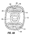
アンカー14は単独で用いてもよく、或いは少なくとも一つの付加的なアンカーと組み合わせて用いてもよい。図4Aに示すように、第1の実施例においては、二つ以上のこのようなアンカー14を別々の組織トンネル28に配置し、アンカー14のループ22は概略的に互いに整列している。この配列はアンカーを互いに独立させて、胃壁の運動に応じるアンカーの間の張力を最小にすることを可能とする。これに代えて、アンカーは相互接続してもよい。例えば図4Bに示す配置におけるように、複数のアンカーは、各アンカーの雄コネクタ24を他のアンカーの雌コネクタ26に接合させて配置される。この実施形態の一変形例においては、単独のアンカーを用いて、ここでは単独のループ(ループ22と同様)がこれに接続された少なくとも一つのファスナー20と共に与えられている。これらの後者の実施形態の何れかにおいて、自由に動く要素をループに設けてファスナー間の張力を最小化することができる。例えば図4Cに示すようにループ22aは、胃壁の運動に応じて一方のアンカーに対して摺動する嵌め合い部品から形成してもよい。
図4Dは他の代替的なアンカー14bを示し、ここではアンカー14bは、コネクタ24b,26bのような嵌め合い要素を有する可撓な細長いバンドから形成されている。このアンカー14bは、図示のようにバンドの一部がループ22bをなすように二つ以上の組織トンネル28を通じてバンドの一端を送ることによりインプラントされる。ループを形成するバンドの区画は図4Dに示すようにアンカーの上部に置いてもよく、絡み合わせてもよい。
FIG. 4D shows another alternative anchor 14b, where the anchor 14b is formed from a flexible elongated band having mating elements such as
再度図2を参照すると、インプラント12はアンカー14のループ22内にしっかりと保持されるように寸法付けられている。一つの実施形態によれば、インプラント12は、口側区画32と反口側区画34との間に位置する比較的に狭いウェスト区画30を含む。この配置によれば、図10E乃至図10Fに関連して説明したように、アンカー14のループ22はウェスト区画30に係合できるので、インプラント12を胃内に保持する。
Referring again to FIG. 2, the
図2及び5Aを参照すると、インプラント12は、口側開口136及び反口側開口138を囲んでリング38により包囲された口側リング36を含むことが好ましい。ウェスト区画30はリング36,38と同様なリングを含んでもよい。
With reference to FIGS. 2 and 5A, the
通路40は開口136,138の間で終端する。通路40は、以下のインプラントの節で詳述するように内視鏡その他の機器によりアクセスできる。インプラント12は中空にしてもよく、この場合、通路40はインプラントの中空内室と連続的にしてもよい。これに代えて、インプラントを環状にして、通路が環状形状における中央開口を形成するようにしてもよい(図6参照)。
インプラントは好ましくは胃内の使用に適する可撓性自己膨張性材料からなる。これは例えば、ポリエステル(例えばDacron(商標)ポリエステル)、ePTFEファブリック(例えばGoreTex商標ファブリックその他)、ウレタン(例えばChronoFlex(商標)ポリウレタン、ナイロンファブリック、シリコン、他のポリメリック材料、及び生体内吸収性材料(例えばPLLA、PGA、PCL、ポリ−アミヒドリドその他)を含む。図5Aに示すように、インプラント12はフレーム42(例えば、メッシュ、ストラット要素44及び/又は他の特徴から形成してもよい)を含んでもよい。このフレームはニチノール又は形状記憶ポリマーを用いて製作して、インプラントの自己膨張を促進することが好ましい。フレーム42には、Dacron(商標)ポリエステル、シリコン、ウレタンその他の材料から形成された被覆又はコーティングを設けてもよく、或いは被覆又はコーティングを設けなくてもよい。インプラント材料はインプラント12を流線型姿勢へ操作することを可能とするように充分に可撓にしてあり、これには例えば図5Bに示すように口側区画32と反口側区画34との間に張力を加えるか、或いはインプラントを径方向内側へ圧縮する。ウェスト30及びリング36,38は、それぞれ小孔31,37,39を含んでもよく、これはワイヤー、縫合、又はインプラント12をインプラントツールへ固定するのに用いる他の要素を収容する。
The implant is preferably made of a flexible self-expanding material suitable for use in the stomach. This includes, for example, polyester (eg Dacron ™ polyester), ePTFE fabric (eg GoreTex ™ fabric etc.), urethane (eg ChronoFlex ™ polyurethane, nylon fabric, silicone, other polymeric materials, and bioabsorbable materials ( For example, PLLA, PGA, PCL, poly-amihydride, etc. As shown in Figure 5A, the
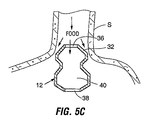
インプラント12の形状及び寸法は患者の摂食を少なくとも一つの方式で制限することにより減量を促進するように選択されている。例えば、図5Cを参照すると、インプラント12は、口側区画32が胃食道接合領域の周囲壁に近接して位置するときに、極く少量の食物がインプラント12の周りを通過するように輪郭付けされており、その通路40の寸法は、この通路40を一度に通過できる食物の量を制限する。従って、デバイスの制限及び閉塞特性は食道から胃への食物の通過を遅らせて、患者の食物大量摂食を防止する。様々な実施形態において、通路40の寸法は患者に要求される制限流量に基づいて選択できる。他の実施形態においては、通路40は密閉して非常に狭くするか、或いはインプラントがないときは、最終的には全ての摂取食物がインプラントの外周の周りの限られた空間の周りを流れるようにする。
The shape and dimensions of the
インプラントは、胃粘膜表面に接触する可能性のある領域に、軟らかくて組織を傷つけない縁をもたせることにより、組織の炎症を防ぐようにすることが好ましい。一つの代替的な実施の形態では、インプラントの外側プロファイルを球形又は半球形として、胃の運動中にデバイスが胃表面上を転動できるようにしてもよい。 The implant is preferably designed to prevent tissue irritation by providing a soft, non-injuring rim in areas that may contact the gastric mucosal surface. In one alternative embodiment, the outer profile of the implant may be spherical or hemispherical to allow the device to roll over the stomach surface during stomach movement.
図6に示す代替的インプラント12aにおいて、口側区画32aの表面は実質的に平坦である。反口側区画34aは図示のように湾曲させてもよく、或いは平坦にしてもよい。
In the
図7はインプラント12bの代替的実施例を示し、これは食道から胃への食物の流れを制限する代替例に加えて、またはそれに代えて、空間占有体として機能する。図7の実施例において、反口側区画34bは胃内の空間を充分に占有する程度に大きいので、満腹感を形成し、及び/又は胃の容量を低減させる。或る実施形態では、インプラント12bは約200乃至700ccの範囲の拡張容積を有して、胃を部分的に満たすのに充分なものとすることにより、患者に満腹感を感じさせて食物摂取を制限してもよい。インプラント12bは膨らませるようにして、膨張ポート46又は自己封止材料の領域を含めてもよく、これらはインプラントを配置した後に胃へ導かれる膨張チューブに係合する。
FIG. 7 shows an alternative embodiment of the
図7の実施形態は胃内の様々な位置に配置することができる。例えば、これを胃食道接合領域又は基底部に配置して、ここで空間を占めるように働かせて、有効胃容積を低減させてもよいが、上述の実施例で説明したように、食物が食道から胃へ降下する速度を制限するようにも働く。代替的に、これは洞A又は幽門P(図1A)内に配置して、有効胃容積を低減させ、及び/又は胃から腸への食物の排出を遅らせてもよい。 The embodiment of FIG. 7 can be placed at various locations within the stomach. For example, it may be placed in the gastroesophageal junction region or the base and act to occupy space here to reduce the effective gastric volume, but as described in the above examples, the food is esophagus. It also works to limit the rate of descent from the stomach to the stomach. Alternatively, it may be placed in sinus A or pylorus P (FIG. 1A) to reduce the effective stomach volume and / or delay the elimination of food from the stomach to the intestine.
再び図2を参照すると、図2のインプラントのための移植ツール16は外側シャフト15、中間シャフト17及び内側シャフト19を含む。外側シャフト15はインプラントの口側区画32を受け入れるように構成されており、シャフト15上の口側リング36の着座を促進するように、拡張マウント21を含めてもよい。同様に、内側シャフトはインプラント12の反口側区画34を受け入れるマウント23を有してもよく、中間シャフト17はインプラント12のウェスト区画30を収容するマウント25を含んでもよい。シャフト15,17,19は相互に入れ子式に摺動する。従ってシャフトマウント21,23,25を互いに対して拡げる拡張位置へ移動して、インプラントを図5Bに示す流線型姿勢へ延伸させる。同様に、シャフトはマウント21,23,25の間の間隙を閉止するように調整して、インプラントにその本来の姿勢をとらせるようにしてもよい。
Referring again to FIG. 2, the
シャフトの退縮は移植ツールのハンドル上の解除タブ43a,43bを用いて起動される。例えば、移植ツール16にはスプリング装填ラッチ(図示せず)を持たせてもよく、これはツールを拡張位置に保持し、且つ解除タブ43a,43bを係合解除させる。従って、例えば解除タブ43aの押し下げは外側シャフト15に関連するラッチを解除するので、外側シャフトを中間シャフト17に対して遠位端へ摺動させる。同様に、解除タブ43bの起動は内側シャフト19に関連するラッチを係合解除するので、内側シャフトを中間シャフトに対して基端側へ摺動させる。この実施形態においては、ラッチの解除の際のシャフトの移動は、スプリング偏倚としてもよく、又は手動としてもよい。
Shaft retraction is activated using
小さな孔27a,b,cをシャフト15,17,19の各々に形成して、ワイヤー、縫合、或いはインプラント12を移植ツール16へ固定するのに用いられる他の要素を受け入れるようにしてもよい。
代替的な移植ツールはインプラントを所望の場所へ送達させる他の機構によっている。例えば、代替的なツールはインプラントの部分を把持し、且つインプラントが正しい位置にあるときにインプラントを解除する退縮要素(例えば、リング、又は図11Aに示すループ84,86などのループ)を含んでもよい。代替的な実施の形態は専らインプラントを身体内で拡張させるインプラントの形状記憶特性によっている。
Alternative implantation tools rely on other mechanisms to deliver the implant to the desired location. For example, an alternative tool may include a retracting element (eg, a ring or loop such as
アンカー移植
アンカー14を移植する例示的な方法について以下に説明する。
Anchor Implantation An exemplary method for implanting
好ましい方法においては、胃壁に解剖学的構造を与えるように組織トンネル28/28a(図3A−3C)を形成し、これにアンカー14を結合してもよい。このトンネルは腹腔鏡、内視鏡、及び/又は外科的アプローチを用いて形成することができる。組織/トンネルを形成する様々な処置は出願人の先願であるWO2005/037152号(発明の名称”Devices and Methods for Retaining a Gastro−Esophageal Implant”、2202年4月25日発行)に説明されており、これは本願と共に所有されて本明細書に参照により組み込まれている。
In a preferred method,
この先願に説明したように、組織トンネルは、組織の区画を把持して、組織を併せて器械吻合して組織構造を形成することにより作成した組織襞を用いて形成される。このような構造は、組織により境界を付けられた内部空間を有するという意味でトンネル状であり、開口が位置しており、アンカー又は医療用デバイスの他の部分が一方の開口を通じてトンネルの内部空間を通り他方の開口から出るようにしてある。トンネルの内壁は互いに接触させ、シャツの中の空間が潰れるのと同様な方式で内部空間が潰れるようにおいてもよい。他の実施形態においては、トンネルはより中空な形状を保持してもよい。 As described in this prior application, a tissue tunnel is formed using a tissue fold created by grasping a tissue section and combining the tissues together to form a tissue structure. Such a structure is tunnel-like in the sense that it has an internal space bounded by tissue, the opening is located, and the anchor or other part of the medical device is passed through one opening through the internal space of the tunnel Through the other opening. The inner walls of the tunnel may be brought into contact with each other so that the interior space is crushed in the same manner as the space in the shirt is crushed. In other embodiments, the tunnel may retain a more hollow shape.
このような処置の幾つかは部分的には胃の外面の漿膜組織内層の粘着に依存している。漿膜組織層は互いに同格に保持された際に比較的に強力な結合を形成するように粘着することが見出されている。 Some of these procedures depend in part on the adhesion of the serosal tissue lining on the outer surface of the stomach. Serosa tissue layers have been found to adhere to form a relatively strong bond when held together in the same order.
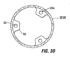
例えば、組織トンネルは図3A及び3Bに示すトンネル28と同様としもよく、或いはこれに代えて、漿膜組織襞92に孔90を形成することにより作成された図3C及び図3Dに示す形式のトンネル28aとしてもよい。何れかの形式の組織トンネルを形成する方法は、漿膜組織表面が同格に保持された際に強力な粘着が形成される利点をなす方式で実行してもよい。本明細書で詳述しない他の方法も本発明の要旨から逸脱することなく用いられる。
For example, the tissue tunnel may be similar to the
図8A乃至図8Fは例えば図3A及び図3Bに示す形式の組織トンネル(組織ポケットとも称する)を形成する一つの方法を図解する。 8A-8F illustrate one method of forming a tissue tunnel (also referred to as a tissue pocket) of the type shown, for example, in FIGS. 3A and 3B.
トンネルの向きは使用される特定の形式のアンカー/インプラント構成を最もよく収容するように選択される。例えば、トンネルは図8Fに示すように口側−反口側向きを有してもよく、或いは図3A及び図4Aにおけるように、より横向きでもよい。 The tunnel orientation is selected to best accommodate the particular type of anchor / implant configuration used. For example, the tunnel may have a mouth-to-mouth side orientation as shown in FIG. 8F, or may be more laterally oriented as in FIGS. 3A and 4A.
図8Aを参照すると、ロッド48を胃の外面上に配置し、縫合糸50をロッド48へ取り付けて、胃壁に挿通する。縫合糸50は内視鏡把持装置(図示せず)を用いて内側へ引いて、図8Cに示す形式の組織の区画52で「テント」を張るようにする。所望とあれば、この方法は図8Bに示したようなロッド48を使わずに実行してもよく、その場合には一対の縫合糸50aを胃内室から胃壁を通じて挿通させて胃内室へ戻し、次いで内視鏡把持装置54を用いて内側へ引いて、点線で示すように組織でテントを張るようにする。
Referring to FIG. 8A, a
次に、ステープラー又は縫合糸のライン56を胃の粘膜側からテント状組織を横断して施して、図8Dに示すように胃の外面上に閉止ポケット58を形成する。ロッド48(用いているとすれば)はポケット58内へ入れてある。ステープル留め/縫合は、食道を通じて胃へ挿通された内視鏡ステープラー60aを用いて実行してもよく、或いは外科的ガストロノミー部位を通じて胃へ導入された腹腔鏡ステープラー60bを用いてもよく、それらの何れも図8Cに示してある。ステープラー/縫合デバイスは好ましくは縫合/ステープルライン56を形成する特性を有し、これは患者に漿膜組織を共に封止して、完全な漿膜粘着に先立って胃の漏洩を防ぐのに充分であるが、ステープル留めされた組織の治癒を促進するように良好な血液流を確実にするものである。例えば、通常のステープラーは、補充用ステープルを取り除いたステープルカートリッジを持つように修正して、この目的を達成できるであろう。
A stapler or
カラー62は縫合/ステープリングに先立って図8Cに示すようにテント状組織52の周囲に配置して、組織壁に張力を与えて、縫合又はステープリングを促進してもよい。
縫合ライン56は図8Eに示すように組織の複数の漿膜層を併せて保持することにより、互いにポケット58を保持する。ポケットの端部64を切除して、包囲ポケット58を胃内室へ開口する端部を有する組織ポケット又はトンネル28へ曲げる。ロッド48を用いているならば、これをトンネル28から取り除く。組織は好ましくはトンネルを維持する粘着を形成するように互いに治癒する。
組織トンネル28は漿膜組織から形成されているので、トンネル28の内側をステント状デバイス68又は他の実施形態においてはライナーで覆うことは望ましいことであり、これは補強と酸性胃環境からの漿膜表面の保護との双方を与える。上述した実施例の多くは対向する組織層の間の組織粘着の形成によっている。ライナーは組織内成長を促進する足場としても働き、及び/又は形成される粘着を補強する役割も果たす。
Since the
この処置は胃内へ所望の和のアンカーを支持するのに必要な多くのトンネルを形成するように繰り返される。時間がたてば、同格に保持された組織の領域は身体の物理的又は生物学的応答(例えば繊維組織又は瘢痕組織の形成、新たな組織の成長、若しくは生長、治癒、対向する組織層の一体的結合)に起因して互いに粘着する。本願において用語「粘着」は何らかの物理的又は生物学的応答(上記に列挙したものを含むが、それに限定されるものではない)の結果としての対向組織層の粘着を意味するものとして用いる。 This procedure is repeated to form as many tunnels as necessary to support the desired sum of anchors in the stomach. Over time, a region of tissue that is held to equality is the body's physical or biological response (e.g., the formation of fibrous or scar tissue, the growth of new tissue, or the growth, healing, of opposing tissue layers). Adhere to each other due to integral bonding). As used herein, the term “adhesion” is used to mean adhesion of the opposing tissue layer as a result of any physical or biological response, including but not limited to those listed above.
図3C及び図3Dに示す形式の組織トンネル28aを形成するためには、漿膜襞92を形成する。更に詳しくは、胃内室内の組織を互いに挟んで胃外面へ漿膜を引き出して互いに接触させることにより、折り畳まれた組織若しくは襞92を形成する。孔90を襞92に形成し、ステープル94又は縫合糸その他を孔90の周りに取り付けて、漿膜粘着が形成されるまで組織を互いに挟まれた状態に保つ。図3Dに示すように複数の襞92を形成してもよい。
To form a
トンネル28(又は28a)が形成されると、一つ又は複数のアンカー14をトンネルへ接合できる。好ましい実施の形態では、トンネルが治癒するまでそのままにしてから、アンカー14をトンネルへ結合してインプラント12を位置させる後続の処置が実行される。しかしながら、所望とあれば、トンネルを形成する同一処置の間にアンカーを移植して、インプラントはトンネルが治癒後のその後の処置で配置してもよい。当然に、トンネル形成、アンカー取り付け、及びインプラント配置は三つの個別の処置で実行してもよい。
Once the tunnel 28 (or 28a) is formed, one or
アンカー14を移植するためには、好ましくは内視鏡的可視化の下に、各々のアンカーを食道を挿通して胃へ通す。アンカー14及びそれに関連する器具は食道内に位置するシースへ通して下行させ、周辺組織を保護する。アンカーのファスナー20の一部は組織トンネル28に挿通させて、コネクタ24,26を係合させて、図4Aに示すように、ファスナー20をループにする。この目的のためには、内視鏡把持装置その他の適切な内視鏡器具を用いることができる。第1の実施例によれば、第2のアンカーは図示のように第2の組織トンネルへ接続される。ここでは、好ましくはアンカー14のループ22を重ね合わせてインプラント12を収容する準備をする。
To implant the
図9A及び図9Bはアンカー14dを移植する代替的な方法を図解する。この方法によれば、アンカー14dは、胃壁に形成された組織襞28dへ取り付けられる。襞を形成する様々な方法がWO2005/037152号(発明の名称”Devices and Methods for Retaining a Gastro−Esophageal Implant” 2002年4月25日発行)に説明されている。漿膜襞を形成する一つの方法によれば、胃内室内の組織を(例えば内視鏡把持装置を用いて)併せて挟み、胃の外側で漿膜層を挟んで互いに接触させることにより、図示のように折り畳まれた組織タブが形成される。漿膜組織層の間に補強パッチ9を配置してもよい。このパッチは組織内成長を促進する足場として働き、及び/又は形成される粘着を補強する役割を果たす。縫合糸11(これは生体吸収性とすることができる)、綿撒糸13、tバーその他の締結手段を用いて、少なくとも粘着が組織層を互いに結合するまで、複数の組織層を併せて保持する。これらのファスナーは図示のようにアンカー14dを襞へ取り付けるのに用いられるが、代替的な方法においては、襞が治癒した後にア縫合糸、ステープルその他のファスナーを用いてアンカー14dを襞28dへ接合する。
9A and 9B illustrate an alternative method of implanting
最終的には、粘着は組織層の間(及び/又はパッチのすき間を通じて)に形成され、組織層の間の接合を補強するのに役立つ。 Ultimately, an adhesive is formed between the tissue layers (and / or through the gaps in the patch) to help reinforce the bond between the tissue layers.
パッチは、合成又は非合成メッシュ、多孔性材料、溝付き材料、或いは、その内部を通じて粘着が形成されるか又はその上で組織が成長する任意の材料とすることができる。例としては、ポリプロピレン、Goretex又はDacronの商標名で販売される材料、或いはWilson Cook Medical.Incにより販売されるSurgisis材料のような組織移植材料があるが、これらに限定されるものではない。これらの材料は生物製剤のように組織内成長を促進する物質で処理してもよい。 The patch can be a synthetic or non-synthetic mesh, a porous material, a grooved material, or any material on which an adhesive is formed or tissue grows. Examples include materials sold under the trade names of polypropylene, Goretex or Dacron, or Wilson Cook Medical. There are, but are not limited to, tissue transplant materials such as Surgisis materials sold by Inc. These materials may be treated with substances that promote tissue ingrowth, such as biologics.
インプラントの位置決め
図10Aは移植の準備にインプラント12をツール16へ取り付ける一つの方法を図解する。この図においては、インプラント壁を透明にして示してあり、口側及び反口側リング36,38並びにウェストリング30が見えるようにしてある。好ましい方法においては、インプラントを三つの取り付け点でツールへ取り付け、その三つの取り付け点は口側リング、反口側リング、及びウェスト区画におさまる。代替的な方法においては、インプラントを異なる場所、例えばデバイスの口側端部又は反口側端部のみ、あるいは何れかの場所へ取り付けてもよい。
Implant Positioning FIG. 10A illustrates one method of attaching the
図10Aの方法に従ってインプラントを取り付けるためには、第1の保持要素、例えばニチノールワイヤー29aをツールの開口基端における開口へ導入して、内側シャフト19の内腔を通じて末端へ通す。ワイヤーの末端を複数の孔27cのうちの最遠位の一つを通じて延伸させ、反口側リング38における開口39に通して、内側シャフトの内腔へ戻すように挿入して、ツール16の基端へ戻して、印を付けて、タブ41cにより併せて保持してもよい。ワイヤー29cの二つの端部はツールの外側に保持される。同様に、第2のニチノールワイヤー29bは内側シャフト19と中間シャフト17との間の環状空間を通して下行させ、開口27bの一つを通じて中間シャフトから出して、インプラントのウェストリング30における開口31へ通し、複数の開口27bのうち最近位の一つを介して環状空間へ戻す。ワイヤー29bの端部はタブ41bにより保持される。この処理はインプラントの口側端部にて口側リング36をニチノールワイヤー29aを用いて取り付けるように繰り返す。シャフト15,17,19の相対位置はインプラント12を延伸姿勢に配置して、所定位置に係止するように調整する。
To install the implant according to the method of FIG. 10A, a first retention element, such as
図10Bを参照すると、インプラント12がインプラントツール16上に組立てられると、ツール16は、内視鏡18をツールの内側シャフト19の中央内腔を通じて摺動させることにより、内視鏡18上に位置する。次いで、内視鏡の末端を経口で食道へ通し、移植に先立ってアンカー14のループ22へ通す。内視鏡は図10Cに示すように反り返っており、施術者に内視鏡が両方のループを通過したことを視覚的に確認させる。
Referring to FIG. 10B, once the
図10Dを参照すると、インプラントツール16は、インプラント12のウェスト30がループ22に隣接するまで内視鏡上を前進する。インプラントのウェストは識別マーカーにより印を付けて、この処置のステップを単純化するようにしてもよい。ウェスト30が適切に位置したならば、解除タブ43aを押し下げてインプラントツール16の外側シャフト15を末端方向へ摺動させて、口側リング36をウェスト30に近接するように移動させて、図10Eに示すようにインプラントの口側区画32を拡張させる。インプラントの拡張された口側部分が適切な位置にあることが視覚的に確認されたならば、ワイヤー29aを引き抜いて、口側リング36をインプラントツール16から外す。
Referring to FIG. 10D, the
次に図10Fを参照すると、解除タブ43bを起動して、内側シャフト19を基端方向へ引き出して、反口側リング38ウェスト30に近接させて、インプラントの反口側部分34を拡張させる。適切な展開を視覚的に確認して、ワイヤー29b及び29cを引き抜いて、インプラント12をツール16から取り外す。
Referring now to FIG. 10F, the
摘出
図11A及び図11Bはインプラント12を摘出する方法の一例を図解する。図11A及び図11Bの方法によれば、摘出は摘出ツール72を用いて実行され、これはシース74と、このシース74内に入れ子式に配置された中空ロッド76とからなる。
Extraction FIGS. 11A and 11B illustrate an example of a method of extracting the
シース74は小さな側方内腔78を有する。末端にフック80を有する細長いワイヤーは側部内腔78を通じて延伸自在であり、フック80をシース74の末端から展開させることができる。
The
先ず、摘出ツール72を中空ロッド76と共に配置してシース74へ完全に引き抜くが、内視鏡18はシース74の末端から末端方向へ延在する。ツール72を食道へ導入して、シース74をインプラント12の基端に位置させる。内視鏡18をインプラント12を通じて前進させて、図11Aに示すように反り返らせて、処置を可視化できるようにする。
First, the
次いでフック80をシース74を通じて前進させて、回収ループ84をインプラント12の口側部分に引っ掛けるように操作する。これに代えて、フック80を用いてインプラントの口側リング36(図2)を把持してもよい。インプラントの口側部分が係合したならば、中空ロッド76を前進させて、フック82にインプラント12の反口側端部上で回収ループ86を捕捉させる(或いは、反口側リング38を捕捉させる)。中空ロッド76及びシース74を反対方向へ移動させ、図11Bに示すようにインプラント12を延伸させて、インプラントを延伸姿勢に保持しながら、中空ロッド76及びシース74を同時に胃から(内視鏡18に沿って)引き出す。インプラント12が外植されたならば、図11Cに示すようにアンカー14のみが所定位置にとどまる。
The
代替的形態
図12は代替的なアンカー14eを示し、これはインプラントを支持するのに用いられる。アンカー14eは胃−食道接合に膜状構造体を形成するように配置された単独の部品又は複数の部品とすることができる。他のアンカーの実施形態で説明したように、アンカー14eは好ましくは組織トンネル28に連結されているが、これに代えて、図9A及び図9Bに関連して説明したように、漿膜襞に結合してもよく、又は他の手法で組織へ取り付けてもよい。
Alternative Form FIG. 12 shows an
図13を参照すると、アンカー14eは他の実施の形態に関連して説明したように、インプラント12eを収容するループ22eを有してもよい。インプラント12eは図2のインプラント12のように中央ウェスト区画により規定された砂時計状にくびれた形状を有してもよく、図13に示すようにテーパー状にしてもよい。図14を参照すると、アンカー14eは、インプラント12fの胃腸器官への更なる下降を単純に防止することにより、インプラント12fを支持するために用いてもよい。例えばインプラント12fは空間占有バルーンの形態を採ってもよく、これはアンカー14eに対する物理的な取り付け又は接続はされない。
Referring to FIG. 13, the
アンカー14eの移植は上述した技法を用いて達成できる。インプラント12fは、膨張チューブをインプラント12f内の膨張ポートへ接続して、インプラント12fを食道内に位置するシースを通して下降させることにより、配置することができる。インプラントが胃の中へ入ったら、膨張チューブを用いてインプラント12fを膨張させて、次いで膨張チューブをインプラントから取り外して身体から引き出す。
Implantation of the
インプラント12eは移植の欄で説明したのと同様な手順を用いて移植してもよい。 The implant 12e may be transplanted using a procedure similar to that described in the transplantation section.
様々な構成要素及び方法を本明細書に説明した。これらの実施例は例示として与えられたものであって、本発明の目的を限定することを意図するものではない。当業者には本発明の要旨と目的を逸脱することなく、形式的にも詳細にも様々な変更をなせることが明らかである。これは、後に発展するであろう関連技術の範疇にある技術及び技術用語の観点では特に明らかである。 Various components and methods have been described herein. These examples are given by way of illustration and are not intended to limit the purpose of the present invention. It will be apparent to those skilled in the art that various changes can be made in form and detail without departing from the spirit and scope of the invention. This is particularly evident in terms of technology and terminology within the related art that will develop later.
上述した実施例の様々な特徴は、多数の付加的な実施態様をなすための幾多の手法と組み合わせ得ることに留意されたい。また、様々な材料、寸法、形状、移植位置等について、開示された実施例を用いて説明したが、それらの開示事項以外のものも本発明の主旨を越えることなく利用できる。例えば、保持方法及びデバイスは胃食道系内の使用に限定されるものではなく、体内の他の場所に位置するインプラントのために用いてもよい。 It should be noted that the various features of the examples described above can be combined with a number of approaches to make a number of additional embodiments. Moreover, although various materials, dimensions, shapes, implantation positions, and the like have been described using the disclosed embodiments, things other than those disclosed matters can be used without exceeding the gist of the present invention. For example, the retention methods and devices are not limited to use within the gastroesophageal system and may be used for implants located elsewhere in the body.
上記に参照した全ての特許、特許出願及び公報は参照により本明細書に組み込まれている。 All patents, patent applications and publications referred to above are hereby incorporated by reference.
Claims (13)
口腔内で胃へアクセスする送達デバイスと、
口側の区画と、反口側の区画とを有し、これら口側の区画と反口側の区画とは、これら口側の区画及び反口側の区画よりも小さい断面を有するウェストにより区画されている制限インプラントとを備え、
二つの前記区画のうちの少なくとも一方が、収縮状態から膨張姿勢へ膨張可能であり、前記制限インプラントが、胃壁に取り付けられたループを通じて膨張したときに、前記制限インプラントが前記胃壁へ留置されるインプラントシステム。 An implant system,
A delivery device for accessing the stomach in the oral cavity;
It has a mouth side compartment and a counter mouth side compartment, and the mouth side compartment and the counter mouth side compartment are defined by a waist having a smaller cross section than the mouth side compartment and the counter mouth side compartment. A restriction implant that is
At least one of the two said compartments, an expandable from a contracted state to expanded position, said limit implant, when expanded through a loop attached to the stomach wall, the restriction implant is placed into the stomach wall Implant system.
Applications Claiming Priority (3)
| Application Number | Priority Date | Filing Date | Title |
|---|---|---|---|
| US68363505P | 2005-05-23 | 2005-05-23 | |
| US60/683,635 | 2005-05-23 | ||
| PCT/US2006/019727 WO2006127593A2 (en) | 2005-05-23 | 2006-05-23 | Restrictive and/or obstructive implant system for inducing weight loss |
Publications (3)
| Publication Number | Publication Date |
|---|---|
| JP2008541854A JP2008541854A (en) | 2008-11-27 |
| JP2008541854A5 JP2008541854A5 (en) | 2009-07-09 |
| JP5269589B2 true JP5269589B2 (en) | 2013-08-21 |
Family
ID=37452686
Family Applications (1)
| Application Number | Title | Priority Date | Filing Date |
|---|---|---|---|
| JP2008513585A Expired - Fee Related JP5269589B2 (en) | 2005-05-23 | 2006-05-23 | Restricted and / or occluded implant system for promoting weight loss |
Country Status (5)
| Country | Link |
|---|---|
| EP (1) | EP1883370B1 (en) |
| JP (1) | JP5269589B2 (en) |
| AT (1) | ATE518497T1 (en) |
| ES (1) | ES2371035T3 (en) |
| WO (1) | WO2006127593A2 (en) |
Families Citing this family (26)
| Publication number | Priority date | Publication date | Assignee | Title |
|---|---|---|---|---|
| US7097665B2 (en) | 2003-01-16 | 2006-08-29 | Synecor, Llc | Positioning tools and methods for implanting medical devices |
| US6675809B2 (en) | 2001-08-27 | 2004-01-13 | Richard S. Stack | Satiation devices and methods |
| CN101810521B (en) | 2001-08-27 | 2015-05-13 | 辛尼科有限责任公司 | Satiation devices and methods |
| US8206456B2 (en) | 2003-10-10 | 2012-06-26 | Barosense, Inc. | Restrictive and/or obstructive implant system for inducing weight loss |
| US20050247320A1 (en) | 2003-10-10 | 2005-11-10 | Stack Richard S | Devices and methods for retaining a gastro-esophageal implant |
| US7717843B2 (en) | 2004-04-26 | 2010-05-18 | Barosense, Inc. | Restrictive and/or obstructive implant for inducing weight loss |
| US9055942B2 (en) | 2005-10-03 | 2015-06-16 | Boston Scienctific Scimed, Inc. | Endoscopic plication devices and methods |
| EP1965706A1 (en) * | 2005-11-11 | 2008-09-10 | Occlutech GmbH | Medical self-expandable occlusion device |
| ES2527923T3 (en) | 2006-09-02 | 2015-02-02 | Barosense, Inc. | Intestinal sleeves and associated deployment systems and methods |
| US9314361B2 (en) | 2006-09-15 | 2016-04-19 | Boston Scientific Scimed, Inc. | System and method for anchoring stomach implant |
| US20090030284A1 (en) | 2007-07-18 | 2009-01-29 | David Cole | Overtube introducer for use in endoscopic bariatric surgery |
| CN101827559B (en) | 2007-07-18 | 2013-05-29 | 压力感应器公司 | Endoscopic implant system |
| US8020741B2 (en) | 2008-03-18 | 2011-09-20 | Barosense, Inc. | Endoscopic stapling devices and methods |
| US8182442B2 (en) | 2008-04-09 | 2012-05-22 | Electrocore Llc | Pyloric valve devices and methods |
| WO2009126268A1 (en) | 2008-04-09 | 2009-10-15 | Endocore Llc | Pyloric valve |
| US7934631B2 (en) | 2008-11-10 | 2011-05-03 | Barosense, Inc. | Multi-fire stapling systems and methods for delivering arrays of staples |
| US9278019B2 (en) | 2009-04-03 | 2016-03-08 | Metamodix, Inc | Anchors and methods for intestinal bypass sleeves |
| US9173760B2 (en) | 2009-04-03 | 2015-11-03 | Metamodix, Inc. | Delivery devices and methods for gastrointestinal implants |
| US8702641B2 (en) | 2009-04-03 | 2014-04-22 | Metamodix, Inc. | Gastrointestinal prostheses having partial bypass configurations |
| US8211186B2 (en) | 2009-04-03 | 2012-07-03 | Metamodix, Inc. | Modular gastrointestinal prostheses |
| US8961539B2 (en) | 2009-05-04 | 2015-02-24 | Boston Scientific Scimed, Inc. | Endoscopic implant system and method |
| AU2010271294B2 (en) | 2009-07-10 | 2015-09-03 | Metamodix, Inc. | External anchoring configurations for modular gastrointestinal prostheses |
| US20120004677A1 (en) | 2010-05-21 | 2012-01-05 | Balbierz Daniel J | Tissue-acquisition and fastening devices and methods |
| WO2014113483A1 (en) | 2013-01-15 | 2014-07-24 | Metamodix, Inc. | System and method for affecting intestinal microbial flora |
| US9622897B1 (en) | 2016-03-03 | 2017-04-18 | Metamodix, Inc. | Pyloric anchors and methods for intestinal bypass sleeves |
| KR102473258B1 (en) | 2016-05-19 | 2022-12-01 | 메타모딕스, 인코포레이티드 | Pyloric Anchor Recovery Tools and Methods |
Family Cites Families (3)
| Publication number | Priority date | Publication date | Assignee | Title |
|---|---|---|---|---|
| JP4230915B2 (en) | 2001-12-21 | 2009-02-25 | シムチャ ミロ | Annuloplasty ring transplantation system |
| US6746460B2 (en) * | 2002-08-07 | 2004-06-08 | Satiety, Inc. | Intra-gastric fastening devices |
| US20050247320A1 (en) * | 2003-10-10 | 2005-11-10 | Stack Richard S | Devices and methods for retaining a gastro-esophageal implant |
-
2006
- 2006-05-23 AT AT06770834T patent/ATE518497T1/en not_active IP Right Cessation
- 2006-05-23 EP EP06770834A patent/EP1883370B1/en not_active Not-in-force
- 2006-05-23 WO PCT/US2006/019727 patent/WO2006127593A2/en active Application Filing
- 2006-05-23 ES ES06770834T patent/ES2371035T3/en active Active
- 2006-05-23 JP JP2008513585A patent/JP5269589B2/en not_active Expired - Fee Related
Also Published As
| Publication number | Publication date |
|---|---|
| ES2371035T3 (en) | 2011-12-26 |
| EP1883370B1 (en) | 2011-08-03 |
| JP2008541854A (en) | 2008-11-27 |
| EP1883370A2 (en) | 2008-02-06 |
| WO2006127593A3 (en) | 2007-06-14 |
| WO2006127593A2 (en) | 2006-11-30 |
| ATE518497T1 (en) | 2011-08-15 |
Similar Documents
| Publication | Publication Date | Title |
|---|---|---|
| JP5269589B2 (en) | Restricted and / or occluded implant system for promoting weight loss | |
| US10285836B2 (en) | Systems and methods related to gastro-esophageal implants | |
| US9839546B2 (en) | Apparatus and methods for treatment of morbid obesity | |
| US7837669B2 (en) | Devices and methods for endolumenal gastrointestinal bypass | |
| JP5252806B2 (en) | Device and method for holding a gastroesophageal implant | |
| US7846138B2 (en) | Cuff and sleeve system for gastrointestinal bypass | |
| US7037344B2 (en) | Apparatus and methods for treatment of morbid obesity | |
| US7214233B2 (en) | Methods and devices for maintaining a space occupying device in a relatively fixed location within a stomach | |
| EP1555970B1 (en) | Apparatus for treatment of morbid obesity | |
| US20040044353A1 (en) | Methods and devices for maintaining a space occupying device in a relatively fixed location within a stomach |
Legal Events
| Date | Code | Title | Description |
|---|---|---|---|
| A521 | Request for written amendment filed |
Free format text: JAPANESE INTERMEDIATE CODE: A523 Effective date: 20090525 |
|
| A621 | Written request for application examination |
Free format text: JAPANESE INTERMEDIATE CODE: A621 Effective date: 20090525 |
|
| A977 | Report on retrieval |
Free format text: JAPANESE INTERMEDIATE CODE: A971007 Effective date: 20111104 |
|
| A131 | Notification of reasons for refusal |
Free format text: JAPANESE INTERMEDIATE CODE: A131 Effective date: 20111108 |
|
| A601 | Written request for extension of time |
Free format text: JAPANESE INTERMEDIATE CODE: A601 Effective date: 20120208 |
|
| A602 | Written permission of extension of time |
Free format text: JAPANESE INTERMEDIATE CODE: A602 Effective date: 20120215 |
|
| A521 | Request for written amendment filed |
Free format text: JAPANESE INTERMEDIATE CODE: A523 Effective date: 20120302 |
|
| A131 | Notification of reasons for refusal |
Free format text: JAPANESE INTERMEDIATE CODE: A131 Effective date: 20120403 |
|
| A601 | Written request for extension of time |
Free format text: JAPANESE INTERMEDIATE CODE: A601 Effective date: 20120614 |
|
| A602 | Written permission of extension of time |
Free format text: JAPANESE INTERMEDIATE CODE: A602 Effective date: 20120625 |
|
| A601 | Written request for extension of time |
Free format text: JAPANESE INTERMEDIATE CODE: A601 Effective date: 20120801 |
|
| A602 | Written permission of extension of time |
Free format text: JAPANESE INTERMEDIATE CODE: A602 Effective date: 20120808 |
|
| A601 | Written request for extension of time |
Free format text: JAPANESE INTERMEDIATE CODE: A601 Effective date: 20120831 |
|
| A602 | Written permission of extension of time |
Free format text: JAPANESE INTERMEDIATE CODE: A602 Effective date: 20120907 |
|
| A521 | Request for written amendment filed |
Free format text: JAPANESE INTERMEDIATE CODE: A523 Effective date: 20121003 |
|
| TRDD | Decision of grant or rejection written | ||
| A01 | Written decision to grant a patent or to grant a registration (utility model) |
Free format text: JAPANESE INTERMEDIATE CODE: A01 Effective date: 20130409 |
|
| A61 | First payment of annual fees (during grant procedure) |
Free format text: JAPANESE INTERMEDIATE CODE: A61 Effective date: 20130508 |
|
| R150 | Certificate of patent or registration of utility model |
Free format text: JAPANESE INTERMEDIATE CODE: R150 Ref document number: 5269589 Country of ref document: JP Free format text: JAPANESE INTERMEDIATE CODE: R150 |
|
| R250 | Receipt of annual fees |
Free format text: JAPANESE INTERMEDIATE CODE: R250 |
|
| R250 | Receipt of annual fees |
Free format text: JAPANESE INTERMEDIATE CODE: R250 |
|
| R250 | Receipt of annual fees |
Free format text: JAPANESE INTERMEDIATE CODE: R250 |
|
| LAPS | Cancellation because of no payment of annual fees |