JP5268809B2 - curtain wall - Google Patents

curtain wall Download PDF

Info

Publication number
JP5268809B2
JP5268809B2 JP2009166885A JP2009166885A JP5268809B2 JP 5268809 B2 JP5268809 B2 JP 5268809B2 JP 2009166885 A JP2009166885 A JP 2009166885A JP 2009166885 A JP2009166885 A JP 2009166885A JP 5268809 B2 JP5268809 B2 JP 5268809B2
Authority
JP
Japan
Prior art keywords
waterproof block
waterproof
block
mullion
wall
Prior art date
Legal status (The legal status is an assumption and is not a legal conclusion. Google has not performed a legal analysis and makes no representation as to the accuracy of the status listed.)
Active
Application number
JP2009166885A
Other languages
Japanese (ja)
Other versions
JP2011021372A (en
Inventor
利幸 塚田
辰雄 安田
Current Assignee (The listed assignees may be inaccurate. Google has not performed a legal analysis and makes no representation or warranty as to the accuracy of the list.)
Sankyo Tateyama Inc
Original Assignee
Sankyo Tateyama Inc
Priority date (The priority date is an assumption and is not a legal conclusion. Google has not performed a legal analysis and makes no representation as to the accuracy of the date listed.)
Filing date
Publication date
Application filed by Sankyo Tateyama Inc filed Critical Sankyo Tateyama Inc
Priority to JP2009166885A priority Critical patent/JP5268809B2/en
Publication of JP2011021372A publication Critical patent/JP2011021372A/en
Application granted granted Critical
Publication of JP5268809B2 publication Critical patent/JP5268809B2/en
Active legal-status Critical Current
Anticipated expiration legal-status Critical

Links

Images

Abstract

<P>PROBLEM TO BE SOLVED: To provide a curtain wall having high waterproofing performance without using a wet sealing material in a connection part of a mullion and a transom. <P>SOLUTION: This curtain wall includes upper and lower mullions 1, 2 and right and left transoms 3. An indoor side face of the mullion on the upper side is downward extended from a lower end header and forms an extended wall part 11. The transom is fitted into a space surrounded by the mullion on the upper side, the extended wall part, and the mullion on the lower side from the right and left sides. The extended wall part opposes to an indoor side face 31 of the transom and has an upper mullion waterproof block 6. The mullion on the lower side has a lower mullion waterproof block 7 on an upper end header. The right and left transoms have transom waterproof blocks 8 on opposing headers, respectively. Both of the transom waterproof blocks have a depth face 81 and an indoor side face 82 being flush with the indoor side face of the transom which come into pressure-contact mutually, respectively. An outdoor side face 61 of the upper mullion waterproof block comes into pressure-contact with the indoor side faces of the transom waterproof block and the transom, and a lower face 62 of the upper mullion waterproof block comes into pressure-contact with an upper face 71 of the lower mullion waterproof block. <P>COPYRIGHT: (C)2011,JPO&amp;INPIT

Description

本発明は、上下の方立と左右の無目とを突き合わせる連結部を有するカーテンウォールに関する。   The present invention relates to a curtain wall having a connecting portion that abuts upper and lower vertical surfaces and left and right invisible eyes.

従来、カーテンウォールの方立と無目との連結部は、湿式のシール材でシールして防水していた。しかし、湿式のシール材は、シール材により外壁が汚れること、劣化しやすいこと、養生期間が必要でありまた雨天時には施工ができず作業性が悪いこと、シール目地がポケット状になり水がたまりやすいことなどが問題であった。そこで、特許文献1のカーテンウォールは、湿式のシール材を用いず、方立と無目のそれぞれの端部にシリコンスポンジゴムを配してあり、左右の無目に配したシリコンスポンジゴム同士が当接し、さらにその上下に方立に配したシリコンスポンジゴムが当接することで防水している(図10)。こうした防水用のゴムは成形品であるから管理がしやすく、シール材のように外壁を汚すこともない。また、耐久性、作業性も良好である。   Conventionally, the connecting portion of the curtain wall in the vertical direction and the invisible state has been waterproofed by sealing with a wet sealant. However, the wet seal material is contaminated by the seal material, easily deteriorates, requires a curing period, cannot be constructed in rainy weather, has poor workability, and the seal joint becomes pocket-shaped and collects water. The problem was that it was easy. Therefore, the curtain wall of Patent Document 1 does not use a wet sealing material, and silicon sponge rubber is arranged at each end of the vertical and invisible, and the left and right invisible silicone sponge rubbers are connected to each other. It is waterproofed by contact with silicon sponge rubber arranged vertically on the top and bottom (FIG. 10). Since such waterproof rubber is a molded product, it is easy to manage, and the outer wall is not soiled like a sealing material. Also, durability and workability are good.

特開2005−127097号公報JP 2005-127097 A

しかしながら、特許文献1のカーテンウォールにおいては、シリコンスポンジゴム同士の当接面が室外側から室内側まで連続しているから、当接面に水が浸入した場合、その水が室内側まで到達してしまうおそれがある。また、連結部周辺の水の流れについても考慮されていない。   However, in the curtain wall of Patent Document 1, since the contact surfaces of the silicon sponge rubbers are continuous from the outdoor side to the indoor side, when water enters the contact surface, the water reaches the indoor side. There is a risk that. Further, the flow of water around the connecting portion is not taken into consideration.

本発明は、上記事情を鑑みたものであり、方立と無目との連結部において、湿式のシール材を用いることなく、高い防水性を有するカーテンウォールを提供することを目的とする。   The present invention has been made in view of the above circumstances, and an object of the present invention is to provide a curtain wall having a high waterproof property without using a wet sealant at a connecting portion between a vertical and an invisible.

本発明のうち請求項1の発明は、上下の方立と左右の無目とを備え、上側の方立は、下端小口から室内側面が下方に延出して延出壁部を形成しており、上側の方立と、延出壁部と、下側の方立とで囲まれた空間に左右から無目が嵌め込んであり、延出壁部は、無目の室内側面に対向して上方立防水ブロックを有しており、下側の方立は、上端小口に下方立防水ブロックを有しており、左右の無目は、対向する小口にそれぞれ無目防水ブロックを有しており、両無目防水ブロックは、互いに圧接する見込面と、無目の室内側面と面一の室内側面を有しており、上方立防水ブロックの室外側面が無目防水ブロック及び無目の室内側面に圧接しており、上方立防水ブロックの下面が下方立防水ブロックの上面に圧接していることを特徴とする。   The invention according to claim 1 of the present invention is provided with upper and lower vertices and left and right blinds, and the upper pedestal has an interior wall surface extending downwardly from the lower end edge to form an extending wall portion. , The eyes are fitted from the left and right into the space surrounded by the upper side wall, the extended wall part, and the lower side wall, and the extended wall part faces the inner side surface of the eyeless room It has an upper standing waterproof block, the lower side stand has a lower standing waterproof block at the top edge, and the left and right eyes have an eyeless waterproof block at the opposite edge respectively. The both waterproof waterproof blocks have a prospective surface that is pressed against each other, an indoor side surface that is flush with the invisible indoor side surface, and the outdoor side surface of the upper standing waterproof block is the invisible waterproof block and the invisible indoor side surface. And the lower surface of the upper standing waterproof block is in pressure contact with the upper surface of the lower standing waterproof block.

本発明のうち請求項2の発明は、無目防水ブロックの上面は、無目の見込面に向けて下り勾配で傾斜していることを特徴とする。   The invention of claim 2 of the present invention is characterized in that the upper surface of the seamless waterproof block is inclined with a downward slope toward the expected surface of the seamless.

本発明のうち請求項3の発明は、下方立防水ブロックは、上下方向に貫通する排水部を有しており、方立は、略筒形で中空部を有しており、下方立防水ブロックの排水部が下側の方立の中空部と連通していることを特徴とする。   According to the invention of claim 3 of the present invention, the lower vertical waterproof block has a drainage portion penetrating in the vertical direction, the vertical is substantially cylindrical and has a hollow portion, and the lower vertical waterproof block The drainage part of this is connected to the lower vertical hollow part.

本発明のうち請求項4の発明は、下側の方立の室外側に押縁が設けてあり、下側の方立に設けた押縁の上端小口に押縁防水ブロックを有しており、押縁防水ブロックの上面が無目防水ブロックの下面に圧接していることを特徴とする。   According to the invention of claim 4 of the present invention, a pressing edge is provided on the outside of the lower vertical wall, and a pressing edge waterproof block is provided at the upper edge of the pressing edge provided on the lower vertical wall. The upper surface of the block is in pressure contact with the lower surface of the seamless waterproof block.

本発明のうち請求項5の発明は、上下左右に腕部が延びる十字形のブラケットを備え、上下の方立及び左右の無目は、ブラケットの各腕部に連結してあることを特徴とする。   The invention according to claim 5 of the present invention is characterized by comprising a cross-shaped bracket with arms extending vertically and horizontally, and the vertical and horizontal vertices being connected to each arm of the bracket. To do.

本発明のうち請求項1の発明によれば、上側の方立の延出壁部に無目の室内側面に対向して上方立防水ブロックが設けてあり、無目防水ブロックの室内側面が上方立防水ブロックの室外側面に圧接していることから、水が上方立防水ブロックより室内側に浸入するのを確実に防ぐことができる。また、無目の室内側面が上方立防水ブロックの室外側面に圧接していることから、方立に対する無目の水平方向の角度変位の許容範囲が拡大し、多少のズレが有る場合でも防水性を確保できる。   According to the first aspect of the present invention, the upper standing waterproof wall is provided on the upper vertical extending wall portion so as to oppose the seamless indoor side surface, and the indoor side surface of the seamless waterproof block is upward. Since it press-contacts to the outdoor side surface of a standing waterproof block, it can prevent reliably that water permeates into an indoor side from an upper standing waterproof block. In addition, since the invisible indoor side surface is in pressure contact with the outdoor side surface of the upper standing waterproof block, the allowable range of invisible horizontal angular displacement with respect to the vertical is expanded, and even if there is some deviation, it is waterproof Can be secured.

本発明のうち請求項2の発明によれば、無目防水ブロックの上面が傾斜しているので、水が連結部から左右方向に導かれる。また、方立及び無目に嵌め込まれたガラスパネルが層間変位した場合でも、上記の傾斜によりガラスパネルと無目防水ブロックとの衝突を回避できる。   According to invention of Claim 2 among this invention, since the upper surface of the seamless waterproof block inclines, water is guide | induced to the left-right direction from a connection part. Further, even when the glass panel fitted in a vertical or invisible state is displaced between layers, the above-described inclination can avoid a collision between the glass panel and the invisible waterproof block.

本発明のうち請求項3の発明によれば、無目防水ブロックの互いに圧接する見込面に水が浸透した場合でも、その水は下方立防水ブロックの排水部から下側の方立の中空部へと導かれ、当該連結部の一段下の連結部に到達し、無目防水ブロックにより左右方向に導かれる。   According to the invention of claim 3 of the present invention, even when water permeates the prospective surfaces of the seamless waterproof block that are pressed against each other, the water is separated from the drainage portion of the lower vertical waterproof block to the lower vertical hollow portion. To the connecting part one step below the connecting part and guided in the left-right direction by the seamless waterproof block.

本発明のうち請求項4の発明によれば、押縁に設けた押縁防水ブロックが無目防水ブロックに圧接しているので、押縁の上端部からの水の浸入を防ぐ。   According to the invention of claim 4 of the present invention, since the waterproof waterproof block provided on the pressing edge is in pressure contact with the seamless waterproof block, the intrusion of water from the upper end of the pressing edge is prevented.

本発明のうち請求項5の発明によれば、十字形のブラケットのそれぞれの腕部に上下の方立及び左右の無目を連結すればよいので、連結部における方立及び無目の位置決めが容易である。   According to the invention of the fifth aspect of the present invention, since the vertical and horizontal vertices may be connected to the respective arm portions of the cross-shaped bracket, the vertical and unaided positioning at the connecting portion can be achieved. Easy.

本発明のカーテンウォールの連結部の斜視図である。It is a perspective view of the connection part of the curtain wall of this invention. 連結部の組み立て途中の斜視図である。It is a perspective view in the middle of the assembly of a connection part. 連結部の組み立て途中の斜視図である。It is a perspective view in the middle of the assembly of a connection part. 連結部の組み立て後の外観の斜視図である。It is a perspective view of the external appearance after an assembly of a connection part. 図7のA−A線断面図であり、連結部の横断面図である。FIG. 8 is a cross-sectional view taken along line AA in FIG. 7, and is a cross-sectional view of the connecting portion. 図7のB−B線断面図であり、連結部の縦断面図である。FIG. 8 is a cross-sectional view taken along line B-B in FIG. 7, and is a vertical cross-sectional view of a connecting portion. カーテンウォールの正面図である。It is a front view of a curtain wall. 無目防水ブロックの詳細図である。It is a detailed view of a seamless waterproof block. ガラスパネルが層間変位した場合の説明図である。It is explanatory drawing when a glass panel carries out interlayer displacement.

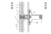
以下、本発明の実施の形態を図面に基づいて説明する。このカーテンウォールは、図7に示すように、格子状に組んだ方立1,2及び無目3にガラスパネルPを嵌め込んだもので、上側の方立1、下側の方立2及び左右の無目3を突き合わせる連結部Jを有する。そして図5に示すように、方立1は略四角筒形状で中空部12を有し、室外側には押縁4を取り付けるための取付溝13が形成してあり、室内側にはブラケット100をネジ止めするための溝状のネジ止め部14が形成してある。押縁4は、断面が略T字形状で方立1の取付溝13に取り付けてあり、方立1と押縁4のそれぞれに設けたタイト材TによりガラスパネルPを挟み込んで固定してある。また図6に示すように、無目3は略四角筒形状で室外側に向けて下向きに傾斜した補強材32を有し、室外側に延出部33が形成してあり、室内側にはブラケット100をネジ止めするためのネジ止め部34が形成してある。押縁10は断面が略F字形状で、無目3の延出部33の先端部に形成した係合部36に係合して取り付けてあり、無目3と押縁10のそれぞれに設けたタイト材TによりガラスパネルPを挟み込んで固定してある。そして、ブラケット100はその室内側端において躯体Fにネジ止めしてある。   Hereinafter, embodiments of the present invention will be described with reference to the drawings. As shown in FIG. 7, this curtain wall is a glass panel P fitted into lattices 1, 2, and mesh 3, which are assembled in a lattice pattern. It has the connection part J which butt | matches the right and left invisible 3. As shown in FIG. 5, the vertical 1 has a substantially rectangular tube shape and has a hollow portion 12, an attachment groove 13 for attaching the pressing edge 4 is formed on the outdoor side, and a bracket 100 is provided on the indoor side. A groove-like screwing portion 14 for screwing is formed. The pressing edge 4 has a substantially T-shaped cross section and is attached to the mounting groove 13 of the vertical 1, and the glass panel P is sandwiched and fixed by a tight material T provided on each of the vertical 1 and the pressing edge 4. As shown in FIG. 6, the mesh 3 has a substantially rectangular tube shape and includes a reinforcing member 32 that is inclined downward toward the outdoor side. An extending portion 33 is formed on the outdoor side. A screwing portion 34 for screwing the bracket 100 is formed. The pressing edge 10 has a substantially F-shaped cross section and is engaged with and attached to an engaging portion 36 formed at the tip of the extending portion 33 of the seamless mesh 3. The glass panel P is sandwiched and fixed by the material T. The bracket 100 is screwed to the housing F at the indoor side end.

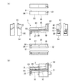
続いて、連結部Jの詳細について、組み立て後及び組み立て途中の斜視図である図1〜図4に基づいて説明する。ただし、これらの図において、タイト材及びガラスパネルについては省略した。この連結部Jにおいて、上側の方立1の下端小口からは室内側面が下方に延出して、延出壁部11を形成している。延出壁部11の室外側には、略平板形状の上方立防水ブロック6を接着して設けてある。一方、下側の方立2の上端小口には、略コ字形状の下方立防水ブロック7が、前側に開口する向きに設けてある。下方立防水ブロック7は、左右方向中央で二分割されており、下面には突出部(図示省略)を備え、この突出部を方立2の中空部22に差し込んである。そしてコ字形状の中央の欠損部分を上下に貫通する排水部72とし、排水部72は中空部22と連通している。さらに、左右の無目3の対向する小口には、それぞれ無目防水ブロック8が設けてある。無目防水ブロック8の形状は、図8(a)に示すものであり、前後方向に延びる胴部85と、胴部85の他方の無目3と対向する側に形成した見込面81と、胴部85の室内側に形成した室内側面82と、胴部85の室外側に形成した室外側面86と、室外側面86の下端の下面84と、胴部85の下側に形成したリブ87とを有し、胴部85とリブ87の間に溝部88が形成されている。また、胴部85の上面83は、見込面81側に向けて上向きに傾斜しており、見込面81の下端面89は、見込面81側に向けて下向きに傾斜している。このように形成した無目防水ブロック8は、図8(b)に示すように、無目3の補強材32及び延出部33を溝部88に挿入して無目3の小口に取り付けてある。この際、上面83は、見込面81側から、無目3の見込面である補強材32及び延出部33に向けて下り勾配で傾斜し、室内側面82は無目3の室内側面31と面一になり、室外側面86は無目3の延出部33の室外側面35と略面一になる。また、連結部J近傍において、無目3の室外側面には排水窓37を形成してあり、延出部33には室外側面35及び係合部36の一部を切り欠いた切欠部38が形成してある。さらに、無目3の押縁10には、室内側面と見込面のそれぞれに排水孔10a,10bが形成してある。また、下側の方立2に設けた押縁5の上端小口には、押縁防水ブロック9が設けてある。押縁防水ブロック9は、縦断面が台形で、下面には突出部(図示省略)を備え、この突出部を押縁5の上端に差し込んである。なお、各防水ブロックは、シリコンスポンジゴムからなる。   Then, the detail of the connection part J is demonstrated based on FIGS. 1-4 which are perspective views after an assembly and in the middle of an assembly. However, in these figures, the tight material and the glass panel are omitted. In this connecting portion J, the interior side surface extends downward from the lower end edge of the upper stand 1 to form an extended wall portion 11. On the outdoor side of the extending wall portion 11, a substantially flat upper waterproof block 6 is bonded and provided. On the other hand, an approximately U-shaped lower vertical waterproof block 7 is provided at the upper end edge of the lower stand 2 so as to open to the front side. The lower vertical waterproof block 7 is divided into two at the center in the left-right direction, and has a protruding portion (not shown) on the lower surface, and this protruding portion is inserted into the hollow portion 22 of the vertical 2. Then, the U-shaped central missing portion is used as a drainage portion 72 penetrating vertically, and the drainage portion 72 communicates with the hollow portion 22. Furthermore, the waterproof waterproof block 8 is provided in the opposite small opening of the left and right seamless 3 respectively. The shape of the seamless waterproof block 8 is as shown in FIG. 8A, and includes a trunk portion 85 extending in the front-rear direction, a prospective surface 81 formed on the side of the trunk portion 85 facing the other invisible 3, An indoor side surface 82 formed on the indoor side of the trunk portion 85, an outdoor side surface 86 formed on the outdoor side of the trunk portion 85, a lower surface 84 at the lower end of the outdoor side surface 86, and a rib 87 formed on the lower side of the trunk portion 85. A groove portion 88 is formed between the body portion 85 and the rib 87. Further, the upper surface 83 of the trunk portion 85 is inclined upward toward the expected surface 81 side, and the lower end surface 89 of the expected surface 81 is inclined downward toward the expected surface 81 side. As shown in FIG. 8B, the seamless waterproof block 8 formed in this way is attached to the small edge of the seamless 3 by inserting the reinforcing member 32 and the extending portion 33 of the seamless 3 into the groove 88. . At this time, the upper surface 83 is inclined downwardly from the prospective surface 81 side toward the reinforcing member 32 and the extending portion 33 that are the prospective surfaces of the seamless 3, and the indoor side surface 82 is connected to the indoor side surface 31 of the seamless 3. The outdoor side surface 86 is substantially flush with the outdoor side surface 35 of the extension portion 33 of the mesh 3. Further, in the vicinity of the connecting portion J, a drainage window 37 is formed on the seamless outdoor side surface, and the extended portion 33 has a cutout portion 38 in which a part of the outdoor side surface 35 and the engaging portion 36 are cut out. It is formed. Furthermore, drain holes 10a and 10b are formed in the seamless ledge 10 on the indoor side surface and the prospective surface, respectively. Further, a ledge waterproof block 9 is provided at the upper end edge of the ledge 5 provided on the lower side wall 2. The pressed-edge waterproof block 9 has a trapezoidal vertical cross section, and has a protruding portion (not shown) on the lower surface. The protruding portion is inserted into the upper end of the pressed edge 5. Each waterproof block is made of silicon sponge rubber.

そして、これらの方立1,2及び無目3を、ブラケット100により連結する。ブラケット100は十字形で、上下左右に延びる腕部101を有している。まず、下側の方立2を、ブラケット100の下側の腕部101にネジ止めする(図2の状態)。続いて、上側の方立1を、ブラケット100の上側の腕部101にネジ止めする(図3の状態)。この際、上方立防水ブロック6の下面62が、下方立防水ブロック7の上面71に圧接する。そしてこの状態では、上側の方立1、その延出壁部11及び下側の方立2が左右方向から見て略コ字形になっており、その開口部に左右の無目3が嵌るように、それぞれブラケット100の左右の腕部101にネジ止めする(図1の状態)。この際、両無目防水ブロック8の見込面81が互いに圧接し、また上方立防水ブロック6の室外側面61が無目防水ブロック8の室内側面82及び無目3の室内側面31に圧接する。また、下側の方立2の取付溝23に押縁5を取り付け、押縁5の押縁防水ブロック9の上面91が無目防水ブロック8の下面84に圧接する。さらに、上側の方立1の取付溝13及び左右の無目3の延出部33にそれぞれ押縁4,10を取り付け、上側の押縁4の下端が押縁防水ブロック9に圧接し、上下の押縁4,5及び左右の押縁10は面一となる。なお、上側の方立1の下端と左右の無目3との間及び上側の押縁4と左右の押縁10との間はシール材Sによりシールしてある(図4の状態)。   Then, these verticals 1 and 2 and the seamless 3 are connected by the bracket 100. The bracket 100 has a cross shape, and has an arm portion 101 extending vertically and horizontally. First, the lower stand 2 is screwed to the lower arm 101 of the bracket 100 (state shown in FIG. 2). Subsequently, the upper stand 1 is screwed to the upper arm 101 of the bracket 100 (state shown in FIG. 3). At this time, the lower surface 62 of the upper standing waterproof block 6 is in pressure contact with the upper surface 71 of the lower standing waterproof block 7. In this state, the upper stand 1, its extending wall portion 11 and the lower stand 2 are substantially U-shaped when viewed from the left-right direction, and the left and right invisible eyes 3 fit into the opening. Next, the left and right arms 101 of the bracket 100 are screwed to each other (state shown in FIG. 1). At this time, the prospective surfaces 81 of both the seamless waterproof blocks 8 are in pressure contact with each other, and the outdoor side surface 61 of the upper standing waterproof block 6 is in pressure contact with the indoor side surface 82 of the seamless waterproof block 8 and the indoor side surface 31 of the seamless 3. Further, the pressing edge 5 is attached to the mounting groove 23 of the lower vertical 2, and the upper surface 91 of the pressing edge waterproof block 9 of the pressing edge 5 is pressed against the lower surface 84 of the seamless waterproof block 8. Further, the pressing edges 4 and 10 are respectively attached to the mounting groove 13 of the upper stand 1 and the left and right extension parts 33, and the lower ends of the upper pressing edges 4 are in pressure contact with the pressing edge waterproof block 9, so that the upper and lower pressing edges 4 , 5 and the left and right pushing edges 10 are flush with each other. In addition, the space between the lower end of the upper stand 1 and the left and right blanks 3 and the space between the upper pressing edge 4 and the left and right pressing edges 10 are sealed with a sealing material S (state shown in FIG. 4).

このように構成したカーテンウォールの連結部Jにおいては、上側の方立1の延出壁部11に設けた上方立防水ブロック6が無目3の室内側面31に対向しており、無目防水ブロック8の室内側面82が上方立防水ブロック6の室外側面61に圧接していることから、水が上方立防水ブロック6より室内側に浸入するのを確実に防ぐことができる。また、無目3の室内側面31が上方立防水ブロック6の室外側面61に圧接していることから、方立1,2に対する無目3の水平方向の角度変位の許容範囲が拡大し、多少のズレが有る場合でも防水性を確保できる。さらに、無目防水ブロック8の胴部85の上面83が傾斜しているので、図1中の一点鎖線で示すように、水が連結部Jから左右の無目3の補強材32又は延出部33に導かれる。補強材32に導かれた水は、補強材32が室外側に向けて下向きに傾斜しているから、排水窓37を通って延出部33へ流れる。そして延出部33に導かれた水は、切欠部38又は押縁10の排水孔10a,10bを通って室外側に排水される。さらに、互いに圧接する見込面81に水が浸透した場合でも、その水は下方立防水ブロック7の排水部72から下側の方立2の中空部22へと導かれ、当該連結部Jの一段下の連結部に到達し、無目防水ブロックにより左右方向に導かれる。また、下側の押縁5に設けた押縁防水ブロック9の上面91が無目防水ブロック8の下面84に圧接しているので、押縁5の上端部からの水の浸入を防ぐことができる。そして上側の押縁4の下端が押縁防水ブロック9に圧接しているから、上下の押縁4,5の間にシール材を用いる必要がなく、また上側の押縁4により無目防水ブロック8及び押縁防水ブロック9が覆い隠され、さらに上下の押縁4,5と左右の押縁10とが面一となるから、外観が良好である。そしてこのように押縁4,5,10を設けることで、室外側から浸入する水に対して、まず押縁4,5,10が防水機能を発揮し、そこから浸入したとしても、さらにその室内側の無目防水ブロック8、上方立防水ブロック6及び下方立防水ブロック7が防水機能を発揮する二重の防水構造となるので、防水性が非常に高い。さらに、十字形のブラケット100のそれぞれの腕部101に上下の方立1,2及び左右の無目3を連結すればよいので、連結部Jにおける方立1,2及び無目3の位置決めが容易である。   In the connecting portion J of the curtain wall configured as described above, the upper vertical waterproof block 6 provided on the extended wall portion 11 of the upper side wall 1 is opposed to the seamless indoor side surface 31, so Since the indoor side surface 82 of the block 8 is in pressure contact with the outdoor side surface 61 of the upper standing waterproof block 6, it is possible to reliably prevent water from entering the indoor side from the upper standing waterproof block 6. In addition, since the interior side surface 31 of the seamless 3 is in pressure contact with the outdoor surface 61 of the upper standing waterproof block 6, the allowable range of the horizontal angular displacement of the seamless 3 with respect to the verticals 1 and 2 is increased. Waterproofness can be ensured even when there is a gap. Furthermore, since the upper surface 83 of the trunk portion 85 of the seamless waterproof block 8 is inclined, the water extends from the connecting portion J to the left and right reinforcing members 32 or extends from the connecting portion J, as shown by the one-dot chain line in FIG. Guided to section 33. The water guided to the reinforcing material 32 flows to the extending portion 33 through the drainage window 37 because the reinforcing material 32 is inclined downward toward the outdoor side. And the water guide | induced to the extension part 33 is drained to the outdoor side through the notch part 38 or the drain holes 10a and 10b of the pressing edge 10. FIG. Further, even when water permeates the prospective surfaces 81 that are in pressure contact with each other, the water is guided from the drainage portion 72 of the lower vertical waterproofing block 7 to the hollow portion 22 of the lower vertical 2, and one level of the connecting portion J. It reaches the lower connecting part and is guided in the left-right direction by the seamless waterproof block. Moreover, since the upper surface 91 of the ledge waterproof block 9 provided on the lower ledge 5 is in pressure contact with the lower surface 84 of the seamless waterproof block 8, it is possible to prevent water from entering from the upper end of the ledge 5. Since the lower end of the upper pressing edge 4 is in pressure contact with the pressing edge waterproof block 9, it is not necessary to use a sealing material between the upper and lower pressing edges 4, 5. Since the block 9 is covered and the upper and lower pressing edges 4 and 5 and the left and right pressing edges 10 are flush with each other, the appearance is good. And by providing the pressing edges 4, 5, 10 in this way, the pressing edges 4, 5, 10 first exert a waterproof function against the water entering from the outdoor side, and even if it enters from there, the indoor side Since the invisible waterproof block 8, the upper standing waterproof block 6 and the lower standing waterproof block 7 have a double waterproof structure that exhibits a waterproof function, the waterproof property is very high. Furthermore, since the vertical vertices 1 and 2 and the left and right invisible 3 need only be connected to the respective arm portions 101 of the cross-shaped bracket 100, the positioning of the vertical 1, 2 and the invisible 3 in the connecting portion J is possible. Easy.

また、図9に示すように、方立及び無目に嵌め込まれたガラスパネルPが層間変位した場合でも、無目防水ブロック8の上面83及び下端面89が傾斜しているから、ガラスパネルPと無目防水ブロック8との衝突を回避できる。   Further, as shown in FIG. 9, even when the glass panel P fitted in a vertical or invisible state is displaced between layers, the upper surface 83 and the lower end surface 89 of the invisible waterproof block 8 are inclined, so that the glass panel P Can be avoided.

本発明は、上記の実施形態に限定されない。各防水ブロックの形状は、上記の作用効果を奏するものであれば、方立や無目の形状等に合わせて適宜変更できる。また、各防水ブロックの素材は、他の部材と圧接して水の浸入を防ぐことができるものであればどのようなものでもよい。   The present invention is not limited to the above embodiment. The shape of each waterproof block can be appropriately changed according to the vertical or invisible shape as long as the above-described effects are exhibited. In addition, the material of each waterproof block may be any material that can be pressed against other members to prevent water from entering.

1 方立(上側)
2 方立(下側)
3 無目
5 押縁(下側)
6 上方立防水ブロック
7 下方立防水ブロック
8 無目防水ブロック
9 押縁防水ブロック
11 延出壁部
12,22 中空部
31 室内側面(無目)
61 室外側面(上方立防水ブロック)
62 下面(上方立防水ブロック)
71 上面(下方立防水ブロック)
72 排水部
81 見込面(無目防水ブロック)
82 室内側面(無目防水ブロック)
83 上面(無目防水ブロック)
84 下面(無目防水ブロック)
91 上面(押縁防水ブロック)
100 ブラケット
101 腕部
1 Standing (upper side)
2 Sideways (lower side)
3 Blank 5 Edge (lower side)
6 Upper Standing Waterproof Block 7 Lower Standing Waterproof Block 8 Seamless Waterproof Block 9 Sealing Edge Waterproof Block 11 Extending Wall Parts 12, 22 Hollow Part 31 Indoor Side (Seamless)
61 Outdoor side (upper waterproofing block)
62 Bottom (upper vertical waterproof block)
71 Upper surface (lower vertical waterproof block)
72 Drainage part 81 Expected surface (Seamless waterproof block)
82 Indoor side (unsealed waterproof block)
83 Top (Seamless waterproof block)
84 Bottom surface (Seamless waterproof block)
91 Upper surface (waterproof block with ledge)
100 Bracket 101 Arm

Claims (5)

上下の方立と左右の無目とを備え、上側の方立は、下端小口から室内側面が下方に延出して延出壁部を形成しており、上側の方立と、延出壁部と、下側の方立とで囲まれた空間に左右から無目が嵌め込んであり、延出壁部は、無目の室内側面に対向して上方立防水ブロックを有しており、下側の方立は、上端小口に下方立防水ブロックを有しており、左右の無目は、対向する小口にそれぞれ無目防水ブロックを有しており、両無目防水ブロックは、互いに圧接する見込面と、無目の室内側面と面一の室内側面を有しており、上方立防水ブロックの室外側面が無目防水ブロック及び無目の室内側面に圧接しており、上方立防水ブロックの下面が下方立防水ブロックの上面に圧接していることを特徴とするカーテンウォール。   The upper side is provided with an upper and lower side wall and a left and right side, and the upper side wall extends downward from the lower end edge to form an extended wall part, and the upper side wall and the extended wall part are formed. And an incoherent fit from the left and right in the space surrounded by the lower vertical wall, and the extending wall portion has an upstanding waterproofing block facing the inward interior side surface. The side stand has a lower vertical waterproof block at the top edge, and the left and right eyes have an unsealed waterproof block at the opposite edge, and the both waterproof blocks are pressed against each other. It has a prospective surface, an indoor side surface that is flush with an invisible indoor side surface, and an outdoor side surface of the upper standing waterproof block is in pressure contact with the invisible water blocking block and the invisible indoor side surface. A curtain wall characterized in that the lower surface is pressed against the upper surface of the lower vertical waterproof block. 無目防水ブロックの上面は、無目の見込面に向けて下り勾配で傾斜していることを特徴とする請求項1記載のカーテンウォール。   The curtain wall according to claim 1, wherein the upper surface of the seamless waterproof block is inclined with a downward slope toward the expected visible surface. 下方立防水ブロックは、上下方向に貫通する排水部を有しており、方立は、略筒形で中空部を有しており、下方立防水ブロックの排水部が下側の方立の中空部と連通していることを特徴とする請求項1又は2記載のカーテンウォール。   The lower vertical waterproof block has a drainage portion penetrating in the vertical direction, the vertical is substantially cylindrical and has a hollow portion, and the drainage portion of the lower vertical waterproof block is a lower vertical hollow The curtain wall according to claim 1, wherein the curtain wall communicates with the portion. 下側の方立の室外側に押縁が設けてあり、下側の方立に設けた押縁の上端小口に押縁防水ブロックを有しており、押縁防水ブロックの上面が無目防水ブロックの下面に圧接していることを特徴とする請求項1、2又は3記載のカーテンウォール。   There is a ledge on the outside of the lower vertical wall, and there is a ledge waterproof block at the top edge of the ledge provided on the lower vertical, and the upper surface of the ledge waterproof block is on the lower surface of the blind waterproof block. The curtain wall according to claim 1, wherein the curtain wall is in pressure contact. 上下左右に腕部が延びる十字形のブラケットを備え、上下の方立及び左右の無目は、ブラケットの各腕部に連結してあることを特徴とする請求項1、2、3又は4記載のカーテンウォール。   5. A cross-shaped bracket having arm portions extending vertically and horizontally, and an upright and a left side and an invisible eye are connected to each arm portion of the bracket. Curtain wall.
JP2009166885A 2009-07-15 2009-07-15 curtain wall Active JP5268809B2 (en)

Priority Applications (1)

Application Number Priority Date Filing Date Title
JP2009166885A JP5268809B2 (en) 2009-07-15 2009-07-15 curtain wall

Applications Claiming Priority (1)

Application Number Priority Date Filing Date Title
JP2009166885A JP5268809B2 (en) 2009-07-15 2009-07-15 curtain wall

Publications (2)

Publication Number Publication Date
JP2011021372A JP2011021372A (en) 2011-02-03
JP5268809B2 true JP5268809B2 (en) 2013-08-21

Family

ID=43631683

Family Applications (1)

Application Number Title Priority Date Filing Date
JP2009166885A Active JP5268809B2 (en) 2009-07-15 2009-07-15 curtain wall

Country Status (1)

Country Link
JP (1) JP5268809B2 (en)

Families Citing this family (3)

* Cited by examiner, † Cited by third party
Publication number Priority date Publication date Assignee Title
KR101459508B1 (en) * 2014-07-31 2014-11-07 주식회사 스페이스업 Membrane Wall System with Unit Block
JP6812219B2 (en) * 2016-11-30 2021-01-13 Ykk Ap株式会社 curtain wall
KR101862134B1 (en) * 2017-11-08 2018-05-31 주식회사 중원윈테크 Curtain wall having improved insulation and airtight

Family Cites Families (1)

* Cited by examiner, † Cited by third party
Publication number Priority date Publication date Assignee Title
JP2849039B2 (en) * 1994-05-10 1999-01-20 ワイケイケイアーキテクチュラルプロダクツ株式会社 Watertight device for split cubic curtain wall

Also Published As

Publication number Publication date
JP2011021372A (en) 2011-02-03

Similar Documents

Publication Publication Date Title
JP3135364U (en) Draining member
JP4438009B2 (en) Synthetic resin sliding sash
JP5268809B2 (en) curtain wall
JP3135365U (en) Draining member
KR101896771B1 (en) Windows having draining water structure
JP2008115662A (en) Curtain wall structure of building
JP2017061834A (en) Fixture
JP2018159225A (en) Fitting
JP2017025591A (en) Curtain wall
JP4886206B2 (en) Sash frame
JP6093254B2 (en) sash
JP4853931B2 (en) Corrugated window
KR100951443B1 (en) Window
JP2011069066A (en) Structure for attaching glass plate
JP4707064B2 (en) Drainer and window with drainer
JP5306704B2 (en) Sash window
JP3232403B2 (en) Synthetic resin frame
JP5913530B2 (en) Building structure
JP2009243137A (en) Sash frame and fitting
JP5689390B2 (en) sash
JP3640332B2 (en) Panel unit rain closing device
JP2011185002A (en) Curtain wall and watertight structure of the curtain wall
JP2008285916A (en) Panel unit of curtain wall
JP2012052341A (en) Fixed window
JP3782417B2 (en) Condensate drainage structure on the glass wall

Legal Events

Date Code Title Description
A621 Written request for application examination

Free format text: JAPANESE INTERMEDIATE CODE: A621

Effective date: 20120123

A977 Report on retrieval

Free format text: JAPANESE INTERMEDIATE CODE: A971007

Effective date: 20130128

TRDD Decision of grant or rejection written
A01 Written decision to grant a patent or to grant a registration (utility model)

Free format text: JAPANESE INTERMEDIATE CODE: A01

Effective date: 20130305

R155 Notification before disposition of declining of application

Free format text: JAPANESE INTERMEDIATE CODE: R155

A61 First payment of annual fees (during grant procedure)

Free format text: JAPANESE INTERMEDIATE CODE: A61

Effective date: 20130507

R150 Certificate of patent or registration of utility model

Ref document number: 5268809

Country of ref document: JP

Free format text: JAPANESE INTERMEDIATE CODE: R150

Free format text: JAPANESE INTERMEDIATE CODE: R150