JP5265921B2 - Method and apparatus for gas discharge laser bandwidth and center wavelength control - Google Patents
Method and apparatus for gas discharge laser bandwidth and center wavelength control Download PDFInfo
- Publication number
- JP5265921B2 JP5265921B2 JP2007544430A JP2007544430A JP5265921B2 JP 5265921 B2 JP5265921 B2 JP 5265921B2 JP 2007544430 A JP2007544430 A JP 2007544430A JP 2007544430 A JP2007544430 A JP 2007544430A JP 5265921 B2 JP5265921 B2 JP 5265921B2
- Authority
- JP
- Japan
- Prior art keywords
- bandwidth
- laser system
- gas discharge
- curvature
- bcd
- Prior art date
- Legal status (The legal status is an assumption and is not a legal conclusion. Google has not performed a legal analysis and makes no representation as to the accuracy of the status listed.)
- Active
Links
Images


Classifications
-
- H—ELECTRICITY
- H01—ELECTRIC ELEMENTS
- H01S—DEVICES USING THE PROCESS OF LIGHT AMPLIFICATION BY STIMULATED EMISSION OF RADIATION [LASER] TO AMPLIFY OR GENERATE LIGHT; DEVICES USING STIMULATED EMISSION OF ELECTROMAGNETIC RADIATION IN WAVE RANGES OTHER THAN OPTICAL
- H01S3/00—Lasers, i.e. devices using stimulated emission of electromagnetic radiation in the infrared, visible or ultraviolet wave range
- H01S3/10—Controlling the intensity, frequency, phase, polarisation or direction of the emitted radiation, e.g. switching, gating, modulating or demodulating
- H01S3/105—Controlling the intensity, frequency, phase, polarisation or direction of the emitted radiation, e.g. switching, gating, modulating or demodulating by controlling the mutual position or the reflecting properties of the reflectors of the cavity, e.g. by controlling the cavity length
- H01S3/1055—Controlling the intensity, frequency, phase, polarisation or direction of the emitted radiation, e.g. switching, gating, modulating or demodulating by controlling the mutual position or the reflecting properties of the reflectors of the cavity, e.g. by controlling the cavity length one of the reflectors being constituted by a diffraction grating
-
- B—PERFORMING OPERATIONS; TRANSPORTING
- B82—NANOTECHNOLOGY
- B82Y—SPECIFIC USES OR APPLICATIONS OF NANOSTRUCTURES; MEASUREMENT OR ANALYSIS OF NANOSTRUCTURES; MANUFACTURE OR TREATMENT OF NANOSTRUCTURES
- B82Y10/00—Nanotechnology for information processing, storage or transmission, e.g. quantum computing or single electron logic
-
- G—PHYSICS
- G03—PHOTOGRAPHY; CINEMATOGRAPHY; ANALOGOUS TECHNIQUES USING WAVES OTHER THAN OPTICAL WAVES; ELECTROGRAPHY; HOLOGRAPHY
- G03F—PHOTOMECHANICAL PRODUCTION OF TEXTURED OR PATTERNED SURFACES, e.g. FOR PRINTING, FOR PROCESSING OF SEMICONDUCTOR DEVICES; MATERIALS THEREFOR; ORIGINALS THEREFOR; APPARATUS SPECIALLY ADAPTED THEREFOR
- G03F7/00—Photomechanical, e.g. photolithographic, production of textured or patterned surfaces, e.g. printing surfaces; Materials therefor, e.g. comprising photoresists; Apparatus specially adapted therefor
- G03F7/70—Microphotolithographic exposure; Apparatus therefor
- G03F7/70008—Production of exposure light, i.e. light sources
- G03F7/70033—Production of exposure light, i.e. light sources by plasma extreme ultraviolet [EUV] sources
-
- G—PHYSICS
- G03—PHOTOGRAPHY; CINEMATOGRAPHY; ANALOGOUS TECHNIQUES USING WAVES OTHER THAN OPTICAL WAVES; ELECTROGRAPHY; HOLOGRAPHY
- G03F—PHOTOMECHANICAL PRODUCTION OF TEXTURED OR PATTERNED SURFACES, e.g. FOR PRINTING, FOR PROCESSING OF SEMICONDUCTOR DEVICES; MATERIALS THEREFOR; ORIGINALS THEREFOR; APPARATUS SPECIALLY ADAPTED THEREFOR
- G03F7/00—Photomechanical, e.g. photolithographic, production of textured or patterned surfaces, e.g. printing surfaces; Materials therefor, e.g. comprising photoresists; Apparatus specially adapted therefor
- G03F7/70—Microphotolithographic exposure; Apparatus therefor
- G03F7/70008—Production of exposure light, i.e. light sources
- G03F7/70041—Production of exposure light, i.e. light sources by pulsed sources, e.g. multiplexing, pulse duration, interval control or intensity control
-
- H—ELECTRICITY
- H01—ELECTRIC ELEMENTS
- H01S—DEVICES USING THE PROCESS OF LIGHT AMPLIFICATION BY STIMULATED EMISSION OF RADIATION [LASER] TO AMPLIFY OR GENERATE LIGHT; DEVICES USING STIMULATED EMISSION OF ELECTROMAGNETIC RADIATION IN WAVE RANGES OTHER THAN OPTICAL
- H01S3/00—Lasers, i.e. devices using stimulated emission of electromagnetic radiation in the infrared, visible or ultraviolet wave range
- H01S3/05—Construction or shape of optical resonators; Accommodation of active medium therein; Shape of active medium
- H01S3/08—Construction or shape of optical resonators or components thereof
- H01S3/08072—Thermal lensing or thermally induced birefringence; Compensation thereof
-
- H—ELECTRICITY
- H01—ELECTRIC ELEMENTS
- H01S—DEVICES USING THE PROCESS OF LIGHT AMPLIFICATION BY STIMULATED EMISSION OF RADIATION [LASER] TO AMPLIFY OR GENERATE LIGHT; DEVICES USING STIMULATED EMISSION OF ELECTROMAGNETIC RADIATION IN WAVE RANGES OTHER THAN OPTICAL
- H01S3/00—Lasers, i.e. devices using stimulated emission of electromagnetic radiation in the infrared, visible or ultraviolet wave range
- H01S3/09—Processes or apparatus for excitation, e.g. pumping
- H01S3/097—Processes or apparatus for excitation, e.g. pumping by gas discharge of a gas laser
-
- H—ELECTRICITY
- H01—ELECTRIC ELEMENTS
- H01S—DEVICES USING THE PROCESS OF LIGHT AMPLIFICATION BY STIMULATED EMISSION OF RADIATION [LASER] TO AMPLIFY OR GENERATE LIGHT; DEVICES USING STIMULATED EMISSION OF ELECTROMAGNETIC RADIATION IN WAVE RANGES OTHER THAN OPTICAL
- H01S3/00—Lasers, i.e. devices using stimulated emission of electromagnetic radiation in the infrared, visible or ultraviolet wave range
- H01S3/10—Controlling the intensity, frequency, phase, polarisation or direction of the emitted radiation, e.g. switching, gating, modulating or demodulating
- H01S3/10069—Memorized or pre-programmed characteristics, e.g. look-up table [LUT]
-
- H—ELECTRICITY
- H01—ELECTRIC ELEMENTS
- H01S—DEVICES USING THE PROCESS OF LIGHT AMPLIFICATION BY STIMULATED EMISSION OF RADIATION [LASER] TO AMPLIFY OR GENERATE LIGHT; DEVICES USING STIMULATED EMISSION OF ELECTROMAGNETIC RADIATION IN WAVE RANGES OTHER THAN OPTICAL
- H01S3/00—Lasers, i.e. devices using stimulated emission of electromagnetic radiation in the infrared, visible or ultraviolet wave range
- H01S3/14—Lasers, i.e. devices using stimulated emission of electromagnetic radiation in the infrared, visible or ultraviolet wave range characterised by the material used as the active medium
- H01S3/22—Gases
- H01S3/223—Gases the active gas being polyatomic, i.e. containing two or more atoms
- H01S3/225—Gases the active gas being polyatomic, i.e. containing two or more atoms comprising an excimer or exciplex
Description
本発明は、線狭化ガス放電レーザシステム、例えば、エキシマ又は分子フッ素ガス放電レーザシステムにおける帯域幅及び中心波長制御に関する。
関連出願
本出願は、代理人整理番号第2004−0081−01号である2004年11月30日出願の「高電力高パルス繰返し数ガス放電レーザシステム帯域幅管理」という名称の米国特許出願出願番号第11/000571号の一部継続出願であり、かつ代理人整理番号第2004−0046−01号である2004年9月28日出願の「レーザ出力光パルスビームパラメータ遷移の補正」という名称の現在特許出願中の米国特許出願出願番号第10/935249号に関連する代理人整理番号第2005−0076−01号である2005年10月20日出願の「ガス放電レーザ帯域幅及び中心波長制御の方法及び機器」という名称の米国特許出願出願番号第11/254、282号に対する優先権を請求するものであり、これらの各々の開示内容は、本明細書において引用により組み込まれている。
The present invention relates to bandwidth and center wavelength control in line narrowing gas discharge laser systems, such as excimer or molecular fluorine gas discharge laser systems.
RELATED APPLICATIONS This application is a US patent application number entitled “High Power High Pulse Repetition Rate Gas Discharge Laser System Bandwidth Management” filed on Nov. 30, 2004, having agent serial number 2004-0081-01. No. 11/000571, which is a continuation-in-part application and is now entitled “Correction of Laser Output Light Pulse Beam Parameter Transition”, filed on Sep. 28, 2004, having agent serial number 2004-0046-01. "Method for controlling gas discharge laser bandwidth and center wavelength" filed on Oct. 20, 2005, which is assigned attorney docket number 2005-0076-01 in relation to patent pending US patent application Ser. No. 10/935249. Claiming priority to US patent application Ser. No. 11 / 254,282 entitled “ Disclosure of which is incorporated herein by reference.
上述の形式のレーザシステムは、単一チャンバ又は多重チャンバ構成、例えば、ArF又はKrF種類の例えば主発振器/電力増幅器(MOPA)エキシマレーザシステムであるかを問わず、負荷サイクルの変化に応答して帯域幅遷移を示す可能性がある。この遷移は、レーザシステム光学列におけるレーザ光パルスに対する熱誘導変化、例えば、線狭化モジュール(LNM)光学器械、光学コーティング、及び/又は周囲パージガスにおける円筒形波面変形の結果であると本出願人は考えている。
本発明の実施形態の態様により、本出願人は、作動した帯域幅コントローラ(BCD)、例えば、波長選択光学要素、例えば、オンデマンドで例えばフィードフォワード制御アルゴリズムに基づいて例えば円筒形波面変形を導入することができるエシェル回折格子又は類似の作動した光学要素の曲率を変える機構を用いて、帯域幅及び中心波長遷移を補正するための機器及び方法を提案する。
Laser systems of the type described above are responsive to duty cycle changes, whether they are single-chamber or multi-chamber configurations, such as ArF or KrF types, such as master oscillator / power amplifier (MOPA) excimer laser systems. May indicate a bandwidth transition. Applicants believe that this transition is the result of thermally induced changes to laser light pulses in the laser system optical train, eg, cylindrical wavefront deformations in line narrowing module (LNM) optics, optical coatings, and / or ambient purge gases. Is thinking.
In accordance with aspects of embodiments of the present invention, Applicants introduce an activated bandwidth controller (BCD), eg, a wavelength selective optical element, eg, a cylindrical wavefront deformation, eg, on demand, eg, based on a feedforward control algorithm An apparatus and method for correcting bandwidth and center wavelength transitions using a mechanism that changes the curvature of an echelle grating or similar actuated optical element that can be proposed is proposed.
能動帯域幅調節機構を含むことができる帯域幅コントローラと、この帯域幅調節機構に入射した時にレーザシステム内で発生しかつ線狭化されるレーザ光パルスの波面に及ぼすレーザシステム作動の影響のモデルに基づいて帯域幅熱遷移補正を実施するアルゴリズムを利用して能動帯域幅調節機構を能動的に制御するコントローラと含むことができる、ガス放電レーザシステムに発生したレーザ出力光パルスにおける帯域幅を制御するためのガス放電レーザシステム帯域幅制御機構及び作動方法を開示する。コントローラアルゴリズムは、ガス放電レーザシステムの光学列の少なくとも一部分における電力集中履歴の関数、例えば線形関数、例えば、各々がそれぞれの減衰時間定数とそれぞれの係数とを含む複数の減衰関数の組合せを含むことができる。複数の減衰関数は、3つまでの別々の減衰関数を含むことができ、各々は、異なる減衰時間定数と異なる係数とを含むことができる。この機器及び方法は、ガス放電レーザシステムに発生したレーザ出力光パルスにおける帯域幅を制御するためのガス放電レーザシステム帯域幅制御機構を含むことができ、これは、レーザ出力光パルスに対する中心波長を選択するように作動する分散光学要素を含むことができ、かつ選択中心波長を取り囲むスペクトルの帯域幅に及ぼす波面形状の影響が入射面の選択曲率に対する帯域幅応答をプロットした曲線によって表される、調節可能な波面形状を有する入射面を更に含むことができる能動帯域幅調節機構を含むことができる帯域幅コントローラと、帯域幅調節機構の表面に入射するレーザ光の波面に及ぼすレーザシステム作動の影響のモデルに基づいて帯域幅熱遷移補正を実施するアルゴリズムを利用して調節可能な波面形状を制御する帯域幅コントローラとを含むことができ、帯域幅コントローラアルゴリズムは、入射面の曲率の選択された変化に対する帯域幅応答が比較的線形である曲線の領域において較正することができ、較正された帯域幅コントローラアルゴリズムは、入射面の曲率の選択された変化に対する帯域幅応答が比較的非線形である曲線の領域における帯域幅熱遷移補正に使用される。この機器及び方法は、ガス放電レーザシステムに発生したレーザ出力光パルスにおける帯域幅を制御するためのガス放電レーザシステム帯域幅制御機構を含むことができ、これは、能動帯域幅調節機構を含むことができる帯域幅コントローラと、帯域幅調節機構に入射した時にレーザシステムに発生しかつ線狭化されるレーザ光パルスの波面に及ぼすレーザシステム作動の影響のモデルに基づく短期帯域幅制御の実施、及びガス放電レーザシステム内のレージングガス混合物中のハロゲンガス含有量の調節に基づく長期帯域幅制御の実施を含むことができるアルゴリズムを利用して能動帯域幅調節機構を制御するコントローラとを含むことができる。この機器及び方法は、ガス放電レーザシステムに発生したレーザ出力光パルスにおける帯域幅を制御するためのガス放電レーザシステム帯域幅制御機構を含むことができ、これは、能動帯域幅調節機構を含むことができる帯域幅コントローラと、レーザシステム光学列の少なくとも一部分に対する熱負荷の時間平均の変化に応答する帯域幅変動のモデルに基づくフィードフォワード制御関数を含むことができるアルゴリズムを利用して能動帯域幅調節機構を制御するコントローラとを含むことができる。本方法及び機器は、ガス放電レーザシステムに発生したレーザ出力光パルスにおける帯域幅を制御するためのガス放電レーザシステム帯域幅制御機構を含むことができ、これは、レーザ出力光パルスに対する中心波長を選択するように作動する分散光学要素を含み、かつ選択された中心波長を取り囲むスペクトルの帯域幅に及ぼす影響を入射面の選択された曲率に対する帯域幅応答をプロットした曲線によって表すことができる調節可能な波面形状を有する入射面を更に含むことができる能動帯域幅調節機構を含むことができる短期遷移補正機構を含むことができる帯域幅コントローラと、帯域幅調節機構の表面に入射するレーザ光の波面に及ぼすレーザシステム作動の影響のモデルに基づいて帯域幅熱遷移補正を実施する帯域幅コントローラアルゴリズムと、ガス放電レーザシステム内のレージングガス混合物中のハロゲンガス含有量を調節する段階を含むことができる長期帯域幅制御アルゴリズムとを含むことができる。本方法及び機器は、応答が比較的線形である曲線の領域における入射面の曲率の変化によって誘発される帯域幅の変化からモデルを導出する段階と、応答が比較的非線形であるレーザシステムの望ましい作動範囲にそのモデルを使用する段階とを含むことができる。 A bandwidth controller that can include an active bandwidth adjustment mechanism and a model of the effect of laser system operation on the wavefront of laser light pulses that are generated in the laser system and are line narrowed when incident on the bandwidth adjustment mechanism A controller that actively controls the active bandwidth adjustment mechanism using an algorithm that performs bandwidth thermal transition correction based on the control of the bandwidth in the laser output light pulses generated in the gas discharge laser system. A gas discharge laser system bandwidth control mechanism and method of operation are disclosed. The controller algorithm includes a function of power concentration history in at least a portion of the optical train of the gas discharge laser system, e.g., a linear function, e.g., a combination of a plurality of attenuation functions each including a respective decay time constant and a respective coefficient. Can do. The plurality of attenuation functions can include up to three separate attenuation functions, each of which can include a different attenuation time constant and a different coefficient. The apparatus and method can include a gas discharge laser system bandwidth control mechanism for controlling the bandwidth in a laser output light pulse generated in the gas discharge laser system, which can be configured to determine a center wavelength for the laser output light pulse. The influence of the wavefront shape on the bandwidth of the spectrum surrounding the selected center wavelength can be represented by a curve plotting the bandwidth response against the selected curvature of the entrance surface, which can include a dispersive optical element that operates to select. Bandwidth controller that can include an active bandwidth adjustment mechanism that can further include an entrance surface having an adjustable wavefront shape, and the effect of laser system operation on the wavefront of laser light incident on the surface of the bandwidth adjustment mechanism Controls adjustable wavefront shape using an algorithm that performs bandwidth thermal transition correction based on multiple models The bandwidth controller algorithm can be calibrated in a region of the curve where the bandwidth response to a selected change in the curvature of the entrance surface is relatively linear, and the calibrated bandwidth The width controller algorithm is used for bandwidth thermal transition correction in a region of the curve where the bandwidth response to a selected change in curvature of the entrance surface is relatively non-linear. The apparatus and method can include a gas discharge laser system bandwidth control mechanism for controlling the bandwidth in laser output light pulses generated in the gas discharge laser system, which includes an active bandwidth adjustment mechanism. A bandwidth controller capable of performing short-term bandwidth control based on a model of the effect of laser system operation on the wavefront of a laser light pulse generated and line-narrowed in a laser system when incident on a bandwidth adjustment mechanism; and A controller that controls an active bandwidth adjustment mechanism utilizing an algorithm that can include performing a long-term bandwidth control based on adjusting a halogen gas content in a lasing gas mixture in a gas discharge laser system. . The apparatus and method can include a gas discharge laser system bandwidth control mechanism for controlling the bandwidth in laser output light pulses generated in the gas discharge laser system, which includes an active bandwidth adjustment mechanism. Active bandwidth adjustment utilizing an algorithm that can include a feed-forward control function based on a bandwidth controller capable of generating and a bandwidth variation model responsive to changes in the time average of the thermal load for at least a portion of the laser system optical train And a controller for controlling the mechanism. The method and apparatus can include a gas discharge laser system bandwidth control mechanism for controlling a bandwidth in a laser output light pulse generated in the gas discharge laser system, which is configured to determine a center wavelength for the laser output light pulse. Adjustable, including a dispersive optical element that operates to select, and the effect on the bandwidth of the spectrum surrounding the selected center wavelength can be represented by a curve plotting the bandwidth response against a selected curvature of the entrance surface A bandwidth controller that can include a short-term transition correction mechanism that can further include an active bandwidth adjustment mechanism that can further include an incident surface having an arbitrary wavefront shape, and a wavefront of laser light incident on a surface of the bandwidth adjustment mechanism Bandwidth controller to implement bandwidth thermal transition correction based on a model of the effect of laser system operation on And algorithms, may include a long-term bandwidth control algorithm may comprise adjusting the halogen gas content of Rejingugasu mixture in the gas discharge laser system. The method and apparatus provide for deriving a model from a change in bandwidth induced by a change in curvature of the entrance surface in a region of the curve where the response is relatively linear, and for a laser system where the response is relatively nonlinear. Using the model in the operating range.
ここで図1を参照すると、本発明の実施形態の態様による分散波長/帯域幅選択光学要素の入射面の曲率の関数としての帯域幅のプロットが示されている。図1に一例として示すように、帯域幅は、中心波長での最大値の何らかの百分率、例えば50%での幅の形式、いわゆる半値全幅(FWHM)で測定することができ、半値全幅は、フリンジパターン検出器と、本出願人の譲渡人のレーザシステム、例えば7XXXシリーズ単一チャンバレーザシステム、及びXLA−XXXシリーズ多重チャンバ、例えばMOPAレーザシステムにおける波長計と呼ばれるフリンジ幅測定計器とから出力されるD79として特定される信号によって表される。これを図1にFWHM曲線20として示している。好ましい実施形態は、回折格子を曲げることができると考えられることが理解されるであろう。しかし、一般的に、分散光学要素又は他の波長選択光学要素及び可変曲率を有する光学要素は、同じものでなくてもよい。固定形状の回折格子及びRmax同調ミラーから反射した波面の曲率を変えるRmaxミラーに取り付けられたBCD、並びに例えば回折格子用BCDを含む波長補正要素と1つ又はそれよりも多くの他の波面変更要素との組合せも使用することができるであろう。
Referring now to FIG. 1, there is shown a plot of bandwidth as a function of the curvature of the entrance surface of a dispersion wavelength / bandwidth selection optical element according to an aspect of an embodiment of the present invention. As shown by way of example in FIG. 1, the bandwidth can be measured in some percentage of the maximum at the center wavelength, for example in the form of a width at 50%, the so-called full width at half maximum (FWHM), where the full width at half maximum is the fringe Output from a pattern detector and a fringe width measuring instrument called a wavelength meter in the assignee's assignee's laser system, such as a 7XXX series single chamber laser system, and an XLA-XXX series multi-chamber, such as a MOPA laser system. Represented by the signal identified as D79. This is shown as the FWHM
帯域幅はまた、本出願人の譲渡人がD101と指定する波長計からの信号によって表すことができ、これは、例えば、スペクトルエネルギの何らかの百分率、例えば95%がピークの両側の測定幅内に含まれるように、また、従ってそれぞれのスペクトルの各テールがスペクトルエネルギの2.5%を含むように、強度のピーク値の両側のスペクトル内のエネルギの積分、いわゆるE95%又はE95を表す信号とすることができる。図1から分るように、線狭化モジュール(LNM)からの帯域幅は、中心波長選択光学要素の入射受け面の曲率によって影響される可能性がある。中心波長選択光学要素は、例えば、選択された中心波長を有するレーザ光パルスビームの光学要素上の入射角により、選択された中心波長の光をLNM内の光路に戻す分散光学要素とすることができる。入射面は、例えば、当業技術で公知であるようなLittrow構成におけるエシェル回折格子とすることができるこのような光学要素の作動の性質により、入射面に入射するレーザ光パルスビームの何十mmにも拡大される場合がある入射レーザ光パルスビームの波面の不適合が原因でレーザ光パルスビームの帯域幅が変る可能性がある。これは、例えば、回折格子の縦方向の長さにわたる入射角の分配によるものであり、その結果、多くの異なる中心波長がレーザ光パルスビームの断面にわたって選択され、相応にビームの帯域幅の拡大又は収縮をもたらす。 Bandwidth can also be represented by a signal from a wavemeter designated by the assignee of the present application as D101, which is, for example, some percentage of spectral energy, eg 95%, within the measured width on either side of the peak A signal representing the integral of the energy in the spectrum on either side of the peak value of the intensity, so-called E95% or E95, so that it is included and thus each tail of the respective spectrum contains 2.5% of the spectral energy. can do. As can be seen from FIG. 1, the bandwidth from the line narrowing module (LNM) can be affected by the curvature of the incident receiving surface of the central wavelength selective optical element. The center wavelength selection optical element may be a dispersion optical element that returns the light of the selected center wavelength to the optical path in the LNM by, for example, the incident angle on the optical element of the laser light pulse beam having the selected center wavelength. it can. The entrance surface can be, for example, an echelle diffraction grating in a Littrow configuration as known in the art, due to the operating nature of such an optical element, due to the tens of mm of the laser light pulse beam incident on the entrance surface. The bandwidth of the laser light pulse beam may change due to a mismatch of the wave front of the incident laser light pulse beam, which may be enlarged. This is due, for example, to the distribution of the incident angle over the longitudinal length of the diffraction grating, so that many different center wavelengths are selected over the cross section of the laser light pulse beam, correspondingly increasing the bandwidth of the beam. Or it causes contraction.
分散光学要素の入射面のこの曲率は、いわゆる帯域幅コントローラ(BCD)上の回転の数によって表すことができ、これは、曲率、例えば凹面又は凸面を問わず、単純な円筒形曲率を分散光学要素の入射面に与える機構として単純であると考えられる。図1に例示として示すように、曲率尺度の正の側、例えば、可変長バーを誘発する引張/圧縮に対する回転数は、例えば、エシェル回折格子中心波長選択光学要素の入射面上の凹面の略円筒形曲率を表すことができ、負の側は、凸面の曲率を表すことができる。 This curvature of the entrance surface of the dispersive optical element can be represented by the number of rotations on a so-called bandwidth controller (BCD), which can be a simple cylindrical curvature, whether concave or convex, dispersive optics. It is considered that the mechanism given to the incident surface of the element is simple. As illustrated by way of example in FIG. 1, the number of rotations on the positive side of the curvature scale, eg, tension / compression to induce a variable length bar, is, for example, approximately the concave surface on the entrance surface of the echelle grating center wavelength selective optical element. Cylindrical curvature can be represented, and the negative side can represent convex curvature.
また、一例として図1から分るように、略放物型曲線10、20の底部の最小帯域幅は、BCD調節の中心点の範囲内、例えば、正、負を問わず、0回転又は0回転付近とすることができ、FWHM曲線20は、0回転又はほとんど0回転のところであり、E95の最小帯域幅設定は、約1/2回転の領域において左に若干歪んである。光学要素の入射面の曲率を変えるために使用される特定のBCD、及び、正負を問わず、結果的な特定の回転数は、本発明の実施形態の態様には重要なものではないことが理解されるであろう。むしろ、この概念は、LNM内で線狭化されているレーザ光パルスビームの波面に敏感な分散光学要素の物理パラメータ、例えば光学要素の入射面の曲率の変化が、何らかの最小帯域幅の両側の帯域幅を変えることができること、及び同じ変化が、帯域幅の尺度、例えばFWHM及びE95が異なると、影響が若干異なる場合があることである。
Further, as can be seen from FIG. 1 as an example, the minimum bandwidth at the bottom of the substantially
また、図1は、分散光学要素の変化が比較的大きな領域においては、例えば、図1の例示的な実施形態では3回の正の回転又は2回の負の回転を超えると、BCDパラメータ、例えば、曲率の同時に起こる変化当たりの帯域幅の変化は、比較的線形であることを示している(BCD上の回転数は、例えば、円筒形曲率の線形変化と同等と見なすと仮定して)。更に、例えば、FWHM又はE95に対して最小帯域幅点周りに帯域幅制御のためにBCDを操作することが望ましい領域においては、このような変化は、比較的線形であり、かつ、それぞれの最小値の両側で符号が反転することが当業者には明らかであろう。また、これらの曲線10、20は、光学要素内の光吸収において反射されたシステム内での電力量のようなレーザオペレーティングシステム、例えば光学列のパラメータ、従って、いわゆる冷間作動、例えば光学器械が昇温される前と、例えば何らかの「熱間」定常作動を達成するためのいわゆる「熱間」作動、例えば何らかの電力レベルで及び負荷レベルで作動した何らかの時間の後との間の差により右か左にずれる可能性がある。
Also, FIG. 1 shows that in regions where the change in dispersion optical element is relatively large, for example, in the exemplary embodiment of FIG. 1, when exceeding three positive rotations or two negative rotations, For example, the change in bandwidth per concurrent change in curvature indicates that it is relatively linear (assuming that the number of revolutions on the BCD is equivalent to, for example, a linear change in cylindrical curvature). . Further, for example, in regions where it is desirable to operate the BCD for bandwidth control around the minimum bandwidth point relative to FWHM or E95, such changes are relatively linear and the respective minimum It will be apparent to those skilled in the art that the sign is reversed on both sides of the value. These
図2は、本発明の実施形態の態様により、本出願人が帯域幅と例えば波面曲率の間に理論的な関係が存在する可能性があると考えていることを一例として示している。複雑かつ高価な計装なしには実際的には観測不能であるBCD回転は、通常作動中の上述の形式のレーザシステムに伴う方法では通常は存在しないが、これは、帯域幅制御のためのシステム作動の一般的に適用可能なモデルを製造する機能に帰するものである。本発明の実施形態の態様によれば、(1)レーザ共振器内で循環する光の波面曲率は、(a)BCD誘導曲率、(b)共振器内の全ての他の光学器械の一定の曲率(単一のBCD要素は、波面曲率を修正するのに使用される)、及び(c)熱誘導遷移曲率の合計であり、(2)BWは、波面曲率の平方(又は、平方に非常に類似した関数)であると想定することができる。(b)は変化しないので、本発明の目的上、無視することができる。(c)の影響は、波面の修正から制御しようとするものであり、(a)は、本発明の実施形態の態様に従って(c)の影響を無効にするように制御することができる効果である。一般的に、レーザシステム上で利用可能な方法で、本発明の他の実施形態に従って個別に又は合計a+b+cとして(c)を測定することができるので、別のパラメータを使用しなければならず、それは、帯域幅、例えば、BW=f(a+b+c)〜(a+b+c)2と考えられる。 FIG. 2 illustrates, by way of example, that the applicant believes that there may be a theoretical relationship between bandwidth and, for example, wavefront curvature, according to an aspect of an embodiment of the present invention. BCD rotation, which is practically unobservable without complicated and expensive instrumentation, is not normally present in the methods associated with laser systems of the type described above in normal operation, but this can be used for bandwidth control. It is attributed to the ability to produce a generally applicable model of system operation. According to aspects of embodiments of the present invention, (1) the wavefront curvature of light circulating in the laser resonator is: (a) BCD induced curvature, (b) constant of all other optical instruments in the resonator. Curvature (a single BCD element is used to modify the wavefront curvature), and (c) the sum of the thermally induced transition curvatures, and (2) BW is the square of the wavefront curvature (or very It can be assumed that the function is similar to Since (b) does not change, it can be ignored for the purposes of the present invention. The influence of (c) is to be controlled from the correction of the wavefront, and (a) is an effect that can be controlled to invalidate the influence of (c) according to the aspect of the embodiment of the present invention. is there. In general, another parameter must be used because (c) can be measured individually or in total as a + b + c in accordance with other embodiments of the invention in a manner available on laser systems, It can be considered a bandwidth, for example BW = f (a + b + c) to (a + b + c) 2 .
本発明の実施形態の態様は、上述の形式のレーザシステムの帯域幅が、例えば、共振器内の光波面の曲率、例えば、従って中心波長選択光学器械の関数であるということに基づくことができる。本出願人の譲渡人の研究により、共振器内の反射要素の曲率を変えると円筒形波面が変形し、これは、帯域幅変化を引き起こすことが既に公知である。本出願人の譲渡人の研究により、この依存性はまた、関連の作動点周りにほぼ2次であり、FWHM及びE95の放物最小値は、上述のように、互いに対してずれていることが既に公知である。 Aspects of embodiments of the present invention can be based on the fact that the bandwidth of a laser system of the type described above is, for example, a function of the curvature of the optical wavefront in the resonator, and thus the central wavelength selective optics. . According to the assignee's work, it is already known that changing the curvature of the reflective element in the resonator deforms the cylindrical wavefront, which causes a bandwidth change. According to the applicant's assignee's work, this dependence is also approximately quadratic around the relevant operating point, and the parabolic minimums of FWHM and E95 are offset relative to each other as described above. Is already known.
例えば、負荷サイクルの変化、すなわち、例えば何らかの選択されたパルス繰返し数で、例えば4kHzから6kHzなどでレーザシステムが作動している所定の時間の広がりの間の時間の百分率によるレーザ光パルス生成システムにおける光パワーの変化は、帯域幅の遷移変化及び定常値の変化になる可能性がある。これらの変化は、本出願人の譲渡人により、多くのいわゆるスパイク試験を通じて既に明らかにされており、その試験では、例えば、レーザシステムは、ある時間、例えば1つの負荷サイクルで何百秒も作動され、次に、別のものに切り換えられることによって出力帯域幅に及ぼす影響が観測され、本発明の実施形態の態様に従ってその遷移が処理されることを示している。このような熱遷移は、例えば、LNM光学器械及びパージガス内の遷移温度勾配から生じて、その結果、例えば、ビームにわたる遷移屈折率勾配が発生し、このために、波面変形が発生する可能性があると考えられる。高速の遷移が約3秒の時間スケールで、例えば本出願人の譲渡人の7XXXレーザシステムにおいて観測されたが、このようなものはまた、MOPA構成のレーザシステムにおいても発生する可能性がある。 For example, in a laser light pulse generation system with a duty cycle change, i.e. a percentage of time during a given time span during which the laser system is operating, e.g. at some selected pulse repetition rate, e.g. Changes in optical power can result in bandwidth transition changes and steady state changes. These changes have already been clarified by the assignee of the present applicant through a number of so-called spike tests, in which, for example, the laser system operates for a period of time, for example hundreds of seconds in one duty cycle. Then, the effect on the output bandwidth is observed by switching to another, indicating that the transition is processed according to aspects of embodiments of the present invention. Such thermal transitions can arise from, for example, transition temperature gradients in the LNM optics and purge gas, resulting in, for example, a transition index gradient across the beam, which can cause wavefront deformation. It is believed that there is. Although fast transitions have been observed on a time scale of about 3 seconds, for example in Applicant's assignee's 7XXX laser system, such can also occur in MOPA configured laser systems.
本出願人及び本出願人の譲渡人は、BW遷移及び定常オフセットの大部分が、BCDで補正可能であると着目しており、これは、遷移熱誘導レンズ効果が、主に円筒形であることを意味する。本発明の実施形態の態様より、本出願人は、この遷移が、測定されたFWHMに基づく単純で完全なBCDフィードバックでの最近の実験で補正することができることに着目している。本発明の実施形態の態様によれば、作動点は、例えば図1に示す区域において示すように、例えばBCD曲線(回折格子凹面表面に対応)の右側に非線形性が存在する最小値の区域から遠ざけるように選ぶことができる。そこでは、例えば、BCD作動位置に対する帯域幅応答は、ほぼ線形であり、そこでは、熱誘導波面変形に対する帯域幅応答もほぼ線形であると推定される。
フィードバック制御は、望ましい作動点が最小帯域幅近くである場合には、例えば、BCD曲率アクチュエータ位置の変化に対する帯域幅の変化の非線形性のために達成可能ではない。
The applicant and assignee of the present applicant have noted that most of the BW transition and steady offset can be corrected with BCD, which is that the transition heat induction lens effect is mainly cylindrical. Means that. From aspects of embodiments of the present invention, Applicants note that this transition can be corrected in recent experiments with simple and complete BCD feedback based on measured FWHM. In accordance with an aspect of an embodiment of the present invention, the operating point is, for example, as shown in the area shown in FIG. 1, from a minimum value area where there is non-linearity on the right side of the BCD curve (corresponding to the concave surface of the grating), for example. You can choose to keep away. There, for example, the bandwidth response to the BCD operating position is approximately linear, where the bandwidth response to thermally induced wavefront deformation is also assumed to be approximately linear.
Feedback control is not achievable if the desired operating point is near the minimum bandwidth due to, for example, the non-linearity of the bandwidth change with respect to the BCD curvature actuator position change.
別の熱誘導光路、例えばLNMでは、現象は、遷移波長シフト(又は、受動的ドリフト)とすることができる。この駆動機構は、帯域幅変化に対するような波長シフトに対するものと同様であり、すなわち、熱駆動波面変化、例えば、波長シフトの場合の楔又は傾斜、帯域幅変化の場合の円筒形レンジングであると本出願人は考えている。すなわち、波面は、傾斜する(形状を変えずに分散光学器械上の入射面において)。すなわち、分散光学器械上の光の入射角は、プリズム(楔)が光路に現れて光を反射したかのように変化する。例えば、分散光学器械がある場合、傾斜が発生すると、その結果、波長が変化する。観測可能な変数(波長)は、波面曲率において2次である帯域幅と異なり、波長傾斜量においては線形である。光パワー率の段階的変化に対する波長応答は、既に特徴付けられており、電力集中履歴の線形関数であることが判明している。本発明の実施形態の態様によれば、この応答は、例えば、異なる時間定数及び係数を有する2つ又は3つの指数関数的減衰項の線形組合せによって完全に捕えることができ、ここで、係数は、全てが同じ符号とは限らない。WL受動ドリフトは、WL受動ドリフトとの類似性によってBW熱遷移を示すと見ることもでき、これは、2つの現象が共通の物理的な原因を有するからである。 In another thermally induced optical path, such as LNM, the phenomenon can be a transition wavelength shift (or passive drift). This drive mechanism is similar to that for wavelength shifts such as for bandwidth changes, i.e. thermal drive wavefront changes, e.g. wedges or tilts for wavelength shifts, cylindrical ranging for bandwidth changes. The applicant thinks. That is, the wavefront is tilted (at the entrance surface on the dispersive optics without changing shape). That is, the incident angle of light on the dispersion optical device changes as if a prism (wedge) appeared in the optical path and reflected the light. For example, in the case of a dispersive optical instrument, when tilt occurs, the wavelength changes as a result. The observable variable (wavelength) is linear in the wavelength tilt amount, unlike the bandwidth that is second-order in the wavefront curvature. The wavelength response to a step change in optical power factor has already been characterized and found to be a linear function of the power concentration history. According to aspects of an embodiment of the present invention, this response can be fully captured by, for example, a linear combination of two or three exponential decay terms with different time constants and coefficients, where the coefficient is , Not all have the same code. WL passive drift can also be viewed as indicating a BW thermal transition by analogy with WL passive drift, since the two phenomena have a common physical cause.
本発明の実施形態の態様によれば、上述の内容に少なくとも部分的に基づいて、ある一定の仮定が為されている。これらの仮定には、例えば、あらゆるBCD位置「BCD(t)」に対する光パワーの本質的に線形時間不変フィルタである変数が存在するということが含まれる。説明する内容の目的上、このフィルタは、「波面曲率」と呼ぶことができるが、例えば、上述のように、現在利用可能なハードウエアでは観測不能であるので、実際に何であろうと問題ではない。原則的には、波面を測定して、それを測定結果からの情報に基づいて補正することができるが、これには、波面センサが必要である可能性がある。このようなセンサは、例えば、大きな付加的な処理機能と、上述のレーザシステムの形式に対して搭載型測定として有するには複雑でありかつ高価である他の機能とがなければ容易に低減することができない多量の生データを生成する最先端の測定機器になるであろう。例えば、大型天体望遠鏡には、一般的に、波面に対する遷移大気異常の能動制御のために波面センサ及び適応光学器械が組み込まれているが、このような機器は、本発明の実施形態の態様が意図するレーザの形式の作動には実際的ではない。本発明の実施形態の態様は、このような高価かつ複雑な計装を使用せずにレーザ波面の遷移異常を制御することができるべきである。 In accordance with aspects of embodiments of the present invention, certain assumptions are made based at least in part on the foregoing. These assumptions include, for example, that there is a variable that is an essentially linear time-invariant filter of optical power for every BCD location “BCD (t)”. For the purposes of the description, this filter can be called “wavefront curvature”, but it is not observable with currently available hardware, for example, as described above, so it doesn't matter what it actually is. . In principle, the wavefront can be measured and corrected based on information from the measurement results, but this may require a wavefront sensor. Such sensors are easily reduced, for example, without significant additional processing functions and other functions that are complex and expensive to have as on-board measurements for the types of laser systems described above. It will be a state-of-the-art measuring instrument that produces large amounts of raw data that cannot be done. For example, large astronomical telescopes typically incorporate wavefront sensors and adaptive optics for active control of transition atmospheric anomalies with respect to the wavefront, but such equipment is an aspect of embodiments of the present invention. It is not practical for the intended type of laser operation. Aspects of embodiments of the present invention should be able to control laser wavefront transition anomalies without the use of such expensive and complex instrumentation.
フィルタは、本発明の実施形態の態様の目的上、波面曲率のように作動すると考えられるので、例えば、BCD位置の線形関数であり、すなわち、例えば、波面曲率には、付加的な項として現在の回折格子曲率(BCDアクチュエータ位置設定値)が含まれると仮定することができる。より具体的には、あらゆる瞬間での曲率κ(t)は、以下のように表すことができる。 The filter is considered to operate like a wavefront curvature for purposes of aspects of embodiments of the present invention, so it is, for example, a linear function of BCD position, ie, for example, the wavefront curvature now has an additional term. It can be assumed that the diffraction grating curvature (BCD actuator position setting value) is included. More specifically, the curvature κ (t) at every moment can be expressed as follows.

ここで、P(t)は、レーザオペレーティングシステム電力パラメータである。CWレーザの場合、P(t)は、瞬間電力である。パルスレーザの場合、P(t)は、移動平均値の時間ウィンドウがあらゆる熱遷移よりも短くなるような移動平均電力である。また、τjは、遷移波面変形の一因である複数(n個)の成分の各々に関連した時間定数であり、Ajは、これらの成分のマグニチュードを表す係数である。 Here, P (t) is a laser operating system power parameter. In the case of a CW laser, P (t) is the instantaneous power. In the case of a pulsed laser, P (t) is the moving average power such that the moving average value time window is shorter than any thermal transition. Also, τ j is a time constant associated with each of a plurality (n) components that contribute to the transition wavefront deformation, and A j is a coefficient representing the magnitude of these components.
本発明の実施形態の態様によれば、特定の関数形、すなわち、指数の線形組合せは、熱伝導方程式の一般解の時間的成分の形であるから正当化することができる。この関数形は、曲率が屈折率勾配によって作り出され、屈折率が、温度に対して線形であると考えられ、温度は、熱伝導が線形過程であるので電力集中に関して線形であるので、波面曲率を表すと考えられる。全ての実際的な目的に対する積分範囲における−∞は、t−Tによって取って代わることができ、その結果、積分は、あらゆる遷移よりも長い有限固定時間間隔にわたるものであり、すなわち、全てのjに対してT>>τjである。パルスレーザの場合、この方程式は、積分を使用するのではなく、離散的パルスにわたる合計として書き変えることができる。満足な適合に必要とされる項数nは、3を超えないと考えられ、これは、最悪の場合でのモデルは、6個のパラメータ(3個の時間定数及び3個の係数)を有することができることを意味する。 According to an aspect of an embodiment of the present invention, a particular functional form, i.e., a linear combination of exponents, can be justified because it is the form of the temporal component of the general solution of the heat conduction equation. This function form has a wavefront curvature because the curvature is created by the refractive index gradient and the refractive index is considered linear with respect to temperature, and the temperature is linear with respect to power concentration because heat conduction is a linear process. It is thought that represents. The -∞ in the integration range for all practical purposes can be replaced by t-T, so that the integration is over a finite fixed time interval longer than every transition, ie all j For T >> τ j . In the case of a pulsed laser, this equation can be rewritten as a sum over discrete pulses rather than using integration. The number of terms n required for a satisfactory fit is considered not to exceed 3 because the worst case model has 6 parameters (3 time constants and 3 coefficients) Means that you can.
本発明の実施形態の態様によれば、共振器におけるP(t)で表される循環光パワーは、判断し難い可能性があるが、例えば、単一チャンバレーザシステム又はMOPAレーザシステムのMOからのレーザシステムの出力電力は、適切なその代替物である固有の光学列電力との十分に線形の関係を有すると見ることができる。
帯域幅は、少なくとも考察対象の遷移に関連した時間スケールでは、例えば帯域幅に及ぼす他の比較的長い時間スケールの影響、例えばレーザシステム内のハロゲン含有量、例えばF2含有量の変化を無視する場合、瞬間的な波面曲率の確定非線形関数であり、それ以外の何者でもない。すなわち、波面曲率の値と帯域幅の値の間には、図1の曲線によって示めされるように1:1の関係がある。この関係は直線ではなく、すなわち、非線形的なものである。
According to aspects of embodiments of the present invention, the circulating optical power represented by P (t) in the resonator may be difficult to determine, eg from the MO of a single chamber laser system or a MOPA laser system. Can be seen to have a sufficiently linear relationship with the inherent optical column power, which is a suitable alternative.
Bandwidth, at least on the time scale associated with the transition under consideration, for example, the effect of other relatively long time scales on the bandwidth, eg, ignoring changes in halogen content, eg, F2 content in the laser system It is a deterministic nonlinear function of instantaneous wavefront curvature, and nothing else. That is, there is a 1: 1 relationship between the wavefront curvature value and the bandwidth value, as shown by the curve in FIG. This relationship is not a straight line, that is, non-linear.
また、本発明の実施形態の態様によれば、例えば、必ずしも実際にレーザシステムを作動したいと思うような領域ではないにしても、波面曲率に対して満足できる精度で帯域幅を線形化することができるBCD設定曲線の領域が存在するので、このような領域でのこの線形性は、例えば、先に参照したモデル遷移方程式における係数及び時間定数を較正するのに使用することができる。
従って、本発明の実施形態の態様によれば、特徴付け及びモデル較正は、BW対曲率があらゆる遷移に対してほぼ線形であるように、例えば、最小値(最も実際的には、例えば、曲線の凹状分岐上)から十分に離れた曲率20、22上の固定BCD位置を選択することによって実行することができる。本出願人は、帯域幅最小値近くの特徴付けでは、あらゆる適切に小さい制御アルゴリズム内の非線形性のために、例えば、1)線形化センサ、例えば、何らかの種類の実際の波面センサ、又は2)遥かに複雑な非線形制御アルゴリズム、例えば神経網、又は実際的な効果を得るには遥かに複雑すぎるか又は不確かで高価であるか又は計算集約的に時間を消費しすぎる他のポストモダンな制御法のいずれかの使用なしに使用可能なデータは生成されないであろうと考えている。
Also, according to aspects of embodiments of the present invention, for example, linearizing the bandwidth with sufficient accuracy for wavefront curvature, even if it is not necessarily the region where the laser system is actually desired to operate. Since there is a region of the BCD setting curve that can be used, this linearity in such a region can be used, for example, to calibrate the coefficients and time constants in the model transition equations referenced above.
Thus, according to aspects of embodiments of the present invention, characterization and model calibration can be performed, for example, at a minimum value (most practically, for example, a curve) so that the BW versus curvature is approximately linear for every transition. Can be performed by selecting a fixed BCD position on the
次に、本発明の実施形態の態様によれば、レーザ負荷サイクルを履行する試験シーケンス、例えば、上述のようなスパイク試験を実行することができる。次に、同じ線形領域において少なくとも第2のBCD位置を選んで、例えば、各BCD位置に対して観測帯域幅遷移を得るために試験を繰り返すことができる。次に、少なくとも2回の実行から観測された帯域幅遷移を方程式(1)に当て嵌めて、その当て嵌めからモデル係数を判断することができ、目標は、例えば、熱遷移にわたって帯域幅を一定に保つことであるので、線形変換に至るまで全体的なオフセット及びスケールは重要ではない。BWの特定の値は、時間スケールが長くなるほど、例えばF2濃度と共に変動し、また、選択した初期BCD設定に依存するものである。従って、モデル内の加法的定数は、遷移抑制の目的上、重要なものではない。乗法的係数も、較正に選択した(任意の)BCD設定でのBCD曲線の勾配に依存するので重要なものではなく、勾配は、2つのBCD位置が説明されたように当て嵌めに使用される場合は打ち消し合う。 Next, according to aspects of embodiments of the present invention, a test sequence that implements a laser duty cycle, such as a spike test as described above, can be performed. The test can then be repeated to select at least a second BCD location in the same linear region and obtain, for example, an observation bandwidth transition for each BCD location. The observed bandwidth transition from at least two runs can then be fitted to equation (1) and the model coefficient can be determined from the fit, for example, the goal is to keep the bandwidth constant over the thermal transition The overall offset and scale are not important until the linear transformation. The specific value of BW varies with, for example, F2 concentration, as the time scale is longer, and depends on the initial BCD setting selected. Therefore, additive constants in the model are not important for the purpose of transition suppression. The multiplicative factor is also not important as it depends on the slope of the BCD curve at the (arbitrary) BCD setting chosen for calibration, and the slope is used for the fit as described for the two BCD positions If you cancel each other.
本発明の実施形態の態様によれば、次に、例えば、曲線20又は曲線22上の帯域幅の最小値で、例えば、BCDを選択初期位置に設定し、方程式(1)で求められたモデル係数を用いて、κ(t)=costを保つようにBCD(t)駆動信号を生成することによってモデルを試験して確認することができる。帯域幅を最小値に設定して、初期BCDに対して遷移が制御されていることを確認すべきである。これはまた、それぞれの曲線20、22上の他の場所で、例えば、帯域幅応答も比較的非線形である最小値の比較的近くで、又は他の場所で試験して確認することができる。次に、このモデルを帯域幅コントローラアルゴリズムのフィードフォワード部分として使用することができる。
According to an aspect of an embodiment of the present invention, then, for example, with a minimum bandwidth on
次に、モデルが確認された状態で、同じ特徴付け及び較正を周期的な較正手順として使用することができる。
例えば、κ(t)=costを維持するためのBCDに対する制御信号は、純粋に光パワーベース、例えば、負荷サイクルベースとすることができる。例えば、それは、κ(t)=costを維持するように設計されたフィードフォワード信号とすることができる。帯域幅コントローラが、例えば、帯域幅の何らかの選択範囲内にあることを保証するフィードバック部分は、例えば、帯域幅に影響を与えるよりゆっくりと変化するパラメータで、例えば、フッ素含有量制御と共に利用することができる。開始デフォルト「冷間定常」BCD位置は、E95を望ましい範囲内で中心部に置くために、又はE95をただ最小にするために、較正時に新鮮なガスで調整することができる。代替的に、遅いBCDデザーを用いて遅いフィードバックを行い、遅いフィードバック信号に加算的に高速フィードフォワード信号でBCDを定常状態で帯域幅最小値に保つことができる。
The same characterization and calibration can then be used as a periodic calibration procedure with the model verified.
For example, the control signal for BCD to maintain κ (t) = cost can be purely optical power based, eg, duty cycle based. For example, it can be a feedforward signal designed to maintain κ (t) = cost. The feedback portion that ensures that the bandwidth controller is within some selected range of bandwidth, for example, is a more slowly changing parameter that affects bandwidth, for example, to be utilized with, for example, fluorine content control Can do. The starting default “cold steady” BCD position can be adjusted with fresh gas during calibration to center E95 within the desired range, or just to minimize E95. Alternatively, a slow BCD dither can be used to provide slow feedback and the BCD can be kept at a minimum bandwidth in a steady state with a fast feedforward signal in addition to the slow feedback signal.
ここで図3を参照すると、例示的なステップ試験の結果が示されており、そこでは、例えば、BCDが初めに例えば回折格子の入射面の曲率が凹面である場所で5分(300秒)で、第1の負荷サイクル5%で、次に、第2の負荷サイクル75%への変化で、2.75回転、すなわち550ステップに、すなわちBCD曲線の正の側で200ステップ/回転に設定され、BCD設定を変えることによる補正はない。図3は、FWHMの上部曲線及びE95の中間曲線に対して、大雑把に同じ形状のD79及びD101値の遷移がもたらされ、ピークまでの初期立ち上がり、及び次に負荷サイクル遷移前のレベルよりも遅い、定常状態レベルまでの緩やかな安定降下がある。
Referring now to FIG. 3, the results of an exemplary step test are shown, for example, where the BCD is initially 5 minutes (300 seconds) where, for example, the curvature of the entrance surface of the diffraction grating is concave. At a first duty cycle of 5% and then a change to a second duty cycle of 75%, set to 2.75 revolutions, ie 550 steps,
このような帯域幅遷移は、例えば、図に示すような上述のモデルに従ってモデル化することができる。図4に示すように、BCD位置補正は、例えば、遷移の1つの反転、及び図9に関して以下で説明するようなBCD曲率アクチュエータ上の回転当たり0.2pmの例えば図1の帯域幅曲線の比較的線形の+2.75部分の勾配の5点移動平均52を用いてモデル化することができる。この補正は、図4から図6に示すように、大雑把に70段階であり、すなわち、ピーク部で負の(反時計回り)の回転の7/25、負荷サイクル遷移前よりも更に正(時計回り)の方向に(例えば、より凹面)大雑把に20段階戻って安定する。次に、これは、例えば、図4で曲線54によって示すように平滑化され、方程式1のモデルに当て嵌めて、4kHzパルス繰返し数に対して例えば.75の負荷サイクルで14mJのPh、すなわち、レーザ出力電力の42W、A1=0.53段階/J、A2=0.038段階/J、τ1=3.83秒及びτ2=69.73秒に対して関連の係数及び時間定数を判断することができる。
Such a bandwidth transition can be modeled, for example, according to the above model as shown in the figure. As shown in FIG. 4, BCD position correction is a comparison of, for example, one inversion of the transition and a bandwidth curve of, eg, FIG. It can be modeled using a five-point moving average 52 with a slope of the linear +2.75 portion. As shown in FIGS. 4 to 6, this correction is roughly in 70 steps, that is, 7/25 of the negative (counterclockwise) rotation at the peak portion, and more positive (clockwise) than before the duty cycle transition. Rotation) (for example, more concave surface) roughly returns 20 steps and stabilizes. This is then smoothed, for example as shown by
図5から分るように、負荷サイクル遷移に対してフィードフォワード制御としてプラス2.75でこの同じ補正を用いて、例えば、負荷サイクルの変化の開始時に開始して、FWHM及びE95の帯域幅遷移は実質的に排除される。更に、BCD曲率アクチュエータの0回転位置及びBCD曲率アクチュエータの−2.75(凸面)位置で適用された同じモデル誘導BCD補正も、その結果、図6及び図7に示すステップ試験における帯域幅遷移の排除になる。 As can be seen from FIG. 5, using this same correction at plus 2.75 as a feedforward control for duty cycle transitions, eg, starting at the start of a duty cycle change, FWHM and E95 bandwidth transitions Is virtually eliminated. In addition, the same model induced BCD correction applied at the 0 rotation position of the BCD curvature actuator and the -2.75 (convex) position of the BCD curvature actuator also results in bandwidth transitions in the step test shown in FIGS. It becomes exclusion.
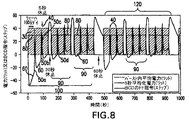
ここで図8を参照すると、一例として、例えば、集積回路リソグラフィ光源作動に対していくらか典型的なレーザシステム作動が示されており、集積回路製造ウェーハ上の複数の集積回路ダイが、フォトリソグラフィのために照射され、例えば、100ダイは、各々が、短いダイ内の停止時間を有する場合があるワット単位でバースト内電力30を示す複数のバースト40(ダイあたり1つ又はそれよりも多く)を必要とする作動が示されている。この短いダイ内の停止時間は、本発明の実施形態の態様によれば、BCDフィードフォワード補正曲線50のダイ内の部分60において反射されたBCD曲率アクチュエータ位置の変化を引き起こす遷移内に反映させることができる。ワット単位の電力、例えば、5つの第2の平均電力70は、特定のウェーハに関するバースト中にレーザシステムの出力で存在することができる。
Referring now to FIG. 8, by way of example, there is shown, for example, some typical laser system operation for integrated circuit lithography light source operation, where multiple integrated circuit dies on an integrated circuit manufacturing wafer may be For example, 100 dies may have multiple bursts 40 (one or more per die), each showing in-burst power 30 in watts, each of which may have a short die down time. The required operation is shown. This stop time in the short die is reflected in a transition that causes a change in the BCD curvature actuator position reflected at the
例えば、別のウェーハとの1つのウェーハの交換のウェーハ間の短い停止時間80はまた、例えば、出力カプラとLNMを含む例えばレーザ共鳴共振器内でレーザシステム光学列の少なくとも何らかの部分において吸収される電力としての遷移を引き起こす場合がある。このような遷移中、フィードフォワードアルゴリズムを使用する制御システムは、最初に、1つの方向にBCD曲率アクチュエータ位置を変えて、電力吸収の低減に対応し、次に、その後のウェーハ上の複数のダイを照射するために次のシリーズのバーストが発生した時、BCD曲率補正アクチュエータを反対方向に変えて電力吸収が何らかの負荷サイクルまで増大する時に発生する波面変化に対応することが分る。
For example, a
ここで図9を参照すると、概略部分ブロック図の形で本発明の実施形態の態様によるレーザシステム10の帯域幅制御システムの一例が示されている。レーザシステム10は、例えば、出力カプラ26を通じてレーザシステムを出て、中心波長、帯域幅、パルスエネルギのようなビーム品質パラメータをモニタすることができるビームモニタ48によってモニタすることができる電力レーザ光パルスビーム1を生成するために、レージングが発生するレーザチャンバ12を含むことができる。レーザチャンバ12の反対側では、当業技術で公知のように、出力カプラ26と共にレーザシステム共鳴共振器を形成する後部ミラーの役目をすることができる例えば帯域幅選択光学要素、例えば分散光学要素、例えば反射性回折格子24から成ることができる線狭化モジュール又はパッケージ(「LNM」又は「LNP」)16を位置決めすることができる。当業者はまた、レーザシステム10では、電力レーザ光パルスビーム14が、ビーム14が増幅器部分のチャンバにおける電極間の放電領域を通る選択された数の通過を成す時に励起されるように時間調節された1つ又はそれよりも多くの増幅器部分内の例えば励起レージングガス媒質においてチャンバ12からの電力ビームが増幅されるか、又は発振レーザ空洞、すなわち、主発振器電力発振器(MOPO)又は同様の多重チャンバレーザシステムとすることができるレーザ光パルスビーム14が1つ又はそれよりも多くの増幅器部分(図示せず)にシード光を注入するためのシステム(図示せず)の増幅器部分への入力を形成する多重チャンバレーザシステム、例えば主発振器電力増幅器(MOPA)レーザシステムの一部とすることができることを認識するであろう。
Referring now to FIG. 9, an example of a bandwidth control system for
LNM16の回折格子24は、例えば、そのいずれかの端部で回折格子24の裏面に取り付けられた2つの対向する支柱25の間で拡張又は収縮することによって圧縮力又は張力を回折格子24に印加することができる回折格子入射面曲率調整機構、例えば調整機構26を有することができる。このようにして、回折格子24の前面上のレーザ光パルスビームの入射面は、例えば、プリズム38、42、及び44で構成されたビーム拡大器36を通過した後、略平坦から何らかの形状を有すること、例えば曲面、例えば略凹面又は凸面の円筒形曲率に変更することができる。
The
また、LNMは、中心波長同調機構、例えばミラー46を含み、これは、中心波長、帯域幅、及び/又はF2又は単一チャンバ又は多重チャンバレーザシステムにおけるレーザシステムチャンバ12への他のハロゲンガス注入の制御に関する本出願で説明するものを含むレーザシステム10用の制御機能を実行して、適切な時に望ましい最終的レーザ出力光パルスをシステム全体から生成する、例えば1つ又はそれよりも多くのプログラムされた、又はハードウエアに組み込まれたコンピューティングプロセッサ、例えばマイクロプロセッサ、又はマイクロコントローラとすることができるレーザシステムコントローラ32の一部とすることができる中心波長コントローラによって制御することができる。
The LNM also includes a center wavelength tuning mechanism, such as a
また、上述のBCDは、例示的なものであり、かつ1つの回転を達成するための特定の数の伴う回転及びBCDステッパモータ28上のステップ数は、例示的ものにすぎず、例えば、回折格子24の入射面の形状を変える他の手段を例えば望ましい形状、例えば凹面、凸面、略円筒形の曲率を達成するために適切な力を印加する空圧、油圧、また電気的作動、例えば圧電手段とすることができ、先に参照した現在特許出願中の特許出願に説明されているように、例えば異なる方法で回折格子入射角の形状を変える2つ又はそれよりも多くのBCDアクチュエータがある場合があることが当業者によって認識されるであろう。また、アクチュエータの各々は、例えば同じモデル方程式を用いて、又は複数のアクチュエータの少なくとも1つの他のアクチュエータに対して異なるモデル方程式を用いて、レーザシステムコントローラ32における単一の帯域幅コントローラによって制御することができることが理解されるであろう。例えば、波面及び異なる種類の帯域幅、例えば中心波長付近に中心があるスペクトル内のエネルギ全体の何らかの百分率XXに関する最大値又はEXX、エネルギ積分の何らかの百分率XでのFWXM、全幅のスケールに及ぼす波形、及びその影響を各々熱又は他の遷移制御のそのモデル方程式に従って例えば回折格子に接続した別々のBCDにより、又はレーザシステム光学列の1つ及び何らかの他の態様に関する回折格子入射面形状を修正することにより、FWXM及びEXX帯域幅測定の各々における遷移に対応するように修正することができる。更に、複数のBCD26などの複数の成形アクチュエータの場合、両方は、本明細書で説明するモデル方程式に従って制御することができ、又は一方を制御することができるが他方は制御することはできず、その場合には、例えば本明細書で説明する結果を達成するために他方によって行う必要がある形状制御で本明細書で説明するように制御される一方の影響に対応する何らかの実験的に判断されたモデルに基づいて他方を制御することができる。また、1つのBCDは、帯域幅遷移制御に対して本発明の実施形態の態様に従って作動することができ、別のBCDは、回折格子24上で又は他の場所で中心波長における波面の影響を修正するために作動することができることが当業者によって認識されるであろう。
Also, the BCD described above is exemplary, and the specific number of rotations to achieve one rotation and the number of steps on the
次に、例えば、ウェーハの新たなバッチ90がフォトリソグラフィスキャナ内にシフトされた時、次のバッチの第1のウェーハが照射され始める前に若干長めの停止時間が起こり、先に照射されたバッチ90は、除去される場合がある。この時間中に電力がゼロ負荷サイクルになり、レーザシステム光学列が、相応にこのより延長された時間中に例えば約20秒に冷却される時、コントローラは、モデルのフィードフォワードアルゴリズムを用いてBCD補正アクチュエータを相応に調整する。同様に、例えば、バッチ90のウェーハの処理中の1つの群100とバッチ90のウェーハのその後の群との間で何らかの他の機能を実行する時に、約60秒の更に長めの停止時間が発生する場合がある。
Next, for example, when a
当業者は、このモデルによるフィードフォワードアルゴリズムは、時間と共に累積的であり、従って、例えば、レーザシステムが、第1のウェーハの照射においてスキャナが照射中のダイの間をシフトする時に60で示めされる小さな遷移を含む例えば本質的に冷間から熱間に行く時に、第1の群100のバッチ90のウェーハの初めに、例えばレーザシステムが長い時間アイドル状態であるように、例えば、本質的に冷間で作動して、補正される遷移が極めて大きいことを認めるであろう。しかし、ウェーハ間で例えば5秒の比較的短い停止時間後、遷移及び必要なBCD曲率補正アクチュエータ位置調整50bは、光学列が冷却するがウェーハ1が開始される前ほどではないことから比較的短い。同様に、図8で分るように、同様の約5秒の停止時間で、次の補正50cのマグニチュードは、先行する時間にわたるレーザシステム光学列では、5秒の遷移において加熱の方が大きく、冷却の方が小さく、従って必要とされる補正50cは、遷移補正フィードフォワード信号50bに必要とされるそれよりも僅かに小さいことからまだ小さい。同じく分るように、20秒の更に長い冷却の後、しかし、同じく20秒の停止時間におけるレーザシステム光学列の例えば冷却のために例えば第1の群100のバッチ90における第1のバッチのウェーハの照射完了後も、補正信号50は、第1のバッチ90における最終ウェーハに対して以前のもの50cを超えることになるが、又は更には恐らく第2の補正信号50bに対して冷間で作動するためのシステムに関して、第1のウェーハに対して、補正信号50aほど大きくなくてもよいであろう。最後に、60秒の依然として長めの停止時間後、第1のBCD曲率補正アクチュエータ信号50eは、レーザシステムがより低温の状態から作動されて、例えば60秒の更に長めの停止時間後に冷間作動されると考えられる点に対して初めの50aの補正を除き、例えば、第1のバッチにおける他の全てよりも大きいと考えられる。
Those skilled in the art will appreciate that the feedforward algorithm according to this model is cumulative over time, so that, for example, the laser system is shown at 60 when the scanner shifts between the illuminating dies in the irradiation of the first wafer. At the beginning of the wafers of the
能動帯域幅調整機構、例えば中心波長選択光学要素、例えばエシェル回折格子上の例えばレーザ光パルスビームの入射面の形状を変えるための例えばいわゆる帯域幅コントローラ(BCD)を含む図9に例示的に示すような波長選択光学要素の組合せと、例えば波面が帯域幅調整機構に入射した時に回折格子の溝を含む例えば入射面の形状を変えるために回折格子とBCDとを利用して、発生するレーザ光パルスの波面とレーザシステム内の線狭化された線とに及ぼすレーザシステム作動の影響のモデルに基づいて、帯域幅熱遷移補正するアルゴリズムを利用して能動帯域幅調整機構を能動的に制御するコントローラを含むことができるガス放電レーザシステムにおいて発生したレーザ電力レーザパルスにおける帯域幅を制御するためのガス放電レーザシステム帯域幅制御機構及び作動方法を本出願で開示していることが理解されるであろう。コントローラアルゴリズムは、ガス放電レーザシステムの光学列の少なくとも一部における電力集中履歴の関数、例えば線形関数、例えば各々がそれぞれの減衰時間定数とそれぞれの係数を含む複数の減衰関数の組合せを含むことができる。複数の減衰関数は、最大3つまでの別々の減衰関数を含むことができ、各々は、異なる減衰時間定数及び異なる係数を含むことができる。この機器及び方法は、発生したレーザ出力光パルス内の帯域幅を制御するガス放電レーザシステム帯域幅制御機構を含むことができ、これは、レーザ出力光パルスの中心波長を選択するように作動する分散光学要素、例えば能動的に制御されるBCDと組み合わせた回折格子を含むことができ、調整可能な波面形状を有する入射面、例えば回折格子中心波長選択溝を含む回折格子の面を更に含むことができる能動帯域幅調整機構を含むことができる帯域幅コントローラを含むことができ、選択中心波長を取り囲むスペクトルの帯域幅に及ぼす波面形状の影響は、入射面の選択曲率に対する帯域幅応答をプロットする曲線によって表され、更に、帯域幅調整機構の表面に入射するレーザ光の波面に及ぼすレーザシステム作動の影響のモデルに基づいて、帯域幅熱遷移補正を実行するアルゴリズムを利用して調整可能な波面形状を制御する帯域幅コントローラを含むことができ、帯域幅コントローラアルゴリズムは、入射面の曲率の選択された変化に対する帯域幅応答が比較的線形である曲線の領域において較正することができ、較正された帯域幅コントローラアルゴリズムは、入射面の曲率の選択された変化に対する帯域幅応答が比較的非線形である曲線の領域における帯域幅熱遷移補正に使用される。この機器及び方法は、発生したレーザ出力光パルス内の帯域幅を制御するガス放電レーザシステム帯域幅制御機構を含むことができ、これは、能動帯域幅調整機構を含むことができる帯域幅コントローラと、帯域幅調整機構に入射した時にレーザシステム内に発生し、かつ線狭化されるレーザ光パルスの波面に及ぼすレーザシステム作動の影響のモデルに基づく短期帯域幅制御の実施、及びガス放電レーザシステム内のレージングガス混合体中のハロゲンガス含有量を調整することに基づく長期帯域幅制御の実施を含むことができるアルゴリズムを利用して能動帯域幅調整機構を制御するコントローラとを含むことができる。この機器及び方法は、発生したレーザ出力光パルス内の帯域幅を制御するガス放電レーザシステム帯域幅制御機構を含むことができ、これは、能動帯域幅調整機構を含むことができる帯域幅コントローラと、レーザシステム光学列の少なくとも一部に掛かる熱負荷の時間平均の変化に応答する帯域幅変動のモデルに基づくフィードフォワード制御を含むアルゴリズムを利用して能動帯域幅調整機構を制御するコントローラとを含むことができる。本方法及び機器は、発生したレーザ出力光パルス内の帯域幅を制御するガス放電レーザシステム帯域幅制御機構を含むことができ、これは、レーザ出力光パルスの中心波長を選択するように作動する分散光学要素を含み、選択された波長を取り囲むスペクトルの帯域幅に及ぼす影響を選択された曲率に対する帯域幅応答をプロットする曲線によって表すことができる調整可能な波面形状を有する入射面を更に含む能動帯域幅調整機構を含む短期遷移補正機構を含む帯域幅コントローラと、帯域幅調整機構の表面に入射するレーザ光の波面に及ぼすレーザシステム作動の影響のモデルに基づいて帯域幅熱遷移補正を実行する帯域幅コントローラアルゴリズムと、ガス放電レーザシステム内のレージングガス混合体中のハロゲンガス含有量を調整することを含む長期帯域幅制御アルゴリズムとを含む。本方法及び機器は、応答が比較的線形である曲線の領域における入射面の曲率の変化によって誘発される帯域幅の変化からモデルを導出する段階と、応答が比較的非線形であるレーザシステムの望ましい作動範囲内でそのモデルを使用する段階とを含むことができる。 FIG. 9 exemplarily shows an active bandwidth adjustment mechanism, for example a center wavelength selection optical element, for example a so-called bandwidth controller (BCD) for changing the shape of the incident surface of eg a laser light pulse beam on an echelle diffraction grating. Laser light generated using a combination of such wavelength selective optical elements and, for example, a diffraction grating and a BCD to change the shape of the incident surface including the groove of the diffraction grating when the wavefront is incident on the bandwidth adjusting mechanism. Actively control the active bandwidth adjustment mechanism using a bandwidth thermal transition correction algorithm based on a model of the effect of laser system operation on the wavefront of the pulse and the line narrowed line in the laser system Gas for controlling bandwidth in laser power laser pulses generated in a gas discharge laser system that can include a controller It will be understood that discloses an electrostatic laser system bandwidth control mechanism and method of operation in the present application. The controller algorithm may include a function of power concentration history in at least a portion of the optical train of the gas discharge laser system, e.g., a linear function, e.g., a combination of a plurality of attenuation functions each including a respective decay time constant and a respective coefficient. it can. The plurality of attenuation functions can include up to three separate attenuation functions, each of which can include different attenuation time constants and different coefficients. The apparatus and method can include a gas discharge laser system bandwidth control mechanism that controls the bandwidth within the generated laser output light pulse, which operates to select the center wavelength of the laser output light pulse. It may include a diffraction grating in combination with a dispersive optical element, such as an actively controlled BCD, and further includes an entrance surface having an adjustable wavefront shape, such as a grating surface including a grating center wavelength selection groove The bandwidth controller can include an active bandwidth adjustment mechanism that can include the effect of wavefront shape on the bandwidth of the spectrum surrounding the selected center wavelength plots the bandwidth response against the selected curvature of the entrance surface. Based on a model of the effect of laser system operation on the wavefront of the laser light that is represented by the curve and incident on the surface of the bandwidth adjustment mechanism A bandwidth controller that controls an adjustable wavefront shape utilizing an algorithm that performs bandwidth thermal transition correction, wherein the bandwidth controller algorithm is configured to select a bandwidth for a selected change in curvature of the entrance surface. A calibrated bandwidth controller algorithm can be calibrated in the region of the curve where the response is relatively linear, and the calibrated bandwidth controller algorithm is able to calibrate the bandwidth in the region of the curve where the bandwidth response to the selected change in curvature of the entrance surface is relatively non-linear. Used for width heat transition correction. The apparatus and method can include a gas discharge laser system bandwidth control mechanism that controls bandwidth within the generated laser output light pulse, which includes a bandwidth controller that can include an active bandwidth adjustment mechanism; Implementation of short-term bandwidth control based on a model of the effect of laser system operation on the wavefront of a laser light pulse generated in a laser system when incident on a bandwidth adjustment mechanism and narrowed, and a gas discharge laser system A controller that controls the active bandwidth adjustment mechanism utilizing an algorithm that may include performing a long-term bandwidth control based on adjusting the halogen gas content in the lasing gas mixture within. The apparatus and method can include a gas discharge laser system bandwidth control mechanism that controls bandwidth within the generated laser output light pulse, which includes a bandwidth controller that can include an active bandwidth adjustment mechanism; A controller that controls an active bandwidth adjustment mechanism using an algorithm that includes a feedforward control based on a model of bandwidth variation in response to a change in time average of a thermal load on at least a portion of a laser system optical train. be able to. The method and apparatus can include a gas discharge laser system bandwidth control mechanism that controls the bandwidth within the generated laser output light pulse, which operates to select the center wavelength of the laser output light pulse. An active that includes a dispersive optical element and further includes an entrance surface having an adjustable wavefront shape that can be represented by a curve plotting the bandwidth response against the selected curvature, the effect on the bandwidth of the spectrum surrounding the selected wavelength Perform bandwidth thermal transition correction based on a bandwidth controller that includes a short-term transition correction mechanism, including a bandwidth adjustment mechanism, and a model of the effect of laser system operation on the wavefront of laser light incident on the surface of the bandwidth adjustment mechanism Adjust bandwidth controller algorithm and halogen gas content in lasing gas mixture in gas discharge laser system And a long-term bandwidth control algorithms including Rukoto. The method and apparatus provide for deriving a model from a change in bandwidth induced by a change in curvature of the entrance surface in a region of the curve where the response is relatively linear, and for a laser system where the response is relatively nonlinear. Using the model within the operating range.
短期による帯域幅制御に対する修正、例えばバースト内補正と上述のようなバースト間との組合せで、例えばレーザシステムパラメータは、レーザ媒質ガス成分を制御して、より長い作動期間にわたって、例えば、レーザシステムが作動してハロゲン、例えばフッ素ガスを消費する時に定期的に行われるべきである当業技術で公知であるようなガス補充間にレーザパラメータを何らかの望ましい作動内に保つためのハロゲンガス、例えばフッ素ガスの注入を用いて制御することができる。 With modifications to short-term bandwidth control, for example, a combination of intra-burst correction and burst-to-burst as described above, for example, the laser system parameters control the laser medium gas component, over a longer operating period, for example, the laser system Halogen gas, such as fluorine gas, to keep the laser parameters within any desired operation during gas replenishment as known in the art should be performed periodically when operating to consume halogen, such as fluorine gas Can be controlled using injection.
「35 U.S.C.§112」を満足するために必要とされる詳細において本特許出願に説明して例示した「ガス放電レーザ帯域幅及び中心波長制御の方法及び機器」の実施形態の特定的な態様は、上述の実施形態の態様のためのあらゆる上述の目的によって解決されるべき問題又はあらゆる他の理由又は上述の実施形態の態様の目的を達成することが十分に可能であるが、本発明の説明した実施形態の上述の態様は、単に例示的なものであり、説明的なものであり、本発明によって広く考えられている主題を表すものであると当業者によって理解されるべきである。上述の請求した実施形態の態様の範囲は、本明細書の教示内容に基づいて当業者に明らかであるか、又は明らかになると考えられる他の実施形態を完全に包含するものである。「ガス放電レーザ帯域幅及び中心波長制御の方法及び機器」の範囲は、専らかつ完全に特許請求の範囲によって限定されるものであり、特許請求の範囲の詳細説明を超えるものは一切ない。単数形でのこのような請求項の要素への言及は、明示的に説明されていない限り、このような請求項の要素を解釈する際に「1つ及び1つのみ」ではなく、むしろ「1つ又はそれよりも多く」を意味することを意図し、かつ意味するものである。当業者に公知か又は後で公知になる実施形態の上述の態様の要素のいずれかに対する全ての構造的及び機能的均等物は、引用により明白に本明細書に組み込まれており、特許請求の範囲によって包含されるように想定されているものである。本明細書において及び/又は特許請求の範囲において使用され、かつ本出願内の明細書及び/又は特許請求の範囲において明白に特定の意味を与えられたあらゆる用語は、このような用語に対する辞書的又は他の一般的な意味を問わず、そのような意味を有するものとする。実施形態の態様として本明細書において説明した装置又は方法は、本明細書で開示する実施形態の態様によって解決されるように求められる各々の及び全ての問題に対処すること、すなわち、本発明の特許請求の範囲によって包含されることは意図せず、また必要でもない。本発明の開示内容におけるいかなる要素、構成要素、方法段階も、その要素、構成要素、方法段階が明示的に特許請求の範囲で詳細に説明されているか否かを問わず、一般に捧げられることは意図していない。特許請求の範囲のいかなる請求項の要素も、語句「のための手段」を使用して明白に詳細に説明されるか又は方法の請求項の場合にはその要素が「作用」ではなくて「段階」と詳細に説明されていない限り、「35 U.S.C.§112」第6段の規定の下で解釈されるべきではない。 Of the “gas discharge laser bandwidth and center wavelength control method and apparatus” embodiment described and illustrated in this patent application in the details required to satisfy “35 USC §112”. Although specific aspects are sufficiently possible to achieve the problem to be solved by any of the above-mentioned objectives for the aspects of the above-described embodiments or any other reason or purpose of aspects of the above-described embodiments. It will be understood by those skilled in the art that the above-described aspects of the described embodiments of the present invention are merely exemplary, illustrative, and represent a subject that is broadly contemplated by the present invention. Should. The scope of the aspects of the above-described claimed embodiments is intended to fully encompass other embodiments that will be apparent, or will be apparent, to those skilled in the art based on the teachings herein. The scope of the “method and apparatus for controlling the gas discharge laser bandwidth and center wavelength” is limited exclusively and completely by the claims, and there is nothing beyond the detailed description of the claims. Reference to an element of such claim in the singular is not “one and only one” but rather “one and only one” when interpreting the element of such claim, unless explicitly stated. It is intended and meant to mean "one or more". All structural and functional equivalents to any of the elements of the above-described aspects of embodiments known to those skilled in the art or later known are expressly incorporated herein by reference, and It is intended to be covered by a range. Any term used in this specification and / or in the claims, and explicitly given a specific meaning in the specification and / or claims within this application is lexicographically related to such terms. Or, it shall have such meaning regardless of other general meanings. The apparatus or method described herein as an aspect of an embodiment addresses each and every problem sought to be solved by the aspects of the embodiments disclosed herein, i.e., It is not intended or required to be encompassed by the claims. Any element, component, or method step in the disclosure of the present invention is generally devoted to whether or not that element, component, or method step is explicitly described in detail in the claims. Not intended. Any claim element in a claim is clearly described in detail using the phrase “means for” or, in the case of a method claim, that element is not an “action”. Unless stated in detail as “stage”, it should not be construed under the provisions of the sixth stage of “35 USC § 112”.
先に開示した本発明の実施形態の態様は、好ましい実施形態のみであることを意図しており、本発明の開示内容をいかなる点においても特に特定の好ましい実施形態だけに限定しないことを意図することが当業者によって理解されるであろう。当業者によって理解かつ認識されると思われる開示した本発明の実施形態の開示した態様には、多くの変更及び修正を行うことができる。特許請求の範囲は、その範囲及び意味において、本発明の実施形態の開示する態様だけでなく、当業者に明らかになると思われるこのような均等物及び他の修正及び変更を網羅するように想定されている。上述の開示及び請求した本発明の実施形態の態様に対する変更及び修正に加えて、他のものも実施することができると考えられる。 The aspects of the embodiments of the invention disclosed above are intended to be only preferred embodiments, and are not intended to limit the disclosure of the invention in any way to any particular preferred embodiment. It will be understood by those skilled in the art. Many changes and modifications may be made to the disclosed aspects of the disclosed embodiments of the invention that will be understood and appreciated by those skilled in the art. The claims are intended to cover, in their scope and meaning, not only the disclosed aspects of the embodiments of the present invention but also those equivalents and other modifications and variations that would be apparent to a person skilled in the art. Has been. In addition to the changes and modifications to the aspects of the above-disclosed and claimed embodiments of the present invention, it is contemplated that others can be implemented.
30 バースト内電力
40 バースト
50 BCDフィードフォワード補正曲線
30 Power in
Claims (12)
レーザ出力光パルスに対する中心波長を選択するように作動する回折格子を含む能動帯域幅調節機構であって、前記回折格子が調節可能な波面形状を有する入射面を有し、選択された中心波長を取り囲むスペクトルの帯域幅に及ぼす前記波面形状の影響が、前記入射面の選択された曲率に対する帯域幅の応答をプロットする曲線によって表される能動帯域幅調節機構、
を含む帯域幅コントローラと、
前記回折格子の入射面に入射するレーザ光の波面に及ぼすレーザシステム作動の影響のモデルに基づいて、帯域幅熱遷移補正を実行するアルゴリズムを利用して調整可能な波面形状を制御する帯域幅コントローラと、
を含み、
前記コントローラアルゴリズムは、前記入射面の曲率の選択された変化に対する前記帯域幅応答が比較的線形である前記曲線の領域において動作するよう較正され、該較正されたコントローラアルゴリズムは、該入射面の曲率の選択された変化に対する該帯域幅応答が比較的非線形である前記曲線の領域における帯域幅熱遷移補正のために使用される、
ことを特徴とするガス放電レーザシステム帯域幅制御機構。 A gas discharge laser system bandwidth control mechanism for controlling a bandwidth in a laser output light pulse generated in a gas discharge laser system,
A diffraction grating operable to select a center wavelength for the laser output light pulse A including active band width adjustment mechanism has an incident surface on which the diffraction grating has an adjustable wavefront shape, the central wavelength selected the influence of the wavefront shape, the incident surface of the selected active band width adjustment mechanism represented by the curve plotting the response of bandwidth to the curvature on the bandwidth of the spectrum surrounding the,
A bandwidth controller including:
A bandwidth controller that controls an adjustable wavefront shape using an algorithm that performs bandwidth thermal transition correction based on a model of the effect of laser system operation on the wavefront of laser light incident on the entrance surface of the diffraction grating When,
Including
The controller algorithm is calibrated to operate in the region of the curve where the bandwidth response to a selected change in curvature of the entrance surface is relatively linear, the calibrated controller algorithm band-width response to a selected change is used for bandwidth heat transition correction in the region of the curve is relatively non-linear,
A bandwidth control mechanism of a gas discharge laser system characterized by the above.
ことを更に含むことを特徴とする請求項1に記載の機器。 The controller algorithm includes a function of optical power concentration history at least a portion of the optical train of the gas discharge laser system,
The device of claim 1 further comprising:
ことを更に含むことを特徴とする請求項1に記載の機器。 The controller algorithm includes a linear function of the optical power concentration history at least a portion of the optical train of the gas discharge laser system,
The device of claim 1 further comprising:
ことを更に含むことを特徴とする請求項1に記載の機器。 The controller algorithm includes a combination of a plurality of attenuation functions, each including a respective attenuation time constant and a respective coefficient,
The device of claim 1 further comprising:
ことを更に含むことを特徴とする請求項2に記載の機器。 The controller algorithm includes a combination of a plurality of attenuation functions, each including a respective attenuation time constant and a respective coefficient,
The device of claim 2 further comprising:
ことを更に含むことを特徴とする請求項3に記載の機器。 The controller algorithm includes a combination of a plurality of attenuation functions, each including a respective attenuation time constant and a respective coefficient,
The device of claim 3 further comprising:
ことを更に含むことを特徴とする請求項4に記載の機器。 The plurality of attenuation functions includes up to three separate attenuation functions;
The device of claim 4, further comprising:
ことを更に含むことを特徴とする請求項5に記載の機器。 The plurality of attenuation functions includes up to three separate attenuation functions;
6. The device of claim 5, further comprising:
ことを更に含むことを特徴とする請求項6に記載の機器。 The plurality of attenuation functions includes up to three separate attenuation functions;
The device of claim 6 further comprising:
ことを更に含むことを特徴とする請求項7に記載の機器。 Each of the plurality of decay functions includes a different decay time constant and a different coefficient;
The device of claim 7 further comprising:
ことを更に含むことを特徴とする請求項8に記載の機器。 Each of the plurality of decay functions includes a different decay time constant and a different coefficient;
9. The device of claim 8, further comprising:
ことを更に含むことを特徴とする請求項9に記載の機器。 Each of the plurality of decay functions includes a different decay time constant and a different coefficient;
10. The device of claim 9, further comprising:
Applications Claiming Priority (5)
| Application Number | Priority Date | Filing Date | Title |
|---|---|---|---|
| US11/000,571 US20060114956A1 (en) | 2004-11-30 | 2004-11-30 | High power high pulse repetition rate gas discharge laser system bandwidth management |
| US11/000,571 | 2004-11-30 | ||
| US11/254,282 | 2005-10-20 | ||
| US11/254,282 US7643522B2 (en) | 2004-11-30 | 2005-10-20 | Method and apparatus for gas discharge laser bandwidth and center wavelength control |
| PCT/US2005/043059 WO2006060361A2 (en) | 2004-11-30 | 2005-11-28 | Method and apparatus for gas discharge laser bandwidth and center wavelength control |
Publications (3)
| Publication Number | Publication Date |
|---|---|
| JP2008527683A JP2008527683A (en) | 2008-07-24 |
| JP2008527683A5 JP2008527683A5 (en) | 2009-01-22 |
| JP5265921B2 true JP5265921B2 (en) | 2013-08-14 |
Family
ID=36565614
Family Applications (1)
| Application Number | Title | Priority Date | Filing Date |
|---|---|---|---|
| JP2007544430A Active JP5265921B2 (en) | 2004-11-30 | 2005-11-28 | Method and apparatus for gas discharge laser bandwidth and center wavelength control |
Country Status (4)
| Country | Link |
|---|---|
| US (1) | US7643522B2 (en) |
| JP (1) | JP5265921B2 (en) |
| TW (1) | TWI283093B (en) |
| WO (1) | WO2006060361A2 (en) |
Families Citing this family (26)
| Publication number | Priority date | Publication date | Assignee | Title |
|---|---|---|---|---|
| US7999915B2 (en) * | 2005-11-01 | 2011-08-16 | Cymer, Inc. | Laser system |
| US7715459B2 (en) * | 2005-11-01 | 2010-05-11 | Cymer, Inc. | Laser system |
| US7746913B2 (en) | 2005-11-01 | 2010-06-29 | Cymer, Inc. | Laser system |
| US20090296755A1 (en) * | 2005-11-01 | 2009-12-03 | Cymer, Inc. | Laser system |
| US7778302B2 (en) * | 2005-11-01 | 2010-08-17 | Cymer, Inc. | Laser system |
| US7643529B2 (en) * | 2005-11-01 | 2010-01-05 | Cymer, Inc. | Laser system |
| US7885309B2 (en) * | 2005-11-01 | 2011-02-08 | Cymer, Inc. | Laser system |
| US7920616B2 (en) * | 2005-11-01 | 2011-04-05 | Cymer, Inc. | Laser system |
| US20090296758A1 (en) * | 2005-11-01 | 2009-12-03 | Cymer, Inc. | Laser system |
| US7630424B2 (en) * | 2005-11-01 | 2009-12-08 | Cymer, Inc. | Laser system |
| WO2007053335A2 (en) * | 2005-11-01 | 2007-05-10 | Cymer, Inc. | Laser system |
| US7822084B2 (en) * | 2006-02-17 | 2010-10-26 | Cymer, Inc. | Method and apparatus for stabilizing and tuning the bandwidth of laser light |
| US7852889B2 (en) * | 2006-02-17 | 2010-12-14 | Cymer, Inc. | Active spectral control of DUV light source |
| US8259764B2 (en) | 2006-06-21 | 2012-09-04 | Cymer, Inc. | Bandwidth control device |
| JP5114767B2 (en) * | 2006-10-10 | 2013-01-09 | 株式会社小松製作所 | Narrowband laser spectral width adjustment device |
| US7659529B2 (en) * | 2007-04-13 | 2010-02-09 | Cymer, Inc. | Method and apparatus for vibration reduction in laser system line narrowing unit wavelength selection optical element |
| US8144739B2 (en) | 2008-10-24 | 2012-03-27 | Cymer, Inc. | System method and apparatus for selecting and controlling light source bandwidth |
| US8837536B2 (en) * | 2010-04-07 | 2014-09-16 | Cymer, Llc | Method and apparatus for controlling light bandwidth |
| JP5755068B2 (en) * | 2011-07-27 | 2015-07-29 | 株式会社小松製作所 | Narrowband laser spectral width adjustment device |
| JP6113426B2 (en) | 2011-09-08 | 2017-04-12 | ギガフォトン株式会社 | Master oscillator system and laser device |
| JP5832581B2 (en) * | 2014-04-28 | 2015-12-16 | 株式会社小松製作所 | Narrowband laser spectral width adjustment device |
| US10816905B2 (en) * | 2015-04-08 | 2020-10-27 | Cymer, Llc | Wavelength stabilization for an optical source |
| JP6585174B2 (en) | 2015-08-07 | 2019-10-02 | ギガフォトン株式会社 | Narrow band laser equipment |
| WO2017134745A1 (en) | 2016-02-02 | 2017-08-10 | ギガフォトン株式会社 | Narrow band laser device |
| WO2018229823A1 (en) * | 2017-06-12 | 2018-12-20 | ギガフォトン株式会社 | Laser device, laser device managing system, and laser device management method |
| JP2023183776A (en) | 2022-06-16 | 2023-12-28 | ギガフォトン株式会社 | Euv light generation system, and method for manufacturing electronic device |
Family Cites Families (36)
| Publication number | Priority date | Publication date | Assignee | Title |
|---|---|---|---|---|
| US5095492A (en) * | 1990-07-17 | 1992-03-10 | Cymer Laser Technologies | Spectral narrowing technique |
| US5898725A (en) * | 1997-01-21 | 1999-04-27 | Cymer, Inc. | Excimer laser with greater spectral bandwidth and beam stability |
| US5982800A (en) * | 1997-04-23 | 1999-11-09 | Cymer, Inc. | Narrow band excimer laser |
| JP4102457B2 (en) * | 1997-05-09 | 2008-06-18 | 株式会社小松製作所 | Narrow band laser equipment |
| US5852627A (en) * | 1997-09-10 | 1998-12-22 | Cymer, Inc. | Laser with line narrowing output coupler |
| US6028879A (en) * | 1997-06-04 | 2000-02-22 | Cymer, Inc. | Narrow band laser with etalon based output coupler |
| JP3717020B2 (en) * | 1997-06-30 | 2005-11-16 | 株式会社小松製作所 | Bending mechanism of reflective wavelength selective element |
| US6192064B1 (en) * | 1997-07-01 | 2001-02-20 | Cymer, Inc. | Narrow band laser with fine wavelength control |
| US6212217B1 (en) * | 1997-07-01 | 2001-04-03 | Cymer, Inc. | Smart laser with automated beam quality control |
| ES2195346T3 (en) * | 1997-07-01 | 2003-12-01 | Cymer Inc | VERY NARROW BAND LASER WITH UNSTABLE RESONANCE CAVITY. |
| US6094448A (en) * | 1997-07-01 | 2000-07-25 | Cymer, Inc. | Grating assembly with bi-directional bandwidth control |
| USRE38054E1 (en) * | 1997-07-18 | 2003-04-01 | Cymer, Inc. | Reliable, modular, production quality narrow-band high rep rate F2 laser |
| US5978409A (en) * | 1998-09-28 | 1999-11-02 | Cymer, Inc. | Line narrowing apparatus with high transparency prism beam expander |
| US6529531B1 (en) * | 1997-07-22 | 2003-03-04 | Cymer, Inc. | Fast wavelength correction technique for a laser |
| US6671294B2 (en) * | 1997-07-22 | 2003-12-30 | Cymer, Inc. | Laser spectral engineering for lithographic process |
| US6317447B1 (en) * | 2000-01-25 | 2001-11-13 | Cymer, Inc. | Electric discharge laser with acoustic chirp correction |
| US6721340B1 (en) * | 1997-07-22 | 2004-04-13 | Cymer, Inc. | Bandwidth control technique for a laser |
| US6853653B2 (en) * | 1997-07-22 | 2005-02-08 | Cymer, Inc. | Laser spectral engineering for lithographic process |
| US6621846B1 (en) * | 1997-07-22 | 2003-09-16 | Cymer, Inc. | Electric discharge laser with active wavelength chirp correction |
| US6078599A (en) * | 1997-07-22 | 2000-06-20 | Cymer, Inc. | Wavelength shift correction technique for a laser |
| US6141081A (en) * | 1997-08-08 | 2000-10-31 | Cymer, Inc. | Stepper or scanner having two energy monitors for a laser |
| US6163559A (en) * | 1998-06-22 | 2000-12-19 | Cymer, Inc. | Beam expander for ultraviolet lasers |
| US6567450B2 (en) * | 1999-12-10 | 2003-05-20 | Cymer, Inc. | Very narrow band, two chamber, high rep rate gas discharge laser system |
| US6493374B1 (en) * | 1999-09-03 | 2002-12-10 | Cymer, Inc. | Smart laser with fast deformable grating |
| US6965624B2 (en) * | 1999-03-17 | 2005-11-15 | Lambda Physik Ag | Laser gas replenishment method |
| US6625191B2 (en) * | 1999-12-10 | 2003-09-23 | Cymer, Inc. | Very narrow band, two chamber, high rep rate gas discharge laser system |
| US6034978A (en) * | 1999-05-12 | 2000-03-07 | Cymer, Inc. | Gas discharge laser with gas temperature control |
| US6496528B2 (en) * | 1999-09-03 | 2002-12-17 | Cymer, Inc. | Line narrowing unit with flexural grating mount |
| US6532247B2 (en) * | 2000-02-09 | 2003-03-11 | Cymer, Inc. | Laser wavelength control unit with piezoelectric driver |
| JP2003518757A (en) * | 1999-12-22 | 2003-06-10 | サイマー, インコーポレイテッド | Narrowing laser using bidirectional beam expansion |
| US6650666B2 (en) * | 2000-02-09 | 2003-11-18 | Cymer, Inc. | Laser wavelength control unit with piezoelectric driver |
| US6408260B1 (en) * | 2000-02-16 | 2002-06-18 | Cymer, Inc. | Laser lithography quality alarm system |
| US6738406B2 (en) * | 2000-06-19 | 2004-05-18 | Lambda Physik Ag | Precision measurement of wavelengths emitted by a molecular fluorine laser at 157nm |
| US6690704B2 (en) * | 2001-04-09 | 2004-02-10 | Cymer, Inc. | Control system for a two chamber gas discharge laser |
| US6760358B1 (en) * | 2001-06-07 | 2004-07-06 | Lambda Physik Ag | Line-narrowing optics module having improved mechanical performance |
| US6735225B2 (en) * | 2001-06-07 | 2004-05-11 | Lambda Physik Ag | Chirp compensation method and apparatus |
-
2005
- 2005-10-20 US US11/254,282 patent/US7643522B2/en active Active
- 2005-11-25 TW TW094141474A patent/TWI283093B/en active
- 2005-11-28 WO PCT/US2005/043059 patent/WO2006060361A2/en active Application Filing
- 2005-11-28 JP JP2007544430A patent/JP5265921B2/en active Active
Also Published As
| Publication number | Publication date |
|---|---|
| TWI283093B (en) | 2007-06-21 |
| WO2006060361A3 (en) | 2009-04-16 |
| WO2006060361A2 (en) | 2006-06-08 |
| US20060114958A1 (en) | 2006-06-01 |
| US7643522B2 (en) | 2010-01-05 |
| JP2008527683A (en) | 2008-07-24 |
| TW200627739A (en) | 2006-08-01 |
Similar Documents
| Publication | Publication Date | Title |
|---|---|---|
| JP5265921B2 (en) | Method and apparatus for gas discharge laser bandwidth and center wavelength control | |
| US8098698B2 (en) | Active spectral control of DUV laser light source | |
| JP4798687B2 (en) | Narrow band laser equipment | |
| US6240110B1 (en) | Line narrowed F2 laser with etalon based output coupler | |
| US6392743B1 (en) | Control technique for microlithography lasers | |
| JP4911558B2 (en) | Narrow band laser equipment | |
| US20080253413A1 (en) | Laser lithography system with improved bandwidth control | |
| US20020186741A1 (en) | Very narrow band excimer or molecular fluorine laser | |
| US8837536B2 (en) | Method and apparatus for controlling light bandwidth | |
| US6735225B2 (en) | Chirp compensation method and apparatus | |
| US6597462B2 (en) | Laser wavelength and bandwidth monitor | |
| US6516013B1 (en) | Laser beam monitoring apparatus and method | |
| JP2004271498A (en) | Computing method of spectral index value of laser beam, arithmetic unit of spectral index value of laser beam, and measuring device of spectral waveform | |
| JP2011249818A (en) | Band narrowing laser device | |
| US6667804B1 (en) | Temperature compensation method for wavemeters | |
| JP4094307B2 (en) | Gas laser device | |
| US6807205B1 (en) | Precise monitor etalon calibration technique | |
| JP5312567B2 (en) | Narrow band laser equipment | |
| Dunstan et al. | Active Spectral Control of DUV light sources for OPE minimization | |
| JP5832581B2 (en) | Narrowband laser spectral width adjustment device | |
| JP2939633B2 (en) | Control device for narrow band oscillation excimer laser | |
| WO2021048947A1 (en) | Laser device, and manufacturing method for electronic device | |
| JP2015092591A (en) | Band narrowing laser device | |
| JP5607592B2 (en) | Narrow band laser equipment |
Legal Events
| Date | Code | Title | Description |
|---|---|---|---|
| A521 | Request for written amendment filed |
Free format text: JAPANESE INTERMEDIATE CODE: A523 Effective date: 20081128 |
|
| A621 | Written request for application examination |
Free format text: JAPANESE INTERMEDIATE CODE: A621 Effective date: 20081128 |
|
| A977 | Report on retrieval |
Free format text: JAPANESE INTERMEDIATE CODE: A971007 Effective date: 20110815 |
|
| A131 | Notification of reasons for refusal |
Free format text: JAPANESE INTERMEDIATE CODE: A131 Effective date: 20110822 |
|
| A601 | Written request for extension of time |
Free format text: JAPANESE INTERMEDIATE CODE: A601 Effective date: 20111122 |
|
| A602 | Written permission of extension of time |
Free format text: JAPANESE INTERMEDIATE CODE: A602 Effective date: 20111130 |
|
| A521 | Request for written amendment filed |
Free format text: JAPANESE INTERMEDIATE CODE: A523 Effective date: 20120222 |
|
| A131 | Notification of reasons for refusal |
Free format text: JAPANESE INTERMEDIATE CODE: A131 Effective date: 20121203 |
|
| A601 | Written request for extension of time |
Free format text: JAPANESE INTERMEDIATE CODE: A601 Effective date: 20130304 |
|
| A602 | Written permission of extension of time |
Free format text: JAPANESE INTERMEDIATE CODE: A602 Effective date: 20130311 |
|
| A521 | Request for written amendment filed |
Free format text: JAPANESE INTERMEDIATE CODE: A523 Effective date: 20130403 |
|
| TRDD | Decision of grant or rejection written | ||
| A01 | Written decision to grant a patent or to grant a registration (utility model) |
Free format text: JAPANESE INTERMEDIATE CODE: A01 Effective date: 20130430 |
|
| A61 | First payment of annual fees (during grant procedure) |
Free format text: JAPANESE INTERMEDIATE CODE: A61 Effective date: 20130502 |
|
| R150 | Certificate of patent or registration of utility model |
Free format text: JAPANESE INTERMEDIATE CODE: R150 Ref document number: 5265921 Country of ref document: JP Free format text: JAPANESE INTERMEDIATE CODE: R150 |
|
| S111 | Request for change of ownership or part of ownership |
Free format text: JAPANESE INTERMEDIATE CODE: R313111 |
|
| R350 | Written notification of registration of transfer |
Free format text: JAPANESE INTERMEDIATE CODE: R350 |
|
| RD02 | Notification of acceptance of power of attorney |
Free format text: JAPANESE INTERMEDIATE CODE: R3D02 |
|
| R250 | Receipt of annual fees |
Free format text: JAPANESE INTERMEDIATE CODE: R250 |
|
| R250 | Receipt of annual fees |
Free format text: JAPANESE INTERMEDIATE CODE: R250 |
|
| R250 | Receipt of annual fees |
Free format text: JAPANESE INTERMEDIATE CODE: R250 |
|
| R250 | Receipt of annual fees |
Free format text: JAPANESE INTERMEDIATE CODE: R250 |
|
| R250 | Receipt of annual fees |
Free format text: JAPANESE INTERMEDIATE CODE: R250 |
|
| R250 | Receipt of annual fees |
Free format text: JAPANESE INTERMEDIATE CODE: R250 |
|
| R250 | Receipt of annual fees |
Free format text: JAPANESE INTERMEDIATE CODE: R250 |
|
| R250 | Receipt of annual fees |
Free format text: JAPANESE INTERMEDIATE CODE: R250 |