JP5265895B2 - Cell for performing electroluminescence measurements - Google Patents
Cell for performing electroluminescence measurements Download PDFInfo
- Publication number
- JP5265895B2 JP5265895B2 JP2007213073A JP2007213073A JP5265895B2 JP 5265895 B2 JP5265895 B2 JP 5265895B2 JP 2007213073 A JP2007213073 A JP 2007213073A JP 2007213073 A JP2007213073 A JP 2007213073A JP 5265895 B2 JP5265895 B2 JP 5265895B2
- Authority
- JP
- Japan
- Prior art keywords
- measurement cell
- cell cavity
- cavity
- measurement
- fluid
- Prior art date
- Legal status (The legal status is an assumption and is not a legal conclusion. Google has not performed a legal analysis and makes no representation as to the accuracy of the status listed.)
- Active
Links
Images
Classifications
-
- G—PHYSICS
- G01—MEASURING; TESTING
- G01N—INVESTIGATING OR ANALYSING MATERIALS BY DETERMINING THEIR CHEMICAL OR PHYSICAL PROPERTIES
- G01N21/00—Investigating or analysing materials by the use of optical means, i.e. using sub-millimetre waves, infrared, visible or ultraviolet light
- G01N21/75—Systems in which material is subjected to a chemical reaction, the progress or the result of the reaction being investigated
- G01N21/76—Chemiluminescence; Bioluminescence
-
- G—PHYSICS
- G01—MEASURING; TESTING
- G01N—INVESTIGATING OR ANALYSING MATERIALS BY DETERMINING THEIR CHEMICAL OR PHYSICAL PROPERTIES
- G01N21/00—Investigating or analysing materials by the use of optical means, i.e. using sub-millimetre waves, infrared, visible or ultraviolet light
- G01N21/62—Systems in which the material investigated is excited whereby it emits light or causes a change in wavelength of the incident light
- G01N21/66—Systems in which the material investigated is excited whereby it emits light or causes a change in wavelength of the incident light electrically excited, e.g. electroluminescence
-
- G—PHYSICS
- G01—MEASURING; TESTING
- G01N—INVESTIGATING OR ANALYSING MATERIALS BY DETERMINING THEIR CHEMICAL OR PHYSICAL PROPERTIES
- G01N21/00—Investigating or analysing materials by the use of optical means, i.e. using sub-millimetre waves, infrared, visible or ultraviolet light
- G01N21/01—Arrangements or apparatus for facilitating the optical investigation
- G01N21/03—Cuvette constructions
- G01N21/05—Flow-through cuvettes
Abstract
Description
本発明は、長楕円形経路の形状をした測定セルキャビティと、測定セルキャビティ中へ流体を導入するための後者に向けて測定セルキャビティの縦方向に対して交差する方向に伸びる流体流入口経路と前記測定セルキャビティから流体を排出するための流体流出口経路(6)を持つ測定セル筐体と前記測定セルキャビティ上または内の少なくとも一つの作用電極および対向電極と、前記測定セルキャビティ中のエレクトロルミネッセンス効果を観察するための測定セル筐体中の光学観察素子とからなるサンプル分析用のエレクトロルミネッセンス測定を行うためのセルに関する。 The present invention relates to a measurement cell cavity in the form of an elliptical path and a fluid inlet path extending in a direction intersecting the longitudinal direction of the measurement cell cavity towards the latter for introducing fluid into the measurement cell cavity A measurement cell housing having a fluid outlet path (6) for discharging fluid from the measurement cell cavity, at least one working electrode and a counter electrode on or in the measurement cell cavity, and in the measurement cell cavity The present invention relates to a cell for performing electroluminescence measurement for sample analysis, comprising an optical observation element in a measurement cell housing for observing an electroluminescence effect.
エレクトロルミネッセンステスト、特にそのような測定セルを用いて免疫学的検定により、サンプルを分析するための種類および方法の測定セルは、たとえばDE4342942A1、DE19803528A1、WO89/10551A1およびWO90/11511から公知であり、そのため本発明の主課題に関する基礎的技術の理解のために、これらの出版物を参照する。 Measuring cells of the type and method for analyzing samples by means of electroluminescence tests, in particular immunoassays using such measuring cells, are known, for example from DE 4342942A1, DE 19803528A1, WO 89 / 10551A1 and WO 90/11511, Therefore, reference is made to these publications for an understanding of the basic techniques relating to the main subject of the present invention.
エレクトロルミネッセンスにより液体サンプルを分析するときには、前記液体サンプル中に含まれる物質(検体)の濃度を、通常求めることになる。医療分野においては、特に血液、尿、唾液などの体液の分析が、たとえば、抗体、抗原、ホルモンなどの底に含まれる検体の見地から非常に重要である。本発明は、特に、エレクトロルミネッセンス結合反応テストによるサンプルの分析に適用される改良された測定セルを参照する。 When analyzing a liquid sample by electroluminescence, the concentration of a substance (analyte) contained in the liquid sample is usually obtained. In the medical field, analysis of body fluids such as blood, urine, and saliva is very important from the viewpoint of specimens contained in the bottom of, for example, antibodies, antigens, and hormones. The invention refers in particular to an improved measuring cell applied to the analysis of samples by electroluminescence binding reaction tests.
そのようなテストにおける代表的な測定方法は、測定セル中の液体および/または混合物の多重交換を含む。従って、代表的測定の間、第1混合物は、測定セルキャビティ中の流体流入口経路を経由して、清浄化された測定セル中に誘導される。前記第1混合物は、サンプル、試薬および磁性粒子の培養物である。現在考えられているテストにおいては、エレクトロルミネッセンス標的物質を用いてマークされまた前記分析の特性でもある複合分子は、これらの磁性粒子に固定される。そのような固定は、特定の1対の生化学的結合パートナーにより行われ、それにより、特に、ストレプトアビジン−ビオチン対が有用であることがわかっている。前記磁性粒子は、たとえば、ストレプトアビジンポリマーで被覆され、一方ビオチンは、複合分子に結合されている。 A typical measurement method in such a test involves multiple exchanges of liquids and / or mixtures in the measurement cell. Thus, during a representative measurement, the first mixture is directed into the cleaned measurement cell via a fluid inlet path in the measurement cell cavity. The first mixture is a culture of samples, reagents and magnetic particles. In the currently contemplated test, complex molecules that are marked with an electroluminescent target substance and that are also characteristic of the analysis are immobilized on these magnetic particles. Such immobilization is performed by a specific pair of biochemical binding partners, which have proved particularly useful, especially the streptavidin-biotin pair. The magnetic particles are, for example, coated with streptavidin polymer, while biotin is bound to a complex molecule.
前記測定セルにおいては、前記磁性粒子は、作用電極近くに配置された磁石の磁場中で、そこに結合された標識錯体と共に、作用電極表面にトラップされる。このことは、第1混合物の連続的流れのあいだに行われ、それにより、培養流体は、流体流出口経路を経由して、測定セルキャビティから排出される。培養流体を放出しながら作用電極上に前記磁性粒子を蓄積することは、B/F分離(bound free separation)と呼ばれている。 In the measurement cell, the magnetic particles are trapped on the surface of the working electrode together with the label complex bound thereto in the magnetic field of a magnet arranged near the working electrode. This takes place during the continuous flow of the first mixture, whereby the culture fluid is discharged from the measurement cell cavity via the fluid outlet path. Accumulating the magnetic particles on the working electrode while discharging the culture fluid is called B / F separation (bound free separation).
前記磁性粒子をトラップした後、測定試薬を次の工程でセル中に導入し、それにより、前記磁性粒子を前記測定試薬を用いて洗浄する。この洗浄工程は、作用電極から潜在的には電気化学的反応を阻害する未結合成分を除去することである。 After trapping the magnetic particles, a measurement reagent is introduced into the cell in the next step, whereby the magnetic particles are washed with the measurement reagent. This washing step is to remove unbound components that potentially inhibit the electrochemical reaction from the working electrode.
その後、エレクトロルミネッセンス反応が、前記作用電極に電位を印加することにより引き起こされ、それにより、発光光の強度は、ホトセンサーにより検出され、作用電極の表面上の標識化磁性粒子の濃度の尺度として評価され、またそれにより、この濃度が再び、サンプル中の検体濃度の尺度としての機能を果たす。 An electroluminescent reaction is then triggered by applying a potential to the working electrode, whereby the intensity of the emitted light is detected by a photosensor and as a measure of the concentration of labeled magnetic particles on the surface of the working electrode. This concentration is then evaluated, and this concentration again serves as a measure of analyte concentration in the sample.
エレクトロルミネッセンス測定後、前記セルは、通常洗浄液体で洗浄され、それは、さらなる工程で、次の測定用セルの状態調節のために、測定試薬と共に排出される。 After the electroluminescence measurement, the cell is usually washed with a washing liquid, which in a further step is discharged with the measuring reagent for the conditioning of the next measuring cell.
上記の洗浄工程が、効率的であることが、測定の品質のために、必須であり、前記培養から分離される測定試薬と磁性粒子の混合物中には、たとえば、サンプル成分として、妨害成分の最小可能性量が含まれる。そのような、妨害成分は、測定信号の変化を生じさせる。そのような測定干渉が、マトリックス効果とも呼ばれている。もし上記の洗浄工程が、あまり手荒く行われると、負の効果を引き起こすことにもなり、もし、たとえば、あまりにも大きな流速、乱流などによる場合には、磁性粒子は、作用電極上の位置から取り除かれる。 It is essential for the quality of the measurement that the above washing step is efficient. In the mixture of the measurement reagent and magnetic particles separated from the culture, for example, as a sample component, an interference component The minimum possible quantity is included. Such disturbing components cause changes in the measurement signal. Such measurement interference is also called a matrix effect. If the above washing process is carried out too rough, it can also cause negative effects, for example if the flow rate is too high, turbulent, etc. Removed.
公知の測定セルにおいては、流体流入口経路および流体流出口経路は、長楕円形状の測定セルキャビティの長手方向に直交して、測定セルキャビティに合流し、その結果、流体が、測定セルを通過するときに、各流体流れは、測定セルキャビティ内に誘導されるときは、角度90゜だけ急激に偏向され−最終的には、測定セルキャビティから放出されるときには、角度90゜だけ再び偏向される。そのような流体経路の形状は、構造と生産の理由から確立されたものであり、またそれ以後、測定セルの最適な操作に適していると考えられてきた。公知の測定セルにおいては、その筐体は、流体流入口経路および流体流出口経路より分散されたまたその横面の1つにより測定セルキャビティを区画するベースブロックを有し、作用電極が測定セルキャビティの周辺面上に設けられている。前記流体経路は、このベースブロックを貫通し、前記ベースブロックの測定セルキャビティの周辺面の面に対して直交して伸びている。洗浄器として作用しまた中央クリアランスを持っているスペーサーが、前記ベースブロック上に置かれて、測定セルキャビティの側壁の制限を、内部輪郭をもって形成している。アクリルガラスパネルは、光学窓としてスペーサー洗浄器上に置かれて、その上に、作用電極の反対側に、対向電極が設けられている。 In known measurement cells, the fluid inlet and fluid outlet paths merge into the measurement cell cavity perpendicular to the longitudinal direction of the ellipsoidal measurement cell cavity so that the fluid passes through the measurement cell. When each fluid flow is directed into the measurement cell cavity, it is deflected abruptly by an angle of 90 °-eventually, it is deflected again by an angle of 90 ° when discharged from the measurement cell cavity. The Such fluid path shapes have been established for structural and production reasons and have since been considered suitable for optimal operation of the measuring cell. In known measurement cells, the housing has a base block that is distributed from the fluid inlet path and the fluid outlet path and defines a measurement cell cavity by one of its lateral surfaces, and the working electrode is the measurement cell. It is provided on the peripheral surface of the cavity. The fluid path extends through the base block and perpendicular to the peripheral surface of the measurement cell cavity of the base block. A spacer acting as a scrubber and having a central clearance is placed on the base block to form a restriction of the side wall of the measurement cell cavity with an internal contour. The acrylic glass panel is placed on a spacer washer as an optical window, on which a counter electrode is provided on the opposite side of the working electrode.
本発明の目的は、エレクトロルミネッセンスのマトリックス効果を、公知の一般測定セルよりも、より効率的に防ぐことを特徴とする上記の種類の測定セルを提供することである。 The object of the present invention is to provide a measuring cell of the above type characterized in that it prevents the electroluminescence matrix effect more efficiently than the known general measuring cell.
この問題を解決するために、本発明により、上記の特性からなる測定セルにおいて、前記流体流入口経路は、前記測定セルキャビティに接続される末端にある流体流入口経路が、流体を前記測定セルキャビティ中に導入するとき、ほとんど均一な流量プロファイルを発生させるような方式で形成されるように、前記測定セルキャビティへの遷移領域において少なくともほぼ連続的曲線コースを持っていることが示されている。 In order to solve this problem, according to the present invention, in the measurement cell having the above-mentioned characteristics, the fluid inlet path is connected to the measurement cell cavity, and the fluid inlet path at the end connected to the measurement cell cavity is used to supply fluid to the measurement cell. When introduced into the cavity, it has been shown to have at least a substantially continuous curvilinear course in the transition region to the measurement cell cavity so that it is formed in such a way as to generate an almost uniform flow profile. .
本発明者らは、測定セルキャビティ中の流れ特性、特にB/F分離および洗浄工程に影響を与えることにより、発光測定工程を進歩させることが、より効率的に行われ、同時に、作用電極にトラップされる、磁性粒子およびそこに結合される標識化錯体の蓄積がより緩やかになることを実現した。テストは、発光測定が起きるまでのB/Fおよび洗浄工程のあいだ、均一でかつ相対的に緩やかな流れが、記述したマトリックス効果の抑制に関して最良の結果を含んでいることを示した。さらに、本発明者らは、測定セルキャビティ中の流れ特性は、作用電極の範囲において、流体流入口経路から測定セルキャビティへの遷移における幾何的構造的尺度により影響を受け、かつ測定セルキャビティへの遷移において連続流れを可能にして、測定セルキャビティ中に排出するように、その接合末端において流体流入口経路を構築することにより、均一性について、流れ特性が最適化されることを実現した。 The inventors have made it more efficient to advance the luminescence measurement process by affecting the flow characteristics in the measurement cell cavity, in particular the B / F separation and cleaning process, while at the same time the working electrode It was realized that the accumulation of trapped magnetic particles and the labeled complex bound thereto was more gradual. Tests have shown that a uniform and relatively slow flow during the B / F and washing steps until luminescence measurement occurs contains the best results with regard to the suppression of the described matrix effect. Furthermore, the inventors have determined that the flow characteristics in the measurement cell cavity are affected by the geometric measure in the transition from the fluid inlet path to the measurement cell cavity in the range of the working electrode and into the measurement cell cavity. By constructing a fluid inlet path at its junction end to allow continuous flow at the transition and discharge into the measurement cell cavity, we realized that the flow characteristics were optimized for uniformity.
測定セルキャビティへの遷移における流体流入口経路の幾何的配置を選択し、それが、測定セルキャビティ中へ誘導されるときに、流体流れの急激な偏向を避けることになる。 The geometry of the fluid inlet path at the transition to the measurement cell cavity is chosen and when it is guided into the measurement cell cavity, a sudden deflection of the fluid flow will be avoided.
好ましくは、流体流出口経路も、たとえば、遷移領域において少なくともほぼ均一な曲線コースを測定セルキャビティに向けて持つことにより、またはそこから縦方向に、または必要により、測定セルキャビティの縦方向に対してある小さな角度に導くことにより、測定セルキャビティに対して連続的かつ均一なコースを持って接続されるべきである。 Preferably, the fluid outlet path also has, for example, at least a substantially uniform curvilinear course in the transition region towards the measurement cell cavity, longitudinally from there, or if necessary with respect to the longitudinal direction of the measurement cell cavity. Should be connected to the measuring cell cavity with a continuous and uniform course by leading to a small angle.
前記測定セル筐体は、好ましくは、前記測定セルキャビティの前記周辺面上に設けられている前記作用電極を有し、前記流体流入口経路および前記流体流出口経路が組み入れられ、かつ横面の1つを用いて前記測定セルキャビティを区切るベースブロックを含む。 The measurement cell housing preferably has the working electrode provided on the peripheral surface of the measurement cell cavity, incorporates the fluid inlet path and the fluid outlet path, and has a lateral surface. One including a base block that delimits the measurement cell cavity.
前記測定セルの好ましい実施態様によれば、流体流入口経路および前記流体流出口経路は、前記ベースブロックの前記測定セルキャビティの前記周辺面の面に対して少なくともほぼ直交して前記ベースブロック中に伸び、また前記測定セルキャビティの長手方向の軸端部の、測定セルキャビティの周辺面で前記測定セルキャビティ中に入っている。 According to a preferred embodiment of the measuring cell, the fluid inlet path and the fluid outlet path are in the base block at least approximately perpendicular to the surface of the peripheral surface of the measuring cell cavity of the base block. It extends into the measurement cell cavity at the peripheral surface of the measurement cell cavity at the longitudinal axial end of the measurement cell cavity.
好ましくはシールとして作用しかつ中央クリアランスを持つスペーサーは、測定セルキャビティの前記周辺面上に置かれている。前記スペーサーは、前記測定セルキャビティを横方向に沿って区切る内部輪郭を持っている。光学的窓を含みまたは光学的窓として作用するカバーまたはパネルは、前記スペーサー上に支持され、前記カバーは、前記ベースブロックに固定され、特に、そこに直接ネジ止めされている。代替として、光センサーを、可視素子として窓の代わりに設けることが出来る。 A spacer which preferably acts as a seal and has a central clearance is located on the peripheral surface of the measurement cell cavity. The spacer has an internal contour that divides the measurement cell cavity along a lateral direction. A cover or panel containing or acting as an optical window is supported on the spacer, the cover being fixed to the base block and in particular screwed directly there. Alternatively, a light sensor can be provided as a visible element instead of a window.
前記測定セルの好ましい実施態様によれば、前記ベースブロックは、前記作用電極(16)の、前記測定セルキャビティ(14)側とは反対側に磁石を収容するための中空のスペースを含んでいる。 According to a preferred embodiment of the measuring cell, the base block includes a hollow space for accommodating a magnet on the side of the working electrode (16) opposite to the measuring cell cavity (14) side . .
本発明による前記測定セルの実施態様を、以下にさらに詳細に説明する。 Embodiments of the measuring cell according to the invention are described in more detail below.
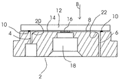
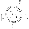
図1によれば、前記測定セルは、好ましくは非導電性材料で作られており経路4および経路6が組み入れられたベースブロック2を備えている。ベースブロック2は、シールエレメントおよび/またはスペーサーエレメント10がシールされる測定セルキャビティの周辺面8を含み、セルキャビティの輪郭は、図3に示されている。シールエレメントおよび/またはスペーサーエレメント10は、その上で支持されるアクリルガラスなどから作られたカバー12に対するスペーサーとして作用し、発光検出用の外部ホトセンサー用光学視認素子としての働きをする。
According to FIG. 1, the measuring cell comprises a
窓カバー12は、(図示されていない)ネジにより、前記ベースブロック2上に直接ネジ止めされている。前記ネジも、窓カバー12とベースブロック2のあいだでスペーサーとして作用する前記シールエレメントおよび/またはスペーサーエレメント10を貫通している(図2および図3中のネジ穴パターンを参照のこと)。
The
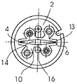
前記シールエレメントおよび/またはスペーサーエレメント10は、中央クリアランス13を持っており(図3を参照のこと)、その内部周縁の輪郭は、たとえば長いほぼ菱形の前記測定セルキャビティ14を定めており、その残りは、前記ベースブロック2の周辺面8および窓カバー12により区切られている。作用電極16は、ベースブロック2内の測定セルキャビティの周辺面内として構成される。対向電極は、前記作用電極16の反対側で、窓カバー12に置かれている(図示してない)。さらに、中空スペース18が、作用電極16の、窓カバー12側とは反対側に、ベースブロック2中に設けられており、前記中空スペース18は、B/F分離工程のあいだに磁性粒子をトラップするための磁石を収容している。
Said sealing element and / or
図1に見られるように、経路4、6は、測定セルキャビティの軸末端近くで、測定セルキャビティ14中に入り、前記経路4、6は、前記測定セルキャビティ中に流体を誘導するときに、ほぼ均一な流れのプロファイルを生じさせるために、また、流体流出口経路を経由して、前記測定セルキャビティ14から、流体のスムースな排出をするために、前記測定セルキャビティ14への遷移領域において、20、22で視認できる連続的に曲がったコースを持っている。
As can be seen in FIG. 1,
そのような測定セルにより、前記作用電極16上での磁性粒子の蓄積の精製品、およびそれによるマトリックス効果の抑制が、容易に出来るように、前記測定セルキャビティ中の流体および/または流体混合物を効率的にやり取りでき、また必要により、流体および/または流体混合物、特に洗浄流体を用いた前記測定セルキャビティ14の均一なフラッシングが可能である。
Such a measurement cell allows the fluid and / or fluid mixture in the measurement cell cavity to be easily refined in the accumulation of magnetic particles on the working
さらに、本発明の測定セルの機能は、その部品の組み立て変化を考慮して、より慣用性がある。 Furthermore, the function of the measuring cell of the present invention is more idiomatic in view of assembly changes of its parts.
2、10、12 測定セル筐体
4 流体流入口経路
6 流体流出口経路
8 側面
13 長楕円形経路
14 セルキャビティ
16 作用電極
18 中空スペース
20 曲線コース
2, 10, 12
Claims (7)
前記測定セルキャビティ上または内の少なくとも一つの作用電極(16)および対向電極と、
前記測定セルキャビティ(14)中のエレクトロルミネッセンス効果を観察するための測定セル筐体中の光学観察素子(12)と
を備えたエレクトロルミネッセンス測定を行うための測定セルであって、
前記測定セル筐体は、前記流体流入口経路(4)および前記流体流出口経路(6)によって画定され、かつ周辺面(8)の1つを用いて前記測定セルキャビティ(14)を区切るベースブロック(2)を含み、前記作用電極(16)は、前記測定セルキャビティの周辺面(8)上に設けられ、前記ベースブロック(2)は、前記作用電極(16)の、前記測定セルキャビティ(14)側とは反対側に磁石を収容するための中空のスペースを含んでおり、
前記流体流入口経路(4)は、流体を前記測定セルキャビティ(14)中に導入するとき、前記少なくとも一つの作用電極(16)の周辺でほぼ均一な流量プロファイルを発生させるように、前記測定セルキャビティにその末端で接続される前記流体流入口経路(4)が形成されるように、前記測定セルキャビティ(14)への遷移領域において少なくともほぼ連続した曲線コース(20)を持っていることを特徴とする測定セル。 Measurement cell cavity shape was oblong path (13) (14), in the direction crossing the longitudinal direction of the measurement cell cavity to the measurement cell cavity (14) in order to introduce fluid (14) A measuring cell housing (2, 10, 12) having an extending fluid inlet path (4) and a fluid outlet path (6) for discharging fluid from the measuring cell cavity (14);
At least one working electrode (16) and a counter electrode on or in the measurement cell cavity;
A measurement cell for performing an electroluminescence measurement comprising an optical observation element (12) in a measurement cell housing for observing an electroluminescence effect in the measurement cell cavity (14),
The measurement cell housing is a base defined by the fluid inlet path (4) and the fluid outlet path (6) and delimiting the measurement cell cavity (14) using one of the peripheral surfaces (8). Including a block (2), wherein the working electrode (16) is provided on a peripheral surface (8) of the measuring cell cavity, and the base block (2) is provided in the measuring cell cavity of the working electrode (16). (14) includes a hollow space for accommodating the magnet on the side opposite to the side,
It said fluid inlet path (4), when introducing fluid material into the measurement cell cavity (14), to generate a substantially uniform flow profile around the said at least one working electrode (16), wherein Having at least a substantially continuous curvilinear course (20) in the transition region to the measurement cell cavity (14) so that the fluid inlet channel (4) connected at its end to the measurement cell cavity is formed. A measuring cell characterized by that.
Applications Claiming Priority (2)
| Application Number | Priority Date | Filing Date | Title |
|---|---|---|---|
| EP06017810.0 | 2006-08-25 | ||
| EP06017810A EP1892524B1 (en) | 2006-08-25 | 2006-08-25 | Cell for conducting electrochemiluminescence measurements |
Publications (3)
| Publication Number | Publication Date |
|---|---|
| JP2008051813A JP2008051813A (en) | 2008-03-06 |
| JP2008051813A5 JP2008051813A5 (en) | 2013-05-16 |
| JP5265895B2 true JP5265895B2 (en) | 2013-08-14 |
Family
ID=37633622
Family Applications (1)
| Application Number | Title | Priority Date | Filing Date |
|---|---|---|---|
| JP2007213073A Active JP5265895B2 (en) | 2006-08-25 | 2007-08-17 | Cell for performing electroluminescence measurements |
Country Status (7)
| Country | Link |
|---|---|
| US (1) | US8940230B2 (en) |
| EP (1) | EP1892524B1 (en) |
| JP (1) | JP5265895B2 (en) |
| CN (1) | CN101131361B (en) |
| AT (1) | ATE530895T1 (en) |
| CA (1) | CA2598600C (en) |
| HK (1) | HK1118097A1 (en) |
Families Citing this family (10)
| Publication number | Priority date | Publication date | Assignee | Title |
|---|---|---|---|---|
| WO2011155489A1 (en) * | 2010-06-09 | 2011-12-15 | 株式会社日立ハイテクノロジーズ | Sample analysis device and sample analysis method |
| AU2011322704B2 (en) | 2010-10-25 | 2014-12-11 | F. Hoffmann-La Roche Ag | Use of signal enhancing compounds in electrochemiluminescence detection |
| EP2799871B1 (en) * | 2011-12-28 | 2021-10-13 | Hitachi High-Tech Corporation | Sample analysis device and sample analysis method |
| US9213043B2 (en) | 2012-05-15 | 2015-12-15 | Wellstat Diagnostics, Llc | Clinical diagnostic system including instrument and cartridge |
| US9625465B2 (en) | 2012-05-15 | 2017-04-18 | Defined Diagnostics, Llc | Clinical diagnostic systems |
| JP6239243B2 (en) | 2013-02-08 | 2017-11-29 | エフ.ホフマン−ラ ロシュ アーゲーF. Hoffmann−La Roche Aktiengesellschaft | Automatic analyzer |
| WO2016091755A1 (en) | 2014-12-08 | 2016-06-16 | F. Hoffmann-La Roche Ag | Method for measurement of vitamin d |
| CN105806828B (en) * | 2015-10-29 | 2019-05-14 | 北京联众泰克科技有限公司 | A kind of Electrogenerated chemiluminescent immunoassay system and its flow cell component |
| EP3426398B1 (en) | 2016-03-11 | 2024-01-24 | Roche Diagnostics GmbH | Branched-chain amines in electrochemiluminescence detection |
| JP6731815B2 (en) * | 2016-09-08 | 2020-07-29 | 株式会社日立ハイテク | Automatic analyzer |
Family Cites Families (12)
| Publication number | Priority date | Publication date | Assignee | Title |
|---|---|---|---|---|
| CA1325527C (en) * | 1988-04-28 | 1993-12-28 | Nicholas Leventis | Apparatus for conducting a plurality of simultaneous measurements of electrochemiluminescent phenomena |
| IL90105A (en) | 1988-04-29 | 1993-05-13 | Igen Inc | Method and apparatus for conducting electro- chemiluminescence measurements |
| US5068088A (en) | 1988-11-03 | 1991-11-26 | Igen, Inc. | Method and apparatus for conducting electrochemiluminescent measurements |
| US5746974A (en) | 1988-11-03 | 1998-05-05 | Igen International, Inc. | Apparatus for improved luminescence assays using particle concentration, electrochemical generation of chemiluminescence and chemiluminescence detection |
| DE4342942A1 (en) * | 1993-12-16 | 1995-06-22 | Boehringer Mannheim Gmbh | Device and method for generating optically detectable signals by applying electrical potentials to sample liquids |
| US5538687A (en) * | 1994-12-16 | 1996-07-23 | Behringer Mannheim Gmbh | Apparatus for generating optically detectable signals by applying electrical potentials to sample liquids |
| JPH09189662A (en) * | 1996-01-08 | 1997-07-22 | Hitachi Ltd | Electrochemical light emitting cell and electrochemical emission spectrometer |
| JP3641100B2 (en) * | 1997-05-27 | 2005-04-20 | ロッシュ ディアグノスティクス ゲゼルシャフト ミット ベシュレンクテル ハフツング | Electrochemiluminescence detection cell |
| DE19803528A1 (en) * | 1998-01-30 | 1999-08-05 | Roche Diagnostics Gmbh | Method for analyzing a sample using an electrochemiluminescence binding reaction test |
| JP2005241522A (en) * | 2004-02-27 | 2005-09-08 | Horiba Advanced Techno Co Ltd | Fluid analyzer |
| US20030175947A1 (en) * | 2001-11-05 | 2003-09-18 | Liu Robin Hui | Enhanced mixing in microfluidic devices |
| CN1323296C (en) * | 2004-07-05 | 2007-06-27 | 江苏省肿瘤医院 | Flow injection chemiluminescent immunity detecting pool for silicane cross-linked chitosan film base and process for preparing same |
-
2006
- 2006-08-25 AT AT06017810T patent/ATE530895T1/en active
- 2006-08-25 EP EP06017810A patent/EP1892524B1/en active Active
-
2007
- 2007-08-17 JP JP2007213073A patent/JP5265895B2/en active Active
- 2007-08-23 US US11/895,271 patent/US8940230B2/en active Active
- 2007-08-24 CA CA2598600A patent/CA2598600C/en active Active
- 2007-08-24 CN CN200710146851.7A patent/CN101131361B/en active Active
-
2008
- 2008-08-19 HK HK08109247.4A patent/HK1118097A1/en unknown
Also Published As
| Publication number | Publication date |
|---|---|
| CN101131361A (en) | 2008-02-27 |
| HK1118097A1 (en) | 2009-01-30 |
| JP2008051813A (en) | 2008-03-06 |
| US8940230B2 (en) | 2015-01-27 |
| EP1892524A1 (en) | 2008-02-27 |
| US20080047332A1 (en) | 2008-02-28 |
| EP1892524B1 (en) | 2011-10-26 |
| CA2598600C (en) | 2013-08-13 |
| CN101131361B (en) | 2010-09-29 |
| CA2598600A1 (en) | 2008-02-25 |
| ATE530895T1 (en) | 2011-11-15 |
Similar Documents
| Publication | Publication Date | Title |
|---|---|---|
| JP5265895B2 (en) | Cell for performing electroluminescence measurements | |
| JP2008051813A5 (en) | ||
| JP6878742B2 (en) | Assay system | |
| JP6130306B2 (en) | Rapid quantification of biomolecules and methods in selectively functionalized nanofluidic biosensors | |
| EP3059588B1 (en) | Method and device for detection and quantification of analytes | |
| JP6289379B2 (en) | Mechanical cleaning and measuring device for performing analysis | |
| US20150090591A1 (en) | Apparatus, systems, and methods for capillary electrophoresis | |
| JPH03503451A (en) | Method and apparatus for making electrochemiluminescence measurements | |
| US8975087B2 (en) | Longitudinal assay | |
| KR20140012933A (en) | Integrated carbon electrode chips for the electric excitation of lanthanide chelates, and analytical methods using these chips | |
| JP5685601B2 (en) | Nanofluidic biosensor and its utilization and method for rapid measurement of biomolecule interactions in solution | |
| KR101178014B1 (en) | A method for testing a liquid | |
| US8753493B2 (en) | Apparatus for measuring biomaterial and method for manufacturing same | |
| JP6502960B2 (en) | Gas exhaust system for nanofluid biosensors | |
| KR960018583A (en) | Immunoassay | |
| ATE520034T1 (en) | QUANTITATIVE ANALYSIS OF A BIOLOGICAL SAMPLE OF UNKNOWN QUANTITY | |
| US20060246603A1 (en) | Generation of chemiluminescence by hydrogen | |
| JP2010038596A (en) | Operation method of fluid handling device |
Legal Events
| Date | Code | Title | Description |
|---|---|---|---|
| A521 | Request for written amendment filed |
Free format text: JAPANESE INTERMEDIATE CODE: A821 Effective date: 20071106 |
|
| A621 | Written request for application examination |
Free format text: JAPANESE INTERMEDIATE CODE: A621 Effective date: 20100106 |
|
| RD03 | Notification of appointment of power of attorney |
Free format text: JAPANESE INTERMEDIATE CODE: A7423 Effective date: 20100525 |
|
| A131 | Notification of reasons for refusal |
Free format text: JAPANESE INTERMEDIATE CODE: A131 Effective date: 20120131 |
|
| A524 | Written submission of copy of amendment under article 19 pct |
Free format text: JAPANESE INTERMEDIATE CODE: A524 Effective date: 20120501 |
|
| A521 | Request for written amendment filed |
Free format text: JAPANESE INTERMEDIATE CODE: A821 Effective date: 20120501 |
|
| A02 | Decision of refusal |
Free format text: JAPANESE INTERMEDIATE CODE: A02 Effective date: 20121127 |
|
| A524 | Written submission of copy of amendment under article 19 pct |
Free format text: JAPANESE INTERMEDIATE CODE: A524 Effective date: 20130326 |
|
| A911 | Transfer to examiner for re-examination before appeal (zenchi) |
Free format text: JAPANESE INTERMEDIATE CODE: A911 Effective date: 20130402 |
|
| TRDD | Decision of grant or rejection written | ||
| A01 | Written decision to grant a patent or to grant a registration (utility model) |
Free format text: JAPANESE INTERMEDIATE CODE: A01 Effective date: 20130423 |
|
| A61 | First payment of annual fees (during grant procedure) |
Free format text: JAPANESE INTERMEDIATE CODE: A61 Effective date: 20130502 |
|
| R150 | Certificate of patent or registration of utility model |
Free format text: JAPANESE INTERMEDIATE CODE: R150 Ref document number: 5265895 Country of ref document: JP Free format text: JAPANESE INTERMEDIATE CODE: R150 |
|
| R250 | Receipt of annual fees |
Free format text: JAPANESE INTERMEDIATE CODE: R250 |
|
| R250 | Receipt of annual fees |
Free format text: JAPANESE INTERMEDIATE CODE: R250 |
|
| R250 | Receipt of annual fees |
Free format text: JAPANESE INTERMEDIATE CODE: R250 |
|
| R250 | Receipt of annual fees |
Free format text: JAPANESE INTERMEDIATE CODE: R250 |
|
| R250 | Receipt of annual fees |
Free format text: JAPANESE INTERMEDIATE CODE: R250 |
|
| R250 | Receipt of annual fees |
Free format text: JAPANESE INTERMEDIATE CODE: R250 |
|
| R250 | Receipt of annual fees |
Free format text: JAPANESE INTERMEDIATE CODE: R250 |
|
| R250 | Receipt of annual fees |
Free format text: JAPANESE INTERMEDIATE CODE: R250 |