JP5265833B2 - Method and apparatus for obtaining high production rates of thermal chemical reactions - Google Patents
Method and apparatus for obtaining high production rates of thermal chemical reactions Download PDFInfo
- Publication number
- JP5265833B2 JP5265833B2 JP2001554783A JP2001554783A JP5265833B2 JP 5265833 B2 JP5265833 B2 JP 5265833B2 JP 2001554783 A JP2001554783 A JP 2001554783A JP 2001554783 A JP2001554783 A JP 2001554783A JP 5265833 B2 JP5265833 B2 JP 5265833B2
- Authority
- JP
- Japan
- Prior art keywords
- reaction
- catalyst
- oxide
- chamber
- reaction chamber
- Prior art date
- Legal status (The legal status is an assumption and is not a legal conclusion. Google has not performed a legal analysis and makes no representation as to the accuracy of the status listed.)
- Expired - Fee Related
Links
Images


Classifications
-
- B—PERFORMING OPERATIONS; TRANSPORTING
- B01—PHYSICAL OR CHEMICAL PROCESSES OR APPARATUS IN GENERAL
- B01J—CHEMICAL OR PHYSICAL PROCESSES, e.g. CATALYSIS OR COLLOID CHEMISTRY; THEIR RELEVANT APPARATUS
- B01J19/00—Chemical, physical or physico-chemical processes in general; Their relevant apparatus
- B01J19/0093—Microreactors, e.g. miniaturised or microfabricated reactors
-
- B—PERFORMING OPERATIONS; TRANSPORTING
- B01—PHYSICAL OR CHEMICAL PROCESSES OR APPARATUS IN GENERAL
- B01J—CHEMICAL OR PHYSICAL PROCESSES, e.g. CATALYSIS OR COLLOID CHEMISTRY; THEIR RELEVANT APPARATUS
- B01J12/00—Chemical processes in general for reacting gaseous media with gaseous media; Apparatus specially adapted therefor
- B01J12/007—Chemical processes in general for reacting gaseous media with gaseous media; Apparatus specially adapted therefor in the presence of catalytically active bodies, e.g. porous plates
-
- B—PERFORMING OPERATIONS; TRANSPORTING
- B01—PHYSICAL OR CHEMICAL PROCESSES OR APPARATUS IN GENERAL
- B01J—CHEMICAL OR PHYSICAL PROCESSES, e.g. CATALYSIS OR COLLOID CHEMISTRY; THEIR RELEVANT APPARATUS
- B01J19/00—Chemical, physical or physico-chemical processes in general; Their relevant apparatus
- B01J19/24—Stationary reactors without moving elements inside
- B01J19/248—Reactors comprising multiple separated flow channels
- B01J19/249—Plate-type reactors
-
- B—PERFORMING OPERATIONS; TRANSPORTING
- B01—PHYSICAL OR CHEMICAL PROCESSES OR APPARATUS IN GENERAL
- B01J—CHEMICAL OR PHYSICAL PROCESSES, e.g. CATALYSIS OR COLLOID CHEMISTRY; THEIR RELEVANT APPARATUS
- B01J8/00—Chemical or physical processes in general, conducted in the presence of fluids and solid particles; Apparatus for such processes
- B01J8/02—Chemical or physical processes in general, conducted in the presence of fluids and solid particles; Apparatus for such processes with stationary particles, e.g. in fixed beds
- B01J8/0285—Heating or cooling the reactor
-
- B—PERFORMING OPERATIONS; TRANSPORTING
- B01—PHYSICAL OR CHEMICAL PROCESSES OR APPARATUS IN GENERAL
- B01J—CHEMICAL OR PHYSICAL PROCESSES, e.g. CATALYSIS OR COLLOID CHEMISTRY; THEIR RELEVANT APPARATUS
- B01J8/00—Chemical or physical processes in general, conducted in the presence of fluids and solid particles; Apparatus for such processes
- B01J8/02—Chemical or physical processes in general, conducted in the presence of fluids and solid particles; Apparatus for such processes with stationary particles, e.g. in fixed beds
- B01J8/06—Chemical or physical processes in general, conducted in the presence of fluids and solid particles; Apparatus for such processes with stationary particles, e.g. in fixed beds in tube reactors; the solid particles being arranged in tubes
- B01J8/067—Heating or cooling the reactor
-
- C—CHEMISTRY; METALLURGY
- C01—INORGANIC CHEMISTRY
- C01B—NON-METALLIC ELEMENTS; COMPOUNDS THEREOF; METALLOIDS OR COMPOUNDS THEREOF NOT COVERED BY SUBCLASS C01C
- C01B3/00—Hydrogen; Gaseous mixtures containing hydrogen; Separation of hydrogen from mixtures containing it; Purification of hydrogen
- C01B3/02—Production of hydrogen or of gaseous mixtures containing a substantial proportion of hydrogen
- C01B3/06—Production of hydrogen or of gaseous mixtures containing a substantial proportion of hydrogen by reaction of inorganic compounds containing electro-positively bound hydrogen, e.g. water, acids, bases, ammonia, with inorganic reducing agents
- C01B3/12—Production of hydrogen or of gaseous mixtures containing a substantial proportion of hydrogen by reaction of inorganic compounds containing electro-positively bound hydrogen, e.g. water, acids, bases, ammonia, with inorganic reducing agents by reaction of water vapour with carbon monoxide
- C01B3/16—Production of hydrogen or of gaseous mixtures containing a substantial proportion of hydrogen by reaction of inorganic compounds containing electro-positively bound hydrogen, e.g. water, acids, bases, ammonia, with inorganic reducing agents by reaction of water vapour with carbon monoxide using catalysts
-
- C—CHEMISTRY; METALLURGY
- C01—INORGANIC CHEMISTRY
- C01B—NON-METALLIC ELEMENTS; COMPOUNDS THEREOF; METALLOIDS OR COMPOUNDS THEREOF NOT COVERED BY SUBCLASS C01C
- C01B3/00—Hydrogen; Gaseous mixtures containing hydrogen; Separation of hydrogen from mixtures containing it; Purification of hydrogen
- C01B3/02—Production of hydrogen or of gaseous mixtures containing a substantial proportion of hydrogen
- C01B3/32—Production of hydrogen or of gaseous mixtures containing a substantial proportion of hydrogen by reaction of gaseous or liquid organic compounds with gasifying agents, e.g. water, carbon dioxide, air
- C01B3/34—Production of hydrogen or of gaseous mixtures containing a substantial proportion of hydrogen by reaction of gaseous or liquid organic compounds with gasifying agents, e.g. water, carbon dioxide, air by reaction of hydrocarbons with gasifying agents
- C01B3/38—Production of hydrogen or of gaseous mixtures containing a substantial proportion of hydrogen by reaction of gaseous or liquid organic compounds with gasifying agents, e.g. water, carbon dioxide, air by reaction of hydrocarbons with gasifying agents using catalysts
- C01B3/384—Production of hydrogen or of gaseous mixtures containing a substantial proportion of hydrogen by reaction of gaseous or liquid organic compounds with gasifying agents, e.g. water, carbon dioxide, air by reaction of hydrocarbons with gasifying agents using catalysts the catalyst being continuously externally heated
-
- C—CHEMISTRY; METALLURGY
- C01—INORGANIC CHEMISTRY
- C01B—NON-METALLIC ELEMENTS; COMPOUNDS THEREOF; METALLOIDS OR COMPOUNDS THEREOF NOT COVERED BY SUBCLASS C01C
- C01B3/00—Hydrogen; Gaseous mixtures containing hydrogen; Separation of hydrogen from mixtures containing it; Purification of hydrogen
- C01B3/02—Production of hydrogen or of gaseous mixtures containing a substantial proportion of hydrogen
- C01B3/32—Production of hydrogen or of gaseous mixtures containing a substantial proportion of hydrogen by reaction of gaseous or liquid organic compounds with gasifying agents, e.g. water, carbon dioxide, air
- C01B3/34—Production of hydrogen or of gaseous mixtures containing a substantial proportion of hydrogen by reaction of gaseous or liquid organic compounds with gasifying agents, e.g. water, carbon dioxide, air by reaction of hydrocarbons with gasifying agents
- C01B3/48—Production of hydrogen or of gaseous mixtures containing a substantial proportion of hydrogen by reaction of gaseous or liquid organic compounds with gasifying agents, e.g. water, carbon dioxide, air by reaction of hydrocarbons with gasifying agents followed by reaction of water vapour with carbon monoxide
-
- F—MECHANICAL ENGINEERING; LIGHTING; HEATING; WEAPONS; BLASTING
- F28—HEAT EXCHANGE IN GENERAL
- F28D—HEAT-EXCHANGE APPARATUS, NOT PROVIDED FOR IN ANOTHER SUBCLASS, IN WHICH THE HEAT-EXCHANGE MEDIA DO NOT COME INTO DIRECT CONTACT
- F28D7/00—Heat-exchange apparatus having stationary tubular conduit assemblies for both heat-exchange media, the media being in contact with different sides of a conduit wall
-
- B—PERFORMING OPERATIONS; TRANSPORTING
- B01—PHYSICAL OR CHEMICAL PROCESSES OR APPARATUS IN GENERAL
- B01J—CHEMICAL OR PHYSICAL PROCESSES, e.g. CATALYSIS OR COLLOID CHEMISTRY; THEIR RELEVANT APPARATUS
- B01J2208/00—Processes carried out in the presence of solid particles; Reactors therefor
- B01J2208/00008—Controlling the process
- B01J2208/00017—Controlling the temperature
- B01J2208/00106—Controlling the temperature by indirect heat exchange
- B01J2208/00168—Controlling the temperature by indirect heat exchange with heat exchange elements outside the bed of solid particles
- B01J2208/00194—Tubes
-
- B—PERFORMING OPERATIONS; TRANSPORTING
- B01—PHYSICAL OR CHEMICAL PROCESSES OR APPARATUS IN GENERAL
- B01J—CHEMICAL OR PHYSICAL PROCESSES, e.g. CATALYSIS OR COLLOID CHEMISTRY; THEIR RELEVANT APPARATUS
- B01J2208/00—Processes carried out in the presence of solid particles; Reactors therefor
- B01J2208/00008—Controlling the process
- B01J2208/00017—Controlling the temperature
- B01J2208/00106—Controlling the temperature by indirect heat exchange
- B01J2208/00168—Controlling the temperature by indirect heat exchange with heat exchange elements outside the bed of solid particles
- B01J2208/00212—Plates; Jackets; Cylinders
-
- B—PERFORMING OPERATIONS; TRANSPORTING
- B01—PHYSICAL OR CHEMICAL PROCESSES OR APPARATUS IN GENERAL
- B01J—CHEMICAL OR PHYSICAL PROCESSES, e.g. CATALYSIS OR COLLOID CHEMISTRY; THEIR RELEVANT APPARATUS
- B01J2208/00—Processes carried out in the presence of solid particles; Reactors therefor
- B01J2208/00008—Controlling the process
- B01J2208/00017—Controlling the temperature
- B01J2208/00106—Controlling the temperature by indirect heat exchange
- B01J2208/00309—Controlling the temperature by indirect heat exchange with two or more reactions in heat exchange with each other, such as an endothermic reaction in heat exchange with an exothermic reaction
-
- B—PERFORMING OPERATIONS; TRANSPORTING
- B01—PHYSICAL OR CHEMICAL PROCESSES OR APPARATUS IN GENERAL
- B01J—CHEMICAL OR PHYSICAL PROCESSES, e.g. CATALYSIS OR COLLOID CHEMISTRY; THEIR RELEVANT APPARATUS
- B01J2219/00—Chemical, physical or physico-chemical processes in general; Their relevant apparatus
- B01J2219/00781—Aspects relating to microreactors
- B01J2219/00783—Laminate assemblies, i.e. the reactor comprising a stack of plates
-
- B—PERFORMING OPERATIONS; TRANSPORTING
- B01—PHYSICAL OR CHEMICAL PROCESSES OR APPARATUS IN GENERAL
- B01J—CHEMICAL OR PHYSICAL PROCESSES, e.g. CATALYSIS OR COLLOID CHEMISTRY; THEIR RELEVANT APPARATUS
- B01J2219/00—Chemical, physical or physico-chemical processes in general; Their relevant apparatus
- B01J2219/00781—Aspects relating to microreactors
- B01J2219/00788—Three-dimensional assemblies, i.e. the reactor comprising a form other than a stack of plates
-
- B—PERFORMING OPERATIONS; TRANSPORTING
- B01—PHYSICAL OR CHEMICAL PROCESSES OR APPARATUS IN GENERAL
- B01J—CHEMICAL OR PHYSICAL PROCESSES, e.g. CATALYSIS OR COLLOID CHEMISTRY; THEIR RELEVANT APPARATUS
- B01J2219/00—Chemical, physical or physico-chemical processes in general; Their relevant apparatus
- B01J2219/00781—Aspects relating to microreactors
- B01J2219/00819—Materials of construction
- B01J2219/00822—Metal
-
- B—PERFORMING OPERATIONS; TRANSPORTING
- B01—PHYSICAL OR CHEMICAL PROCESSES OR APPARATUS IN GENERAL
- B01J—CHEMICAL OR PHYSICAL PROCESSES, e.g. CATALYSIS OR COLLOID CHEMISTRY; THEIR RELEVANT APPARATUS
- B01J2219/00—Chemical, physical or physico-chemical processes in general; Their relevant apparatus
- B01J2219/00781—Aspects relating to microreactors
- B01J2219/00819—Materials of construction
- B01J2219/00835—Comprising catalytically active material
-
- B—PERFORMING OPERATIONS; TRANSPORTING
- B01—PHYSICAL OR CHEMICAL PROCESSES OR APPARATUS IN GENERAL
- B01J—CHEMICAL OR PHYSICAL PROCESSES, e.g. CATALYSIS OR COLLOID CHEMISTRY; THEIR RELEVANT APPARATUS
- B01J2219/00—Chemical, physical or physico-chemical processes in general; Their relevant apparatus
- B01J2219/00781—Aspects relating to microreactors
- B01J2219/00851—Additional features
- B01J2219/00858—Aspects relating to the size of the reactor
- B01J2219/0086—Dimensions of the flow channels
-
- B—PERFORMING OPERATIONS; TRANSPORTING
- B01—PHYSICAL OR CHEMICAL PROCESSES OR APPARATUS IN GENERAL
- B01J—CHEMICAL OR PHYSICAL PROCESSES, e.g. CATALYSIS OR COLLOID CHEMISTRY; THEIR RELEVANT APPARATUS
- B01J2219/00—Chemical, physical or physico-chemical processes in general; Their relevant apparatus
- B01J2219/00781—Aspects relating to microreactors
- B01J2219/00873—Heat exchange
-
- B—PERFORMING OPERATIONS; TRANSPORTING
- B01—PHYSICAL OR CHEMICAL PROCESSES OR APPARATUS IN GENERAL
- B01J—CHEMICAL OR PHYSICAL PROCESSES, e.g. CATALYSIS OR COLLOID CHEMISTRY; THEIR RELEVANT APPARATUS
- B01J2219/00—Chemical, physical or physico-chemical processes in general; Their relevant apparatus
- B01J2219/00781—Aspects relating to microreactors
- B01J2219/0095—Control aspects
- B01J2219/00984—Residence time
-
- B—PERFORMING OPERATIONS; TRANSPORTING
- B01—PHYSICAL OR CHEMICAL PROCESSES OR APPARATUS IN GENERAL
- B01J—CHEMICAL OR PHYSICAL PROCESSES, e.g. CATALYSIS OR COLLOID CHEMISTRY; THEIR RELEVANT APPARATUS
- B01J2219/00—Chemical, physical or physico-chemical processes in general; Their relevant apparatus
- B01J2219/24—Stationary reactors without moving elements inside
- B01J2219/2401—Reactors comprising multiple separate flow channels
- B01J2219/245—Plate-type reactors
- B01J2219/2451—Geometry of the reactor
- B01J2219/2453—Plates arranged in parallel
-
- B—PERFORMING OPERATIONS; TRANSPORTING
- B01—PHYSICAL OR CHEMICAL PROCESSES OR APPARATUS IN GENERAL
- B01J—CHEMICAL OR PHYSICAL PROCESSES, e.g. CATALYSIS OR COLLOID CHEMISTRY; THEIR RELEVANT APPARATUS
- B01J2219/00—Chemical, physical or physico-chemical processes in general; Their relevant apparatus
- B01J2219/24—Stationary reactors without moving elements inside
- B01J2219/2401—Reactors comprising multiple separate flow channels
- B01J2219/245—Plate-type reactors
- B01J2219/2451—Geometry of the reactor
- B01J2219/2454—Plates arranged concentrically
-
- B—PERFORMING OPERATIONS; TRANSPORTING
- B01—PHYSICAL OR CHEMICAL PROCESSES OR APPARATUS IN GENERAL
- B01J—CHEMICAL OR PHYSICAL PROCESSES, e.g. CATALYSIS OR COLLOID CHEMISTRY; THEIR RELEVANT APPARATUS
- B01J2219/00—Chemical, physical or physico-chemical processes in general; Their relevant apparatus
- B01J2219/24—Stationary reactors without moving elements inside
- B01J2219/2401—Reactors comprising multiple separate flow channels
- B01J2219/245—Plate-type reactors
- B01J2219/2451—Geometry of the reactor
- B01J2219/2456—Geometry of the plates
- B01J2219/2458—Flat plates, i.e. plates which are not corrugated or otherwise structured, e.g. plates with cylindrical shape
-
- B—PERFORMING OPERATIONS; TRANSPORTING
- B01—PHYSICAL OR CHEMICAL PROCESSES OR APPARATUS IN GENERAL
- B01J—CHEMICAL OR PHYSICAL PROCESSES, e.g. CATALYSIS OR COLLOID CHEMISTRY; THEIR RELEVANT APPARATUS
- B01J2219/00—Chemical, physical or physico-chemical processes in general; Their relevant apparatus
- B01J2219/24—Stationary reactors without moving elements inside
- B01J2219/2401—Reactors comprising multiple separate flow channels
- B01J2219/245—Plate-type reactors
- B01J2219/2461—Heat exchange aspects
- B01J2219/2465—Two reactions in indirect heat exchange with each other
-
- B—PERFORMING OPERATIONS; TRANSPORTING
- B01—PHYSICAL OR CHEMICAL PROCESSES OR APPARATUS IN GENERAL
- B01J—CHEMICAL OR PHYSICAL PROCESSES, e.g. CATALYSIS OR COLLOID CHEMISTRY; THEIR RELEVANT APPARATUS
- B01J2219/00—Chemical, physical or physico-chemical processes in general; Their relevant apparatus
- B01J2219/24—Stationary reactors without moving elements inside
- B01J2219/2401—Reactors comprising multiple separate flow channels
- B01J2219/245—Plate-type reactors
- B01J2219/2476—Construction materials
- B01J2219/2477—Construction materials of the catalysts
- B01J2219/2481—Catalysts in granular from between plates
-
- B—PERFORMING OPERATIONS; TRANSPORTING
- B01—PHYSICAL OR CHEMICAL PROCESSES OR APPARATUS IN GENERAL
- B01J—CHEMICAL OR PHYSICAL PROCESSES, e.g. CATALYSIS OR COLLOID CHEMISTRY; THEIR RELEVANT APPARATUS
- B01J2219/00—Chemical, physical or physico-chemical processes in general; Their relevant apparatus
- B01J2219/24—Stationary reactors without moving elements inside
- B01J2219/2401—Reactors comprising multiple separate flow channels
- B01J2219/245—Plate-type reactors
- B01J2219/2491—Other constructional details
- B01J2219/2497—Size aspects, i.e. concrete sizes are being mentioned in the classified document
-
- C—CHEMISTRY; METALLURGY
- C01—INORGANIC CHEMISTRY
- C01B—NON-METALLIC ELEMENTS; COMPOUNDS THEREOF; METALLOIDS OR COMPOUNDS THEREOF NOT COVERED BY SUBCLASS C01C
- C01B2203/00—Integrated processes for the production of hydrogen or synthesis gas
- C01B2203/02—Processes for making hydrogen or synthesis gas
- C01B2203/0205—Processes for making hydrogen or synthesis gas containing a reforming step
- C01B2203/0227—Processes for making hydrogen or synthesis gas containing a reforming step containing a catalytic reforming step
- C01B2203/0233—Processes for making hydrogen or synthesis gas containing a reforming step containing a catalytic reforming step the reforming step being a steam reforming step
-
- C—CHEMISTRY; METALLURGY
- C01—INORGANIC CHEMISTRY
- C01B—NON-METALLIC ELEMENTS; COMPOUNDS THEREOF; METALLOIDS OR COMPOUNDS THEREOF NOT COVERED BY SUBCLASS C01C
- C01B2203/00—Integrated processes for the production of hydrogen or synthesis gas
- C01B2203/02—Processes for making hydrogen or synthesis gas
- C01B2203/0283—Processes for making hydrogen or synthesis gas containing a CO-shift step, i.e. a water gas shift step
-
- C—CHEMISTRY; METALLURGY
- C01—INORGANIC CHEMISTRY
- C01B—NON-METALLIC ELEMENTS; COMPOUNDS THEREOF; METALLOIDS OR COMPOUNDS THEREOF NOT COVERED BY SUBCLASS C01C
- C01B2203/00—Integrated processes for the production of hydrogen or synthesis gas
- C01B2203/04—Integrated processes for the production of hydrogen or synthesis gas containing a purification step for the hydrogen or the synthesis gas
- C01B2203/0465—Composition of the impurity
- C01B2203/0495—Composition of the impurity the impurity being water
-
- C—CHEMISTRY; METALLURGY
- C01—INORGANIC CHEMISTRY
- C01B—NON-METALLIC ELEMENTS; COMPOUNDS THEREOF; METALLOIDS OR COMPOUNDS THEREOF NOT COVERED BY SUBCLASS C01C
- C01B2203/00—Integrated processes for the production of hydrogen or synthesis gas
- C01B2203/06—Integration with other chemical processes
- C01B2203/066—Integration with other chemical processes with fuel cells
-
- C—CHEMISTRY; METALLURGY
- C01—INORGANIC CHEMISTRY
- C01B—NON-METALLIC ELEMENTS; COMPOUNDS THEREOF; METALLOIDS OR COMPOUNDS THEREOF NOT COVERED BY SUBCLASS C01C
- C01B2203/00—Integrated processes for the production of hydrogen or synthesis gas
- C01B2203/08—Methods of heating or cooling
- C01B2203/0805—Methods of heating the process for making hydrogen or synthesis gas
- C01B2203/0811—Methods of heating the process for making hydrogen or synthesis gas by combustion of fuel
-
- C—CHEMISTRY; METALLURGY
- C01—INORGANIC CHEMISTRY
- C01B—NON-METALLIC ELEMENTS; COMPOUNDS THEREOF; METALLOIDS OR COMPOUNDS THEREOF NOT COVERED BY SUBCLASS C01C
- C01B2203/00—Integrated processes for the production of hydrogen or synthesis gas
- C01B2203/08—Methods of heating or cooling
- C01B2203/0805—Methods of heating the process for making hydrogen or synthesis gas
- C01B2203/0833—Heating by indirect heat exchange with hot fluids, other than combustion gases, product gases or non-combustive exothermic reaction product gases
-
- C—CHEMISTRY; METALLURGY
- C01—INORGANIC CHEMISTRY
- C01B—NON-METALLIC ELEMENTS; COMPOUNDS THEREOF; METALLOIDS OR COMPOUNDS THEREOF NOT COVERED BY SUBCLASS C01C
- C01B2203/00—Integrated processes for the production of hydrogen or synthesis gas
- C01B2203/10—Catalysts for performing the hydrogen forming reactions
- C01B2203/1005—Arrangement or shape of catalyst
- C01B2203/1023—Catalysts in the form of a monolith or honeycomb
-
- C—CHEMISTRY; METALLURGY
- C01—INORGANIC CHEMISTRY
- C01B—NON-METALLIC ELEMENTS; COMPOUNDS THEREOF; METALLOIDS OR COMPOUNDS THEREOF NOT COVERED BY SUBCLASS C01C
- C01B2203/00—Integrated processes for the production of hydrogen or synthesis gas
- C01B2203/10—Catalysts for performing the hydrogen forming reactions
- C01B2203/1005—Arrangement or shape of catalyst
- C01B2203/1029—Catalysts in the form of a foam
-
- C—CHEMISTRY; METALLURGY
- C01—INORGANIC CHEMISTRY
- C01B—NON-METALLIC ELEMENTS; COMPOUNDS THEREOF; METALLOIDS OR COMPOUNDS THEREOF NOT COVERED BY SUBCLASS C01C
- C01B2203/00—Integrated processes for the production of hydrogen or synthesis gas
- C01B2203/10—Catalysts for performing the hydrogen forming reactions
- C01B2203/1041—Composition of the catalyst
- C01B2203/1047—Group VIII metal catalysts
- C01B2203/1052—Nickel or cobalt catalysts
- C01B2203/1058—Nickel catalysts
-
- C—CHEMISTRY; METALLURGY
- C01—INORGANIC CHEMISTRY
- C01B—NON-METALLIC ELEMENTS; COMPOUNDS THEREOF; METALLOIDS OR COMPOUNDS THEREOF NOT COVERED BY SUBCLASS C01C
- C01B2203/00—Integrated processes for the production of hydrogen or synthesis gas
- C01B2203/10—Catalysts for performing the hydrogen forming reactions
- C01B2203/1041—Composition of the catalyst
- C01B2203/1047—Group VIII metal catalysts
- C01B2203/1064—Platinum group metal catalysts
-
- C—CHEMISTRY; METALLURGY
- C01—INORGANIC CHEMISTRY
- C01B—NON-METALLIC ELEMENTS; COMPOUNDS THEREOF; METALLOIDS OR COMPOUNDS THEREOF NOT COVERED BY SUBCLASS C01C
- C01B2203/00—Integrated processes for the production of hydrogen or synthesis gas
- C01B2203/10—Catalysts for performing the hydrogen forming reactions
- C01B2203/1041—Composition of the catalyst
- C01B2203/1082—Composition of support materials
-
- C—CHEMISTRY; METALLURGY
- C01—INORGANIC CHEMISTRY
- C01B—NON-METALLIC ELEMENTS; COMPOUNDS THEREOF; METALLOIDS OR COMPOUNDS THEREOF NOT COVERED BY SUBCLASS C01C
- C01B2203/00—Integrated processes for the production of hydrogen or synthesis gas
- C01B2203/12—Feeding the process for making hydrogen or synthesis gas
- C01B2203/1205—Composition of the feed
- C01B2203/1211—Organic compounds or organic mixtures used in the process for making hydrogen or synthesis gas
- C01B2203/1235—Hydrocarbons
- C01B2203/1241—Natural gas or methane
-
- C—CHEMISTRY; METALLURGY
- C01—INORGANIC CHEMISTRY
- C01B—NON-METALLIC ELEMENTS; COMPOUNDS THEREOF; METALLOIDS OR COMPOUNDS THEREOF NOT COVERED BY SUBCLASS C01C
- C01B2203/00—Integrated processes for the production of hydrogen or synthesis gas
- C01B2203/12—Feeding the process for making hydrogen or synthesis gas
- C01B2203/1205—Composition of the feed
- C01B2203/1211—Organic compounds or organic mixtures used in the process for making hydrogen or synthesis gas
- C01B2203/1235—Hydrocarbons
- C01B2203/1247—Higher hydrocarbons
-
- C—CHEMISTRY; METALLURGY
- C01—INORGANIC CHEMISTRY
- C01B—NON-METALLIC ELEMENTS; COMPOUNDS THEREOF; METALLOIDS OR COMPOUNDS THEREOF NOT COVERED BY SUBCLASS C01C
- C01B2203/00—Integrated processes for the production of hydrogen or synthesis gas
- C01B2203/12—Feeding the process for making hydrogen or synthesis gas
- C01B2203/1288—Evaporation of one or more of the different feed components
-
- C—CHEMISTRY; METALLURGY
- C01—INORGANIC CHEMISTRY
- C01B—NON-METALLIC ELEMENTS; COMPOUNDS THEREOF; METALLOIDS OR COMPOUNDS THEREOF NOT COVERED BY SUBCLASS C01C
- C01B2203/00—Integrated processes for the production of hydrogen or synthesis gas
- C01B2203/16—Controlling the process
- C01B2203/1614—Controlling the temperature
- C01B2203/1619—Measuring the temperature
-
- C—CHEMISTRY; METALLURGY
- C01—INORGANIC CHEMISTRY
- C01B—NON-METALLIC ELEMENTS; COMPOUNDS THEREOF; METALLOIDS OR COMPOUNDS THEREOF NOT COVERED BY SUBCLASS C01C
- C01B2203/00—Integrated processes for the production of hydrogen or synthesis gas
- C01B2203/16—Controlling the process
- C01B2203/1628—Controlling the pressure
- C01B2203/1633—Measuring the pressure
-
- C—CHEMISTRY; METALLURGY
- C01—INORGANIC CHEMISTRY
- C01B—NON-METALLIC ELEMENTS; COMPOUNDS THEREOF; METALLOIDS OR COMPOUNDS THEREOF NOT COVERED BY SUBCLASS C01C
- C01B2203/00—Integrated processes for the production of hydrogen or synthesis gas
- C01B2203/16—Controlling the process
- C01B2203/1642—Controlling the product
- C01B2203/1647—Controlling the amount of the product
- C01B2203/1652—Measuring the amount of product
-
- C—CHEMISTRY; METALLURGY
- C01—INORGANIC CHEMISTRY
- C01B—NON-METALLIC ELEMENTS; COMPOUNDS THEREOF; METALLOIDS OR COMPOUNDS THEREOF NOT COVERED BY SUBCLASS C01C
- C01B2203/00—Integrated processes for the production of hydrogen or synthesis gas
- C01B2203/16—Controlling the process
- C01B2203/1642—Controlling the product
- C01B2203/1671—Controlling the composition of the product
- C01B2203/1676—Measuring the composition of the product
-
- C—CHEMISTRY; METALLURGY
- C01—INORGANIC CHEMISTRY
- C01B—NON-METALLIC ELEMENTS; COMPOUNDS THEREOF; METALLOIDS OR COMPOUNDS THEREOF NOT COVERED BY SUBCLASS C01C
- C01B2203/00—Integrated processes for the production of hydrogen or synthesis gas
- C01B2203/16—Controlling the process
- C01B2203/169—Controlling the feed
-
- Y—GENERAL TAGGING OF NEW TECHNOLOGICAL DEVELOPMENTS; GENERAL TAGGING OF CROSS-SECTIONAL TECHNOLOGIES SPANNING OVER SEVERAL SECTIONS OF THE IPC; TECHNICAL SUBJECTS COVERED BY FORMER USPC CROSS-REFERENCE ART COLLECTIONS [XRACs] AND DIGESTS
- Y02—TECHNOLOGIES OR APPLICATIONS FOR MITIGATION OR ADAPTATION AGAINST CLIMATE CHANGE
- Y02P—CLIMATE CHANGE MITIGATION TECHNOLOGIES IN THE PRODUCTION OR PROCESSING OF GOODS
- Y02P20/00—Technologies relating to chemical industry
- Y02P20/50—Improvements relating to the production of bulk chemicals
- Y02P20/52—Improvements relating to the production of bulk chemicals using catalysts, e.g. selective catalysts
Abstract
Description
本発明の属する技術分野
本発明は、熱的化学反応のための方法および装置に関する。この方法および装置は、熱的化学反応に対し大きい反応速度を提供することができる。The present invention relates to a method and apparatus for thermal chemical reactions. This method and apparatus can provide a high reaction rate for thermal chemical reactions.
本発明の背景
熱的化学反応とは、熱を生成する(発熱)または熱を消費する(吸熱)化学反応である。熱的化学反応の例に含まれるのは、水蒸気改質、水性ガス・シフト反応および燃焼のような炭化水素転化反応である。これらの良く知られた反応は、通常、触媒の存在下、約1300℃までの温度で行われる。熱的化学反応の固有速度は、その反応容器と、熱溜め(thermal sink)、熱源または熱的環境との間の熱伝達速度より遥かに速いことがあるので、現実の生成物生成速度(観測される速度)は、その反応の固有速度より遅い。固有速度とは、生成物が、触媒表面で理論的に生成され得る速度を意味する。BACKGROUND OF THE INVENTION Thermal chemical reactions are chemical reactions that generate heat (exotherm) or consume heat (endothermic). Examples of thermal chemical reactions include hydrocarbon conversion reactions such as steam reforming, water gas shift reactions and combustion. These well-known reactions are usually performed at temperatures up to about 1300 ° C. in the presence of a catalyst. The intrinsic rate of a thermal chemical reaction can be much faster than the rate of heat transfer between the reaction vessel and a thermal sink, heat source or thermal environment, so that the actual product production rate (observation) Is slower than the intrinsic rate of the reaction. By intrinsic rate is meant the rate at which the product can theoretically be produced on the catalyst surface.
生成速度が制約されるのは、通常の熱的化学反応容器中では、普通、数秒から数分である長い滞留時間の結果である可能性がある。普通定義されているように、滞留時間は、その反応ゾーンの容積を、その反応系の温度と圧力における反応物の入口での体積流速で割った値に等しい。この反応ゾーンとは、反応物と生成物がその中を流れる触媒と周囲の領域の総体積である。 The rate of production may be limited as a result of long residence times, usually seconds to minutes, in normal thermal chemical reactors. As commonly defined, the residence time is equal to the volume of the reaction zone divided by the volume flow rate at the reactant inlet at the temperature and pressure of the reaction system. This reaction zone is the total volume of the catalyst and surrounding area through which reactants and products flow.
このような制約された生成速度の一例は、固定層反応器中で普通行われる水性ガス・シフト反応で見られる。この水性ガス・シフト反応では、一酸化炭素と水が二酸化炭素と水素に転化される。通常、この反応は、固定層反応器中で行われた場合、マルチ秒の滞留時間を要する [速度論的障害(kinetic impediment)] 。理論的速度論は、理論的には、ミリ秒の桁の滞留時間を得ることが可能であることを示唆する。常用の反応器では、二つの速度論的遅延態様が存在する。第1は、触媒を担持する多孔性ペレット中へ、およびペレットから、反応物が拡散する時の拡散制約であり、第2は、触媒担体の熱伝達パラメータ(熱伝導率および長さ)と、反応器の全体としての幾何学的特徴(形状、サイズ、および外部熱交換器までの距離)との組合せである熱伝達制約である。水性ガス・シフト反応は、燃料電池を使用することにより、分配エネルギーの生産を支えるマルチ‐反応器型燃料加工系にとって基本的に重要であるから、より小さくて、より速い水性ガス・シフト反応器に対する需要が存在する。 An example of such a constrained production rate is found in the water gas shift reaction normally performed in a fixed bed reactor. In this water gas shift reaction, carbon monoxide and water are converted to carbon dioxide and hydrogen. This reaction usually requires a multisecond residence time when performed in a fixed bed reactor [kinetic impediment]. Theoretical kinetics suggests that it is theoretically possible to obtain residence times on the order of milliseconds. In conventional reactors, there are two kinetic delay modes. The first is the diffusion constraint when the reactants diffuse into and out of the porous pellets carrying the catalyst, and the second is the heat transfer parameters (thermal conductivity and length) of the catalyst support, Heat transfer constraints that are a combination of the overall geometric features of the reactor (shape, size, and distance to the external heat exchanger). Because water gas shift reactions are fundamentally important to multi-reactor fuel processing systems that support the production of distributed energy by using fuel cells, smaller and faster water gas shift reactors There is a demand for.
熱的化学反応のもう一つの例は、Adris,A.,Pruden,B.,Lim,C.,J.Grace によりCanadian Journal of Chemical Engineering,74,177-186(1996) “On the reported attempts to radically improve the performance of the steam methane reforming reactor ”(“水蒸気メタン改質用反応器の実用性能を基本的に改善するために報告された試み”)に報告されているような、平均滞留時間が数秒で、触媒有効係数が0.01〜0.05で、合成ガスを生産する常用のメタン水蒸気改質反応器中での反応である。典型的な工業的操業では、コークスの生成を避けるために、メタン:水蒸気比は3:1 で運転される。この吸熱反応用反応容器と熱源との間の熱伝達を改善するための努力は、製品生産速度を、僅かに向上させただけであった。 Another example of a thermal chemical reaction is Adris, A., Pruden, B., Lim, C., J. Grace, Canadian Journal of Chemical Engineering, 74, 177-186 (1996) “On the reported attempts to radically improve. With an average residence time of a few seconds, as reported in the performance of the steam methane reforming reactor "(" A reported effort to fundamentally improve the practical performance of a steam methane reforming reactor ") This is a reaction in a conventional methane steam reforming reactor having a catalyst effectiveness factor of 0.01 to 0.05 and producing synthesis gas. In a typical industrial operation, a methane: steam ratio is operated at 3: 1 to avoid coke formation. Efforts to improve heat transfer between the endothermic reaction vessel and the heat source have only slightly increased product production rates.
熱反応は、通常、1億ドル以上の非常に大きい資本投下を必要とする生産規模の莫大な量で長い間行われて来たし、また続けて行われている。驚くことではないが、これら反応の速度と効率を改善することを狙って、長期間にわたって広範囲な努力がなされている。これらの試みにも拘らず、この反応容器と熱溜めまたは熱源との間での熱伝達速度を大きくし、それによって、反応および生産の理論的固有反応速度に近づける方法および装置に対する需要は残ったままである。 Thermal reactions have been and have been taking place for a long time with huge amounts of production scale that typically require very large capital investments of over $ 100 million. Not surprisingly, extensive efforts have been made over the long term to improve the speed and efficiency of these reactions. Despite these attempts, there remains a need for methods and apparatus that increase the heat transfer rate between the reaction vessel and the heat sink or source, thereby approaching the theoretical intrinsic reaction rate of the reaction and production. There is.
本発明の概要
本発明は、入口と出口を有する熱的化学反応用の反応チャンバーの反応チャンバー容積当たりの生産速度を向上させるための方法および装置を提供し、この場合、その熱的化学反応での、向上した反応チャンバー容積当たりの生産速度/在来の反応チャンバー容積当たりの生産速度比が、少なくとも 2である。例えば、普通の水蒸気改質反応では、滞留時間は秒の桁であるが、本発明では、滞留時間は2ファクターまで小さく、ミリ秒から数10または数100 ミリ秒の桁である。一つの態様では、本発明は次の:
(a) その反応チャンバー容積内の多孔性挿入体であって、その中で、反応物は、実質的に完全に、その多孔性挿入体の中を通って流れ、その多孔性挿入体を有する反応チャンバー容積の平均多孔度は 1未満で、反応物の触媒部位までの質量輸送距離が、3mm より大きくない、ところの多孔性挿入体;
(b) バルク反応物流に平行な長さが 6インチに等しいかまたはそれ以下であり、そして高さ[熱溜めから熱源までの熱的距離(thermal distance)]が 2インチに等しいかまたはそれ以下であり、それにより、向上した熱伝達速度で、多孔性挿入体を通して反応熱を伝達する、ところの反応チャンバー容積;および
(c) その反応チャンバー容積と熱的に接触している、熱溜めまたは熱源として役立つ熱伝達チャンバーであって、その熱伝達チャンバーは、該向上した熱伝達速度で、その熱伝達チャンバーと反応チャンバーの間の壁を通して熱を伝達し、それにより、その熱的化学反応での、反応チャンバー容積当たりの、向上した生産速度/在来の反応チャンバー容積当たりの生産速度、比が、少なくとも 2である、その熱的化学反応での、反応チャンバー容積当たりの向上した生産速度を得る、ところの熱伝達チャンバー;
を含んでいる。SUMMARY OF THE INVENTION The present invention provides a method and apparatus for improving the production rate per reaction chamber volume of a reaction chamber for a thermal chemical reaction having an inlet and an outlet, where the thermal chemical reaction The ratio of improved production rate per reaction chamber volume / production rate per conventional reaction chamber volume is at least 2. For example, in a normal steam reforming reaction, the residence time is on the order of seconds, but in the present invention, the residence time is as small as 2 factors, ranging from milliseconds to tens or hundreds of milliseconds. In one embodiment, the present invention provides the following:
(a) a porous insert within the reaction chamber volume in which the reactant flows substantially completely through the porous insert and has the porous insert A porous insert where the average porosity of the reaction chamber volume is less than 1 and the mass transport distance of the reactant to the catalytic site is not greater than 3 mm;
(b) The length parallel to the bulk reactant stream is less than or equal to 6 inches and the height [thermal distance from the heat reservoir to the heat source] is less than or equal to 2 inches. Thereby transferring reaction heat through the porous insert at an improved heat transfer rate; and a reaction chamber volume; and
(c) a heat transfer chamber serving as a heat reservoir or heat source in thermal contact with the reaction chamber volume, the heat transfer chamber being at the increased heat transfer rate, the heat transfer chamber and the reaction chamber; Heat is transferred through the wall between the two, so that the thermal chemical reaction has an increased production rate per reaction chamber volume / production rate per conventional reaction chamber volume, ratio of at least 2. A heat transfer chamber where an increased production rate per reaction chamber volume is obtained in the thermal chemical reaction;
Is included.
これらの特徴は、その反応速度論の実質的阻害を避けるのに十分な速度で熱を伝達するという点で、この反応速度論と協力して役立つことが見いだされた。これらの特徴は、触媒的および無触媒的な熱的化学反応の両方に有効である。触媒化学反応の場合には、薄い触媒層(<150 ミクロン、μm、より望ましくは50μm未満)を、その多孔性挿入体上に付加すると、常用の系におけるセラミック・ペレット(>1mm)中でのような、より厳しい反応物の拡散制限がある場合に比べて、触媒部位への反応物の拡散経路が実質的に短くなる。かくして、本発明の方法に従えば、触媒熱的化学反応の場合、両方の速度論的阻害要因が実質的に減り、理論的または理論的に近い反応速度論の実現が可能になる。より特定的に説明すれば、本発明の方法に従って造られる水性ガス・シフト反応器の大きさは、同じ生産量の従来の加工装置の1/10から1/100 である。 These features have been found to work in conjunction with this kinetics in that they transfer heat at a rate sufficient to avoid substantial inhibition of the kinetics. These features are useful for both catalytic and non-catalytic thermal chemical reactions. In the case of catalytic chemistry, a thin catalyst layer (<150 microns, μm, more preferably less than 50 μm) is added on the porous insert, in ceramic pellets (> 1 mm) in conventional systems. Compared to the case where there is a more strict reactant diffusion limitation, the diffusion path of the reactant to the catalytic site is substantially shortened. Thus, according to the method of the present invention, in the case of catalytic thermochemical reactions, both kinetic inhibition factors are substantially reduced, enabling the realization of theoretical or near theoretical kinetics. More specifically, the size of a water gas shift reactor made according to the method of the present invention is 1/10 to 1/100 that of a conventional processing device of the same production.
本発明はさらに、触媒熱的化学反応の局所的熱伝達の要求に実質的に適合するところの、反応チャンバーから壁を通して熱伝達チャンバー(発熱反応)への熱伝達速度を提供するための、または熱伝達チャンバーから壁を通して反応チャンバー(吸熱反応)への熱を提供するための、方法および装置(容器)を提供する。本発明の一つの重要な面は、熱伝達チャンバー、反応チャンバーおよび両チャンバー間の壁を含む容器を通る横断面で規定される熱的距離(thermal distance)である。この横断面は、反応物流のバルク・フロー(bulk flow) の方向に垂直であり、そしてその熱的距離とは、その横断面上の最も冷たい位置と最も熱い位置の間の距離である。この熱的距離は、反応チャンバーから熱伝達チャンバー(熱交換器)へ(または、熱伝達チャンバー(熱交換器)から反応チャンバーへ)の熱伝達速度が、局所的熱伝達速度に実質的に適合する長さである。 The present invention further provides a rate of heat transfer from the reaction chamber through the wall to the heat transfer chamber (exothermic reaction), which is substantially compatible with the local heat transfer requirements of the catalytic thermochemical reaction, or Methods and apparatus (containers) are provided for providing heat from a heat transfer chamber through a wall to a reaction chamber (endothermic reaction). One important aspect of the present invention is the thermal distance defined by the cross section through the vessel including the heat transfer chamber, the reaction chamber and the walls between the two chambers. This cross section is perpendicular to the direction of the bulk flow of the reactant stream, and its thermal distance is the distance between the coldest and hottest locations on the cross section. This thermal distance is such that the heat transfer rate from the reaction chamber to the heat transfer chamber (heat exchanger) (or from the heat transfer chamber (heat exchanger) to the reaction chamber) is substantially matched to the local heat transfer rate. It is the length to do.
本発明は、熱的化学反応で、少なくとも一つの反応物を触媒的に転化する方法を含み、その場合、少なくとも一つの反応物を、少なくとも一つの反応チャンバーに通し;熱が、その反応チャンバーへ、または、から、少なくとも一つの熱交換器に伝達され;そして少なくとも一つの生成物が得られる。この反応チャンバーは、その一種または複数の反応物の反応に触媒作用を及ぼす触媒を含んでいる。推奨される実施態様で、本発明の方法は、一つまたはそれ以上の次のような特徴を有する:定常状態で、少なくとも0.6W/(総反応器容積のcc)の熱が伝達され、ここで、総反応器容積とは、その反応チャンバー(一つまたは複数)および熱交換チャンバー(一つまたは複数)の容積(チャンバー壁の容積を含む)の和として定義される;その触媒と反応物の接触時間は、約 0.3秒より短い;そしてその反応チャンバーを通る時の圧力低下は、約15psigより小さい。 The present invention includes a method of catalytically converting at least one reactant in a thermal chemical reaction, wherein at least one reactant is passed through at least one reaction chamber; heat is transferred to the reaction chamber. Or from and is transferred to at least one heat exchanger; and at least one product is obtained. The reaction chamber contains a catalyst that catalyzes the reaction of the one or more reactants. In a preferred embodiment, the method of the invention has one or more of the following features: at steady state, at least 0.6 W / (total reactor volume cc) of heat is transferred, wherein Where total reactor volume is defined as the sum of the reaction chamber (s) and heat exchange chamber (s) volume (including chamber wall volume); Is less than about 0.3 seconds; and the pressure drop when passing through the reaction chamber is less than about 15 psig.
本発明の方法と反応器を用いて行われる熱的化学反応の一つの例は、炭化水素の水蒸気改質反応である。本方法では、炭化水素ガスと水蒸気を含む供給ストリームが、炭化水素ガスと水蒸気の反応に触媒作用を及ぼして少なくとも一酸化炭素と水素ガスを含むガス状混合物を生成する触媒を含む反応チャンバーに通される。この方法は、総反応器容積のcm3 当たり、0.01SLPMより多い水素ガスを生産することができる。One example of a thermal chemical reaction performed using the method and reactor of the present invention is a hydrocarbon steam reforming reaction. In this method, a feed stream comprising hydrocarbon gas and steam is passed through a reaction chamber containing a catalyst that catalyzes the reaction of the hydrocarbon gas and steam to produce a gaseous mixture comprising at least carbon monoxide and hydrogen gas. Is done. This method can produce more than 0.01 SLPM of hydrogen gas per cm 3 of total reactor volume.
本発明はまた、熱的化学反応で少なくとも一つの反応物を触媒転化するための、多孔性触媒挿入体を含む少なくとも一つの反応チャンバー、およびその反応チャンバーと熱的に接している少なくとも一つの熱交換器を含む反応器をも提供する。この反応チャンバーの長さは、6 インチまたはそれより短く、高さは 2インチまたはそれより低い。この多孔性触媒挿入体は、約 20ppi〜約3000ppiの範囲の開放セルを有する多孔性金属発泡体を含む。 The present invention also provides at least one reaction chamber comprising a porous catalyst insert for catalytic conversion of at least one reactant in a thermal chemical reaction, and at least one heat in thermal contact with the reaction chamber. A reactor including the exchanger is also provided. The reaction chamber is 6 inches or less in length and 2 inches or less in height. The porous catalyst insert includes a porous metal foam having open cells in the range of about 20 ppi to about 3000 ppi.
本発明はまた、その反応チャンバーが、2 インチまたはそれより低い高さを有し、そしてその中で、少なくとも一つの熱交換器と少なくとも一つの反応チャンバーが、定常状態での操業中に、総反応器容積のcc当たり少なくとも0.6Wの熱が、その熱交換器と反応チャンバーの間で伝達され得るような構造をしている反応器をも含んでいる。 The present invention also provides that the reaction chamber has a height of 2 inches or less, and in which the at least one heat exchanger and the at least one reaction chamber are in total during steady state operation. Also included is a reactor configured to allow at least 0.6 W of heat per cc of reactor volume to be transferred between the heat exchanger and the reaction chamber.
本発明はまた、酸化が深く進行するのを排除しながら、熱的化学反応で少なくとも一つの反応物を触媒転化するための方法をも含んでおり、その場合、少なくとも一つの反応物が、その少なくとも一つの反応物の反応に触媒作用を及ぼす触媒を含んでいる少なくとも一つの反応チャンバーに通され;熱を、該少なくとも一つの熱交換器から該少なくとも一つの反応チャンバーへ、または該少なくとも一つの反応チャンバーから該少なくとも一つの熱交換器へ伝達し;そしてその反応チャンバーから少なくとも一つの生成物を得るが;熱を伝達するその工程は,定常状態で、総反応器容積のcc当たり少なくとも0.6Wの熱を伝達し、定常状態で、その触媒は、少なくとも一種の望ましくない化学反応生成物の生成を抑える温度範囲内に維持されている。或いはまた、この望ましくない化学反応生成物(一種または複数)の生成は、約0.3秒より短い接触時間を使用することで減らすことが可能で、それにより、望ましくない化学反応生成物を生成する可能性のある遅い反応を抑えることができる。望ましくない化学生成物は、二次反応または遅い平行して進行する反応に由来し得る。水性ガスシフト反応では、望ましい生成物は二酸化炭素と水を含んでおり、そして望ましくない生成物はメタンである。炭化水素の水蒸気改質反応では、望ましい生成物は、水素と一酸化炭素および/または二酸化炭素を含み、そして望ましくない生成物はコークスである。 The present invention also includes a method for catalytic conversion of at least one reactant in a thermal chemical reaction while eliminating deep oxidation proceeding , wherein at least one of the reactants is Passed through at least one reaction chamber containing a catalyst that catalyzes the reaction of at least one reactant; heat is transferred from the at least one heat exchanger to the at least one reaction chamber or the at least one reaction chamber. Transferring from the reaction chamber to the at least one heat exchanger ; and obtaining at least one product from the reaction chamber; however, the process of transferring heat is at least 0. 0 per cc of total reactor volume at steady state. Transfers 6W of heat and, at steady state, the catalyst is maintained within a temperature range that suppresses the formation of at least one undesirable chemical reaction product. It has been. Alternatively, the production of this undesirable chemical reaction product (s) can be reduced by using a contact time shorter than about 0.3 seconds, thereby producing an undesirable chemical reaction product. Slow reactions that can be suppressed. Undesirable chemical products can result from secondary reactions or slow parallel proceeding reactions. In the water gas shift reaction, the desired product includes carbon dioxide and water, and the undesirable product is methane. In a hydrocarbon steam reforming reaction, the desired product includes hydrogen and carbon monoxide and / or carbon dioxide, and the undesirable product is coke.
本発明の主要命題は、本明細書の結語の部分に特に指摘されそして明確に権利請求される。しかし、操作の構成と方法の両方は、そのさらなる利点および目的と共に、添付した図面と関連付けて記述される以下の説明を参照することにより最も良く理解されるであろう:図面中、類似の参照記号は、類似の部材を意味する。 The main proposition of the present invention is particularly pointed out and explicitly claimed in the concluding part of the present description. However, both the structure and method of operation, together with its further advantages and purposes, will be best understood by referring to the following description, taken in conjunction with the accompanying drawings, in which: Symbols refer to similar members.
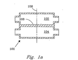
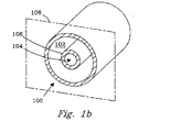
好ましい実施態様の説明
二つのチャンバー102および104の間に壁106を有する熱的化学反応用の容器100を図示する図1aと1bを参照して説明する。これら二つのチャンバー102と104のどちらが反応チャンバーであってもよい。この反応チャンバー102内での反応物のバルク・フロー(bulk flow) は、横断面108に対し実質的に垂直である。この容器100は、図1aに示したような積層チャンバーでも、図1bに示したようなネスト構造のチャンバーでもよい。この反応チャンバー中での反応は、吸熱反応でも発熱反応でもよい。DESCRIPTION OF THE PREFERRED EMBODIMENTS A thermal
熱的化学反応では、定常状態での生成速度(速度論的反応速度)は、その反応部位への(吸熱反応)または反応部位からの(発熱反応)熱伝達の速度により制約される。発熱反応の場合には、熱の除去速度が小さいと望ましくない副反応を促進することがあり、または、その反応器内での熱的ホットスポットの発生または熱的暴走の原因になる。工業的な発熱反応器は、ホットスポットおよび熱的暴走を避けるために、ワンパス当たり(per pass)低い転化率で操業されることが多い。熱除去性が向上すると、単位反応器設備の容積当たりの生産速度をより大きくして安全に操業することが可能であろう。向上した熱伝達速度と、それにより向上した生産速度を得るために、この反応チャンバーは、反応チャンバー容積中に多孔性の挿入体(示されていない)を含んでいるのが望ましく、その場合、反応チャンバー容積中の多孔性の挿入体の平均多孔度は 1より小さく、触媒部位までの反応物(一種または複数)の輸送距離は 3mmより大きくなく、そして高さ(熱源から熱溜めまでの熱的伝達距離)は 2インチより大きくなく、それによりその多孔性の挿入体を通して、向上した熱伝達速度で反応熱が伝達される。 In a thermal chemical reaction, the steady state production rate (kinetic reaction rate) is constrained by the rate of heat transfer to or from the reaction site (endothermic reaction) (exothermic reaction). In the case of an exothermic reaction, a low heat removal rate may promote undesirable side reactions, or cause thermal hot spots or thermal runaway in the reactor. Industrial exothermic reactors are often operated at low conversion per pass to avoid hot spots and thermal runaway. If the heat removal performance is improved, it will be possible to operate safely by increasing the production rate per unit capacity of the reactor unit. In order to obtain an improved heat transfer rate and thereby an improved production rate, the reaction chamber preferably includes a porous insert (not shown) in the reaction chamber volume, in which case The average porosity of the porous insert in the reaction chamber volume is less than 1, the transport distance of the reactant (s) to the catalytic site is not greater than 3 mm, and the height (heat from the heat source to the heat sink) Transfer distance) is not greater than 2 inches, so that reaction heat is transferred through the porous insert at an improved heat transfer rate.
この多孔性の挿入体は、粉末、多孔性モノリス(金属またはセラミック発泡体、フェルト、ハニカム構造体、チューブバンク(tube bank)、積層マイクロチャネル集合体およびそれらの組合せ、を含むがそれらに限定はされない)、繊維、ワッド(wad)(例えば、スチール・ウール)または、それらの組合せであってもよい。触媒反応器用の、使用済み触媒の取換えコストの観点から、この多孔性挿入体は、その反応チャンバーから除去できることが望ましい。この多孔性挿入体は、その反応チャンバー容積を通しての反応物のために単一またはマルチ・フロー通路を提供するように配置されてもよい。 This porous insert includes, but is not limited to, powders, porous monoliths (metal or ceramic foams, felts, honeycomb structures, tube banks, laminated microchannel assemblies and combinations thereof). Not), fibers, wad (eg, steel wool), or combinations thereof. In view of the replacement cost of the spent catalyst for the catalytic reactor, it is desirable that the porous insert can be removed from the reaction chamber. The porous insert may be arranged to provide a single or multi-flow passage for reactants through the reaction chamber volume.
望ましくは、この反応チャンバーの容積は、バルク反応物の流れに平行に、6 インチまたはそれ以下の長さを有し、そして高さ:熱溜めから熱源までの熱的距離、は 2インチまたはそれ以下の高さを有する。このように限定された長さと高さは、より速い熱伝達を可能にする短い距離を提供する。さらに、この短い長さが、その反応チャンバーを通しての総圧力低下を低減する。 Desirably, the volume of the reaction chamber has a length of 6 inches or less, parallel to the bulk reactant flow, and height: the thermal distance from the heat sink to the heat source, 2 inches or less. It has the following height. This limited length and height provides a short distance that allows for faster heat transfer. In addition, this short length reduces the total pressure drop through the reaction chamber.
この熱伝達チャンバー(熱交換器)は、反応チャンバーの容積と熱的に接触しており、この熱伝達チャンバーは、その熱伝達チャンバーと反応チャンバーの間の壁106を横断して、その向上した熱伝達速度で熱を伝達し、それにより、この熱的化学反応用の反応チャンバーの容積当たりで向上した生産速度が得られることになる。 The heat transfer chamber (heat exchanger) is in thermal contact with the volume of the reaction chamber, and the heat transfer chamber is enhanced across the
熱的触媒化学反応の場合、望ましい触媒は、多孔性支持体、その上に溶液沈着された界面層および、その界面層上の触媒物質を有する。より望ましい触媒は、多孔性支持体、緩衝層、界面層および触媒物質を有する。どの層も、連続層でもよく、または、スポットあるいはドットの形状または間隙や孔を有する層の形状をした非連続層でもよい。 In the case of thermal catalytic chemistry, the desired catalyst has a porous support, an interfacial layer deposited thereon and a catalytic material on the interfacial layer. More desirable catalysts have a porous support, a buffer layer, an interface layer and a catalytic material. Any layer may be a continuous layer, or it may be a discontinuous layer in the form of a spot or dot or a layer with gaps or holes.
この多孔性支持体は、多孔性セラミックまたは金属発泡体でもよい。本発明で使用するのに適した他の多孔性支持体に含まれるのは、炭化物、窒化物および複合材料である。層を沈着させる前で、この多孔性支持体は、水銀ポロシメトリーで測定した多孔度が少なくとも 5%で、そして光学および走査型電子顕微鏡で測定した平均孔径(孔径の和/孔の数)は、1 μm〜1000μmである。この多孔性支持体は、約30%〜約99%の多孔度、より望ましくは約60%〜約98%の多孔度を有するのが望ましい。多孔性支持体の望ましい形状は、発泡体、フェルト、ワッドおよびそれらの組合せである。発泡体は、その構造体を通り抜ける孔を規定する連続壁を有する構造体である。フェルトは、繊維間に間隙空間を有する繊維の構造体である。ワッドは、スチール・ウールのような絡み合ったストランドの構造体である。あまり望ましくはないが、多孔性支持体は、ペレットおよびハニカムのような他の多孔性媒体を含んでいてもよいが、それらは上述の多孔度および孔径特性を有することを前提とする。金属発泡体のオープンセルは、インチ当たり約20個(ppi:pores per inch)から約3000ppi そしてより望ましくは約20〜約1000ppi さらにより望ましくは約40〜約120ppiである。ppi は、インチ当たりの孔の最大数として定義される(等方性の材料では、測定の方向は重要でないが、異方性の材料では、孔の数が最大になる方向で測定される)。本発明では、ppi は走査型電子顕微鏡で測定される。本発明での多孔性支持体は、小さい圧力低下、常用のセラミック・ペレット支持体より改善された熱伝導性、および化学反応器中への装填/取出しの容易さを含む幾つかの利点を提供することが見いだされた。 The porous support may be a porous ceramic or a metal foam. Other porous supports suitable for use in the present invention include carbides, nitrides and composite materials. Prior to layer deposition, the porous support had a porosity of at least 5% as measured by mercury porosimetry and the average pore size (sum of pore sizes / number of pores) measured by optical and scanning electron microscopy was 1 μm to 1000 μm. The porous support desirably has a porosity of about 30% to about 99%, more desirably about 60% to about 98%. Desirable shapes for the porous support are foam, felt, wad and combinations thereof. A foam is a structure having a continuous wall that defines pores through the structure. A felt is a fiber structure having interstitial spaces between fibers. A wad is an intertwined strand structure such as steel wool. Although less desirable, the porous support may include other porous media such as pellets and honeycombs, provided that they have the porosity and pore size characteristics described above. The open cell of the metal foam is from about 20 pores per inch (ppi) to about 3000 ppi and more preferably from about 20 to about 1000 ppi and even more preferably from about 40 to about 120 ppi. ppi is defined as the maximum number of holes per inch (for isotropic materials, the direction of measurement is not important, but for anisotropic materials, it is measured in the direction that maximizes the number of holes) . In the present invention, ppi is measured with a scanning electron microscope. The porous support in the present invention offers several advantages, including a small pressure drop, improved thermal conductivity over conventional ceramic pellet supports, and ease of loading / unloading into chemical reactors. I found something to do.
緩衝層(もし存在するなら)は、支持体層および界面層の両方と異なる組成および/または密度を有し、そして望ましくは多孔性支持体層と界面層の熱膨張係数の中間の熱膨張係数を有する。この緩衝層は金属酸化物また金属炭化物であるのが望ましい。本出願者達は、この緩衝層は、蒸着した層が、数回の熱的サイクルの後でも、より良好な接着と剥離抵抗性を示すという理由で優れていることを見いだした。より望ましくは、この緩衝層はAl2O3 、TiO2 、SiO2 およびZrC2 またはそれらの組合せである。さらに特定すれば、このAl2O3 はα‐Al2O3 、γ‐Al2O3 およびそれらの組合せである。その酸素拡散に対する素晴らしい抵抗性のために、α‐Al2O3 がより望ましい。それ故、高温酸化に対する抵抗性は、その多孔性支持体の上にコートされたアルミナにより改善され得ることが予想される。緩衝層は二層またはそれ以上の組成の異なるサブ層から形成されていてもよい。この多孔性支持体が金属、例えばステンレス鋼発泡体の場合、推奨される態様では、二つの組成的に異なる二つのサブ層(示されていない)から形成されている緩衝層を有している。第1サブ層(多孔性支持体に接している)は、その多孔性支持体に対し良好な接着性を示すという理由で、TiO2 であるのが望ましい。第2サブ層は、そのTiO2 の上に乗せられるα‐Al2O3 が望ましい。推奨される一つの態様で、このα‐Al2O3 は、緻密な層であり、下に横たわる金属表面の素晴らしい保護を果たす。次いで、アルミナのような、あまり緻密でない大きい表面積の界面層が、触媒活性層用の支持体として沈着される場合もある。The buffer layer (if present) has a different composition and / or density than both the support layer and the interfacial layer, and preferably has a thermal expansion coefficient intermediate that of the porous support layer and the interfacial layer. Have This buffer layer is preferably a metal oxide or metal carbide. Applicants have found that this buffer layer is superior because the deposited layer exhibits better adhesion and peel resistance even after several thermal cycles. More preferably, the buffer layer is Al 2 O 3 , TiO 2 , SiO 2 and ZrC 2 or combinations thereof. More specifically, the Al 2 O 3 is α-Al 2 O 3 , γ-Al 2 O 3 and combinations thereof. Α-Al 2 O 3 is more desirable because of its excellent resistance to oxygen diffusion. Therefore, it is expected that the resistance to high temperature oxidation can be improved by alumina coated on the porous support. The buffer layer may be formed of two or more sublayers having different compositions. If the porous support is a metal, such as a stainless steel foam, the recommended embodiment has a buffer layer formed from two compositionally different two sub-layers (not shown). . The first sublayer (which is in contact with the porous support) is preferably TiO 2 because it exhibits good adhesion to the porous support. The second sublayer is preferably α-Al 2 O 3 placed on the TiO 2 . In one recommended embodiment, the α-Al 2 O 3 is a dense layer that provides excellent protection of the underlying metal surface. A less dense, high surface area interfacial layer such as alumina may then be deposited as a support for the catalytically active layer.
普通、この多孔性支持体は、界面層の熱膨張係数と異なる熱膨張係数を有する。従って、高温触媒(T>150 ℃)の場合、この二つの熱膨張係数の間での転移のために緩衝層が必要である。この緩衝層の熱膨張係数は、多孔性支持体および界面層の熱膨張係数に適合した熱膨張係数を得るために、注文に応じて、組成を制御することによって調整されることができる。この緩衝層のもう一つの利点は、それが、裸の金属発泡体表面により誘き起こされるコークス化やクラッキングのような副反応に対する抵抗性を提供することである。触媒燃焼のような大きい表面積の支持体を必要としない化学反応では、この緩衝層は、強い金属‐金属酸化物間相互作用によりその触媒金属を安定化する。大きい表面積の支持体を必要とする化学反応では、この緩衝層は、その大きい表面積の界面層に対するより強い結合を提供する。この緩衝層は、開口およびピンホールを含んでいないのが望ましく、これは、下に横たわる支持体に素晴らしい保護を提供する。この緩衝層は、ポーラスでないことがより望ましい。この緩衝層は、多孔性支持体の平均孔径の1/2 より小さい厚さを有している。望ましくは、この緩衝層の厚さは約0.05と約10μmの間であり、 5μmより薄いのがより望ましい。この緩衝層は、高い温度で熱的および化学的安定性を発揮すべきである。 Usually, this porous support has a coefficient of thermal expansion different from that of the interface layer. Thus, for high temperature catalysts (T> 150 ° C.), a buffer layer is required for the transition between these two coefficients of thermal expansion. The thermal expansion coefficient of this buffer layer can be adjusted by controlling the composition according to the order in order to obtain a thermal expansion coefficient compatible with the thermal expansion coefficient of the porous support and the interface layer. Another advantage of this buffer layer is that it provides resistance to side reactions such as coking and cracking evoked by the bare metal foam surface. In chemical reactions that do not require a large surface area support, such as catalytic combustion, the buffer layer stabilizes the catalytic metal by strong metal-metal oxide interactions. In chemical reactions that require a large surface area support, the buffer layer provides a stronger bond to the high surface area interface layer. The buffer layer preferably does not include openings and pinholes, which provide great protection for the underlying support. More preferably, the buffer layer is not porous. This buffer layer has a thickness smaller than 1/2 of the average pore diameter of the porous support. Desirably, the thickness of this buffer layer is between about 0.05 and about 10 μm, more preferably less than 5 μm. This buffer layer should exhibit thermal and chemical stability at high temperatures.
本発明の幾つかの態様では、緩衝層なしで、十分な接着性と化学的安定性が得られ、従って、緩衝層を省略することが可能で、かくて、コストを節約でき、追加的容積を与え、更に、触媒からの熱伝達を向上させる。 In some embodiments of the present invention, sufficient adhesion and chemical stability can be obtained without a buffer layer, and therefore the buffer layer can be omitted, thus saving cost and adding additional volume. And further improves heat transfer from the catalyst.
この界面層は、窒化物、炭化物、硫化物、ハロゲン化物、金属酸化物、炭素およびそれらの組合せから構成されることができる。この界面層は、大きい表面積を提供し、及び/または担持触媒用に望ましい触媒‐支持体相互作用を提供する。この界面層は、触媒支持体として普通用いられている任意の物質を含んでいてもよい。望ましくは、この界面層は金属酸化物である。金属酸化物の例に含まれるのは、γ‐Al2O3 、SiO2 、ZrO2 、TiO2 、酸化タングステン、酸化マグネシウム、酸化バナジウム、酸化クロム、酸化マンガン、酸化鉄、酸化ニッケル、酸化コバルト、酸化銅、酸化亜鉛、酸化モリブデン、酸化スズ、酸化カルシウム、酸化アルミニウム、ランタン系列酸化物(一種または複数)、ゼオライト(一種または複数)、およびそれらの組合せであるが、これらに限定はされない。この界面層は、その上に、さらに何等かの触媒活性のある物質を沈着することなしに触媒活性層として寄与してもよい。しかし普通、この界面層は、触媒活性層と組合せて用いられる。この界面層は、二種またはそれ以上の組成の異なるサブ層から形成されてもよい。この界面層は、多孔性支持体の平均孔径の1/2 より薄い厚さを有している。望ましくは、この界面層は、約 0.5と約 100μmの範囲の厚さ、より望ましくは約 1〜約50μmの厚さである。この界面層は、結晶性でも非晶性でもよく、そして望ましくは、少なくとも1 m2 /gのBET 表面積を有している。This interfacial layer can be composed of nitrides, carbides, sulfides, halides, metal oxides, carbon and combinations thereof. This interfacial layer provides a large surface area and / or provides the desired catalyst-support interaction for supported catalysts. This interfacial layer may comprise any material commonly used as a catalyst support. Desirably, the interface layer is a metal oxide. Examples of metal oxides include γ-Al 2 O 3 , SiO 2 , ZrO 2 , TiO 2 , tungsten oxide, magnesium oxide, vanadium oxide, chromium oxide, manganese oxide, iron oxide, nickel oxide, cobalt oxide. , Copper oxide, zinc oxide, molybdenum oxide, tin oxide, calcium oxide, aluminum oxide, lanthanum series oxide (s), zeolite (s), and combinations thereof, but are not limited thereto. This interfacial layer may also serve as a catalytically active layer without depositing any further catalytically active material thereon. Usually, however, this interfacial layer is used in combination with a catalytically active layer. This interface layer may be formed from two or more sub-layers having different compositions. This interfacial layer has a thickness that is less than ½ of the average pore size of the porous support. Desirably, the interfacial layer has a thickness in the range of about 0.5 and about 100 μm, more desirably about 1 to about 50 μm. This interfacial layer may be crystalline or amorphous and desirably has a BET surface area of at least 1 m 2 / g.
触媒活性な物質(存在する場合には)は、界面層の上に沈着されることができる。或いはまた、触媒活性な物質は、その界面層と共に同時に沈着されることができる。この触媒活性層(存在する場合には)は、典型的には、界面層の上に直接に沈着される。この触媒活性層が界面層上に“配置”(“disposed on”)または“沈着”(“deposited on”)されるということには、支持体層(即ち、界面層)表面上に、その支持体層中の割れ目中に、およびその支持体層中の開放孔中に、ミクロな触媒活性粒子が分散されるという通常の理解が含まれている。この触媒活性層は、非限定的に、貴金属、遷移金属およびそれらの組合せを含む触媒金属;非限定的に、アルカリ元素、アルカリ土類元素、ホウ素、ガリウム、ゲルマニウム、ヒ素、セレン、テルル、タリウム、鉛、ビスマス、ポロニウム、マグネシウム、チタン、バナジウム、クロム、マンガン、鉄、ニッケル、コバルト、銅、亜鉛、ジルコニウム、モリブデン、スズ、カルシウム、アルミニウム、ケイ素、ランタン系列元素(一種または複数)、およびそれらの組合せを含む金属の酸化物;複合材料;ゼオライト(一種または複数);窒化物;炭化物;硫化物;ハロゲン化物;ホスフェート;および上述の任意の物の組合せを含んでもよい。 Catalytically active material (if present) can be deposited on the interfacial layer. Alternatively, the catalytically active material can be deposited simultaneously with its interfacial layer. This catalytically active layer (if present) is typically deposited directly on the interfacial layer. When this catalytically active layer is “disposed on” or “deposited on” on the interfacial layer, it means that its support on the surface of the support layer (ie, interfacial layer) The usual understanding is included that microcatalytically active particles are dispersed in cracks in the body layer and in open pores in the support layer. The catalytically active layer may be a catalytic metal including, but not limited to, noble metals, transition metals and combinations thereof; , Lead, bismuth, polonium, magnesium, titanium, vanadium, chromium, manganese, iron, nickel, cobalt, copper, zinc, zirconium, molybdenum, tin, calcium, aluminum, silicon, lanthanum series element (s), and those Metal oxides comprising a combination of: composites; zeolite (s); nitrides; carbides; sulfides; halides: phosphates; and combinations of any of the foregoing.
この触媒構造物の物質伝達阻害を緩和するために、触媒含浸法は、50μm未満、望ましくは20μm未満の深さを有する多孔性界面層を形成するのが望ましい。従って、この拡散経路長は標準の触媒粒子の場合より少なくとも5ファクター短い。このより薄い含浸触媒構造は、より短い熱伝達経路に因り、熱伝達性も高める。 In order to mitigate the mass transfer inhibition of the catalyst structure, it is desirable that the catalyst impregnation method forms a porous interface layer having a depth of less than 50 μm, preferably less than 20 μm. Therefore, this diffusion path length is at least 5 factors shorter than that of standard catalyst particles. This thinner impregnated catalyst structure also increases heat transfer due to the shorter heat transfer path.
この触媒構造物は、任意の幾何学的構造をしていてもよい。望ましくは、この触媒は、発泡体、フェルト、ワッドおよびそれらの組合せのような多孔性構造である。この触媒(その支持体と触媒材料を含めて)は、反応チャンバー内に適合する大きさであるのが望ましい。この触媒は、多孔性の繋がった物質の単一ピースであってもよく、または物理的に接触している多数のピースであってもよい。この触媒は、繋がった物質で、その触媒を通して分子が拡散できるように繋がった多くの孔を有しているのが望ましい。この望ましい態様では、その触媒は、気体がその触媒の回りを通るより、その触媒(単一または多くのピース)を実質的に通り抜けて流れるように反応チャンバー中に設置され得る。一つの推奨される態様では、その触媒の横断面積は、その反応チャンバーの横断面積の少なくとも80%、より望ましくは、少なくとも95%を占める。推奨される態様で、その触媒として活性な金属は、その触媒を通り抜ける反応物が、その触媒を通り抜ける通路に沿った如何なる場所でも反応し得るように、触媒全体の表面に分布しており;これが、使用されない大きい体積を有するペレットタイプの触媒または、そのペレットタイプ内部で使用されていない大容積の空間または、触媒として非効率に使用されている空間を有する触媒より優れている有意な利点である。また、充填された粉末は深刻な圧力低下の原因になるので、この多孔性の触媒は、粉末の触媒よりも優れている。この触媒は、BET の方法で測定した約0.5 m2/gより大きい、より望ましくは約2.0 m2/gより大きい表面積を有するのが望ましい。The catalyst structure may have any geometric structure. Desirably, the catalyst is a porous structure such as foam, felt, wad and combinations thereof. The catalyst (including its support and catalyst material) is preferably sized to fit within the reaction chamber. The catalyst may be a single piece of porous tethered material, or it may be a number of pieces in physical contact. The catalyst is preferably a connected substance and has many pores connected so that molecules can diffuse through the catalyst. In this preferred embodiment, the catalyst can be placed in the reaction chamber such that gas flows substantially through the catalyst (single or many pieces) rather than through the catalyst. In one recommended embodiment, the cross-sectional area of the catalyst occupies at least 80%, more desirably at least 95% of the cross-sectional area of the reaction chamber. In a recommended manner, the catalytically active metal is distributed across the surface of the entire catalyst so that reactants passing through the catalyst can react anywhere along the passage through the catalyst; This is a significant advantage over a catalyst of a pellet type having a large volume that is not used, or a large volume of space that is not used inside the pellet type or a space that is used inefficiently as a catalyst. Also, the porous catalyst is superior to the powder catalyst because the filled powder causes a serious pressure drop. The catalyst preferably has a surface area measured by the BET method of greater than about 0.5 m 2 / g, more desirably greater than about 2.0 m 2 / g.
本発明の触媒は、それらが発揮する諸性質によっても特性化できる。これらの諸性質を有効に働らかせるために制御できる因子に含まれるのは、多孔性支持体、緩衝層、界面層および触媒活性層の選択:熱膨張係数の勾配付け(grdation)、結晶度、金属‐支持体相互作用、触媒の大きさ、支持体の熱伝導率、多孔度、反応チャンバーからの熱伝導、沈着技術および本明細書の説明の見解から明らかである他の因子、である。本発明の触媒の特定の推奨される態様は、一種またはそれ以上の次の諸性質を発揮する:空気中熱サイクル三回後の接着性、即ち、この触媒は、SEM(走査型電子顕微鏡)解析により薄片化が 2% (面積で)より小さいことを示す;酸化抵抗性、反応物(一種または複数)の転化率、接触/滞留時間、製品選択性、圧力低下および生産速度;である。 The catalysts of the present invention can also be characterized by the properties they exhibit. Factors that can be controlled to make these properties work effectively include selection of porous support, buffer layer, interface layer and catalytically active layer: thermal expansion coefficient gradient, crystallinity , Metal-support interaction, catalyst size, support thermal conductivity, porosity, heat transfer from reaction chamber, deposition technique and other factors that are evident from the view of the description herein . Certain recommended embodiments of the catalyst of the present invention exhibit one or more of the following properties: Adhesion after three thermal cycles in air, i.e. the catalyst is SEM (scanning electron microscope) Analysis shows that flaking is less than 2% (in area); oxidation resistance, conversion of reactant (s), contact / residence time, product selectivity, pressure drop and production rate.
本発明の触媒を製造するために推奨される方法は、多孔性支持体を選ぶ工程、その多孔性支持体上に緩衝層を沈着させる工程および、その上に界面層を沈着させる工程を有する。場合により、触媒層は、界面層に沈着させてもよく、またはこの界面層と触媒層の両方を、その緩衝層の上に同時に沈着させてもよい。 The recommended method for producing the catalyst of the present invention comprises the steps of selecting a porous support, depositing a buffer layer on the porous support, and depositing an interfacial layer thereon. Optionally, the catalyst layer may be deposited on the interface layer, or both the interface layer and the catalyst layer may be deposited simultaneously on the buffer layer.
金属は、非ポーラスで平滑なウエブ表面を有しているから、緩衝層の沈着が阻害される可能性がある。この問題を緩和する一つの方法は、化学的エッチングによりその金属の表面を粗くすることである。表面積の大きいγ‐アルミナに担持された金属触媒の金属発泡体への接着は、鉱酸溶液:例えば 0.1〜1M-HClを用いる化学的エッチングによりその金属発泡体の表面を粗くすることにより有意に改善される。粗面化したウエブ表面は、熱サイクル時の触媒層の剥離に対しても改善された抵抗性を示す。金属発泡体が多孔性支持体として用いられる推奨される一つの態様では、その金属発泡体は、緩衝層を蒸着する前にエッチングされる。エッチングには、酸、例えば HClを用いるのが望ましい。 Since the metal has a non-porous and smooth web surface, the deposition of the buffer layer may be inhibited. One way to alleviate this problem is to roughen the surface of the metal by chemical etching. The adhesion of the metal catalyst supported on the large surface area γ-alumina to the metal foam is significantly increased by roughening the surface of the metal foam by chemical etching using a mineral acid solution: for example, 0.1-1M HCl. Improved. The roughened web surface exhibits improved resistance to catalyst layer flaking during thermal cycling. In one recommended embodiment where a metal foam is used as the porous support, the metal foam is etched prior to depositing the buffer layer. It is desirable to use an acid such as HCl for the etching.
緩衝層の沈着は、化学蒸着、物理的蒸着および、それらの組合せ(これらに限定はされない)を含む蒸着によるのが望ましい。驚くべきことに、普通、高温で行われる蒸着が、その多孔性支持体の表面への緩衝層の良好な接着を提供する多結晶性または非晶性の相を生じることが見いだされた。この方法は、金属多孔性支持体に金属酸化物緩衝層を接着させるために特に便利である。或いはまた、この緩衝層は、溶液コーティング法によっても得られる。例えば、この溶液コーテイング法は、その金属表面を水蒸気に曝して表面ヒドロキシル基を生成させ、金属表面を官能性化する工程を含み、次いで表面反応とアルコキシドの加水分解により金属酸化物のコーティングが得られる。この溶液コーティング法は、緩衝層を沈着させる、より低コストの方法として推奨される。 The buffer layer deposition is preferably by vapor deposition including, but not limited to, chemical vapor deposition, physical vapor deposition, and combinations thereof. Surprisingly, it has been found that vapor deposition, usually performed at high temperatures, yields a polycrystalline or amorphous phase that provides good adhesion of the buffer layer to the surface of the porous support. This method is particularly convenient for adhering a metal oxide buffer layer to a metal porous support. Alternatively, this buffer layer can also be obtained by a solution coating method. For example, this solution coating method includes the steps of exposing the metal surface to water vapor to generate surface hydroxyl groups and functionalizing the metal surface, followed by surface reaction and alkoxide hydrolysis to obtain a metal oxide coating. It is done. This solution coating method is recommended as a lower cost method of depositing a buffer layer.
界面層は、これら技術用に知られている前駆体を使用する蒸着または溶液沈着により形成されるのが望ましい。適した前駆体に含まれるのは、有機金属化合物、ハロゲン化物、カルボニル類、アセトネート類、アセテート類、金属、金属酸化物のコロイド状分散物、硝酸塩、スラリー類などである。例えば、多孔性アルミナ界面層は、PQアルミナ(Nyacol Products,Ashland,MA) コロイド状分散物で洗浄‐コートされ、次いで、真空オーブン中で一晩乾燥され、そして 500℃で 2時間か焼される。 The interfacial layer is preferably formed by vapor deposition or solution deposition using precursors known for these techniques. Included among suitable precursors are organometallic compounds, halides, carbonyls, acetonates, acetates, metals, colloidal dispersions of metal oxides, nitrates, slurries, and the like. For example, a porous alumina interfacial layer is washed-coated with a PQ alumina (Nyacol Products, Ashland, Mass.) Colloidal dispersion, then dried in a vacuum oven overnight and calcined at 500 ° C. for 2 hours .
触媒活性物質は、任意の適切な方法で沈着される。例えば、触媒前駆体が、コロイド状金属粒子上に沈着され、そして、緩衝液をコートした多孔性支持体の上にスラリー・コーテイングされ、次いで乾燥され、そして還元される。 The catalytically active material is deposited by any suitable method. For example, the catalyst precursor is deposited on colloidal metal particles and slurry coated on a porous substrate coated with a buffer, then dried and reduced.
本発明の特定の態様は、滞留時間または接触時間という用語により特性化できる。これらの用語は、この技術分野で十分よく規定された意味を有する。接触時間とは、触媒チャンバーの総容積を、入口反応物の総流速(F-Total と定義される)で割った値であり、この場合反応物は、標準状態に較正された理想気体であると仮定される[即ち、触媒チャンバーの容積/STPにおけるF-Total(ここでSTP は 273K,1atm)]。触媒チャンバーの容積とは、触媒ゾーンの直近および取囲んでいる体積を含む。一例として、そのチャネルの1/4 を粉末で充填すると、その触媒チャンバーの容積とは、ガスが流れることができ、そして、それが触媒と接触し得る領域だけを含むことになる;即ち、総チャネルの1/4 だけが、この計算に含まれることになる。デッド・スペースの容積、即ち、入口の上部の隙間(header)、下部の隙間(footer)などは、この計算では考慮さない。滞留時間(平均滞留時間を意味する)は、触媒チャンバーの総容積を、その反応器中でのその反応物の実際の温度と圧力に較正された入口反応物の総流速で割った値(即ち、触媒チャンバーの容積/実際の条件に較正したF-Total)である。STP におけるF-Totalは、反応物(全ての反応物および、存在するなら稀釈剤)の総体積流速である。入ってくるガスは、普通、標準条件にセットされた質量流量制御装置で測量される。即ち、利用者は、希望のSTP 流速をプリセットする。実際の条件に較正したF-Total は F-Total-STP×(Kで示した絶対温度)/273×1 気圧/(atm で示した実際のP)である:この値が、滞留時間または反応器内部での“実時間”を計算するために用いられる。大半の実務者は、接触時間を使用する方を好むが、これは、反応温度などを10℃段階で高くしながら、時間変数を固定して維持するのが便利な方法だからである。 Certain embodiments of the invention can be characterized by the terms residence time or contact time. These terms have a well-defined meaning in the art. Contact time is the total volume of the catalyst chamber divided by the total flow rate of the inlet reactant (defined as F-Total), where the reactant is an ideal gas calibrated to standard conditions. [Ie, F-Total in catalyst chamber volume / STP (where STP is 273 K, 1 atm)]. The volume of the catalyst chamber includes the volume immediately adjacent to and surrounding the catalyst zone. As an example, when 1/4 of the channel is filled with powder, the volume of the catalyst chamber will include only the area where gas can flow and where it can contact the catalyst; Only 1/4 of the channel will be included in this calculation. The dead space volume, i.e., the upper header, lower footer, etc., is not considered in this calculation. Residence time (meaning average residence time) is the total volume of the catalyst chamber divided by the total inlet reactant flow rate calibrated to the actual temperature and pressure of the reactant in the reactor (ie, F-Total) calibrated to the volume of the catalyst chamber / actual conditions. F-Total in STP is the total volume flow rate of the reactants (all reactants and diluent if present). Incoming gas is usually measured with a mass flow controller set to standard conditions. That is, the user presets the desired STP flow rate. F-Total calibrated to actual conditions is F-Total-STP x (absolute temperature in K) / 273 x 1 atmosphere / (actual P in atm): this value is the residence time or reaction Used to calculate “real time” inside the instrument. Most practitioners prefer to use contact time, because it is a convenient way to keep the time variable fixed while raising the reaction temperature etc. in the 10 ° C step.
本発明はさらに、本発明の触媒を含む反応チャンバーに少なくとも一つの反応物を通す工程、該少なくとも一つの反応物を少なくとも一つの生成物に転化させる工程、そしてその生成物をその反応チャンバーの外に通過させる工程、を含む触媒接触法を提供する。推奨される態様では、この触媒接触法は、マイクロチャネルを有する装置中で行われる。マイクロチャネルは、少なくとも一方の寸法が約1mm またはそれ以下である。適したマイクロチャネル装置および様々な工程関連ファクターの実例が、米国特許第5,611,214、5,811,062、5,534,328号明細書、および米国特許出願第08/883,643、08/938,228、09/375,610、09/123,781号、同時出願されている、米国特許出願第09/492,950(代理人ドケット番号E-1666A-CIP)、09/375,614(1999年 8月17日出願)および09/265,227(1999年 3月 8日出願)に説明されており、これら全ては、十分に再現できるように、以下に引用参照されている。もう一つの推奨される態様では、この触媒は、反応チャンバーへの挿入と取出しが容易なモノリス:単一の繋がっているが多孔性の触媒ピース;または、一緒に積重ねられている数個の繋がっているピース(充填された粉末の層またはペレットまたはマイクロチャネルの壁上のコ一ティング、ではない)である。このピースまたは複数の触媒ピースのスタックは、幅が 0.1mm〜約 2cmであるのが望ましく、厚さが、望ましくは1cm 未満、より望ましくは、約 1〜約 3mmである。本発明の触媒は、化学的安定性、繰返し熱サイクリングに対する安定性、触媒の効率的な装填と取出し、大きい熱伝達および質量伝達速度、および望ましい触媒活性の維持などの多くの利点を、触媒接触工程に提供する。 The invention further includes passing at least one reactant through a reaction chamber containing the catalyst of the invention, converting the at least one reactant to at least one product, and removing the product from the reaction chamber. And a step of passing the catalyst through the catalyst. In a recommended embodiment, the catalytic contact method is performed in an apparatus having microchannels. The microchannel has at least one dimension of about 1 mm or less. Examples of suitable microchannel devices and various process-related factors are described in US Pat. Nos. 5,611,214, 5,811,062, 5,534,328, and US patent application Ser. No. 08 / 883,643, 08 / 938,228, 09 / 375,610, 09 / 123,781, U.S. patent application 09 / 492,950 (attorney docket number E-1666A-CIP), 09/375, filed concurrently. 614 (filed Aug. 17, 1999) and 09 / 265,227 (filed Mar. 8, 1999), all of which are referenced below for full reproduction. In another preferred embodiment, the catalyst is a monolith that is easy to insert and remove from the reaction chamber: a single tethered but porous catalyst piece; or several tethers stacked together. Piece (not a layer of filled powder or pellets or coating on the walls of the microchannel). The piece or stack of catalyst pieces desirably has a width of 0.1 mm to about 2 cm and a thickness of desirably less than 1 cm, more desirably from about 1 to about 3 mm. The catalyst of the present invention offers many advantages such as chemical stability, stability against repeated thermal cycling, efficient loading and unloading of the catalyst, high heat and mass transfer rates, and maintenance of the desired catalytic activity. Provide to the process.
望ましい態様の熱交換器の組立てには、高い熱効率と短い接触時間を得るために、薄いシートまたはチューブが用いられる。反応チャネルと熱交換チャネルの間のウエブの厚さは、変えることができるが、約0.01インチと約0.25インチの間であるのが望ましい。熱交換チャネルに推奨される厚さ(熱伝達チャネルの最小寸法の厚さを意味する)は、100 ミクロン〜10ミリメートルの範囲であるのが望ましい。いくつかの推奨される態様では、この最小寸法は、チャネル幅である場合もあり、他の態様では、チャネル高さである場合もある。その望ましい厚さは250ミクロン〜3 ミリメートルである。熱伝達流体の流れは、反応物の流れの方向に対して、向流(counter-current) 、横流(cross-current) または並流(co-current)のいずれでもよい。望ましい熱伝達流体に含まれるのは、燃焼ストリーム(吸熱反応の場合)、オイル(低温反応)および水蒸気である。 The assembly of the preferred embodiment heat exchanger uses thin sheets or tubes to obtain high thermal efficiency and short contact times. The thickness of the web between the reaction channel and the heat exchange channel can vary, but is preferably between about 0.01 inches and about 0.25 inches. The recommended thickness for the heat exchange channel (meaning the thickness of the minimum dimension of the heat transfer channel) is preferably in the range of 100 microns to 10 millimeters. In some recommended aspects, this minimum dimension may be the channel width, and in other aspects it may be the channel height. Its desired thickness is between 250 microns and 3 millimeters. The flow of the heat transfer fluid may be counter-current, cross-current, or co-current with respect to the direction of reactant flow. Desirable heat transfer fluids include combustion streams (in the case of endothermic reactions), oils (low temperature reactions) and water vapor.
マイクロチャネル装置内の金属表面は、緩衝層および界面層のいずれか、または両者でコートされてもよい。これは、本明細書で説明された方法のいずれか、望ましくは蒸着法を用いて行われる。望ましいコーティング材料は、チタニヤおよび5-10%SiO2/Al2O3 を含む。反応チャンバーの内表面、熱交換器およびマイクロチャネル装置の他の表面がコーティングされる場合もある。いくつかの態様では、反応チャンバーの壁は、場合により緩衝層、界面層および触媒活性材料でコーティングされてもよく、標準的にはその触媒活性材料と界面層が一緒になって担持触媒を形成している。コーティングはまた、マイクロチャネル装置へ(又は内へ)の連結管を形成しているチューブおよびパイプの金属壁またはマイクロチャネル装置内部に適用されることもある。The metal surface in the microchannel device may be coated with either the buffer layer, the interface layer, or both. This is done using any of the methods described herein, preferably a vapor deposition method. Desirable coating materials include titania and 5-10% SiO 2 / Al 2 O 3 . The inner surface of the reaction chamber, heat exchangers and other surfaces of the microchannel device may be coated. In some embodiments, the walls of the reaction chamber may optionally be coated with a buffer layer, an interfacial layer, and a catalytically active material, typically the catalytically active material and the interfacial layer together form a supported catalyst. doing. The coating may also be applied to the metal walls of tubes and pipes that form a connecting tube to (or into) the microchannel device or inside the microchannel device.
本発明の方法は、触媒の厚さが約 2cmまたはそれ以下で、そして反応チャンバー壁に接しているか、または近接(約 1mm以内)している反応チャンバー内で行われるのが望ましく、その反応チャンバー壁は、熱交換器と熱的に接触している。反応チャンバーからの(または、への)熱伝達は、それを通って熱が伝達される少なくとも一つのチャンバー壁の上に、望ましくは、その反応チャンバーの、触媒構造体に向かい合った側の壁の上に、マイクロチャネルを付けることにより、向上されるのが望ましい。この触媒は、大きい圧力低下を避けるために、発泡体の中におけるような、繋がっていて、そして比較的大きい孔を有するの望ましい。望ましくは、この触媒中の大きい孔の孔径は、約10μmと約 300μmの間である。 The process of the present invention is preferably carried out in a reaction chamber having a catalyst thickness of about 2 cm or less and in contact with or close to the reaction chamber wall (within about 1 mm). The wall is in thermal contact with the heat exchanger. The heat transfer from (or to) the reaction chamber is on at least one chamber wall through which heat is transferred, preferably on the side of the reaction chamber facing the catalyst structure. It is desirable to improve by attaching a microchannel on top. The catalyst is preferably connected and has relatively large pores, such as in a foam, to avoid large pressure drops. Desirably, the pore size of the large pores in the catalyst is between about 10 μm and about 300 μm.
本発明の触媒接触法に含まれるのは、アセチル化反応、付加反応、アルキル化反応、脱アルキル化反応、水素化脱アルキル化反応、還元的アルキル化反応、アミノ化反応、芳香族化反応、アリール化反応、自熱改質反応、カルボニル化反応、脱カルボニル化反応、還元的カルボニル化反応、カルボキシル化反応、還元的カルボキシル化反応、還元的カップリング反応、縮合反応、クラッキング反応、ハイドロクラッキング反応、環化反応、環状オリゴマ化反応、脱ハロゲン化反応、二量化反応、エポキシ化反応、エステル化反応、交換反応、フィッシャー-トロプシュ反応、ハロゲン化反応、水素化ハロゲン化反応、ホモログ化反応、水和反応、脱水反応、水素化反応、脱水素反応、水素化カルボキシル化反応、ヒドロホルミル化反応、加水素分解反応、ヒドロ金属化反応、ヒドロシリル化反応、加水分解反応、水素処理反応、水素化脱硫反応/水素化脱窒素反応(HDS/HDN)、異性化反応、メタン化反応、メタノール合成反応、メチル化反応、脱メチル化反応、複分解反応、ニトロ化反応、酸化反応、部分酸化反応、重合反応、還元反応、水蒸気/二酸化炭素改質反応、スルホン化反応、テロメリゼーション、エステル交換反応、三量化反応、水性ガスシフト反応(WGS)、および逆水性ガス・シフト反応(RWGS) である。 The catalyst contact method of the present invention includes acetylation reaction, addition reaction, alkylation reaction, dealkylation reaction, hydrodealkylation reaction, reductive alkylation reaction, amination reaction, aromatization reaction, Arylation reaction, autothermal reforming reaction, carbonylation reaction, decarbonylation reaction, reductive carbonylation reaction, carboxylation reaction, reductive carboxylation reaction, reductive coupling reaction, condensation reaction, cracking reaction, hydrocracking reaction , Cyclization reaction, cyclic oligomerization reaction, dehalogenation reaction, dimerization reaction, epoxidation reaction, esterification reaction, exchange reaction, Fischer-Tropsch reaction, halogenation reaction, hydrohalogenation reaction, homologation reaction, water Summation, dehydration, hydrogenation, dehydrogenation, hydrogenated carboxylation, hydroformylation, hydrogenation Decomposition reaction, hydrometallation reaction, hydrosilylation reaction, hydrolysis reaction, hydrotreating reaction, hydrodesulfurization reaction / hydrodenitrogenation reaction (HDS / HDN), isomerization reaction, methanation reaction, methanol synthesis reaction, methylation Reaction, demethylation reaction, metathesis reaction, nitration reaction, oxidation reaction, partial oxidation reaction, polymerization reaction, reduction reaction, steam / carbon dioxide reforming reaction, sulfonation reaction, telomerization, transesterification reaction, trimerization reaction Water gas shift reaction (WGS) and reverse water gas shift reaction (RWGS).
本発明の一つまたは複数の工程は、数十、数百、数千または数百万の小さい反応チャンバーで、各チャンバーは、内径が約 2インチより小さく、望ましくは約2cm より小さく、より望ましくは約 1mm〜約5mm の範囲であるチャンバーで平行して行なうことができる。この一つまたは複数の工程はまた、シリーズで(直列的に)運転することもできる。例えば、一つの反応チャンバーからの複数の生成物が、同一のまたは異なる一つの触媒を有するもう一つの他の反応チャンバーに供給されることもある。直列の複数の反応器はまた、その同じ反応チャンバーの内部に一連の異なる触媒を入れて運転することもできる。反応生成物は、捕集され、そして、例えば、タンク内に貯蔵してもよく、後続の反応で直接使用することもできる。 One or more steps of the present invention are tens, hundreds, thousands, or millions of small reaction chambers, each chamber having an inner diameter of less than about 2 inches, preferably less than about 2 cm, more preferably Can be performed in parallel in chambers ranging from about 1 mm to about 5 mm. The one or more steps can also be operated in series (in series). For example, multiple products from one reaction chamber may be fed to another reaction chamber having the same or different catalyst. Multiple reactors in series can also be operated with a series of different catalysts within the same reaction chamber. The reaction product can be collected and stored, for example, in a tank or used directly in subsequent reactions.
本発明の反応器と方法は、それらが発揮する様々な性質により特性化され得る。熱流束(heat flux) は、本発明での特に重要な特性である。チャンバー壁の体積を含めての、反応チャンバー(一つまたは複数)と熱交換器(一つまたは複数)の体積の和に対して、本発明は、定常状態での運転中に、少なくとも約 0.6w/ccの、より望ましくは約 1w/ccより上の、さらにより望ましくは約 5〜約250W/cc の範囲の、そしてもう一つの望ましい範囲としては、約10〜約100W/cc の範囲の、熱流束を示すのが望ましい。これらの熱流束は、短い接触時間と、反応チャンバーを通しての小さい圧力低下で得られる。この接触時間は、望ましくは約0.3 秒より短く、より望ましくは約 0.1秒より短く、さらにより望ましくは約0.05秒より短く、そしてなお一層望ましくは約0.01秒より短い。反応チャンバーを通しての圧力低下は、望ましくは約15psig(ポンド/(インチ)2 ゲージ)より小さく、より望ましくは約10psigより小さく、さらにより望ましくは約 5psigより小さく、そしてなお一層望ましくは約1 psigより小さい。本発明の装置と方法では、これらの高い熱流束は、非常に多様な触媒反応で得られ、そして強い発熱性の、高速酸化(deep oxidation)(燃焼)反応に限定されるわけではない。The reactors and methods of the present invention can be characterized by the various properties they exhibit. Heat flux is a particularly important characteristic in the present invention. For the sum of the volume of the reaction chamber (s) and heat exchanger (s), including the volume of the chamber wall, the present invention provides at least about 0.6 during steady state operation. w / cc, more desirably above about 1 w / cc, even more desirably in the range of about 5 to about 250 W / cc, and another desirable range is in the range of about 10 to about 100 W / cc. It is desirable to exhibit heat flux. These heat fluxes are obtained with short contact times and small pressure drops through the reaction chamber. This contact time is desirably less than about 0.3 seconds, more desirably less than about 0.1 seconds, even more desirably less than about 0.05 seconds, and even more desirably less than about 0.01 seconds. The pressure drop through the reaction chamber is desirably less than about 15 psig (pounds per inch 2 gauge), more desirably less than about 10 psig, even more desirably less than about 5 psig, and even more desirably less than about 1 psig. small. In the apparatus and method of the present invention, these high heat fluxes can be obtained with a wide variety of catalytic reactions and are not limited to strongly exothermic, deep oxidation (combustion) reactions.
驚くべきことに、上述の短い接触時間と高い熱流束が、定常状態の触媒熱反応で得られることが見出だされた。より短い接触時間とより高い熱流束のために貢献し得る因子に含まれるのは、速い固有反応速度を有する触媒、多孔性触媒、熱伝導性支持体、マイクロチャネル装置の利用、反応チャンバーおよび/または熱交換器中での短い熱伝達距離、反応チャンバーにおける短い質量伝達距離および熱伝達流体(一種または複数)の選択である。この十分高い熱流束の伝達が、本発明の一つの重要な面である。様々な工程ファクターの選択は、当該の熱的化学反応の特殊性に依存するし、全てのファクターを正確に制御することはどの場合にも必要でない。本明細書での説明を指針として、この技術分野の習熟者なら、予行実験をしなくても、希望の水準の熱流束を得るためにこれらのファクターを調節することができる。 Surprisingly, it has been found that the short contact times and high heat fluxes described above can be obtained with steady state catalytic thermal reactions. Factors that can contribute to shorter contact times and higher heat flux include catalysts with fast intrinsic reaction rates, porous catalysts, thermally conductive supports, use of microchannel devices, reaction chambers and / or Or a short heat transfer distance in the heat exchanger, a short mass transfer distance in the reaction chamber and a choice of heat transfer fluid (s). This sufficiently high heat flux transfer is an important aspect of the present invention. The selection of the various process factors depends on the particularity of the thermal chemical reaction concerned and it is not necessary in any case to precisely control all the factors. Using the description herein as a guide, those skilled in the art can adjust these factors to obtain the desired level of heat flux without a preliminary experiment.
本発明の反応器と方法は、反応器の単位容積当たりの生産速度が大きいことによっても特性化できる。例えば、気体状または液状の炭化水素の水蒸気改質での定常状態において、本発明の方法は、反応器ハードウエア[チャンバー壁の体積を含めての、反応チャンバー(一つまたは複数)と熱交換器(一つまたは複数)の体積の和]の立方センチ(cc)当たり、0.01標準リットル/分(standard literper minte:SLPM) より多い水素ガスを、より望ましくは、反応器ハードウエアのcc当たり、0.1 SLPMの水素ガスを生産するのが望ましい。標準的には、水素の場合の生産速度は、反応器ハードウエアのcc当たり、約 0.5SLPMまで、またはそれ以上の範囲の水素ガス、が可能である。より一般的な場合では、本発明の反応器と方法は、反応器ハードウエアのcc当たり、約0.01SLPMより多い反応物ガスを処理することができる。多重式反応チャンバーと、平行して操業される熱交換器を造ることにより、本発明の反応器と方法は、一日当たり、数千または数百万リットルまたはそれ以上の製品を生産することができる。 The reactor and method of the present invention can also be characterized by a high production rate per unit volume of the reactor. For example, in steady state with steam reforming of gaseous or liquid hydrocarbons, the method of the present invention can be used to heat exchange with reactor hardware [reaction chamber (s), including chamber wall volume. More than 0.01 standard liter per minute (SLPM) per cubic centimeter (cc) of the sum of the volume of the reactor (s), more preferably per cc of reactor hardware, It is desirable to produce 0.1 SLPM of hydrogen gas. Typically, production rates in the case of hydrogen can be hydrogen gas in the range of up to about 0.5 SLPM or more per cc of reactor hardware. In a more general case, the reactor and method of the present invention can process more than about 0.01 SLPM of reactant gas per cc of reactor hardware. By building multiple reaction chambers and heat exchangers that operate in parallel, the reactor and method of the present invention can produce thousands or millions of liters of product or more per day. .
本発明はまた、望ましくない化学反応、特にコークス生成反応を抑制する方法も提供する。本発明の反応器と方法は、速度論的に、よりゆっくり生成する化学生成物、または温度制御の水準がより低い反応器中で、より生成し易い化学生成物を、の生成を抑制する能力を特徴とする。例えば、水性ガスシフト反応器での定常状態法では、メタン化反応は、一酸化炭素の二酸化炭素への転化反応にとって、当該の反応と同様には迅速に進まない普通の副反応である。同様に、コークスは、水蒸気改質反応で、よりゆっくり生成する副生成物であり、この反応の進行は触媒表面の温度の関数でもある。これらのケースで、本発明の反応器と方法は、当該の一次反応(例えば、水性ガスシフトおよび水蒸気改質反応)を支援し、一方では、特定の望ましくない二次生成物(例えば、メタンおよびコークス)を避けるかまたは、抑える能力を高める。より一般的に言えば、本発明の反応器と方法は、他の望ましくない副生成物を抑制するために用いることが可能で、その場合、それらの生成は、短い接触時間および/または強化された温度制御によって避けることができる。 The present invention also provides a method for inhibiting undesirable chemical reactions, particularly coke formation reactions. The reactors and methods of the present invention have the ability to inhibit the production of chemical products that are kinetically slower or more readily produced in reactors with lower levels of temperature control. It is characterized by. For example, in a steady state process in a water gas shift reactor, the methanation reaction is a common side reaction that does not proceed as quickly as the reaction for the conversion of carbon monoxide to carbon dioxide. Similarly, coke is a by-product that forms more slowly in the steam reforming reaction, and the progress of this reaction is also a function of the temperature of the catalyst surface. In these cases, the reactors and methods of the present invention support such primary reactions (eg, water gas shift and steam reforming reactions) while certain undesired secondary products (eg, methane and coke). ) To improve or avoid the ability to More generally speaking, the reactors and methods of the present invention can be used to suppress other undesirable byproducts, in which case their production is enhanced with short contact times and / or enhancements. Can be avoided by temperature control.
実施例1
水性ガスシフト反応を用いて、本発明の方法による化学的熱反応器を明確に説明するために実験が行われた。 Example 1
An experiment was conducted to clearly describe a chemical thermal reactor according to the method of the invention using a water gas shift reaction.
第1多孔性挿入体は、Degussa Corporation 社から得られた前還元して安定化した5-wt%Ru/ZrO2 触媒(1/8-inch の押出し成形物)の触媒原料で調製された。この触媒原料を粉砕し、そして65〜100 メッシュに篩った。The first porous insert was prepared with a catalyst stock of pre-reduced and stabilized 5-wt% Ru / ZrO 2 catalyst (1 / 8-inch extrudate) obtained from Degussa Corporation. The catalyst feed was ground and sieved to 65-100 mesh.
第2多孔性挿入体は、0.5 から 2.5cmの範囲の長さの、内径 7mmの石英チューブに適合するように機械的に加工された80孔/inch(ppi)のNi金属発泡体で調製された。この金属発泡体を超音波洗浄機中で、アセトン、クロロホルムおよび水で10分間隔で順次洗浄した。それはまた、1M HClの溶液中、60℃で30分エッチングされた。このエッチングした金属発泡体を、ジルコニウム・n-プロポキシド/1-プロパノール溶液(Aldrich) で飽和し、次いで周囲の温度で、水の蒸気で72時間加水分解し、次に 450℃で 4時間か焼して界面層を調製した。このZrO2 でコートした金属発泡体を、RuCl3 希薄水溶液(RuCl3 水和物:Aldrich) で飽和した。この飽和工程を、希望のRu装荷量に達するまで数回繰返した。このコートした金属発泡体担持Ru触媒を、最後に、真空下、100 ℃で一晩乾燥し、次いで 350℃で 1時間か焼した。試験する前に、この触媒を、10%H2/He混合物で、少なくとも 1時間 350℃で活性化した。The second porous insert was prepared with a Ni metal foam of 80 holes / inch (ppi) mechanically machined to fit a 7 mm ID quartz tube with a length in the range of 0.5 to 2.5 cm. It was. The metal foam was sequentially washed with acetone, chloroform and water at intervals of 10 minutes in an ultrasonic cleaner. It was also etched in a solution of 1M HCl for 30 minutes at 60 ° C. This etched metal foam is saturated with zirconium n-propoxide / 1-propanol solution (Aldrich) and then hydrolyzed with water vapor for 72 hours at ambient temperature and then at 450 ° C. for 4 hours. An interface layer was prepared by baking. The metal foam coated with ZrO 2 was saturated with a diluted RuCl 3 aqueous solution (RuCl 3 hydrate: Aldrich). This saturation process was repeated several times until the desired Ru loading was reached. The coated metal foam supported Ru catalyst was finally dried under vacuum at 100 ° C. overnight and then calcined at 350 ° C. for 1 hour. Prior to testing, the catalyst was activated with a 10% H 2 / He mixture for at least 1 hour at 350 ° C.
両方の多孔性挿入体を試験するために、触媒プラグ流れ反応器(PFR) 系を使用した。このPFR は、熱伝達チャンバーとして、単一ゾーン炉に合わせて配置された。この反応器系は、その反応器の入口のすぐ前に置かれた水蒸気発生機、その炉の中に設置されたPFR および反応器の出口に置かれたコンデンサーを含んでいる。多孔性挿入体は、中心を絞った内径 7mmの石英管の中に充填された。供給水は Cole Parmerのシリンジ・ポンプを用いて水蒸気発生機に供給された。マテソン(Matheson)質量流量制御器を用いて、この系に一酸化炭素と窒素(稀釈剤)を供給した。この混合供給ストリームは、ダウンフロー方式で、PFR に入る前に、この水蒸気発生機を通って流れる。この生成ガスは、コンデンサーに向かい、オンラインのガスクロマトグラフィーに送られ、その生成物流が分析された。 A catalytic plug flow reactor (PFR) system was used to test both porous inserts. The PFR was placed in a single zone furnace as a heat transfer chamber. The reactor system includes a steam generator placed just before the reactor inlet, a PFR installed in the furnace, and a condenser placed at the reactor outlet. The porous insert was filled into a 7 mm inner diameter quartz tube with a narrowed center. The feed water was supplied to the steam generator using a Cole Parmer syringe pump. The system was fed with carbon monoxide and nitrogen (a diluent) using a Matheson mass flow controller. This mixed feed stream flows through the steam generator in a downflow manner before entering the PFR. The product gas was directed to a condenser and sent to online gas chromatography where the product stream was analyzed.
この触媒PFR 系の中に二つの熱電対を設置した。一つの熱電対は、多孔性体の挿入体の上部に設置された。第2の熱電対は、炉の温度を測定するために、この多孔性体の挿入体に隣接して石英管の外側に設置された。反応器の入口でのゲージ圧を用いて、多孔性体挿入体を横断する差圧を測定した。 Two thermocouples were installed in this catalytic PFR system. One thermocouple was placed on top of the porous insert. A second thermocouple was placed outside the quartz tube adjacent to the porous insert to measure the furnace temperature. The differential pressure across the porous insert was measured using the gauge pressure at the reactor inlet.
この生成ガスは、その反応器からの出口で、Microsensor Technology Inc. (MTI)M200ガスクロマトグラフを用いて直ちに分析された。並列の 10-m の分子篩カラム(アルゴンキャリアー・ガス、100℃、34.1psig)と8-mのPoraplot Uカラム(ヘリウムキャリアー・ガス、65℃、26.9psig)を用い、このGCは、75秒で、水素、窒素、酸素、メタン、一酸化炭素、空気、二酸化炭素、エタンおよびエチレンを分析する。このM200は真空ポンプを用い、パージ時間40秒そして射出時間100 ミリ秒で、生成物流から少量の試料を吸引した。このガス流からの水分は、M200に入る前に除去された。 This product gas was immediately analyzed at the outlet from the reactor using a Microsensor Technology Inc. (MTI) M200 gas chromatograph. A parallel 10-m molecular sieve column (argon carrier gas, 100 ° C., 34.1 psig) and 8-m Poraplot U column (helium carrier gas, 65 ° C., 26.9 psig) were used. Analyze hydrogen, nitrogen, oxygen, methane, carbon monoxide, air, carbon dioxide, ethane and ethylene. The M200 used a vacuum pump to draw a small sample from the product stream with a purge time of 40 seconds and an injection time of 100 milliseconds. Moisture from this gas stream was removed before entering M200.
一酸化炭素転化率は、方程式1に示したように、この入口および出口ガス流中での物質のモル数をベースとして計算された。二酸化炭素(および水素)またはメタン選択性は、それぞれ、方程式2と3で計算された。 Carbon monoxide conversion was calculated based on the number of moles of material in this inlet and outlet gas stream, as shown in
XCO=100*(nCO-in−nCO-out)/nCO-in (1)
SCO2=100*nCO2/(nCO2+nCH4) (2)
SCH4=100−SCO2 (3)
第1多孔性挿入体、微細触媒粉末(65〜100メッシュ)を用いて、固有反応速度を、大体測定した。接触時間を10ミリ秒〜1 秒の間で変えた。図2aおよび2bは、長い接触時間および短い接触時間での挙動を示している。300℃、水蒸気:炭素比 3:1で、一酸化炭素の98%以上を二酸化炭素と水素に転化するために、Ruベースの触媒で25ミリ秒で十分であった。50ミリ秒で、希望の生成物(CO2およびH2)への選択性100 %で、99.8%のCO転化率が得られた。300℃、水蒸気:炭素比 3:1でのCOの平衡転化率は 99.93%であった。 XCO = 100 * ( nCO-in- nCO -out ) / nCO-in (1)
S CO2 = 100 * n CO2 / (n CO2 + n CH4 ) (2)
S CH4 = 100−S CO2 (3)
Using the first porous insert, fine catalyst powder (65-100 mesh), the intrinsic reaction rate was roughly measured. The contact time was varied between 10 milliseconds and 1 second. Figures 2a and 2b show the behavior with long and short contact times. A Ru-based catalyst of 25 milliseconds was sufficient to convert more than 98% of the carbon monoxide to carbon dioxide and hydrogen at 300 ° C. with a steam: carbon ratio of 3: 1. In 50 milliseconds, a 99.8% CO conversion was obtained with 100% selectivity to the desired products (CO 2 and H 2 ). The equilibrium conversion of CO at 99 ° C. and a steam: carbon ratio of 3: 1 was 99.93%.
より長い接触時間(>100 ミリ秒)での試験では、22.82 %の平衡選択率でのメタンの生成が見られた。二酸化炭素と水素の平衡選択率のラインが図2aに示されている。接触時間が増すと、メタンの生成も増す。全ての平衡率計算には、ソフトヱア・パッケージ、FACT(登録商標)が用いられた。 Tests with longer contact times (> 100 ms) showed methane production with an equilibrium selectivity of 22.82%. A line of carbon dioxide and hydrogen equilibrium selectivity is shown in FIG. 2a. As contact time increases, so does methane production. A soft air package, FACT®, was used for all equilibrium calculations.
第2多孔性挿入体(コートした金属発泡体)での結果が図3に示されている。300 ℃でのCO転化率は10%より低かった。しかし 500℃、水蒸気:炭素比 3:1では、一酸化炭素転化率の測定値は、接触時間、50ミリ秒で94%に達した。このような条件での平衡転化率は 94.53%であった。10ミリ秒のような短い接触時間で、一酸化炭素転化率は、90%を超え、そして二酸化炭素と水素への100 %の選択率が観測された。CO2 平衡選択率は 500℃で 93.52%であった。The results with the second porous insert (coated metal foam) are shown in FIG. The CO conversion at 300 ° C. was lower than 10%. However, at 500 ° C. and a steam: carbon ratio of 3: 1, the measured carbon monoxide conversion reached 94% at 50 ms contact time. Under these conditions, the equilibrium conversion was 94.53%. With short contact times such as 10 milliseconds, carbon monoxide conversion was over 90% and 100% selectivity to carbon dioxide and hydrogen was observed. The CO 2 equilibrium selectivity was 93.52% at 500 ° C.
接触時間、10、50および 100ミリ秒で、選択率の測定値は、GCでの検出限界以下のメタンを含めて、100 %近くに保たれた。これらの観測結果は、このコートした金属発泡体中で、望ましい非平衡化学が、展開されたことを示した。望ましくない一連の反応、およびメタンの生成のような遅い平行して進行する反応が、有効に締め出された。 At contact times of 10, 50 and 100 milliseconds, selectivity measurements were kept close to 100%, including methane below the GC detection limit. These observations indicated that the desired nonequilibrium chemistry was developed in the coated metal foam. An undesired series of reactions and slow parallel proceeding reactions such as methane formation were effectively shut out.
このコートした金属発泡体の第2多孔性挿入体は、二つの理由で、触媒粉末の第1の多孔性挿入体より高い活性化温度を有する。先ず、この洗浄コート(washcoat) した触媒は、粉末触媒より僅かに異なった組成と構造を有している。同じ洗浄コートから調製した粉末での独立の触媒試験で、より高い活性化温度が必要であることを確かめた。この二つの多孔性挿入体の間の他の相違点は、このコート金属発泡体上では、活性な触媒の重量(大体10%)が少ないことである。 This coated metal foam second porous insert has a higher activation temperature than the catalyst powder first porous insert for two reasons. First, the washcoat catalyst has a slightly different composition and structure than the powder catalyst. Independent catalytic tests with powders prepared from the same washcoat confirmed that a higher activation temperature was required. Another difference between the two porous inserts is that the active catalyst weight (approximately 10%) is low on the coated metal foam.
実施例2
本発明の方法による炭化水素‐水蒸気改質反応を明確に説明するために実験が行われた。 Example 2
An experiment was conducted to clearly explain the hydrocarbon-steam reforming reaction according to the method of the present invention.
実施例1に示したような第1多孔性挿入体(粉末)を用いるメタン水蒸気改質反応で、5 %Rh/γ‐Al2O3 触媒(図4)上、850 ℃、25ミリ秒で、100%の転化率が達成された。実施例1におけるような、80 ppiステンレス鋼発泡体上に5 %Rh/Al2O3 触媒/界面層を有する第2多孔性挿入体(コートした金属発泡体)を用いると、750 ℃での同じ性能を達成するための操業温度が100℃低下した。In a methane steam reforming reaction using the first porous insert (powder) as shown in Example 1 on a 5% Rh / γ-Al 2 O 3 catalyst (FIG. 4) at 850 ° C. for 25 milliseconds. 100% conversion was achieved. Using a second porous insert (coated metal foam) with 5% Rh / Al 2 O 3 catalyst / interface layer on an 80 ppi stainless steel foam as in Example 1, at 750 ° C. The operating temperature to achieve the same performance decreased by 100 ℃.
より低い水蒸気:メタン比(2.5:1)で、ミリ秒滞留時間の実験ではいずれの場合もコークスの生成は観測されなかった。
他の炭化水素での結果は、表E2-1 に示されており、その中の“時間”は滞留時間のことである。ブタン、ガソリンおよびケロセンでのデータは,粉末触媒を用いて得られ、一方イソオクタンでのデータは、発泡体触媒を用いて得られた。
表E2-1 :5 %Rh/Al2O3 触媒スクリーニング試験をベースにした予備的炭化水素リフォーミングのデータ
炭化水素 温 度 時 間 転化率 H2 選択率
(℃) (ミリ秒) % %
ブタン 600 25 100 96
ガソリン 800 50 95 〜95
イソ‐オクタンA 700 25 100 89.5
ケロセン 600 50 95 〜98
A チタニア緩衝層を含む触媒材料
n-ブタンの水蒸気改質実験でのさらなるデータが図5aに示されている。多孔性挿入体は、アルミナの界面層とロジウムの触媒材料を有する80ppi のステンレス鋼からなる(17.1重量%アルミナ上に15.6重量%のRh、バランス・ステンレス鋼発泡体、界面層なし)。条件は、水蒸気:炭素比=3.58:1、滞留時間95ミリ秒で、650 ℃であった。圧力低下は、無視できる程度から、クラッキングと界面層および触媒層の剥離に起因する 7psigを超える値まで増加した。この触媒は沈着した炭素を除去するために空気中で再生された。図5bは、より劣った性能を示している。圧力低下は、二日で、運転時間 5時間だけで、7psig を超える値にまで増加した。At lower steam: methane ratio (2.5: 1), no coke formation was observed in any of the millisecond residence time experiments.
The results for other hydrocarbons are shown in Table E2-1, in which “time” is residence time. Data for butane, gasoline and kerosene were obtained using a powder catalyst, while data for isooctane was obtained using a foam catalyst.
Table E2-1: Preliminary Hydrocarbon Reforming Data Based on 5% Rh / Al 2 O 3 Catalyst Screening Test Hydrocarbon Temperature Time Conversion H 2 Selectivity
(℃) (milliseconds)%%
Iso-
A catalytic material containing titania buffer layer
Further data from an n-butane steam reforming experiment is shown in FIG. 5a. The porous insert consists of 80 ppi stainless steel with an alumina interface layer and rhodium catalyst material (15.6 wt% Rh on 17.1 wt% alumina, balanced stainless steel foam, no interface layer). The conditions were a water vapor: carbon ratio of 3.58: 1, a residence time of 95 milliseconds, and 650 ° C. The pressure drop increased from negligible to over 7 psig due to cracking and delamination of the interface and catalyst layers. The catalyst was regenerated in air to remove the deposited carbon. FIG. 5b shows inferior performance. The pressure drop increased to over 7 psig in 2 days and only 5 hours of operation.
実施例3:
本発明の推奨できると考えられる実施態様が図6に示されている。その熱源から熱溜めまでの距離は約 1cmまたはそれ以下である。この距離は、熱効率(heatduty) 、熱伝達流体(一種または複数)の選択、およびその多孔性触媒挿入体の有効熱伝導率に依存する。この多孔性触媒挿入体は、95%より大きい多孔度を有する場合があり、その多孔性支持体を形成している純粋な金属または合金より大体二桁小さい有効熱伝導率を有する。 Example 3:
A possible embodiment of the present invention is shown in FIG. The distance from the heat source to the heat reservoir is about 1 cm or less. This distance depends on the heat efficiency, the choice of heat transfer fluid (s), and the effective thermal conductivity of the porous catalyst insert. This porous catalyst insert may have a porosity greater than 95% and has an effective thermal conductivity that is roughly two orders of magnitude less than the pure metal or alloy forming the porous support.
高い熱効率と短い接触時間を得るために、薄いシートまたはチューブが用いられる。反応チャネルと熱交換チャネルの間のウエブの厚さは変えることができるが、約0.01インチ〜約0.25インチの間であるのが望ましい。熱交換チャネルの望ましい厚さは 100μmから10mmの範囲である。その望ましい厚さは 250μmから3mm の範囲である。熱伝達流体の流れは、反応物の流れの方向に対して、向流(counter-current) 、横流(cross-current) または並流(co-current)のいずれでもよい。 Thin sheets or tubes are used to obtain high thermal efficiency and short contact times. The thickness of the web between the reaction channel and the heat exchange channel can vary, but is preferably between about 0.01 inches and about 0.25 inches. The desired thickness of the heat exchange channel is in the range of 100 μm to 10 mm. The desired thickness is in the range of 250 μm to 3 mm. The flow of the heat transfer fluid may be counter-current, cross-current, or co-current with respect to the direction of reactant flow.
触媒の厚さは、望ましくは 100μmから10mmの範囲である。その推奨される厚さは、望ましくは 250μm〜1mm である。この触媒は単一の繋がっている多孔性のモノリス触媒であっても、またはお互いに隣接した多数の多孔性モノリスを、お互いに隣接して配置して創られていてもよい。この多孔性モノリスが、その多孔性モノリス触媒の間に隙間を残して挿入されていてもよく、または、より大きいモノリスに接している、そして/または、その間に存在する(図7に示されているような)より小さいモノリスを有していてもよい。一つまたは数個の同じ大きさのモノリスが、お互いに隣接しているのが望ましく、この設計を選択すれば、反応物と触媒表面の接触に好都合であろう。 The thickness of the catalyst is desirably in the range of 100 μm to 10 mm. The recommended thickness is desirably 250 μm to 1 mm. The catalyst may be a single linked porous monolith catalyst or may be created by placing a number of porous monoliths adjacent to each other adjacent to each other. The porous monolith may be inserted with a gap between the porous monolith catalysts, or is in contact with and / or exists between larger monoliths (shown in FIG. 7). May have smaller monoliths (such as). It is desirable that one or several monoliths of the same size be adjacent to each other, and choosing this design would favor contact of the reactants with the catalyst surface.
高い熱効率を容易に得ることができるデバイス内で、短い接触時間を用いれば、その体積熱流束は、容易に 0.6w/ccを超えるに違いない。 1〜10w/ccの範囲の熱効率は、この触媒と反応器の範囲内で十分対応できることが示された。接触時間が25ミリ秒より短く、そして熱源と熱溜めの間の距離が 1mmのオーダー(約 0.5〜約 5mm)ならば、100w/cc までのより高い熱効率も達成可能である。 If a short contact time is used in a device that can easily achieve high thermal efficiency, its volumetric heat flux must easily exceed 0.6 w / cc. Thermal efficiencies in the range of 1-10 w / cc have been shown to be adequate within the range of this catalyst and reactor. Higher thermal efficiencies up to 100 w / cc can be achieved if the contact time is less than 25 milliseconds and the distance between the heat source and the heat reservoir is on the order of 1 mm (about 0.5 to about 5 mm).
実施例4:
イソオクタンの水蒸気改質を例にして、大体10w/cc〜16w/ccを伝達するコンパクトな反応器を明確に説明する。この水蒸気改質反応は、炭化水素をCOとH2に転化するために水蒸気を利用する。イソオクタンの水蒸気改質の場合の反応の化学量論式は以下の通りであり、
iso-C8H18+8H2O→8CO+17H2
そして、この反応の標準熱は、強い吸熱(△Hr0 =+1275 kJ/mole イソオクタン)である。イソオクタンは、それがガソリンの炭化水素混合物の中間領域の分子量を代表しているので、ガソリンをモデル化するために選ばれた。この水蒸気改質反応は、コークスの生成を避け、そして転化率を改善するために、上に示した反応の化学量論組成より大きい水蒸気濃度で運転することが多い。この水蒸気濃度は、普通、水蒸気:炭素比(S:C)即ち、供給反応物中の炭素原子当たりの水蒸気分子の比の形で与えられる。1より大きい比は、化学量論組成比より大きい水蒸気濃度を示し、そしてこのような条件では、この水性ガスシフト反応も、二次反応(secondary reaction)として進行する。 Example 4:
Taking a steam reforming of isooctane as an example, a compact reactor that transmits approximately 10 w / cc to 16 w / cc will be described clearly. This steam reforming reaction utilizes steam to convert hydrocarbons to CO and H 2 . The stoichiometric formula of the reaction in the case of steam reforming of isooctane is as follows:
iso-C 8 H 18 + 8H 2 O → 8CO + 17H 2
The standard heat of this reaction is a strong endotherm (ΔHr 0 = + 1275 kJ / mole isooctane). Isooctane was chosen to model gasoline because it represents the molecular weight of the middle region of a hydrocarbon mixture of gasoline. This steam reforming reaction is often operated at a steam concentration greater than the stoichiometric composition of the reaction shown above to avoid coke formation and improve conversion. This water vapor concentration is usually given in the form of a water vapor: carbon ratio (S: C), ie the ratio of water vapor molecules per carbon atom in the feed reactant. A ratio greater than 1 indicates a water vapor concentration greater than the stoichiometric composition ratio, and under such conditions, the water gas shift reaction also proceeds as a secondary reaction.
総容積が約30cm3 のマイクロチャネル・イソオクタン水蒸気改質装置が造られた。この反応器は、この強い吸熱反応に必要な熱を加えるために、内蔵熱交換器(integrated heat exchange)を備えている。この反応器ゾーンを加熱するために用いられる熱交換用流体は、750 ℃に設定された燃焼ガスであり、そして総流量は、大体 100SLPMであった。この設計は、PEM 燃料電池で、1.0 キロワットの等価電力(kWe )を生成するのに十分大きい水素ガス・ストリームを加工するように造られている。この反応器の構造は、図6に示されている。13個の熱交換チャネルの間に挟み込まれた12個の反応物チャネルが存在する。この反応チャネルの厚みは大体0.03インチ、長さは 1.1インチ、そして一つのチャネルの高さは 1インチである。これらの熱交換チャネルは、同じ長さと高さを有する。この熱交換チャネルの厚みは大体0.02インチであった。反応チャネルと熱交換チャネルの間のウエブの厚さは、大体0.19インチであった。A microchannel isooctane steam reformer with a total volume of about 30 cm 3 was built. The reactor is equipped with an integrated heat exchange to add the heat necessary for this strong endothermic reaction. The heat exchange fluid used to heat the reactor zone was a combustion gas set at 750 ° C. and the total flow rate was approximately 100 SLPM. This design is designed to process a hydrogen gas stream large enough to produce 1.0 kilowatt equivalent power (kWe) in a PEM fuel cell. The structure of this reactor is shown in FIG. There are 12 reactant channels sandwiched between 13 heat exchange channels. The thickness of this reaction channel is approximately 0.03 inches, length is 1.1 inches, and the height of one channel is 1 inch. These heat exchange channels have the same length and height. The thickness of this heat exchange channel was approximately 0.02 inches. The web thickness between the reaction channel and the heat exchange channel was approximately 0.19 inches.
触媒は、多孔性ステンレス鋼発泡体上にコートしたスピネルを含むアルミニウム上の15wt%Rh2O3 であった。この触媒に特有の調製法は次の通りである。γ‐アルミナ支持体(Strem) を500 ℃で 5時間か焼した。初発湿潤法(incipientwetness method)を用いて、このアルミナ支持体に硝酸マグネシウム溶液を含浸して 5wt%MgOを達成した。この修飾支持体を、真空中、110 ℃で 4時間乾燥し、次いで 900℃で 2時間か焼して、アルミニウム含有スピネル支持体を調製した。このスピネル支持体を、初発湿潤法を用いて、硝酸ロジウム溶液(Engelhard) を含浸して、希望のRh2O3載荷量を達成した。真空中、110 ℃で 4時間乾燥後、このRh担持粉末触媒を 500℃で 3時間か焼した。この粉末触媒を、一晩ボールミルにかけ、そして80ppi(Astromet Cincinnati,Ohio)ステンレス鋼発泡体上にスラリー浸漬コートした。この浸漬コーティングに先立ち、このステンレス鋼発泡体は CVDを用いて、チタニアおよびアルミナ緩衝層でコートされた。The catalyst was 15 wt% Rh 2 O 3 on aluminum containing spinel coated on porous stainless steel foam. The preparation method specific to this catalyst is as follows. The γ-alumina support (Strem) was calcined at 500 ° C for 5 hours. The alumina support was impregnated with a magnesium nitrate solution using an incipient wetness method to achieve 5 wt% MgO. The modified support was dried in vacuum at 110 ° C. for 4 hours and then calcined at 900 ° C. for 2 hours to prepare an aluminum-containing spinel support. The spinel support was impregnated with a rhodium nitrate solution (Engelhard) using the initial wetting method to achieve the desired Rh 2 O 3 loading. After drying in vacuum at 110 ° C. for 4 hours, the Rh-supported powder catalyst was calcined at 500 ° C. for 3 hours. The powder catalyst was ball milled overnight and slurry dip coated onto 80ppi (Astromet Cincinnati, Ohio) stainless steel foam. Prior to this dip coating, the stainless steel foam was coated with titania and an alumina buffer layer using CVD.
このマイクロチャネル・イソオクタン水蒸気改質装置の運転の最初の 1時間に得られたデータが図9に示されている。液体イソオクタンの入口での流速は2.54mL/minであった。この反応器ゾーンは 650℃、1 気圧で運転された。この反応物の水蒸気:炭素比は 6:1で、全反応チャネルでの和として、大体22ミリ秒の総接触時間が達成された。この反応器は 86.5 %〜95%の範囲のイソオクタン転化率に達することが可能であり、かくして、約300Wの熱エネルギーを必要とする。水素選択率は85〜90%の範囲であった。これらの結果は、このマイクロチャネル・イソオクタン水蒸気改質装置が、単位反応器容積当たり大きい加工速度で、この反応速度を維持するために必要な熱を供給し得ることを示している。このデバイスを通しての、反応物側の圧力低下は、大体 6.9kPa(1.0 p.s.i)であった。これら条件下での、期待される燃料電池出力は、PEM 燃料電池からの0.5-kWe の電気出力を生成するのに十分であった。この例証実験は、さらに 1時間続けられそして停止された。この反応器の体積熱流束は、約10W/ccであった。 The data obtained during the first hour of operation of this microchannel isooctane steam reformer is shown in FIG. The flow rate at the inlet of liquid isooctane was 2.54 mL / min. The reactor zone was operated at 650 ° C. and 1 atmosphere. The reactant had a water vapor: carbon ratio of 6: 1 and a total contact time of approximately 22 milliseconds as a sum of all reaction channels was achieved. This reactor can reach isooctane conversions in the range of 86.5% to 95%, thus requiring about 300 W of thermal energy. Hydrogen selectivity ranged from 85 to 90%. These results show that the microchannel isooctane steam reformer can supply the heat necessary to maintain the reaction rate at a high processing rate per unit reactor volume. The pressure drop on the reactant side through this device was approximately 6.9 kPa (1.0 p.s.i). The expected fuel cell output under these conditions was sufficient to produce 0.5-kWe electrical output from the PEM fuel cell. This illustrative experiment was continued for another hour and stopped. The volume heat flux of this reactor was about 10 W / cc.
このデバイスを用い、四回の熱サイクルを通してこのデバイスを設置して、さらに三回の例証実験を行なった。これらの四回の熱サイクルは、オンライン・サービスで、全部で12時間に亘ってこのデバイスを設置した。最後の三回の熱サイクルの結果を図10にバー・チャート(棒グラフ)の形で示している。図10の全ての結果は、 1気圧、温度範囲 630〜670 ℃、そして接触時間は全反応チャネルの和として22ミリ秒、での結果である。これら試験での、等価0.5-kWe 電気出力および、水蒸気:炭素比、6:1 での結果は、図9に示した値と矛盾しない。水蒸気:炭素比が、6:1 から5.7:1 、5:1 、4.06:1、そして最後に 2.98:1 まで低下すると、イソオクタン転化率は減少するが、水素選択率は定常状態を保つ。滞留時間を一定にすれば、水蒸気:炭素比の低減の効果は、イソオクタンの流量を増やすのと同じである。従って、水蒸気:炭素比が低下すると共に転化率パーセントが減少する一方で、転化されるイソオクタンの量が増加し、水素が発生する実際の速度は差引き増加する結果となる。これは、これらの結果と共に列記されているより大きい等価電気出力に見られる。図10の一番右側の最後の組の棒グラフ・データは、水蒸気:炭素比が、5.7:1 で、そして元の接触時間の大体半分の時間で得られた結果であって、1.0-kWe の等価電気出力が得られる。これらの条件下では、5.04mL/minに設定された入口でのイソオクタン・ストリームの大体75%を転化するために、500Wに近い熱エネルギーが必要であった。このデバイスの体積熱流束は、16W/ccより大きいことを実証した。 Using this device, the device was installed through four thermal cycles and three more illustrative experiments were performed. These four thermal cycles were an online service that installed the device for a total of 12 hours. The results of the last three thermal cycles are shown in the form of a bar chart in FIG. All results in FIG. 10 are at 1 atmosphere, temperature range 630-670 ° C., and contact time is 22 milliseconds as the sum of all reaction channels. The results for these tests with an equivalent 0.5-kWe electrical output and a water vapor: carbon ratio of 6: 1 are consistent with the values shown in FIG. As the water vapor: carbon ratio drops from 6: 1 to 5.7: 1, 5: 1, 4.06: 1, and finally 2.98: 1, the isooctane conversion decreases but the hydrogen selectivity remains steady. If the residence time is kept constant, the effect of reducing the water vapor: carbon ratio is the same as increasing the flow rate of isooctane. Thus, while the water vapor: carbon ratio decreases and the percent conversion decreases, the amount of isooctane converted increases, resulting in an increase in the actual rate at which hydrogen is generated. This is seen in the larger equivalent electrical output listed with these results. The last set of bar graph data on the right-hand side of FIG. 10 is the result obtained with a water vapor: carbon ratio of 5.7: 1 and approximately half the original contact time of 1.0-kWe. Equivalent electrical output is obtained. Under these conditions, heat energy close to 500 W was required to convert roughly 75% of the isooctane stream at the inlet set at 5.04 mL / min. The volume heat flux of this device has been demonstrated to be greater than 16 W / cc.
結語
本発明の推奨される実施態様が示され、そして説明されたが、この技術分野の習熟者には、そのより広い意味で、本発明から逸脱することなしに多くの変更と修飾がなされ得ることは明らかであろう。それ故、付記された請求の範囲は、本発明の真の精神と範囲内に入るところの全ての変更と修飾を包含することを意図するものである。CONCLUSION While the preferred embodiment of the present invention has been shown and described, many changes and modifications may be made by those skilled in the art in a broader sense without departing from the invention. It will be clear. Therefore, the appended claims are intended to cover all changes and modifications that fall within the true spirit and scope of this invention.
Claims (13)
少なくとも一つの反応物を、50μmより薄い厚さを有する界面層と該界面層上の触媒活性な物質とを含み、該少なくとも一つの反応物の反応に触媒作用を及ぼす触媒を含み、高さが5.08cm(2インチ)またはそれより低い少なくとも一つの反応チャンバーに通す工程、ここで該界面層は多孔性支持体上に配置されているか、又は反応チャンバーの壁にコーティングされており、該界面層は、窒化物、炭化物、硫化物、ハロゲン化物、金属酸化物、炭素およびそれらの組合せから構成されている;
該少なくとも一つの反応チャンバーに、又は該少なくとも一つの反応チャンバーから少なくとも一つの熱交換器に熱を伝達する工程;および、
該反応チャンバーから、少なくとも一つの生成物を得る工程;
を含み、
熱を伝達する該工程は、定常状態で、総反応器容積に対して、少なくとも0.6W/ccの熱を伝達し、ここで、総反応器容積とは、一つまたは複数の反応チャンバーのチャンバー壁を含む容積と一つまたは複数の熱交換チャンバーのチャンバー壁を含む容積の和として定義され;そして、
その触媒とその反応物の接触時間は、0.3秒より短い;
方法。
A method for catalytic conversion of at least one reactant by a thermal chemical reaction, while eliminating oxidation from proceeding deeply,
At least one reactant comprising an interfacial layer having a thickness of less than 50 μm and a catalytically active material on the interfacial layer, comprising a catalyst that catalyzes the reaction of the at least one reactant, and having a height Passing through at least one reaction chamber of 5.08 cm (2 inches) or lower, wherein the interfacial layer is disposed on a porous support or coated on the walls of the reaction chamber, the interface The layer is composed of nitrides, carbides, sulfides, halides, metal oxides, carbon and combinations thereof;
Transferring heat to the at least one reaction chamber or from the at least one reaction chamber to at least one heat exchanger; and
Obtaining at least one product from the reaction chamber;
Including
The process of transferring heat transfers at least 0.6 W / cc of heat to the total reactor volume at steady state, wherein the total reactor volume is that of one or more reaction chambers. Defined as the sum of the volume containing the chamber wall and the volume containing the chamber wall of one or more heat exchange chambers; and
The contact time of the catalyst with the reactant is less than 0.3 seconds;
Method.
該反応チャンバーは、該炭化水素ガスと水性ガスの反応に触媒作用を及ぼして、少なくとも一酸化炭素と水素ガスを含むガス状混合物を生成する触媒を含み;
ここで該方法は、一つまたは複数の反応チャンバーのチャンバー壁を含む容積および一つまたは複数の熱交換チャンバーのチャンバー壁を含む容積の和として定義される反応器容積のcm3当たり0.01SLPMより多い水素ガスを生産する;
方法。
The method of claim 1, comprising passing a feed stream comprising hydrocarbon gas and water vapor through a reaction chamber.
The reaction chamber includes a catalyst that catalyzes the reaction of the hydrocarbon gas with a water gas to produce a gaseous mixture comprising at least carbon monoxide and hydrogen gas;
Here, the method comprises 0.01 SLPM per cm 3 of reactor volume, defined as the sum of the volume including the chamber wall of one or more reaction chambers and the volume including the chamber wall of one or more heat exchange chambers. Produce more hydrogen gas;
Method.
該触媒は、20ppi〜3000ppiの範囲の開放セルを有する多孔性金属発泡体を含む;
請求項1に記載の方法。
The reaction chamber has a length of 15.24 cm (6 inches) or less and a height of 5.08 cm (2 inches) or less; and the catalyst has an open cell in the range of 20 ppi to 3000 ppi. Including a porous metal foam having;
The method of claim 1.
該熱交換器と該反応チャンバーとが積層チャンバーであり、該熱交換器と該反応チャンバーが、0.025cm(0.01インチ)〜0.63cm(0.25インチ)の間の厚さを有するウェブにより隔てられており;
該熱交換器は、100μm〜10mmの範囲の最小寸法を有し;そして、
該触媒は、20ppi〜3000ppiの範囲の開放セルを有する多孔性金属を含む;
請求項1に記載の方法。
The height of the reaction chamber is 2 inches or less;
The heat exchanger and the reaction chamber are stacked chambers, and the heat exchanger and the reaction chamber have a thickness of between 0.025 cm (0.01 inch) and 0.63 cm (0.25 inch). Separated by a web having;
The heat exchanger has a minimum dimension in the range of 100 μm to 10 mm; and
The catalyst comprises a porous metal having an open cell in the range of 20 ppi to 3000 ppi;
The method of claim 1.
該界面層が、多孔性支持体上、又は多孔性支持体上の緩衝層上に溶液沈着されることにより形成されたものであり、そして該界面層が、γ‐Al2O3、SiO2、ZrO2、TiO2、酸化タングステン、酸化マグネシウム、酸化バナジウム、酸化クロム、酸化マンガン、酸化鉄、酸化ニッケル、酸化コバルト、酸化銅、酸化亜鉛、酸化モリブデン、酸化スズ、酸化カルシウム、酸化アルミニウム、ランタン系列酸化物(一種または複数)、ゼオライト(一種または複数)、およびそれらの組合せからなる群から選択される金属酸化物を含む、請求項1に記載の方法。
The catalytic conversion reaction includes acetylation reaction, addition reaction, alkylation reaction, dealkylation reaction, hydrodealkylation reaction, reductive alkylation reaction, amination reaction, aromatization reaction, arylation reaction, autothermal reaction. Reforming reaction, carbonylation reaction, decarbonylation reaction, reductive carbonylation reaction, carboxylation reaction, reductive carboxylation reaction, reductive coupling reaction, condensation reaction, cracking reaction, hydrocracking reaction, cyclization reaction, Cyclic oligomerization reaction, dehalogenation reaction, dimerization reaction, epoxidation reaction, esterification reaction, exchange reaction, Fischer-Tropsch reaction, halogenation reaction, hydrohalogenation reaction, homologation reaction, hydration reaction, dehydration reaction , Hydrogenation reaction, dehydrogenation reaction, hydrogenation carboxylation reaction, hydroformylation reaction, hydrogenolysis reaction, hydrometallation reaction , Hydrosilylation reaction, hydrolysis reaction, hydrotreating reaction, hydrodesulfurization reaction / hydrodenitrogenation reaction (HDS / HDN), isomerization reaction, methanation reaction, methanol synthesis reaction, methylation reaction, demethylation reaction, Metathesis reaction, nitration reaction, oxidation reaction, partial oxidation reaction, polymerization reaction, reduction reaction, steam / carbon dioxide reforming reaction, sulfonation reaction, telomerization, transesterification reaction, trimerization reaction, water gas shift reaction (WGS) , And a reverse water gas shift reaction (RWGS), and the interface layer is formed by solution deposition on a porous support or a buffer layer on the porous support. There, and the interface layer, γ-Al 2 O 3, SiO 2, ZrO 2, TiO 2, tungsten oxide, magnesium oxide, vanadium oxide, Chromium oxide, manganese oxide, iron oxide, nickel oxide, cobalt oxide, copper oxide, zinc oxide, molybdenum oxide, tin oxide, calcium oxide, aluminum oxide, lanthanum series oxide (s), zeolite (s), The method of claim 1, comprising a metal oxide selected from the group consisting of and combinations thereof.
10 to 100 W relative to the total reactor volume so that the process of transferring heat maintains the catalyst in a steady state at a temperature range that reduces the production of at least one undesirable chemical reaction product. The method of claim 1, wherein / cc of heat is transferred in a steady state.
The method of claim 1, wherein the catalyst comprises a metal support having a porosity of at least 5% and an average pore size of 1-1000 μm.
The method of claim 7, wherein the interface layer has a thickness of less than 20 μm.
The method of claim 7, wherein the catalyst occupies at least 80% of the cross-sectional area of the reaction chamber.
該界面層は多孔性支持体上に配置されているか、又は反応チャンバーの壁にコーティングされており、該界面層は、窒化物、炭化物、硫化物、ハロゲン化物、金属酸化物、炭素およびそれらの組合せから構成される、及び
該反応チャンバーと熱的に接している少なくとも一つの熱交換器;
を含む、酸化が深く進行するのを排除しながら、熱的化学反応で少なくとも一つの反応物を触媒転化するための反応器であって;
該反応チャンバーの高さは5.08cm(2インチ)またはそれより低く;
該熱交換器と該反応チャンバーとが積層チャンバーであり、該熱交換器と該反応チャンバーが、0.025cm(0.01インチ)〜0.63cm(0.25インチ)の間の厚さを有するウェブにより隔てられており;
該熱交換器は、100μm〜10mmの範囲の最小寸法を有し;そしてここで、
該少なくとも一つの熱交換器および該少なくとも一つの反応チャンバーは、650℃の温度で、水蒸気と炭素の比が6:1であり、22msの接触時間で、該反応チャンバー内において水蒸気改質触媒上でイソオクタンの水蒸気改質を行い、燃焼ガスを該熱交換器に750℃に設定した温度で通すことによる試験では、定常状態での運転中に、総反応器容積に対して、少なくとも0.6W/ccの熱が、該少なくとも一つの熱交換器と該少なくとも一つの反応チャンバーの間で伝達され得るような構造をしており;
その触媒とその反応物の接触時間は、0.3秒より短い;
反応器。
At least one reaction chamber comprising a catalyst comprising an interfacial layer having a thickness of less than 50 μm and a catalytically active material on the interfacial layer;
The interfacial layer is disposed on a porous support or coated on the walls of a reaction chamber, the interfacial layer comprising nitrides, carbides, sulfides, halides, metal oxides, carbons and their At least one heat exchanger consisting of a combination and in thermal contact with the reaction chamber;
A reactor for catalytic conversion of at least one reactant in a thermal chemical reaction while eliminating deep oxidation, including:
The height of the reaction chamber is 2 inches or less;
The heat exchanger and the reaction chamber are stacked chambers, and the heat exchanger and the reaction chamber have a thickness of between 0.025 cm (0.01 inch) and 0.63 cm (0.25 inch). Separated by a web having;
The heat exchanger has a minimum dimension in the range of 100 μm to 10 mm; and
The at least one heat exchanger and the at least one reaction chamber have a steam to carbon ratio of 6: 1 at a temperature of 650 ° C. and a steam reforming catalyst on the steam reforming catalyst in the reaction chamber with a contact time of 22 ms. In a test by performing steam reforming of isooctane at a temperature and passing the combustion gas through the heat exchanger at a temperature set at 750 ° C., at least 0.6 W relative to the total reactor volume during steady state operation. / cc to heat, has a structure as can be transmitted between the at least one heat exchanger and said at least one reaction chamber;
The contact time of the catalyst with the reactant is less than 0.3 seconds;
Reactor.
該触媒活性な物質が、該界面層に沈着されている、請求項10に記載の反応器。
The interfacial layer is, on the porous support, or those formed by being the solution deposited on a porous support on the buffer layer, and the interface layer, γ-Al 2 O 3, SiO 2 , ZrO 2 , TiO 2 , tungsten oxide, magnesium oxide, vanadium oxide, chromium oxide, manganese oxide, iron oxide, nickel oxide, cobalt oxide, copper oxide, zinc oxide, molybdenum oxide, tin oxide, calcium oxide, aluminum oxide, lanthanum Comprising a metal oxide selected from the group consisting of series oxide (s), zeolite (s), and combinations thereof, and the catalytically active material is deposited on the interfacial layer, The reactor according to claim 10.
11. A reactor according to claim 10, wherein the catalyst comprises a metal support having a porosity of at least 5% and an average pore size of 1-1000 [mu] m, and the catalyst is a monolith.
Applications Claiming Priority (3)
| Application Number | Priority Date | Filing Date | Title |
|---|---|---|---|
| US09/492,246 US6616909B1 (en) | 1998-07-27 | 2000-01-27 | Method and apparatus for obtaining enhanced production rate of thermal chemical reactions |
| US09/492,246 | 2000-01-27 | ||
| PCT/US2001/002509 WO2001054807A1 (en) | 2000-01-27 | 2001-01-24 | Method and apparatus for obtaining enhanced production rate of thermal chemical reactions |
Related Child Applications (1)
| Application Number | Title | Priority Date | Filing Date |
|---|---|---|---|
| JP2009271910A Division JP5474508B2 (en) | 2000-01-27 | 2009-11-30 | Method and apparatus for obtaining high production rates of thermal chemical reactions |
Publications (2)
| Publication Number | Publication Date |
|---|---|
| JP2003520674A JP2003520674A (en) | 2003-07-08 |
| JP5265833B2 true JP5265833B2 (en) | 2013-08-14 |
Family
ID=23955534
Family Applications (2)
| Application Number | Title | Priority Date | Filing Date |
|---|---|---|---|
| JP2001554783A Expired - Fee Related JP5265833B2 (en) | 2000-01-27 | 2001-01-24 | Method and apparatus for obtaining high production rates of thermal chemical reactions |
| JP2009271910A Expired - Fee Related JP5474508B2 (en) | 2000-01-27 | 2009-11-30 | Method and apparatus for obtaining high production rates of thermal chemical reactions |
Family Applications After (1)
| Application Number | Title | Priority Date | Filing Date |
|---|---|---|---|
| JP2009271910A Expired - Fee Related JP5474508B2 (en) | 2000-01-27 | 2009-11-30 | Method and apparatus for obtaining high production rates of thermal chemical reactions |
Country Status (11)
| Country | Link |
|---|---|
| US (3) | US6616909B1 (en) |
| EP (3) | EP1632282A2 (en) |
| JP (2) | JP5265833B2 (en) |
| AT (1) | ATE464117T1 (en) |
| AU (1) | AU2001234568A1 (en) |
| CA (1) | CA2396083C (en) |
| DE (1) | DE60141809D1 (en) |
| ES (1) | ES2344447T3 (en) |
| NO (1) | NO330291B1 (en) |
| PT (1) | PT1251949E (en) |
| WO (1) | WO2001054807A1 (en) |
Families Citing this family (169)
| Publication number | Priority date | Publication date | Assignee | Title |
|---|---|---|---|---|
| US6440895B1 (en) | 1998-07-27 | 2002-08-27 | Battelle Memorial Institute | Catalyst, method of making, and reactions using the catalyst |
| US6616909B1 (en) * | 1998-07-27 | 2003-09-09 | Battelle Memorial Institute | Method and apparatus for obtaining enhanced production rate of thermal chemical reactions |
| US6403051B1 (en) * | 1999-07-30 | 2002-06-11 | Conoco Inc. | Recovery of sulfur from H2S and concurrent production of H2 using short contact time CPOX |
| US6946111B2 (en) * | 1999-07-30 | 2005-09-20 | Conocophilips Company | Short contact time catalytic partial oxidation process for recovering sulfur from an H2S containing gas stream |
| US6800269B2 (en) * | 1999-07-30 | 2004-10-05 | Conocophillips Company | Short contact time catalytic sulfur recovery system for removing H2S from a waste gas stream |
| KR100716461B1 (en) * | 1999-08-17 | 2007-05-10 | 바텔리 메모리얼 인스티튜트 | A chemical reactor and method for gas phase reactant catalytic reactions |
| US6969506B2 (en) * | 1999-08-17 | 2005-11-29 | Battelle Memorial Institute | Methods of conducting simultaneous exothermic and endothermic reactions |
| BR0013344A (en) * | 1999-08-17 | 2002-06-04 | Battelle Memorial Institute | Catalyst structure and fischer-tropsch synthesis process |
| US6488838B1 (en) * | 1999-08-17 | 2002-12-03 | Battelle Memorial Institute | Chemical reactor and method for gas phase reactant catalytic reactions |
| US6451864B1 (en) * | 1999-08-17 | 2002-09-17 | Battelle Memorial Institute | Catalyst structure and method of Fischer-Tropsch synthesis |
| US6921518B2 (en) * | 2000-01-25 | 2005-07-26 | Meggitt (Uk) Limited | Chemical reactor |
| FR2807746B1 (en) * | 2000-04-13 | 2002-12-13 | Air Liquide | METHOD FOR PRODUCING A MIXTURE COMPRISING HYDROGEN AND CO |
| US7125540B1 (en) * | 2000-06-06 | 2006-10-24 | Battelle Memorial Institute | Microsystem process networks |
| US7122170B2 (en) * | 2000-07-25 | 2006-10-17 | Conocophillips Company | Catalysts for SPOC™ enhanced synthesis gas production |
| DK1320712T3 (en) * | 2000-07-28 | 2007-01-15 | Honda Motor Co Ltd | Microcomponent with microchannels and for multiple purposes |
| US6872919B2 (en) * | 2000-08-29 | 2005-03-29 | Maytag Corporation | Multi-stage catalyst for a cooking appliance |
| AU9061701A (en) * | 2000-09-05 | 2002-03-22 | Conoco Inc | Lanthanide-promoted rhodium catalysts and process for producing synthesis gas |
| US7326397B2 (en) * | 2000-12-18 | 2008-02-05 | Conocophillips Company | Catalytic partial oxidation process for recovering sulfur from an H2S-containing gas stream |
| US7357908B2 (en) * | 2000-12-18 | 2008-04-15 | Conocophillips Company | Apparatus and catalytic partial oxidation process for recovering sulfur from an H2S-containing gas stream |
| US7118917B2 (en) * | 2001-03-07 | 2006-10-10 | Symyx Technologies, Inc. | Parallel flow reactor having improved thermal control |
| BR0213170B1 (en) * | 2001-10-12 | 2012-08-07 | catalytic reactor and method for steam reforming a hydrocarbon. | |
| GB0124999D0 (en) * | 2001-10-18 | 2001-12-05 | Accentus Plc | Catalytic reactor |
| GB0125295D0 (en) * | 2001-10-22 | 2001-12-12 | Lattice Intellectual Property | Shift reaction |
| AU2002343014A1 (en) * | 2001-10-29 | 2003-05-12 | Chart Heat Exchangers Lp | Heat exchangers |
| GB0210794D0 (en) * | 2002-05-10 | 2002-06-19 | Chart Heat Exchangers Ltd | Heat exchangers |
| DE10153935A1 (en) * | 2001-11-06 | 2003-05-22 | Viessmann Werke Kg | Apparatus for generating hydrogen |
| US7297324B2 (en) * | 2002-03-11 | 2007-11-20 | Battelle Memorial Institute | Microchannel reactors with temperature control |
| US6746657B2 (en) * | 2002-03-12 | 2004-06-08 | Precision Combustion, Inc. | Method for reduced methanation |
| US7402719B2 (en) | 2002-06-13 | 2008-07-22 | Velocys | Catalytic oxidative dehydrogenation, and microchannel reactors for catalytic oxidative dehydrogenation |
| US7250151B2 (en) * | 2002-08-15 | 2007-07-31 | Velocys | Methods of conducting simultaneous endothermic and exothermic reactions |
| US6622519B1 (en) | 2002-08-15 | 2003-09-23 | Velocys, Inc. | Process for cooling a product in a heat exchanger employing microchannels for the flow of refrigerant and product |
| US9192929B2 (en) | 2002-08-15 | 2015-11-24 | Velocys, Inc. | Integrated combustion reactor and methods of conducting simultaneous endothermic and exothermic reactions |
| US7014835B2 (en) | 2002-08-15 | 2006-03-21 | Velocys, Inc. | Multi-stream microchannel device |
| US6969505B2 (en) * | 2002-08-15 | 2005-11-29 | Velocys, Inc. | Process for conducting an equilibrium limited chemical reaction in a single stage process channel |
| US7404936B2 (en) * | 2002-10-22 | 2008-07-29 | Velocys | Catalysts, in microchannel apparatus, and reactions using same |
| US6652627B1 (en) | 2002-10-30 | 2003-11-25 | Velocys, Inc. | Process for separating a fluid component from a fluid mixture using microchannel process technology |
| US7459224B1 (en) * | 2002-11-26 | 2008-12-02 | General Motors Corporation | Methods, apparatus, and systems for producing hydrogen from a fuel |
| US7105148B2 (en) * | 2002-11-26 | 2006-09-12 | General Motors Corporation | Methods for producing hydrogen from a fuel |
| GB0314790D0 (en) * | 2003-06-25 | 2003-07-30 | Accentus Plc | Catalytic reactor and process |
| JP4648004B2 (en) * | 2002-12-20 | 2011-03-09 | 本田技研工業株式会社 | Nickel catalyst formulation without precious metals for hydrogen generation |
| US7405338B2 (en) | 2003-04-07 | 2008-07-29 | Velocys | Dehydrogenation reactions in narrow reaction chambers and integrated reactors |
| US7294734B2 (en) * | 2003-05-02 | 2007-11-13 | Velocys, Inc. | Process for converting a hydrocarbon to an oxygenate or a nitrile |
| US7208136B2 (en) * | 2003-05-16 | 2007-04-24 | Battelle Memorial Institute | Alcohol steam reforming catalysts and methods of alcohol steam reforming |
| US8580211B2 (en) | 2003-05-16 | 2013-11-12 | Velocys, Inc. | Microchannel with internal fin support for catalyst or sorption medium |
| US7485671B2 (en) | 2003-05-16 | 2009-02-03 | Velocys, Inc. | Process for forming an emulsion using microchannel process technology |
| CA2526965C (en) | 2003-05-16 | 2011-10-11 | Velocys Inc. | Process for forming an emulsion using microchannel process technology |
| US7220390B2 (en) | 2003-05-16 | 2007-05-22 | Velocys, Inc. | Microchannel with internal fin support for catalyst or sorption medium |
| US7153334B2 (en) * | 2003-05-21 | 2006-12-26 | General Motors Corporation | Fuel reforming system and method of operation |
| US7722854B2 (en) * | 2003-06-25 | 2010-05-25 | Velocy's | Steam reforming methods and catalysts |
| BRPI0411398A (en) * | 2003-06-25 | 2006-07-18 | Velocys Inc | steam reforming catalysts, systems and methods, and methods of obtaining steam reforming catalysts |
| US8277773B2 (en) | 2004-02-13 | 2012-10-02 | Velocys Corp. | Steam reforming method |
| US20050014040A1 (en) * | 2003-06-27 | 2005-01-20 | Ultracell Corporation | Fuel preheat in fuel cells and portable electronics |
| US20050207953A1 (en) * | 2003-07-22 | 2005-09-22 | The Regents Of The University Of California | High aspect ratio chemical microreactor |
| US20050203195A1 (en) * | 2003-08-05 | 2005-09-15 | Yong Wang | Tailored Fischer-Tropsch synthesis product distribution |
| US7029647B2 (en) * | 2004-01-27 | 2006-04-18 | Velocys, Inc. | Process for producing hydrogen peroxide using microchannel technology |
| US9023900B2 (en) | 2004-01-28 | 2015-05-05 | Velocys, Inc. | Fischer-Tropsch synthesis using microchannel technology and novel catalyst and microchannel reactor |
| US7084180B2 (en) | 2004-01-28 | 2006-08-01 | Velocys, Inc. | Fischer-tropsch synthesis using microchannel technology and novel catalyst and microchannel reactor |
| US8747805B2 (en) | 2004-02-11 | 2014-06-10 | Velocys, Inc. | Process for conducting an equilibrium limited chemical reaction using microchannel technology |
| US20050189097A1 (en) * | 2004-03-01 | 2005-09-01 | The Boeing Company | Formed sheet heat exchanger |
| CA2560834C (en) * | 2004-03-23 | 2014-05-27 | Velocys, Inc. | Tailored and uniform coatings in microchannel apparatus |
| JP4971975B2 (en) * | 2004-03-23 | 2012-07-11 | ヴェロシス インコーポレイテッド | Catalyst having catalytic material applied directly to thermally grown alumina and catalysis using the same; improved oxidative dehydrogenation process |
| US8378163B2 (en) * | 2004-03-23 | 2013-02-19 | Velocys Corp. | Catalysts having catalytic material applied directly to thermally-grown alumina and catalytic methods using same, improved methods of oxidative dehydrogenation |
| GB0408896D0 (en) * | 2004-04-20 | 2004-05-26 | Accentus Plc | Catalytic reactor |
| US7304198B2 (en) | 2004-05-14 | 2007-12-04 | Battelle Memorial Institute | Staged alkylation in microchannels |
| US7566487B2 (en) * | 2004-07-07 | 2009-07-28 | Jonathan Jay Feinstein | Reactor with primary and secondary channels |
| CA2574113C (en) | 2004-07-23 | 2014-02-18 | Anna Lee Tonkovich | Distillation process using microchannel technology |
| US7305850B2 (en) | 2004-07-23 | 2007-12-11 | Velocys, Inc. | Distillation process using microchannel technology |
| KR100786703B1 (en) * | 2004-07-24 | 2007-12-21 | 삼성전자주식회사 | Device and method for measuring physical exercise using acceleration sensor |
| EP1786797B1 (en) * | 2004-08-12 | 2014-11-26 | Velocys, Inc. | Process for converting ethylene to ethylene oxide using microchannel process technology |
| US7129194B2 (en) * | 2004-09-23 | 2006-10-31 | Corning Incorporated | Catalyst system with improved corrosion resistance |
| US7622509B2 (en) * | 2004-10-01 | 2009-11-24 | Velocys, Inc. | Multiphase mixing process using microchannel process technology |
| US7955504B1 (en) | 2004-10-06 | 2011-06-07 | State Of Oregon Acting By And Through The State Board Of Higher Education On Behalf Of Oregon State University | Microfluidic devices, particularly filtration devices comprising polymeric membranes, and method for their manufacture and use |
| US7468455B2 (en) * | 2004-11-03 | 2008-12-23 | Velocys, Inc. | Process and apparatus for improved methods for making vinyl acetate monomer (VAM) |
| US20060110311A1 (en) * | 2004-11-03 | 2006-05-25 | Dimascio Felice | Catalyst composite and methods of making and using |
| EP1817102A1 (en) * | 2004-11-12 | 2007-08-15 | Velocys, Inc. | Process using microchannel technology for conducting alkylation or acylation reaction |
| KR100965032B1 (en) | 2004-11-16 | 2010-06-21 | 벨로시스, 인코포레이티드 | Multiphase reaction process using microchannel technology |
| CA2587412C (en) * | 2004-11-17 | 2013-03-26 | Velocys Inc. | Emulsion process using microchannel process technology |
| FR2879474B1 (en) * | 2004-12-16 | 2008-06-13 | Air Liquide | PROCESS FOR CLEANING AN INCORPORATING MIXTURE COMPRISING CARBON DIOXIDE (CO2) AND CARBON MONOXIDE (CO) FOR THE REMOVAL OF THE CARBON MONOXIDE (CO) CONTAINED IN THIS MIXTURE |
| US7485161B2 (en) * | 2005-01-04 | 2009-02-03 | Air Products And Chemicals, Inc. | Dehydrogenation of liquid fuel in microchannel catalytic reactor |
| EP1844290B1 (en) * | 2005-02-02 | 2013-03-13 | Carrier Corporation | Parallel flow heat exchangers incorporating porous inserts |
| US7507274B2 (en) * | 2005-03-02 | 2009-03-24 | Velocys, Inc. | Separation process using microchannel technology |
| JP2006248814A (en) * | 2005-03-09 | 2006-09-21 | Hitachi Ltd | Apparatus and method for feeding hydrogen |
| US7871578B2 (en) * | 2005-05-02 | 2011-01-18 | United Technologies Corporation | Micro heat exchanger with thermally conductive porous network |
| WO2006127889A2 (en) * | 2005-05-25 | 2006-11-30 | Velocys Inc. | Support for use in microchannel processing |
| JP2008546533A (en) * | 2005-06-28 | 2008-12-25 | ミレニアム セル インコーポレイテッド | Hydrogen production catalyst and hydrogen production system |
| JP2007008731A (en) * | 2005-06-28 | 2007-01-18 | Dainippon Printing Co Ltd | Hydrogen producing apparatus and method for producing the same |
| US20070004810A1 (en) * | 2005-06-30 | 2007-01-04 | Yong Wang | Novel catalyst and fischer-tropsch synthesis process using same |
| JP5551871B2 (en) * | 2005-07-08 | 2014-07-16 | ヴェロシス,インク. | Catalytic reaction process using microchannel technology |
| KR100658684B1 (en) * | 2005-09-28 | 2006-12-15 | 삼성에스디아이 주식회사 | Catalyst for reforming fuel and fuel cell system comprising the same |
| US8957259B2 (en) * | 2005-09-30 | 2015-02-17 | Battelle Memorial Institute | Dimethyl ether production from methanol and/or syngas |
| WO2007071744A1 (en) * | 2005-12-22 | 2007-06-28 | Shell Internationale Research Maatschappij B.V. | Producing alkylene glycols in microchannel apparatus |
| US7750170B2 (en) | 2005-12-22 | 2010-07-06 | Shell Oil Company | Process for mixing an oxidant having explosive potential with a hydrocarbon |
| US20070154377A1 (en) * | 2005-12-22 | 2007-07-05 | Rekers Dominicus M | Process for the removal of combustible volatile contaminant materials from a process stream |
| US7226572B1 (en) * | 2006-03-03 | 2007-06-05 | Conocophillips Company | Compact sulfur recovery plant and process |
| JP5610765B2 (en) * | 2006-03-23 | 2014-10-22 | ヴェロシス,インク. | Process for making styrene using microchannel process technology |
| CA2649388A1 (en) | 2006-04-20 | 2007-11-01 | Velocys, Inc. | Process for treating and/or forming a non-newtonian fluid using microchannel process technology |
| US7501111B2 (en) | 2006-08-25 | 2009-03-10 | Conoco Phillips Company | Increased capacity sulfur recovery plant and process for recovering elemental sulfur |
| US20080108122A1 (en) * | 2006-09-01 | 2008-05-08 | State of Oregon acting by and through the State Board of Higher Education on behalf of Oregon | Microchemical nanofactories |
| US7999144B2 (en) | 2006-09-01 | 2011-08-16 | Velocys | Microchannel apparatus and methods of conducting catalyzed oxidative dehydrogenation |
| WO2008052168A2 (en) * | 2006-10-26 | 2008-05-02 | Symyx Technologies, Inc. | High pressure parallel fixed bed reactor and method |
| JP5383508B2 (en) * | 2007-01-19 | 2014-01-08 | ヴェロシス,インク. | Process and apparatus for converting natural gas to higher molecular weight hydrocarbons using microchannel process technology |
| US7923592B2 (en) | 2007-02-02 | 2011-04-12 | Velocys, Inc. | Process for making unsaturated hydrocarbons using microchannel process technology |
| DE102007020888A1 (en) * | 2007-05-04 | 2008-11-06 | Micro Systems Engineering Gmbh & Co. Kg | Ceramic substrate material, method of making and using same and antenna or antenna array |
| US7626063B2 (en) * | 2007-05-11 | 2009-12-01 | Conocophillips Company | Propane utilization in direct hydrotreating of oils and/or fats |
| WO2008143851A1 (en) * | 2007-05-18 | 2008-11-27 | Tribute Creations, Llc | Reactor with differentially distributed catalytic activity |
| US8153027B2 (en) * | 2007-07-09 | 2012-04-10 | Range Fuels, Inc. | Methods for producing syngas |
| US8142530B2 (en) * | 2007-07-09 | 2012-03-27 | Range Fuels, Inc. | Methods and apparatus for producing syngas and alcohols |
| US9227895B2 (en) * | 2007-07-09 | 2016-01-05 | Albemarle Corporation | Methods and apparatus for producing alcohols from syngas |
| US20090093555A1 (en) * | 2007-07-09 | 2009-04-09 | Range Fuels, Inc. | Methods and apparatus for producing syngas |
| US20090014689A1 (en) * | 2007-07-09 | 2009-01-15 | Range Fuels, Inc. | Methods and apparatus for producing syngas and alcohols |
| US20090018371A1 (en) * | 2007-07-09 | 2009-01-15 | Range Fuels, Inc. | Methods and apparatus for producing alcohols from syngas |
| MY180104A (en) | 2007-10-02 | 2020-11-23 | Compactgtl Plc | Gas-to-liquid plant using parallel units |
| DE102007049172A1 (en) * | 2007-10-13 | 2009-04-16 | Micro Systems Engineering Gmbh & Co. Kg | A microreactor and method of making the same and method of making a substrate for a microreactor |
| US8101140B2 (en) * | 2008-02-26 | 2012-01-24 | Battelle Memorial Institute | Structured catalyst bed and method for conversion of feed materials to chemical products and liquid fuels |
| US8100996B2 (en) * | 2008-04-09 | 2012-01-24 | Velocys, Inc. | Process for upgrading a carbonaceous material using microchannel process technology |
| EP2282828A2 (en) * | 2008-04-09 | 2011-02-16 | Velocys, Inc. | Process for converting a carbonaceous material to methane, methanol and/or dimethyl ether using microchannel process technology |
| DE102008044946B4 (en) * | 2008-08-29 | 2022-06-15 | Evonik Superabsorber Gmbh | Use of foam bodies in oxidation reactors for the production of unsaturated carboxylic acids |
| US20100081577A1 (en) * | 2008-09-30 | 2010-04-01 | Symyx Technologies, Inc. | Reactor systems and methods |
| US8747656B2 (en) | 2008-10-10 | 2014-06-10 | Velocys, Inc. | Process and apparatus employing microchannel process technology |
| DE102008043352A1 (en) | 2008-10-31 | 2010-05-06 | Micro Systems Engineering Gmbh | Ceramic substrate material, method of making and using same and antenna or antenna array |
| US9623393B2 (en) * | 2008-10-31 | 2017-04-18 | Asemblon, Inc. | Dehydrogenation of cyclic thioethers |
| DK2352712T3 (en) * | 2008-11-26 | 2018-09-10 | Elevance Renewable Sciences | PROCEDURES FOR PREPARING JET FUEL FROM NATURAL OIL MATERIALS THROUGH METATES REACTIONS |
| MX2011005525A (en) * | 2008-11-26 | 2011-06-06 | Elevance Renewable Sciences | Methods of producing jet fuel from natural oil feedstocks through oxygen-cleaved reactions. |
| US8165855B2 (en) * | 2009-05-27 | 2012-04-24 | King Fahd University Of Petroleum & Minerals | Method for modeling fluid flow over porous blocks |
| EP2260937A1 (en) * | 2009-06-12 | 2010-12-15 | DSM IP Assets B.V. | Device for processing and conditioning of material transported through the device |
| US20100143755A1 (en) * | 2009-06-24 | 2010-06-10 | Fischer Bernhard A | Multi-Channel Fuel Reformer with Augmented Heat Transfer |
| JP2012531256A (en) * | 2009-06-24 | 2012-12-10 | ステイト オブ オレゴン アクティング バイ アンド スルー ザ ステイト ボード オブ ハイヤー エデュケーション オン ビハーフ オブ オレゴン ステイト ユニバーシティー | Microfluidic device for dialysis |
| US8801922B2 (en) * | 2009-06-24 | 2014-08-12 | State Of Oregon Acting By And Through The State Board Of Higher Education On Behalf Of Oregon State University | Dialysis system |
| US8765070B2 (en) * | 2009-09-22 | 2014-07-01 | Lockheed Martin Corporation | System and method for rejecting heat from equipment via endothermic isomerization |
| US20110083997A1 (en) * | 2009-10-09 | 2011-04-14 | Silva Laura J | Process for treating heavy oil |
| US9169447B2 (en) | 2009-10-12 | 2015-10-27 | Elevance Renewable Sciences, Inc. | Methods of refining natural oils, and methods of producing fuel compositions |
| US9000246B2 (en) | 2009-10-12 | 2015-04-07 | Elevance Renewable Sciences, Inc. | Methods of refining and producing dibasic esters and acids from natural oil feedstocks |
| US8735640B2 (en) | 2009-10-12 | 2014-05-27 | Elevance Renewable Sciences, Inc. | Methods of refining and producing fuel and specialty chemicals from natural oil feedstocks |
| US9175231B2 (en) | 2009-10-12 | 2015-11-03 | Elevance Renewable Sciences, Inc. | Methods of refining natural oils and methods of producing fuel compositions |
| US9051519B2 (en) | 2009-10-12 | 2015-06-09 | Elevance Renewable Sciences, Inc. | Diene-selective hydrogenation of metathesis derived olefins and unsaturated esters |
| US9365487B2 (en) | 2009-10-12 | 2016-06-14 | Elevance Renewable Sciences, Inc. | Methods of refining and producing dibasic esters and acids from natural oil feedstocks |
| CN102770520B (en) | 2009-10-12 | 2014-12-17 | 艾勒旺斯可再生科学公司 | Methods of refining and producing fuel from natural oil feedstocks |
| US9222056B2 (en) | 2009-10-12 | 2015-12-29 | Elevance Renewable Sciences, Inc. | Methods of refining natural oils, and methods of producing fuel compositions |
| US9382502B2 (en) | 2009-10-12 | 2016-07-05 | Elevance Renewable Sciences, Inc. | Methods of refining and producing isomerized fatty acid esters and fatty acids from natural oil feedstocks |
| US8753515B2 (en) | 2009-12-05 | 2014-06-17 | Home Dialysis Plus, Ltd. | Dialysis system with ultrafiltration control |
| US8580161B2 (en) | 2010-05-04 | 2013-11-12 | State Of Oregon Acting By And Through The State Board Of Higher Education On Behalf Of Oregon State University | Fluidic devices comprising photocontrollable units |
| US8501009B2 (en) | 2010-06-07 | 2013-08-06 | State Of Oregon Acting By And Through The State Board Of Higher Education On Behalf Of Oregon State University | Fluid purification system |
| US8710106B2 (en) * | 2010-07-29 | 2014-04-29 | Precision Combustion, Inc. | Sabatier process and apparatus for controlling exothermic reaction |
| KR101297597B1 (en) | 2011-04-19 | 2013-08-19 | 한국화학연구원 | Reactor system for producing hydrocarbons from synthetic gas |
| KR101249204B1 (en) | 2011-04-29 | 2013-04-09 | 한국과학기술원 | Electrochemical reaction device and method for electrochemical reaction |
| US9950305B2 (en) | 2011-07-26 | 2018-04-24 | Battelle Memorial Institute | Solar thermochemical processing system and method |
| ES2640953T3 (en) | 2011-10-07 | 2017-11-07 | Outset Medical, Inc. | Purification of heat exchange fluid for a dialysis system |
| US9169174B2 (en) | 2011-12-22 | 2015-10-27 | Elevance Renewable Sciences, Inc. | Methods for suppressing isomerization of olefin metathesis products |
| US9139493B2 (en) | 2011-12-22 | 2015-09-22 | Elevance Renewable Sciences, Inc. | Methods for suppressing isomerization of olefin metathesis products |
| US9133416B2 (en) | 2011-12-22 | 2015-09-15 | Elevance Renewable Sciences, Inc. | Methods for suppressing isomerization of olefin metathesis products |
| EP2812278B1 (en) | 2012-02-06 | 2023-04-19 | Helbio Societé Anonyme Hydrogen and Energy Production Systems | Heat integrated reformer with catalytic combustion for hydrogen production |
| US11607657B2 (en) | 2012-02-06 | 2023-03-21 | Helbio S.A. | Heat integrated reformer with catalytic combustion for hydrogen production |
| CA3137624C (en) | 2012-03-08 | 2023-06-20 | Helbio Societe Anonyme Hydrogen And Energy Production Systems | Catalytically heated fuel processor with replaceable structured supports bearing catalyst for fuel cell |
| GB201214122D0 (en) | 2012-08-07 | 2012-09-19 | Oxford Catalysts Ltd | Treating of catalyst support |
| US9388098B2 (en) | 2012-10-09 | 2016-07-12 | Elevance Renewable Sciences, Inc. | Methods of making high-weight esters, acids, and derivatives thereof |
| RU2535826C2 (en) * | 2012-12-04 | 2014-12-20 | Открытое акционерное общество "Тольяттиазот" | Method of producing synthesis gas by steam conversion of hydrocarbons |
| US9676623B2 (en) | 2013-03-14 | 2017-06-13 | Velocys, Inc. | Process and apparatus for conducting simultaneous endothermic and exothermic reactions |
| ES2864727T3 (en) | 2014-04-29 | 2021-10-14 | Outset Medical Inc | Dialysis system and methods |
| FR3023494B1 (en) * | 2014-07-09 | 2020-06-05 | L'air Liquide, Societe Anonyme Pour L'etude Et L'exploitation Des Procedes Georges Claude | EXCHANGER AND / OR EXCHANGER-REACTOR MANUFACTURED BY ADDITIVE METHOD |
| US9943819B2 (en) | 2014-11-03 | 2018-04-17 | Singh Instrument LLC | Small-scale reactor having improved mixing |
| WO2016201218A2 (en) | 2015-06-12 | 2016-12-15 | Velocys, Inc. | Synthesis gas conversion process |
| GB2543849B (en) * | 2015-11-02 | 2021-08-11 | Johnson Matthey Plc | Oxidation catalyst |
| JP7025408B2 (en) | 2016-08-19 | 2022-02-24 | アウトセット・メディカル・インコーポレイテッド | Peritoneal dialysis system and method |
| KR102018494B1 (en) * | 2018-03-15 | 2019-09-06 | 한국과학기술연구원 | Shell and Multi Concentric Tube Reactor |
| US11358111B2 (en) | 2019-03-20 | 2022-06-14 | Battelle Memorial Institute, Pacific Northwest National Laboratories | Reactor assemblies and methods of performing reactions |
| US11325070B1 (en) * | 2019-12-09 | 2022-05-10 | Precision Combustion, Inc. | Catalytic reactor |
| CN112090388B (en) * | 2020-09-07 | 2022-04-12 | 浙江大学 | Continuous flow reactor and application thereof in chemical reaction and synthesis |
| WO2023013182A1 (en) * | 2021-08-04 | 2023-02-09 | 株式会社伊原工業 | Hydrocarbon-degrading structural catalyst designing and positioning method, hydrocarbon degradation reaction apparatus manufacturing method, hydrocarbon degradation reaction apparatus, and reactor furnace |
| KR102623247B1 (en) * | 2022-02-04 | 2024-01-11 | (주)제이엠인터내셔날 | Steam reforming catalyst reactor |
Family Cites Families (105)
| Publication number | Priority date | Publication date | Assignee | Title |
|---|---|---|---|---|
| NL279655A (en) * | 1961-06-19 | |||
| BR6899414D0 (en) * | 1963-06-06 | 1973-01-02 | Texaco Development Corp | HYDROGEN PRODUCTION PROCESS |
| US3829888A (en) | 1971-01-08 | 1974-08-13 | Hitachi Ltd | Semiconductor device and the method of making the same |
| CH566398A5 (en) | 1973-06-15 | 1975-09-15 | Battelle Memorial Institute | |
| US3944504A (en) | 1974-03-25 | 1976-03-16 | Olin Corporation | Catalyst for the diminution of automobile exhaust gases |
| GB1537822A (en) * | 1975-01-22 | 1979-01-04 | Shell Int Research | Process for the production of normally gaseous olefins |
| US4006102A (en) | 1975-08-25 | 1977-02-01 | Ford Motor Company | Stabilized rhenium catalyst |
| US4131643A (en) | 1975-09-05 | 1978-12-26 | Kobe Steel Limited | Catalyst for converting nitrogen oxides and method for converting nitrogen oxides in exhaust gases by using said catalyst |
| US4196099A (en) | 1978-02-10 | 1980-04-01 | Matthey Bishop, Inc. | Catalyst comprising a metal substrate |
| US4316882A (en) | 1978-04-20 | 1982-02-23 | Levine Bernard B | Compositions for testing to predict and/or diagnose allergy to penicillins |
| EP0025308B1 (en) | 1979-09-06 | 1984-07-11 | Imperial Chemical Industries Plc | A process and apparatus for catalytically reacting steam with a hydrocarbon in endothermic conditions |
| CA1137962A (en) | 1980-05-20 | 1982-12-21 | Martin Moskovits | Heterogeneous catalyst and process for its manufacture |
| NL8200544A (en) | 1982-02-12 | 1983-09-01 | Veg Gasinstituut Nv | METHOD FOR PREPARING METHANE FROM CARBON MONOXIDE-CONTAINING GAS MIXTURES USING CATALYSTS USING NICKEL |
| US4422961A (en) | 1982-03-01 | 1983-12-27 | Olin Corporation | Raney alloy methanation catalyst |
| US5023276A (en) | 1982-09-30 | 1991-06-11 | Engelhard Corporation | Preparation of normally liquid hydrocarbons and a synthesis gas to make the same, from a normally gaseous hydrocarbon feed |
| DE3482094D1 (en) * | 1983-07-01 | 1990-06-07 | Hitachi Ltd | AT HIGH TEMPERATURE STABLE CATALYST, METHOD FOR THE PRODUCTION THEREOF AND METHOD FOR CARRYING OUT CHEMICAL REACTIONS USING THE SAME. |
| US4601999A (en) | 1983-11-09 | 1986-07-22 | William B. Retallick | Metal support for a catalyst |
| DE3435319A1 (en) | 1984-09-26 | 1986-04-03 | Michael 4150 Krefeld Laumen | CATALYTIC STEAM GENERATOR |
| JPS61111140A (en) | 1984-11-06 | 1986-05-29 | Toyota Central Res & Dev Lab Inc | Catalyst for synthesizing hydrocarbon |
| DE3526383C1 (en) | 1985-07-24 | 1986-12-11 | Didier-Werke Ag, 6200 Wiesbaden | Process for the production of catalysts for the reduction of nitrogen oxides from exhaust gases and chemical air purification processes |
| US4742038A (en) | 1985-11-26 | 1988-05-03 | Toyota Jidoshi Kabushiki Kaisha | Monolithic catalyst support and catalyst deposited on the support |
| US5227407A (en) | 1985-12-30 | 1993-07-13 | Exxon Research And Engineering Company | Water addition for increased CO/H2 hydrocarbon synthesis activity over catalysts comprising cobalt, ruthenium and mixtures thereof which may include a promoter metal |
| DE3765377D1 (en) * | 1986-09-10 | 1990-11-08 | Ici Plc | CATALYSTS. |
| DK156701C (en) | 1987-08-27 | 1990-01-29 | Haldor Topsoe As | PROCEDURE FOR IMPLEMENTING Heterogeneous CATALYTIC CHEMICAL REACTIONS |
| JPH0422827Y2 (en) | 1987-09-25 | 1992-05-26 | ||
| DE3810761A1 (en) | 1988-03-30 | 1989-10-12 | Didier Werke Ag | METHOD FOR PRODUCING CATALYSTS FOR THE REDUCTION OF NITROGEN OXIDES AND CATALYSTS PRODUCED BY THE METHOD |
| DE3813946A1 (en) | 1988-04-26 | 1989-11-09 | Asea Brown Boveri | METHOD FOR APPLYING A CATALYST LAYER COMPOSED OF PRECIOUS METALS AND / OR PRECAST METAL COMPOUNDS TO A CARRIER OF CERAMIC MATERIAL |
| US5417938A (en) * | 1988-09-02 | 1995-05-23 | Sulzer Brothers Limited | Device for carrying out catalyzed reactions |
| US5440872A (en) | 1988-11-18 | 1995-08-15 | Pfefferle; William C. | Catalytic method |
| US5051241A (en) | 1988-11-18 | 1991-09-24 | Pfefferle William C | Microlith catalytic reaction system |
| US5047381A (en) | 1988-11-21 | 1991-09-10 | General Electric Company | Laminated substrate for catalytic combustor reactor bed |
| US5102851A (en) | 1988-12-28 | 1992-04-07 | Den Norske Stats Oljeselskap A.S. | Supported catalyst for hydrocarbon synthesis |
| US4945116A (en) | 1988-12-29 | 1990-07-31 | Uop | Fischer-Tropsch synthesis process employing a moderated ruthenium catalyst |
| EP0408535B1 (en) | 1989-07-13 | 1994-04-06 | Seco Tools Ab | Multi-oxide coated carbide body and method of producing the same |
| NL8902250A (en) | 1989-09-08 | 1991-04-02 | Veg Gasinstituut Nv | METHOD FOR PERFORMING A CHEMICAL REACTION AND REACTOR TO BE USED THERE |
| DZ1444A1 (en) * | 1989-09-12 | 2004-09-13 | Inst Francais Du Petrole | Differential pressure drop oxidation process and reactor and its use. |
| US5366717A (en) * | 1989-10-02 | 1994-11-22 | Research Triangle Institute | Method for producing elemental sulfur from sulfur-containing gases |
| US5354547A (en) * | 1989-11-14 | 1994-10-11 | Air Products And Chemicals, Inc. | Hydrogen recovery by adsorbent membranes |
| GB9000389D0 (en) * | 1990-01-08 | 1990-03-07 | Ici Plc | Steam reforming |
| ZA911838B (en) * | 1990-04-03 | 1991-12-24 | Standard Oil Co Ohio | Endothermic reaction apparatus |
| RU2093261C1 (en) | 1991-05-12 | 1997-10-20 | Татьяна Николаевна Довбышева | Method of preparing solid block catalyst for afterburning of hydrogen in presence of water vapor |
| DE4207905A1 (en) * | 1992-03-12 | 1993-09-16 | Bayer Ag | FIXED BED REACTORS WITH SHORT CATALYST BED IN FLOW DIRECTION |
| US5846494A (en) * | 1992-04-30 | 1998-12-08 | Gaiser; Gerd | Reactor for catalytically processing gaseous fluids |
| TW216453B (en) * | 1992-07-08 | 1993-11-21 | Air Prod & Chem | Integrated plate-fin heat exchange reformation |
| US5364824A (en) * | 1992-12-08 | 1994-11-15 | Huntsman Specialty Chemicals Corporation | Catalysis for the production of maleic anhydride containing vanadium-phosphorus oxide with selected promoter elements |
| AU5741594A (en) * | 1992-12-17 | 1994-07-04 | Thermatrix Inc. | Method and apparatus for control of fugitive voc emissions |
| US5461022A (en) | 1992-12-31 | 1995-10-24 | Sandia Corporation | Thin film hydrous metal oxide catalysts |
| AU6268094A (en) | 1993-03-04 | 1994-09-26 | Engelhard Corporation | Improved substrate configuration for catalytic combustion system |
| US5534328A (en) | 1993-12-02 | 1996-07-09 | E. I. Du Pont De Nemours And Company | Integrated chemical processing apparatus and processes for the preparation thereof |
| AU690568B2 (en) * | 1993-07-16 | 1998-04-30 | Thermatrix Inc. | Method and afterburner apparatus for control of highly variable flows |
| US5648582A (en) * | 1993-08-20 | 1997-07-15 | Regents Of The University Of Minnesota | Stable, ultra-low residence time partial oxidation |
| US6274113B1 (en) * | 1994-01-04 | 2001-08-14 | Chevron Phillips Chemical Company Lp | Increasing production in hydrocarbon conversion processes |
| US6040266A (en) | 1994-02-22 | 2000-03-21 | Ultramet | Foam catalyst support for exhaust purification |
| US5422331A (en) | 1994-02-25 | 1995-06-06 | Engelhard Corporation | Layered catalyst composition |
| US5512250A (en) * | 1994-03-02 | 1996-04-30 | Catalytica, Inc. | Catalyst structure employing integral heat exchange |
| JP3599370B2 (en) | 1994-05-23 | 2004-12-08 | 日本碍子株式会社 | Hydrogen production equipment |
| JPH0812302A (en) * | 1994-06-30 | 1996-01-16 | Toyota Motor Corp | Reforming reactor |
| US5480622A (en) | 1994-07-05 | 1996-01-02 | Ford Motor Company | Electrically heatable catalyst device using electrically conductive non-metallic materials |
| JPH0812303A (en) * | 1994-07-05 | 1996-01-16 | Ishikawajima Harima Heavy Ind Co Ltd | Plate reformer |
| US5811062A (en) * | 1994-07-29 | 1998-09-22 | Battelle Memorial Institute | Microcomponent chemical process sheet architecture |
| US6126723A (en) * | 1994-07-29 | 2000-10-03 | Battelle Memorial Institute | Microcomponent assembly for efficient contacting of fluid |
| US6129973A (en) * | 1994-07-29 | 2000-10-10 | Battelle Memorial Institute | Microchannel laminated mass exchanger and method of making |
| US5611214A (en) | 1994-07-29 | 1997-03-18 | Battelle Memorial Institute | Microcomponent sheet architecture |
| US5792432A (en) * | 1994-11-15 | 1998-08-11 | Babcock-Hitachi Kabushiki Kaisha | Catalyst unit and gas purifying apparatus |
| NL1000146C2 (en) | 1995-04-13 | 1996-10-15 | Gastec Nv | Method for performing a chemical reaction. |
| US5725756A (en) * | 1995-04-18 | 1998-03-10 | Center For Research, Inc. | In situ mitigation of coke buildup in porous catalysts with supercritical reaction media |
| DE19524158A1 (en) * | 1995-07-03 | 1997-01-09 | Degussa | Process for the production of hydrocyanic acid |
| FR2736650B1 (en) | 1995-07-13 | 1997-09-05 | Inst Francais Du Petrole | PROCESS FOR CONVERTING SYNTHESIS GAS TO LIQUID PHASE |
| EP0761308A1 (en) | 1995-09-12 | 1997-03-12 | Basf Aktiengesellschaft | Shell catalyst for instationary reactions |
| JPH09192453A (en) * | 1996-01-19 | 1997-07-29 | Ngk Insulators Ltd | Catalytic convertor |
| US5858314A (en) * | 1996-04-12 | 1999-01-12 | Ztek Corporation | Thermally enhanced compact reformer |
| DE19636064A1 (en) | 1996-09-05 | 1998-03-12 | Basf Ag | Hydrogenation process |
| DE19653991A1 (en) * | 1996-12-21 | 1998-06-25 | Degussa | Reactor for carrying out endothermic catalytic reactions |
| US5914028A (en) * | 1997-01-10 | 1999-06-22 | Chevron Chemical Company | Reforming process with catalyst pretreatment |
| GB9702114D0 (en) * | 1997-02-01 | 1997-03-26 | British Gas Plc | A method of providing heat |
| GB2322633A (en) | 1997-02-28 | 1998-09-02 | Norske Stats Oljeselskap | Fischer-Tropsch reactor |
| JPH10273304A (en) * | 1997-03-28 | 1998-10-13 | Sekiyu Sangyo Kasseika Center | Heat exchange type reformer |
| US5883138A (en) * | 1997-04-25 | 1999-03-16 | Exxon Research And Engineering Company | Rapid injection catalytic partial oxidation process and apparatus for producing synthesis gas (law 562) |
| US5855676A (en) * | 1997-05-01 | 1999-01-05 | Virginia Tech Intellectual Properties, Inc. | Tube lining apparatus |
| DE19719375A1 (en) * | 1997-05-07 | 1998-11-12 | Linde Ag | Process and reactor for producing ethylene oxide |
| US6200536B1 (en) | 1997-06-26 | 2001-03-13 | Battelle Memorial Institute | Active microchannel heat exchanger |
| EP0993335B1 (en) * | 1997-07-03 | 2002-04-24 | E.I. Dupont De Nemours And Company | Inductively heated catalytic reactor |
| US5976472A (en) * | 1997-10-15 | 1999-11-02 | Eastman Kodak Company | Integrated micro-ceramic chemical plant with insertable catalytic reaction chambers |
| US6254807B1 (en) * | 1998-01-12 | 2001-07-03 | Regents Of The University Of Minnesota | Control of H2 and CO produced in partial oxidation process |
| US6059961A (en) * | 1998-04-27 | 2000-05-09 | Uop Llc | Method to alleviate thermal cycles in moving bed radial flow reactor |
| US6440895B1 (en) | 1998-07-27 | 2002-08-27 | Battelle Memorial Institute | Catalyst, method of making, and reactions using the catalyst |
| US6540975B2 (en) * | 1998-07-27 | 2003-04-01 | Battelle Memorial Institute | Method and apparatus for obtaining enhanced production rate of thermal chemical reactions |
| US6479428B1 (en) * | 1998-07-27 | 2002-11-12 | Battelle Memorial Institute | Long life hydrocarbon conversion catalyst and method of making |
| US6616909B1 (en) * | 1998-07-27 | 2003-09-09 | Battelle Memorial Institute | Method and apparatus for obtaining enhanced production rate of thermal chemical reactions |
| US6180846B1 (en) * | 1998-09-08 | 2001-01-30 | Uop Llc | Process and apparatus using plate arrangement for combustive reactant heating |
| US6168765B1 (en) | 1998-09-08 | 2001-01-02 | Uop Llc | Process and apparatus for interbed injection in plate reactor arrangement |
| US6143943A (en) | 1998-09-08 | 2000-11-07 | Uop Llc | Process using plate exchanger with high thermal density heat transfer fluid and simultaneous reaction |
| US6274101B1 (en) | 1998-09-08 | 2001-08-14 | Uop Llc | Apparatus for in-situ reaction heating |
| US6228341B1 (en) | 1998-09-08 | 2001-05-08 | Uop Llc | Process using plate arrangement for exothermic reactions |
| US6265451B1 (en) | 1999-09-21 | 2001-07-24 | Hydrocarbon Technologies, Inc. | Skeletal iron catalyst and its preparation for Fischer-Tropsch synthesis processes |
| US6203587B1 (en) * | 1999-01-19 | 2001-03-20 | International Fuel Cells Llc | Compact fuel gas reformer assemblage |
| KR100678789B1 (en) | 1999-01-21 | 2007-02-05 | 에이비비 루머스 글러벌 인코포레이티드 | Selective hydrogenation process and catalyst therefor |
| US6140266A (en) | 1999-02-18 | 2000-10-31 | International Fuel Cells, Co., Llc | Compact and light weight catalyst bed for use in a fuel cell power plant and method for forming the same |
| DE60014671T2 (en) | 1999-08-17 | 2006-02-23 | Battelle Memorial Institute, Richland | CATALYST STRUCTURE AND FISCHER TROPSCH SYNTHESIS METHOD |
| US6488838B1 (en) * | 1999-08-17 | 2002-12-03 | Battelle Memorial Institute | Chemical reactor and method for gas phase reactant catalytic reactions |
| KR100716461B1 (en) | 1999-08-17 | 2007-05-10 | 바텔리 메모리얼 인스티튜트 | A chemical reactor and method for gas phase reactant catalytic reactions |
| US7678343B2 (en) * | 1999-12-24 | 2010-03-16 | Ineos Vinyls Uk Ltd. | Metallic monolith catalyst support for selective gas phase reactions in tubular fixed bed reactors |
| US6537506B1 (en) * | 2000-02-03 | 2003-03-25 | Cellular Process Chemistry, Inc. | Miniaturized reaction apparatus |
| EP1289879A2 (en) | 2000-06-13 | 2003-03-12 | Conoco Inc. | Supported nickel-magnesium oxide catalysts and processes for the production of syngas |
| US20020071797A1 (en) * | 2000-10-06 | 2002-06-13 | Loffler Daniel G. | Catalytic separator plate reactor and method of catalytic reforming of fuel to hydrogen |
-
2000
- 2000-01-27 US US09/492,246 patent/US6616909B1/en not_active Expired - Lifetime
-
2001
- 2001-01-24 ES ES01906687T patent/ES2344447T3/en not_active Expired - Lifetime
- 2001-01-24 JP JP2001554783A patent/JP5265833B2/en not_active Expired - Fee Related
- 2001-01-24 PT PT01906687T patent/PT1251949E/en unknown
- 2001-01-24 CA CA002396083A patent/CA2396083C/en not_active Expired - Fee Related
- 2001-01-24 DE DE60141809T patent/DE60141809D1/en not_active Expired - Lifetime
- 2001-01-24 EP EP05077433A patent/EP1632282A2/en not_active Withdrawn
- 2001-01-24 AT AT01906687T patent/ATE464117T1/en active
- 2001-01-24 EP EP01906687.7A patent/EP1251949B2/en not_active Expired - Lifetime
- 2001-01-24 AU AU2001234568A patent/AU2001234568A1/en not_active Abandoned
- 2001-01-24 WO PCT/US2001/002509 patent/WO2001054807A1/en active Application Filing
- 2001-01-24 EP EP10003851A patent/EP2208525A3/en not_active Withdrawn
-
2002
- 2002-06-26 NO NO20023081A patent/NO330291B1/en not_active IP Right Cessation
-
2003
- 2003-07-01 US US10/610,282 patent/US7045114B2/en not_active Expired - Lifetime
-
2005
- 2005-09-26 US US11/236,125 patent/US20060029541A1/en not_active Abandoned
-
2009
- 2009-11-30 JP JP2009271910A patent/JP5474508B2/en not_active Expired - Fee Related
Also Published As
| Publication number | Publication date |
|---|---|
| NO330291B1 (en) | 2011-03-21 |
| JP5474508B2 (en) | 2014-04-16 |
| DE60141809D1 (en) | 2010-05-27 |
| EP1632282A2 (en) | 2006-03-08 |
| CA2396083C (en) | 2009-05-19 |
| ATE464117T1 (en) | 2010-04-15 |
| AU2001234568A1 (en) | 2001-08-07 |
| US7045114B2 (en) | 2006-05-16 |
| NO20023081D0 (en) | 2002-06-26 |
| EP2208525A3 (en) | 2012-04-25 |
| US20060029541A1 (en) | 2006-02-09 |
| US6616909B1 (en) | 2003-09-09 |
| EP1251949B2 (en) | 2018-02-21 |
| JP2010131595A (en) | 2010-06-17 |
| EP1251949A1 (en) | 2002-10-30 |
| PT1251949E (en) | 2010-06-09 |
| US20040013606A1 (en) | 2004-01-22 |
| WO2001054807A1 (en) | 2001-08-02 |
| NO20023081L (en) | 2002-09-11 |
| EP2208525A2 (en) | 2010-07-21 |
| EP1251949B1 (en) | 2010-04-14 |
| ES2344447T3 (en) | 2010-08-27 |
| CA2396083A1 (en) | 2001-08-02 |
| JP2003520674A (en) | 2003-07-08 |
Similar Documents
| Publication | Publication Date | Title |
|---|---|---|
| JP5265833B2 (en) | Method and apparatus for obtaining high production rates of thermal chemical reactions | |
| CA2657485C (en) | Method and apparatus for obtaining enhanced production rate of thermal chemical reactions | |
| JP5964594B2 (en) | Catalyst, production method thereof, and reaction using catalyst | |
| JP5890380B2 (en) | Catalyst structure and method for Fischer-Tropsch synthesis | |
| CA2381221C (en) | Catalyst structure and method of fischer-tropsch synthesis | |
| EP1206508B1 (en) | Catalyst structure and method of fischer-tropsch synthesis | |
| US7776113B2 (en) | Catalysts, reactors and methods of producing hydrogen via the water-gas shift reaction | |
| AU2006329825A1 (en) | Alcohol synthesis from CO or CO2 | |
| WO2007075432A2 (en) | Methods of producing hydrogen via the water-gas shift reaction over a pd-zn catalyst | |
| AU2013273714A1 (en) | Alcohol synthesis from CO or CO2 |
Legal Events
| Date | Code | Title | Description |
|---|---|---|---|
| A621 | Written request for application examination |
Free format text: JAPANESE INTERMEDIATE CODE: A621 Effective date: 20071227 |
|
| A977 | Report on retrieval |
Free format text: JAPANESE INTERMEDIATE CODE: A971007 Effective date: 20090525 |
|
| A131 | Notification of reasons for refusal |
Free format text: JAPANESE INTERMEDIATE CODE: A131 Effective date: 20090528 |
|
| A601 | Written request for extension of time |
Free format text: JAPANESE INTERMEDIATE CODE: A601 Effective date: 20090828 |
|
| A602 | Written permission of extension of time |
Free format text: JAPANESE INTERMEDIATE CODE: A602 Effective date: 20090904 |
|
| A601 | Written request for extension of time |
Free format text: JAPANESE INTERMEDIATE CODE: A601 Effective date: 20091028 |
|
| A602 | Written permission of extension of time |
Free format text: JAPANESE INTERMEDIATE CODE: A602 Effective date: 20091105 |
|
| A521 | Request for written amendment filed |
Free format text: JAPANESE INTERMEDIATE CODE: A523 Effective date: 20091130 |
|
| A131 | Notification of reasons for refusal |
Free format text: JAPANESE INTERMEDIATE CODE: A131 Effective date: 20101117 |
|
| A601 | Written request for extension of time |
Free format text: JAPANESE INTERMEDIATE CODE: A601 Effective date: 20110217 |
|
| A602 | Written permission of extension of time |
Free format text: JAPANESE INTERMEDIATE CODE: A602 Effective date: 20110224 |
|
| A02 | Decision of refusal |
Free format text: JAPANESE INTERMEDIATE CODE: A02 Effective date: 20111221 |
|
| A521 | Request for written amendment filed |
Free format text: JAPANESE INTERMEDIATE CODE: A523 Effective date: 20120423 |
|
| A911 | Transfer to examiner for re-examination before appeal (zenchi) |
Free format text: JAPANESE INTERMEDIATE CODE: A911 Effective date: 20120501 |
|
| A912 | Re-examination (zenchi) completed and case transferred to appeal board |
Free format text: JAPANESE INTERMEDIATE CODE: A912 Effective date: 20120713 |
|
| A601 | Written request for extension of time |
Free format text: JAPANESE INTERMEDIATE CODE: A601 Effective date: 20121102 |
|
| A602 | Written permission of extension of time |
Free format text: JAPANESE INTERMEDIATE CODE: A602 Effective date: 20121108 |
|
| A601 | Written request for extension of time |
Free format text: JAPANESE INTERMEDIATE CODE: A601 Effective date: 20121130 |
|
| A602 | Written permission of extension of time |
Free format text: JAPANESE INTERMEDIATE CODE: A602 Effective date: 20121205 |
|
| A601 | Written request for extension of time |
Free format text: JAPANESE INTERMEDIATE CODE: A601 Effective date: 20121228 |
|
| A602 | Written permission of extension of time |
Free format text: JAPANESE INTERMEDIATE CODE: A602 Effective date: 20130108 |
|
| A521 | Request for written amendment filed |
Free format text: JAPANESE INTERMEDIATE CODE: A523 Effective date: 20130314 |
|
| A61 | First payment of annual fees (during grant procedure) |
Free format text: JAPANESE INTERMEDIATE CODE: A61 Effective date: 20130502 |
|
| R150 | Certificate of patent or registration of utility model |
Free format text: JAPANESE INTERMEDIATE CODE: R150 |
|
| R250 | Receipt of annual fees |
Free format text: JAPANESE INTERMEDIATE CODE: R250 |
|
| R250 | Receipt of annual fees |
Free format text: JAPANESE INTERMEDIATE CODE: R250 |
|
| LAPS | Cancellation because of no payment of annual fees |