JP5265397B2 - Power tool switch - Google Patents
Power tool switch Download PDFInfo
- Publication number
- JP5265397B2 JP5265397B2 JP2009014081A JP2009014081A JP5265397B2 JP 5265397 B2 JP5265397 B2 JP 5265397B2 JP 2009014081 A JP2009014081 A JP 2009014081A JP 2009014081 A JP2009014081 A JP 2009014081A JP 5265397 B2 JP5265397 B2 JP 5265397B2
- Authority
- JP
- Japan
- Prior art keywords
- lock
- switch
- switch lever
- state
- lever
- Prior art date
- Legal status (The legal status is an assumption and is not a legal conclusion. Google has not performed a legal analysis and makes no representation as to the accuracy of the status listed.)
- Active
Links
Images


Landscapes
- Portable Power Tools In General (AREA)
- Finish Polishing, Edge Sharpening, And Grinding By Specific Grinding Devices (AREA)
Abstract
Description
この発明は、例えば石材加工等に用いられる手持ち式ディスクグラインダの起動用のスイッチに関する。 The present invention relates to a switch for starting a hand-held disc grinder used for, for example, stone processing.
例えば上記手持ち式のディスクグラインダは、駆動源としての電動モータを内装した本体部と、本体部の前部に組み付けられたギヤヘッドと、本体部の後部に組み付けられたハンドル部を備えている。
ギヤヘッドのギヤケースには、電動モータの回転出力を減速するための歯車列が内装されている。歯車列で減速された回転出力はスピンドルに出力される。このスピンドルに円形の砥石(ディスク)が装着される。
ハンドル部は、当該電動工具の使用者が片手で把持する部分で、その下部には、使用者が指先でオン位置とオフ位置に引き操作若しくはスライド操作するスイッチレバーが設けられている。使用者がハンドル部を把持したまま指先でスイッチレバーを例えば引き操作(ハンドル部を握り込む操作)してオン位置に移動させると電源回路がオンして本体部の電動モータが起動する。電動モータが起動すればその回転出力が駆動ヘッドを経てスピンドルに出力されて砥石が回転する。スイッチレバーの引き操作を解除すると、当該スイッチレバーは例えばばね付勢力によりオフ位置に戻されて電源回路が遮断されるため電動モータが停止する。
このようなスイッチレバーを備えるスイッチについては、スイッチレバーをオン位置にロックするロックオン機構と、スイッチレバーをオフ位置にロックするロックオフ機構が併設されたものが提供されている。ロックオン機構によれば、使用者がスイッチレバーを引き操作した状態に保持しなくとも当該スイッチレバーがオン位置に保持されて電動モータが起動状態にロックされるため、長時間に及ぶ作業を楽に行うことができる等当該電動工具の作業性(スイッチの使い勝手)を高めることができる。これに対してロックオフ機構によれば、スイッチレバーがオフ位置にロックされて使用者が引き操作してもオン位置に移動させることができない構造になっているため、電動モータの不用意な起動が防止される。
このロックオン機構及びロックオフ機構を切り換え操作するためのロック操作部材としては、スイッチレバーそのものの動きを利用する構成のもの、あるいはスイッチレバーとは別に設けたレバーや押しボタンを用いる構成のものが提供されている。前者の構成に関する技術が例えば下記の特許文献1に開示され、後者の構成に関する技術が例えば下記の特許文献2に開示されている。
For example, the above-mentioned hand-held disc grinder includes a main body portion that includes an electric motor as a drive source, a gear head that is assembled to the front portion of the main body portion, and a handle portion that is assembled to the rear portion of the main body portion.
A gear train for decelerating the rotational output of the electric motor is incorporated in the gear case of the gear head. The rotation output decelerated by the gear train is output to the spindle. A circular grindstone (disk) is mounted on this spindle.
The handle portion is a portion that is held by the user of the power tool with one hand, and a switch lever that the user pulls or slides between an on position and an off position with a fingertip is provided below the handle portion. For example, when the user holds the handle portion and moves the switch lever to the on position by, for example, pulling the switch lever with the fingertip (operation for grasping the handle portion), the power supply circuit is turned on and the electric motor of the main body portion is activated. When the electric motor is started, the rotation output is output to the spindle through the drive head, and the grindstone rotates. When the pulling operation of the switch lever is released, the switch lever is returned to the off position by, for example, a spring biasing force and the power supply circuit is shut off, so that the electric motor stops.
As for a switch including such a switch lever, a switch on which a lock-on mechanism for locking the switch lever in an on position and a lock-off mechanism for locking the switch lever in an off position are provided. According to the lock-on mechanism, even if the user does not hold the switch lever in the pulled state, the switch lever is held in the ON position and the electric motor is locked in the activated state. The workability of the electric tool (usability of the switch) can be improved. On the other hand, according to the lock-off mechanism, since the switch lever is locked in the off position and cannot be moved to the on position even if the user pulls it, the electric motor is inadvertently activated. Is prevented.
As a lock operation member for switching the lock-on mechanism and the lock-off mechanism, there is a structure using the movement of the switch lever itself, or a structure using a lever or a push button provided separately from the switch lever. Is provided. A technique related to the former configuration is disclosed in, for example, Patent Document 1 below, and a technique related to the latter structure is disclosed in, for example,
しかしながら、ロックオン機構とロックオフ機構の双方を備えた従来のスイッチによれば、ロックオフ機構を解除する操作の操作方向とロックオン機構を有効にするための操作の操作方向がほぼ同じであったため、使用者によっては両操作が一連の操作として連続してなされやすい構成となっていた。
このため、ロックオフ機構によりスイッチレバーをオン位置へ移動操作できない状態(ロックオフ状態)を解除して当該電動工具を使用しようとする場合に、使用者はロックオフ状態のみを解除操作したつもりであってもロックオン機構までも操作されてスイッチレバーがオン位置にロックされてしまう場合があり、この場合には使用者が当該電動工具を停止させようとしてスイッチレバーの引き操作を止めても引き続き電動工具が起動状態に維持されてしまう。このように、従来はロックオフ状態を解除する操作と、ロックオン状態への切り換え操作との間に使用者の意志が明確に反映されにくい問題があった。
本発明は、係る従来の問題に鑑みてなされたもので、ロックオフ機構とロックオン機構の双方を備えるスイッチにおいて、ロックオフ状態を解除する操作とロックオン状態への切り換え操作について使用者の意志が明確に反映されるようにすることを目的とする。
However, according to the conventional switch having both the lock-on mechanism and the lock-off mechanism, the operation direction for releasing the lock-off mechanism and the operation direction for enabling the lock-on mechanism are substantially the same. Therefore, depending on the user, both operations are easily performed as a series of operations.
For this reason, the user intends to release only the lock-off state when attempting to use the power tool after releasing the state in which the switch lever cannot be moved to the on position (lock-off state) by the lock-off mechanism. Even if it is, even the lock-on mechanism may be operated and the switch lever may be locked in the on position.In this case, even if the user stops pulling the switch lever to stop the power tool, The power tool is maintained in the activated state. Thus, conventionally, there has been a problem that it is difficult to clearly reflect the user's intention between the operation of releasing the lock-off state and the operation of switching to the lock-on state.
The present invention has been made in view of the conventional problems, and in a switch including both a lock-off mechanism and a lock-on mechanism, the user's will regarding the operation for releasing the lock-off state and the switching operation to the lock-on state. The purpose is to ensure that these are clearly reflected.
上記の課題は、以下の各発明により解決される。
第1の発明は、電動工具を起動させるオン位置と停止させるオフ位置との間を移動操作可能なスイッチレバーと、スイッチレバーをオン位置にロックするためのロックオン機構と、スイッチレバーをオフ位置にロックするためのロックオフ機構を備えたスイッチであって、ロックオン機構を有効にするための操作とロックオフ機構を解除するための操作を異なる操作部材により行う構成としたスイッチである。
第1の発明によれば、ロックオン機構を有効にするための操作と、ロックオフ機構を解除するための操作を異なる操作部材により行う構成であることから、使用者は、ロックオフ状態を解除する操作と、ロックオン機構を有効にするための操作とを明確に区別して操作することができる。このため、ロックオフ状態(ロックオフ機構が機能している状態)を解除する操作に伴って無意識のうちにロックオン状態(ロックオン機構が機能している状態)に切り換わってしまうことはなく、当該ロック操作部材の操作について使用者の意志が明確に反映される。
第2の発明は、第1の発明において、スイッチレバーをオン位置とオフ位置との間の操作方向に対して交差する方向に移動操作してロックオフ機構を解除する構成としたスイッチである。
第2の発明によれば、スイッチレバーを例えば前側へスライドさせてロックオフ状態を解除し、そのまま当該スイッチレバーをスライド方向とは交差する方向に握り込むことによりオン位置に移動操作することができるので、ロックオフ解除操作とオン操作を連続した操作として素早く行うことができ、この点で当該スイッチの操作性(使い勝手)をよくすることができる。この場合であっても、ロックオン状態に切り換えるためにはスイッチレバーとは別に設けた操作部材を操作する必要があることから、スイッチレバーのロックオフ解除操作及びオン操作とは明確に区別してロックオン操作が行われる。
第3の発明は、第1の発明において、スイッチレバーとは別に設けたロックオン操作部材の操作によりロックオン機構を有効にする構成としたスイッチである。
第3の発明によれば、スイッチレバーとは別に設けたロックオン操作部材を操作することにより、ロックオン機構を有効にすることができる。このことから、ロックオフ機構を解除するためにスイッチレバーの操作と明確に区別してロックオン操作がなされることから使用者の意志が明確に反映される。
上記の第2、第3の発明とは異なるが、スイッチレバーとは別にロックオフ解除操作部材とロックオン操作部材を設ける構成としてもよい。この場合であっても、ロックオフ状態を解除するための操作と、スイッチレバーをオン位置に移動させる操作と、このオン位置をロックするための操作がそれぞれ別操作としてなされることから、ロックオフ機構を解除する操作とロックオン機構を有効にする操作が一連の操作としてなされてしまうことが防止され、従って使用者の操作意志を明確に反映させることができる。
Said subject is solved by each following invention.
According to a first aspect of the present invention, there is provided a switch lever capable of moving between an on position for starting and stopping an electric tool, a lock-on mechanism for locking the switch lever to an on position, and an off position of the switch lever. The switch is provided with a lock-off mechanism for locking, and an operation for enabling the lock-on mechanism and an operation for releasing the lock-off mechanism are performed by different operation members.
According to the first aspect, since the operation for enabling the lock-on mechanism and the operation for releasing the lock-off mechanism are performed by different operation members, the user releases the lock-off state. And the operation for enabling the lock-on mechanism can be clearly distinguished. For this reason, the lock-off state (the state where the lock-on mechanism is functioning) is not unconsciously switched to the lock-on state (the state where the lock-on mechanism is functioning) in accordance with the operation for releasing the lock-off state (the state where the lock-off mechanism is functioning). The will of the user is clearly reflected in the operation of the lock operation member.
A second invention is a switch according to the first invention, wherein the switch lever is moved and operated in a direction intersecting the operation direction between the on position and the off position to release the lock-off mechanism.
According to the second invention , the switch lever is slid forward, for example, to release the lock-off state, and the switch lever can be moved to the on position by grasping the switch lever in a direction crossing the sliding direction. Therefore, the lock-off releasing operation and the on-operation can be quickly performed as a continuous operation, and the operability (usability) of the switch can be improved in this respect. Even in this case, since it is necessary to operate an operation member provided separately from the switch lever in order to switch to the lock on state, the lock lever is clearly distinguished from the lock lever release operation and the on operation. An on operation is performed.
A third invention is the switch according to the first invention, wherein the lock-on mechanism is made effective by operating a lock-on operation member provided separately from the switch lever.
According to the third invention , the lock-on mechanism can be made effective by operating a lock-on operation member provided separately from the switch lever. Therefore, the user's intention is clearly reflected because the lock-on operation is clearly distinguished from the operation of the switch lever in order to release the lock-off mechanism.
Although different from the second and third inventions described above, a lock-off release operation member and a lock-on operation member may be provided separately from the switch lever. Even in this case, the operation for releasing the lock-off state, the operation for moving the switch lever to the ON position, and the operation for locking the ON position are performed as separate operations. The operation of releasing the mechanism and the operation of enabling the lock-on mechanism are prevented from being performed as a series of operations, and therefore the user's intention to operate can be clearly reflected.
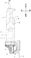
次に、本発明の実施形態を図1〜図5に基づいて説明する。図1は、本実施形態に係るスイッチ10を備えた電動工具1を示している。この電動工具1は、手持ち式のディスクグラインダであって、工具本体部2とギヤヘッド3とハンドル部4を備えている。工具本体部2の前部にギヤヘッド3が結合され、後部にハンドル部4が一体に設けられている。
工具本体部2には、電動モータ5が内装されている。電動モータ5の回転出力はギヤヘッド3に内装した歯車列6で減速された後スピンドル7に出力される。スピンドル7の先端に円形の砥石8が装着されている。
ハンドル部4は、使用者が片手で把持し易い太さと長さを有するハンドルケース4aを主体とするもので、工具本体部2の後部から後方へ延びている。ハンドル部4の後端部に、電力供給用の電源コード9が引き込まれている。工具本体部2の電動モータ5は、この電源コード9で供給される電力を電源として起動する。
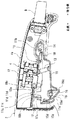
このハンドル部4の下面側に、本実施形態のスイッチ10が設けられている。本実施形態のスイッチ10の詳細が図2〜図5に示されている。このスイッチ10は、ハンドルケース4aの内部に固定したスイッチベース19と、このスイッチベース19に対して上下に傾動操作可能に支持されたスイッチレバー11と、このスイッチレバー11の操作によってオン、オフされるスイッチ本体12を備えている。
スイッチ本体12は、スイッチベース19とハンドルケース4aとの間に挟まれた状態に取り付けられて、ハンドルケース4aのほぼ中央に内装されている。スイッチベース19のほぼ中央に設けた窓部19aを経てスイッチ本体12の作動ノブ12aが下方(スイッチレバー11側)に向けられている。スイッチ本体12は、この作動ノブ12aが上方へ押し込まれるとオンし、ばね付勢力によってこの作動ノブ12aが下方へ突き出されるとオフする。スイッチ本体12がオンすると電動モータ5を起動するための電源回路がオンする。スイッチ本体12がオフすると、電動モータ5が停止される。このスイッチ本体12及び電源回路については公知の技術であり、本実施形態において特に変更を要しない。
本実施形態は、このスイッチ本体12をオンオフさせるスイッチレバー11及びスイッチレバー11の動作を規制するロックオン機構とロックオフ機構に特徴を有している。
Next, an embodiment of the present invention will be described with reference to FIGS. FIG. 1 shows an electric tool 1 including a
An electric motor 5 is built in the
The
The
The
The present embodiment is characterized by a
スイッチレバー11は、概ねスイッチベース19の下方に沿って前後に延びる状態で支持されている。スイッチレバー11は、その後部が支軸14を介してスイッチベース19の後部に結合されて上下に傾動操作可能に支持されている。この支軸14は、スイッチレバー11の後部に設けた前後に長い長溝孔11b内に挿通されている。このため、スイッチレバー11は、この支軸14を中心にして上下に傾動操作可能であるとともに、前後方向に一定の範囲でスライド操作可能に設けられている。
スイッチレバー11の前部側の左右側部には、左右一対の規制アーム部11c,11cが設けられている。両規制アーム部11c,11cは相互に平行な状態で上方へ延びている。両規制アーム部11c,11cの上端部には、それぞれ係合爪11dが設けられている。一方、スイッチベース19の前部には、上記の規制アーム部11c,11cに対応して2つの挿通溝孔19b,19bが設けられている。両挿通溝孔19b,19bは、相互に平行で前後に長く形成されている。この両挿通溝孔19b,19bに対してそれぞれスイッチレバー11の両規制アーム部11c,11cがそれぞれ下側から上方へ向けて挿通されて、当該スイッチレバー11がスイッチベース19に組み付けられている。両規制アーム部11c,11cの係合爪11d,11dがそれぞれスイッチベース19の上面に係合することによって、当該両規制アーム部11c,11cの挿通溝孔19b,19bからの抜け出しが規制されている。
両規制アーム部11c,11cがそれぞれ挿通溝孔19b内で上下に進退可能な範囲で当該スイッチレバー11がスイッチベース19に対して上下に傾動操作可能となっている。また、両規制アーム部11c,11cがそれぞれ挿通溝孔19b内で移動可能な範囲で当該スイッチレバー11がスイッチベース19に対して前後にスライド操作可能となっている。
スイッチレバー11とスイッチベース19との間には、2つの圧縮ばね13,18(図5では省略されている)が介装されている。上下方向に介装した圧縮ばね13によってスイッチレバー11は下側のオフ位置側へ傾動する方向(矢印C方向とは反対方向)に付勢されている。前後方向に介装した圧縮ばね18によってスイッチレバー11は後ろ側のロックオフ位置側へスライドする方向(矢印A方向とは反対方向)に付勢されている。
The
A pair of left and right restricting
The
Two compression springs 13 and 18 (not shown in FIG. 5) are interposed between the
スイッチレバー11には、ロックオン機構とロックオフ機構が併設されている。ロックオン機構は、スイッチレバー11をオン位置にロックする機能を有し、ロックオフ機構は、スイッチレバー11をオフ位置にロックする機能を有している。両機構は、相互に異なる操作部材を操作することによりロックオフ状態が解除され、またロックオン状態に切り換えられる。本実施形態では、スイッチレバー11をスライド操作することによりロックオフ機構の解除操作がなされ、後述するロックオン操作部材15を操作することによりロックオン状態への切り換えがなされる。
ロックオン操作部材15は、スイッチレバー11の前側に支持されている。このロックオン操作部材15の先端部15bはスイッチレバー11の下面に設けた窓部11aを経て下方へ突き出されている。このロックオン操作部材15は支軸部15aを介して前後に傾動操作可能に支持されている。このロックオン操作部材15は、捩りばね16によって図2において反時計回り方向であってその先端部15bを後ろ側(ロックオン解除位置側)に変位させる方向に付勢されている。ロックオン操作部材15の前部には、係合アーム部15cが一体に設けられている。この係合アーム部15cは上方に延びている。この係合アーム部15cの上部には、ロックオン爪15dが一体に設けられている。このロックオン爪15dは、後ろ側に張り出す状態に設けられている。
この係合アーム部15cに対応して、スイッチベース19の前部にはロックアーム17が一体に設けられている。このロックアーム17は、スイッチベース19の下面から下方へ延びる状態に設けられている。このロックベース17の前面下部には、ロック爪17aが一体に設けられている。
The
The lock-on
Corresponding to the
以上のように構成した本実施形態のスイッチ10によれば、図2に示すように使用者がスイッチレバー11を何ら操作しない状態では、当該スイッチレバー11が圧縮ばね13の付勢力によって下側のオフ位置に位置し、かつ圧縮ばね18の付勢力によって後ろ側のロックオフ位置に位置する。スイッチレバー11がオフ位置に位置する状態では、ロックオン操作部材15が捩りばね16の付勢力によってその先端部15bを後ろ側へ変位させたロックオン解除位置に保持される。
ロックオン操作部材15がロックオン解除位置に位置する初期状態では、その係合アーム部15cの真上にロックアーム17が位置する。このため、このロックオフ位置では、スイッチレバー11を後ろ側のロックオフ位置においてオン位置側(上方)へ傾動操作しようとしても係合アーム部15cの上方への変位がロックアーム17によって規制されるため、スイッチレバー11をオン位置側(図3中白抜きの矢印Cで示す方向)へ傾動操作することができない(ロックオフ状態)。このロックオフ状態によって、スイッチレバー11の不用意なオン操作が防止される。
これに対して図3に示すようにスイッチレバー11を圧縮ばね18に抗して白抜きの矢印Aで示す方向へスライド操作すると、係合アーム部15cがロックアーム17に対して前側へ退避するため、スイッチレバー11をオン位置側(矢印C方向)へ傾動操作することができる(ロックオフ解除状態)。こうしてロックオフ状態を解除した後に当該スイッチレバー11の握り込みを強くしてそのままオン位置側(白抜き矢印C方向)に傾動操作すると、作動ノブ12aが押し込まれてスイッチ本体12がオンし、従って電動モータ5が起動する。
使用者が指先による当該スイッチレバー11のオン位置側への傾動操作を止めると、スイッチレバー11は圧縮ばね13によって下方のオフ位置に戻される。スイッチレバー11をオフ位置に戻した後、さらに使用者が当該スイッチレバー11の前側へのスライド操作を解除すると当該スイッチレバー11は圧縮ばね18によって後ろ側のロックオフ位置に戻される。スイッチレバー11がロックオフ位置に戻されると、係合アーム15cがロックアーム17の直下に位置するため当該スイッチレバー11のオン位置側への引き操作が禁止されたロックオフ状態に戻される。
According to the
In the initial state where the lock-on
On the other hand, as shown in FIG. 3, when the
When the user stops the tilting operation of the
以上のロックオフ機能に加えて本実施形態のスイッチ10はロックオン機能を備えている。図3に示すように、スイッチレバー11を白抜き矢印Aで示すロックオフ解除位置にスライド操作した状態でスイッチレバー11を白抜き矢印Cで示すオン位置に傾動操作することによりスイッチ本体12をオンして電動モータ5を起動させることができる。その後、図4に示すようにロック操作部材15を白抜き矢印Bで示すロックオン位置側(その先端部15bを前側へ変位させる方向)に傾動操作する。
このロックオン操作により、係合アーム部15cのロックオン爪15dが、ロックアーム17のロック爪17aの上方へ進入する。このため、ロックオン操作部材15のロックオン操作を保持しつつスイッチレバー11のオン位置側への握り込みを弱くすると、スイッチレバー11に対する圧縮ばね13の付勢力によってロックオン爪15dがロックアーム17のロック爪17aに対して上側から押圧されるように係合される。ロックアーム17のロック爪17aに対して係合アーム部15cのロックオン爪15dが上側から係合されるため、ロック操作部材15がロックオン位置に保持されるとともに、スイッチレバー11のオフ位置側への傾動が規制された状態となる。
スイッチレバー11のオフ位置側への傾動が規制されてオン位置に保持されるため、スイッチ本体12はオン状態に保持され、従って電動モータ5が起動状態にロックされる。スイッチレバー11がオン位置にロックされるため、使用者は当該スイッチレバー11を引き操作することなく電動モータ5を起動状態にロックすることができ、従ってハンドル部4を把持して楽に作業を行うことができる。
In addition to the above lock-off function, the
By this lock-on operation, the lock-on
Since the tilting of the
このロックオン状態から、使用者がスイッチレバー11を再度上方へ握り込み操作すると、ロック操作部材15のロックオン爪15dが上方へ変位してロックアーム17のロック爪17aに対する係合状態が解除されるため、ロック操作部材15が捩りばね16の付勢力によってその先端部15bを後ろ側へ変位させる方向(図において反時計回り方向、ロックオン解除位置側)に戻される。図3に示すようにロック操作部材15がロックオン解除位置に戻されると、スイッチレバー11を下方のオフ位置側に戻すことができる。スイッチレバー11をオフ位置側に戻してスイッチ本体12がオフされた後に、当該スイッチレバー11の前側へのスライド操作を止めると当該スイッチレバー11は圧縮ばね18の付勢力によって後ろ側のロックオフ位置に戻される。
図2に示すようにスイッチレバー11が後ろ側のロックオフ位置へ戻されると、ロック操作部材15の係合アーム部15cが再びロックアーム17の直下に位置する状態となるため、当該スイッチ10が初期状態のロックオフ状態に戻される。
以上説明したように本実施形態のスイッチ10によれば、スイッチレバー15を図3中白抜き矢印Aで示すロックオフ解除方向へスライド操作することにより、当該スイッチレバー11のロックオフ状態を解除することができる。また、スイッチレバー11をオン位置に保持した状態で、ロック操作部材15を図4中白抜き矢印Bで示すロックオン方向へ傾動操作することによりスイッチレバー11をロックオン状態に切り換えることができる。このようにロックオフ機構を解除するために操作する部材(スイッチレバー11)と、ロックオン機構を有効にするために操作する部材(ロック操作部材15)が異なる部材であるので、使用者はロックオフ解除操作とロックオン切り換え操作とを明確に区別して操作することができる。このため、ロックオフ状態を解除操作した後、無意識のうちにロックオン状態への切り換え操作がなされてしまうことがなく、この点で使用者の操作意志が明確に反映されるスイッチ10とすることができる。
When the user grips the
As shown in FIG. 2, when the
As described above, according to the
以上説明した実施形態には種々変更を加えることができる。例えば、スイッチ10のロックオフ状態を解除するための操作部材としてスイッチレバー11を例示したが、別の操作部材を設けてロックオフ状態を解除する構成としてもよい。
また、ロックオフ状態を解除するためにスイッチレバー11をスライド操作する構成を例示したが、上記別の操作部材による場合にはスライド操作に代えて傾動操作によりロックオフ状態を解除する構成としてもよい。
さらに、スイッチレバー11とは別に設けた操作部材の操作によってロックオフ状態を解除し、その後スライドレバー11の例えば前側あるいは後ろ側へのスライド操作によってロックオン状態に切り換える構成としてもよい。
また、電動工具としてディスクグラインダを例示したが、本発明に係るスイッチは、例えば穴明け加工用の電気ドリル等のその他の電動工具のスイッチとして広く適用することができる。
Various modifications can be made to the embodiment described above. For example, although the
In addition, the configuration in which the
Further, the lock-off state may be released by operating an operation member provided separately from the
Further, although the disk grinder is exemplified as the electric tool, the switch according to the present invention can be widely applied as a switch of other electric tools such as an electric drill for drilling.
1…電動工具(ディスクグラインダ)
2…工具本体部
4…ハンドル部、4a…ハンドルケース
5…電動モータ
8…砥石
10…スイッチ
11…スイッチレバー
11a…窓部、11b…長溝孔、11c…規制アーム部、11d…係合爪
12…スイッチ本体、12a…作動ノブ
13…圧縮ばね
14…支軸
15…ロックオン操作部材
15a…支軸部、15b…先端部、15c…係合アーム部、15d…ロックオン爪
17…ロックアーム、17a…ロック爪、17b…係合突部
18…圧縮ばね
19…スイッチベース、19a…窓部
1 ... Electric tool (disc grinder)
DESCRIPTION OF
Claims (2)
前記ロックオン操作部材は、前記スイッチレバーに移動操作可能に設けられており、
前記スイッチレバーを後側にスライドさせた初期位置では前記ロックオン解除位置に位置するロックオン操作部材により当該スイッチレバーの前記オン位置側への傾動操作が規制されてロックオフ状態とされ、該ロックオフ状態は前記スイッチレバーを前側にスライドさせることにより解除されて当該スイッチレバーを前記オン位置側に傾動操作可能となり、該スイッチレバーを前記オン位置側に傾動操作した状態で前記ロックオン操作部材を前記ロックオン位置に移動操作して該スイッチレバーを前記オン位置にロックしたロックオン状態とする構成としたスイッチ。 A switch lever that can be tilted up and down between an on position for starting the electric tool and an off position for stopping the electric tool and can be slid in the front-rear direction, a lock on position that locks the switch lever in the on position, and the lock on A switch having a lock-on operation member capable of moving between a lock-on release position for releasing the state ,
The lock-on operation member is provided on the switch lever so as to be movable.
In the initial position where the switch lever is slid rearward, the lock-on operation member located at the lock-on release position restricts the tilting operation of the switch lever toward the on-position side to enter the lock-off state. The off-state is released by sliding the switch lever forward, so that the switch lever can be tilted to the on-position side, and the lock-on operation member is moved in a state in which the switch lever is tilted to the on-position side. A switch configured to be in a lock-on state in which the switch lever is locked at the on position by moving to the lock on position .
Priority Applications (7)
| Application Number | Priority Date | Filing Date | Title |
|---|---|---|---|
| JP2009014081A JP5265397B2 (en) | 2009-01-26 | 2009-01-26 | Power tool switch |
| US12/654,686 US8198560B2 (en) | 2009-01-09 | 2009-12-29 | Switch devices for power tools |
| RU2009149719/02A RU2508184C2 (en) | 2009-01-09 | 2009-12-30 | Electric tool switches |
| CN201310141752.5A CN103280342B (en) | 2009-01-09 | 2010-01-08 | Switch devices for power tools |
| EP10000123.9A EP2207191B1 (en) | 2009-01-09 | 2010-01-08 | Switch devices for power tools |
| CN2010100002969A CN101791777B (en) | 2009-01-09 | 2010-01-08 | Switch device for electric tool |
| BRPI1000075-5A BRPI1000075B1 (en) | 2009-01-09 | 2010-01-11 | SWITCH DEVICES FOR POWER TOOLS |
Applications Claiming Priority (1)
| Application Number | Priority Date | Filing Date | Title |
|---|---|---|---|
| JP2009014081A JP5265397B2 (en) | 2009-01-26 | 2009-01-26 | Power tool switch |
Publications (2)
| Publication Number | Publication Date |
|---|---|
| JP2010167542A JP2010167542A (en) | 2010-08-05 |
| JP5265397B2 true JP5265397B2 (en) | 2013-08-14 |
Family
ID=42700156
Family Applications (1)
| Application Number | Title | Priority Date | Filing Date |
|---|---|---|---|
| JP2009014081A Active JP5265397B2 (en) | 2009-01-09 | 2009-01-26 | Power tool switch |
Country Status (1)
| Country | Link |
|---|---|
| JP (1) | JP5265397B2 (en) |
Families Citing this family (6)
| Publication number | Priority date | Publication date | Assignee | Title |
|---|---|---|---|---|
| JP5548078B2 (en) * | 2010-09-15 | 2014-07-16 | 株式会社マキタ | Switch mechanism seal structure and power tool |
| JP5707267B2 (en) * | 2011-07-22 | 2015-04-22 | 株式会社マキタ | Electric tool |
| JP6803157B2 (en) * | 2016-06-24 | 2020-12-23 | 株式会社マキタ | Electric tool |
| WO2018230707A1 (en) * | 2017-06-16 | 2018-12-20 | 工機ホールディングス株式会社 | Electric tool |
| EP3503145B1 (en) * | 2017-12-22 | 2023-04-19 | Defond Electech Co., Ltd | A locking system for use with a trigger assembly of an electrical device |
| DE102020213232A1 (en) * | 2020-10-20 | 2022-04-21 | Robert Bosch Gesellschaft mit beschränkter Haftung | Hand tool with at least one operating unit |
Family Cites Families (7)
| Publication number | Priority date | Publication date | Assignee | Title |
|---|---|---|---|---|
| JP2606445Y2 (en) * | 1993-01-27 | 2000-11-06 | 株式会社マキタ | Switch structure of portable power tool |
| JP2977076B2 (en) * | 1996-03-01 | 1999-11-10 | リョービ株式会社 | Power tool switch mechanism |
| JP4005653B2 (en) * | 1996-11-29 | 2007-11-07 | 瓜生製作株式会社 | Pneumatic tool valve device |
| JPH11277462A (en) * | 1998-03-27 | 1999-10-12 | Makita Corp | Switch mechanism for power tool |
| JPH11347968A (en) * | 1998-06-09 | 1999-12-21 | Makita Corp | Switch mechanism of power tool |
| JP2001256858A (en) * | 2000-03-09 | 2001-09-21 | Satori Electric Co Ltd | Electric switch |
| JP4241810B2 (en) * | 2006-11-27 | 2009-03-18 | パナソニック電工株式会社 | Electric tool |
-
2009
- 2009-01-26 JP JP2009014081A patent/JP5265397B2/en active Active
Also Published As
| Publication number | Publication date |
|---|---|
| JP2010167542A (en) | 2010-08-05 |
Similar Documents
| Publication | Publication Date | Title |
|---|---|---|
| US8198560B2 (en) | Switch devices for power tools | |
| CN106625143B (en) | Electric tool | |
| JP5208775B2 (en) | Power tool switch | |
| JP4507211B2 (en) | Driving machine | |
| JP5707267B2 (en) | Electric tool | |
| JP5265397B2 (en) | Power tool switch | |
| JP4786774B2 (en) | Electric tool | |
| US10614977B2 (en) | Hand-held tool machine | |
| JP6895093B2 (en) | Electric tool | |
| CN101027166A (en) | Lockable trigger button for hammer drill | |
| EP1518629A1 (en) | Clamping apparatus for a tool component and an improved scrolling mechanism | |
| JP6026323B2 (en) | Electric tool | |
| JP5465405B2 (en) | Tabletop cutting machine | |
| EP3974110B1 (en) | Switch assembly and power tool | |
| WO2007088373A1 (en) | Power tool with removable handle portion | |
| CN105269506B (en) | Electric tool with rotation direction switcher | |
| US7767918B2 (en) | Power tool | |
| RU2434731C2 (en) | Electrical tool like angle grinding machine | |
| AU2015287069A1 (en) | Electric power tool having a slide switch | |
| JP4541031B2 (en) | Electric tool | |
| JP2002113703A (en) | Electric tool | |
| JP7596157B2 (en) | Switch mechanism for use in electric power tool and electric power tool | |
| JP4579008B2 (en) | Power tool storage box | |
| JP6665945B2 (en) | Power tool |
Legal Events
| Date | Code | Title | Description |
|---|---|---|---|
| A621 | Written request for application examination |
Free format text: JAPANESE INTERMEDIATE CODE: A621 Effective date: 20110805 |
|
| A131 | Notification of reasons for refusal |
Free format text: JAPANESE INTERMEDIATE CODE: A131 Effective date: 20130205 |
|
| A521 | Request for written amendment filed |
Free format text: JAPANESE INTERMEDIATE CODE: A523 Effective date: 20130321 |
|
| TRDD | Decision of grant or rejection written | ||
| A01 | Written decision to grant a patent or to grant a registration (utility model) |
Free format text: JAPANESE INTERMEDIATE CODE: A01 Effective date: 20130423 |
|
| A61 | First payment of annual fees (during grant procedure) |
Free format text: JAPANESE INTERMEDIATE CODE: A61 Effective date: 20130501 |
|
| R150 | Certificate of patent or registration of utility model |
Free format text: JAPANESE INTERMEDIATE CODE: R150 Ref document number: 5265397 Country of ref document: JP Free format text: JAPANESE INTERMEDIATE CODE: R150 |
|
| R250 | Receipt of annual fees |
Free format text: JAPANESE INTERMEDIATE CODE: R250 |
|
| R250 | Receipt of annual fees |
Free format text: JAPANESE INTERMEDIATE CODE: R250 |
|
| R250 | Receipt of annual fees |
Free format text: JAPANESE INTERMEDIATE CODE: R250 |
|
| R250 | Receipt of annual fees |
Free format text: JAPANESE INTERMEDIATE CODE: R250 |
|
| R250 | Receipt of annual fees |
Free format text: JAPANESE INTERMEDIATE CODE: R250 |
|
| R250 | Receipt of annual fees |
Free format text: JAPANESE INTERMEDIATE CODE: R250 |
|
| R250 | Receipt of annual fees |
Free format text: JAPANESE INTERMEDIATE CODE: R250 |
|
| R250 | Receipt of annual fees |
Free format text: JAPANESE INTERMEDIATE CODE: R250 |
|
| R250 | Receipt of annual fees |
Free format text: JAPANESE INTERMEDIATE CODE: R250 |
|
| R250 | Receipt of annual fees |
Free format text: JAPANESE INTERMEDIATE CODE: R250 |