JP5264763B2 - Shoulder joint implant - Google Patents
Shoulder joint implant Download PDFInfo
- Publication number
- JP5264763B2 JP5264763B2 JP2009539462A JP2009539462A JP5264763B2 JP 5264763 B2 JP5264763 B2 JP 5264763B2 JP 2009539462 A JP2009539462 A JP 2009539462A JP 2009539462 A JP2009539462 A JP 2009539462A JP 5264763 B2 JP5264763 B2 JP 5264763B2
- Authority
- JP
- Japan
- Prior art keywords
- intermediate element
- metal substructure
- implant
- shell
- pyrocarbon shell
- Prior art date
- Legal status (The legal status is an assumption and is not a legal conclusion. Google has not performed a legal analysis and makes no representation as to the accuracy of the status listed.)
- Expired - Fee Related
Links
Images


Classifications
-
- A—HUMAN NECESSITIES
- A61—MEDICAL OR VETERINARY SCIENCE; HYGIENE
- A61F—FILTERS IMPLANTABLE INTO BLOOD VESSELS; PROSTHESES; DEVICES PROVIDING PATENCY TO, OR PREVENTING COLLAPSING OF, TUBULAR STRUCTURES OF THE BODY, e.g. STENTS; ORTHOPAEDIC, NURSING OR CONTRACEPTIVE DEVICES; FOMENTATION; TREATMENT OR PROTECTION OF EYES OR EARS; BANDAGES, DRESSINGS OR ABSORBENT PADS; FIRST-AID KITS
- A61F2/00—Filters implantable into blood vessels; Prostheses, i.e. artificial substitutes or replacements for parts of the body; Appliances for connecting them with the body; Devices providing patency to, or preventing collapsing of, tubular structures of the body, e.g. stents
- A61F2/02—Prostheses implantable into the body
- A61F2/30—Joints
- A61F2/40—Joints for shoulders
- A61F2/4014—Humeral heads or necks; Connections of endoprosthetic heads or necks to endoprosthetic humeral shafts
-
- A—HUMAN NECESSITIES
- A61—MEDICAL OR VETERINARY SCIENCE; HYGIENE
- A61F—FILTERS IMPLANTABLE INTO BLOOD VESSELS; PROSTHESES; DEVICES PROVIDING PATENCY TO, OR PREVENTING COLLAPSING OF, TUBULAR STRUCTURES OF THE BODY, e.g. STENTS; ORTHOPAEDIC, NURSING OR CONTRACEPTIVE DEVICES; FOMENTATION; TREATMENT OR PROTECTION OF EYES OR EARS; BANDAGES, DRESSINGS OR ABSORBENT PADS; FIRST-AID KITS
- A61F2/00—Filters implantable into blood vessels; Prostheses, i.e. artificial substitutes or replacements for parts of the body; Appliances for connecting them with the body; Devices providing patency to, or preventing collapsing of, tubular structures of the body, e.g. stents
- A61F2/02—Prostheses implantable into the body
- A61F2/30—Joints
- A61F2/3094—Designing or manufacturing processes
-
- A—HUMAN NECESSITIES
- A61—MEDICAL OR VETERINARY SCIENCE; HYGIENE
- A61F—FILTERS IMPLANTABLE INTO BLOOD VESSELS; PROSTHESES; DEVICES PROVIDING PATENCY TO, OR PREVENTING COLLAPSING OF, TUBULAR STRUCTURES OF THE BODY, e.g. STENTS; ORTHOPAEDIC, NURSING OR CONTRACEPTIVE DEVICES; FOMENTATION; TREATMENT OR PROTECTION OF EYES OR EARS; BANDAGES, DRESSINGS OR ABSORBENT PADS; FIRST-AID KITS
- A61F2/00—Filters implantable into blood vessels; Prostheses, i.e. artificial substitutes or replacements for parts of the body; Appliances for connecting them with the body; Devices providing patency to, or preventing collapsing of, tubular structures of the body, e.g. stents
- A61F2/02—Prostheses implantable into the body
- A61F2/30—Joints
- A61F2002/30001—Additional features of subject-matter classified in A61F2/28, A61F2/30 and subgroups thereof
- A61F2002/30316—The prosthesis having different structural features at different locations within the same prosthesis; Connections between prosthetic parts; Special structural features of bone or joint prostheses not otherwise provided for
- A61F2002/30329—Connections or couplings between prosthetic parts, e.g. between modular parts; Connecting elements
- A61F2002/30331—Connections or couplings between prosthetic parts, e.g. between modular parts; Connecting elements made by longitudinally pushing a protrusion into a complementarily-shaped recess, e.g. held by friction fit
- A61F2002/30332—Conically- or frustoconically-shaped protrusion and recess
-
- A—HUMAN NECESSITIES
- A61—MEDICAL OR VETERINARY SCIENCE; HYGIENE
- A61F—FILTERS IMPLANTABLE INTO BLOOD VESSELS; PROSTHESES; DEVICES PROVIDING PATENCY TO, OR PREVENTING COLLAPSING OF, TUBULAR STRUCTURES OF THE BODY, e.g. STENTS; ORTHOPAEDIC, NURSING OR CONTRACEPTIVE DEVICES; FOMENTATION; TREATMENT OR PROTECTION OF EYES OR EARS; BANDAGES, DRESSINGS OR ABSORBENT PADS; FIRST-AID KITS
- A61F2/00—Filters implantable into blood vessels; Prostheses, i.e. artificial substitutes or replacements for parts of the body; Appliances for connecting them with the body; Devices providing patency to, or preventing collapsing of, tubular structures of the body, e.g. stents
- A61F2/02—Prostheses implantable into the body
- A61F2/30—Joints
- A61F2002/30001—Additional features of subject-matter classified in A61F2/28, A61F2/30 and subgroups thereof
- A61F2002/30316—The prosthesis having different structural features at different locations within the same prosthesis; Connections between prosthetic parts; Special structural features of bone or joint prostheses not otherwise provided for
- A61F2002/30329—Connections or couplings between prosthetic parts, e.g. between modular parts; Connecting elements
- A61F2002/30476—Connections or couplings between prosthetic parts, e.g. between modular parts; Connecting elements locked by an additional locking mechanism
- A61F2002/30495—Connections or couplings between prosthetic parts, e.g. between modular parts; Connecting elements locked by an additional locking mechanism using a locking ring
-
- A—HUMAN NECESSITIES
- A61—MEDICAL OR VETERINARY SCIENCE; HYGIENE
- A61F—FILTERS IMPLANTABLE INTO BLOOD VESSELS; PROSTHESES; DEVICES PROVIDING PATENCY TO, OR PREVENTING COLLAPSING OF, TUBULAR STRUCTURES OF THE BODY, e.g. STENTS; ORTHOPAEDIC, NURSING OR CONTRACEPTIVE DEVICES; FOMENTATION; TREATMENT OR PROTECTION OF EYES OR EARS; BANDAGES, DRESSINGS OR ABSORBENT PADS; FIRST-AID KITS
- A61F2/00—Filters implantable into blood vessels; Prostheses, i.e. artificial substitutes or replacements for parts of the body; Appliances for connecting them with the body; Devices providing patency to, or preventing collapsing of, tubular structures of the body, e.g. stents
- A61F2/02—Prostheses implantable into the body
- A61F2/30—Joints
- A61F2002/30001—Additional features of subject-matter classified in A61F2/28, A61F2/30 and subgroups thereof
- A61F2002/30316—The prosthesis having different structural features at different locations within the same prosthesis; Connections between prosthetic parts; Special structural features of bone or joint prostheses not otherwise provided for
- A61F2002/30329—Connections or couplings between prosthetic parts, e.g. between modular parts; Connecting elements
- A61F2002/30476—Connections or couplings between prosthetic parts, e.g. between modular parts; Connecting elements locked by an additional locking mechanism
- A61F2002/305—Snap connection
-
- A—HUMAN NECESSITIES
- A61—MEDICAL OR VETERINARY SCIENCE; HYGIENE
- A61F—FILTERS IMPLANTABLE INTO BLOOD VESSELS; PROSTHESES; DEVICES PROVIDING PATENCY TO, OR PREVENTING COLLAPSING OF, TUBULAR STRUCTURES OF THE BODY, e.g. STENTS; ORTHOPAEDIC, NURSING OR CONTRACEPTIVE DEVICES; FOMENTATION; TREATMENT OR PROTECTION OF EYES OR EARS; BANDAGES, DRESSINGS OR ABSORBENT PADS; FIRST-AID KITS
- A61F2/00—Filters implantable into blood vessels; Prostheses, i.e. artificial substitutes or replacements for parts of the body; Appliances for connecting them with the body; Devices providing patency to, or preventing collapsing of, tubular structures of the body, e.g. stents
- A61F2/02—Prostheses implantable into the body
- A61F2/30—Joints
- A61F2002/30001—Additional features of subject-matter classified in A61F2/28, A61F2/30 and subgroups thereof
- A61F2002/30316—The prosthesis having different structural features at different locations within the same prosthesis; Connections between prosthetic parts; Special structural features of bone or joint prostheses not otherwise provided for
- A61F2002/30535—Special structural features of bone or joint prostheses not otherwise provided for
- A61F2002/30604—Special structural features of bone or joint prostheses not otherwise provided for modular
- A61F2002/30616—Sets comprising a plurality of prosthetic parts of different sizes or orientations
-
- A—HUMAN NECESSITIES
- A61—MEDICAL OR VETERINARY SCIENCE; HYGIENE
- A61F—FILTERS IMPLANTABLE INTO BLOOD VESSELS; PROSTHESES; DEVICES PROVIDING PATENCY TO, OR PREVENTING COLLAPSING OF, TUBULAR STRUCTURES OF THE BODY, e.g. STENTS; ORTHOPAEDIC, NURSING OR CONTRACEPTIVE DEVICES; FOMENTATION; TREATMENT OR PROTECTION OF EYES OR EARS; BANDAGES, DRESSINGS OR ABSORBENT PADS; FIRST-AID KITS
- A61F2/00—Filters implantable into blood vessels; Prostheses, i.e. artificial substitutes or replacements for parts of the body; Appliances for connecting them with the body; Devices providing patency to, or preventing collapsing of, tubular structures of the body, e.g. stents
- A61F2/02—Prostheses implantable into the body
- A61F2/30—Joints
- A61F2/3094—Designing or manufacturing processes
- A61F2002/30971—Laminates, i.e. layered products
-
- A—HUMAN NECESSITIES
- A61—MEDICAL OR VETERINARY SCIENCE; HYGIENE
- A61F—FILTERS IMPLANTABLE INTO BLOOD VESSELS; PROSTHESES; DEVICES PROVIDING PATENCY TO, OR PREVENTING COLLAPSING OF, TUBULAR STRUCTURES OF THE BODY, e.g. STENTS; ORTHOPAEDIC, NURSING OR CONTRACEPTIVE DEVICES; FOMENTATION; TREATMENT OR PROTECTION OF EYES OR EARS; BANDAGES, DRESSINGS OR ABSORBENT PADS; FIRST-AID KITS
- A61F2/00—Filters implantable into blood vessels; Prostheses, i.e. artificial substitutes or replacements for parts of the body; Appliances for connecting them with the body; Devices providing patency to, or preventing collapsing of, tubular structures of the body, e.g. stents
- A61F2/02—Prostheses implantable into the body
- A61F2/30—Joints
- A61F2/40—Joints for shoulders
- A61F2/4014—Humeral heads or necks; Connections of endoprosthetic heads or necks to endoprosthetic humeral shafts
- A61F2002/4018—Heads or epiphyseal parts of humerus
-
- A—HUMAN NECESSITIES
- A61—MEDICAL OR VETERINARY SCIENCE; HYGIENE
- A61F—FILTERS IMPLANTABLE INTO BLOOD VESSELS; PROSTHESES; DEVICES PROVIDING PATENCY TO, OR PREVENTING COLLAPSING OF, TUBULAR STRUCTURES OF THE BODY, e.g. STENTS; ORTHOPAEDIC, NURSING OR CONTRACEPTIVE DEVICES; FOMENTATION; TREATMENT OR PROTECTION OF EYES OR EARS; BANDAGES, DRESSINGS OR ABSORBENT PADS; FIRST-AID KITS
- A61F2220/00—Fixations or connections for prostheses classified in groups A61F2/00 - A61F2/26 or A61F2/82 or A61F9/00 or A61F11/00 or subgroups thereof
- A61F2220/0025—Connections or couplings between prosthetic parts, e.g. between modular parts; Connecting elements
- A61F2220/0033—Connections or couplings between prosthetic parts, e.g. between modular parts; Connecting elements made by longitudinally pushing a protrusion into a complementary-shaped recess, e.g. held by friction fit
-
- A—HUMAN NECESSITIES
- A61—MEDICAL OR VETERINARY SCIENCE; HYGIENE
- A61F—FILTERS IMPLANTABLE INTO BLOOD VESSELS; PROSTHESES; DEVICES PROVIDING PATENCY TO, OR PREVENTING COLLAPSING OF, TUBULAR STRUCTURES OF THE BODY, e.g. STENTS; ORTHOPAEDIC, NURSING OR CONTRACEPTIVE DEVICES; FOMENTATION; TREATMENT OR PROTECTION OF EYES OR EARS; BANDAGES, DRESSINGS OR ABSORBENT PADS; FIRST-AID KITS
- A61F2310/00—Prostheses classified in A61F2/28 or A61F2/30 - A61F2/44 being constructed from or coated with a particular material
- A61F2310/00005—The prosthesis being constructed from a particular material
- A61F2310/00161—Carbon; Graphite
- A61F2310/00173—Graphite
-
- A—HUMAN NECESSITIES
- A61—MEDICAL OR VETERINARY SCIENCE; HYGIENE
- A61F—FILTERS IMPLANTABLE INTO BLOOD VESSELS; PROSTHESES; DEVICES PROVIDING PATENCY TO, OR PREVENTING COLLAPSING OF, TUBULAR STRUCTURES OF THE BODY, e.g. STENTS; ORTHOPAEDIC, NURSING OR CONTRACEPTIVE DEVICES; FOMENTATION; TREATMENT OR PROTECTION OF EYES OR EARS; BANDAGES, DRESSINGS OR ABSORBENT PADS; FIRST-AID KITS
- A61F2310/00—Prostheses classified in A61F2/28 or A61F2/30 - A61F2/44 being constructed from or coated with a particular material
- A61F2310/00389—The prosthesis being coated or covered with a particular material
- A61F2310/00574—Coating or prosthesis-covering structure made of carbon, e.g. of pyrocarbon
Abstract
Description
本出願は、2006年11月29日付で出願された米国仮特許出願番号第60/867,741号に基づく優先権を主張するものであり、本開示は引用により本明細書の一部を構成する。 This application claims priority from US Provisional Patent Application No. 60 / 867,741, filed Nov. 29, 2006, the disclosure of which is hereby incorporated by reference. To do.
人工肩関節の1つの種類は上腕頭の「新たな表面形成(resurfacing)」インプラントと呼ばれ、もう1つの種類は上腕頭「置換」インプラントと呼ばれる。上腕頭の新たな表面形成は、上腕頭の関節形成のための保存的手法であり、ドーム形状の薄壁シェル構造体を用いて上腕頭の表面を再仕上げすることにより達成される。前者のインプラントは、上腕骨への固定を達成するため、かつ既存の骨の大部分を保存するために、比較的短い中央ステムを有する。上腕頭置換においては、手術中に上腕頭の全体が切除されるが、上腕頭置換インプラントは、インプラントを上腕骨に固定するためにより長い骨髄ステムを有する。図1A、図1B、および図1Cは、現在用いられているインプラントを代表するこのような2つのインプラントを示す。 One type of shoulder prosthesis is called the “new resurfacing” implant of the humeral head, and the other type is called the humeral head “replacement” implant. The new surface formation of the humeral head is a conservative approach for articulating the humeral head and is accomplished by refinishing the surface of the humeral head using a dome-shaped thin-walled shell structure. The former implant has a relatively short central stem to achieve fixation to the humerus and to preserve the majority of existing bone. In humeral head replacement, the entire humeral head is resected during surgery, but the humeral head replacement implant has a longer bone marrow stem to secure the implant to the humerus. 1A, 1B, and 1C show two such implants that are representative of the implants currently in use.
背景情報として、肩関節は、関節窩と呼ばれる浅いソケットと共に関節を成す上腕骨の頭部により形成される。図2に示されるように、関節窩は肩甲骨の外側縁に位置する。上腕頭の新たな表面形成インプラントと置換インプラントは両方とも、関節全置換または関節半置換に用いることができる。関節全置換は、典型的には図3Aおよび図3Bに示されるように関節窩を置換するポリエチレン製ソケットを含む。 As background information, the shoulder joint is formed by the head of the humerus that articulates with a shallow socket called the glenoid. As shown in FIG. 2, the glenoid is located on the outer edge of the scapula. Both the new superficial implant and replacement implant of the humeral head can be used for total joint replacement or half joint replacement. Total joint replacement typically includes a polyethylene socket that replaces the glenoid as shown in FIGS. 3A and 3B.
関節窩まで露出させることは困難であるため、米国で行われる肩関節形成術の過半数は半関節形成術であり、しかも関節窩を構成する骨量は非常に限られているので、関節窩置換部品はしばしば外れることがある。その上、上腕頭置換インプラントの方が上腕頭の新たな表面形成インプラントよりも一般的に用いられている。 Because it is difficult to expose to the glenoid, the majority of shoulder arthroplasties performed in the United States are hemiarthroplasty, and the amount of bone that makes up the glenoid is very limited, so glenoid replacement Parts often come off. In addition, humeral head replacement implants are more commonly used than new surface-forming implants of the humeral head.
現在、関節全置換および関節半置換において用いられる上腕頭インプラント(上腕頭置換インプラントおよび新たな表面形成インプラントの両者)は、Co−Cr合金から作られている。しかしながら、今や、Co−Cr合金は関節組織(軟骨および骨)に損傷を与えることが認識されており、このことが、そのような半関節形成術の欠点となっている。パイロカーボンは生来の関節組織(軟骨および骨)に与える損傷が遥かに少ないことが示されており、従って、酸化アルミニウムまたはジルコニアのような金属またはセラミックスよりも優れた半関節形成術材料である。パイロカーボンは脆性材料であるため、それ自体Co−Cr合金ほど強固でも強靭でもないので、そのため強度性能の要件を満たすパイロカーボン製の上腕頭インプラント装置の設計が望まれる。 Currently, humeral head implants (both humeral head replacement implants and new surface-forming implants) used in total and half joint replacements are made from Co-Cr alloys. However, it is now recognized that Co—Cr alloys damage joint tissues (cartilage and bone), which is a drawback of such hemiarthroplasty. Pyrocarbon has been shown to be much less damaging to native joint tissues (cartilage and bone) and is therefore a hemiarthroplasty material superior to metals or ceramics such as aluminum oxide or zirconia. Since pyrocarbon is a brittle material, it itself is not as strong or tough as a Co—Cr alloy, and therefore, a design of a pyrocarbon humeral head implant device that meets the strength performance requirements is desired.
慎重な工学技術の使用によって、適合させる必要がある上腕頭に対して作用する通常の関節の反作用の力は体重の2倍になり得ることを言明している人工肩関節のための標準規格であるASTM F1378−05を満たす、パイロカーボン製上腕頭インプラントの設計が可能であることが見出された。通常の体重を180ポンドと仮定すると、上腕インプラントに対して作用する関節力は360ポンドとなり、最悪の状況では上腕頭インプラントに対してさらに一層大きな力がかかることになる。以下で説明する設計によって、これらの力に適合することができる。 A standard for prosthetic shoulder joints that states that with the use of careful engineering, the normal joint reaction force acting on the humeral head that needs to be adapted can be double the weight. It has been found that it is possible to design pyrocarbon humeral head implants that meet certain ASTM F1378-05. Assuming a normal weight of 180 pounds, the joint force acting on the brachial implant is 360 pounds, and in the worst case an even greater force is exerted on the brachial head implant. These forces can be accommodated by the design described below.
1つの特定の態様において、本発明は、整形外科用関節部の1つの骨部品の頭部に置換関節面を設けるためのインプラントを提供し、このインプラントは、球面の一部分である外面と、凹状の内面と、開口した基端底部とを有するパイロカーボンシェルと、凸状の末端面を有し、インプラントを骨の端部に形成された空洞内に固定するための手段をその基端部に有する金属下部構造体と、パイロカーボンシェルの開口した基端底部内への軸線方向の自身の挿入を可能にするほど十分に可撓性の中間要素であって、このシェルと中間要素とのサブアッセンブリーから中間要素が引き抜かれることを防止する締まり嵌めを作り出す中間要素とを備え、この要素と金属下部構造体は、金属下部構造体をサブアッセンブリーの中に完全に挿入できるようにさせるがそこからの金属下部構造体の引き抜きを防止する相互係合手段を有し、それにより、関節部における力がパイロカーボンシェルを介して金属下部構造体の凸面に圧縮するように伝達される。 In one particular aspect, the present invention provides an implant for providing a replacement joint surface on the head of one bone component of an orthopedic joint, the implant comprising an outer surface that is part of a spherical surface and a concave shape. A pyrocarbon shell having an inner surface and an open proximal bottom, a convex distal surface, and a means for securing the implant in a cavity formed at the end of the bone at the proximal end An intermediate element that is sufficiently flexible to permit insertion of the metal substructure and the pyrocarbon shell into the open proximal bottom of the pyrocarbon shell in an axial direction. An intermediate element that creates an interference fit that prevents the intermediate element from being pulled out of the assembly, and this element and the metal substructure can fully insert the metal substructure into the subassembly. But with interengagement means to prevent withdrawal of the metal substructure from it, so that the force at the joint is transmitted through the pyrocarbon shell to compress to the convex surface of the metal substructure. The
別の特定の態様において、本発明は、肩関節の上腕頭に置換関節面を設けるためのインプラントを提供し、このインプラントは、球体の一部である外側凸面と、凹状の内面と、開口した基端底部とを有するパイロカーボンシェルと、凸状の末端面を有し、インプラントを骨の端部に形成された空洞内に固定するための手段をその基端面に有する金属下部構造体と、パイロカーボンシェルの開口した基端底部内への軸線方向の自身の挿入を可能にするほど十分に可撓性であり、このシェルと中間要素とのサブアッセンブリーから中間要素が引き抜かれることを防止する締まり嵌めを作りだす、シェルの形状の中間要素であって、このシェルは、パイロカーボンシェルの内側凹面に実質的に当接する凸状外面部を有する中間要素とを備え、中間要素は、円柱状内面区画を有し、金属下部構造体は、中間要素の円筒面と近接するように調整をとられた円筒面部を有し、この要素および金属下部構造体は、金属下部構造体がサブアッセンブリーの中に完全に挿入されたときに互いに整列する対向する溝を円筒面内に有し、このインプラントは、金属下部構造体内の溝に完全に受け入れられ、金属下部構造体がサブアッセンブリーの中に前記のように挿入された後は、拡張して対向する溝の各々の中に部分的に存在する拡張性リテーナを備え、それにより、肩関節にかかる力が、パイロカーボンシェルを介して金属下部構造体の凸面に圧縮するように伝達される。 In another particular aspect, the present invention provides an implant for providing a replacement joint surface on the humeral head of a shoulder joint, the implant being open to an outer convex surface that is part of a sphere, a concave inner surface, and an open surface. A pyrocarbon shell having a proximal bottom, a metal substructure having a convex distal surface and means for securing the implant in a cavity formed at the end of the bone at the proximal surface; It is flexible enough to allow its axial insertion into the open proximal bottom of the pyrocarbon shell, preventing the intermediate element from being pulled out of the shell and intermediate element subassembly. An intermediate element in the form of a shell that creates an interference fit, the shell comprising an intermediate element having a convex outer surface that substantially abuts the inner concave surface of the pyrocarbon shell. Has a cylindrical inner surface section, and the metal substructure has a cylindrical surface portion adjusted to be close to the cylindrical surface of the intermediate element, the element and metal substructure being a metal substructure Having opposing grooves in the cylindrical surface that align with each other when fully inserted into the subassembly, the implant is fully received in the grooves in the metal substructure, and the metal substructure is in the subassembly. After being inserted into the body as described above, it is provided with an expandable retainer that expands and partially resides in each of the opposing grooves so that the force on the shoulder joint is passed through the pyrocarbon shell. And transmitted to the convex surface of the metal substructure.
更なる特定の態様において、本発明は、整形外科的関節部の1つの骨部品に置換関節面を設けるためのインプラントを提供し、このインプラントは、球体の一部分である外面と、凹状の内面と、開口した基端底部とを有するパイロカーボンシェルと、凸状の末端面と、基端の円筒面部とを有し、インプラントを骨の端部に形成された空洞内に固定するための手段をその基端部に有する金属下部構造体と、パイロカーボンシェルの内側凹状ドーム形面と実質的に当接する凸状ドーム形外面末端部を有し、かつ基端の円筒状内面部を有する中間要素であって、パイロカーボンシェルの開口した基端底部内への軸線方向の挿入を可能にするほど十分に可撓性であり、このシェルと中間要素とのサブアッセンブリーから中間要素が引き抜かれることを防止する締まり嵌めを作り出す中間要素とを備え、金属下部構造体は、その円筒面が中間要素の円筒面と近接されるように中間要素と嵌合し、中間要素および金属下部構造体は、金属下部構造体をサブアッセンブリーの中に完全に挿入できるようにさせるがそこからの金属下部構造体の引き抜きを防止する相互係合手段を有し、それにより、関節部にかかる力が、パイロカーボンシェルおよび中間要素を介して金属下部構造体の凸面に圧縮するように伝達される。 In a further particular aspect, the present invention provides an implant for providing a replacement articular surface on one bone component of an orthopedic joint, the implant comprising an outer surface that is part of a sphere, a concave inner surface, A means for securing the implant in a cavity formed at the end of the bone, having a pyrocarbon shell having an open proximal bottom, a convex distal surface, and a proximal cylindrical surface; An intermediate element having a metal substructure at its proximal end, a convex dome-shaped outer surface distal end substantially in contact with the inner concave dome-shaped surface of the pyrocarbon shell, and a proximal cylindrical inner surface And is sufficiently flexible to allow axial insertion into the open proximal bottom of the pyrocarbon shell, so that the intermediate element is pulled out of the shell and intermediate element subassembly. An intermediate element that creates an interference fit that stops, the metal substructure is fitted with the intermediate element such that its cylindrical surface is in close proximity to the cylindrical surface of the intermediate element, and the intermediate element and the metal substructure are Having interengaging means to allow the substructure to be fully inserted into the subassembly but to prevent the metal substructure from being extracted therefrom, so that the force on the joint is controlled by the pyrocarbon shell And is transmitted to the convex surface of the metal substructure through the intermediate element.
人間の上腕頭は、半球体に近いものとして、即ち、図5に示されるような寸法関係を有する球状キャップとしてかなりよく表現され得る。Iannotti、J Bone Joint Surg(am)、1992年、第74巻、p.491−500(非特許文献1)は、人間の上腕頭の寸法は、R=28mm、W=55.4mm、およびH=24mmほどの大きさであり得ることを報告している。 The human humeral head can be expressed fairly well as a hemisphere, ie, a spherical cap having a dimensional relationship as shown in FIG. Iannotti, J Bone Joint Surg (am), 1992, vol. 74, p. 491-500 (Non-Patent Document 1) reports that the dimensions of a human humeral head can be as large as R = 28 mm, W = 55.4 mm, and H = 24 mm.
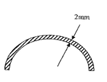
パイロカーボン部品は、一般に、化学蒸着法(CVD)を用いてグラファイト基材構造体上に熱分解炭素層を蒸着することによって製造される。熱分解炭素コーティングを所望の形状および寸法のグラファイト基材に施すために流動浸漬塗布が、しばしば、用いられる。コーティングされるグラファイト部品は、流動床の中で浮上され、これにより、基材上に蒸着される連続的な熱分解炭素コーティングを確実にする。重い部品は、それほど重くない部品よりも流動床で浮上させるのは困難なのでそのため、コーティングされる部品の質量をできるだけ減らすことが、有利である。図6Aに示されるように、R=28mmおよびW=55mmの寸法を有する球状キャップ形状の中実グラファイト基材部品は、約36.2ccの体積を有し、約64.4グラムの質量を有し得る。部品の質量は、中実の形態ではなく、図6Bに示されるように、薄壁のシェル形態を形成することによって著しく減らすことができる。W=55mm、H=24mm、および2mmのシェル厚さを有するグラファイトシェルは、約7.8ccの体積、および、約13.9グラムに相当する質量、即ち、類似の中実の形態よりも約78%少ない質量を有する。 Pyrocarbon components are generally manufactured by depositing a pyrolytic carbon layer on a graphite substrate structure using chemical vapor deposition (CVD). Fluid dip coating is often used to apply a pyrolytic carbon coating to a graphite substrate of the desired shape and dimensions. The graphite parts to be coated are floated in a fluidized bed, thereby ensuring a continuous pyrolytic carbon coating deposited on the substrate. Since heavy parts are more difficult to float in a fluidized bed than less heavy parts, it is therefore advantageous to reduce the mass of the part to be coated as much as possible. As shown in FIG. 6A, a spherical cap-shaped solid graphite substrate part having dimensions R = 28 mm and W = 55 mm has a volume of about 36.2 cc and a mass of about 64.4 grams. Can do. The mass of the part can be significantly reduced by forming a thin-walled shell configuration, as shown in FIG. 6B, rather than a solid configuration. A graphite shell having a shell thickness of W = 55 mm, H = 24 mm, and 2 mm has a volume of about 7.8 cc and a mass equivalent to about 13.9 grams, i.e. less than a similar solid form. Has 78% less mass.
要約すれば、実質的に小さい質量の基材をコーティングすることは、以下の利点を有する。 In summary, coating a substantially low mass substrate has the following advantages.
1.より質量の小さい部品ほど、より容易に流動浸漬塗布の中で浮上される。2.流動浸漬塗布において一度にコーティングすることができる部品の数は、コーティングされる部品の総質量によって制限されることがしばしばであり、即ち、連続塗布の最大総質量が存在する。個々の部品の質量が小さいほど、より多くの部品を一度にコーティングすることができるので、その結果、連続塗布のより高い効率が得られる。3.その結果得られる、質量が小さいグラファイト基材を有するコーティングされた部品では、熱分解炭素コーティングの熱膨張係数とグラファイト基材の熱膨張係数との差異の結果として固有にもたらされるコーティング後の残留歪みが低減されることになる。 1. Parts with lower mass are more easily floated in fluid dip coating. 2. The number of parts that can be coated at one time in fluid dip coating is often limited by the total mass of the parts to be coated, i.e. there is a maximum total mass for continuous application. The smaller the mass of individual parts, the more parts can be coated at one time, resulting in higher efficiency of continuous application. 3. The resulting coated part with a low mass graphite substrate inherently has a post-coating residual strain that is inherently the result of the difference between the thermal expansion coefficient of the pyrolytic carbon coating and that of the graphite substrate. Will be reduced.
関節面(支持部)としてのパイロカーボンシェルを用いて作られる上腕頭の置換インプラントは、パイロカーボンシェルを骨髄ステム構成部品に装着できるようにする構造体によってパイロカーボンシェルを支持すべきである。理想的には、ヘッド構成部品およびステム構成部品は、患者一人一人によって異なることが予想される解剖学的変化量に応じるように異なるサイズのヘッド構成部品と異なるサイズのステム構成部品とを組み立てることができるようにモジュール式とされる。当該技術分野で知られるように、他の適切な摩擦的相互連結および締まり嵌めを用いられてもよいけれど、このようなモジュール式解剖学的関節部用インプラントヘッド構成部品とステム構成部品とを連結する一般的かつ成功している手段は、テーパロック機構を採用している。金属下部構造体上に関節面をもたらすパイロカーボンシェルを支持することが、パイロカーボン表面仕上げされたヘッド構成部品をモジュール式金属ステムに接合するようにこのようなテーパロック機構等を用いる能力をもたらし、好ましい。しかしながら、ステムを含む一体型金属下部構造体は代替手段であるが、それほど望ましくはない。 A humeral head replacement implant made with a pyrocarbon shell as the articular surface (support) should support the pyrocarbon shell with a structure that allows the pyrocarbon shell to be attached to a bone marrow stem component. Ideally, the head and stem components should be assembled with different sized head components and different sized stem components to accommodate the anatomical variations expected to vary from patient to patient. To be modular. As is known in the art, other suitable frictional interconnections and interference fits may be used, but such modular anatomical joint head and stem components are connected. A common and successful means is to employ a taper lock mechanism. Supporting the pyrocarbon shell that provides the articulating surface on the metal substructure provides the ability to use such a taper lock mechanism to join the pyrocarbon surface-finished head component to the modular metal stem. ,preferable. However, an integral metal substructure that includes a stem is an alternative, but less desirable.
パイロカーボンは、脆性材料であり、他の脆性材料と同様に、引張よりも圧縮に遥かに強い。パイロカーボンシェル構造体と金属下部構造体との間で負荷を伝達する場合、パイロカーボン支持面が圧縮下で配されることを確実にする金属下部構造体に対してパイロカーボンシェルを取り付けるためのシステムを設計することにより、関節形成術で用いるためのインプラントにおけるパイロカーボン関節面の有効利用が、促進される。その金属下部構造体に対するパイロカーボンシェルの接合のための取付機構の設計は、また、一旦組み立てた後、アッセンブリーがばらばらにならないこと、即ち、分解しないことを確実にするものでなければならない。 Pyrocarbon is a brittle material and, like other brittle materials, is much more resistant to compression than tension. When transferring the load between the pyrocarbon shell structure and the metal substructure, to attach the pyrocarbon shell to the metal substructure, which ensures that the pyrocarbon support surface is arranged under compression Designing the system facilitates the effective use of the pyrocarbon articular surface in implants for use in arthroplasty. The design of the attachment mechanism for joining the pyrocarbon shell to the metal substructure must also ensure that the assembly does not fall apart, i.e. not disassemble, once assembled.
図7に示されるものは、ヘッド11の設計の1つの実施例である。これは、パイロカーボンシェル13、および、ポリエチレンライナのような中間要素15を介して中央の金属下部構造体17に圧縮下で接合力の伝達をもたらす。縮小(落込み)可能−拡張性のある割りリング型リテーナ19のような保持手段が、組み立てられた構成部品が分解しないようにそれらを互いに永続的にロックする。金属下部構造体17は、そのヘッドをモジュール式ステムに相互連結するように好ましくは、その基端の平坦面に雌型空洞26を含む。
Shown in FIG. 7 is one example of the design of the head 11. This provides a transmission of the bonding force under compression to the
図7からわかるように、中間要素15は、機械加工またはポリエチレンまたは他の適切な生体適合ポリマーまたはコポリマーで成形され得るシェル形状のオーバーオールライナ構造体(overall liner structure)である。その中間要素は、金属下部構造体17とパイロカーボンシェル13との間で嵌め合うものであり、パイロカーボンシェルの凹状の内面20全体に近接する外側凸状面を有する。パイロカーボンシェル13は、内側に突出したリップ21を、図示されるように締まり嵌め(IF)を形成するようにポリエチレンライナの縮小部分23と係合するその基部に有する。ポリエチレンライナ15の中央の内面25および金属下部構造体17の中央面27は、その頂部、即ち、末端領域ではドーム形状であるが、基部周縁部においては直線的な壁29、31を有する。それらの直線的な壁は、直円筒面であることが好ましい。相対向する溝33、35が、好ましい保持手段である平坦な割りリングリテーナ19を収容するようにポリエチレンライナおよび金属下部構造体に、それぞれ、配置されるが、分解を防ぐ他の保持機構が、代替的に用いられてもよい。
As can be seen from FIG. 7, the
複数の構成部品は、以下のように組み立てられる。最初に、ポリエチレンライナ15がサブアッセンブリーを形成するように、円形リップ21内に設けられたリムのところの基部の円形開口部を介してパイロカーボンシェル13へ軸線方向に挿入される。対向する面同士は、その表面積全体にわたって近接され、いかなる相対的な回転も防止する摩擦嵌めを有する。パイロカーボンシェルは、リップ21のすぐ内側に斜面22a(図10参照)を有するように形成され、この斜面22aは、中間要素上の相対向する面22bに摩擦的に当接し、その結果生じる軸線方向の力のベクトルによってそれぞれ近接する凹面と凸面との密な嵌め合いを確実にする。リテーナ19は、好ましくは金属製の割りリングであり、このリテーナは、拡張して、金属下部構造体の中に刻み入れられたリテーナリング溝35のところでリテーナが僅かにスプリングバックするまで金属下部構造体の表面の上を摺動することができ、そこで、その弛緩状態においてリテーナの幅の約半分に等しい距離だけ外向きに突出することになる。金属下部構造体の中のリテーナリング溝35の深さはリテーナリング19の幅を僅かに上回り、そのため、割りリテーナリング19はリテーナリング溝の中に完全にはまり込み、金属下部構造体構成部品の外側の円柱状の壁31を越えて延びないように圧縮される(即ち、縮小される)ことが可能となり、この状態で、金属下部構造体17は、パイロカーボンシェル−ライナサブアッセンブリーのポリエチレンライナ15内に摺動可能に挿入される。製作公差は、金属下部構造体17の円柱状基部区域の直径が中間要素15の対応する内側円柱状基部面の直径をほんの僅かに上回るような大きさであり、そのため、ポリマーライナ材料の弾力性によって適合される圧入がなされる。
The plurality of components are assembled as follows. Initially, the
金属下部構造体17がポリエチレンライナ15の中に深く押し込まれるとき、リテーナリング19は、ポリエチレンライナ内のリテーナリング溝33に到達し、元の弛緩したサイズまで拡張するので、その時点で、リテーナリングは、ポリエチレンライナ内の溝33と溝35の両方の溝に部分的に存在することになる。拡張性のある平坦なリテーナリング19の幅は、ポリエチレンライナ内のリテーナリング溝33の深さより大きく、リングの寸法は、弛緩した状態で金属下部構造体17と中間要素15との両方の溝の中にリングが約半分ずつ存在するような大きさとされる。中間要素/ライナ15および金属下部構造体17の寸法および2つの溝の位置は、割りリング19が拡張して溝33の中に入ったとき、2つの構成部品のドーム面25、27が、それぞれのドーム面区域と円筒面部とが交わる移行領域の末端方向にある表面領域全体にわたって当接した状態または少なくともほとんど当接した状態となる完全挿入ポジションに非常に近くなるような寸法および位置とされる。
When the
この組立工程を図8A−図8Eにおいてステップごとに示す。図8Aは、ポリエチレンライナ15がパイロカーボンシェル13の中に挿入され、最初のサブアッセンブリーを形成した後の構成部品を示す。ポリエチレンライナの基部には後述する切り込みが設けられており、組立工具が金属下部構造体17に嵌合している。図8Bは、金属下部構造体17の溝35内に設置されたがまだ圧縮されていない割りリングリテーナ19を示す。図8Cは、パイロカーボンシェル/ポリエチレンライナサブアッセンブリーに部分的に挿入された金属下部構造体17を示し、リテーナリング19は圧縮されていない(弛緩した)状態にある。図8Dは、ここでは圧縮されている(縮小されている)リテーナリングによって圧入された状態でポリエチレンライナの中に挿入されている金属下部構造体を示す。図8Eは、最終的な組み立てられた上腕頭の置換インプラント11を示す。図8Eにおいて、好ましいテーパロックレセプタクルの代わりにねじ孔26aが雌型空洞として示されており、その目的は、プロトタイプに対して機械的試験を実施するために用いられる組立工具への取り付けを容易にすることである。
This assembly process is shown step by step in FIGS. 8A-8E. FIG. 8A shows the components after the
上腕置換ヘッド11の設計の重要な特徴は、装置の関節負荷支持面を構成するパイロカーボン材料が常に引張荷重ではなく圧縮荷重を伝達するということである。パイロカーボンは脆性材料であり、それ自体、引張よりも圧縮に非常に強い。図9において概略的に示される目的は、関節窩/上腕パイロカーボンヘッド支持面と金属下部構造体17との間で(ポリエチレンライナ15を介して)圧縮荷重の伝達を達成することである。金属下部構造体17は次いで骨髄ステム37を介して上腕に荷重を伝え、この骨髄ステムは、金属下部構造体と一体型としてもよいが、好ましくは、伝達は、レセプタクル26とステム37の端部の雄型ポスト38との間の表面−表面接触(これが、モジュール式ステム37と金属の上腕頭の下部構造体17との間のテーパロック相互連結をもたらす)を通じて行われる。構成部品の設計は、整形外科用関節部における荷重がパイロカーボンシェル支持面からリテーナリング19を通じて金属下部構造体に伝達されないような設計とされる。割りリングリテーナ19を介した荷重伝達は、そのような相互係合の位置に全ての接合荷重を集中させることになり、その結果、高い応力が生じ、これは、ポリエチレンライナに潜在的に損傷を引き起こすことがあり、平坦なリテーナリングにさえも損傷を与える可能性がある。さらに、リテーナリング19の位置におけるこのような荷重伝達は、圧縮荷重の伝達が、パイロカーボンシェル13の比較的広い表面領域を通じてポリエチレンライナへ、次に金属下部構造体へと、関節部内の支持面が互いに接触する近似的な地点(approximate points)で生じるのではないことを意味する。関節部の支持面が接触する地点ではなくリテーナリングの位置でのこのような予想される荷重伝達は、パイロカーボンシェル内に望ましくない引張応力をもたらし、最終的には弱体化させることがある。
An important feature of the design of the upper arm replacement head 11 is that the pyrocarbon material that constitutes the joint load bearing surface of the device always transmits a compressive load rather than a tensile load. Pyrocarbon is a brittle material and as such is much more resistant to compression than tension. The purpose schematically shown in FIG. 9 is to achieve the transmission of a compressive load between the glenoid / upper arm pyrocarbon head support surface and the metal substructure 17 (via the polyethylene liner 15). The
図10は、組立品として配置された上腕頭インプラント11の4つの構成部品(パイロカーボンシェル13、ポリエチレンライナ15、金属下部構造体17およびリテーナリング19)を示し、この時点では、リングは、ちょうど溝33に入ったところであり、ライナおよび金属下部構造体のドーム形支持面に沿った密接な接触がなされる前である。実際の実施においては、上腕頭インプラントの3つの部品全てのドーム表面領域全体に沿った正確で密接な接触を達成することは製作公差があるので可能ではない。それゆえ、パイロカーボンシェル13、ポリエチレンライナ15および金属下部構造体17の幾何学(形状)に対して、上腕頭と関節窩の関節面との間の荷重の位置に整列した近似的な位置においてこれら3つの部品間の圧縮性接触が生じることを保証するために、特に注意が払われる。金属下部構造体の凸面に対するパイロカーボンシェル/ポリエチレンライナサブアッセンブリーのドーム形凹面の接触(関節窩/上腕頭関節面に加えられる力が圧縮するように伝達されるような)は、金属下部構造体の挿入端部の近傍で嵌合した部品の一方が他方の中で自由に摺動できるように所定の隙間を設けることよって達成され、その結果として、力を伝達する接触は、実質的に各構成部品のドーム形表面部分のみで生じることになる。この望ましい目的は、各部品のドーム形表面が、円筒面部分に移行する位置における早すぎる接触を避けることにより達成される。
FIG. 10 shows the four components of the humeral head implant 11 arranged as an assembly (
軸線方向の隙間空間は、また、ドーム状表面27が内面25に当接した接触した状態で着座し、それにより、嵌合したドーム表面部分に沿った圧縮性接触を達成するように、金属下部構造体がポリエチレンライナの中へと十分に移動することを妨げないようにするために、溝のうちの1つの中、好ましくは、ポリエチレンライナ溝33の中に、その軸線方向の厚みを増すことにより設けられる。従って、パイロカーボンシェル13とポリエチレンライナ15との間の支持面における圧縮荷重伝達、およびその次のポリエチレンライナと金属下部構造体17との間の支持面における圧縮荷重伝達は、図10に示されるように、凹面または凸面の概ね球状の表面がそれぞれの円筒面に移行する移行領域の両方の組に同様の適切な隙間を設けることによって達成される。
The axial clearance space also sits in contact with the dome-shaped
3つの嵌合部品の各々の円筒面部分からドーム面部分へのこれらの移行領域において上記の所望の隙間を達成するための1つの設計は、2対の対向する移行領域の各々において2つの異なる混合半径を用いることであり、そのような配置の1つが図11に示される。図11は、アッセンブリー手順のうち、割りリング19が半径方向外方に拡張されてライナ内の溝33の中に入ったばかりの時点を示し、最終的な当接位置に到達するためには、金属下部構造体は太い黒矢印の方向に軸線方向距離D2を移動しなければならない。この図は、金属下部構造体17の2つの面の間の混合半径R2がポリエチレンライナ15の内面の移行部に対する混合半径R1よりも大きい場合に、金属下部構造体17とポリエチレンライナ15のドーム部分の間のいずれの公差に関連する間隙も完全に閉鎖するために必要な移動距離D2よりも大きい量の軸線方向隙間D1が設けられることを強調している。図11は、また、突出したリング19がドーム部分の2つの部品を着座させるのに必要とされる更なる摺動運動に干渉しないように、ライナの溝33の隙間D3もまた好ましくはD2よりも大きいことを示す。一旦挿入が完了すると、円筒面29と円筒面31との間の圧入がこの組み立てられた向きを保持することになる。同じ隙間の原理、即ち、異なる曲率の混合半径は、ポリエチレンライナ15とパイロカーボンシェル13の近接するドーム部分の間の密な接触を保証するために用いられる。
One design to achieve the desired gap in these transition regions from the cylindrical surface portion to the dome surface portion of each of the three mating parts is two different in each of the two pairs of opposing transition regions. Using a mixing radius, one such arrangement is shown in FIG. FIG. 11 shows the point in the assembly procedure when the
しかしながら、図11に示されるような異なる曲率半径を有する混合半径を用いることは、パイロカーボンシェル部品とポリエチレンライナ部品と金属下部構造体部品とが互いに摺動してこのような圧縮荷重を支える層状構造体を達成することができるようにする隙間を達成する唯一の手段ではないことを理解されたい。面取りおよび他の隙間形成手段を用いて、圧縮荷重を支える層状構造体を達成するように部品が互いに十分に摺動できるようにすることができる。 However, the use of mixed radii with different radii of curvature as shown in FIG. 11 means that the pyrocarbon shell part, the polyethylene liner part and the metal substructure part slide on each other to support such compressive loads. It should be understood that this is not the only means of achieving a gap that allows the structure to be achieved. Chamfering and other gap forming means can be used to allow the components to slide sufficiently to each other to achieve a layered structure that supports compressive loads.
要約すれば、リテーナリング19の機能は、金属下部構造体17がポリエチレンライナ15から引き抜かれないようにすることであり、後述の他の適切な保持機構を代替的に用いてもよい。荷重を支える機能の間に上腕頭インプラントに作用する力がパイロカーボンシェルから金属下部構造体に圧縮するように伝達されることが重要であり、その際に、本実施例において、シェルと金属下部構造体との間にポリエチレンライナが挟持される。その結果として、ポリエチレンライナはパイロカーボンシェル13の対向する面に押しつけられる。荷重を支える機能の間、リテーナリング19は軸線方向により幅広い溝によって与えられる隙間があるため、溝33の中を軸線方向に自由に移動することができるので、荷重を担わない。上腕頭インプラントに作用する主要な力は、荷重を支える機能の間、組み立てられた部品を互いに押し合わせるように働くのに対し、リテーナリングと、ポリエチレンライナ15とパイロカーボンシェル13との間の基部における締まり嵌めとの組み合わせは、輸送中または手術の際の装置の取り扱い中に部品が分解しないように部品を互いにロックするように働く。このロック機構は、金属下部構造体17をポリエチレンライナ/パイロカーボンシェルサブアッセンブリーから引き抜く傾向があり得る何らかの不測の関節部の機能の結果として部品が分解しないことをさらに保証する。
In summary, the function of the
下記の図12で最もよくわかるように、本実施例において、締まり嵌め(IF)は、シェルの基部のパイロカーボンシェル13とポリエチレンライナ15との間おいて生じる。ポリエチレンライナをパイロカーボンシェルの中にしっかり捕捉するのに必要な締まり嵌めの大きさは、約0.010インチ(’’)程度に小さくしてもよいが、しかしながら、約0.050インチまたはそれより僅かに大きくしてもよい。ポリエチレンライナ15は半硬質構造体であり、IFが例えば、約0.010インチ乃至約0.015インチの範囲内のように小さい場合には、パイロカーボンシェルの中に圧入することができる。IFが例えば、約0.050インチのように大きい場合には、恐らくパイロカーボンシェルを破損することなくポリエチレンライナをパイロカーボンシェルに中に圧入することは不可能であり得る。そのような可能性を回避するために、ポリエチレンライナの基部に概ね半径方向であるが斜めの分離部(切り込み)39(図13Aおよび図14A参照)を設けて、この基部区域がそれ自身の上に圧縮されるようにさせることができ、それにより、図13Bに示されるように、ポリエチレンシェルを比較的容易に変形させることが可能になり、そのため、パイロカーボンシェルに損傷を与えることなくポリエチレンシェルをパイロカーボンシェルに挿入することができる。パイロカーボンシェルへの挿入の際にポリエチレンライナ基部をさらに落込みやすくするために、図14Bに示されるように、シェルの基部面と平行に付加的な交差分離部(切り込み)41をシェル内に設け、斜めの分離部(切り込み)39と基部面に平行な切り込み41とが交差するようにすることができる。そうすると、この交差部分におけるポリエチレンライナの2つの基部部分は、より一層自由に圧縮されるようになる。パイロカーボンシェル13内への挿入の後、弾性のポリエチレンライナ15は、元の形状を取り戻し、ポリエチレンライナ内の分離部は、金属下部構造体17がサブアッセンブリーのポリエチレンライナの中に圧入されると、閉鎖される。その後、ポリエチレンライナ内の分離部の存在に起因するいかなる悪影響もなく、アッセンブリーの全体は協働して圧縮荷重を支える機能を達成すると共に、分解に抵抗する。
As best seen in FIG. 12 below, in this embodiment, an interference fit (IF) occurs between the
図15は、図4に印された寸法に対応する上腕頭の寸法の範囲を提示する図表である。これらは、外科医が臨床的状況において利用できるものとして最も有用であると考えられるサイズを代表する。 Figure 15 is a table presenting a range of dimensions of the humeral head that corresponds to the marked dimensions in FIG. These represent the sizes that surgeons believe would be most useful as available in clinical situations.
パイロカーボンシェル13およびポリエチレンライナ15の各々のドーム形部分の厚さは、約0.040インチから約0.200インチまたは僅かにそれを上回るまでの範囲で変化し得る。このことは、図16において図式的に示される。1つの特定のサイズ指定のヘッドについて、パイロカーボンシェル13およびポリエチレンライナ15のドーム形部分の厚さが増大すると、金属下部構造体のサイズは比例して減少する。必要なだけ金属下部構造体のサイズを減少させると、テーパロックまたは他のそのようなレセプタクル26を問題なく収容するのに十分な余地がもはや残らなくなる程、パイロカーボン部品およびポリエチレン部品のドーム形部分の厚さが増大し得る可能性もある。仮にそのような事態が生じた場合、テーパロックまたは他のそのような相互連結配置は、単純に部品を反転させること、即ち、図17に示されるように雄型プラグ部分を上腕頭の金属下部構造体上に設け、雌型レセプタクルをステムに設けることにより、構築することができる。
The thickness of each dome-shaped portion of the
図18に示されるのは、パイロカーボンシェル13が金属下部構造体17の凸状ドームと直接接触する、本発明の種々の特徴を具現化する代替的な実施例である。パイロカーボンシェル/ポリエチレンライナ/金属下部構造体の設計に関して説明した同じ一般的原則が、この代替的な実施例にも適用される。この実施例では、パイロカーボンシェル13の基部領域のみを占有する環状のライナである中間要素45が用いられる。これも、また、パイロカーボンシェル13の内向きに突出するリップ21との締まり嵌めを有し、パイロカーボンシェルの斜面22aおよび凹状内側ドーム面20の下部領域と摩擦的に係合する。金属下部構造体47は、より長い円筒面または壁51を有するように形成され、これは同様の溝55を有し、その中に、割りリングリテーナ19が、取り付け組立の間、圧縮された状態で存在する、中間要素45は、ライナ溝33に関して上述したのと同様の寸法とされる溝53を含む。図18からわかるように、金属下部構造体の最終的なアッセンブリーは、その凸状ドーム形面57をパイロカーボンシェルの内側凹状ドーム面20と接触させたままにしておく。
Shown in FIG. 18 is an alternative embodiment embodying various features of the present invention in which the
図19は、パイロカーボンシェル13および金属下部構造体17のドーム形区域の間にグラウチングエージェント67が配置される、本発明の種々の特徴を含む更なる代替的な実施例を示す。この設計は、上述した環状のポリエチレン製中間要素45と、割りリングリテーナ19とを用いる。しかしながら、この設計においては、金属下部構造体17および環状中間要素45は、部品が組み立てられたとき、パイロカーボンシェルの内側凹状ドーム形面部分20と金属下部構造体27の凸状ドーム形面部分との間に開放空間が残るように調整される。組立の際に、環状ポリエチレン製中間要素45は、最初にパイロカーボンシェル13と組み立てられ、相補的な面の係合によりその基部で位置決めされる。次いで、リテーナ割りリング19が金属下部構造体17のリテーナリング溝35の中に設置される。この時点で、短時間で固化して半硬質または硬質の状態になる計量された量の流体のグラウチングエージェント67が導入され、このグラウト材料は、パイロカーボンシェル13の内側ドーム形面20の中央に堆積される。次いで、そのリテーナリング溝35の中に圧縮されたリテーナリング19を有する金属下部構造体17が、割りリングリテーナが拡張して環状ポリエチレンライナ45の溝53の中に部分的に入るまで、所定の位置に押し込まれる。挿入工程の間、グラウチングエージェント67は、流体のままであり、前進する金属下部構造体17の凸状ドーム部分で押されて、パイロカーボンシェル13の凹状ドーム形面20と金属下部構造体の凸状ドーム形面27との間の空間全体を充填する。次いで、グラウチングエージェント67は、固化して半硬質または硬質の材料を形成し、これは、その本体を介してパイロカーボンシェルと金属下部構造体17との間で圧縮荷重を伝達することが可能である。こうしたグラウチングエージェント67を用いることの1つの主要な利点は、グラウチングエージェントは間隙の空間を完全に満たし、硬化するとき、パイロカーボンシェルからの圧縮応力を効果的に伝達するので、厳密な公差を保持する必要性が実質的に緩和されることである。
FIG. 19 shows a further alternative embodiment including various features of the present invention in which a
図20に示されるのは、パイロカーボンシェル73とポリエチレンライナのような中間要素75とを介して中央の金属下部構造体17に圧縮状態で接合力を伝達するヘッド71についての設計のさらに別の実施例である。金属下部構造体77は、好ましくは、標準的なテーパロック連結で雄型コネクタを受け入れる空洞79のような雌型コネクタ79を含む。前述のパイロカーボンシェルと同様に、シェル73は、その基部に内向きに突出したリップ81を有する。
Shown in FIG. 20 is yet another design of the head 71 that transmits the joint force in compression to the
中間要素75は、前述のように軸線方向に挿入された後でパイロカーボンシェル73の内側の輪郭と嵌合する前記のポリエチレンライナ15と同様の外形を有する。近接する対向面は、いかなる相対的な回転も防止する摩擦嵌めを有する。中間要素75の外側は、内向きに突出したリップ81によって作り出されるパイロカーボンシェル73の斜めの壁と近接する、角度を付けられた壁を有し、これが、先に詳述されたようにそれらの間に締まり嵌めを作り出す。この角度を付けられた壁の上の中間要素75の外側の円筒面内に戦略的に配置されるのが所定の形状の弓形陥凹部83であり、これは、中間要素全体の周りを取り囲み、以下で詳述される目的を果たす。
The
ヘッド71において、パイロカーボンシェル/中間要素のサブアッセンブリーと金属下部構造体77との間の相互係合は、金属下部構造体77と中間要素75とに設けられた、2つの近接する円筒面内に位置する2つの相互係合要素による。図21で最もよくわかるように、金属下部構造体の円筒面には浅い溝85が設けられ、これは、好ましくは実質的に矩形の断面である。対向する中間要素75の内側円筒面には、弓形ビード87が設けられ、これは、好ましくは円筒面の周りを取り囲んで360度にわたって連続するが、所望であれば種々の位置に中断部を設けてもよい。ビード87の断面は、矩形の溝85の長さよりも短い長さの弦により画定される円の一部分の断面である。ビードの高さは、好ましくは溝85の深さとほぼ等しい。図21でわかるように、ビード87は、周りを取り囲む弓形陥凹部83と直接的に軸線方向に整列する。
In the head 71, the interengagement between the pyrocarbon shell / intermediate element subassembly and the
金属下部構造体77がポリエチレンライナ75とパイロカーボンシェル73とのサブアッセンブリーの中に軸線方向に挿入されるとき、金属下部構造体の円柱壁は、凸状ドーム面が弓形ビード87に到達するまで、ポリエチレンライナの円柱壁に沿って摺動する。この時点で、ポリエチレンライナ75のビード87の表面と周りを取り囲む陥凹部83の内面との間に位置する領域は、金属基材の円筒面により半径方向外方に押し出されて弾性変形する。周りを取り囲む陥凹部83により与えられる逃げは、ポリマー材料が塑性流動を被ることなくその中に移動することができる領域を提供する。金属下部構造体77を図21に示されるポジションまで更に挿入して組み立てを完了し、この組み立てられた状態で、ポリエチレンライナ75は元の形状に戻り、ビード87が浅い溝85の中に受け入れられる。見てわかるように、溝85の平坦な横方向の壁の隅部は、金属下部構造体77が引き抜かれることを防止する緊密なロック配置を作り、従って、この配置は、前述の移植可能なヘッドの種々の他の実施例におけるリテーナリングと同じ目的を果たす。金属下部構造体77の表面上の溝85の位置は、金属下部構造体77がサブアッセンブリーの中にさらにもっと摺動することができるような隙間が存在するような位置とされる。このことにより、移植されたヘッドに荷重が伝達されたときに、金属下部構造体およびポリエチレンライナの近接する円筒面の間で僅かな軸線方向の相対的な移動が生じて、近接する凸状ドーム形面/凹状ドーム形面の間の良好な接触を確実にすることができるので、緊密な公差を保持する必要が回避される。
When the
図22、図23、および図24は、図20および図21に関して説明されたものと本質的に同じ構成を有するパイロカーボンシェル73およびポリエチレン製中間要素75を用いる、さらに別の上腕頭インプラントの部分図である。しかしながら、図24で最もよくわかるように、矩形断面の浅い溝85を有する金属下部構造体77を用いる代わりに、その外側円筒面に設けられた浅い弓形断面の溝91を有する金属下部構造体89が用いられ、これは、矩形断面の溝85が弓形ビード87と直接的に軸線方向に整列しないような位置に位置決めされる。
22, 23, and 24 show a portion of yet another humeral head implant that uses a
最終的な組立手順は、ヘッド71に関して上述した手順と同様である。金属下部構造体89は、その円柱状外面をポリエチレンライナ75の円柱状内面に当接して摺動させて、軸線方向にサブアッセンブリーの中に挿入される。ここでもまた、金属下部構造体89のドーム形面がビード87と係合したときに、中間要素75のビードと整列した陥凹部83との間の領域は、半径方向外方に押し出されて弾性変形する。前述のように、軸線方向に連続的に挿入することにより、金属下部構造体89の円筒面の末端部分が中間要素75のビードの基端部を通過することになり、ビード87は、金属下部構造体の表面に設けられた浅い弓形溝の中で元の形状に戻るとき、弓形溝91の中へと拡張し始める。しかしながら、溝の形状および位置は、弓形溝91の前縁部または末端縁部がビード87を通り越す前に、凸状ドーム形面がポリエチレンライナ75の内側の凹状ドーム形面に当接するような形状および位置にされる。このポジションにおいて、干渉領域の長さは、ビードの弦の長さの半分未満である。その結果は、図22に示されるような配置であり、ビード87の基端部分は、充分な隙間が存在する弓形溝91の基端領域に受け入れられて、ほとんど元の形状に回復しているが、ビードと浅い弓形溝91の末端部分の制限された面との間には干渉が存在する。この干渉の結果、ポリエチレン材料は圧縮され、最終的な結果として、回復するポリエチレンビードが効果的にカムとして作用し、金属下部構造体89のドーム面をポリエチレンライナ75の内側凹状ドーム面と密に係合させる。ポリエチレンおよび干渉している部品の幾何学的形態を変形させるのに要した力は、金属下部構造体のドームをポリエチレンライナの内側凹状面に当接して押し付けるこのカム作用を与える役目を果たす。ポリエチレンライナが元の形状に回復しようとするとき、周りを取り囲む整列した陥凹部83により与えられるゆとりに加えて、溝91の末端部における隙間が、ビード87の変形のためのある程度のゆとりを与える。
The final assembly procedure is similar to the procedure described above with respect to the head 71. The metal
図22、図23、および図24において示されている参照符号を用いて、相対的な寸法および位置をより具体的に指定することができる。図23および図24(組み立てられた状態における軸線方向の位置関係で整列している)から、ビードおよび陥凹部の曲率中心は、それらの半径R1およびR2がヘッドインプラントの中心線に垂直な同一線上に位置するように配置されていることがわかる。浅い溝91の位置合わせは、その半径R3がそこから距離Dだけ変位した平行線に中心を合わせるようにされる。結果として、距離Dは、図22でわかるように、組み立てられたヘッドにおける干渉の領域の程度(点線の輪郭を参照のこと)を本質的に画定し、そこで、ポリエチレンポリマー材料は、溝を画定する末端の弓形面区域に当接して圧縮され、金属下部構造体のドーム状凸面が、密に相互係合するように押し付けるカム作用を生じさせる。
Relative dimensions and positions can be more specifically specified using the reference numerals shown in FIGS. 22, 23, and 24. From FIG. 23 and FIG. 24 (aligned in an axial position relationship in the assembled state), the curvature centers of the beads and the recesses are collinear with their radii R1 and R2 perpendicular to the centerline of the head implant. It can be seen that they are arranged so as to be located at. The
一般に、パイロカーボンシェルとは、グラファイト基材の全面に蒸着された医療用グレードの熱分解炭素で形成された層状構造体を意味する。中間要素またはライナとは、ポリエチレン、またはパイロカーボンシェル上に内向きに突出したリップを変形して通過することによってパイロカーボンシェルの中に挿入することができる任意のその他の適切な生体適合性材料で製造することができる、環状のまたは完全なライナを意味する。これは、ポリエチレンなどの半硬質材料で作ることができ、または、パイロカーボンシェル内に挿入するために分離部またはスロットを含めた結果として変形することができる可撓性金属構造体とすることさえできる。金属下部構造体とは、荷重をインプラントのヘッド部分からインプラントのステム部分に伝達するのに適した強度特性を有する任意の生体適合性金属を意味する。特定のチタン合金およびCoCr合金は、適切な材料の2つの例である。グラウチングエージェントとは、例えば、シリコーンエラストマーなどのエラストマー、または、例えば、ポリメチルメタクリレート骨セメントもしくは適切に生体適合性のエポキシ樹脂材料などの硬化セメントもしくはポリマー組成物を意味する。ステム部品とは、上腕の基端部に形成された空洞内に相互に嵌合するように設計された適切な形状の構造体を意味し、チタン合金およびCoCr合金のような適切な強度特性を有する生体適合性金属で作られる。 In general, a pyrocarbon shell means a layered structure formed of medical grade pyrolytic carbon deposited on the entire surface of a graphite substrate. The intermediate element or liner is polyethylene or any other suitable biocompatible material that can be inserted into the pyrocarbon shell by deforming and passing an inwardly projecting lip on the pyrocarbon shell An annular or complete liner that can be manufactured with This can be made of a semi-rigid material such as polyethylene or even a flexible metal structure that can be deformed as a result of including a separator or slot for insertion into a pyrocarbon shell. it can. By metal substructure is meant any biocompatible metal having strength properties suitable for transferring a load from the head portion of the implant to the stem portion of the implant. Certain titanium alloys and CoCr alloys are two examples of suitable materials. By grouting agent is meant an elastomer such as, for example, a silicone elastomer, or a hardened cement or polymer composition such as, for example, polymethylmethacrylate bone cement or a suitably biocompatible epoxy resin material. Stem component means a properly shaped structure designed to fit together into a cavity formed at the proximal end of the upper arm, with appropriate strength characteristics such as titanium and CoCr alloys. Made of biocompatible metal with.
図7、図18、および図19に示された3つの実施例の各々のプロトタイプ装置を製作し、実験室で試験を行った。適切な機械試験により、3つの実施例の全てが、パイロカーボンシェルに加えられた最小値でも人工肩関節のための標準規格であるASTM F1378−05で規定された360ポンド(lbs.)の2.8倍の荷重を効果的に伝達することが可能であることが示された。 Prototype devices for each of the three examples shown in FIGS. 7, 18, and 19 were fabricated and tested in the laboratory. With proper mechanical testing, all three examples were given a 360 lb (lbs.) 2 specified in ASTM F1378-05, the standard for artificial shoulder joints, even with the minimum added to the pyrocarbon shell. It has been shown that it is possible to transmit an effective load of .8 times.
ドーム形パイロカーボンシェルを金属下部構造体に装着するための図示された種々の配置は、上腕頭インプラントに限定されるものではなく、同様の設計は、例えば、股関節置換などの実質的にいかなる整形外科的関節部の置換のためにパイロカーボンシェルを金属下部構造体に取り付けることにも用いることができることを理解されたい。従って、本発明を特定の好ましい実施例に関して例示してきたが、添付の特許請求の範囲により定められる本発明の範囲から逸脱することなく当業者には自明の変更および修正を行うことができことを理解されたい。例えば、例示は、一般に、金属下部構造体が、ステムに対するテーパロック連結の一部として動作するための雌型空洞を含むものについてであるが、図17に示されるような反転した構成を代替的に採用することができる。同様に、金属下部構造体とステムとの間に他の適切な連結を用いることも可能であり、ロック配置が好ましく組み込まれる限りにおいて、例えば、図8Eに示される内部ねじ切りを用いることができる。中間要素内の溝は、金属下部構造体内の溝よりも幅広い寸法とすることが好ましいが、示された実施例の幾つかに関して、逆もまた実現可能である。さらに、割りリングまたは他のそのような落込み可能−拡張性リングを用いる代わりに、中間要素の中の空洞に係合する歯または戻り止めを金属下部構造体に含めること、または図20および図22に示されるように金属下部構造体および中間要素上に相互係合要素を設けることによるなど、他の保持機構を用いることもできる。 The various arrangements shown for attaching the dome-shaped pyrocarbon shell to the metal substructure are not limited to humeral head implants, and similar designs can be applied to virtually any shaping such as, for example, hip replacement. It should be understood that the pyrocarbon shell can also be used to attach to a metal substructure for surgical joint replacement. Thus, while the invention has been illustrated with reference to certain preferred embodiments, it will be appreciated that changes and modifications obvious to those skilled in the art can be made without departing from the scope of the invention as defined by the appended claims. I want you to understand. For example, the illustration is generally for a metal substructure that includes a female cavity for operating as part of a taper lock connection to a stem, but with an inverted configuration as shown in FIG. Can be adopted. Similarly, other suitable connections between the metal substructure and the stem can be used, and for example, the internal threading shown in FIG. 8E can be used as long as the locking arrangement is preferably incorporated. The grooves in the intermediate element are preferably sized wider than the grooves in the metal substructure, but the reverse is also possible for some of the illustrated embodiments. Further, instead of using a split ring or other such retractable-expandable ring, the metal substructure includes teeth or detents that engage cavities in the intermediate element, or FIGS. Other retention mechanisms can also be used, such as by providing interengaging elements on the metal substructure and intermediate element as shown at 22.
本発明の具体的な特徴は、以下の特許請求の範囲において強調される。 Specific features of the invention are highlighted in the following claims.
Claims (21)
球体の一部分である外側凸状末端面と、凹状の内面と、開口した基端底部とを有するパイロカーボンシェル(13,73)と、
凸状の末端面と、基部に延びる直線的な壁面(31)と、基端部に骨の端部に形成された空洞内に前記インプラントを固定するための手段(26,79)とを有する金属下部構造体(17,47,77,89)と、
前記パイロカーボンシェルの前記開口した基端底部内への軸線方向の挿入を可能とするように十分に可撓性があり、順応性のあるポリマー材料の中間要素であって、前記シェルおよび前記中間要素のサブアッセンブリーから該中間要素が引き抜かれることを防止する締まり嵌めであるサブアッセンブリーを作る中間要素(15,45,75)と、を含み、
前記中間要素および前記金属下部構造体における前記直線的な壁面(31)は、前記サブアッセンブリーからその後の引き抜きを防止しながら、前記金属下部構造体(17)が前記サブアッセンブリー内に完全に挿入可能とされる相互係合手段(19,85,87,91)を有し、それにより、前記関節部における力が、前記パイロカーボンシェルを介し前記金属下部構造体の前記凸面に圧縮するように伝達されるインプラント。 An implant for providing a replacement joint surface for the head of a bone member of one of the orthopedic joints,
A pyrocarbon shell (13, 73) having an outer convex end surface that is part of a sphere, a concave inner surface, and an open proximal end bottom;
Having a convex distal surface, a straight wall (31) extending to the base, and means (26, 79) for securing the implant in a cavity formed at the proximal end of the bone. A metal substructure (17, 47, 77, 89) ;
It said pyrocarbon shell the sufficiently flexible there to allow insertion of the axial to the open proximal end bottom portion of the is, an intermediate element of the malleable polymeric material, said shell and said comprises an intermediate element for making the subassembly to be interference fit to prevent the intermediate element from the sub assembly of the intermediate element is withdrawn (15,45,75), and
The straight wall (31) in the intermediate element and the metal substructure allows the metal substructure (17) to be fully inserted into the subassembly while preventing subsequent withdrawal from the subassembly. Interengagement means (19, 85, 87, 91) to be transmitted, so that the force at the joint is compressed through the pyrocarbon shell to the convex surface of the metal substructure. Implants.
前記金属下部構造体(17,47,77,89)が前記サブアッセンブリー内に完全に挿入された場合、互いに同心となる円筒面部(31)内の相対向する溝(33,35,53,55)と、
前記サブアッセンブリーへの前記金属下部構造体の前記挿入後、前記金属下部構造体内の前記溝に完全に受け入れられ、拡張し前記相対向する溝の各々の中に部分的に存在する拡張性リテーナ(19)と、を含み、
前記いずれの溝の軸線方向の幅も、前記パイロカーボンシェルの前記凸状の末端面に加えられた荷重が前記金属下部構造体と前記シェルとの間で前記リテーナを介して伝達可能とされず、よって、荷重が前記パイロカーボンシェルの圧縮により伝達されるような幅とされる請求項2に記載のインプラント。 The interengaging means (19, 85, 87, 91)
If the metal substructure is (17,47,77,89) is fully inserted into said subassembly, grooves opposing circular cylindrical surface portion (31) in which a concentric with each other (33,35,53 , 55) and
After the insertion of the metal substructure into the subassembly, an expandable retainer that is fully received in the groove in the metal substructure and expands and partially resides in each of the opposed grooves ( 19), and
The width in the axial direction of any of the grooves does not allow the load applied to the convex end surface of the pyrocarbon shell to be transmitted between the metal substructure and the shell via the retainer. Therefore, the implant according to claim 2, wherein the width is such that the load is transmitted by compression of the pyrocarbon shell.
前記中間要素は、組み立てられたインプラント内で前記金属下部構造体(17)の凸状末端面、および、直円筒面(31)と近接される同様の内側凹状球面および内側直円筒面(29)を有し、
前記複数の円筒面(31)、(29)は、前記金属下部構造体(17)が前記サブアッセンブリー内に十分に挿入される場合、互いに整合する前記溝(33,35)を有し、
前記中間要素の前記内側直円筒面(29)における向かい合う溝(33)は、より大きな軸線方向の幅を有し、組み立てられたインプラントにおいて、そのより大きな幅が、前記金属下部構造体(17)における向かい合う前記溝(35)に十分に受け入れ可能とされる拡張可能なリテーナ(19)の末端方向に位置する環状空間をもたらすように、配置される請求項7に記載のインプラント。 The convex end surface of the metal substructure (17) is spherical, and a right cylindrical surface (31) is attached to the base thereof.
The intermediate element includes a convex end surface of the metal substructure (17) and a similar inner concave spherical surface and inner right cylindrical surface (29) proximate to the right cylindrical surface (31) in the assembled implant. Have
The plurality of cylindrical surfaces (31), (29) have the grooves (33, 35) aligned with each other when the metal substructure (17) is fully inserted into the subassembly,
The opposed grooves (33) in the inner right cylindrical surface (29) of the intermediate element have a greater axial width, and in an assembled implant , the greater width is greater than the metal substructure (17). Implant according to claim 7, arranged so as to provide an annular space located in the distal direction of the expandable retainer (19) that is made sufficiently receptive to the opposite groove (35) in .
前記中間要素(15,45,75)は、前記環状のリムの内面よりも大きい直径を有する前記中間要素の基部近くにおいて半径方向の外面を有し、前記中間要素(15,45,75)は、前記パイロカーボンシェルへの前記中間要素の挿入を容易にするように縮小可能であり、前記パイロカーボンシェルの相補的な内面との摩擦嵌めを作るような寸法とされる請求項2に記載のインプラント。 The base of said pyrocarbon shell (13,73) includes an annular rim extending inwardly to make an interference fit wherein between said pyrocarbon shell (13,73) and said intermediate element (15,45,75) ( 21)
The intermediate element (15, 45, 75) has a radially outer surface near the base of the intermediate element having a larger diameter than the inner surface of the annular rim, the intermediate element (15, 45, 75) 3. The size of claim 2, wherein the intermediate element is shrinkable to facilitate insertion of the intermediate element into the pyrocarbon shell and is dimensioned to create a friction fit with a complementary inner surface of the pyrocarbon shell. Implant.
内側円筒面内の溝と、末端部に外向きの環状弓形面と、を有する環状要素(45)であり、前記外向きの環状弓形面は、前記パイロカーボンシェル(13)の前記凹状の内面(20)と近接される請求項11に記載のインプラント。 The intermediate element is an annular element (45) having a groove in the inner cylindrical surface proximate to an opposing groove in the metal substructure (17) and an outwardly facing circular arcuate surface at the end. 12. Implant according to claim 11, wherein the outward annular arcuate surface is proximate to the concave inner surface (20) of the pyrocarbon shell (13) .
球体の一部分である外面と、凹状の内面と、開口した基端底部とを有するパイロカーボンシェル(13,73)と、
凸状の末端面と、基端の円筒面部(31)と、その基端部に前記インプラントを骨の端部に形成された空洞内に固定するための手段(26,79)とを有する金属下部構造体(17,77,89)と、
前記パイロカーボンシェル(13,73)の前記凹状の内面に実質的に当接する凸状ドーム形外面末端部と、基端の円筒状内面部(29)とを有する中間要素(15,75)であって、前記パイロカーボンシェルの前記開口した基端底部内への前記中間要素の軸線方向の挿入を可能にするように十分に可撓性であり、前記シェルと前記中間要素とのサブアッセンブリーから前記中間要素が引き抜かれることを防止する締まり嵌めを作る可撓性の高分子材料の中間要素(15,75)とを備え、
前記金属下部構造体(17,77,89)は、その基端の円筒面部(31)が前記中間要素の円筒面と近接されるように前記中間要素と嵌合され、
前記中間要素、および、前記金属下部構造体(17,77,89)は、前記金属下部構造体が前記サブアッセンブリーの中に完全に挿入可能とされ、前記関節部における力が、前記パイロカーボンシェルおよび前記中間要素を介し前記金属下部構造体の前記凸面に圧縮し伝達されるようにそこからの前記金属下部構造体の引き抜きを防止する相互係合手段(33,35,19,87,85,91)を有するインプラント。 An implant for providing a replacement joint surface for the head of one bone member of an orthopedic joint,
A pyrocarbon shell (13, 73) having an outer surface that is part of a sphere, a concave inner surface, and an open base bottom;
Metal having a convex distal surface, a proximal cylindrical surface portion (31), and means (26, 79) for securing the implant in a cavity formed at the end of the bone at the proximal end portion A lower structure (17, 77, 89) ;
An intermediate element (15 , 75) having a convex dome-shaped outer surface distal end substantially contacting the concave inner surface of the pyrocarbon shell (13, 73) and a cylindrical inner surface portion (29) of the proximal end; Sufficiently flexible to allow axial insertion of the intermediate element into the open proximal bottom of the pyrocarbon shell, from a sub-assembly of the shell and the intermediate element An intermediate element (15,75) of flexible polymeric material that creates an interference fit that prevents the intermediate element from being pulled out;
The metal substructure (17, 77, 89) is fitted to the intermediate element such that the cylindrical surface portion (31) at the base end thereof is close to the cylindrical surface of the intermediate element,
The intermediate element and the metal substructure (17, 77, 89) are configured such that the metal substructure can be completely inserted into the subassembly, and the force at the joint is the pyrocarbon shell. And an interengaging means (33, 35, 19, 87, 85, for preventing the metal substructure from being pulled out from the convex surface of the metal substructure through the intermediate element so as to be compressed and transmitted . 91) .
球体の一部分である有機的に構成された外側凸面と、凹状の内面と、開口した基端底部とを有するパイロカーボンシェル(13)と、
凸状の末端面と、基端に前記インプラントを骨の端部に形成された空洞内に固定するための手段とを有する金属下部構造体(17,47)と、
前記パイロカーボンシェル(13)の前記開口した基端底部内への中間要素の軸線方向の挿入を可能とするように十分に可撓性である重合体のシェルからなりサブアッセンブリーを作る中間要素(15、45)であって、締まり嵌めが、該パイロカーボンシェルと該中間要素とのサブアッセンブリーから該中間要素が引き抜かれることを防止し、該重合体のシェルが前記パイロカーボンシェルにおける凹状の内面に実質的に当接する凸状外面部を有する中間要素(15、45)と、を含み、
前記中間要素(15、45)は、円筒状内面部(29)を有し、前記金属下部構造体(17,47)は、前記中間要素の円筒面と近接するように調整された円筒面部(31)を有し、
前記中間要素(15、45)および前記金属下部構造体(17,47)は、該金属下部構造体が前記サブアッセンブリーの中に完全に挿入された場合、互いに整合する前記複数の円筒面部における相対向する溝(33,35,53,55)を有し、
前記金属下部構造体内の前記溝に完全に受け入れられる拡張性リテーナ(19)であって、前記金属下部構造体の前記サブアッセンブリーへの挿入後、拡張し前記相対向する溝の各々の中に部分的に存在する拡張性リテーナを含み、それにより、前記肩関節における力が、前記パイロカーボンシェルを介し前記金属下部構造体の前記凸面に対し圧縮するように伝達されるインプラント。 An implant for providing a replacement joint surface for the humeral head of a shoulder joint,
A pyrocarbon shell (13) having an organically constructed outer convex surface that is part of a sphere, a concave inner surface, and an open proximal bottom;
A convex end surface, metal substructure for the implant to the proximal end and means for securing in a cavity formed at an end of the bone and (17, 47),
An intermediate element comprising a polymeric shell that is sufficiently flexible to allow axial insertion of the intermediate element into the open proximal bottom of the pyrocarbon shell (13) to create a subassembly ( 15, 45) , wherein the interference fit prevents the intermediate element from being pulled out of the subassembly of the pyrocarbon shell and the intermediate element, and the polymer shell has a concave inner surface in the pyrocarbon shell. An intermediate element (15, 45) having a convex outer surface portion substantially in contact with
The intermediate element (15, 45) has a cylindrical inner surface part (29) , and the metal substructure (17, 47) is a cylindrical surface part adjusted so as to be close to the cylindrical surface of the intermediate element ( 31)
The intermediate element (15, 45) and the metal substructure (17, 47) are arranged in a relative relationship in the plurality of cylindrical surface portions that are aligned with each other when the metal substructure is fully inserted into the subassembly. With grooves (33, 35, 53, 55) facing
An expandable retainer (19) that is fully received in the groove in the metal substructure, expanded after insertion of the metal substructure into the sub-assembly and partially into each of the opposing grooves Implant that includes an inherently expandable retainer, whereby forces at the shoulder joint are transmitted through the pyrocarbon shell to compress against the convex surface of the metal substructure.
Applications Claiming Priority (3)
| Application Number | Priority Date | Filing Date | Title |
|---|---|---|---|
| US86774106P | 2006-11-29 | 2006-11-29 | |
| US60/867,741 | 2006-11-29 | ||
| PCT/US2007/085791 WO2008067400A2 (en) | 2006-11-29 | 2007-11-28 | Shoulder joint implant |
Publications (3)
| Publication Number | Publication Date |
|---|---|
| JP2010510869A JP2010510869A (en) | 2010-04-08 |
| JP2010510869A5 JP2010510869A5 (en) | 2011-01-20 |
| JP5264763B2 true JP5264763B2 (en) | 2013-08-14 |
Family
ID=39468690
Family Applications (1)
| Application Number | Title | Priority Date | Filing Date |
|---|---|---|---|
| JP2009539462A Expired - Fee Related JP5264763B2 (en) | 2006-11-29 | 2007-11-28 | Shoulder joint implant |
Country Status (9)
| Country | Link |
|---|---|
| US (1) | US8366780B2 (en) |
| EP (1) | EP2086471B1 (en) |
| JP (1) | JP5264763B2 (en) |
| AT (1) | ATE486547T1 (en) |
| AU (1) | AU2007325130B2 (en) |
| CA (1) | CA2671045A1 (en) |
| DE (1) | DE602007010339D1 (en) |
| ES (1) | ES2354757T3 (en) |
| WO (1) | WO2008067400A2 (en) |
Families Citing this family (11)
| Publication number | Priority date | Publication date | Assignee | Title |
|---|---|---|---|---|
| EP2073762B1 (en) * | 2006-08-22 | 2011-04-06 | Synthes GmbH | Total disc replacement device |
| CN103189018A (en) | 2010-09-29 | 2013-07-03 | 捷迈有限公司 | Pyrolytic carbon implants with porous fixation component and methods of making the same |
| US8771367B2 (en) | 2011-09-30 | 2014-07-08 | DePuy Synthes Products, LLC | Self centering, anti-seizing acetabular liner |
| WO2013052404A1 (en) * | 2011-10-05 | 2013-04-11 | Biomet Manufacturing Corp. | Multiple bearing humeral prosthesis |
| US8663334B2 (en) | 2012-05-31 | 2014-03-04 | Howmedica Osteonics Corp. | Lateral entry insert for cup trial |
| US8906102B2 (en) | 2012-05-31 | 2014-12-09 | Howmedica Osteonics Corp. | Lateral entry insert for cup trial |
| DE102013227136B4 (en) | 2013-12-23 | 2020-12-31 | Mathys Ag Bettlach | Coated hemiprosthetic implant |
| US9681960B2 (en) | 2014-05-16 | 2017-06-20 | Howmedica Osteonics Corp. | Guides for fracture system |
| US10575968B2 (en) | 2014-05-16 | 2020-03-03 | Howmedica Osteonics Corp. | Guides for fracture system |
| JP6677741B2 (en) * | 2015-03-19 | 2020-04-08 | メダクタ・インターナショナル・ソシエテ・アノニム | Shoulder joint restoration prosthesis |
| WO2024049651A1 (en) * | 2022-08-31 | 2024-03-07 | Smith & Nephew, Inc. | Direct compression molded pyrocarbon humeral head assembly |
Family Cites Families (25)
| Publication number | Priority date | Publication date | Assignee | Title |
|---|---|---|---|---|
| US3707006A (en) * | 1970-08-26 | 1972-12-26 | Gulf Oil Corp | Orthopedic device for repair or replacement of bone |
| US4045958A (en) * | 1976-03-25 | 1977-09-06 | Thomas H. Hudson | Multi-directional positioner |
| US4126924A (en) * | 1977-02-07 | 1978-11-28 | General Atomic Company | Socket and joint prostheses |
| CH612586A5 (en) * | 1977-05-23 | 1979-08-15 | Sulzer Ag | |
| CH612585A5 (en) * | 1977-05-23 | 1979-08-15 | Sulzer Ag | |
| US4166292A (en) * | 1977-09-08 | 1979-09-04 | Carbomedics, Inc. | Stress reinforced artificial joint prostheses |
| US4241463A (en) * | 1978-10-16 | 1980-12-30 | Precision Cast Specialties, Inc. | Prosthetic implant device |
| GB8332119D0 (en) * | 1983-12-01 | 1984-01-11 | Weightman B O | Endoprosthetic bone joint components |
| JPH0698160B2 (en) * | 1986-04-29 | 1994-12-07 | 京セラ株式会社 | Artificial joint |
| US4770658A (en) * | 1987-05-01 | 1988-09-13 | Zimmer, Inc. | Joint prosthesis |
| US4936855A (en) * | 1989-04-24 | 1990-06-26 | Intermedics, Orthopedics, Inc. | Stepped-lock ring system for implantable joint prostheses |
| US5062853A (en) * | 1989-08-08 | 1991-11-05 | Forte Mark R | Bipolar femoral implant |
| US5551871A (en) * | 1993-03-05 | 1996-09-03 | Besselink; Petrus A. | Temperature-sensitive medical/dental apparatus |
| US5593445A (en) * | 1995-03-24 | 1997-01-14 | Waits; C. Thomas | Bi-axial prosthetic joint |
| US5534033A (en) * | 1995-06-05 | 1996-07-09 | Carbomedics, Inc. | Orthopedic prosthetic implants with pyrolytic carbon or ceramic articulating surfaces |
| US5755807A (en) * | 1996-06-17 | 1998-05-26 | Folsom Metal Products | Implant module unit and rotating seal for prosthetic joint |
| JP4354181B2 (en) * | 2000-07-31 | 2009-10-28 | ザ・ジェネラル・ホスピタル・コーポレイション | Improved acetabular component that reduces the risk of dislocation |
| US6916342B2 (en) * | 2002-04-01 | 2005-07-12 | Smith & Nephew, Inc. | Liner assembly for prosthetic components |
| EP1542624A2 (en) * | 2002-09-20 | 2005-06-22 | Impliant Ltd. | Mechanically attached elastomeric cover for prosthesis |
| US20040122524A1 (en) * | 2002-12-18 | 2004-06-24 | Smith & Nephew, Inc. | Bi-polar hip prosthetic devices employing diffusion-hardened surfaces |
| US8047739B2 (en) * | 2004-03-30 | 2011-11-01 | Federal-Mogul World Wide, Inc. | Metal split bearing compression load ball joint |
| EP1632200A1 (en) | 2004-09-02 | 2006-03-08 | ESKA Implants GmbH & Co. | Carpometacarpal thumb joint prosthesis |
| US20070225822A1 (en) * | 2005-12-09 | 2007-09-27 | Santilli Albert N | Orthopedic Implants Coated with Pyrolytic Carbon |
| EP2001410B1 (en) | 2006-03-22 | 2016-12-28 | Ascension Orthopedics, Inc. | Prosthetic implant and assembly method |
| FR2903157B1 (en) * | 2006-06-29 | 2009-10-30 | Bioprofile Sa | ASSEMBLY OF A PIECE OF PYROCARBON AND ANOTHER PIECE |
-
2007
- 2007-11-28 AU AU2007325130A patent/AU2007325130B2/en active Active
- 2007-11-28 WO PCT/US2007/085791 patent/WO2008067400A2/en active Application Filing
- 2007-11-28 US US12/516,764 patent/US8366780B2/en active Active
- 2007-11-28 EP EP07871626A patent/EP2086471B1/en active Active
- 2007-11-28 AT AT07871626T patent/ATE486547T1/en not_active IP Right Cessation
- 2007-11-28 DE DE602007010339T patent/DE602007010339D1/en active Active
- 2007-11-28 ES ES07871626T patent/ES2354757T3/en active Active
- 2007-11-28 JP JP2009539462A patent/JP5264763B2/en not_active Expired - Fee Related
- 2007-11-28 CA CA002671045A patent/CA2671045A1/en not_active Abandoned
Also Published As
| Publication number | Publication date |
|---|---|
| DE602007010339D1 (en) | 2010-12-16 |
| CA2671045A1 (en) | 2008-06-05 |
| WO2008067400A2 (en) | 2008-06-05 |
| ES2354757T3 (en) | 2011-03-17 |
| US8366780B2 (en) | 2013-02-05 |
| US20100063593A1 (en) | 2010-03-11 |
| ATE486547T1 (en) | 2010-11-15 |
| AU2007325130B2 (en) | 2012-07-26 |
| EP2086471A4 (en) | 2009-12-23 |
| EP2086471A2 (en) | 2009-08-12 |
| JP2010510869A (en) | 2010-04-08 |
| EP2086471B1 (en) | 2010-11-03 |
| AU2007325130A1 (en) | 2008-06-05 |
| WO2008067400A3 (en) | 2008-09-18 |
Similar Documents
| Publication | Publication Date | Title |
|---|---|---|
| JP5264763B2 (en) | Shoulder joint implant | |
| US5263988A (en) | Bipolar endoprosthesis | |
| AU658434B2 (en) | Finger joint prosthesis | |
| JP4672777B2 (en) | Prosthesis cup assembly with components having self-locking taper portions | |
| US9763799B2 (en) | Reverse shoulder prosthetic | |
| CA2472416C (en) | Acetabular component | |
| EP2001410B1 (en) | Prosthetic implant and assembly method | |
| US3916451A (en) | Floating center prosthetic joint | |
| US9283083B2 (en) | Shoulder implant assembly | |
| EP2566417B1 (en) | Mobile bearing glenoid prosthesis | |
| US20130073051A1 (en) | Multiple Bearing Acetabular Prosthesis | |
| US7179296B2 (en) | Partially constrained ball and socket | |
| WO2002067821A2 (en) | Dual-radius glenoid prosthetic component for total shoulder arthroplasty | |
| EP0137040A1 (en) | Ball and socket bearing for artificial joint. | |
| JP2013521864A (en) | Interlocking reverse hip joint and revision prosthesis | |
| CN111356418B (en) | Acetabular cup assembly | |
| WO1995022944A1 (en) | Acetabular cup composite insert and assembly method | |
| US20230000636A1 (en) | Replacement member for a joint replacement | |
| AU2020247288A1 (en) | Bone joint implants | |
| US20140343682A1 (en) | Convertible acetabular bearing | |
| US20200405496A1 (en) | Bone joint implants | |
| US11638647B2 (en) | Prosthesis for hip replacement with polyethylene head and anti-rotational intra-prosthetic assembly | |
| US20220160514A1 (en) | Bone joint implants | |
| EP2276424B1 (en) | Ball and socket assembly | |
| JP2014507977A (en) | Sockets, especially acetabular sockets for hip prostheses |
Legal Events
| Date | Code | Title | Description |
|---|---|---|---|
| A521 | Request for written amendment filed |
Free format text: JAPANESE INTERMEDIATE CODE: A523 Effective date: 20101129 |
|
| A621 | Written request for application examination |
Free format text: JAPANESE INTERMEDIATE CODE: A621 Effective date: 20101129 |
|
| A977 | Report on retrieval |
Free format text: JAPANESE INTERMEDIATE CODE: A971007 Effective date: 20120913 |
|
| A131 | Notification of reasons for refusal |
Free format text: JAPANESE INTERMEDIATE CODE: A131 Effective date: 20120914 |
|
| A521 | Request for written amendment filed |
Free format text: JAPANESE INTERMEDIATE CODE: A523 Effective date: 20121214 |
|
| TRDD | Decision of grant or rejection written | ||
| A01 | Written decision to grant a patent or to grant a registration (utility model) |
Free format text: JAPANESE INTERMEDIATE CODE: A01 Effective date: 20130329 |
|
| A61 | First payment of annual fees (during grant procedure) |
Free format text: JAPANESE INTERMEDIATE CODE: A61 Effective date: 20130430 |
|
| R150 | Certificate of patent or registration of utility model |
Free format text: JAPANESE INTERMEDIATE CODE: R150 |
|
| R250 | Receipt of annual fees |
Free format text: JAPANESE INTERMEDIATE CODE: R250 |
|
| LAPS | Cancellation because of no payment of annual fees |