JP5264171B2 - Substrate transfer device - Google Patents
Substrate transfer device Download PDFInfo
- Publication number
- JP5264171B2 JP5264171B2 JP2007527725A JP2007527725A JP5264171B2 JP 5264171 B2 JP5264171 B2 JP 5264171B2 JP 2007527725 A JP2007527725 A JP 2007527725A JP 2007527725 A JP2007527725 A JP 2007527725A JP 5264171 B2 JP5264171 B2 JP 5264171B2
- Authority
- JP
- Japan
- Prior art keywords
- arm
- section
- drive
- upper arm
- end effector
- Prior art date
- Legal status (The legal status is an assumption and is not a legal conclusion. Google has not performed a legal analysis and makes no representation as to the accuracy of the status listed.)
- Active
Links
Images


Classifications
-
- H—ELECTRICITY
- H01—ELECTRIC ELEMENTS
- H01L—SEMICONDUCTOR DEVICES NOT COVERED BY CLASS H10
- H01L21/00—Processes or apparatus adapted for the manufacture or treatment of semiconductor or solid state devices or of parts thereof
- H01L21/67—Apparatus specially adapted for handling semiconductor or electric solid state devices during manufacture or treatment thereof; Apparatus specially adapted for handling wafers during manufacture or treatment of semiconductor or electric solid state devices or components ; Apparatus not specifically provided for elsewhere
- H01L21/677—Apparatus specially adapted for handling semiconductor or electric solid state devices during manufacture or treatment thereof; Apparatus specially adapted for handling wafers during manufacture or treatment of semiconductor or electric solid state devices or components ; Apparatus not specifically provided for elsewhere for conveying, e.g. between different workstations
- H01L21/67739—Apparatus specially adapted for handling semiconductor or electric solid state devices during manufacture or treatment thereof; Apparatus specially adapted for handling wafers during manufacture or treatment of semiconductor or electric solid state devices or components ; Apparatus not specifically provided for elsewhere for conveying, e.g. between different workstations into and out of processing chamber
- H01L21/67742—Mechanical parts of transfer devices
-
- B—PERFORMING OPERATIONS; TRANSPORTING
- B66—HOISTING; LIFTING; HAULING
- B66C—CRANES; LOAD-ENGAGING ELEMENTS OR DEVICES FOR CRANES, CAPSTANS, WINCHES, OR TACKLES
- B66C23/00—Cranes comprising essentially a beam, boom, or triangular structure acting as a cantilever and mounted for translatory of swinging movements in vertical or horizontal planes or a combination of such movements, e.g. jib-cranes, derricks, tower cranes
-
- B—PERFORMING OPERATIONS; TRANSPORTING
- B25—HAND TOOLS; PORTABLE POWER-DRIVEN TOOLS; MANIPULATORS
- B25J—MANIPULATORS; CHAMBERS PROVIDED WITH MANIPULATION DEVICES
- B25J18/00—Arms
-
- B—PERFORMING OPERATIONS; TRANSPORTING
- B25—HAND TOOLS; PORTABLE POWER-DRIVEN TOOLS; MANIPULATORS
- B25J—MANIPULATORS; CHAMBERS PROVIDED WITH MANIPULATION DEVICES
- B25J9/00—Programme-controlled manipulators
- B25J9/02—Programme-controlled manipulators characterised by movement of the arms, e.g. cartesian coordinate type
- B25J9/04—Programme-controlled manipulators characterised by movement of the arms, e.g. cartesian coordinate type by rotating at least one arm, excluding the head movement itself, e.g. cylindrical coordinate type or polar coordinate type
- B25J9/041—Cylindrical coordinate type
- B25J9/042—Cylindrical coordinate type comprising an articulated arm
- B25J9/043—Cylindrical coordinate type comprising an articulated arm double selective compliance articulated robot arms [SCARA]
-
- H—ELECTRICITY
- H01—ELECTRIC ELEMENTS
- H01L—SEMICONDUCTOR DEVICES NOT COVERED BY CLASS H10
- H01L21/00—Processes or apparatus adapted for the manufacture or treatment of semiconductor or solid state devices or of parts thereof
- H01L21/67—Apparatus specially adapted for handling semiconductor or electric solid state devices during manufacture or treatment thereof; Apparatus specially adapted for handling wafers during manufacture or treatment of semiconductor or electric solid state devices or components ; Apparatus not specifically provided for elsewhere
- H01L21/677—Apparatus specially adapted for handling semiconductor or electric solid state devices during manufacture or treatment thereof; Apparatus specially adapted for handling wafers during manufacture or treatment of semiconductor or electric solid state devices or components ; Apparatus not specifically provided for elsewhere for conveying, e.g. between different workstations
-
- H—ELECTRICITY
- H01—ELECTRIC ELEMENTS
- H01L—SEMICONDUCTOR DEVICES NOT COVERED BY CLASS H10
- H01L21/00—Processes or apparatus adapted for the manufacture or treatment of semiconductor or solid state devices or of parts thereof
- H01L21/67—Apparatus specially adapted for handling semiconductor or electric solid state devices during manufacture or treatment thereof; Apparatus specially adapted for handling wafers during manufacture or treatment of semiconductor or electric solid state devices or components ; Apparatus not specifically provided for elsewhere
- H01L21/683—Apparatus specially adapted for handling semiconductor or electric solid state devices during manufacture or treatment thereof; Apparatus specially adapted for handling wafers during manufacture or treatment of semiconductor or electric solid state devices or components ; Apparatus not specifically provided for elsewhere for supporting or gripping
- H01L21/687—Apparatus specially adapted for handling semiconductor or electric solid state devices during manufacture or treatment thereof; Apparatus specially adapted for handling wafers during manufacture or treatment of semiconductor or electric solid state devices or components ; Apparatus not specifically provided for elsewhere for supporting or gripping using mechanical means, e.g. chucks, clamps or pinches
- H01L21/68707—Apparatus specially adapted for handling semiconductor or electric solid state devices during manufacture or treatment thereof; Apparatus specially adapted for handling wafers during manufacture or treatment of semiconductor or electric solid state devices or components ; Apparatus not specifically provided for elsewhere for supporting or gripping using mechanical means, e.g. chucks, clamps or pinches the wafers being placed on a robot blade, or gripped by a gripper for conveyance
-
- Y—GENERAL TAGGING OF NEW TECHNOLOGICAL DEVELOPMENTS; GENERAL TAGGING OF CROSS-SECTIONAL TECHNOLOGIES SPANNING OVER SEVERAL SECTIONS OF THE IPC; TECHNICAL SUBJECTS COVERED BY FORMER USPC CROSS-REFERENCE ART COLLECTIONS [XRACs] AND DIGESTS
- Y10—TECHNICAL SUBJECTS COVERED BY FORMER USPC
- Y10S—TECHNICAL SUBJECTS COVERED BY FORMER USPC CROSS-REFERENCE ART COLLECTIONS [XRACs] AND DIGESTS
- Y10S901/00—Robots
- Y10S901/14—Arm movement, spatial
- Y10S901/15—Jointed arm
-
- Y—GENERAL TAGGING OF NEW TECHNOLOGICAL DEVELOPMENTS; GENERAL TAGGING OF CROSS-SECTIONAL TECHNOLOGIES SPANNING OVER SEVERAL SECTIONS OF THE IPC; TECHNICAL SUBJECTS COVERED BY FORMER USPC CROSS-REFERENCE ART COLLECTIONS [XRACs] AND DIGESTS
- Y10—TECHNICAL SUBJECTS COVERED BY FORMER USPC
- Y10S—TECHNICAL SUBJECTS COVERED BY FORMER USPC CROSS-REFERENCE ART COLLECTIONS [XRACs] AND DIGESTS
- Y10S901/00—Robots
- Y10S901/27—Arm part
-
- Y—GENERAL TAGGING OF NEW TECHNOLOGICAL DEVELOPMENTS; GENERAL TAGGING OF CROSS-SECTIONAL TECHNOLOGIES SPANNING OVER SEVERAL SECTIONS OF THE IPC; TECHNICAL SUBJECTS COVERED BY FORMER USPC CROSS-REFERENCE ART COLLECTIONS [XRACs] AND DIGESTS
- Y10—TECHNICAL SUBJECTS COVERED BY FORMER USPC
- Y10T—TECHNICAL SUBJECTS COVERED BY FORMER US CLASSIFICATION
- Y10T74/00—Machine element or mechanism
- Y10T74/20—Control lever and linkage systems
- Y10T74/20207—Multiple controlling elements for single controlled element
- Y10T74/20305—Robotic arm
Description
本発明は基板搬送装置に関する。 The present invention relates to a substrate transfer apparatus.
より安価な電子デバイスを常に求め続ける消費者の要望が、デバイス製造業者に効率の改善を促している。実際のところ、現在の市場においては、多くのデバイス及びデバイスに使用する電子部品及び半導体部品のかなりの割合が、必需品になっている。電子デバイス及び半導体デバイスの製造業者は全てのレベルにおいて効率が向上することを望んでいるが、製造設備すなわち工場(fabs)の設計、建設及び運転には特に重点をおいている。所定の工場の効率を定める一つの単位に、単位面積当たりの処理能力(例えば1平方フィート当たりの処理能力)がある。かかる単位からわかるように、工場の効率は製造ツール当たりすなわち所定のサイズ(空間/設置面積)の作業ステーション当たりの生産速度を増加すること、または工場内の作業ステーション密度をより大きくすべく、使用している作業ステーションのサイズを低減することによって増加することが可能である。従って、生産速度を向上するために数多くの努力がなされてきた。これらの数多くの努力には、より早い交換時間(すなわち、ワークピースを処理モジュールから除去してそれを新しいワークピースと入れ替える期間)を提供することが可能な搬送装置を提供することが含まれている。他の努力は製造ツールの総設置面積を低減する方向に向けてなされてきた。工場の効率を向上するこれらの努力に対して種々の制約があることが理解できる。これは製造システム自体から本質的に生じるものである。例えば、製造業者は現状では全体的にラジアルにツールがレイアウトされた200mm及び300mmウエハのバッチ処理用製造システム構成を好んでいる。これは、異なるツールモジュールにウエハを搬送する搬送装置の伸展態様を次に画定し、これは次に搬送装置の総到達範囲に影響を与える。従来の搬送装置においては、リーチが長くなるにつれて到達範囲が大きくなることが知られている(例えば、より長いリーチを収納すべく搬送要素に長いリンクが使用されている)。従来の搬送装置の例が米国特許第6,669,434号に記載されている。かかる従来の装置はダブルアーム式基板搬送ユニットであり、ベースアーム並びに該ベースアームの同一の端部/先端から支持されている第1及び第2前方アーム(forearm)を有している。極めてコンパクトな総到達範囲を提供するものであるが、この従来の搬送装置は、ベースアームの一端部に両方の前方アームが搭載されていることによる運動力の作用に部分的に起因してより長い交換時間を要するという欠点を有している(例えば極慣性モーメントの増加によって、ベースアームの運動にとって素早く移動するアームの伸張/収縮は基板搬送速度には有益ではない)。例示としての実施例が組み入れられた本発明は、以下に詳細に説明するように従来の搬送装置のかかる問題を克服した。 Consumer demands for constant demand for cheaper electronic devices are driving device manufacturers to improve efficiency. In fact, in today's market, many devices and a significant proportion of electronic and semiconductor components used in devices have become a necessity. While manufacturers of electronic and semiconductor devices want increased efficiency at all levels, they place particular emphasis on the design, construction and operation of manufacturing facilities or fabs. One unit that determines the efficiency of a given factory is the processing capacity per unit area (for example, processing capacity per square foot). As can be seen from such units, factory efficiency can be used to increase production speed per manufacturing tool, that is, per work station of a given size (space / installation area), or to increase the work station density in the factory. It can be increased by reducing the size of the working station. Therefore, many efforts have been made to improve production speed. Many of these efforts include providing a transfer device that can provide faster replacement time (ie, the period during which a workpiece is removed from the processing module and replaced with a new workpiece). Yes. Other efforts have been made towards reducing the total footprint of manufacturing tools. It can be seen that there are various constraints on these efforts to improve factory efficiency. This essentially arises from the manufacturing system itself. For example, manufacturers currently prefer a manufacturing system configuration for batch processing of 200 mm and 300 mm wafers with the overall radial layout of tools. This in turn defines the extension of the transfer device that transfers the wafer to different tool modules, which in turn affects the total reach of the transfer device. It is known that the reach of a conventional transport device increases as the reach increases (for example, a long link is used in the transport element to accommodate a longer reach). An example of a conventional transport device is described in US Pat. No. 6,669,434. Such a conventional apparatus is a double arm type substrate transport unit having a base arm and first and second forearms supported from the same end / tip of the base arm. Although providing a very compact total reach, this conventional transport device is more partially due to the action of the kinetic force due to the mounting of both front arms on one end of the base arm. It has the disadvantage of requiring a long exchange time (e.g., arm extension / contraction, which moves quickly for base arm movement due to increased polar moment of inertia, is not beneficial for substrate transport speed). The present invention incorporating exemplary embodiments overcomes such problems of conventional transport devices as will be described in detail below.
一実施例においては、基板搬送装置が提供される。該装置は駆動セクションと、スカラアームとを有する。該スカラアームは該駆動セクションに作動自在に結合されてスカラアームを作動する。該スカラアームは上方アームと該上方アームに可動自在に取り付けられてその上に基板を保持することが可能な少なくとも1つの前方アームとからなる。該上方アームは実質的に剛性のリンク部であって該上方アームの所定の形態の変更を調整することが可能である。 In one embodiment, a substrate transport apparatus is provided. The apparatus has a drive section and a scalar arm. The scalar arm is operably coupled to the drive section to operate the scalar arm. The scalar arm includes an upper arm and at least one front arm that is movably attached to the upper arm and can hold a substrate thereon. The upper arm is a substantially rigid link that can accommodate a predetermined form of change of the upper arm.
他の実施例においては、基板搬送装置が提供される。該装置は駆動セクションとスカラアームとを有する。該スカラアームは該駆動セクションに作動自在に結合されてスカラアームを作動する。該スカラアームは上方アームと少なくとも1つの前方アームとを有する。該前方アームは該上方アームに可動自在に取り付けられてその上に基板を保持することが可能である。該上方アームは実質的に剛性であって実質的に剛性の第2アームセクションに解放自在に取り付けられた実質的に剛性の第1アームセクションを有している。解放された際は、該第1アームセクションは第2アームセクションに対して可動自在となって該上方アームの所定の形態を変更する。 In another embodiment, a substrate transport apparatus is provided. The apparatus has a drive section and a scalar arm. The scalar arm is operably coupled to the drive section to operate the scalar arm. The scalar arm has an upper arm and at least one front arm. The front arm is movably attached to the upper arm and can hold a substrate thereon. It said upper arm has a first arm section of substantially a rigid substantially substantially rigid, which is releasably attached to the second arm section stiffness. When released , the first arm section is movable relative to the second arm section, changing the predetermined form of the upper arm.
更に他の一実施例においては、基板搬送装置が提供される。該装置は駆動セクションとスカラアームとを有している。該スカラアームは該駆動セクションに作動自在に結合されている。該スカラアームは上方アームと、第1前方アームと、第2前方アームとを有している。該上方アームは該駆動セクションに枢動自在に取り付けられて該駆動セクションに対して第1回転軸の回りに回転する。 該上方アームは細長い線状部材であり対向する両端部で終結している。該上方アームは該駆動セクションに対して配置されており、よって該第1回転軸は該上方アームの対向する両端部の1つに位置する。該第1前方アームはそこから従属する第1エンドエフェクタを有している。該第1前方アームは該上方アームの対向する両端部の他において該上方アームに枢動自在に結合している。第1前方アームと上方アームとの間の該結合部は該スカラアームの第1エルボ結合部を画定する。該第2前方アームはそこから従属する第2エンドエフェクタを有している。該第2前方アームは該上方アームの対向する両端部の他方において該上方アームに枢動自在に結合している。該第2前方アームと該上方アームとの間の該結合部は該スカラアームの第2エルボ結合部を画定する。該第1エルボ結合部及び第2エルボ結合部は互いに独立している。 In yet another embodiment, a substrate transport apparatus is provided. The apparatus has a drive section and a scalar arm. The scalar arm is operably coupled to the drive section. The SCARA arm has an upper arm, a first front arm, and a second front arm. The upper arm is pivotally attached to the drive section and rotates about the first axis of rotation relative to the drive section. The upper arm is an elongated linear member and terminates at opposite ends. The upper arm is disposed with respect to the drive section, so that the first axis of rotation is located at one of the opposite ends of the upper arm. The first front arm has a first end effector dependent thereon. The first front arm is pivotally coupled to the upper arm at opposite ends of the upper arm. The joint between the first front arm and the upper arm defines a first elbow joint of the scalar arm. The second front arm has a second end effector dependent thereon. The second front arm is pivotally coupled to the upper arm at the other of the opposing ends of the upper arm. The joint between the second front arm and the upper arm defines a second elbow joint of the scalar arm. The first elbow joint and the second elbow joint are independent of each other.
本発明の上記のアスペクト及び他の特徴が添付図面と関連しつつ下記に説明されている。 The above aspects and other features of the invention are described below in conjunction with the accompanying drawings.
図1を参照すると、本発明の一実施例による特徴が組み入れられた基板搬送装置10の斜視図が示されている。図面に示されている実施例を参照しつつ以下に本発明の説明を行なうが、本発明は多くの変更例においても実現可能であることを理解すべきである。更に、構成要素及び材質には任意の好適なサイズ、形状若しくはタイプを使用しても良い。
Referring to FIG. 1, a perspective view of a
図1においては、200mmや300mmウエハなどの半導体ウエハSの搬送に使用されている基板搬送装置10が例示目的で示されている。しかしながら、ここに記載する実施例においては、該搬送装置は如何なる所望の平坦なワークピース品を取り扱い得るように好適に構成されても良く、かかるワークピース品には、200mmや300mmの半導体ウエハ(既に記載した)、半導体パッケージ用基板(例えば高密度配線HOI)、半導体処理用イメージングプレート(例えばマスクやレチクル)及びフラットパネルディスプレイ用基板が含まれる。図1において装置10は、プロセス装置すなわち作業ステーション(図示せず)の大まかに示された搬送チャンバP(点線により概略が示されている)内に設置された状態で示されている。搬送チャンバPは自由で/開放した空間エンベロープを提供していることが理解でき、その中で装置10が連接されて基板Sを基点と目的地との間で搬送する。搬送チャンバのサイズは、少なくともいくつかの部分において搬送装置の到達範囲に依存し、実施例の特徴を備えた装置10は以下に説明するように、チャンバPのサイズを搬送装置の所定のリーチにおいて最小化することが可能となる。本実施例の搬送チャンバPは作業ステーションの周辺環境領域内に設置されても良いし、若しくは作業ステーションの環境が管理されたセクションすなわち隔離セクションの一部に設置されても良い。例えば、搬送チャンバPは作業ステーションの周辺環境のフロントエンドモジュールの一部でも良い。この場合は、搬送装置10は、基板Sをローディングステーション(例えばロードポート)(図示せず)からロードロック若しくは処理モジュール(図示せず)、またはその逆、に搬送チャンバを経て移動させるために使用される。搬送チャンバPを作業ステーションの環境が管理されたセクション内に配置する場合は、搬送装置10はロードロック(環境が管理されたセクション内の管理された環境を周辺環境セクション若しくは異なる環境を備えた他の環境が管理されたセクションから隔離する)と、例えば材料堆積、エッチング、マスキング、リソグラフィ、加熱チャンバなどの基板処理チャンバ(図示せず)との間で基板を移送するために使用される。ここに記載されている実施例による装置10は、周辺環境での搬送チャンバまたは環境が管理された(例えば真空、不活性ガスN2)チャンバのいずれであっても等しく良好に機能する。搬送装置10はチャンバP内に固定されるか、または本願の開示に組み入れられる米国特許第6,139,245号に記載されている例のように、可動車両すなわちシャトル(図示せず)に搭載されても良い。
In FIG. 1, a
更に図1を参照すると、基板搬送装置10は一般に駆動セクション30及び可動アームアセンブリ36を有している。アームアセンブリ36は、バタフライ・スカラアーム・アレンジメントと一般的に称されているものを有し、これは2つのエンドエフェクタ38、39で終わっている。アームアセンブリ36は、上方すなわちベースアーム66及び上方アームの対向する末端部66R、66Lに従属する2つの前方アーム74、106を有している。アームアセンブリ36は、ショルダ結合部35において駆動セクション30に結合しており(図2参照)、よってチャンバP上で任意の所望の位置にある任意の所望のモジュール(図示せず)に基板を設置したり、該モジュールから基板を拾い上げたりするために、アームアセンブリ上のエンドエフェクタ38、39を回転(図1において矢印θで示す方向)及び伸張/収縮(矢印Rで示す方向)せしめる。上方アーム66は調整可能であって、よって以下に全体として詳細に説明するように、エンドエフェクタ38、39の最適位置を維持しつつ(交換時間を減少するため)搬送装置10に最小の到達範囲を提供する。
Still referring to FIG. 1, the
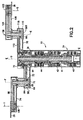
ここで図2及び3を参照すると、装置10の断面図と拡大された部分断面図とが各々示されており、駆動セクション30は垂直駆動部(図示せず)及び回転駆動部34を有している。垂直駆動部は装置10を垂直軸Z(図1参照)に沿って上げ下げすることが可能である。任意の好適なタイプの垂直移動システムを使用しても良い。好適な例が米国特許第5,894,760号に開示されており、これは本願の開示に組み入れられる。代替実施例においては、搬送装置の駆動セクションは垂直駆動部を有していなくても良い。図2及び3に示す実施例においては、回転駆動部34は上方アーム66及び前方アーム74、106の各々を独立して移動せしめるモータを有している。代替実施例においては、回転駆動部はより多くのモータを有しても良いし若しくはより少ないモータを有していても良い。本実施例においては、回転駆動部34はショルダすなわちベース結合部35に位置しており、ここにおいて上方アーム66は駆動セクションの支持構造体ケーシングに回動自在に結合されている。代替実施例においては、回転駆動部は任意の他の好適な位置に設置されても良い。回転駆動部34は一般に駆動軸アセンブリ41及び3つのモータ42、44、46を有している。代替実施例においては、該駆動部は3つより多いモータを有しても良い。駆動軸アセンブリ41は3つの駆動軸50a、50b、50cを有している。代替実施例においては3つより多い駆動軸を備えていても良い。第1モータ42はステータ48a及び中間軸50aに結合したロータ60aを有している。第2モータ44はステータ48b及び外側軸50bに結合したロータ60bを有している。第3モータ46はステータ48c及び内側軸50cに結合したロータ60cを有している。3つのステータ48a、48b、48cは、異なる高さにおいて、すなわち管部に沿って管部52に定着している。本実施例においては、第1ステータ48aは中間ステータであり、第2ステータ48bは頂部ステータであり、第3ステータ48cは底部ステータである。各ステータは一般に電磁石コイルを有している。3つの軸50a、50b、及び50cは、当該装置のショルダ結合部35において共通回転軸Dの回りに同軸状に配置されている。3つのロータ60a、60b、60cは永久磁石からなっていても良いが、代替案として永久磁石を有していない磁気誘導型ロータからなっても良い。 スリーブ62がロータ60とステータ48との間に位置しても良く、よってロボット24を真空環境で使用することが可能となり、このとき駆動軸アセンブリ41は真空環境内に位置しステータ48は真空環境の外側に位置する。しかしながら、もしロボット24が大気圧の環境のみで使用されることが企図されるときはスリーブ62を設ける必要はない。
Referring now to FIGS. 2 and 3, a cross-sectional view and an enlarged partial cross-sectional view of the
第3軸50cは内側軸であり、底部ステータ48cから延在している。内側軸は底部ステータ48cに並んだ第3ロータ60cを有している。中間軸50aは中間ステータ48aから上方に延在している。中間軸は第1ステータ48aに並んだ第1ロータ60aを有している。外側軸50bは頂部ステータ48bから上方に延在している。外側軸は上方ステータ48bに並んだ第2ロータ60bを有している。種々のベアリングが軸50及び管部52の回りに配置されており、よって各々の軸は互いに独立して且つ管部52に対して回転自在となる。本実施例においては、各軸50には位置センサ64が設けられている。位置センサ64はコントローラ11(図1参照)に、軸50の互いの回転位置及び/又は管部52に対する回転位置の信号を送るために使用される。光学式または誘導式等の任意の好適なセンサが使用可能である。
The
図2及び3を参照すると、アームアセンブリ36は、上述したように、上方アーム66及び2つの前方アーム74、106を一般に備え、前方アーム74、106は各々基板Sを保持して搬送する対応するエンドエフェクタ38、39を具備している。また上述したように、上方アーム66はショルダ結合部35において、回転駆動部のフレームに回動自在に搭載されており、よって以下にさらに理解できるようにアーム66はショルダにおいて共通回転軸Dの回りに回動自在となる。アームの対向する端部において、各々前方アーム74、106が上方アーム66に回動自在に搭載されている。従って、前方アーム74は上方アームに関してエルボ結合部回転軸Fの回りに回動自在であり、前方アーム106は対向するエルボ結合部において上方アームに関して回転軸Eの回りに回動自在である。図2から判るように、アームアセンブリ36は更に、回転駆動部34の駆動を前方アーム74、108に結合し、エンドエフェクタ38、39を上方アーム66に結合する数多くの伝達機構を有している。
Referring to FIGS. 2 and 3, the
図2において最も良くわかるように、上方アーム66は、本実施例においては一般に2つの対向するアームセクション72、78を有している。セクション72、78は、本実施例においてはアームアセンブリのショルダ結合部35において、互いに結合している。セクション72、78は互いに係止されることが可能であり、よって上方アーム66はショルダ回転軸Oの回りに一ユニットとして回転することが可能となる。対向するセクション72、78は、あるいは非係止状態であっても良く、これによって対向する両セクションの位置が互いに再配置される。代替実施例においては、上方アームは任意の所望の数のセクションからなっても良い。または係止可能なフレキシブルな結合部を伴った一体物(one piece)であっても良く、これによってセクションにおける異なる部品を互いに位置決めのために調整することが可能となる。本実施例においては、上方アームセクション72、78は互いに略同様であり、従って以下においては異なる場合を除いてセクション72を特に参照しながら説明する。上方アームセクション72は、前方アーム74を対応する回転駆動部に結合せしめる伝達部84を収納可能な中空フレームすなわちケーシングを一般に有している(伝達部116はアームセクション79内の前方アーム106に接続している)。上方アームセクション72の一端部66Lがアームアセンブリ34のエルボ結合部を画定する。柱部80がアームセクション72のフレームに端部において固定されており、その回りに伝達部84の遊び部材(例えばプーリ)84Iが回転自在に取り付けられ(同様に伝達部116の遊び部材116Iが対向するアームセクション78内において柱部80Lに取り付けられている)、よって前方アーム74に動力手段を提供する。本実施例においては、上方アームセクション72は回転駆動部34の外側軸50bに固着されている(図3参照)。対向する上方アームセクション78もまた外側軸50bに固定されているが、本実施例においては、上方アームセクション72への調整可能な結合部すなわちカップリングによって、セクション78は調整自在に外側軸50bに固定されている。図3から判るように、上方アームセクション72は、回転駆動部の外側軸50bに直接固着されている搭載面72Mを有している(本実施例においては留め具が示されているが、係合はいかなる好適なトルク移転システムでも良い)。上方アームセクション72は搭載セクション72Sをも有しており、以下に詳細に説明するように、そこに対向する上方アームセクション78が調整自在に付着される。
As best seen in FIG. 2, the
図2及び3から判るように、本実施例においては上方アームアセンブリ66の対向するセクション72、78は垂直方向にオフセットしている。代替実施例においては、調整自在に位置決め可能なセクションが、実質的に同一の垂直レベルとなるなどの互いに任意の所望の構成によって位置決めされても良い。本実施例の主セクション72の搭載すなわちカップリングセクション72Sはアームセクションのフレーム73によって形成される。本実施例のフレーム73は、駆動セクションの同軸の軸アセンブリの回りに延在し、よって対向するアームセクション78の座面73Sを形成する。本実施例においてはアームセクション72の上面と略同一面である座面73Sは、アームセクション72上においてアームセクション78の垂直及び水平位置決めの両方を担う位置決め特徴部73Hを有している。対向するアームセクション78は、搭載セクション72Sに対して略共形に構成されている係合セクション110Sを備えたフレーム110を有し、よって係合セクション110Sは搭載セクション72Sの上に搭載される。本実施例においては、位置決め特徴部73Hは座面73Sに形成された固定用孔部である。同様に、対向する上方アームセクション78の係合セクション110Sの座面も固定用孔部110Hを有している。以下に説明するように、座面に各々形成されている固定用孔部は分布されて間隔があけられており、よってアームセクション72、78を互いに指標付け(index)すべく所望の指標位置を提供する。押さえねじ、ボルト、位置決めピンなどの留め具75が、上方アームセクション78の孔部110Hを経て上方アームセクション72の係合孔部73H内に挿入され、よって上方アームの2つのアームセクション72、78を互いに係止する。留め具が移動の際のトルク移転用として十分であれば、上方アームセクション78(これは既述したものでは、回転駆動部34の外側軸50bには直接搭載されていない)は、アームセクション72がアームアセンブリのショルダ結合部において外側軸50bによって共通回転軸Dの回りを回転する際、対向するアームセクション72と一致して回転する。代替実施例においては、 対向する両アームセクションの間の位置決め及びトルク移転用に、スプラインや鍵/鍵穴などの任意の他の好適な実施可能な特徴部を使用しても良い。
As can be seen from FIGS. 2 and 3, in this embodiment, the opposing
位置決め孔部73H、110Hは、上方アームセクション72、78の各フレーム73、110上の周辺部に均等に分配されている。上方アームセクション72、78の間に所望の付加的な調整間隔を提供すべく任意の所望の数の孔部を使用しても良い。これに関しては以下に説明される。アームセクションの搭載セクション73S、110S内の位置決め孔部の数は異なっても良く、例えばセクション73S、110Sは機械的負荷用の最小数の孔部のみを含み、一方係合セクションは所望の位置調整すなわち指標用の付加的な孔部を含んでも良い。例えば、もし4つの留め具75を機械的取り付け用に使用した場合は、一搭載セクション73S、110Sは4つの搭載孔部73H、110Hを有し、他の搭載セクションはアームセクション間の調整を行なうべく8若しくは10個または任意の所望の数の孔部を有しても良い。係合表面73S、110Sは、係止用留め具75が取り除かれたときにアームセクション同士を共に安定して保持する連動式すなわち相互の指状リップ(interdigitated lips)若しくは端部(図示せず)などの更なる係合特徴部を有しても良い。これによって、上方アームセクション72、78は、以下に説明するように、位置調整を行なうべく留め具75が取り除かれたときに自立したままとなる。該係合特徴部は好適な滑動面(図示せず)を有しても良く、よって位置調整の際に滑動面に粒状物質を生じることなく両アームセクション間の滑動が可能となる。本実施例においては、上方アームセクションの搭載セクション73S、110Sはアームアセンブリのショルダ結合部35(図2参照)に配置されるように示されている。代替実施例においては、両上方アームセクション間の調整自在な結合部は上方アームに沿った任意の他の位置に設置されていても良い。
The positioning holes 73H and 110H are evenly distributed to the peripheral portions on the
図2及び3を参照すると、前方アーム74用の伝達システム84は回転駆動部34の中間軸50Aに運動可能に結合されている。前方アーム106用の伝達システム116は、例えば図3に示すように内側軸50Cに運動可能に結合されている。前方アーム伝達システム84、116概ね類似しており、本実施例においては例示目的としてベルト及びプーリシステムで示されている。代替実施例においては、前方アームを駆動部に連結する伝達部は、クランク及び連結リンクシステムやギア及びネジタイプ伝達部などの任意の他の好適な伝達部であっても良い。本実施例においては、伝達システム84、116は一般に駆動プーリ70A、70Bからなる(中央駆動軸50A、及び内側50C駆動軸に各々固定されている)。 遊びプーリ84I、116Iが上方アーム66のエルボ内の柱部80に回転自在に搭載されており、好適なベルトによって駆動プーリに結合されている。好適なベアリングを伴って柱部80の回りを自在に回転すべく搭載されている前方アーム74、106のフレームは、対応する遊びプーリに固着されている。従って、軸50aの回転は前方アーム74の回転軸Fの回りの回転を生じ、軸50Cの回転は前方アーム106の軸Eの回りの回転を生じる。伝達システム84、116は任意の所望の減速比を有しても良く、図2に示される実施例は例示目的として1:2減速比を有している。図2に示されているように、本実施例の各前方アーム74、106は、各エンドエフェクタ38、39の位置を上方アーム66に対して同期させる同期システム98、124を包含している。実施例においては、同期システム98、124は例示目的としてベルト及びプーリシステムであるが、任意の好適な同期システムを使用しても良い。図2に示すように、同期システムは上方アームの対向する両セクションの上方アーム73、110のエルボにおける柱部80(上述の如く各々のフレームに固定されている)上に固定されたベースプーリを含んでいる。遊びプーリはエンドエフェクタに固定されており、且つ前方アームに回転自在に支持されており、よってエンドエフェクタは前方アームに対して対応する回転軸G、H(アームアセンブリの腕結合部における回転軸)の回りに自在に回転する。同期装置の減速比が例示目的として2:1で示されているが、任意の好適な減速比を使用しても良い。図1において最も良くわかるように、前方アーム106及びそこに搭載されているエンドエフェクタ39は、上方アーム66から十分に離れて設置されており、よって両方のエンドエフェクタが基板Sを搬送する際に、前方アーム74がそこに搭載されているエンドエフェクタ38と共に前方アーム106を通り過ぎて自在に移動することが可能となる(図1参照)。
2 and 3, the transmission system 84 for the
装置10は異なる長さのエンドエフェクタを有してもよく、これにより装置の到達距離を所望の通り調整することが可能となる。図4乃至6は、異なる長さのエンドエフェクタ38、38A、38B、39、39A、39Bを備えた装置10のアームアセンブリ36、36A、36Bを各々示す平面図である。これらから判るように、異なる奥行きに対応するように、特に、基板の拾い上げ/放出位置に対向するように装置の到達距離が増加若しくは減少せしめられている。ここでかかる位置は搬送チャンバP(図1参照)との流通がなされる種々の処理または保持モジュール(図示せず)に存在し得る。例えば、より長いモジュールがチャンバPに結合されている場合は、エンドエフェクタは基板を設置したり拾い上げたりすべく(開口部を介して)チャンバのより遠い外側に到達しなければならない。反対に、チャンバにより短い長さのモジュールが結合している場合は、装置10は基板をそこから拾い上げたり設置したりするためにより短い到達範囲を有しても良い。装置10が所望の到達距離を有するようにする効率的な方法は、所望の到達距離に対応する長さのエンドエフェクタを使用することである。従ってより長い到達距離のときは、アームアセンブリ36はより長いエンドエフェクタを有し、より短い到達距離のときは、アームアセンブリはより短いエンドエフェクタを有する。図4に示す装置のアームアセンブリ36は、図5乃至6に対応して示されているエンドエフェクタ38A、39A及び38B、39B(これらは次第に短くなっている)に比べて長いエンドエフェクタ38、39を有している(すなわちLはL1よりも大きく、L1はL2よりも大きい)。
The
従来の搬送装置においては、より長いエンドエフェクタを有することによって結果的に総到達範囲が増大することが知られていた。更に、処理ツールの移送チャンバPは、特定の移送チャンバPと流通するモジュールのタイプ及びサイズに関する選択がなされるずっと前に製作されることが知られていた。従って、従来のシステムの移送チャンバPは搬送装置の想定される最大の到達範囲が収まるようにサイジングされている(すなわち考え得る最も長いエンドエフェクタを備えたもの)。更に、予め構築された移送チャンバ(装置の最大の到達範囲に適合するため)においては、短いエンドエフェクタを備えた従来の装置は短いエンドエフェクタの利点を得られない。なぜならば、移送チャンバ内において、装置がより長いエンドエフェクタを有しているものと想定した位置と同じ位置に従来の装置は設置されるからである。従来の装置のより短いエンドエフェクタにおいては、今度はモジュールからより遠い位置に設置されることになり、交換時間に時間がかかってしまう。 It has been known that in the conventional transfer device, the total reach is increased as a result of having a longer end effector. Further, it has been known that the transfer chamber P of the processing tool is made long before selections are made regarding the type and size of the module that is in communication with the particular transfer chamber P. Thus, the transfer chamber P of the conventional system is sized to accommodate the maximum possible reach of the transport device (ie, with the longest possible end effector). Furthermore, in pre-built transfer chambers (to fit the maximum reach of the device), conventional devices with short end effectors do not benefit from short end effectors. This is because the conventional apparatus is installed at the same position in the transfer chamber as the apparatus is supposed to have a longer end effector. The shorter end effector of the conventional device is now installed at a position farther from the module, and the replacement time takes time.
図4乃至6を参照して比較すると、本実施例のアームアセンブリ36は異なる長さのエンドエフェクタ38、38A、38B、39、39A、39Bを有しているので、最も長い所望の到達距離において搬送装置の到達距離に独立した最小の揺動時間を維持しつつ装置の到達範囲を最小化することが可能になる。更に、装置10は伸張の割合に対して最適な到達範囲を提供する。装置10、10A、10Bの総到達範囲(各々、異なる長さのエンドエフェクタ28、39、38A、39A、38B、39Bを有している)が図4乃至6に周方向の境界線Cによって特定されている。装置10、10A、10Bの到達範囲の境界線を画定すべく、図示されているアームアセンブリにおける共通回転軸Dは実質的に中心点に配置されており、到達範囲の境界線が中心からの最小半径に確立され、装置10、10A、10B及びその上に搬送される基板Sの全点をちょうど包含する境界線が提供される。図4乃至6からわかるように、装置10(図4乃至4Aに示す)は最も長いエンドエフェクタ38、39を有し(エンドエフェクタの長さLが例示目的でピボット中心及び腕結合部からエンドエフェクタ上に設置されたときの基板の中心までに延在する長さとして定義されている)、従って最も長い到達距離を有している。考えられる最小の到達範囲の境界線Cが最も長い所望の到達距離を有し、その上に基板Sを伴った装置10を包含すべく確立される。図4乃至6からわかるように、到達範囲の境界線Cは全ての装置10、10A、10Bにおいて同じサイズである。従って、図6に示す最も短い長さ(L2)のエンドエフェクタ38B、39Bを有する装置10Bの到達範囲の境界線Cは、図4に示す最も長い長さ(L)のエンドエフェクタ38、39を有する装置10の最小到達範囲Cと同じサイズである。図4乃至6に示されている装置10、10A、10Bの各々のアームアセンブリ36、36A、36Bはアームアセンブリの登録すなわち初期位置に配置されていることに留意すべきである。初期位置とは、基板の移送の際に、そこからアームアセンブリが伸張される位置であって、且つそこにアームアセンブリが引き戻される位置である。本実施例においては、アームアセンブリの初期位置は例示目的として、上方アーム66の対向する両セクション72、78、(更に図6の72A、78A及び図6の72B、78B)、及び両前方アーム74、106(更に74A、106A及び74B、106B)の両方がエンドエフェクタの運動放射軸Rに対して対称となる位置と定義する。代替実施例においては初期位置に任意の他の位置を選択しても良い。図4乃至6から判るように、登録位置のアームアセンブリにおいて、エンドエフェクタ38、39、38A、39A、39A、39Bによって保持されている基板の端部が長さに関わらず装置の到達範囲の境界線Cに存在するように、各装置のエンドエフェクタ38、39、38A、39A、38B、39Bはいずれにせよ位置されなければならない。従って、装置によって保持される基板Sの登録位置(すなわちアームアセンブリ36が登録位置のときの基板Sの位置)はエンドエフェクタの長さから独立している。
Compared with reference to FIGS. 4 to 6, the
図4乃至6に示されているように、実質的に、装置10のアームアセンブリ36は基板の登録位置と、装置の到達範囲C及びエンドエフェクタの長さとの間の関係を切り離す。従って、最大の所望のエンドエフェクタ長さ用に最小到達範囲が装置10に提供され、基板Sの登録位置、及び基板を保持していないときのエンドエフェクタの登録位置は、エンドエフェクタ長さに独立して最適に選択される。言い換えると、実施例による装置10のこれらの特徴は、作業ステーションの設計及び機能に対して直接的な利点を有しており、これは従来の搬送装置では提供することが不可能であった。例えば、想定される最も長いエンドエフェクタ長さに対応する装置10の最小到達範囲に対応するように移送チャンバPを構成することが可能である。更に、エンドエフェクタの最適位置は、その長さにかかわらず、アームアセンブリが登録位置のとき(すなわち、その上の基板Sが境界線Cに接触するようにエンドエフェクタを維持する)、エンドエフェクタの登録位置若しくはその上の基板とエンドエフェクタの伸張位置との間の望ましくない空間を効果的に閉じ、よって従来の装置のように短い長さのエンドエフェクタが移動距離の不利益を被るのが避けられる。従って、最小の装置到達範囲で最小の交換時間が常に達成される。
As shown in FIGS. 4-6, in effect, the
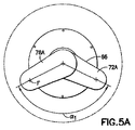
装置到達範囲の調整、及びエンドエフェクタの最適な位置決めが、調整自在な上方アーム66の対向する両セクション72、73の相対角度位置を調整することによって図4A、5A及び6Aに示すように達成される。図4A、5A及び6Aは各々前の図4乃至6のアセンブリに示された、異なる長さのエンドエフェクタ38及び39、38A及び39A、38B及び9Bに対応する3つの異なる位置における上方アームのセクション72及び78、72A及び78A、72B及び78Bを示している。従って、図4Aにおいて上方アームセクション72、78は包括角度αを形成すべく位置決めされ、図5Aにおいてアームセクション72A、79Aは包括角度α1を形成し、図6Aにおいてアームセクション72B、78Bは包括角度α2を形成する。角度α2は角度α1よりも広く、角度α1は次に角度αよりもより広い。従って、図4乃至6及び4A乃至6Aからわかるように、両上方アームセクションの間の包括角度のサイズはエンドエフェクタ38Bと39B、38Aと39A、38と39の長さ(L、L、L2)が増加するにつれて減少する。対向する両上方アームセクションの間の包括角度が減少するにつれて、アームアセンブリが登録位置のときは、アームセクションは更に後方に回転する(伸張の方向とは反対)。これは次に登録の際に前方アーム74B及び104B、74A及び104A、74及び104を後方に移動せしめ、よってエンドエフェクタを後方に移動せしめてより長いエンドエフェクタが装置の最小到達範囲内にとどまるのを可能にする。アームアセンブリの対向するセクション72、78を移動するためには、両アームセクションを一緒に係止するボルト75(図3参照)、(若しくは他の係止するデバイス)が解放される。これによって1つ若しくは両方のアームセクション72、78は、両アームセクション間での所望の包括角度α、α1、α2が達成されるまで回転軸Dの回りに互いに枢動することが可能となる。係止ボルト75はその後再導入され、よって新たな位置で再び両アームセクションを互いに係止する。上方アーム66を位置決めした後、これは次に前方アーム及び上方アームによって運搬されるエンドエフェクタを再位置決めし、コントローラ11はプログラムされて駆動モータ42、44、46の登録位置をセットする(図2参照)。その後、搬送装置10の移送運動の教示(teaching)/プログラミングが、以下に記載する以外は従来の方法によって行なうことが可能となる。
Adjustment of the device reach and optimal positioning of the end effector is achieved as shown in FIGS. 4A, 5A and 6A by adjusting the relative angular position of the opposing
アームアセンブリ36の伸張及び収縮は例えば以下の方法によって行なうことが可能である。エンドエフェクタ39を伸張するためには、上方アーム66を軸Dの回りにモータ44によって時計回りに回転させる(外側軸50Bを駆動する)。エンドエフェクタ39を支持する前方アーム106は、内側軸50C及び伝達部116を駆動するモータ46によって軸Eの回りに反時計回りに回転させる。上方アームに固定されている同期装置124は、エンドエフェクタが上方アームによって前進せしめられる際に、エンドエフェクタ39が動作放射軸Rに直線状に並ぶのを維持する。搬送操作の際、1つのエンドエフェクタが伸張されているときは、他のエンドエフェクタ38、39は収縮状態が維持されているのが望ましい。従って、例えば、エンドエフェクタ39が伸張されているときは、エンドエフェクタ38は収縮される。エンドエフェクタ38を収縮するためには、エンドエフェクタ39が伸張されているときは、前方アーム74もまた中間軸50A及び伝達部84を駆動する駆動モータ42によって軸Fの回りに反時計回りに回転せしめる。モータ42は枢動する上方アーム66に対して前方アーム74を移動せしめ、よって図4乃至6に示されるように前方アーム74の収縮位置を維持する。エンドエフェクタ38を上方アームに固定する同期装置98はエンドエフェクタ38が伸張/収縮の放射軸Rに並ぶのを維持する。伸張したエンドエフェクタの収縮は伸張とは反対の方法によって行なわれる。伸張したエンドエフェクタ39の収縮の際は、エンドエフェクタ38は、反対方向の回転(例えば軸Fの回りに時計回り)によって少なくとも一時的に収縮位置に維持される。基板の交換の際などにおける、以前に収縮されたエンドエフェクタ38の伸張動作を継続するためには、上方アーム66の回転(すなわち反時計回り、以前に伸張されたエフェクタ39の収縮の開始)が登録位置を通り過ぎて維持されて、所望の位置に到達するまで前方アーム38(すなわち時計回りによって伸張する)及び39(すなわち時計回りによって収縮して反対側の前方アームの伸張の際に収縮が維持される)の回転の延期が継続する。
The
前述したように、本実施例の説明のために、前方アーム74、106及び上方アームセクション72、78が放射軸Rに関して対称に配置される場合のアームアセンブリの位置であるとしてアームアセンブリ68の登録位置が画定され、放射軸Rに沿ってエンドエフェクタ38、39が伸張/収縮される(しかしながら、上記したように登録位置は任意の他の所望の位置として選択されても良い)。図2から判るように、本実施例においては、同期装置98、124が各々エンドエフェクタ38、39を上方アームに係止することによって、所望の包括角度α、α1、α2(図4A乃至6A参照)を提供する上方アームセクション72、78の再配置は、エンドエフェクタ38、39間の角度を形成する。これは図4において仮想軸38CL及び39CLによって概略図が示されており、これは上方アームセクション72、78が図4Aに示す包括角度αを形成すべくセットされるときのエンドエフェクタ38、39の中心線の本来の方向を示している。図5A乃至6Aに示されるように、上方アームセクション72A及び78A、72B及び78Bを更に離れてセットすることによって、エンドエフェクタ38B、39の中心線が放射軸Rに向かって回転し、両エンドエフェクタ間の角度(図4参照)が減少する。アームアセンブリの交換動作の際に、両エンドエフェクタ38、39間に角度Bに対応するために、上方アームの更なる回転が実施されて伸張したエンドエフェクタを放射軸Rに合わせる。例えば、エンドエフェクタ39が伸張された場合は、上方アーム66は回転してエンドエフェクタ中心線39CLを放射軸Rに合わせる。かかる更なる動作は伸張の前若しくは伸張の際の任意の所望の時間に実施されても良い。交換の際にエンドエフェクタ39を収縮する場合は、上方アーム66の更なる動作が行なわれてエンドエフェクタ38の中心線38CLを放射軸Rに合わせる。代替実施例においては、例えばエンドエフェクタ用の同期装置の係止を上方アームから解除する解放機構等の調整手段が設けられても良い。これによって両上方アームセクションが、エンドエフェクタが放射軸Rに関して望み通りの並びを維持しつつ望み通り位置されることが可能となる。調整の後は、係止機構は再度係合されてエンドエフェクタを上方アームに再係止する。
As described above, for purposes of describing the present embodiment, the registration of arm assembly 68 as being the position of the arm assembly when
ここで図7を参照すると、他の実施例による基板搬送装置110の断面図が示されている。本実施例における搬送装置110は上記にて説明した図1乃至6に示される装置10に全体として類似している。従って、かかる両実施例間での類似する特徴部分には同等の符号が付されており、以下に簡潔にのみ説明する。装置10と同様に、駆動セクション234及びアームアセンブリ236が存在している。アームアセンブリ236はショルダ結合部において軸Dの回りに枢動自在な少なくとも1つの上方アーム266と、上方アームの対向する両端部に枢動自在に取り付けられた2つの前方アーム274、306とを有している。上方アーム266は両セクションを互いに結合せしめる係止可能な調整自在なインターフェース273Iを備えた少なくとも2つのセクション272、278を含んでいる。インターフェース273Iは係止可能であり、よって両上方アームセクションを互いに所望の方向に保持する。非係止の際は、インターフェース273Iは上方アームセクション272、278が、上記にて説明した図4A乃至6Aに示す上方アーム66用の方法と同様の方法によって再配置されるのを可能にする。インターフェース273Iを形成する上方アームセクションの構造的な特徴は、アームセクション72、78に関して前記にて説明した特徴と類似していても良い(例えば係合表面、搭載孔部及び搭載/係止留め具)。図7に示す当該実施例の駆動セクション234は、アームアセンブリ266に取り付けられている駆動モータ242、246を有している。示されている実施例においては、駆動モータ242、246は上方アーム266に取り付けられている。駆動モータ242は前方アーム274に固着されている軸250Aに動力を供給する。軸250Aの回転は前方アーム274をアームアセンブリの1つのエルボにおける軸Fiの回りに回転せしめる。駆動モータ246は前方アーム306に固着されている軸250Cに動力を供給する。軸250Cの回転は前方アーム306をアームアセンブリの対向するエルボにおける軸Eの回りに回転せしめる。モータ244はアームアセンブリのショルダ結合部に位置している。モータ244は上方アーム266に固着されている駆動軸250Bに動力を供給し、よって上方アームをショルダにおける回転軸Dの回りに回転せしめる。同期装置298、324は前方アーム274、306の回転の際に各々エンドエフェクタ238、239を上方アームに固定する。本実施例においては前方アームモータ242、244が上方アームのフレームの外側に位置して前方アームに対応するように示されているが、代替実施例においては前方アームを駆動するモータは任意の他の所望の態様で配置されても良く、例えば上方アームのフレームや前方アームのフレームによって提供される包含材内に収納されたり、前方アームと上方アームとの間の空間に配置されたりしても良い。更に他の実施例においては、前方アーム駆動モータは上方アームのフレーム内に位置しても良いが、 駆動軸はエルボにおける前方アーム回転軸からオフセットしている。従って、この場合は例えば図2の伝達部84、116に類似の好適な伝達部は、モータ出力軸を前方アーム上の遊びプーリに駆動するように結合する。装置210のアームアセンブリ266の伸張及び収縮は装置10に関して上記において説明した方法と実質的に同様の方法によって行なわれる。本実施例においては前方アームモータ242、244は、前方アームの回転が上方アームの回転の約2倍の回転となるようにコントローラ(図1のコントローラ11と同様)によってコントロールされても良い。
Referring now to FIG. 7, a cross-sectional view of a
再度図1を参照すると、基板バッファ400が移送チャンバPに提供されても良い。バッファはチャンバ内に位置しても良く、または好適なポートを介してチャンバに流通しても良く、これによって搬送装置10(及び210)が基板をバッファ400に設置したりバッファ400から拾い上げたりすることが可能となる。バッファ400は操作の際は搬送アームの作業包絡線の外に位置している。搬送のバッファへの接近が可能となるように装置の駆動部が使用されても良い。
Referring again to FIG. 1, a
ここで図8乃至9を参照すると、他の実施例による特徴を組み入れた本発明の基板搬送装置300が示されている。図8は伸張位置にある装置300を示し、図9はその登録位置に完全に収縮された装置を示している。本実施例の搬送装置300は全体的に上記にて説明した装置10に類似しており、類似の特徴部分には同一の符号が付されている。装置10と同様に、装置300は一般的に駆動セクション330及び移動自在なアームアセンブリ330を有している。本実施例のアームアセンブリ336は2つのエンドエフェクタ338、399を備えた大概一側面のスカラ・アーム・アレンジメントと称されるものを有している。本実施例におけるアームアセンブリは上方アーム340及び該上方アームの共通端部から下向きの2つの前方アーム342、344を有している。前方アーム342、344は、以下に説明するように上方アームの同一の端部に独立したエルボ結合部346A、346Bによって独立して結合している。装置10のアームアセンブリ360と同様なアームアセンブリ336は、ショルダ結合部335において駆動セクション330に結合されており(図8参照)、よってショルダ回転軸Z1の回りに回転し(図8の矢印によって示される方向に)、よってエンドエフェクタ338、339を基板Sの拾い上げ/設置の位置に伸張/収縮する(図8の矢印Rによって示される方向に)。本実施例においては、上方アーム340は2つの異なる効果的な上方アーム長さ340A、340Bを画定し、前方アーム342、344は、以下に更に説明するように、長さが異なっており、各々の効果的な上方アーム長さに対応している。前方アーム342、344によって各々運搬されるエンドエフェクタ338、339は実質的に同等の長さであっても良い。アームアセンブリ336は、駆動部330によって操作されても良く、よってどちらのエンドエフェクタ338、339の到達距離も実質的に同等となる。アームアセンブリ336はまた、以下に更に説明するように、より大きな揺動直径の最小到達範囲を提供するように操作可能であり、これはアームの小さな揺動直径に対応して独立してアームの到達距離を与える。
Referring now to FIGS. 8-9, there is shown a
ここで図9を参照すると、搬送装置300が、上記にて説明した図1に示す搬送チャンバPと同様の代表的な搬送直径P'に位置して示されている。搬送チャンバP'は大気圧チャンバであっても良く、ここにおいてはチャンバ内部の環境は一般的に外部環境と流通する。若しくは隔離可能なチャンバであっても良く、これは内部空間を外部環境から隔離することが可能か若しくは隔離しなければならない。例えば、隔離チャンバP'は不活性ガス環境を有するか、若しくはチャンバの内部は真空が維持されていても良い。搬送装置300はチャンバPの装置10(図1参照)と実質的に同じ要領でチャンバP'内に取り付けられるか又は別の方法で配置されても良い。
Referring now to FIG. 9, the
更にここで図10を参照すると、搬送装置の断面図が示されており、駆動セクション334は同軸の軸アセンブリ360を収納する外部ハウジング334H及び3つのモータ362、364、366を有しても良い。代替実施例においては、駆動セクションは3つのモータより多いことも少ないこともある。駆動軸アセンブリ360は3つの駆動軸368a、368b、及び368cを有している。代替実施例においては3つの駆動軸より多いことも少ないこともある。第1モータ362はステータ378aと内側軸368aに結合されたロータ380aとを有している。第2モータ364はステータ378bと中間軸368bに結合されたロータ380bとを有している。第3モータ366はステータ 378cと外側軸368cに結合されたロータ 380cとを有している。3つのステータ378a、378b、378cはハウジング334Hの異なる垂直高さ若しくはハウジングに沿った位置に固着されている。本実施例においては第1ステータ378aは底部ステータであり、第2ステータ378bは中間ステータであり、第3ステータ378cは頂部ステータである。各ステータは一般的に電磁石コイルを有している。3つの軸368a、368b、及び368cは同軸であってショルダ回転軸Zに同軸として配置されている。3つのロータ380a、380b、380cは永久磁石からなっても良いが、代替案として永久磁石を有しない磁気誘導型ロータからなっても良い。スリーブ363はロータ380とステータ378との間に位置し、よって駆動軸アセンブリ360が真空環境内に設置されてステータ378は真空環境の外側に設置される状態で、搬送装置300が真空環境内で使用可能となる。しかしながら、大気圧環境下での使用のみが企図されている場合は、スリーブ363は必要ではない(図参照)。
Still referring to FIG. 10, a cross-sectional view of the transport apparatus is shown, wherein the
第1軸368aは内側軸であって底部ステータ378aから延在している。内側軸は底部ステータ378aに並んだ第1ロータ380aを有している。中間軸368bは中間ステータ378bから上方に延在している。中間軸は第2ステータ378bに並んだ第2ロータ380bを有している。外側軸368cは頂部ステータ378cから上方に延在している。外側軸は上方ステータ378cに並んだ第3ロータ380cを有している。種々のベアリングが軸368及びハウジング334Hの周りに配置されており、よって各軸が互いに独立して且つハウジング334Hから独立して回転自在になるのを可能にしている。各軸368は好適な位置センサを有しても良く、これによってコントローラ11(図1参照)と同様のコントローラに互いに関する及び/又はハウジング334Hに関する軸368の回転位置の信号を送る。光学や誘導等の任意の好適なセンサを使用しても良い。
The
図10からわかるように、上方アーム340は好適なベアリングを使用して上方アームがショルダ回転軸Zの回りに回転することが可能となっており、駆動セクション334のケーシング334H上に配置されている。上方アーム340は駆動伝達部320、310及びエンドエフェクタを好適な電源(図示せず)及びコントローラ11(図1参照)に結合する通信回線(図示せず)を収納可能な中空フレーム若しくはケーシングを有しても良い。上方アームのフレーム340Fは所望の単一構造の構成要素若しくはアセンブリであっても良い。図10に示されるように、上方アームフレームは一端部340Rが外側軸308Cに固定して結合されており、よって軸及び上方アーム340はスカラアーム336のショルダ結合部335において回転軸Zの回りに一体として回転する。本実施例においては、上方アーム340は2つの独立した軸アセンブリ375A、375Bを支持する。軸アセンブリ375A、375Bは上方アームフレームのショルダ端部340Rに対向する端部340Fに位置している。軸アセンブリ375A、375Bは、各前方アーム342、344を上方アーム340に独立して取り付ける各々独立したエルボ結合部346A、346Bを画定する。軸アセンブリ375Aは一般的に回転自在な外側軸374からなり、これはエルボ結合部346Aにおいて回転軸Zの回りに自在に回転すべく好適なベアリングに安定的に保持されている。軸アセンブリ375Aは更に内側柱部373を有しても良く、これは全体的に軸374と同心であるが、図10に示すように上方アームフレームに固定されている。エルボ結合部346Bの軸アセンブリ375Bは、実質的にアセンブリ375Aと同様であり、外側回転軸372及び同心内側柱部373Bは上方アームフレームに固定されている。エルボ結合部346Bの回転自在な軸372は回転軸Z1"の回りに回転自在である。
As can be seen from FIG. 10, the
図8において最も良くわかるように、軸アセンブリ375A、375Bは半径及び角度オフセットを有して上方アーム340上に配置されている。本実施例においては、軸アセンブリ375A'(エルボ346A用)はエルボアセンブリ346B用の軸アセンブリ375Bよりもショルダ結合部の中心(回転軸Z'によって画定される)に半径方向により近く配置されている。従って、エルボ結合部346Aの回転中心(回転軸Z1'によって画定される)と上方アームの回転中心(すなわち回転軸Z')との間の半径方向の長さ340Aは第2エルボ結合部346Bの回転中心(回転軸Z1''によって画定される)と上方アームの回転中心との間の対応する半径長さ340Bよりも小さい。軸アセンブリ375A、375は更に図示される角度オフセットBによって分けられている。図8から判るように、軸アセンブリ 375A、375Bは両方とも移動軸Tの一側部に配置されている(腕結合部回転中心Z2'、Z3'とショルダ結合部回転中心Z'とを結合し、それに沿ってRの方向にエンドエフェクタが移動せしめられる)。移動軸Tに最も近い軸アセンブリ375A(若しくはエルボ結合部346A)は、外側軸アセンブリ375B(若しくはエルボ結合部346B)の半径340Bと比較してより短い半径(長さ)340Aを有している。上方アームは従ってエンドエフェクタの移動軸Tの一側部に位置する2つの有効な上方アーム長さ(半径340A、340Bに対応する)を有していると考えられる。本実施例においては、上方アームのフレーム340Fは単一アームとして表わされるモノリシック形状として示されてきたが、代替実施例においては、上方アームフレームは2つのオフセット軸アセンブリを移動の軸の一側部において配置して支持する任意の他の好適な形状を有しても良い(例えば、上方アームのフレームは、分岐してショルダ結合部335に類似したショルダ結合部から独立したエルボ結合部に延在した2つのアームとして表わされても良い)。半径及び角度オフセットは望み通り確立されて最小装置到達範囲を提供し、最小分離を有するエルボ結合部346A、346Bが図8に示されていることが判る。
As best seen in FIG. 8, the
再度図10を参照すると、前方アーム342が軸374に固定して取り付けられており、よって軸374と一体としてエルボ結合部346Aにおける回転軸Z1'の回りに回転する。第2前方アーム344は軸372に固定して取り付けられており、よって軸372と一体としてエルボ結合部346Bにおける回転軸Z1''の回りに回転する。図8から判るように、前方アーム342、344は各々異なる有効長さを有している(有効前方アーム長さはここにおいて、エルボ結合部346B、346Aにおける回転中心Z1'、Z1''と前方アーム342、344に対応する腕結合部338W、339Wにおける回転中心Z'3、Z'2との間の距離と定義される)。本実施例においては、前方アーム342は前方アーム344よりも短い。図8から判るように、各前方アーム342、344の有効長さは、所定の前方アームを上方アーム340に結合する対応するエルボ結合部346A、346Bへの半径長さ340A、340Bに整合している。従って、本実施例においてはエルボ結合部346Aにおける前方アーム342の有効長さは実質的に半径長さ340Aに等しい。同様に、エルボ結合部346Bにおける前方アーム344は半径長さ340Bに実質的に等しい長さを有している。一方の前方アーム344は他方から垂直方向にねじれており、よって両方のアームが各々の回転軸Z1'、Z1''の回りに互いに干渉することなく自在に枢動されることが可能となる。本実施例においては、外側のより長い前方アーム344が内側のより短い前方アーム342よりも上側に設置されている。軸アセンブリ375Bにおいては十分な離間状態が確保されており、よって上方アーム344にはより低いアーム342に関して十分な間隔が設けられている。
Referring to FIG. 10 again, the
図8を参照すると、各前方アーム342、344は対応する回転軸Z3'、Z2'の回りにそれを支持する前方アームに関して回転することが可能なエンドエフェクタ338、339を搭載している。本実施例においては、エンドエフェクタ338、339は同等の有効長さを有しているが、代替実施例においては、異なる長さのエンドエフェクタを使用しても良い。他の代替実施例においては1以上のエンドエフェクタはバッチ式の保持能力を有しても良い(例えば多数の基板保持列を有することによる)。本実施例においては、エンドエフェクタ338、339を各々備えた搬送能力は実質的に同等である。各前方アーム342、344の回転は駆動セクション334の対応する駆動軸368A、368Bから独立して動力を得ている。
Referring to FIG. 8, each
図10から判るように、本実施例においては、中間軸368bは上方アーム340の伝達部320に結合され、内側軸368aは上方アームの伝達部210に結合されている。第1伝達部320は本実施例においては駆動プーリ322、遊びプーリ324及び駆動ケーブルすなわちベルト326を有しても良い。代替実施例においては、任意の好適な伝達部を使用しても良い。駆動プーリ322は中間軸368bの頂部に固定して取り付けられており、遊びプーリ324に駆動ベルト326によって結合されている。遊びプーリ324は前方アームを上方アームに結合する軸アセンブリ375Bの軸372に固定して取り付けられている。上方アームリンク340の第2伝達部310は駆動プーリ312、遊びプーリ314、及び駆動ベルト若しくはケーブル316を有しても良い。駆動プーリ312は駆動セクション334内の同軸の軸アセンブリ360の内側軸368aの頂部に固定して取り付けられている。遊びプーリ314は前方アーム342を上方アーム340に結合する軸アセンブリ375Aの軸374に固定して取り付けられている。駆動ベルト316は駆動プーリ312を遊びプーリ314に結合する。第2伝達部310の遊びプーリと駆動プーリ314、312との間の減速比、及び第1伝達部320の遊びプーリと駆動プーリ324、322との間の減速比は、本実施例においては約1:2であるが、代替実施例においては遊びプーリと駆動プーリとの間の減速比は所望のものでも良い。駆動ベルト316、326は各々の遊びプーリ314、304を対応する駆動プーリ312、322と同一方向に回転するように構成されている(例えば駆動プーリ320、322の時計回りの回転は遊びプーリ314、322の時計回りの回転を生じる)。
As can be seen from FIG. 10, in this embodiment, the
図10に示すように、エンドエフェクタ338、339の対応する回転軸Z3'、Z2'の回りの回転は同期装置396、408によって上方アーム340に追従せしめられる。
As shown in FIG. 10, the rotation of the
前方アーム同期装置396は前方アーム342内に位置しても良く、ドラム402、遊びプーリ404、及び結合ケーブル若しくはベルト406を有しても良い。ドラム402は静止柱部373Aに固定して取り付けられている(上方アーム340に固定される)。 遊びプーリ404はエンドエフェクタ338'を前方アーム342に枢動自在に結合している軸398に固定して取り付けられている。ベルト406はドラム402を遊び404に結合しており、好適には全体として環形状を有しており(図示せず)、よって前方アームリンク342の軸Zl'の回りの回転は遊び404の軸Z3'の回りの逆回転を生じる。固定柱部373A上のドラム402の直径の遊びプーリ404に対する直径比は約1:2である。上記した前方アーム同期装置396及び第2伝達部310の比(図10参照)はエンドエフェクタ338が軸Tに沿って実質的に直線状の動作を維持することをもたらす(図8参照)。前方アーム同期機構408は前方アーム344内に位置し、ドラム 410、 遊び 412、及び結合ケーブル若しくはベルト414からなる。駆動部410は固定柱部373Bの頂部に固定して取り付けられている。遊び412はエンドエフェクタ339を前方アームリンク344に枢動自在に結合する軸416に固定して取り付けられている。ケーブル414はドラム410を遊び412に結合し、好適には全体的に環形状に形成されており(図示せず)、よって前方アームリンク344の軸Zi''回りの回転は遊び412に軸Z2'回りに逆回転を生じる。遊び412と同期装置408のドラム410との間の直径比は約2:1である。これらの比は上方アーム340の第1伝達部320の減速比と組み合わせて、スカラアーム236が伸張若しくは収縮したときに、エンドエフェクタ339の実質的に直線状に横断軸Tに沿った横断を生じる。
The
図10からわかるように、本実施例においてはエンドエフェクタ338、339は各々前方アームの上面に隣接した対応する前方アーム342、344に取り付けられている。これによって両前方アームが搬送チャンバPの真空スロット弁(図示せず)を通って通過することが可能となる(図8参照)。代替実施例においては、両エンドエフェクタは各々の前方アームに取り付けられても良く、よって図1乃至2に示されるエンドエフェクタ38、39と同様の要領によって上方の前方アームと下方の前方アームとの間に位置する。図10Aは、更に他の実施例による構成によって前方アームに取り付けられているエンドエフェクタを示している。エンドエフェクタ338'、339'及び前方アーム342'、344'は、本実施例においては、記載する以外は上記にて説明した図8乃至10に示す装置300のエンドエフェクタ及び前方アームと実質的に同様であり、同様の特徴部分には同一の符号を付している。エンドエフェクタ338'、339'は、図10Aに示すように、対応する前方アーム342'、344'の底部に取り付けられている。エンドエフェクタ339'は図示する伸張部分339'E を有しても良く、よってエンドエフェクタ339'の水平ブレード339'B(上方前方アーム344'によって運搬される)がエンドエフェクタ338'(下方の前方アーム342'によって運搬される)に垂直方向に近接して位置にすることが可能となる。図8及び10Aから判るように、前方アーム342、3444、342'、344'の異なる長さは、本実施例においては、交換動作の際にエンドエフェクタ及び前方アームが互いに通過して移動することを可能にすべく従来のブリッジの上にエンドエフェクタの1つを取り付けることなく、装置300が第1交換動作を行なうことが可能となる。本実施例においては、異なる長さの前方アーム342、344、342'、344'及び前方アームが各々回転するエルボ結合部346A、346Bのオフセットは、以下に説明するように、前方アーム及び対応するエンドエフェクタ338、339、338'、339が交換動作の際に互いに他を通過して自在に移動することが可能となるのに十分である。
As can be seen from FIG. 10, in this embodiment, the
アームアセンブリ336の伸張及び収縮は図1乃至2に示すアームアセンブリ36に関して説明した方法と同様の方法によって達成せしめられても良い。エンドエフェクタ338と伸張するために(例えば図9に示すその登録位置から)、上方アーム340は軸Z'の回りに時計回りに回転する(図10の駆動軸368Cによって)。エンドエフェクタ338を保持する前方アーム342は軸Z1'の回りに反時計回りに回転し(駆動軸368Aによって)、同期装置396はエンドエフェクタ338 が移動の軸Tに正確に並ぶことを維持する(図8参照)。第2前方アーム344、及び対応するエンドエフェクタ339は上方アームに関してその収縮位置を維持しても良い(図9参照)。図8を参照すると、参照339W'はエンドエフェクタ・リスト部339Wの位置を示しており、エンドエフェクタ339はその収縮位置であり、上部が移動したときはエンドエフェクタ338は収縮される。エンドエフェクタ338を収縮するためには、前方アーム342はここで軸Z1'の回りに時計回りに回転する。直線342Rはその収縮位置に向かって軸Z1'の回りに回転する際の前方アーム342の最も外側の部分の経路を示しており、このとき上方アーム340はエンドエフェクタ339を伸張する準備ができてその伸張位置を維持している。図8及び図9から判るように、エンドエフェクタ338をその収縮位置に移動させる前方アーム342は、エンドエフェクタ339のリスト部339Wを通過し、よって前方アーム及び対応するエンドエフェクタが互いに自在に通過することを可能にし、よってエンドエフェクタのブリッジを用いることなく交換動作を達成する。エンドエフェクタ339は前方アーム3434を駆動軸368Bによって反時計回り及び時計回りに軸Z1''の回りに回転することによって各々伸張及び収縮される(図10参照)。図9からわかるように、より長い前方アーム344は(短い前方アーム342に比べて)収縮そしてその後の伸張の際は回転された状態下にあり、よってエンドエフェクタ339の登録位置は装置300の到達範囲を最小化するように位置される。
Extension and contraction of the
搬送装置300は共通(同心)のエルボ結合部に取り付けられた多数の前方アームを備えた従来の搬送装置に比べて簡素化したベアリング及び通信回線貫通接続を有している。図11は搬送装置300の上方アーム340、エルボ結合部346A、346B及び前方アーム342、344を介してエンドエフェクタ338、339に各々供給されている通信回線338L、339Lのフィードアレンジメントの例を示している。図示されている当該フィードアレンジメントは両前方アーム間の真空リップシール及びスリップリングの必要性を除去する。よって結果的に磨耗部の少ないより簡易なアームとなり、これは従来のデバイスに比べてより信頼性が向上して容易に製造できる。
The
前記の記述は本発明の単なる説明用の実例であることを理解すべきである。種々の変更や改良が当業者によって本発明から逸脱することなく考え出され得る。従って、本発明はここに添付する特許請求の範囲の範囲に包含される当該全ての代替、変更、差異を包含することを企図している。 It should be understood that the foregoing description is only illustrative of the invention. Various changes and modifications can be devised by those skilled in the art without departing from the invention. Accordingly, the present invention is intended to embrace all such alternatives, modifications and variances that fall within the scope of the appended claims.
Claims (22)
駆動セクションと、
前記駆動セクションに作動自在に結合されたスカラアームと、を有し、
前記駆動セクションは前記スカラアームを作動せしめ、
前記スカラアームは、上方アームと、前記上方アームに可動自在に取り付けられてその上に基板を保持することが可能な少なくとも1つの前方アームと、を有し、
前記上方アームは、第1及び第2のアームセクションを有する共通アームリンクであり、前記第1及び第2のアームセクションが前記第1及び第2のアームセクションを互いに対して選択された固定角度に選択的に位置決めする係止及び解放可能な結合部によって互いに結合されていることで、前記上方アームの所定の形状が変更可能であることを特徴とする装置。 A substrate transfer device,
A drive section;
A scalar arm operably coupled to the drive section;
The drive section actuates the scalar arm;
The SCARA arm has an upper arm and at least one front arm movably attached to the upper arm and capable of holding a substrate thereon,
The upper arm is a common arm link having first and second arm sections, the first and second arm sections having the first and second arm sections selected at a fixed angle relative to each other. The device is characterized in that the predetermined shape of the upper arm is changeable by being connected to each other by a selectively positioning locking and releasable connection .
駆動セクションと、
前記駆動セクションに作動自在に結合されたスカラアームと、を有し、
前記駆動セクションは前記スカラアームを作動せしめ、
前記スカラアームは、上方アームと、前記上方アームに移動自在に取り付けられてその上に基板を保持することが可能な少なくとも1つの前方アームと、を有し
前記上方アームは、剛体である第1アームセクション、及び係止及び解放可能な結合部によって前記第1アームセクションに固定及び解放自在に結合された剛体である第2アームセクションを有する共通アームリンクであり、解放時には、前記上方アームの所定の形状の変更のために前記第1アームセクションは前記第2アームセクションに対して移動自在であり、固定時には前記第1及び第2のアームセクションが互いに対して係止されることを特徴とする装置。 A substrate transfer device,
A drive section;
A scalar arm operably coupled to the drive section;
The drive section actuates the scalar arm;
The SCARA arm includes an upper arm and at least one front arm that is movably attached to the upper arm and can hold a substrate thereon. The upper arm is a rigid first body. A common arm link having an arm section and a second arm section which is a rigid body fixedly and releasably coupled to the first arm section by a locking and releasable coupling portion ; The first arm section is movable with respect to the second arm section to change the shape of the first and second arm sections, and the first and second arm sections are locked to each other when fixed. apparatus.
Applications Claiming Priority (3)
| Application Number | Priority Date | Filing Date | Title |
|---|---|---|---|
| US57857104P | 2004-06-09 | 2004-06-09 | |
| US60/578,571 | 2004-06-09 | ||
| PCT/US2005/020304 WO2005123565A2 (en) | 2004-06-09 | 2005-06-09 | Dual sacra arm |
Publications (3)
| Publication Number | Publication Date |
|---|---|
| JP2008502498A JP2008502498A (en) | 2008-01-31 |
| JP2008502498A5 JP2008502498A5 (en) | 2012-05-31 |
| JP5264171B2 true JP5264171B2 (en) | 2013-08-14 |
Family
ID=35510311
Family Applications (1)
| Application Number | Title | Priority Date | Filing Date |
|---|---|---|---|
| JP2007527725A Active JP5264171B2 (en) | 2004-06-09 | 2005-06-09 | Substrate transfer device |
Country Status (4)
| Country | Link |
|---|---|
| US (5) | US8376685B2 (en) |
| JP (1) | JP5264171B2 (en) |
| KR (1) | KR101398665B1 (en) |
| WO (1) | WO2005123565A2 (en) |
Families Citing this family (64)
| Publication number | Priority date | Publication date | Assignee | Title |
|---|---|---|---|---|
| US10086511B2 (en) | 2003-11-10 | 2018-10-02 | Brooks Automation, Inc. | Semiconductor manufacturing systems |
| US7458763B2 (en) | 2003-11-10 | 2008-12-02 | Blueshift Technologies, Inc. | Mid-entry load lock for semiconductor handling system |
| US20070269297A1 (en) | 2003-11-10 | 2007-11-22 | Meulen Peter V D | Semiconductor wafer handling and transport |
| US8376685B2 (en) * | 2004-06-09 | 2013-02-19 | Brooks Automation, Inc. | Dual scara arm |
| US7374525B2 (en) * | 2006-01-25 | 2008-05-20 | Protedyne Corporation | SCARA-type robotic system |
| US9117859B2 (en) * | 2006-08-31 | 2015-08-25 | Brooks Automation, Inc. | Compact processing apparatus |
| US8950998B2 (en) * | 2007-02-27 | 2015-02-10 | Brooks Automation, Inc. | Batch substrate handling |
| US8016542B2 (en) * | 2007-05-31 | 2011-09-13 | Applied Materials, Inc. | Methods and apparatus for extending the reach of a dual scara robot linkage |
| US8283813B2 (en) | 2007-06-27 | 2012-10-09 | Brooks Automation, Inc. | Robot drive with magnetic spindle bearings |
| US9752615B2 (en) | 2007-06-27 | 2017-09-05 | Brooks Automation, Inc. | Reduced-complexity self-bearing brushless DC motor |
| KR101496654B1 (en) | 2007-06-27 | 2015-02-27 | 브룩스 오토메이션 인코퍼레이티드 | Motor stator with lift capability and reduced cogging characteristics |
| WO2009003186A1 (en) | 2007-06-27 | 2008-12-31 | Brooks Automation, Inc. | Multiple dimension position sensor |
| US7834618B2 (en) | 2007-06-27 | 2010-11-16 | Brooks Automation, Inc. | Position sensor system |
| KR20100056468A (en) * | 2007-07-17 | 2010-05-27 | 브룩스 오토메이션 인코퍼레이티드 | Substrate processing apparatus with motors integral to chamber walls |
| WO2010080983A2 (en) | 2009-01-11 | 2010-07-15 | Applied Materials, Inc. | Robot systems, apparatus and methods for transporting substrates in electronic device manufacturing |
| JP5480562B2 (en) * | 2009-08-26 | 2014-04-23 | 日本電産サンキョー株式会社 | Industrial robot |
| US8079459B2 (en) * | 2009-11-19 | 2011-12-20 | The Unites States Of America As Represented By The Secretary Of The Army | Transport apparatus |
| CN103237634B (en) * | 2010-10-08 | 2016-12-14 | 布鲁克斯自动化公司 | The vacuum robot of Driven by Coaxial |
| WO2012064949A1 (en) * | 2010-11-10 | 2012-05-18 | Brooks Automation, Inc. | Dual arm robot |
| KR102392186B1 (en) * | 2011-03-11 | 2022-04-28 | 브룩스 오토메이션 인코퍼레이티드 | Substrate processing tool |
| US9267585B2 (en) * | 2011-06-02 | 2016-02-23 | Empire Technology Development Llc | Actuator with joints |
| CN102709221A (en) * | 2011-06-28 | 2012-10-03 | 清华大学 | Planar three degree-of-freedom wafer transmitting device |
| US9076829B2 (en) * | 2011-08-08 | 2015-07-07 | Applied Materials, Inc. | Robot systems, apparatus, and methods adapted to transport substrates in electronic device manufacturing |
| KR20230084597A (en) * | 2011-09-16 | 2023-06-13 | 퍼시몬 테크놀로지스 코포레이션 | A Transport Apparatus and A Processing Apparatus Comprising the Same |
| US9202733B2 (en) | 2011-11-07 | 2015-12-01 | Persimmon Technologies Corporation | Robot system with independent arms |
| US9401296B2 (en) | 2011-11-29 | 2016-07-26 | Persimmon Technologies Corporation | Vacuum robot adapted to grip and transport a substrate and method thereof with passive bias |
| US8961099B2 (en) * | 2012-01-13 | 2015-02-24 | Novellus Systems, Inc. | Dual arm vacuum robot with common drive pulley |
| TWI629743B (en) * | 2012-02-10 | 2018-07-11 | 布魯克斯自動機械公司 | Substrate processing apparatus |
| US9117865B2 (en) * | 2012-04-12 | 2015-08-25 | Applied Materials, Inc. | Robot systems, apparatus, and methods having independently rotatable waists |
| US10679883B2 (en) * | 2012-04-19 | 2020-06-09 | Intevac, Inc. | Wafer plate and mask arrangement for substrate fabrication |
| KR102153608B1 (en) * | 2012-07-05 | 2020-09-08 | 어플라이드 머티어리얼스, 인코포레이티드 | Boom drive apparatus, multi-arm robot apparatus, electronic device processing systems, and methods for transporting substrates in electronic device manufacturing systems |
| CN103802104B (en) * | 2012-11-08 | 2016-05-18 | 沈阳新松机器人自动化股份有限公司 | A kind of drive unit |
| US9190306B2 (en) | 2012-11-30 | 2015-11-17 | Lam Research Corporation | Dual arm vacuum robot |
| WO2014087879A1 (en) * | 2012-12-04 | 2014-06-12 | タツモ株式会社 | Link-type transportation robot |
| US11353084B2 (en) * | 2013-03-15 | 2022-06-07 | Clearmotion Acquisition I Llc | Rotary actuator driven vibration isolation |
| KR20210014778A (en) * | 2013-03-15 | 2021-02-09 | 어플라이드 머티어리얼스, 인코포레이티드 | Substrate deposition systems, robot transfer apparatus, and methods for electronic device manufacturing |
| WO2014197537A1 (en) * | 2013-06-05 | 2014-12-11 | Persimmon Technologies, Corp. | Robot and adaptive placement system and method |
| US10134621B2 (en) * | 2013-12-17 | 2018-11-20 | Brooks Automation, Inc. | Substrate transport apparatus |
| TWI657524B (en) * | 2013-12-17 | 2019-04-21 | 美商布魯克斯自動機械公司 | Substrate transport apparatus |
| US11587813B2 (en) | 2013-12-17 | 2023-02-21 | Brooks Automation Us, Llc | Substrate transport apparatus |
| JP6550391B2 (en) * | 2014-01-05 | 2019-07-24 | アプライド マテリアルズ インコーポレイテッドApplied Materials,Incorporated | Robotic apparatus, drive assembly and method for transferring a substrate in electronic device manufacturing |
| CN106463438B (en) * | 2014-01-28 | 2019-09-10 | 布鲁克斯自动化公司 | Substrate transport equipment |
| US10269606B2 (en) * | 2014-05-05 | 2019-04-23 | Persimmon Technologies Corporation | Two-link arm trajectory |
| KR101963334B1 (en) * | 2014-12-26 | 2019-03-28 | 카와사키 주코교 카부시키 카이샤 | Double-armed robot |
| JP1534869S (en) * | 2015-01-30 | 2015-10-13 | ||
| WO2016189740A1 (en) * | 2015-05-28 | 2016-12-01 | 株式会社安川電機 | Robot system, teaching jig and teaching method |
| TWI724971B (en) | 2016-06-28 | 2021-04-11 | 美商應用材料股份有限公司 | Dual robot including spaced upper arms and interleaved wrists and systems and methods including same |
| JP6747136B2 (en) * | 2016-07-22 | 2020-08-26 | 東京エレクトロン株式会社 | Substrate processing equipment |
| GB201701246D0 (en) * | 2017-01-25 | 2017-03-08 | Fives Landis Ltd | Machine tools and methods of operation thereof |
| US10651067B2 (en) * | 2017-01-26 | 2020-05-12 | Brooks Automation, Inc. | Method and apparatus for substrate transport apparatus position compensation |
| US10580682B2 (en) * | 2017-02-15 | 2020-03-03 | Persimmon Technologies, Corp. | Material-handling robot with multiple end-effectors |
| US10421196B2 (en) * | 2017-07-26 | 2019-09-24 | Daihen Corporation | Transfer apparatus |
| CN109994358B (en) * | 2017-12-29 | 2021-04-27 | 中微半导体设备(上海)股份有限公司 | Plasma processing system and operation method thereof |
| JP7183635B2 (en) * | 2018-08-31 | 2022-12-06 | 東京エレクトロン株式会社 | SUBSTRATE TRANSFER MECHANISM, SUBSTRATE PROCESSING APPARATUS AND SUBSTRATE TRANSFER METHOD |
| KR101931290B1 (en) * | 2018-09-12 | 2018-12-20 | 주식회사 싸이맥스 | Transfer Robot With 7-Axis |
| EP3672040A1 (en) * | 2018-12-17 | 2020-06-24 | Nexperia B.V. | Device for enabling a rotating and translating movement by means of a single motor; apparatus and system comprising such a device |
| JP1644507S (en) * | 2019-03-27 | 2019-10-28 | ||
| JP1650339S (en) * | 2019-03-27 | 2020-01-20 | ||
| JP1644506S (en) * | 2019-03-27 | 2019-10-28 | ||
| JP1644505S (en) * | 2019-03-27 | 2019-10-28 | ||
| US11850742B2 (en) | 2019-06-07 | 2023-12-26 | Applied Materials, Inc. | Dual robot including splayed end effectors and systems and methods including same |
| JP6880519B2 (en) * | 2019-11-11 | 2021-06-02 | 株式会社安川電機 | Robot system, robot control method, semiconductor manufacturing system |
| US11937890B2 (en) * | 2019-11-14 | 2024-03-26 | Intuitive Surgical Operations, Inc. | Direct drive for mechanical arm assembly |
| USD997223S1 (en) * | 2023-06-07 | 2023-08-29 | Primate Robot Hong Kong Co., Limited | Robot |
Family Cites Families (39)
| Publication number | Priority date | Publication date | Assignee | Title |
|---|---|---|---|---|
| US669434A (en) | 1900-08-21 | 1901-03-05 | William D Adams | Machine for splitting ears of corn. |
| US3411644A (en) | 1966-07-07 | 1968-11-19 | Duchess Corp | Boat loader and carrier |
| GB1202279A (en) * | 1966-11-18 | 1970-08-12 | Massey Ferguson Services Nv | Improvements in material handling devices which include a pivotable boom |
| US3550800A (en) | 1968-12-16 | 1970-12-29 | W E Robinson | Boat carrier and launcher for pickup trucks |
| US3734321A (en) | 1970-01-13 | 1973-05-22 | D Long | Truck load bed boat loader and carrier |
| US3648866A (en) | 1970-05-18 | 1972-03-14 | Harold M Slown | Hoist and frame for boat and trailer |
| US3732998A (en) | 1971-09-28 | 1973-05-15 | Raymond Lee Organization Inc | Boat rack |
| US3843002A (en) | 1972-07-11 | 1974-10-22 | C Pihlgren | Boat and trailer loading device |
| US3840133A (en) | 1973-05-31 | 1974-10-08 | A Berg | Boat trailer loading and supporting device |
| US3877594A (en) | 1973-11-21 | 1975-04-15 | Donald L Coakley | Car top boat carrier with loader and unloader |
| US3871540A (en) | 1973-12-12 | 1975-03-18 | Smittys Easy Tow | Device for loading and carrying boats on pickup trucks |
| US3972433A (en) | 1974-08-07 | 1976-08-03 | Reed Henry W | Self loading and carrying apparatus |
| US4212580A (en) | 1978-06-27 | 1980-07-15 | Fluck Ronald O | Boat launcher for truck bed |
| US4239438A (en) | 1978-12-04 | 1980-12-16 | Everson Clifford R | Device for lifting and carrying loads on top of pickup trucks |
| US4274788A (en) | 1980-01-17 | 1981-06-23 | Sutton Luther M | Vehicle mounted carriage and elevating apparatus |
| US4420165A (en) | 1980-11-12 | 1983-12-13 | Goodin William K | Multi-trailer assembly |
| JPH0825151B2 (en) * | 1988-09-16 | 1996-03-13 | 東京応化工業株式会社 | Handling unit |
| US4983206A (en) * | 1990-03-16 | 1991-01-08 | Frazier-Simplex, Inc. | Batch charger for glass furnace |
| US5069595A (en) | 1990-08-06 | 1991-12-03 | Smith Douglas J | Loader and carrier apparatus for boat and trailer |
| US5108248A (en) | 1991-01-09 | 1992-04-28 | Murrill Robert E | Apparatus for loading boat trailers on truck beds |
| US5123799A (en) | 1991-07-01 | 1992-06-23 | Breazeale Lloyd E | Trailer loading apparatus |
| US5513946A (en) * | 1991-08-27 | 1996-05-07 | Canon Kabushiki Kaisha | Clean robot |
| US5447408A (en) | 1992-03-05 | 1995-09-05 | Smith; Hank | Boat trailer overhead carrying device |
| US5511928A (en) | 1994-11-04 | 1996-04-30 | Ellis; Robert S. | Boat loading device |
| US5609462A (en) | 1995-06-07 | 1997-03-11 | Reimer; Arnald E. | Boat loader and carrier |
| US5765444A (en) * | 1995-07-10 | 1998-06-16 | Kensington Laboratories, Inc. | Dual end effector, multiple link robot arm system with corner reacharound and extended reach capabilities |
| JPH10163296A (en) | 1996-11-27 | 1998-06-19 | Rootsue Kk | Board carrying equipment |
| JPH10329069A (en) * | 1997-03-31 | 1998-12-15 | Daihen Corp | Control method for conveyance system |
| US6034000A (en) * | 1997-07-28 | 2000-03-07 | Applied Materials, Inc. | Multiple loadlock system |
| US6155768A (en) * | 1998-01-30 | 2000-12-05 | Kensington Laboratories, Inc. | Multiple link robot arm system implemented with offset end effectors to provide extended reach and enhanced throughput |
| JPH11284049A (en) | 1998-03-31 | 1999-10-15 | Mecs Corp | Thin-type substrate carrying robot |
| JPH11300663A (en) * | 1998-04-24 | 1999-11-02 | Mecs Corp | Thin substrate conveying device |
| US6056504A (en) * | 1998-06-05 | 2000-05-02 | Applied Materials, Inc. | Adjustable frog-leg robot |
| US5921741A (en) | 1998-08-26 | 1999-07-13 | Heimgartner; Ernie | Trailer and loading device |
| US6485250B2 (en) * | 1998-12-30 | 2002-11-26 | Brooks Automation Inc. | Substrate transport apparatus with multiple arms on a common axis of rotation |
| JP2002158272A (en) * | 2000-11-17 | 2002-05-31 | Tatsumo Kk | Double-arm substrate transfer device |
| US20020098072A1 (en) * | 2001-01-19 | 2002-07-25 | Applied Materials, Inc. | Dual bladed robot apparatus and associated method |
| US20030086778A1 (en) | 2001-11-07 | 2003-05-08 | Smith Robert L | Apparatus for loading cargo into vehicles |
| US8376685B2 (en) | 2004-06-09 | 2013-02-19 | Brooks Automation, Inc. | Dual scara arm |
-
2005
- 2005-06-09 US US11/148,871 patent/US8376685B2/en active Active
- 2005-06-09 JP JP2007527725A patent/JP5264171B2/en active Active
- 2005-06-09 WO PCT/US2005/020304 patent/WO2005123565A2/en active Search and Examination
- 2005-06-09 KR KR1020077000563A patent/KR101398665B1/en active IP Right Grant
-
2013
- 2013-02-15 US US13/768,495 patent/US9147590B2/en active Active
-
2015
- 2015-09-29 US US14/868,689 patent/US10141214B2/en active Active
-
2018
- 2018-11-27 US US16/201,899 patent/US10903104B2/en active Active
-
2021
- 2021-01-26 US US17/158,723 patent/US20210225678A1/en active Pending
Also Published As
| Publication number | Publication date |
|---|---|
| US20060099063A1 (en) | 2006-05-11 |
| US8376685B2 (en) | 2013-02-19 |
| US10903104B2 (en) | 2021-01-26 |
| KR20070021310A (en) | 2007-02-22 |
| JP2008502498A (en) | 2008-01-31 |
| WO2005123565A3 (en) | 2007-04-05 |
| US20190096726A1 (en) | 2019-03-28 |
| US20160020126A1 (en) | 2016-01-21 |
| WO2005123565A2 (en) | 2005-12-29 |
| US20140056678A1 (en) | 2014-02-27 |
| KR101398665B1 (en) | 2014-05-26 |
| US20210225678A1 (en) | 2021-07-22 |
| US10141214B2 (en) | 2018-11-27 |
| US9147590B2 (en) | 2015-09-29 |
Similar Documents
| Publication | Publication Date | Title |
|---|---|---|
| JP5264171B2 (en) | Substrate transfer device | |
| JP7297363B2 (en) | substrate processing tools | |
| US20230330839A1 (en) | Dual arm robot | |
| US10406679B2 (en) | Unequal link SCARA arm | |
| US7578649B2 (en) | Dual arm substrate transport apparatus |
Legal Events
| Date | Code | Title | Description |
|---|---|---|---|
| A621 | Written request for application examination |
Free format text: JAPANESE INTERMEDIATE CODE: A621 Effective date: 20080512 |
|
| A131 | Notification of reasons for refusal |
Free format text: JAPANESE INTERMEDIATE CODE: A131 Effective date: 20100907 |
|
| A601 | Written request for extension of time |
Free format text: JAPANESE INTERMEDIATE CODE: A601 Effective date: 20101206 |
|
| A602 | Written permission of extension of time |
Free format text: JAPANESE INTERMEDIATE CODE: A602 Effective date: 20101213 |
|
| A131 | Notification of reasons for refusal |
Free format text: JAPANESE INTERMEDIATE CODE: A131 Effective date: 20111004 |
|
| A601 | Written request for extension of time |
Free format text: JAPANESE INTERMEDIATE CODE: A601 Effective date: 20111227 |
|
| A602 | Written permission of extension of time |
Free format text: JAPANESE INTERMEDIATE CODE: A602 Effective date: 20120110 |
|
| A524 | Written submission of copy of amendment under article 19 pct |
Free format text: JAPANESE INTERMEDIATE CODE: A524 Effective date: 20120404 |
|
| A131 | Notification of reasons for refusal |
Free format text: JAPANESE INTERMEDIATE CODE: A131 Effective date: 20120911 |
|
| A601 | Written request for extension of time |
Free format text: JAPANESE INTERMEDIATE CODE: A601 Effective date: 20121211 |
|
| A602 | Written permission of extension of time |
Free format text: JAPANESE INTERMEDIATE CODE: A602 Effective date: 20121218 |
|
| A521 | Request for written amendment filed |
Free format text: JAPANESE INTERMEDIATE CODE: A523 Effective date: 20130108 |
|
| TRDD | Decision of grant or rejection written | ||
| A01 | Written decision to grant a patent or to grant a registration (utility model) |
Free format text: JAPANESE INTERMEDIATE CODE: A01 Effective date: 20130409 |
|
| A61 | First payment of annual fees (during grant procedure) |
Free format text: JAPANESE INTERMEDIATE CODE: A61 Effective date: 20130430 |
|
| R150 | Certificate of patent or registration of utility model |
Ref document number: 5264171 Country of ref document: JP Free format text: JAPANESE INTERMEDIATE CODE: R150 Free format text: JAPANESE INTERMEDIATE CODE: R150 |
|
| R250 | Receipt of annual fees |
Free format text: JAPANESE INTERMEDIATE CODE: R250 |
|
| R250 | Receipt of annual fees |
Free format text: JAPANESE INTERMEDIATE CODE: R250 |
|
| R250 | Receipt of annual fees |
Free format text: JAPANESE INTERMEDIATE CODE: R250 |
|
| R250 | Receipt of annual fees |
Free format text: JAPANESE INTERMEDIATE CODE: R250 |
|
| R250 | Receipt of annual fees |
Free format text: JAPANESE INTERMEDIATE CODE: R250 |
|
| R250 | Receipt of annual fees |
Free format text: JAPANESE INTERMEDIATE CODE: R250 |
|
| R250 | Receipt of annual fees |
Free format text: JAPANESE INTERMEDIATE CODE: R250 |
|
| R250 | Receipt of annual fees |
Free format text: JAPANESE INTERMEDIATE CODE: R250 |