JP5264041B2 - Data and signal transmission method between components of medical equipment - Google Patents
Data and signal transmission method between components of medical equipment Download PDFInfo
- Publication number
- JP5264041B2 JP5264041B2 JP2004335407A JP2004335407A JP5264041B2 JP 5264041 B2 JP5264041 B2 JP 5264041B2 JP 2004335407 A JP2004335407 A JP 2004335407A JP 2004335407 A JP2004335407 A JP 2004335407A JP 5264041 B2 JP5264041 B2 JP 5264041B2
- Authority
- JP
- Japan
- Prior art keywords
- transmission
- data
- transmitted
- digital data
- packet
- Prior art date
- Legal status (The legal status is an assumption and is not a legal conclusion. Google has not performed a legal analysis and makes no representation as to the accuracy of the status listed.)
- Active
Links
Images


Classifications
-
- H—ELECTRICITY
- H04—ELECTRIC COMMUNICATION TECHNIQUE
- H04J—MULTIPLEX COMMUNICATION
- H04J3/00—Time-division multiplex systems
- H04J3/24—Time-division multiplex systems in which the allocation is indicated by an address the different channels being transmitted sequentially
- H04J3/247—ATM or packet multiplexing
Description
本発明は、医療設備、特にCT設備の異なる構成要素間のデータ伝送及び信号伝送のため
の方法並びにこの方法がインプリメントされた医療設備に関する。
The present invention relates to a method for data transmission and signal transmission between different components of a medical facility, in particular a CT facility, and a medical facility in which this method is implemented.
医療設備、特に最近のCT設備は、個々の構成要素間に多数の接続導線を有し、これらの
接続導線を介して設備の構成要素を操作するための制御信号及び例えば測定データのよう
な他のディジタルデータが伝送される。絶えず発展していくことに基づいて、CT設備は柔
軟性があり、基準化の可能なアーキテクチャを要求され、そのアーキテクチャは高い信頼
性とサービス作業の簡単な実施に合わせられるべきであり、加えて拡張のための費用を制
限する。
Medical equipment, in particular modern CT equipment, has a number of connecting wires between individual components, and control signals for operating the components of the equipment via these connecting wires and others such as eg measurement data Digital data is transmitted. Based on constant development, CT equipment is flexible and requires a standardizable architecture, which should be adapted to high reliability and easy implementation of service work, Limit costs for expansion.
現在使用されているCT設備のアーキテクチャは、他の例えば磁気共鳴断層撮影の領域の
医療設備のアーキテクチャと同様に、僅かな速度でディジタルデータを伝送するため、例
えばCAN(Controller Area Network 管理領域ネットワーク)のような標準管理ネットワ
ークの使用に基づいている。さらに多数の補助接続導線が使用され、それらの接続導線を
介してそれぞれ固有のプロトコル及び固有の仕様書を基礎として一般に論理信号がアナロ
グの形で伝送される。この後者の接続導線を介して特に、設備の作動中しばしば且つ非常
に迅速に活性化されなければならない、例えば制御信号のような信号が伝送される。しか
しながらこのことは、それぞれ異なるプロトコルを持った多数の接続に結び付き、そのよ
うなプロトコルがこのような設備の将来の改善及び拡張を困難にする。
The CT equipment architecture currently in use, like other medical equipment architectures in the area of magnetic resonance tomography, for example, transmits digital data at a low rate, for example CAN (Controller Area Network management area network) Is based on the use of a standard management network such as In addition, a large number of auxiliary connecting conductors are used, through which logical signals are generally transmitted in analog form, each based on a specific protocol and a specific specification. Via this latter connecting conductor, in particular signals such as control signals are transmitted which must be activated frequently and very quickly during the operation of the installation. However, this leads to a large number of connections, each with a different protocol, and such a protocol makes future improvements and expansions of such equipment difficult.
医療設備の異なる構成要素間のデータ及び信号伝送のための方法として、マスターノー
ドとスレーブノードとの間の結合がネットワークを介して行われることは知られている(
例えば特許文献1参照)。その際マスターノードないしスレーブノードは医療設備の異な
る構成要素に対応付けられている。課題を解決するためこの特許文献においては、個々の
ノード間のデータ及び信号伝送のために単一の通信プロトコルを使用することが提案され
る。そこではCANまたはCANオープンネットワークが提案される。
As a method for data and signal transmission between different components of a medical facility, it is known that a connection between a master node and a slave node is performed via a network (
For example, see Patent Document 1). In this case, the master node or the slave node is associated with different components of the medical facility. In order to solve the problem, this patent document proposes to use a single communication protocol for data and signal transmission between individual nodes. The CAN or CAN open network is proposed there.
コンピュータ断層撮影装置において、固定部分と回転部分との間でデータを伝送するた
めの装置が開示されている(例えば特許文献2参照)。この装置は、相互間に適合可能な
位相角を有する第1及び第2の搬送波信号を発生するための搬送波発生装置と、外部から
得られたデータ信号ないし画像信号を受けるための変調装置とを含み、前述の位相角は搬
送波発生装置に加えられる外部制御信号に相応し、変調装置は選択可能な位相差を持った
第1及び第2の変調された出力信号を発生させるためのものである。その際位相差は、回
転運動中の結合器と伝送導線との間の誤った位置調整に基づく漏れ信号の形成を避けるた
めに選択される。
In a computer tomography apparatus, an apparatus for transmitting data between a fixed part and a rotating part is disclosed (for example, see Patent Document 2). This apparatus includes a carrier wave generator for generating first and second carrier signals having phase angles that can be matched to each other, and a modulator for receiving a data signal or an image signal obtained from the outside. The phase angle corresponds to an external control signal applied to the carrier generator, and the modulator is for generating first and second modulated output signals having a selectable phase difference. . The phase difference is then selected in order to avoid the formation of a leakage signal due to misalignment between the coupler and the transmission line during rotational movement.
通信システムの根本原理についての極めて一般的な概観も発表されており(例えば非特
許文献1参照)、そこでは時分割多重技術の使用の可能性についても言及されている。
本発明の課題は、それ故、医療設備の異なる構成要素間のデータ伝送及び信号伝送のた
めの方法であって、大きな費用をかけることなく設備の将来の発展のための基準化を可能
にし、また必要な接続の数を明確に減少させることにある。
The object of the present invention is therefore a method for data transmission and signal transmission between different components of a medical facility, which allows standardization for future development of the facility without significant expense, It is also to clearly reduce the number of connections required.
この課題は請求項1による方法により解決される。請求項15は本発明による方法をイ
ンプリメントされた医療設備を提供する。本方法及び設備の有利な構成は、従属請求項に
記載されており、また以下の説明及び実施例から得ることができる。
This problem is solved by the method according to
医療設備の異なる構成要素間のデータ伝送及び信号伝送のための本発明の方法において
は、ディジタル化されたアナログ信号及び論理信号又はそのいずれか一方並びにディジタ
ルデータが、共通に伝送導線上で直列マルチプレクシングにより伝送される。その際ディ
ジタル化されたアナログ信号及び論理信号又はそのいずれか一方並びにディジタルデータ
は、個々のパケットにまとめられて伝送され、そのパケットはそれぞれディジタル化され
た信号のビット並びにディジタルデータのビットを含み、そのパケットごとのビットの全
数に対する長さは、論理信号のあらかじめ与えられた更新度、即ち設備の要求に対応し得るように信号を変更する更新の度合の維持が達成されるように
小さく選ばれる。
In the method of the present invention for data transmission and signal transmission between different components of a medical facility, digitized analog signals and / or logic signals and digital data are commonly transmitted in series on transmission lines. Transmitted by quessing. In this case, the digitized analog signal and / or logic signal and the digital data are transmitted together in individual packets, each packet including a digitized signal bit and a digital data bit, The length for the total number of bits per packet is chosen to be small in order to achieve a pre-given degree of update of the logic signal , i.e. to maintain a degree of update that changes the signal to accommodate equipment requirements. .
この解決法により、個々の構成要素間で交換すべきすべての信号、特に制御信号及びデ
ータを、単一の伝送導線を介して、場合によっては反対方向の通信のための別個の帰線に
より(それはもちろん同じ伝送導線上で行うこともできる)、伝送することが可能である
。ディジタル化された形のアナログ信号及び論理信号又はそのいずれか一方並びにディジ
タルデータを、直列マルチプレクシングを使用して1つ又は2つの伝送導線を介して高速
度で双方向に伝送することによって、原則的には、給電のための導線を除いてすべての他
の接続導線は使用しなくてすますことができる。このことは、電気的信号導線における電
磁的協調性の問題点を減少させ、各インタフェースに対し必要な構成要素の数が僅かにな
ることに基づき伝送の信頼性を改善させる。各インタフェースのための物理的構成要素及
び接続の数が最小値に減少することにより、設備の製造、点検及びサービスも簡単化され
る。設備において伝送すべきすべてのアナログ及び論理信号が本発明方法により伝送され
ると、これらの信号の必要なディジタル化に基づき、信号面上の個々の構成要素間の電気
的絶縁も得られる。本発明方法の特に利点は、本方法を使用する設備の簡単な拡張性にあ
る。何故なら、他の信号又はデータが伝送すべきパケットに容易にインプリメントされ得
るからである。
With this solution, all signals to be exchanged between the individual components, in particular control signals and data, can be transmitted via a single transmission line, possibly with a separate return for communication in the opposite direction ( It can of course be done on the same transmission line) and can be transmitted. In principle, the digitized form of analog and / or logic signals and / or digital data is transmitted bidirectionally at high speed over one or two transmission lines using serial multiplexing. In particular, all other connecting conductors can be dispensed with except for the power supply conductor. This reduces the problem of electromagnetic coordination in electrical signal conductors and improves transmission reliability based on the reduced number of components required for each interface. Equipment manufacturing, inspection and service is also simplified by reducing the number of physical components and connections for each interface to a minimum. When all analog and logic signals to be transmitted in the installation are transmitted according to the method of the present invention, electrical isolation between the individual components on the signal plane is also obtained based on the necessary digitization of these signals. A particular advantage of the method according to the invention lies in the simple scalability of equipment using the method. This is because other signals or data can be easily implemented in the packet to be transmitted.
本方法及び対応する設備の有利な構成においては、伝送のために必要な各構成要素の伝
送及び制御装置がプログラミング可能な論理ユニット、とりわけFPGA(Field Programmab
le Gate Array)にインプリメントされ、このFPGAは常にプログラムメモリのソフトウエ
ア・アプデートにより変更又は新しい要求に適合させることができる。このようにして設
備には、補助のハードウエアを組み込むかハードウエアを交換しなければならないような
ことなく、新しいディジタル化された信号又はデータを個々の構成要素間で交換しなけれ
ばならないような新しい機能を付け加えることができる。このことは、設備の供給後でも
顧客において簡単に実施することができる。
In an advantageous configuration of the method and corresponding equipment, a transmission and control unit for each component required for transmission can be programmed into a logic unit, in particular an FPGA (Field Programmab).
le Gate Array), this FPGA can always be adapted to change or new requirements by software update of program memory. In this way, the equipment must have new digitized signals or data exchanged between the individual components without having to incorporate auxiliary hardware or replace hardware. New functions can be added. This can be easily implemented by the customer even after the equipment is supplied.
本方法はさらに、各設備の構成をより簡単にし、膨大な銅線ケーブル敷設及び他の電気
的接続要素の必要がなくなることにより重量を減らすことを可能にする。この利点は特に
CT設備において重要な役割をし、CT設備においては本方法を使用することにより回転する
ガントリー上のデータ及び信号伝送装置の重量を著しく減少させることができる。
The method further simplifies the configuration of each piece of equipment and allows weight reduction by eliminating the need for extensive copper cable laying and other electrical connection elements. This advantage is especially
It plays an important role in CT equipment, and the use of this method in CT equipment can significantly reduce the weight of data and signal transmission equipment on rotating gantry.
これまで類似の方法でディジタルデータと同じ伝送線上で伝送される信号の伝送は、本
方法においてはパケット式伝送により短いパケット長で可能になり、このパケット式伝送
は、設備の取り決められた機能のために必要な所定の信号活性化度、即ち信号の更新度の保持を可能にする。この場合、パケット長は、使用される伝送速度において、信号の活性化即ち更新が0.25μs又はそれ以下の範囲の時間間隔で可能なように選ばれるのが有利である。その際伝送速度は約1Gbps(Gigabits per second)又はそれ以下に選ばれるのが有利である。このような伝送度は、市場で得られる標準SERDESコンポーネント(SERDES:Serializer & Deserializer)で容易に実現することができ、それらのコンポーネントによってデータは例えば8B/10B変換により伝送することができる。設備の構成要素の各インタフェースに対しこのような標準コンポーネントを使用することは、設備のすべてのインタフェースについて、修理者が同じ検査器具を用いることを可能にする。
Transmission of signals transmitted on the same transmission line as digital data in a similar manner so far is possible with this method with a short packet length by packet transmission, and this packet transmission is a function of the negotiated function of the equipment. Therefore , it is possible to maintain a predetermined degree of signal activation required for the purpose, that is, the degree of signal update . In this case, the packet length is advantageously chosen such that, at the transmission rate used, signal activation or updating is possible over a time interval in the range of 0.25 μs or less. In this case, the transmission speed is advantageously selected to be about 1 Gbps (Gigabits per second) or less. Such transmission can be easily realized by standard SERDES components (SERDES: Serializer & Deserializer) available on the market, and data can be transmitted by, for example, 8B / 10B conversion by these components. The use of such standard components for each interface of equipment components allows the repairer to use the same inspection instrument for all interfaces of the equipment.
各データパケットは誤り検出符号、例えばリードソロモン符号(Reed-Solomon Code)
を備え、受信側で誤り訂正を行い得るようにするのが有利である。光式伝送線の使用は、
電気的絶縁の問題を解決し、特に個々の構成要素間の伝送路が長くなることも問題なく可
能である。光式伝送線によって、通常の電気式伝送線において生ずる高周波放射の問題が
完全に避けられる。
Each data packet is an error detection code, such as a Reed-Solomon Code
It is advantageous to be able to perform error correction on the receiving side. Use of optical transmission lines
It is possible without problems to solve the problem of electrical insulation and in particular to increase the length of the transmission path between the individual components. The optical transmission line completely avoids the problem of high-frequency radiation that occurs in normal electrical transmission lines.
本方法の有利な構成においては、それぞれ複数の連続するパケットが1つのフレームに
まとめられ、その際フレームのそれぞれ連続するパケットはディジタルデータを有する対
応するブロックにおいて他の伝送チャネルを表わす。このようにして例えば5つのパケッ
トを1つのフレームにまとめる場合、設備の異なる機能に対応し得る5つの異なるチャネ
ルがフレームにより伝送され得る。このような構成の例は、後述の実施例から得ることが
できる。
In an advantageous configuration of the method, each successive packet is grouped into one frame, where each successive packet of the frame represents another transmission channel in a corresponding block having digital data. Thus, for example, when five packets are combined into one frame, five different channels that can correspond to different functions of the equipment can be transmitted by the frame. Examples of such a configuration can be obtained from examples described later.
本発明の医療設備は、それに応じて個々の構成要素内に、入力する信号及びディジタル
データの伝送の際に本発明による方法を実施するデータ伝送及び制御装置を含む。
The medical facility according to the invention accordingly includes in each component a data transmission and control device that implements the method according to the invention in the transmission of incoming signals and digital data.
本発明の方法及び対応する医療設備を、以下図面に示す実施例について詳細に説明する
。
The method of the present invention and the corresponding medical equipment will now be described in detail with reference to the embodiments shown in the drawings.
まず本発明の方法を以下に図1及び図2に概略を示すCT設備に基づき詳細に説明する。 First, the method of the present invention will be described in detail based on the CT equipment schematically shown in FIGS.
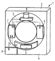
図1はCT設備の回転部分の個々の構成要素間の主たる接続の例を示し、CT設備1のガン
トリー2は回転部分3と固定部分4を有する。回転部分3の内部には、X線管ユニット6
及びこのX線管ユニット6に対向して置かれた測定装置5が認められる。X線管ユニット
6は、X線管、コリメータ、焦点制御装置及びアノード回転のための装置を含む。測定装
置5はX線検出器及び所属の評価ユニットを含む。さらにガントリー2の回転部分3には
、回転部分及び線量変調のためのマスタコントローラ7並びに高周波発生器及び回転のた
めの電源を有する電圧給電部9が配置されている。個々の制御信号及びデータ又はそのい
ずれか一方は、マスタコントローラ7から各構成要素へ伝送されるか、又はマスタコント
ローラ7によって受け取られる。このことは図1において矢印で示されている。回転部分
3におけるマスタコントローラ7は、ガントリー2の固定部分4におけるマスタコントロ
ーラ8と結ばれている。両マスタコントローラ間の信号及びデータ伝送は、ガントリーの
回転部分及び固定部分に取り付けられている対応するスリップリング対を介して行うこと
ができる。
FIG. 1 shows an example of the main connections between the individual components of the rotating part of the CT equipment, the
And the measuring device 5 placed opposite to the
図2は再びCT設備のガントリー2を示し、この例では移動可能な患者台10、画像再生
システム12及び電圧分割部を持ったユニット11を有する。ここでも固定したマスタコ
ントローラ8は接続線を介して対応する構成要素と結ばれ、接続線を介して制御信号及び
ディジタルデータが伝送ないし交換される。その状態は矢印で示されている。この場合個
々の矢印は一般に多数の導線、例えば個々の部分システムの制御のためのアナログ信号線
及びディジタル測定データの伝送のためのCANネットワーク接続を表わす。
FIG. 2 again shows a
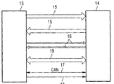
現在のCT設備において2つの部分システム、以下ではマスタコントローラ7、8を表わ
すマスタ部分システム13及びスレーブ部分システム14という2つの部分システム間に
使用される多数の接続線は、図3から知ることができる。この場合、伝送線15を介して
NないしMの微分の、光学的に絶縁された論理信号、例えばenable_xray、xxx_error、な
いしxray_on、dose_ok、xxx_error、等が伝送される。伝送線16はKの微分アナログ
信号の一方向への伝送ないしLの微分アナログ信号の他の方向への伝送のための電気導線
を表わす。さらに一般にはディジタルデータの直接伝送のためにCAN接続17が設けられ
ている。例えば230VAC、5VDC、−5VDC、24VDC等の異なる電圧のための多数の給電線18
の他に、符号19でCT設備の改造の際他の信号を後にインプリメントするために必要とな
る補助の敷設ケーブルも示されている。
A number of connection lines used between two partial systems in the current CT installation, two partial systems, in the following master
N to M differential, optically isolated logic signals such as enable_xray, xxx_error, or xray_on, dose_ok, xxx_error, etc. are transmitted.
In addition,
CT設備においてマスタコントローラ7ないし8と部分システムの1つとの間のみならず
個々の部分システム間に生ずる異なる接続プロトコルを有する多数の接続線は、多数の伝
送コンポーネントを必要とし、またさらにCT設備の拡張の際に極めて費用がかかることに
なる。それに対し本発明の方法を使用する場合には、図4に概略示すように接続線の数が
劇的に減少される。この方法を実施する場合、マスタ部分システム13とスレーブ部分シ
ステム14との間に1つ又は2つの伝送線20及び230VAC又は24VDCの単一の給電線21
のみを必要とするだけである。これらの部分システムの側にそれぞれ必要なデータ伝送及
び制御装置22は、この実施例では既知のSERDESコンポーネント23、それに所属する送
信器24及び受信器25から構成されている。SERDESコンポーネント23は、伝達すべき
信号及びデータを本方法により設定された形で送り、ないしは受けた信号及びデータを各
構成要素の対応するコンポーネントに転送する。
Multiple connection lines with different connection protocols that arise between the individual partial systems as well as between the master controllers 7 to 8 and one of the partial systems in the CT installation require multiple transmission components, and furthermore the CT installation It will be very expensive to expand. On the other hand, when using the method of the present invention, the number of connecting lines is dramatically reduced as shown schematically in FIG. In carrying out this method, one or two
Need only. The necessary data transmission and
この実施例においては、伝達は1.25Gbpsの速度で小さなデータパケットで両方向に行わ
れる。伝送は、例えば100Mbpsイーサネット(登録商標)、ギガバイト・イーサネット(登録商標)、インフィニバンド等のような多くの他の公知の伝送プロトコルで使用される既知の8B/10B変換で行われる。8B/10B変換は直流電圧を含まないビット電流にデータ及びクロック信号を埋め込み、このビット電流は受信器に、クロックによる同期化、個々のビットの信頼できるデコード及びバイト限界の検出を可能にする。
In this embodiment, transmission takes place in both directions with small data packets at a rate of 1.25 Gbps. Transmission takes place with the known 8B / 10B conversion used in many other known transmission protocols such as 100 Mbps Ethernet, Gigabyte Ethernet, InfiniBand, etc. The 8B / 10B conversion embeds the data and clock signal in a bit current that does not contain a DC voltage, which enables the receiver to synchronize with the clock, reliably decode individual bits, and detect byte limits.
データパケットのフォーマットは、本方法においては自由に選択することができ、各要
求に適合される。データ伝送及び制御装置を関与する構成要素の各々においてFPGAにイン
プリメントすることによって、使用されるデータフォーマットも使用される伝送プロトコ
ルもそれらの更新及び変更をいつでも行うことができる。
The format of the data packet can be chosen freely in the method and is adapted to each requirement. By implementing the data transmission and control device in each of the components involved in the FPGA, the data format used and the transmission protocol used can be updated and changed at any time.
可能なデータフォーマットの一例を以下にしめす。データパケットのフォーマットは両
伝送方向に等しく選ばれる。データパケットはマルチプレクシングされディジタル化され
た信号、及び自由に、例えばバイト形式で16ビット語又は32ビット語として規定され得る
ディジタルデータ値を含む。各データパケットは先行する制御コード(コンマ‐K28.5)
により自己同期化されており、同定及び誤り検出のための1バイト・CRCコード(巡回符
号)を備えている。このようなデータパケットの構成が次の表1に示されている。
An example of a possible data format is shown below. The format of the data packet is chosen equally in both transmission directions. Data packets contain multiplexed and digitized signals and digital data values that can be freely defined as, for example, 16-bit words or 32-bit words in byte form. Each data packet is preceded by a control code (Comma-K28.5)
Is self-synchronized with a 1-byte CRC code (cyclic code) for identification and error detection. The structure of such a data packet is shown in Table 1 below.

従ってデータパケットは、受信器における自動バイト同期化を可能にするため、個々の
パケット間に補助のアイドルバイト(同期して又はコンマともいわれる)を有する12バイ
トを含む。その際バイトレートは1.25Gbpsの場合125Mbyte/sである。従って伝送の際のパ
ケットレートは1パケットがすべて104ns又は9.6Mpacket/sの値を有する。
Thus, the data packet includes 12 bytes with an auxiliary idle byte (synchronously or also referred to as a comma) between individual packets to allow automatic byte synchronization at the receiver. In this case, the byte rate is 125 Mbyte / s for 1.25 Gbps. Accordingly, the packet rate for transmission has a value of 104 ns or 9.6 Mpacket / s for all packets.
各パケットはその際マルチプレクシングされディジタル化された信号及びディジタルデ
ータを運ぶ。ここでディジタル化された信号とは、とりわけ、従来別の線を介して伝送さ
れた、特にアナログの、信号を意味し、比較的早く変化し得るものであり、従って高い更新度を要求する。本実施例ではこれらの信号の各々はすべてほぼ77〜150ビット周期の
レーテンシー時間でもって104nsごとに更新される。それ故これらの信号の更新の際の最大遅れは224ns(150×0.8ns=120ns;120ns+104ns=224ns)である。このことはCT設備において必要な制御信号に対し十分である。
Each packet then carries a multiplexed and digitized signal and digital data. The digitized signal here means in particular an analog signal, which has been transmitted conventionally over another line, and can change relatively quickly, and therefore requires a high degree of update . In this embodiment, each of these signals is all updated every 104 ns with a latency time of approximately 77-150 bit periods. Therefore, the maximum delay in updating these signals is 224 ns (150 × 0.8 ns = 120 ns; 120 ns + 104 ns = 224 ns). This is sufficient for the control signals required in CT equipment.
本例においては、すべて104nsの各パケットによりディジタルデータを有する32ビット
ブロックが各構成要素間で動かされる。このディジタルデータを有するブロックは、ディ
ジタルデータに対し又はディジタル化されたアナログ信号に対し多数の仮の伝送チャネル
を得るため、伝送フォーマットに関係して補助的にマルチプレクシングされ得る。このよ
うな多数チャネル伝送のための一例を以下に詳細に説明する。
In this example, a 32-bit block with digital data is moved between each component with every packet of 104 ns. This block with digital data can be auxiliary multiplexed in relation to the transmission format in order to obtain a number of temporary transmission channels for the digital data or for the digitized analog signal. An example for such multi-channel transmission is described in detail below.
この例においては、それぞれ8つの連続するパケットが1つのフレームにまとめられる
。その際各パケットはデータ伝送の時間スリットを表わし、その時間スリットにおいては
他のチャネルが伝送される。そのため8つのデータパケットのそれぞれにおける各ブロッ
クのディジタルデータは他のチャネルのデータを表わし、その結果各チャネルのデータは
それぞれ8つのデータパケット、1つのフレームの伝送後に再び更新される。個々のチャネルのより急速な更新が必要であるべき場合には、もちろん同じフレームにおける対応するチャネルが多重に、例えば各2番目のデータパケットと共に伝送されることも可能である。次の表2は8つの時間スリットを有する多チャネルフレームの構造を示す。その
際各チャネルのデータはすべて0.84μsごとに更新され、その結果これに関して各チャネルに対し32ビット/μsの正味伝送度が生ずる。
In this example, eight consecutive packets are each combined into one frame. Each packet then represents a data transmission time slit in which other channels are transmitted. Therefore, the digital data of each block in each of the eight data packets represents the data of the other channel, so that the data of each channel is updated again after transmission of each of the eight data packets and one frame. If more rapid updates of individual channels are to be required, of course, the corresponding channels in the same frame can be transmitted in multiples, for example with each second data packet. The following Table 2 shows the structure of a multi-channel frame with 8 time slits. The data for each channel is then updated every 0.84 μs, resulting in a net transmission of 32 bits / μs for each channel in this regard.
CT設備の場合には、個々のチャネルは例えば次のデータ及び信号の伝送で占められ得る
。
・高電圧値、線量値等の伝達のためのX線チャネル、
・EKG信号、脈拍及び呼吸データの伝送のための患者監視チャネル、
・台位置、ガントリーの傾き及び回転速度等の伝送のためのガントリーチャネル、
・仮の論理解析チャネル及びデバッグチャネル(マルチプレクシングされた情報)、
・制御情報チャネル、即ち全CANプロトコル、
・CTシステムの実時間クロックの伝送のためのチャネル、
・65536×16ビットの仮レジスタへの読み取りないし書き込みアクセスのためのメモリチ
ャネル、
・伝送誤りの訂正のための誤り検出符号を伝送するためのチャネル
In the case of CT equipment, the individual channels can be occupied, for example, by the transmission of the following data and signals.
-X-ray channel for transmission of high voltage values, dose values, etc.
A patient monitoring channel for transmission of EKG signals, pulse and respiratory data,
・ Gantry channel for transmission of platform position, gantry tilt and rotation speed,
・ Temporary logic analysis channel and debug channel (multiplexed information),
Control information channel, ie all CAN protocols,
-Channel for real-time clock transmission of CT system,
A memory channel for read or write access to a 65536 x 16-bit temporary register,
.Channel for transmitting error detection codes for correcting transmission errors
メモリチャネルの装置は、仮の16ビットアドレス×16ビットデータ領域へのアクセスを
可能にする。所属のプロトコルは、3つのパケット識別器及びハンドシェイク原理に基づ
くデータ交換を基礎に65536×16ビットの仮レジスタにおける必要な読み取り及び書き込
み過程を可能にすることができる。アクセスのための一例が、読み取りシーケンス及び書
き込みシーケンスを示す次の2つの表3、表4に示されている。
The memory channel device enables access to a temporary 16-bit address × 16-bit data area. The protocol to which it belongs can enable the necessary read and write processes in a 65536 × 16 bit temporary register based on data exchange based on three packet identifiers and handshake principle. An example for access is shown in the following two Tables 3, 4 showing the read and write sequences.
読み取りシーケンス
書き込みシーケンス
メモリアクセスは、2つ及び3つの時間スリット間に必要とし、その結果メモリアクセ
スは時間スリット間の位相ずれに関係して両接続方向に約2〜2.5μs内に行うことができ
る。このアクセスは平均的に、速い命令の実行のために約0.5〜1ms必要とするCANを介し
てのアクセスより十分に速い。
Memory access is required between two and three time slits, so that memory access can be made in about 2 to 2.5 μs in both connection directions in relation to the phase shift between the time slits. This access is on average much faster than access via CAN, which requires about 0.5-1 ms for fast instruction execution.
メモリチャネルの準備と同じようにして、従来CANネットワークを介して行われる通信
も仮のチャネルを介して行うことができる。本例の場合のように1.25Gbps(1μsごとに32
ビット)で行われるデータ接続における速度は、仮のチャネルへCAN情報(CAN250kHzの場
合33msで32ビット)のインプリメントを可能にし、その結果マスタとスレーブとの間の別
々の並列CAN接続はなくなることが可能である。本コンフィギュレーションにおいては従
ってCAN情報は、特別にそのために設けられ、現在使用されるようなCAN伝送線におけるよ
り約33000倍速く伝達される。
In the same way as the preparation of the memory channel, the communication conventionally performed via the CAN network can also be performed via the temporary channel. 1.25Gbps (32 for every 1μs as in this example)
The speed of the data connection made in (bit) allows the implementation of CAN information (32 bits at 33 ms for CAN 250 kHz) on a temporary channel, so that there is no separate parallel CAN connection between master and slave Is possible. In this configuration, therefore, the CAN information is specially provided for that and is transmitted approximately 33000 times faster than on CAN transmission lines as currently used.
もちろんCAN情報は各パケットにより伝達されるディジタル化された信号のブロックと
共に伝送することができ、その結果さらに迅速な伝送が生ずる。このような構成において
は、例えばJTAG、TCP/IPのような他のバスシステムも本接続を介して伝送することができ
る。
Of course, the CAN information can be transmitted with a block of digitized signals carried by each packet, resulting in faster transmission. In such a configuration, other bus systems such as JTAG and TCP / IP can also transmit via this connection.
データ伝送及び制御装置は、伝送プロトコルのインプリメント並びに信号及びディジタ
ルデータの送信及び受信並びに分割に使用される。有利な構成においては、データ伝送及
び制御装置は伝送プロトコルにおける簡単な再コンフィギュレーション又は変更を可能に
するため、プログラミング可能なFPGAにインプリメントされている。再コンフィギュレー
ションのためには種々のやり方が可能である。
Data transmission and control devices are used to implement transmission protocols and to transmit and receive and split signals and digital data. In an advantageous configuration, the data transmission and control device is implemented in a programmable FPGA to allow simple reconfiguration or change in the transmission protocol. Various ways are possible for reconfiguration.
設備になおマスタとスレーブ部分システム間に並列の独立したCAN接続が存在する場合
には、FPGAコンフィギュレーションの更新がCANを介して行われる。マスタは新しいFPG
AコンフィギュレーションをCANによりスレーブ・マイクロコントローラに伝達する。新し
いコンフィギュレーションは、ローカルの不揮発性メモリ内で確保される。各パワーアッ
プシーケンスにより、各FPGAのマイクロコントローラはそれぞれの最後の有効であったコ
ンフィギュレーションにより充電される。
If the facility still has independent CAN connections in parallel between the master and slave subsystems, the FPGA configuration is updated via CAN. Master is a new FPG
A configuration is communicated to the slave microcontroller via CAN. The new configuration is reserved in local non-volatile memory. With each power-up sequence, each FPGA microcontroller is charged with its last valid configuration.
例えばCAN情報の伝送が本接続を介して行われるために、独立したCAN接続が自由に使用できない場合には、FPGAコンフィギュレーションの更新は特別の信号を介して本接続上
で行うことができる。しかしこのことは一般に、それぞれ接続に関与する構成要素の同時
の更新を必要とする。
If, for example, CAN information is transmitted over this connection and an independent CAN connection cannot be used freely, the FPGA configuration can be updated over the connection via a special signal. However, this generally requires simultaneous updates of the components involved in each connection.
コンフィギュレーションのこのような更新の実施の有利な可能性は、システムのインプリメントにおいて、少なくとも更新プロトコルを支援するベースFPGAコンフィギュレーションを設定することにある。更新プロトコルはパケットと無関係で、システムの全寿命期間中変更されない。更新プロセスの際、マスタから制御コードのあらかじめ定義されたシーケンスが接続を介して伝送されることにより、スレーブ部分ユニットがコンフィギュレーションモードにセットされる。スレーブ部分システムは制御コードの定義されたシーケンスの返送によりコンフィギュレーションモードの交換を確認する。更新の際、コンフィギュレーションプロトコルがすべての将来のFGPAコンフィギュレーションによっても維持されることが保証される。 An advantageous possibility of performing such an update of the configuration is to set a base FPGA configuration that supports at least the update protocol in the implementation of the system. The update protocol is independent of the packet and does not change during the entire lifetime of the system. During the update process, a predefined sequence of control codes is transmitted over the connection from the master, so that the slave partial unit is set to the configuration mode. The slave sub-system confirms the configuration mode exchange by returning a defined sequence of control codes. Upon update , it is guaranteed that the configuration protocol will be maintained with all future FGPA configurations.
スレーブ部分システムのコンフィギュレーションモードへの交換後、マスタは通常のパ
ケットの代わりにコンフィギュレーションデータのみを送る。コンフィギュレーションデ
ータの損傷のないことを例えば検査合計、CRC等を介して調べた後、スレーブ部分システ
ムは新しいコンフィギュレーションをフラッシュメモリ又はローカルのコンフィギュレー
ションPROMに記憶する。引き続くオフオンの後又はリセットシーケンスの後、新しいコン
フィギュレーションが接続の両側に調整されている。
After switching the slave partial system to configuration mode, the master sends only configuration data instead of normal packets. After checking the configuration data for damage, for example via checksum, CRC, etc., the slave sub-system stores the new configuration in flash memory or local configuration PROM. After a subsequent off-on or reset sequence, the new configuration has been adjusted on both sides of the connection.
本例においては、直列のビット流の信頼できるデコーディングのための伝送クロックへ
の同期化を得るため、速い接続のためにPLLを有する8B/10B SERDESコンポーネントが使用
される。このSERDESコンポーネントのインプリメントのためにはASICを使用した解決法が
有利である。何故ならこのASICは、このような用途に微調整されている通常アナログPLL
を結び付けられて持っているからである。ただしこの解決法は長いレーテンシー時間を含
む。それ故それに代えて、もっと短い内部レーテンシー時間を持つ積分型SERDESを備えた
FPGAを使用することができる。
In this example, an 8B / 10B SERDES component with a PLL is used for fast connection to obtain synchronization to the transmission clock for reliable decoding of the serial bit stream. A solution using ASIC is advantageous for implementing this SERDES component. Because this ASIC is usually an analog PLL that is fine-tuned for such applications
It is because it is tied. However, this solution involves long latency times. Instead, it has integrated SERDES with shorter internal latency time.
FPGA can be used.
データ伝送及び制御装置の構成並びに伝送線の構成に対して異なる可能性が存在し、そ
れらについて以下4つの図5〜8に4つの構成例を示す。
There are different possibilities for the configuration of the data transmission and control device and the configuration of the transmission line, and for these, four configuration examples are shown in FIGS.
図5は、各構成要素におけるデータ伝送及び制御装置22がFPGA26にインプリメント
され、ASICにより実現されたSERDES23と結ばれた構成が示されている。それぞれの送信
器及び受信器は光送信器24a及び光受信器25aとして形成され、光導線20aを介して
伝送が行われる。この構成は電磁的干渉を減らし、2.5Gbpsまでの伝送レートへのアップ
グレードを可能にし、さらに長い導線路及び電気的絶縁を可能にする。全体としてこのよ
うなシステムは擾乱に対し極めて強い。
FIG. 5 shows a configuration in which the data transmission and
光式送信器及び受信器のコストがかなり高いことに基づき、もちろん図6に示すように
電気導線を介して送信及び受信する送信器24b及び受信器25bを有する構成も可能であ
る。この場合伝送はツインアックス又はコアックスケーブル20bを介して行われる。こ
の構成は、そのほかのコンポーネントは同じものを使用する場合、図5の構成よりコスト
的に有利に実現することができる。
Based on the considerable cost of optical transmitters and receivers, it is of course possible to have a
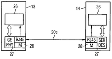
図7は伝送がギガビット・イーサネット(登録商標)・ケーブル及びアダプタを介して行われる構成を示す。このデータ伝送及び制御装置の部分が先行の構成の場合と同じようにFPGA26にインプリメントされている構成においては、データ伝送のためにギガビット・イーサネット(登録商標) PHYアダプタ27が使用され、その際伝送は公知のRJ45インタフェースを介して単一のCAT5ケーブル20cにより行われる。電気的絶縁は公知のやり方で磁気コンポーネント28を介して行われる。この構成は一般のコンポーネントに基づいて極めてコスト的に有利に実現することができる。
FIG. 7 shows a configuration in which transmission is performed via a Gigabit Ethernet (registered trademark) cable and an adapter. In the structure portion of the data transmission and control device are the same as in flop decrements the FPGA26 the case of the configuration of the prior, Gigabit Ethernet (registered trademark)
若干のCT構成要素間を接続する場合、伝送のための本発明による迅速な接続より多く使
用することが必要になる場合があり得る。このような場合には、データ伝送及び制御装置
(22)又はその一部は同様にFPGA(26)へのインプリメントにより実現することがで
き、このFPGAは複数の送信器/受信器(24/25)を持った複数のSERDES形成ブロック
を備え、このことは図8に示されている。その際送信器ないし受信器及び接続線の構成は
、公知のやり方で、例えば先行の実施例において説明したと同じように行うことができる
。その際適切なコンポーネントとしては、例えばAltera Stratix GX-Familie、24I/Oトラ
ンシーバを有するXilinx Virtex-II Pro又は8つのトランシーバを有するLattice ORCA 8
2G5が考慮の対象になる。ギガビット・イーサネット(登録商標)・ケーブルを介しての迅速な接続のためには、例えばBroadcomのBCM5402(デュアルポート)又はBCM5421(クァドポート)トランシーバを使用することができる。
When connecting between some CT components, it may be necessary to use more than the quick connection according to the invention for transmission. In such a case, the data transmission and control unit (22) or part of it can also be realized by an implementation in the FPGA (26), which FPGA comprises a plurality of transmitter / receivers (24/25). ) With a plurality of SERDES building blocks, which is illustrated in FIG. The configuration of the transmitter or receiver and the connecting lines can then be carried out in a known manner, for example as described in the previous embodiments. Suitable components include, for example, Altera Stratix GX-Familie, Xilinx Virtex-II Pro with 24I / O transceivers or Lattice ORCA 8 with 8 transceivers.
2G5 is a consideration. For quick connection via Gigabit Ethernet cable, for example, a Broadcom BCM5402 (dual port) or BCM5421 (quad port) transceiver can be used.
1 CT設備
2 ガントリー
3 ガントリーの回転部分
4 ガントリーの固定部分
5 測定装置
6 X線管ユニット
7 マスタコントローラ(回転)
8 マスタコントローラ(固定)
9 電圧給電部(回転)
10 患者台
11 電圧分割部を有するユニット
12 画像再生システム
13 マスタ部分システム
14 スレーブ部分システム
15 論理信号のための伝送線
16 アナログ信号のための伝送線
17 CAN接続
18 給電線
19 将来の信号のための補助敷設ケーブル
20 伝送線
20a 光ケーブル
20b ツインアックス又はコアックス・ケーブル
20c CAT5ケーブル
21 給電線
22 データ伝送及び制御装置
23 SERDESコンポーネント
24 送信器
24a 光式送信器
24b 電気式送信器
25 受信器
25a 光式受信器
25b 電気式受信器
26 FPGA
27 ギガビット・イーサネット(登録商標)PHYアダプタ
28 磁気コンポーネント
1
8 Master controller (fixed)
9 Voltage feeder (rotation)
DESCRIPTION OF
27 Gigabit
Claims (19)
Applications Claiming Priority (2)
| Application Number | Priority Date | Filing Date | Title |
|---|---|---|---|
| DE10354494.1 | 2003-11-21 | ||
| DE10354494.1A DE10354494B4 (en) | 2003-11-21 | 2003-11-21 | Method for data and signal transmission between different subunits of a medical device |
Publications (2)
| Publication Number | Publication Date |
|---|---|
| JP2005160072A JP2005160072A (en) | 2005-06-16 |
| JP5264041B2 true JP5264041B2 (en) | 2013-08-14 |
Family
ID=34625178
Family Applications (1)
| Application Number | Title | Priority Date | Filing Date |
|---|---|---|---|
| JP2004335407A Active JP5264041B2 (en) | 2003-11-21 | 2004-11-19 | Data and signal transmission method between components of medical equipment |
Country Status (4)
| Country | Link |
|---|---|
| US (1) | US7673081B2 (en) |
| JP (1) | JP5264041B2 (en) |
| CN (1) | CN1620030A (en) |
| DE (1) | DE10354494B4 (en) |
Families Citing this family (17)
| Publication number | Priority date | Publication date | Assignee | Title |
|---|---|---|---|---|
| US7593498B2 (en) * | 2006-09-29 | 2009-09-22 | Agere Systems Inc. | Method and apparatus for automatic rate identification and channel synchronization in a master-slave setting for high data throughput applications |
| DE102007025079B4 (en) * | 2007-05-30 | 2009-08-06 | Siemens Ag | X-ray system |
| FR2927212B1 (en) * | 2008-02-01 | 2010-07-30 | Centre Nat Rech Scient | PROCESS FOR RECONFIGURING A SET OF COMPONENTS OF AN ELECTRONIC CIRCUIT, RECONFIGURATION SYSTEM AND CORRESPONDING DATA TRANSMISSION PROTOCOL. |
| EP2109244A1 (en) * | 2008-04-09 | 2009-10-14 | Siemens Aktiengesellschaft | Method for security-oriented transmission, security switch device and control unit |
| US20100208777A1 (en) * | 2009-02-17 | 2010-08-19 | Adc Telecommunications, Inc. | Distributed antenna system using gigabit ethernet physical layer device |
| CN103220971B (en) | 2010-11-08 | 2017-08-25 | 皇家飞利浦电子股份有限公司 | Low delay signal on digital network is sent |
| DE102012201222A1 (en) * | 2012-01-27 | 2013-08-01 | Siemens Aktiengesellschaft | Medical facility |
| DE102012213948B4 (en) * | 2012-08-07 | 2021-05-06 | Siemens Healthcare Gmbh | Device, method and system for controlling imaging methods and systems |
| DE102014206007A1 (en) * | 2014-03-31 | 2015-10-01 | Siemens Aktiengesellschaft | Scalable and flexible hardware topology of a CT detector |
| CN107249454B (en) * | 2015-02-24 | 2020-12-18 | 皇家飞利浦有限公司 | Method for planning a scan geometry for MRI or CT |
| DE102016213379A1 (en) * | 2016-07-21 | 2018-01-25 | Siemens Healthcare Gmbh | Method for operating an X-ray device and associated X-ray device |
| DE102016221221A1 (en) | 2016-10-27 | 2018-05-03 | Siemens Healthcare Gmbh | Data transmission between an X-ray detector and a computing unit by means of network protocol |
| EP3441780A1 (en) | 2017-08-09 | 2019-02-13 | Siemens Healthcare GmbH | Sheath wave-free connection line, and magnetic resonance tomograph with connection line |
| CN111093507B (en) * | 2017-09-13 | 2021-09-21 | 万睿视影像有限公司 | X-ray imaging component communication system and protocol |
| EP3477650B1 (en) * | 2017-10-25 | 2022-11-23 | Siemens Healthcare GmbH | Medical imaging device and method and device for communication in a medical imaging device |
| CN109528220B (en) * | 2018-11-29 | 2023-05-30 | 上海联影医疗科技股份有限公司 | Method and device for adjusting an electronic computed tomography system and computer device |
| DE102020204681B4 (en) | 2020-04-14 | 2022-08-04 | Siemens Healthcare Gmbh | Image recording system for a computed tomography system and method for configuring the same |
Family Cites Families (21)
| Publication number | Priority date | Publication date | Assignee | Title |
|---|---|---|---|---|
| US4764939A (en) * | 1985-12-02 | 1988-08-16 | Telenex Corporation | Cable system for digital information |
| US4974181A (en) * | 1988-04-15 | 1990-11-27 | The United States Of America As Represented By The Adminstrator, Of The National Aeronautics And Space Administration | Adaptive data acquisition multiplexing system and method |
| US5025458A (en) * | 1989-10-30 | 1991-06-18 | International Business Machines Corporation | Apparatus for decoding frames from a data link |
| US5272627A (en) * | 1991-03-27 | 1993-12-21 | Gulton Industries, Inc. | Data converter for CT data acquisition system |
| FR2727221B1 (en) * | 1994-11-23 | 1996-12-27 | Kodak Pathe | METHOD FOR COMMUNICATING DIGITAL INFORMATION AND SYSTEM FOR IMPLEMENTING THE METHOD |
| US5646962A (en) * | 1994-12-05 | 1997-07-08 | General Electric Company | Apparatus for reducing electromagnetic radiation from a differentially driven transmission line used for high data rate communication in a computerized tomography system |
| US5742060A (en) * | 1994-12-23 | 1998-04-21 | Digirad Corporation | Medical system for obtaining multiple images of a body from different perspectives |
| JPH10340243A (en) * | 1997-06-06 | 1998-12-22 | Hitachi Ltd | Input/output data transfer system |
| US6292919B1 (en) * | 1998-08-25 | 2001-09-18 | General Electric Company | Methods and apparatus for exchanging data in an imaging system |
| US6301324B1 (en) * | 1999-03-31 | 2001-10-09 | General Electric Company | RF slipring receiver for a computerized tomography system |
| US6609472B2 (en) | 1999-09-01 | 2003-08-26 | Paulette Renee Burg | Stable efficient air lubricated ship |
| US6577417B1 (en) * | 2000-08-19 | 2003-06-10 | Jehad Khoury | Heterodyne-wavelength division demultiplexing for optical pick-ups, microscopy, tomography telecommunication and lidar |
| EP1206099A3 (en) * | 2000-11-14 | 2003-10-22 | Sancastle Technologies Ltd. | Network interface |
| US6708239B1 (en) * | 2000-12-08 | 2004-03-16 | The Boeing Company | Network device interface for digitally interfacing data channels to a controller via a network |
| JP2002217932A (en) * | 2001-01-16 | 2002-08-02 | Nippon Telegr & Teleph Corp <Ntt> | Optical access network system |
| DE10102323A1 (en) * | 2001-01-19 | 2002-07-25 | Philips Corp Intellectual Pty | Method and device for the reliable transmission of data packets |
| US6470071B1 (en) | 2001-01-31 | 2002-10-22 | General Electric Company | Real time data acquisition system including decoupled host computer |
| US6862299B2 (en) * | 2001-04-12 | 2005-03-01 | Siemens Aktiengesellschaft | Method and system for galvanically isolated transmission of gigabit/sec data via a slip ring arrangement |
| JP3879836B2 (en) * | 2002-03-28 | 2007-02-14 | 日本電気株式会社 | Multiplex converter, demultiplexer, and multiplex transmission system |
| US20030214953A1 (en) * | 2002-05-14 | 2003-11-20 | Ge Medical Systems Global Technology Company, Llc | Networked magnetic resonance imaging system and method incorporating same |
| US6904118B2 (en) * | 2002-07-23 | 2005-06-07 | General Electric Company | Method and apparatus for generating a density map using dual-energy CT |
-
2003
- 2003-11-21 DE DE10354494.1A patent/DE10354494B4/en not_active Expired - Lifetime
-
2004
- 2004-11-19 JP JP2004335407A patent/JP5264041B2/en active Active
- 2004-11-19 US US10/992,859 patent/US7673081B2/en active Active
- 2004-11-22 CN CNA2004100952928A patent/CN1620030A/en active Pending
Also Published As
| Publication number | Publication date |
|---|---|
| US7673081B2 (en) | 2010-03-02 |
| JP2005160072A (en) | 2005-06-16 |
| US20050169263A1 (en) | 2005-08-04 |
| CN1620030A (en) | 2005-05-25 |
| DE10354494B4 (en) | 2019-04-11 |
| DE10354494A1 (en) | 2005-06-30 |
Similar Documents
| Publication | Publication Date | Title |
|---|---|---|
| JP5264041B2 (en) | Data and signal transmission method between components of medical equipment | |
| JP4702876B2 (en) | data communication | |
| EP1460794B1 (en) | Synchronisation of data communication | |
| EP2824845B1 (en) | Two-wire communication protocol engine | |
| US20210320737A1 (en) | Open real-time ethernet protocol | |
| GB2407006A (en) | Communicating streamed payload data and packet based auxiliary data | |
| CN111727589A (en) | Method and device for configuring Flex Ethernet node | |
| JP2006127514A (en) | Modular system numerical control device having low-jitter synchronization | |
| CN109327365B (en) | Method for transmitting data between a rotation angle sensor and an engine control device or evaluation unit | |
| Gutiérrez et al. | The ALICE TPC readout control unit | |
| JP5457230B2 (en) | Protection relay device and current differential protection relay device | |
| US7729374B2 (en) | Fibre channel interface apparatus and methods | |
| WO2016172765A1 (en) | A system for multiplexing a plurality of payloads and a method for multiplexing a plurality of payloads | |
| ES2295618T3 (en) | METHOD FOR THE OPERATION OF A POSITION MEASUREMENT DEVICE AND MEASUREMENT POSITION DEVICE FOR THE SAME. | |
| Kim et al. | High speed ring-based distributed networked control system for real-time multivariable applications | |
| US10374734B1 (en) | Multi-tier time-synchronization architecture | |
| Depari et al. | Multi-probe measurement instrument for real-time ethernet networks | |
| EP4304114A1 (en) | Wavelength configuration apparatus and system, and wavelength configuration method | |
| CN219814148U (en) | Detector for a computed tomography scanner and computed tomography system | |
| Hulsart et al. | Fast BPM data distribution for global orbit feedback using commercial gigabit Ethernet technology | |
| CN110663230B (en) | Local bus master and method for operating a local bus | |
| Matheson | SynqNet: high performance motion control based on Ethernet | |
| WO2024037744A1 (en) | High density rotary joint for contactless data transfer | |
| CN113645322A (en) | Address code identification method and device based on optical fiber serial communication and application thereof | |
| Ameli | The NEMO floor control module |
Legal Events
| Date | Code | Title | Description |
|---|---|---|---|
| A621 | Written request for application examination |
Free format text: JAPANESE INTERMEDIATE CODE: A621 Effective date: 20071105 |
|
| A977 | Report on retrieval |
Free format text: JAPANESE INTERMEDIATE CODE: A971007 Effective date: 20100726 |
|
| A131 | Notification of reasons for refusal |
Free format text: JAPANESE INTERMEDIATE CODE: A131 Effective date: 20100803 |
|
| A601 | Written request for extension of time |
Free format text: JAPANESE INTERMEDIATE CODE: A601 Effective date: 20101102 |
|
| A602 | Written permission of extension of time |
Free format text: JAPANESE INTERMEDIATE CODE: A602 Effective date: 20101108 |
|
| A601 | Written request for extension of time |
Free format text: JAPANESE INTERMEDIATE CODE: A601 Effective date: 20101203 |
|
| A602 | Written permission of extension of time |
Free format text: JAPANESE INTERMEDIATE CODE: A602 Effective date: 20101208 |
|
| A601 | Written request for extension of time |
Free format text: JAPANESE INTERMEDIATE CODE: A601 Effective date: 20101229 |
|
| A602 | Written permission of extension of time |
Free format text: JAPANESE INTERMEDIATE CODE: A602 Effective date: 20110107 |
|
| A521 | Request for written amendment filed |
Free format text: JAPANESE INTERMEDIATE CODE: A523 Effective date: 20110125 |
|
| RD03 | Notification of appointment of power of attorney |
Free format text: JAPANESE INTERMEDIATE CODE: A7423 Effective date: 20110125 |
|
| A131 | Notification of reasons for refusal |
Free format text: JAPANESE INTERMEDIATE CODE: A131 Effective date: 20110222 |
|
| A521 | Request for written amendment filed |
Free format text: JAPANESE INTERMEDIATE CODE: A523 Effective date: 20110518 |
|
| A02 | Decision of refusal |
Free format text: JAPANESE INTERMEDIATE CODE: A02 Effective date: 20110607 |
|
| A521 | Request for written amendment filed |
Free format text: JAPANESE INTERMEDIATE CODE: A523 Effective date: 20111006 |
|
| A911 | Transfer to examiner for re-examination before appeal (zenchi) |
Free format text: JAPANESE INTERMEDIATE CODE: A911 Effective date: 20111013 |
|
| A912 | Re-examination (zenchi) completed and case transferred to appeal board |
Free format text: JAPANESE INTERMEDIATE CODE: A912 Effective date: 20111111 |
|
| A601 | Written request for extension of time |
Free format text: JAPANESE INTERMEDIATE CODE: A601 Effective date: 20120905 |
|
| A602 | Written permission of extension of time |
Free format text: JAPANESE INTERMEDIATE CODE: A602 Effective date: 20120911 |
|
| A601 | Written request for extension of time |
Free format text: JAPANESE INTERMEDIATE CODE: A601 Effective date: 20121002 |
|
| A602 | Written permission of extension of time |
Free format text: JAPANESE INTERMEDIATE CODE: A602 Effective date: 20121005 |
|
| A601 | Written request for extension of time |
Free format text: JAPANESE INTERMEDIATE CODE: A601 Effective date: 20121102 |
|
| A602 | Written permission of extension of time |
Free format text: JAPANESE INTERMEDIATE CODE: A602 Effective date: 20121107 |
|
| A521 | Request for written amendment filed |
Free format text: JAPANESE INTERMEDIATE CODE: A523 Effective date: 20130220 |
|
| A521 | Request for written amendment filed |
Free format text: JAPANESE INTERMEDIATE CODE: A523 Effective date: 20130305 |
|
| A61 | First payment of annual fees (during grant procedure) |
Free format text: JAPANESE INTERMEDIATE CODE: A61 Effective date: 20130430 |
|
| R150 | Certificate of patent or registration of utility model |
Ref document number: 5264041 Country of ref document: JP Free format text: JAPANESE INTERMEDIATE CODE: R150 Free format text: JAPANESE INTERMEDIATE CODE: R150 |
|
| R250 | Receipt of annual fees |
Free format text: JAPANESE INTERMEDIATE CODE: R250 |
|
| R250 | Receipt of annual fees |
Free format text: JAPANESE INTERMEDIATE CODE: R250 |
|
| R250 | Receipt of annual fees |
Free format text: JAPANESE INTERMEDIATE CODE: R250 |
|
| R250 | Receipt of annual fees |
Free format text: JAPANESE INTERMEDIATE CODE: R250 |
|
| R250 | Receipt of annual fees |
Free format text: JAPANESE INTERMEDIATE CODE: R250 |
|
| R250 | Receipt of annual fees |
Free format text: JAPANESE INTERMEDIATE CODE: R250 |
|
| S111 | Request for change of ownership or part of ownership |
Free format text: JAPANESE INTERMEDIATE CODE: R313113 |
|
| R360 | Written notification for declining of transfer of rights |
Free format text: JAPANESE INTERMEDIATE CODE: R360 |
|
| R360 | Written notification for declining of transfer of rights |
Free format text: JAPANESE INTERMEDIATE CODE: R360 |
|
| R371 | Transfer withdrawn |
Free format text: JAPANESE INTERMEDIATE CODE: R371 |
|
| S111 | Request for change of ownership or part of ownership |
Free format text: JAPANESE INTERMEDIATE CODE: R313113 |
|
| R250 | Receipt of annual fees |
Free format text: JAPANESE INTERMEDIATE CODE: R250 |
|
| R360 | Written notification for declining of transfer of rights |
Free format text: JAPANESE INTERMEDIATE CODE: R360 |
|
| R360 | Written notification for declining of transfer of rights |
Free format text: JAPANESE INTERMEDIATE CODE: R360 |
|
| R371 | Transfer withdrawn |
Free format text: JAPANESE INTERMEDIATE CODE: R371 |
|
| S111 | Request for change of ownership or part of ownership |
Free format text: JAPANESE INTERMEDIATE CODE: R313113 |
|
| R350 | Written notification of registration of transfer |
Free format text: JAPANESE INTERMEDIATE CODE: R350 |
|
| R250 | Receipt of annual fees |
Free format text: JAPANESE INTERMEDIATE CODE: R250 |