JP5259697B2 - Signal modulation method - Google Patents
Signal modulation method Download PDFInfo
- Publication number
- JP5259697B2 JP5259697B2 JP2010507778A JP2010507778A JP5259697B2 JP 5259697 B2 JP5259697 B2 JP 5259697B2 JP 2010507778 A JP2010507778 A JP 2010507778A JP 2010507778 A JP2010507778 A JP 2010507778A JP 5259697 B2 JP5259697 B2 JP 5259697B2
- Authority
- JP
- Japan
- Prior art keywords
- signal
- spreading
- frequency
- qpsk
- modulation
- Prior art date
- Legal status (The legal status is an assumption and is not a legal conclusion. Google has not performed a legal analysis and makes no representation as to the accuracy of the status listed.)
- Expired - Fee Related
Links
Images


Classifications
-
- H—ELECTRICITY
- H04—ELECTRIC COMMUNICATION TECHNIQUE
- H04L—TRANSMISSION OF DIGITAL INFORMATION, e.g. TELEGRAPHIC COMMUNICATION
- H04L27/00—Modulated-carrier systems
- H04L27/26—Systems using multi-frequency codes
- H04L27/2601—Multicarrier modulation systems
- H04L27/2614—Peak power aspects
- H04L27/2615—Reduction thereof using coding
Landscapes
- Engineering & Computer Science (AREA)
- Computer Networks & Wireless Communication (AREA)
- Signal Processing (AREA)
- Digital Transmission Methods That Use Modulated Carrier Waves (AREA)
Description
本発明は、通信分野に関わり、特に、4位相偏移変調周波数拡散(QPSK Spreading)技術に基づく信号変調方法に関するものである。 The present invention relates to the field of communications, and more particularly to a signal modulation method based on a QPSK Spreading technique.
第三世代移動通信システム(IMT-2000)及びその進化システムは、第一、第二世代移動通信システムの主な弊害を徹底的に解決し、グローバル範囲内の如何なる時間、如何なる場所で、移動ユーザ設備を持つ全ての端末ユーザが任意の方式にて如何なる人との、如何なる情報の移動通信及び伝送を高品質的に完成できるようにしている。第一世代、第二世代の移動通信システムに比べ、IMT-2000は先進的な移動通信システムである。目前、IMT-2000に応用されている標準は、中国が制定した時分割-符号分割多重接続(TD-SCDMA)標準、アメリカが制定した符号分割多重接続(CDMA)2000標準、及び欧州が制定した広帯域符号分割多重接続(WCDMA)標準を含んでいる。北米と世界の多くの地区では、CDMA 2000標準が広く使用されている。 The 3rd generation mobile communication system (IMT-2000) and its evolution system thoroughly solve the main adverse effects of the 1st and 2nd generation mobile communication systems, and at any time and any place within the global range, the mobile user All terminal users with facilities can complete any information mobile communication and transmission with any person in any manner with high quality. Compared to first and second generation mobile communication systems, IMT-2000 is an advanced mobile communication system. Currently, the standards applied to IMT-2000 are the time division-code division multiple access (TD-SCDMA) standard established by China, the code division multiple access (CDMA) 2000 standard established by the United States, and Europe. Includes the Wideband Code Division Multiple Access (WCDMA) standard. The CDMA 2000 standard is widely used in North America and many parts of the world.
インタネット、移動通信技術の絶えず進歩及び生活レベルの向上につれ、移動ユーザ設備は迅速に普及されていく。移動ユーザ設備を持つ端末ユーザの高速データ業務への需要を満足するために、CDMA 2000標準を更に発展させて、CDMA 2000の進化標準であるEV/DO及びEV/DVを制定した。EV/DO及びEV/DV両方とも、CDMA 2000に基づく増強型技術で、CDMA 2000より更なる高速の無線パケット・データ業務をサポートすることができる。その中、EV/DOとは、音声とデータの二つの業務をそれぞれ二つの独立した搬送波に載せて伝送することであり、EV/DVとは、音声とデータ業務を同一の搬送波に載せて伝送することである。EV/DO及びEV/DVに基づく移動通信システムは、端末ユーザに豊富な移動マルチメディア業務を提供することができる。 As the Internet and mobile communication technology continue to advance and the standard of living improves, mobile user equipment will be rapidly spread. In order to satisfy the demand for high-speed data services of terminal users with mobile user equipment, the CDMA 2000 standard was further developed and EV / DO and EV / DV, which are the evolution standards of CDMA 2000, were established. Both EV / DO and EV / DV are enhanced technologies based on CDMA2000 that can support higher-speed wireless packet data operations than CDMA2000. Among them, EV / DO refers to transmitting two tasks of voice and data on two independent carriers, respectively. EV / DV refers to transmitting voice and data tasks on the same carrier. It is to be. A mobile communication system based on EV / DO and EV / DV can provide abundant mobile multimedia services to terminal users.
EV/DOに基づき、更に増強したブロードキャスト・マルチキャスト・サービス(Enhanced Broadcast Multicast Service、EBCMCSと略称する)協議を提案し、EBCMCS協議に基づくEBCMCSシステムは基地局の全カバー領域内の移動ステーションに放送メッセージを送信する。 Based on EV / DO, we proposed further enhanced broadcast multicast service (abbreviated as EBCMCS) consultation, and the EBCMCS system based on EBCMCS consultation broadcast messages to mobile stations in all coverage areas of base stations Send.
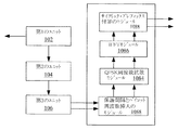
図1に示すように、従来技術におけるEBCMCSシステムのチャンネル構造は、チャンネル・コーディングに用いられる第1のユニット102と、チャンネル・スクランブリング、インターリービング及び重複に用いられる第2のユニット104と、直交振幅(QAM)の変調に用いられる第3のユニット106と、直交周波数分割多重(OFDM)の変調処理に用いられる第4のユニット108と、を含む。その中、第3のユニット106は16 QAM変調方式を採用する。第4のユニット108は、具体的に、保護間隔とパイロット周波数を挿入するモジュール1082と、QPSK周波数拡散モジュール1084と、逆高速フーリエ変換(IFFT)モジュール1086と、サイクリック・プレフィックス付加のモジュール1088と、を含む。
As shown in FIG. 1, the channel structure of the EBCMCS system in the prior art is orthogonal to a
相応的に、EBCMCSシステムに入力される信号の処理フローは以下の通りである:EBCMCSシステムに入力される信号は、先ず、第1のユニットによってチャンネル・コーディングされる。そのチャンネル・コーディングは1/5或は1/3のTurboコーディングである。次に、第2のユニットによってコーディング後の信号に対するチャンネル・スクランブリング、インターリービング、重複、スロッティングが行われる。また、第3のユニットによって16QAM変調方式にてスロッティング後の信号をI、Qの2ウェイに分ける。最後に、第4のユニットによって、入力されたI、Qの2ウェイの信号に対しそれぞれOFDM変調処理を行う。これで、処理フローを終了する。その中、EBCMCSシステムは、OFDM変調処理方式としては多搬送波変調を採用し、第4のユニットにおけるQPSK周波数拡散モジュールを採用していて、QPSK周波数拡散モジュールを含まずOFDM変調処理方式を採用する多搬送波変調システムとは異なり、多搬送波変調システムのOFDM変調処理後の信号ピーク対平均電力比(Peak-to-Average Power Rate、PAPRと略称する)を減少させる。 Correspondingly, the processing flow of the signal input to the EBCMCS system is as follows: The signal input to the EBCMCS system is first channel coded by the first unit. The channel coding is 1/5 or 1/3 Turbo coding. Next, channel scrambling, interleaving, duplication, and slotting are performed on the coded signal by the second unit. Further, the third unit divides the slotted signal into two ways of I and Q by the 16QAM modulation method. Finally, the fourth unit performs OFDM modulation processing on each of the input I and Q 2-way signals. This ends the processing flow. Among them, the EBCMCS system adopts multi-carrier modulation as the OFDM modulation processing method, adopts the QPSK frequency spreading module in the fourth unit, and does not include the QPSK frequency spreading module and adopts the OFDM modulation processing method. Unlike the carrier modulation system, the signal peak-to-average power rate (abbreviated as PAPR) after the OFDM modulation processing of the multi-carrier modulation system is reduced.
具体的に、通常、多搬送波変調システム中の信号PAPRは、以下のように獲得される。即ち、OFDM変調処理方式を採用する多搬送波変調システムにおいて、入力信号シーケンスの長さNのシーケンスが Specifically, the signal PAPR in a multi-carrier modulation system is usually obtained as follows. That is, in a multi-carrier modulation system that employs an OFDM modulation processing method, a sequence with a length N of an input signal sequence is
![]()
![]()
で(NはOFDMのサブ搬送波の量である)あるとする。入力信号X(n)の持続時間をTとすると、相応する各入力信号X(n)はOFDMの一つのサブ搬送波、即ち、{fn,n=0,1,…,N-1}に変調される。この場合、このN個のOFDMサブ搬送波は直交されるべきで、また、 (N is the amount of OFDM sub-carrier). If the duration of the input signal X (n) is T, each corresponding input signal X (n) is assigned to one OFDM sub-carrier, that is, {f n , n = 0, 1,..., N−1}. Modulated. In this case, the N OFDM subcarriers should be orthogonal, and
![]()
![]()
であるが、 In Although,
![]()
![]()
である。最後に、式(1)で、OFDM変調処理を行った後の信号を以下のように示す: It is. Finally, in Equation (1), the signal after OFDM modulation processing is shown as follows:

当該信号に対しナイクイスト(Nyquist)サンプリングを行い、式(2)で、獲得した分散信号を以下のように示すことができる: Nyquist sampling is performed on the signal, and with equation (2), the acquired distributed signal can be expressed as:
式(1)及び式(2)により、得られるピーク対平均電力比は以下のように示すことができる: From Equation (1) and Equation (2), the resulting peak-to-average power ratio can be expressed as follows:
単一搬送波変調システムに比べ、多搬送波変調システムは、OFDM変調処理方式を採用したため、その出力は複数のサブチャンネル信号が重畳されたものである。従って、複数のサブチャンネル信号の位相が一致する時、獲得される重畳信号の瞬間出力はサブチャンネル信号の平均出力より遥かに大きく、大きな信号PAPRを発生させるため、トランスミッター内のアンプリファイアの線形に対し極めて高い要求を出した。アンプリファイアの線形範囲がサブチャンネル信号の変化に満足できないと、サブチャンネル信号に歪みを発生させると共に、重畳信号の周波数スペクトルを変化させることによって、各サブチャンネル信号の間の直交性が破壊され、お互いに干渉して、上記多搬送波変調システムの性能が悪化することになる。 Compared to a single carrier modulation system, a multi-carrier modulation system employs an OFDM modulation processing method, so that its output is a superposition of a plurality of subchannel signals. Therefore, when the phases of multiple subchannel signals match, the instantaneous output of the superimposed signal acquired is much larger than the average output of the subchannel signal, and generates a large signal PAPR. They made very high demands. If the linear range of the amplifier is not satisfied with the change of the subchannel signal, the subchannel signal is distorted and the orthogonality between each subchannel signal is destroyed by changing the frequency spectrum of the superimposed signal, Interfering with each other will degrade the performance of the multi-carrier modulation system.
EBCMCSシステムもOFDM変調処理方式を採用する多搬送波変調システムであるため、QPSK周波数拡散モジュールを増加することによって多搬送波変調システムのOFDM変調処理後の信号のPAPRを低減したにもかかわらず、従来技術において、EBCMCSシステム中のQPSK周波数拡散モジュールを採用して行われるQPSK拡散周波数変調方法がQPSK周波数拡散モジュールに入力される信号に対し、1ウェイのQPSK拡散周波数変調を行うだけであるため、QPSK拡散周波数変調方法で信号のPAPRを低減する効果が顕著ではなく、また、多搬送波変調システム送信出力の線形範囲に対する要求も高いので、送信出力の設計に不利であり、送信出力のコストの増加にもなる。 Since the EBCMCS system is also a multi-carrier modulation system that employs the OFDM modulation processing method, the conventional technology is used despite the fact that the PAPR of the signal after the OFDM modulation processing of the multi-carrier modulation system is reduced by increasing the QPSK frequency spreading module QPSK spread frequency modulation method in the EBCMCS system adopting the QPSK frequency spread module only performs 1-way QPSK spread frequency modulation on the signal input to the QPSK frequency spread module. The effect of reducing the PAPR of the signal by the frequency modulation method is not remarkable, and the demand for the linear range of the multi-carrier modulation system transmission output is high, which is disadvantageous for the design of the transmission output and also increases the cost of the transmission output Become.
上記の一つ或は幾つかの問題に鑑み、本発明は信号のピーク対平均電力比を降下させる変調方法を提供する。 In view of one or several of the above problems, the present invention provides a modulation method that lowers the peak-to-average power ratio of a signal.
本発明の実施例に係る信号変調方法は、入力信号に対しチャンネル・コーディングを行って、チャンネル・コーディングを行った信号に対し、チャンネル・スクランブリング、インターリービング、重複、スロッティング処理における一つ又は複数の処理を行うステップと、処理後の信号を、信号ペアを構成するI、Qの二つの部分に分けるステップと、信号ペアを1ウェイ以上に分け、各ウェイの信号に対しそれぞれ異なる周波数拡散シーケンスを採用し4位相偏移変調周波数拡散(QPSK Spreading)を行うと共に、直交変調を行って、各ウェイの直交変調を行った信号のピーク対平均電力比を獲得するステップと、ピーク対平均電力比の最小の1ウェイ信号を出力信号として出力するステップとを含む。 In the signal modulation method according to the embodiment of the present invention, channel coding is performed on an input signal, and one of channel scrambling, interleaving, duplication, and slotting processing is performed on the channel-coded signal. A step of performing multiple processing, a step of dividing the processed signal into two parts of I and Q constituting the signal pair, and dividing the signal pair into one or more ways, and different frequency spreads for the signals of each way A sequence is used to perform quadrature phase shift keying (QPSK Spreading) and quadrature modulation to obtain the peak-to-average power ratio of the quadrature modulation of each way, and peak-to-average power Outputting a 1-way signal having a minimum ratio as an output signal.
そして、以下の式で周波数拡散シーケンスを生成する。即ち、h(D)=D17+D14+1。中には、信号ペアをMウェイに分け、また、周波数拡散シーケンスがs[k]、k=0,…,8NFFT[i]-1である場合、それぞれMウェイ信号に用いられる周波数拡散シーケンスは Then, a frequency spreading sequence is generated by the following equation. That is, h (D) = D 17 + D 14 +1. In some cases, the signal pair is divided into M-way, and when the frequency spread sequence is s [k], k = 0, ..., 8N FFT [i] -1, the frequency spread sequence used for each M-way signal Is
である。 It is.
そして、信号ペアが、 And the signal pair is
![]()
![]()
である場合、信号ペア中のI部分に採用される4位相偏移変調周波数拡散(QPSK Spreading)方式は、 , The 4-phase shift keying frequency spreading (QPSK Spreading) method adopted for the I part of the signal pair is
![]()
![]()
であり、信号ペアの中のQ部分に採用される4位相偏移変調周波数拡散(QPSK Spreading)方式は、 The four-phase shift keying frequency spreading (QPSK Spreading) method adopted for the Q part of the signal pair is
![]()
![]()
である。 It is.
そして、4位相偏移変調周波数拡散(QPSK Spreading)が行われた信号ペアのI部分は、 And the I part of the signal pair that has undergone four-phase shift keying frequency spreading (QPSK Spreading)
![]()
![]()
であり、4位相偏移変調周波数拡散(QPSK Spreading)が行われた信号ペアのQ部分は、 And the Q portion of the signal pair that has undergone four-phase shift keying frequency spreading (QPSK Spreading)
![]()
![]()
である。その中、4位相偏移変調周波数拡散(QPSK Spreading)が行われた信号ペアを複数形式にて以下のように示す。 It is. Among them, signal pairs subjected to four-phase shift keying frequency spreading (QPSK Spreading) are shown in a plurality of formats as follows.
![]()
![]()
そして、 And
という方式にて4位相偏移変調周波数拡散(QPSK Spreading)が行われた信号ペアに対し直交変調を行う。その中、 In this way, quadrature modulation is performed on a signal pair that has undergone four-phase shift keying (QPSK Spreading). Among them,
である。 It is.
そして、 And
という方式にて直交変調後の信号ペアのピーク対平均電力比を獲得する。その中、x(t)は直交変調が行われた信号ペアを示す。選択的に、 In this manner, the peak-to-average power ratio of the signal pair after quadrature modulation is obtained. Among them, x (t) indicates a signal pair subjected to quadrature modulation. Selectively,
![]()
![]()
という方式にて直交変調後の信号ペアのピーク対平均電力比を獲得する。また、 In this manner, the peak-to-average power ratio of the signal pair after quadrature modulation is obtained. Also,
という方式にて最小のピーク対平均電力比を獲得する。その中、x(t)は直交変調を行った信号ペアを示す。 To obtain the minimum peak-to-average power ratio. Among them, x (t) represents a signal pair subjected to quadrature modulation.
本発明において、QPSK周波数拡散モジュールに入力される信号を1ウェイ以上に分け、また各ウェイの信号に対しそれぞれQPSK拡散周波数変調を行い、また、QPSK拡散周波数変調を行う時、各ウェイの信号に対しそれぞれ異なる周波数拡散シーケンスを採用し変調を行う。本発明は1ウェイ以上の各ウェイの信号に対しそれぞれQPSK拡散周波数変調を行い、また、各ウェイの信号に対しそれぞれ異なる周波数拡散シーケンスを採用するため、異なる信号PAPRを獲得することができ、更に、獲得した全ての信号のPAPRにおける最小のPAPRを選択することができる。従って、信号PAPRを著しく低減でき、且つ、送信出力の設計に有利であると共に、送信出力のコストを低下させることが可能である。 In the present invention, the signal input to the QPSK frequency spread module is divided into one or more ways, and each way signal is subjected to QPSK spread frequency modulation. When performing QPSK spread frequency modulation, On the other hand, modulation is performed using different frequency spread sequences. The present invention performs QPSK spread frequency modulation for each way signal of 1 way or more, and adopts a different frequency spread sequence for each way signal, so that different signal PAPR can be obtained. , The smallest PAPR in the PAPR of all acquired signals can be selected. Therefore, the signal PAPR can be significantly reduced, and it is advantageous for the design of the transmission output, and the cost of the transmission output can be reduced.
ここで説明する図面は本発明の理解を深めるためのもので、本出願の一部を構成し、本出願に示す実施例及びその説明は本発明を解釈するもので、本発明を不当に限定するものではない。
本発明の核心思想は、QPSK周波数拡散モジュールに入力される信号をMウェイに分け、また、Mウェイの各ウェイの信号に対しそれぞれQPSK拡散周波数変調を行い、且つ、QPSK拡散周波数変調を行う時、各ウェイの信号に対しそれぞれ異なる周波数拡散シーケンスを採用する、ということである。本発明はMウェイの各ウェイの信号に対しそれぞれQPSK拡散周波数変調を行い、且つ、各ウェイの信号に対しそれぞれ異なる周波数拡散シーケンスを採用するため、異なる信号PAPRを得ることができ、更に、得られた全ての信号PAPRの中の最も小さい信号PAPRを選択することができる。 The core idea of the present invention is that the signal input to the QPSK frequency spread module is divided into M ways, and each way signal of the M way is subjected to QPSK spread frequency modulation and QPSK spread frequency modulation is performed. In other words, different frequency spread sequences are adopted for the signals of each way. The present invention performs QPSK spread frequency modulation on each way signal of the M way and adopts a different frequency spread sequence for each way signal, so that different signal PAPR can be obtained. It is possible to select the smallest signal PAPR among all the received signals PAPR.
以下、図面を参照して本発明の具体的な実施形態を詳しく説明する。 Hereinafter, specific embodiments of the present invention will be described in detail with reference to the drawings.
本発明の実施例の信号変調方法によると、チャンネル構造は図1に示すEBCMCSシステムのチャンネル構造に基づくが、主な区別としては、QPSK周波数拡散モジュールに対し採用するQPSK拡散周波数変調方法を変更したことである。本発明の実施例による信号変調方法は以下のステップを含む:
ステップ1:チャンネル・コーディングに用いられる第1のユニットが入力された信号に対しチャンネル・コーディングを行う。その中、チャンネル・コーディングは1/5或は1/3のTurboコーディングである。
According to the signal modulation method of the embodiment of the present invention, the channel structure is based on the channel structure of the EBCMCS system shown in FIG. 1, but the main difference is that the QPSK spread frequency modulation method adopted for the QPSK frequency spread module is changed. That is. A signal modulation method according to an embodiment of the present invention includes the following steps:
Step 1: Channel coding is performed on the input signal of the first unit used for channel coding. Among them, channel coding is 1/5 or 1/3 Turbo coding.
ステップ2:第1のユニットに接続され、チャンネル・スクランブリング、インターリービング及び重複に用いられる第2のユニットはチャンネル・コーディングを行った後に得られた信号に対し、チャンネル・スクランブリング、インターリービング、重複とスロッティングを行う。 Step 2: Connected to the first unit and used for channel scrambling, interleaving and duplication, the second unit uses the channel scrambling, interleaving, Duplicate and slotting.
ステップ3:第2のユニットに接続され、QAM変調に用いられる第3のユニットはスロッティング後の信号をI、Qの2ウェイの信号に分ける。当該2ウェイの信号はペアである;その中、第3のユニットは16QAM変調方式を採用しQAM変調を行う。 Step 3: The third unit connected to the second unit and used for QAM modulation divides the slotted signal into I and Q two-way signals. The two-way signals are a pair; among them, the third unit employs a 16QAM modulation scheme and performs QAM modulation.
ステップ4:第3のユニットに接続され、OFDM変調処理に用いられる第4のユニットは、得られたI、Q信号ペアを1ウェイ以上に分け、また、各ウェイの信号に対しそれぞれ異なる周波数拡散シーケンスを採用しQPSK拡散周波数変調を行って、全ての信号PAPRを得た後、出力信号として、その中の最も小さい信号QPSKを選択する。 Step 4: The fourth unit connected to the third unit and used for the OFDM modulation process divides the obtained I and Q signal pairs into one or more ways, and each frequency signal is spread differently. After the sequence is adopted and QPSK spread frequency modulation is performed to obtain all the signals PAPR, the smallest signal QPSK is selected as an output signal.
図2に示すように、ステップ4は以下のステップを含む:
S202:第4のユニットの中の保護間隔とパイロット周波数を挿入するモジュールは受信したI、Q信号ペアを接続されたQPSK周波数拡散モジュールに出力する。
As shown in FIG. 2,
S202: The module for inserting the protection interval and pilot frequency in the fourth unit outputs the received I and Q signal pair to the connected QPSK frequency spreading module.
S204:QPSK周波数拡散モジュールは受信したI、Q信号ペアをMウェイに分け、各ウェイの信号に対しそれぞれ異なる周波数拡散シーケンスを採用しQPSK拡散周波数変調を行い、また、QPSK拡散周波数変調を行った各ウェイのI、Q信号を接続されたIFFTモジュールに出力する。 S204: The QPSK frequency spreading module divides the received I and Q signal pairs into M ways, adopts different frequency spreading sequences for each way signal, performs QPSK spreading frequency modulation, and performs QPSK spreading frequency modulation Output the I and Q signals of each way to the connected IFFT module.
その中、EBCMCS協議により、ステップS204に採用される周波数拡散シーケンスは式(4)に従って生成できる: Among them, by EBCMCS consultation, the frequency spreading sequence adopted in step S204 can be generated according to equation (4):
![]()
![]()
式(4)は周波数拡散シーケンス多項式であり、最長線形フィードバック・シフト・レジスタシーケンスとも呼ばれ、mシーケンスである。図3はEBCMCS協議によるもので、ただ周波数拡散シーケンス生成方式を概略に示す図で式(4)を完全に示していない。 Equation (4) is a frequency spread sequence polynomial, also called the longest linear feedback shift register sequence, and is an m sequence. Fig. 3 is based on the EBCMCS discussion, and is a diagram that schematically shows the spread spectrum sequence generation method and does not completely show equation (4).
例えば、レジスタの初期値が[1c9c8c7c6c5c4c3c2c1c0x5x4x3x2x1x0]である場合、図3に示すように、c9c8c7c6c5c4c3c2c1c0の10ビット(bit)は周波数拡散因子(FDSSeed、Frequency domain spreading seed)によって確定され、x5x4x3x2x1x0の6ビット(bit)はシステム時間によって確定される。式(4)に従って周波数拡散シーケンスを生成し、また、生成した周波数拡散シーケンスをマッピングする必要がある。具体的なマッピング方式は、電気信号が0であるビット(bit)を+2(−1/2)にマッピングし、電気信号が1であるビット(bit)を−2(−1/2)にマッピングすることである。その中、データの同期を保証するために、各伝送の物理層パッケージの開始スロットでは、レジスタの中の数値を初期化する必要がある。 For example, if the initial value of the register is [1c 9 c 8 c 7 c 6 c 5 c 4 c 3 c 2 c 1 c 0 x 5 x 4 x 3 x 2 x 1 x 0], as shown in FIG. 3 10 bits of c 9 c 8 c 7 c 6 c 5 c 4 c 3 c 2 c 1 c 0 are determined by the frequency spreading factor (FDSSeed, Frequency domain spreading seed), and x 5 x 4 x 3 The 6 bits of x 2 x 1 x 0 are determined by the system time. It is necessary to generate a frequency spreading sequence according to Equation (4) and map the generated frequency spreading sequence. A specific mapping method is to map a bit (bit) where the electric signal is 0 to +2 (−1/2) and a bit (bit) where the electric signal is 1 to −2 (−1/2) . Is mapping. Among them, in order to guarantee data synchronization, the numerical value in the register needs to be initialized at the start slot of the physical layer package of each transmission.
相応的に、周波数拡散シーケンスがs[k]で、且つ、k=0,…,8NFFT[i]-1である場合、Mウェイの中の各ウェイの信号に対し採用する異なる周波数拡散シーケンスの詳細は以下の通りである: Correspondingly, if the frequency spread sequence is s [k] and k = 0, ..., 8N FFT [i] -1, different frequency spread sequences to be adopted for the signals of each way in the M way The details are as follows:
その中、NFFT[i]はEBCMCS協議によって規定される。当該パラメータによってIFFTモジュールの直交変調時に採用する変換指数が規定される。 Among them, N FFT [i] is defined by EBCMCS consultation. This parameter defines the conversion index to be used for IFFT module quadrature modulation.
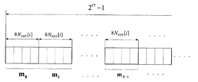
その中、周波数拡散シーケンスの中に採用される第一ウェイs0の周波数拡散シーケンスの具体的な獲得方法は図4の通りで、その使用される周波数拡散シーケンスはEBCMCS協議に規定されたものと同様で、要するに、QPSK周波数拡散に参与できる周波数拡散シーケンスである。即ち、式(4)に従って生成するmシーケンスの長さが217−1であり、且つ、各物理層のパッケージはEBCMCS協議に従って、若干のスロット(slot)、例えば、2つのスロット(slot)に分けられ、且つ、各スロット(slot)には2048のチップがある。後方互換の問題を考慮して、各スロット(slot)が保存できるデータ数は1600チップである。一つのスロット(slot)の中でQPSK周波数拡散に参与できる周波数拡散シーケンスのチップ数は1600個であるべきが、OFDMにサイクリック・プレフィックスを付加する必要があるため、EBCMCS協議により、実際に各スロット(slot)の中でQPSK周波数拡散を行う周波数拡散シーケンスのチップ数は4×NFFT[i]である。周波数拡散シーケンスのチップ数の総数が1600であるため、NFFT[i]は400以下でなければならなく、普通、数値は320、360、384とする。 Among them, the specific acquisition method of the frequency spread sequence of the first way s 0 adopted in the frequency spread sequence is as shown in FIG. 4, and the frequency spread sequence used is that specified in the EBCMCS consultation. Similarly, in short, it is a frequency spreading sequence that can participate in QPSK frequency spreading. That is, the length of the m-sequence generated according to the equation (4) is 2 17 −1, and the package of each physical layer is divided into some slots (for example, two slots) according to the EBCMCS consultation. There are 2048 chips in each slot. In consideration of backward compatibility, the number of data that each slot can store is 1600 chips. The number of chips in the frequency spreading sequence that can participate in QPSK frequency spreading in one slot (slot) should be 1600, but since it is necessary to add a cyclic prefix to OFDM, The number of chips of a frequency spreading sequence for performing QPSK frequency spreading in a slot is 4 × N FFT [i]. Since the total number of chips in the frequency spread sequence is 1600, N FFT [i] must be less than or equal to 400, and usually the numbers are 320, 360, and 384.
本発明の実施例の信号変調方法によりQPSK周波数拡散を行う時、式(6)と式(7)に示した拡散周波数変調方式でQPSK周波数拡散を行う。式(6)と式(7)によると、IウェイとQウェイに対し異なる周波数拡散シーケンスを使用する必要があって、式(6)と式(7)の中に使用されたのはs[2k]とs[2k+1]である。各スロット(slot)の中でQPSK周波数拡散を行う時、採用する周波数拡散シーケンスのチップ数は8×NFFT[i]個である。相応的に、N×NFFT[i]個の周波数拡散シーケンスの中から、最小の信号PAPRである周波数拡散シーケンスを選択し伝送を行い、選択された周波数拡散シーケンスの番号を受信先に伝送する。 When QPSK frequency spreading is performed by the signal modulation method according to the embodiment of the present invention, QPSK frequency spreading is performed by the spreading frequency modulation method shown in Equation (6) and Equation (7). According to Equation (6) and Equation (7), it is necessary to use different frequency spreading sequences for I-way and Q-way, and the one used in Equation (6) and Equation (7) is s [ 2k] and s [2k + 1]. When performing QPSK frequency spreading in each slot, the number of chips of the frequency spreading sequence adopted is 8 × N FFT [i]. Correspondingly, the frequency spread sequence which is the minimum signal PAPR is selected from N × N FFT [i] frequency spread sequences and transmitted, and the number of the selected frequency spread sequence is transmitted to the receiver. .
S206:IFFTモジュールはQPSK拡散周波数変調された各ウェイのI、Q信号を獲得して、獲得した各ウェイのI、Q信号に対しそれぞれ直交変調を行って、MウェイのI、Q信号の信号PAPRを獲得した後、信号PAPRが最小である1ウェイの信号を出力信号として選択し、接続されたサイクリック・プレフィックス付加のモジュールに出力する。 S206: IFFT module acquires I and Q signals of each way that are QPSK spread frequency modulated, performs quadrature modulation on the acquired I and Q signals of each way, and signals of M way I and Q signals After acquiring the PAPR, the one-way signal having the smallest signal PAPR is selected as an output signal and output to the connected module with the cyclic prefix.
例えば、ステップS202の中で受信するI、Q信号ペアがC"I/Q[i][k]で、且つ、 For example, the I and Q signal pair received in step S202 is C " I / Q [i] [k], and
![]()
![]()
である場合、本発明の実施例によるQPSK拡散周波数変調方法は以下のステップを含む:
S202:第4のユニットにおける保護間隔とパイロット周波数を挿入するモジュールは、受信したI、Q信号ペアであるC"I/Q[i][k]を接続されたQPSK周波数拡散モジュールに出力する。
The QPSK spread frequency modulation method according to an embodiment of the present invention includes the following steps:
S202: The module for inserting the protection interval and the pilot frequency in the fourth unit outputs the received I, Q signal pair C " I / Q [i] [k] to the connected QPSK frequency spreading module.
S204:QPSK周波数拡散モジュールは受信した信号をMウェイに分け、各ウェイの信号に対しそれぞれ異なる周波数拡散シーケンスを採用しQPSK拡散周波数変調を行う。 S204: The QPSK frequency spreading module divides the received signal into M ways, and adopts a different frequency spreading sequence for each way signal to perform QPSK spreading frequency modulation.
この時、各ウェイの信号に対しQPSK拡散周波数変調を行って、獲得したQPSK拡散周波数変調後のI、Q信号ペアは、uI/Q[i][k]で、且つ、i=0,…,Nspp-1、k=0,…,4NFFT[i]-1であって、NFFT[i]、NsppはEBCMCS協議によって規定される。そうすると、採用したQPSK拡散周波数変調方式は具体的に以下の通りである: At this time, QPSK spread frequency modulation is performed on the signal of each way, and the obtained I and Q signal pair after QPSK spread frequency modulation is u I / Q [i] [k] and i = 0, …, N spp −1, k = 0,…, 4N FFT [i] −1, where N FFT [i] and N spp are defined by the EBCMCS consultation. Then, the adopted QPSK spread frequency modulation scheme is specifically as follows:
![]()
![]()
![]()
![]()
式(6)及び式(7)に従って、Mウェイの各ウェイの信号に対しそれぞれQPSK拡散周波数変調を行い、QPSK拡散周波数変調後の各ウェイの信号を接続されたIFFTモジュールに出力する。 According to Equation (6) and Equation (7), QPSK spread frequency modulation is performed on each way signal of the M way, and the signal of each way after QPSK spread frequency modulation is output to the connected IFFT module.
その中、Mウェイの中の各ウェイの信号に対し、式(5)に従って獲得した異なる周波数拡散シーケンスを採用する時、相応的に、Mウェイの中の各ウェイの信号に対し、式(6)及び式(7)に従ってQPSK拡散周波数変調を行った後、QPSK拡散周波数変調後の各ウェイのI、Q信号を獲得する。その詳細は以下の通りである: Among them, when adopting a different frequency spread sequence obtained according to Equation (5) for each way signal in the M way, correspondingly, for each way signal in the M way, Equation (6 ) And Equation (7), and after performing QPSK spread frequency modulation, I and Q signals of each way after QPSK spread frequency modulation are acquired. The details are as follows:
![]()
![]()
その中、QPSK拡散周波数変調を行った各ウェイのI、Q信号を複数形式で以下のように示すことができる。 Among them, the I and Q signals of each way subjected to QPSK spread frequency modulation can be shown in a plurality of formats as follows.
![]()
![]()
S206:IFFTモジュールはQPSK拡散周波数変調後の各ウェイのI、Q信号を獲得し、獲得した各ウェイのI、Q信号に対しそれぞれ直交変調を行う。その中、獲得した直交変調後の信号がvm[i][k']である場合、採用する直交変調方式の詳細は以下の通りである。 S206: The IFFT module acquires I and Q signals of each way after QPSK spread frequency modulation, and performs orthogonal modulation on the acquired I and Q signals of each way. Among them, when the acquired signal after orthogonal modulation is v m [i] [k ′], details of the orthogonal modulation method to be employed are as follows.
ここでは、x(t)で直交変調後の信号を示す。相応的に、式(3)に従って各ウェイの直交変調後の信号PAPRを演算する。信号PAPRは、直交変調後の全ての信号において、信号の最大出力と信号の平均出力の比率である。 Here, a signal after quadrature modulation is indicated by x (t). Correspondingly, the signal PAPR after quadrature modulation of each way is calculated according to equation (3). The signal PAPR is the ratio of the maximum signal output to the average signal output for all signals after quadrature modulation.
最後に、全ての信号PAPRを獲得した後、最小の信号PAPRを出力信号とし、接続されたサイクリック・プレフィックス付加のモジュールに出力する。 Finally, after all the signals PAPR are acquired, the minimum signal PAPR is output as an output signal and output to the connected cyclic prefix added module.
その中、QPSK拡散周波数変調方式において、信号に対する乗算操作は、信号の位相に対し干渉を行ったことに相当し、信号の平均出力に影響を与えないため、ステップS206における式(3)に従う各ウェイの直交変調後の信号PAPRの演算は、更に、 Among them, in the QPSK spread frequency modulation system, the multiplication operation on the signal is equivalent to performing interference on the phase of the signal and does not affect the average output of the signal. The calculation of the signal PAPR after the quadrature modulation of the way is
![]()
![]()
に簡素化することができる。即ち、信号PAPRの演算の式を、直交変調後の全ての信号の最大出力の演算に簡素化することができる。その中、x(t)で直交変調後の信号を示す時、信号PAPRを選択する式の詳細は以下の通りである。 Can be simplified. That is, the equation for calculating the signal PAPR can be simplified to calculate the maximum output of all signals after quadrature modulation. Among them, when the signal after quadrature modulation is indicated by x (t), the details of the equation for selecting the signal PAPR are as follows.
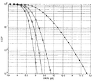
選択される周波数拡散シーケンスを受信先で分かる方法がないため、変調を行うように、選択した情報をサイドバンド情報として受信先に伝送する必要があるので、伝送される信号のデータ量はlog2(M)ビット(bit)でなければならない。図5は、本発明実施例による方法と従来技術におけるQPSK拡散周波数変調方法で信号PAPRを降下する効果を対比して示す図である。図5において、横軸は信号PAPRで、縦軸は信号PAPRの相補累積分布関数(complementary cumulative density function、CCDFと略称する)に対応する関数値である。図5に示す効果図は相補累積分布関数の関数分布を表す曲線図である。当該曲線図より、異なる周波数拡散方式で獲得した信号PAPRの対照を直観的に得られる。図5には本発明の実施例のQPSK周波数拡散方式を採用し、且つ、M=4、M=8とM=16の場合、獲得した信号PAPRに対応する相補累積分布関数の関数分布の曲線図が含まれている。 Since there is no way to know the selected spread spectrum sequence at the receiver, it is necessary to transmit the selected information as sideband information to the receiver so as to perform modulation, so the data amount of the transmitted signal is log 2 (M) Must be a bit. FIG. 5 is a diagram comparing the effect of lowering the signal PAPR with the method according to the embodiment of the present invention and the conventional QPSK spread frequency modulation method. In FIG. 5, the horizontal axis is the signal PAPR, and the vertical axis is the function value corresponding to the complementary cumulative density function (abbreviated as CCDF) of the signal PAPR. The effect diagram shown in FIG. 5 is a curve diagram showing the function distribution of the complementary cumulative distribution function. From the curve diagram, it is possible to intuitively obtain a contrast of the signal PAPR acquired by different frequency spreading methods. FIG. 5 shows the function distribution curve of the complementary cumulative distribution function corresponding to the acquired signal PAPR when the QPSK frequency spreading method of the embodiment of the present invention is adopted and M = 4, M = 8 and M = 16. Illustration is included.
図5において、「米」の記号で従来技術におけるQPSK周波数拡散方式でQPSK周波数拡散を行った後に獲得した信号PAPRを示す。それ以外の記号は全て本発明の実施例におけるQPSK周波数拡散方式でQPSK周波数拡散を行った後に獲得した信号PAPRを示す。その中、円形記号で標記した曲線がM=16の時、正方形記号で標記した曲線がM=8の時、菱形記号で標記した曲線がM=4の時のQPSK周波数拡散後に獲得した信号PAPRを示す。 In FIG. 5, the symbol “rice” indicates a signal PAPR obtained after QPSK frequency spreading by the QPSK frequency spreading method in the prior art. All other symbols indicate the signal PAPR obtained after QPSK frequency spreading by the QPSK frequency spreading method in the embodiment of the present invention. Among them, the signal PAPR obtained after QPSK frequency spreading when the curve marked with a circular symbol is M = 16, the curve marked with a square symbol is M = 8, and the curve marked with a diamond symbol is M = 4 Indicates.
図5により直観的に分かるように、M=4、M=8とM=16の場合、本発明の実施例による方法は従来技術中の方法に比べ、より良く信号PAPRを抑制でき、信号PAPRを著しく低減する。 As can be seen intuitively from FIG. 5, when M = 4, M = 8 and M = 16, the method according to the embodiment of the present invention can suppress the signal PAPR better than the method in the prior art, and the signal PAPR Is significantly reduced.
前記内容はただ本発明の好ましい実施例で、本発明を不当に限定するものではない。当業者にとって、本発明の主旨を逸脱しない範囲内で種々変更して実施することが可能である。本発明の目的と原則の範囲内に入っている限り、行った如何なる修正、同等の引き換え、または改良などが、全て本発明の保護範囲に含まれるべきである。 The foregoing is merely a preferred embodiment of the present invention and does not unduly limit the present invention. For those skilled in the art, various modifications can be made without departing from the spirit of the present invention. Any modification, equivalent replacement, or improvement made should be included in the protection scope of the present invention as long as it is within the scope of the object and principle of the present invention.
Claims (7)
処理後の信号を、一つの信号ペアを構成するI、Qの二部分に分けるステップと、
前記信号ペアを1ウェイ以上に分け、各ウェイの信号に対しそれぞれ異なる周波数拡散シーケンスを採用し4位相偏移変調周波数拡散(QPSK Spreading)を行うと共に、直交変調を行って、直交変調が行われた各ウェイの信号のピーク対平均電力比を獲得するステップと、
ピーク対平均電力比が最小の1ウェイ信号を出力信号として出力するステップと、を含み、
前記周波数拡散シーケンスは、式h(D)=D 17 +D 14 +1に従って生成され、
前記信号ペアがMウェイに分けられ、且つ、前記周波数拡散シーケンスがs[k]、k=0,…,8NFFT[i]-1である時、前記Mウェイ信号のそれぞれに用いられる周波数拡散シーケンスは
Dividing the processed signal into two parts, I and Q, constituting one signal pair;
The signal pair is divided into one or more ways, and different frequency spreading sequences are used for the signals of each way to perform quadrature phase shift keying (QPSK Spreading) and quadrature modulation to perform quadrature modulation. Obtaining a peak-to-average power ratio for each way signal;
A step of peak-to-average power ratio to output a minimum of 1 way signal as an output signal, only including,
The frequency spreading sequence is generated according to the equation h (D) = D 17 + D 14 +1,
When the signal pair is divided into M-way and the frequency spread sequence is s [k], k = 0,..., 8NFFT [i] -1, the frequency spread sequence used for each of the M-way signals Is
前記信号ペアが、
前記信号ペアにおけるI部分に採用される4位相偏移変調周波数拡散(QPSK Spreading)方式は、
The signal pair is
The four phase shift keying frequency spreading (QPSK Spreading) method employed for the I part of the signal pair is:
4位相偏移変調周波数拡散(QPSK Spreading)が行われた信号ペアのI部分は、
The I part of a signal pair that has undergone four phase shift keying frequency spreading (QPSK Spreading)
前記4位相偏移変調周波数拡散(QPSK Spreading)が行われた信号ペアを複数形式で、
The signal pair subjected to the four phase shift keying frequency spreading (QPSK Spreading) in a plurality of formats,
前記4位相偏移変調周波数拡散(QPSK Spreading)が行われた信号ペアに対し、
For the signal pair subjected to the four phase shift keying frequency spreading (QPSK Spreading),
直交変調が行われた信号ペアのピーク対平均電力比を、
The peak-to-average power ratio of a signal pair that has undergone quadrature modulation,
Applications Claiming Priority (3)
| Application Number | Priority Date | Filing Date | Title |
|---|---|---|---|
| CN2007101085098A CN101136888B (en) | 2007-05-18 | 2007-05-18 | Modulation method to reduce signal peak-to-average power ratio |
| CN200710108509.8 | 2007-05-18 | ||
| PCT/CN2007/003263 WO2008141498A1 (en) | 2007-05-18 | 2007-11-19 | Signal modulation method |
Publications (2)
| Publication Number | Publication Date |
|---|---|
| JP2010527546A JP2010527546A (en) | 2010-08-12 |
| JP5259697B2 true JP5259697B2 (en) | 2013-08-07 |
Family
ID=39160722
Family Applications (1)
| Application Number | Title | Priority Date | Filing Date |
|---|---|---|---|
| JP2010507778A Expired - Fee Related JP5259697B2 (en) | 2007-05-18 | 2007-11-19 | Signal modulation method |
Country Status (5)
| Country | Link |
|---|---|
| US (1) | US8416837B2 (en) |
| JP (1) | JP5259697B2 (en) |
| CN (1) | CN101136888B (en) |
| CA (1) | CA2687293C (en) |
| WO (1) | WO2008141498A1 (en) |
Families Citing this family (21)
| Publication number | Priority date | Publication date | Assignee | Title |
|---|---|---|---|---|
| US8670390B2 (en) | 2000-11-22 | 2014-03-11 | Genghiscomm Holdings, LLC | Cooperative beam-forming in wireless networks |
| US10931338B2 (en) | 2001-04-26 | 2021-02-23 | Genghiscomm Holdings, LLC | Coordinated multipoint systems |
| US9819449B2 (en) | 2002-05-14 | 2017-11-14 | Genghiscomm Holdings, LLC | Cooperative subspace demultiplexing in content delivery networks |
| US10355720B2 (en) | 2001-04-26 | 2019-07-16 | Genghiscomm Holdings, LLC | Distributed software-defined radio |
| US10644916B1 (en) | 2002-05-14 | 2020-05-05 | Genghiscomm Holdings, LLC | Spreading and precoding in OFDM |
| US10142082B1 (en) | 2002-05-14 | 2018-11-27 | Genghiscomm Holdings, LLC | Pre-coding in OFDM |
| US9628231B2 (en) | 2002-05-14 | 2017-04-18 | Genghiscomm Holdings, LLC | Spreading and precoding in OFDM |
| US10200227B2 (en) | 2002-05-14 | 2019-02-05 | Genghiscomm Holdings, LLC | Pre-coding in multi-user MIMO |
| US11431386B1 (en) | 2004-08-02 | 2022-08-30 | Genghiscomm Holdings, LLC | Transmit pre-coding |
| US11184037B1 (en) | 2004-08-02 | 2021-11-23 | Genghiscomm Holdings, LLC | Demodulating and decoding carrier interferometry signals |
| US11552737B1 (en) | 2004-08-02 | 2023-01-10 | Genghiscomm Holdings, LLC | Cooperative MIMO |
| US12224860B1 (en) | 2014-01-30 | 2025-02-11 | Genghiscomm Holdings, LLC | Linear coding in decentralized networks |
| CN107949991B (en) | 2015-09-02 | 2020-10-27 | 华为技术有限公司 | A signal transmission or reception method and device |
| US10637705B1 (en) | 2017-05-25 | 2020-04-28 | Genghiscomm Holdings, LLC | Peak-to-average-power reduction for OFDM multiple access |
| US10243773B1 (en) | 2017-06-30 | 2019-03-26 | Genghiscomm Holdings, LLC | Efficient peak-to-average-power reduction for OFDM and MIMO-OFDM |
| US11343823B2 (en) | 2020-08-16 | 2022-05-24 | Tybalt, Llc | Orthogonal multiple access and non-orthogonal multiple access |
| US12206535B1 (en) | 2018-06-17 | 2025-01-21 | Tybalt, Llc | Artificial neural networks in wireless communication systems |
| US11917604B2 (en) | 2019-01-25 | 2024-02-27 | Tybalt, Llc | Orthogonal multiple access and non-orthogonal multiple access |
| EP3915236A4 (en) | 2019-01-25 | 2023-05-24 | Genghiscomm Holdings, LLC | ORTHOGONAL MULTIPLE ACCESS, AND NON-ORTHOGONAL MULTIPLE ACCESS |
| WO2020242898A1 (en) | 2019-05-26 | 2020-12-03 | Genghiscomm Holdings, LLC | Non-orthogonal multiple access |
| CN115276892A (en) * | 2021-04-30 | 2022-11-01 | 上海华为技术有限公司 | A signal generation method, a signal processing method and related equipment |
Family Cites Families (13)
| Publication number | Priority date | Publication date | Assignee | Title |
|---|---|---|---|---|
| KR100269593B1 (en) * | 1997-12-02 | 2000-10-16 | 정선종 | Orthogonal complex spreading based modulation method for multichannel transmission |
| JPH11215091A (en) | 1998-01-22 | 1999-08-06 | Toshiba Corp | OFDM signal transmission method and OFDM signal transmission apparatus |
| KR20000073917A (en) | 1999-05-15 | 2000-12-05 | 윤종용 | Apparatus and method for generating sync word pattern and transmitting and receiving said sync word in cdma communication system |
| KR100754721B1 (en) * | 2002-04-26 | 2007-09-03 | 삼성전자주식회사 | Multiplexed Data Transceiver and Method in Orthogonal Frequency Division Multiplexed Communication System |
| KR20040005175A (en) * | 2002-07-08 | 2004-01-16 | 삼성전자주식회사 | Apparatus and method for transmitting and receiving side information of selective mapping in orthogonal frequency division multiplexing communication system |
| KR100933115B1 (en) * | 2003-09-09 | 2009-12-21 | 삼성전자주식회사 | Apparatus and method for reducing peak to average power ratio in a orthogonal frequency division multiplexing communication system |
| JP4077398B2 (en) | 2003-11-25 | 2008-04-16 | 日本電信電話株式会社 | Wireless communication system, wireless communication method, and transmitter |
| US7362790B2 (en) * | 2004-05-07 | 2008-04-22 | Samsung Electronics Co., Ltd. | Apparatus and method for generating pseudo-replica signals in a CDMA communication system |
| JP4153906B2 (en) * | 2004-07-09 | 2008-09-24 | 株式会社東芝 | Communication apparatus, transmission method, and reception method |
| KR100666689B1 (en) * | 2004-09-24 | 2007-01-09 | 유흥균 | Real-time Peak-to-Average Power Reduction Method Using Phase Rotation and Selective Mapping Method and Data Transmission System Using the Same |
| CN100568867C (en) * | 2005-08-12 | 2009-12-09 | 中兴通讯股份有限公司 | A Method of Reducing Peak-to-Average Ratio in Multi-Carrier Modulation System |
| JP4637061B2 (en) * | 2006-06-28 | 2011-02-23 | 富士通株式会社 | Wireless transmission device and guard interval insertion method |
| WO2008060202A1 (en) * | 2006-11-13 | 2008-05-22 | Telefonaktiebolaget Lm Ericsson (Publ) | A method for limiting local bandwidth impairment using tone reservation |
-
2007
- 2007-05-18 CN CN2007101085098A patent/CN101136888B/en not_active Expired - Fee Related
- 2007-11-19 WO PCT/CN2007/003263 patent/WO2008141498A1/en not_active Ceased
- 2007-11-19 CA CA2687293A patent/CA2687293C/en not_active Expired - Fee Related
- 2007-11-19 US US12/600,254 patent/US8416837B2/en not_active Expired - Fee Related
- 2007-11-19 JP JP2010507778A patent/JP5259697B2/en not_active Expired - Fee Related
Also Published As
| Publication number | Publication date |
|---|---|
| CN101136888B (en) | 2011-09-21 |
| CA2687293C (en) | 2015-08-11 |
| CN101136888A (en) | 2008-03-05 |
| CA2687293A1 (en) | 2008-11-27 |
| WO2008141498A1 (en) | 2008-11-27 |
| JP2010527546A (en) | 2010-08-12 |
| US20100303126A1 (en) | 2010-12-02 |
| US8416837B2 (en) | 2013-04-09 |
Similar Documents
| Publication | Publication Date | Title |
|---|---|---|
| JP5259697B2 (en) | Signal modulation method | |
| US7376074B2 (en) | Apparatus and method for transmitting and receiving side information of a partial transmit sequence in an OFDM communication system | |
| CN107302512A (en) | System and method for control combination wireless signal | |
| CN1434588A (en) | Time-frequency union spreading method based on OFDM-CDMA for broadband radio communication system | |
| CN102299890B (en) | Multimedia broadcasting wireless signal anti-interference framing modulation method | |
| CN102263738B (en) | Anti-interference transmission method for digital broadcast wireless signal | |
| Manhas et al. | OFDM PAPR reduction using recurring SLM with cyclic and linear block codes schemes | |
| CN102271117B (en) | A framing modulation method for anti-jamming multimedia wireless broadcasting signal | |
| CN102307171A (en) | Anti-interference wireless multimedia broadcast signal framing modulation method | |
| CN103763249A (en) | Anti-interference wireless signal transmission method for digital broadcast | |
| CN102281239B (en) | Anti-interference multimedia mobile broadcast signal framing modulation method | |
| Takyu et al. | Orthogonal variable spreading factor code selection for peak power reduction in multi-rate OFCDM systems | |
| CN103763247A (en) | Anti-fading multi-media wireless radio signal framing modulation method | |
| Nassar et al. | Multi‐carrier platform for wireless communications. Part 2: OFDM and MC‐CDMA systems with high‐performance, high‐throughput via innovations in spreading | |
| CN103780539A (en) | Robust wireless multi-media radio signal framing modulation method | |
| CN103780553A (en) | Transmission method of anti-interference digital wireless broadcast signals | |
| CN103763290A (en) | Method for framing and modulating anti-interference wireless multimedia broadcast signals in single frequency network | |
| CN103763279A (en) | Anti-fading wireless multi-media radio signal framing modulation method | |
| CN103763283A (en) | Anti-fading digital mobile radio signal transmission method | |
| CN103780551A (en) | Transmission method of anti-fading digital wireless broadcasting signals | |
| CN103780543A (en) | Framing modulation method of anti-interference mobile multimedia broadcasting signals | |
| CN103763280A (en) | Anti-interference framing and modulating method for multimedia wireless radio signals | |
| CN103763273A (en) | Anti-interference framing modulation method for wireless signals of multimedia broadcast | |
| CN103763278A (en) | Transmission method for robust digital mobile broadcast signals | |
| CN103763257A (en) | Anti-interference transmission method for wireless digital radio signals |
Legal Events
| Date | Code | Title | Description |
|---|---|---|---|
| A621 | Written request for application examination |
Free format text: JAPANESE INTERMEDIATE CODE: A621 Effective date: 20101005 |
|
| A977 | Report on retrieval |
Free format text: JAPANESE INTERMEDIATE CODE: A971007 Effective date: 20120810 |
|
| A131 | Notification of reasons for refusal |
Free format text: JAPANESE INTERMEDIATE CODE: A131 Effective date: 20120821 |
|
| A521 | Request for written amendment filed |
Free format text: JAPANESE INTERMEDIATE CODE: A523 Effective date: 20121108 |
|
| RD02 | Notification of acceptance of power of attorney |
Free format text: JAPANESE INTERMEDIATE CODE: A7422 Effective date: 20121108 |
|
| TRDD | Decision of grant or rejection written | ||
| A01 | Written decision to grant a patent or to grant a registration (utility model) |
Free format text: JAPANESE INTERMEDIATE CODE: A01 Effective date: 20130402 |
|
| A61 | First payment of annual fees (during grant procedure) |
Free format text: JAPANESE INTERMEDIATE CODE: A61 Effective date: 20130424 |
|
| FPAY | Renewal fee payment (event date is renewal date of database) |
Free format text: PAYMENT UNTIL: 20160502 Year of fee payment: 3 |
|
| R150 | Certificate of patent or registration of utility model |
Free format text: JAPANESE INTERMEDIATE CODE: R150 |
|
| LAPS | Cancellation because of no payment of annual fees |