JP5259491B2 - Power cable connection device and method for assembling the same - Google Patents
Power cable connection device and method for assembling the same Download PDFInfo
- Publication number
- JP5259491B2 JP5259491B2 JP2009123885A JP2009123885A JP5259491B2 JP 5259491 B2 JP5259491 B2 JP 5259491B2 JP 2009123885 A JP2009123885 A JP 2009123885A JP 2009123885 A JP2009123885 A JP 2009123885A JP 5259491 B2 JP5259491 B2 JP 5259491B2
- Authority
- JP
- Japan
- Prior art keywords
- connection
- screw
- lock nut
- flange
- power cable
- Prior art date
- Legal status (The legal status is an assumption and is not a legal conclusion. Google has not performed a legal analysis and makes no representation as to the accuracy of the status listed.)
- Expired - Fee Related
Links
- 238000000034 method Methods 0.000 title claims description 13
- 238000003780 insertion Methods 0.000 claims description 25
- 230000037431 insertion Effects 0.000 claims description 25
- 239000004020 conductor Substances 0.000 claims description 12
- 230000000149 penetrating effect Effects 0.000 claims description 2
- 230000002093 peripheral effect Effects 0.000 description 19
- 230000006835 compression Effects 0.000 description 8
- 238000007906 compression Methods 0.000 description 8
- RYGMFSIKBFXOCR-UHFFFAOYSA-N Copper Chemical compound [Cu] RYGMFSIKBFXOCR-UHFFFAOYSA-N 0.000 description 4
- 229910052802 copper Inorganic materials 0.000 description 4
- 239000010949 copper Substances 0.000 description 4
- 229910045601 alloy Inorganic materials 0.000 description 3
- 239000000956 alloy Substances 0.000 description 3
- 238000009413 insulation Methods 0.000 description 3
- 238000004519 manufacturing process Methods 0.000 description 3
- 239000002184 metal Substances 0.000 description 3
- 229910052751 metal Inorganic materials 0.000 description 3
- 239000013013 elastic material Substances 0.000 description 2
- 229910000906 Bronze Inorganic materials 0.000 description 1
- 229910000881 Cu alloy Inorganic materials 0.000 description 1
- 229910000640 Fe alloy Inorganic materials 0.000 description 1
- OAICVXFJPJFONN-UHFFFAOYSA-N Phosphorus Chemical compound [P] OAICVXFJPJFONN-UHFFFAOYSA-N 0.000 description 1
- ATJFFYVFTNAWJD-UHFFFAOYSA-N Tin Chemical compound [Sn] ATJFFYVFTNAWJD-UHFFFAOYSA-N 0.000 description 1
- 230000005540 biological transmission Effects 0.000 description 1
- 239000010974 bronze Substances 0.000 description 1
- 238000010276 construction Methods 0.000 description 1
- KUNSUQLRTQLHQQ-UHFFFAOYSA-N copper tin Chemical compound [Cu].[Sn] KUNSUQLRTQLHQQ-UHFFFAOYSA-N 0.000 description 1
- 238000000605 extraction Methods 0.000 description 1
- 239000004033 plastic Substances 0.000 description 1
- 230000002265 prevention Effects 0.000 description 1
- 230000001105 regulatory effect Effects 0.000 description 1
Images


Landscapes
- Details Of Connecting Devices For Male And Female Coupling (AREA)
Description
この発明は、各種機械装置に電力を供給する為の電力ケーブルの端部同士を、電気的且つ機械的に接続する為の接続装置及びその組立方法の改良に関する。具体的には、外径寸法を小さく抑えられる構造で、接続作業を容易に行う事ができ、且つ、接続部の抵抗を低く抑える事ができ、しかも、接続部の機械強度を十分に確保できる電力ケーブル用接続装置及びその組立方法を実現するものである。 The present invention relates to an improvement in a connecting device for electrically and mechanically connecting ends of a power cable for supplying electric power to various mechanical devices, and an assembling method thereof. Specifically, the outer diameter can be kept small, the connection work can be easily performed, the resistance of the connection part can be kept low, and the mechanical strength of the connection part can be sufficiently secured. A power cable connecting device and an assembling method thereof are realized.
各種機械装置に電力を供給する為の電力ケーブルの端部同士は、銅系合金等の電気抵抗の低い金属により造った接続端子を備えた接続装置により接続する必要がある。電力ケーブルは、例えば工事等の進捗状況に応じて接続状態を変更する必要がある為、接続作業を容易に行える構造である必要がある。又、送電ロスを低く抑える為に接続部の電気抵抗を低く抑える必要がある事は勿論、前記電力ケーブルに引っ張り方向の力が加わった場合にも外れない様に、十分な機械的強度(特に引っ張り強度)を有する事が必要である。この様な要求を満たす電力ケーブル用接続装置として、例えば特許文献1に記載された構造が知られている。但しこの特許文献1に記載された構造は、電気抵抗を低く抑え、機械的強度を確保する面からは優れているが、接続端子の形状が特殊である為、製造コストが嵩む。又、接続装置全体としての外径寸法を、必ずしも小さく抑える事ができず、接続装置の小型・軽量化を図りにくい。尚、本発明を実施する場合に関連する技術を記載した刊行物として、例えば特許文献2がある。
The ends of the power cable for supplying power to various mechanical devices need to be connected by a connection device having a connection terminal made of a metal having a low electrical resistance such as a copper alloy. For example, the power cable needs to have a structure that allows easy connection work because the connection state needs to be changed in accordance with the progress of construction or the like. Moreover, in order to keep the power transmission loss low, it is necessary to keep the electrical resistance of the connection part low, and of course, sufficient mechanical strength (especially in order not to come off even when a force in the pulling direction is applied to the power cable) It is necessary to have tensile strength. As a power cable connecting device that satisfies such a requirement, for example, a structure described in Patent Document 1 is known. However, although the structure described in Patent Document 1 is excellent in terms of suppressing electric resistance and ensuring mechanical strength, the manufacturing cost increases because the shape of the connection terminal is special. In addition, the outer diameter of the connecting device as a whole cannot always be kept small, and it is difficult to reduce the size and weight of the connecting device. Note that, for example, there is
本発明は、上述の様な事情に鑑みて、特殊な形状を有する部品を使用せず、低コストで造る事ができる構造の実現を意図したものである。そして、外径寸法を小さく抑えられる構造で、接続作業を容易に行う事ができ、且つ、接続部の抵抗を低く抑える事ができ、しかも、接続部の機械強度を十分に確保できる電力ケーブル用接続装置及びその組立方法を実現するものである。 In view of the circumstances as described above, the present invention is intended to realize a structure that can be manufactured at low cost without using a part having a special shape. And with a structure that can keep the outer diameter dimension small, the connection work can be done easily, the resistance of the connection part can be kept low, and the mechanical strength of the connection part can be sufficiently secured. A connecting device and an assembling method thereof are realized.
本発明の電力ケーブル用接続装置及びその組立方法のうち、請求項1に記載した電力ケーブル用接続装置は、それぞれが、銅又は銅系合金等の電気抵抗の低い金属製である、第一の接続端子と、第二の接続端子と、接続筒と、ロックナットと、1対の弾性環状部材とから成る。 Of the power cable connecting device and the assembling method thereof according to the present invention, each of the power cable connecting devices described in claim 1 is made of a metal having a low electrical resistance, such as copper or a copper-based alloy. It consists of a connection terminal, a second connection terminal, a connection tube, a lock nut, and a pair of elastic annular members.
このうちの第一の接続端子は、第一の接続部と、挿入杆部と、雄ねじ部と、必要とすれば第一の係止部とを備える。この第一の接続部は、互いに接続すべき1対の電力ケーブルのうちの一方の電力ケーブルの端部を接続固定する為のもので、例えば圧縮端子と呼ばれる、中心部に有底の円孔を有し、外径側から圧縮方向の力を加える事により、塑性変形させつつ直径を縮められる構造のものを採用できる。又、前記挿入杆部は、前記第一の接続端子の先半部に設けられたもので、例えば円杆状とする。又、前記雄ねじ部は、前記挿入杆部のうちで前記第一の接続部に近い基端寄り部分を除いた部分に設けられたもので、この挿入杆部よりも大径である。更に、前記第一の係止部を設ける場合には、前記第一の接続端子を回転させる、若しくはこの第一の接続端子の回転を抑える為の工具を係止する為、前記第一の接続部の一部外周面に設ける。この様な第一の係止部は、例えば、直径方向反対側2箇所位置に設けた、互いに平行な1対の平坦面により構成する。尚、前記第一の係止部は、例えば前記第一の接続部を塑性変形する事に伴って、この第一の接続部の外周面を六角形等の非円形断面形状に加工した部分でも良い。更に、パイプレンチの如き工具を使用する場合には、前記第一の係止部を省略する事もできる。 Among these, the 1st connection terminal is provided with the 1st connection part, the insertion collar part, the external thread part, and the 1st latching | locking part if needed. This first connecting portion is for connecting and fixing the end of one of the pair of power cables to be connected to each other. For example, a circular hole with a bottom at the center called a compression terminal And having a structure in which the diameter can be reduced while being plastically deformed by applying a force in the compression direction from the outer diameter side. In addition, the insertion hook is provided at the tip half of the first connection terminal, and has a circular hook shape, for example. The male screw portion is provided in a portion of the insertion flange portion excluding a portion near the proximal end close to the first connection portion, and has a larger diameter than the insertion flange portion. Further, when the first locking portion is provided, the first connection terminal is rotated to lock the tool for rotating the first connection terminal or suppressing the rotation of the first connection terminal. It is provided on a part of the outer peripheral surface of the part. Such a 1st latching | locking part is comprised by a pair of flat surface mutually provided in parallel at the two diametrically opposite positions, for example. The first locking portion may be a portion obtained by processing the outer peripheral surface of the first connection portion into a non-circular cross-sectional shape such as a hexagon in association with plastic deformation of the first connection portion, for example. good. Further, when a tool such as a pipe wrench is used, the first locking portion can be omitted.
又、前記第二の接続端子は、第二の接続部と、ねじ杆部と、必要とすれば第二の係止部とを備える。このうちの第二の接続部は、互いに接続すべき1対の電力ケーブルのうちの他方の電力ケーブルの端部を接続固定する為のもので、基端部に設けられている。この様な第二の接続部としては、例えば前記第一の接続部と同様の、圧縮端子と呼ばれる構造を採用できる。又、前記ねじ杆部は、中間部乃至先半部に設けられている。更に、前記第二の係止部を設ける場合には、前記第二の接続端子を回転させる、若しくはこの第二の接続端子の回転を抑える為、前記第二の接続部の一部外周面に設ける。この様な第二の係止部は、例えば、直径方向反対側2箇所位置に設けた、互いに平行な1対の平坦面により構成する。尚、前記第一の係止部に関しても、非円形断面形状に加工した部分でも良いし、更には省略する事もできる。 The second connection terminal includes a second connection portion, a screw flange portion, and a second locking portion if necessary. Among these, the 2nd connection part is for connecting and fixing the edge part of the other power cable of a pair of electric power cables which should be connected mutually, and is provided in the base end part. As such a second connection portion, for example, a structure called a compression terminal similar to the first connection portion can be adopted. Moreover, the said screw collar part is provided in the intermediate part thru | or the first half part. Further, in the case where the second locking portion is provided, in order to rotate the second connection terminal or suppress the rotation of the second connection terminal, a part of the outer surface of the second connection portion is provided. Provide. Such a 2nd latching | locking part is comprised by a pair of flat surface mutually provided in parallel at the two diametrically opposite positions, for example. The first locking portion may also be a portion processed into a non-circular cross-sectional shape, or may be omitted.
又、前記接続筒は、ねじ孔と、必要とすれば第三の係止部とを備える。このうちのねじ孔は、前記雄ねじ部及び前記ねじ杆部を螺合させる為、中心部に軸方向に貫通する状態で設けられている。又、前記第三の係止部は、前記接続筒を回転させる為の工具を係止する為、一部外周面に設けられたもので、例えば、直径方向反対側2箇所位置に設けた、互いに平行な1対の平坦面により構成する。尚、前記第三の係止部に関しても、前記接続筒の外周面全体を六角形状としたり、更には省略する事もできる。 The connecting tube includes a screw hole and, if necessary, a third locking portion. Among these, the screw hole is provided in a state penetrating in the axial direction in the central portion in order to screw the male screw portion and the screw flange portion. Further, the third locking portion is provided on a part of the outer peripheral surface in order to lock a tool for rotating the connection cylinder, for example, provided at two positions opposite to the diameter direction. It is constituted by a pair of flat surfaces parallel to each other. In addition, regarding the third locking portion, the entire outer peripheral surface of the connection tube can be formed in a hexagonal shape, or can be omitted.
又、前記ロックナットは、前記ねじ杆部に螺着されている。
又、前記両弾性環状部材は、ばね座金、皿板ばね等、それぞれが軸方向に弾性的に圧縮可能な部材である。この様な1対の弾性環状部材のうちの一方の弾性環状部材は、前記挿入杆部の基端寄り部分に、他方の弾性環状部材は、前記ねじ杆部のうちで前記ロックナットよりも先端寄り部分に、それぞれ外嵌されている。
そして、前記雄ねじ部を前記ねじ孔に螺合し更に締め付ける事により、前記第一の接続部の先端面と前記接続筒の一端面との間で、前記一方の弾性環状部材を圧縮している。
更に、前記ねじ杆部を前記ねじ孔に螺合させた状態で、前記ロックナットを前記接続筒の他端面に向けて締め付ける事により、これらロックナットと接続筒の他端面との間で前記他方の弾性環状部材を圧縮している。
Further, the lock nut is screwed onto the screw flange portion.
The two elastic annular members are members such as a spring washer and a disc spring that are elastically compressible in the axial direction. One elastic annular member of such a pair of elastic annular members is closer to the proximal end portion of the insertion flange, and the other elastic annular member is more distal than the lock nut in the screw flange. The outer parts are fitted on the side portions.
Then, the one elastic annular member is compressed between the front end surface of the first connection portion and one end surface of the connection tube by screwing the male screw portion into the screw hole and further tightening. .
Further, by tightening the lock nut toward the other end surface of the connection tube in a state where the screw flange portion is screwed into the screw hole, the other end surface between the lock nut and the other end surface of the connection tube is The elastic annular member is compressed.
又、請求項2に記載した電力ケーブル用接続装置の組立方法は、上述の様な請求項1に記載した電力ケーブル用接続装置を組み立てるのに、予め前記第一の接続端子の前記挿入杆部の基端寄り部分に、前記一方の弾性環状部材を外嵌しておく。且つ、予め前記第二の接続端子の前記ねじ杆部の基端部に前記ロックナットを、中間部乃至先端部に前記接続筒を、それぞれ螺着すると共に、これらロックナットと接続筒との間に前記他方の弾性環状部材を挟持しておく。
又、前記挿入杆部の先端面と前記ねじ杆部の先端面とを突き当てるか、又は近接対向させた状態から前記接続筒を回転させ、この接続筒を前記挿入杆部に向けて移動させる事により、前記ねじ孔と前記雄ねじ部とを螺合させ、更に締め付ける。そして、前記接続筒の一端面と前記第一の接続部の先端面との間で、前記一方の弾性環状部材を圧縮する。
次いで、前記ロックナットを回転させつつ前記接続筒に向け移動させ、更に締め付けて、このロックナットとこの接続筒の他端面との間で、前記他方の弾性環状部材を圧縮する。
According to a second aspect of the present invention, there is provided a method for assembling the power cable connecting device according to the first aspect of the present invention in order to assemble the power cable connecting device as described above. The one elastic annular member is fitted on a portion near the base end. In addition, the lock nut is screwed in advance to the base end portion of the screw flange portion of the second connection terminal, and the connection cylinder is screwed to the intermediate portion or the distal end portion, and between the lock nut and the connection tube. The other elastic annular member is held between the two.
Further, the connecting tube is rotated from a state in which the distal end surface of the insertion flange and the distal end surface of the screw flange are brought into contact or in close proximity to each other, and the connecting tube is moved toward the insertion flange. Thus, the screw hole and the male screw portion are screwed together and further tightened. And one said elastic annular member is compressed between the end surface of the said connection cylinder, and the front end surface of said 1st connection part.
Next, the lock nut is rotated and moved toward the connection tube, and further tightened to compress the other elastic annular member between the lock nut and the other end surface of the connection tube.
前述の様に構成する本発明の電力ケーブル用接続装置によれば、特殊な形状を有する部品を使用せず、低コストで造る事ができる。即ち、この電力ケーブル用接続装置を構成する第一の接続端子と、第二の接続端子と、接続筒と、ロックナットと、1対の弾性環状部材とは、何れも単純な形状を有する為、何れも加工が容易であって、低コストで造れる。又、各部品を、それぞれ円形を基本とする断面形状に構成する事により、必要な強度を確保しつつ、外径寸法を小さくできる。又、各部材を組み合わせて電力ケーブル用接続装置を組み立てる作業は、第一〜第三の係止部及びロックナットの外周面に、スパナ等の工具を係止して(これら第一〜第三の係止部の全部又は一部を省略した場合には、当該省略した部材の外周面にパイプレンチ等の工具を係止して)、前記第一、第二の接続端子の回転を阻止しつつ、接続筒及びロックナットを回転させる事により、容易に行える。又、接続作業に伴ってケーブルが捩られる事もない為、接続作業を容易に行う事ができる。そして、組立作業を完了した状態では、雄ねじ部及びねじ杆部を構成する雄ねじ山の片側面と、ねじ孔を構成する雌ねじ山の片側面とが、これら雄ねじ部及びねじ杆部とねじ孔との締め付けに基づいて強く当接する。この様に、前記各ねじ山の側面同士が強く当接した状態では、前記第一、第二の接続端子と前記接続筒とが、電気的に確実に接続された状態となり、接続部の抵抗を低く抑える事ができる。しかも、接続部の機械強度を十分に確保できる。又、ロックナットの締め付け及び1対の弾性環状部材の弾力に基づいて、前記雄ねじ部及びねじ杆部と前記ねじ孔との螺合部が不用意に緩む事もない。この為、前記接続部の抵抗を低く抑え、しかも、接続部の機械強度を十分に確保した状態を、長期間に亙って安定して維持できる。
更に、請求項2に記載した組立方法の様に、組立作業に先立って、第二の接続端子とロックナットと弾性環状部材と接続筒とを、電力ケーブル用接続装置の製造工場等で予め組み合わせておけば、この電力ケーブル用接続装置の組立現場での作業の容易化を図れる。又、部品を紛失する事で、組立作業が不能になる事もなくなる。
According to the power cable connecting device of the present invention configured as described above, it can be manufactured at low cost without using parts having a special shape. That is, since the first connection terminal, the second connection terminal, the connection cylinder, the lock nut, and the pair of elastic annular members that constitute the power cable connection device have simple shapes. All are easy to process and can be manufactured at low cost. Further, by configuring each component in a cross-sectional shape based on a circle, the outer diameter can be reduced while ensuring the necessary strength. In addition, the operation of assembling the power cable connecting device by combining the respective members is performed by locking a tool such as a spanner on the outer peripheral surfaces of the first to third locking portions and the lock nut (the first to third locking devices). If all or part of the locking portion is omitted, a tool such as a pipe wrench is locked on the outer peripheral surface of the omitted member) to prevent the first and second connection terminals from rotating. However, it can be easily performed by rotating the connecting cylinder and the lock nut. Further, since the cable is not twisted during the connection work, the connection work can be easily performed. Then, in the state where the assembly work is completed, one side surface of the male screw thread constituting the male screw part and the screw thread part and one side surface of the female thread thread constituting the screw hole are the male screw part, the screw collar part and the screw hole. Strong contact is made based on the tightening. In this way, in the state where the side surfaces of the respective screw threads are in strong contact with each other, the first and second connection terminals and the connection tube are in a state of being reliably connected electrically, and the resistance of the connection portion Can be kept low. In addition, the mechanical strength of the connecting portion can be sufficiently secured. Further, the threaded portion between the male screw portion and the screw flange portion and the screw hole is not loosened carelessly based on the tightening of the lock nut and the elasticity of the pair of elastic annular members. For this reason, it is possible to stably maintain a state in which the resistance of the connection portion is kept low and the mechanical strength of the connection portion is sufficiently secured over a long period of time.
Further, as in the assembling method described in
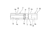
図1〜6は、本発明の実施の形態の1例を示している。本例の電力ケーブル用接続装置は、図1に示す様に、第一、第二の接続端子1、2と、接続筒3と、ロックナット4と、それぞれが弾性環状部材である、1対のばね座金5a、5bとから成る。これら各部材1〜5a、5bは、それぞれが、銅又は銅系合金等の電気抵抗の低い金属製である。又、前記両ばね座金5a、5bは、或る程度の弾性を有する合金製としている。この為に、必要に応じて、これら両ばね座金5a、5bを、燐青銅製、或いは、鉄系合金製とする事もできる。
1 to 6 show an example of an embodiment of the present invention. As shown in FIG. 1, the power cable connecting device of this example includes a pair of first and second connecting
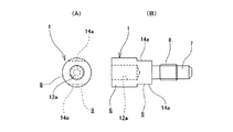
このうちの第一の接続端子1は、図2に示す様に、第一の接続部6と、挿入杆部7と、雄ねじ部8と、第一の係止部9とを備える。
このうちの第一の接続部6は、図1に鎖線で示した、互いに接続すべき1対の電力ケーブル10a、10bのうちの一方の電力ケーブル10aを構成する導体11aの端部を接続固定する為のものである。本例の場合、前記第一の接続部6は、圧縮端子と呼ばれるもので、中心部に、基端面{図2の(B)の左端面}の中央部に開口する、有底の円孔12aを有する。この円孔12aの内径は、前記第一の接続部6を塑性変形させる以前の状態で、前記導体11aの端部の外径よりも僅かに大きい。この様な第一の接続部6と導体11aの端部とを接続する作業は、一般的な電力ケーブル用接続装置を構成する圧縮端子の場合と同様にして行う。即ち、予め前記電力ケーブル10aの絶縁層13aの端部を除去する事により露出させた前記導体11aの端部を、前記円孔12a内に挿入する。そして、前記第一の接続部6を、その外径側から圧縮方向の力を加える事により、塑性変形させつつ直径を縮める。この作業により、前記導体11aの端部が前記円孔12aの内周面で強く抑え付けられて、この導体11aと前記第一の接続端子1とが、電気的且つ機械的に接続される。
Among these, the 1st connection terminal 1 is provided with the
Among these, the
又、前記挿入杆部7は、前記第一の接続端子1の先半部{図2の(B)の右半部}に設けられたもので、本例の場合には、円杆状に形成している。
又、前記雄ねじ部8は、前記挿入杆部7の軸方向中間部で、前記第一の接続部6に近い基端寄り{図2の(B)の左端寄り}部分を除いた部分に設けられている。前記雄ねじ部8の外径(山径)は、前記挿入杆部7の外径よりも大きい。
更に、前記第一の係止部9は、前記第一の接続端子1の回転を阻止する為の工具であるスパナを係止する為、前記第一の接続部6の先端部{図2の(B)の右端部}外周面に設けられている。本例の場合には、この第一の接続部6の先端部外周面の直径方向反対側2箇所位置に互いに平行な1対の平坦面14a、14aを形成し、これら両平坦面14a、14aに前記スパナを係止自在として、前記第一の係止部9としている。
The insertion hook 7 is provided in the front half of the first connection terminal 1 (the right half of FIG. 2B). Forming.
Further, the
Further, the first locking portion 9 is configured to lock a spanner, which is a tool for preventing the rotation of the first connection terminal 1, so that the front end portion of the first connection portion 6 {in FIG. Right end of (B)} provided on the outer peripheral surface. In the case of this example, a pair of
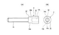
又、前記第二の接続端子2は、図3に示す様に、第二の接続部15と、ねじ杆部16と、第二の係止部17とを備える。
このうちの第二の接続部15は、互いに接続すべき前記1対の電力ケーブル10a、10bのうちの他方の電力ケーブル10bの導体11bの端部を接続固定する為のもので、前記第二の接続端子2の基端部{図3の(A)の右端部}に設けられている。この様な第二の接続部15も、前記第一の接続部6と同様の、圧縮端子と呼ばれる構造を採用している。即ち、この第二の接続部15の中心部に円孔12bを形成し、この円孔12b内に、前記導体11bの端部で絶縁層13bから露出した部分を挿入可能としている。
又、前記ねじ杆部16は、中間部乃至先半部に設けられている。このねじ杆部16の外周面に形成した雄ねじ部の仕様(ピッチ円直径、ピッチ)は、前記雄ねじ部8の仕様と同じである。
更に、前記第二の係止部17は、前記第二の接続端子2の回転を阻止する為の工具であるスパナを係止する為、前記第二の接続部15の基端部{図3の(A)の左端部}外周面に設けられている。本例の場合には、この第二の接続部15の先端部外周面の直径方向反対側2箇所位置に互いに平行な1対の平坦面14b、14bを形成し、これら両平坦面14b、14bに前記スパナを係止自在として、前記第二の係止部17としている。
Further, as shown in FIG. 3, the
Of these, the second connecting
Further, the
Further, the
又、前記接続筒3は、図4に示す様に、ねじ孔18と、第三の係止部19とを備える。このうちのねじ孔18は、前記雄ねじ部8及び前記ねじ杆部16を螺合させる為のもので、前記接続筒3の中心部に、この接続筒3を軸方向に貫通する状態で設けられている。又、前記第三の係止部19は、この接続筒3を回転させる為の工具であるスパナを係止する為、この接続筒3の中間部外周面に設けられている。本例の場合には、この接続筒3の中間部外周面の直径方向反対側2箇所位置に互いに平行な1対の平坦面14c、14cを形成し、これら両平坦面14c、14cに前記スパナを係止自在として、前記第三の係止部19としている。
Further, as shown in FIG. 4, the connection tube 3 includes a
又、前記ロックナット4は、前記ねじ杆部16に螺着されている。
又、前記両ばね座金5a、5bのうちの一方のばね座金5aは、図5に示す様に、前記挿入杆部7の基端寄り部分、即ち、前記第一の接続部6と前記雄ねじ部8との間部分に外嵌している。これに対して、他方のばね座金5bは、図6に示す様に、前記ねじ杆部16のうちで前記ロックナット4よりも先端寄り部分に外嵌している。
The lock nut 4 is screwed to the
Further, one of the
そして、図1に示す様に、前記雄ねじ部8を前記ねじ孔18に螺合し更に締め付ける事により、前記第一の接続部6の先端面と前記接続筒3の一端面との間で、前記一方のばね座金5aを圧縮している。又、前記ねじ杆部16を前記ねじ孔18に、このねじ杆部16の先端面が前記挿入杆部7の先端面に突き当たる迄螺合し更に締め付けている。更に、前記ロックナット4を前記接続筒3の他端面に向けて締め付ける事により、これらロックナット4と接続筒3の他端面との間で、前記他方のばね座金5bを圧縮している。
Then, as shown in FIG. 1, by screwing the
尚、前記ねじ孔18と、前記ねじ杆部及び前記雄ねじ部8とを螺合させ、更に前記ロックナット4を締め付けた状態では、必ずしも前記ねじ杆部16の先端面と前記挿入杆部7の先端面とが当接しているとは限らない。即ち、予め前記両接続端子1、2に結合固定した前記両ケーブル10a、10bを回転させず、前記接続筒3のみを回転させる事を前提とした場合、前記ねじ杆部16の外周面に形成したねじ山の位相と、前記雄ねじ部8を構成するねじ山の位相とを、完全に整合させる(前記両端面を当接させた状態で、両方のねじ山を前記ねじ孔18と螺合させる)事は、不可能ではないにしても面倒である。従って、前記両先端面同士が離隔して、これら両先端面同士の間に隙間が介在する可能性もある。前記ねじ孔18に対する前記雄ねじ部8の緩み止めの確実性を確保する為には、前記両先端面同士が当接している(強い力で突き合わされている)方が好ましいが、この様に構成する事は上述の様に面倒であり、必ずしも現実的ではない場合も多い。但し、前記ねじ孔18に対する前記雄ねじ部8の緩み止めは、前記一方のばね座金5aにより或る程度図れる。更には、組立完了後の電力ケーブル用接続装置を、ゴム等の弾性材製の絶縁筒により覆う事により、前記各部材1〜3の相対回転を防止できて、前記雄ねじ部8の緩み止めも図れる。従って、緩み止めに対する要求が極端に厳しくなければ、前記両先端面同士の間に隙間が存在していても良い。逆に言えば、緩み止めに対する要求が極端に厳しい場合には、前記両端面を当接させた状態で、前記両方のねじ山を前記ねじ孔18と螺合させるべく、これら両ねじ山の位相を規制して、前記両先端面同士の間に隙間が存在しない様にする事もできる。
In the state where the
上述の様な構造を有する電力ケーブル用接続装置は、次の様な手順で組み立てる。即ち、図5に示す様に、予め前記第一の接続端子1の前記挿入杆部7の基端寄り部分に前記一方のばね座金5aを外嵌しておく。且つ、図6に示す様に、予め前記第二の接続端子2の前記ねじ杆部16の基端部に前記ロックナット4を、中間部乃至先端部に前記接続筒3を、それぞれ螺着すると共に、これらロックナット4と接続筒3との間に前記他方のばね座金5bを挟持しておく。図6に示す様に、前記各部材2〜4、5bを組み合わせた状態で、前記ねじ杆部16の先端部は、この接続筒3の端部開口から僅かに突出するか、或いは、この端部開口よりも内側(この接続筒3の軸方向中間寄りに凹んだ位置)に存在する(前記ねじ杆部16が図示の例よりも短い場合)。
The power cable connecting device having the above-described structure is assembled by the following procedure. That is, as shown in FIG. 5, the one
そこで、図5に示した第一のユニット20と図6に示した第二のユニット21とを、互いに同心に配置した状態のまま互いに近づけ合う。前記両ねじ山の位相を規制した場合には、前記挿入杆部7の先端面と前記ねじ杆部の先端面とを突き当てる。そうでない場合には、これら両先端面同士を近接対向させる。次いで、これら両先端面同士を突き当てた状態、或いは近接対向させた状態から、前記接続筒3を回転させ、この接続筒3を前記挿入杆部7に向けて移動させる。更に、前記ねじ孔18と前記雄ねじ部8とを螺合させ、更に締め付ける。この締め付け作業は、前記第一の係止部9に係止したスパナにより前記第一の接続端子1の回転を阻止しつつ、前記第三の係止部19に係止したスパナにより、前記接続筒3を回転させる事により行う。そして、前記接続筒3の一端面と前記第一の接続部6の先端面との間で、前記一方のばね座金5aを強く圧縮する。
Therefore, the
次いで、前記ロックナット4を回転させつつ前記接続筒3に向け移動させ更に締め付ける。この締め付け作業は、前記第二の係止部17に係止したスパナにより前記第二の接続端子2の回転を阻止しつつ、前記ロックナット4に係止したスパナにより、このロックナット4を回転させる事により行う。そして、このロックナット4と前記接続筒3の他端面との間で、前記他方のばね座金5bを強く圧縮する。
Next, the lock nut 4 is moved toward the connecting tube 3 while being rotated and further tightened. In this tightening operation, the lock nut 4 is rotated by the spanner locked to the lock nut 4 while the rotation of the
前述の様に構成する本例の電力ケーブル用接続装置によれば、特殊な形状を有する部品を使用せず、低コストで造る事ができる。即ち、この電力ケーブル用接続装置を構成する第一の接続端子1と、第二の接続端子2と、接続筒3と、ロックナット4と、1対のばね座金5a、5bとは、何れも、単純な形状を有する為、何れも加工が容易であって、低コストで造れる。又、各部品1〜4を、それぞれ円形を基本とする断面形状に構成する事により、必要な強度を確保しつつ、外径寸法を小さくできる。
According to the power cable connecting device of this example configured as described above, it can be manufactured at low cost without using parts having a special shape. That is, the first connection terminal 1, the
又、各部材1〜4、5a、5bを組み合わせて電力ケーブル用接続装置を組み立てる作業は、第一〜第三の係止部9、17、19及びロックナット4の外周面にスパナを係止して、前記第一、第二の接続端子1、2の回転を阻止しつつ、接続筒3及びロックナット4を回転させる事により、容易に行える。又、接続作業に伴って電力ケーブル10a、10bが、問題となる程捩られる事もない。この為、接続作業を容易に行う事ができる。そして、組立作業を完了した状態では、雄ねじ部8及びねじ杆部16を構成する雄ねじ山の片側面と、ねじ孔18を構成する雌ねじ山の片側面とが、これら雄ねじ部8及びねじ杆部16とねじ孔18との締め付けに基づいて強く当接する。この様に、前記各ねじ山の側面同士が強く当接した状態では、前記第一、第二の接続端子2と前記接続筒3とが、電気的に確実に接続された状態となり、接続部の抵抗を低く抑える事ができる。しかも、接続部の機械強度を十分に確保できる。
Moreover, the operation | work which assembles the connection apparatus for electric power cables combining each member 1-4, 5a, 5b latches a spanner on the outer peripheral surface of the 1st-3rd latching | locking
又、ロックナット4の締め付け及び1対のばね座金5a、5bの弾力に基づいて、前記雄ねじ部8及びねじ杆部16と前記ねじ孔18との螺合部が不用意に緩む事もない。この為、前記接続部の電気抵抗を低く抑え、しかも、接続部の機械強度を十分に確保した状態を、長期間に亙って安定して維持できる。
更に、図6に示した様に、組立作業に先立って、第二の接続端子2とロックナット4とばね座金5bと接続筒3とを、電力ケーブル用接続装置の製造工場等で予め組み合わせておけば、この電力ケーブル用接続装置の組立現場での作業の容易化を図れる。又、部品を紛失する事で、組立作業が不能になる事もなくなる。
Further, the screwed portion of the
Furthermore, as shown in FIG. 6, prior to the assembly work, the
本発明を実施するに当たって、前記第一、第二の接続端子1、2に設けた前記第一、第二の接続部6、15に前記電力ケーブル10a、10bの導体11a、11bを接続する際に、これら両第一、第二の接続部6、15を六角ダイスにより圧縮する場合がある。この場合に、圧縮後に於けるこれら両第一、第二の接続部6、15の外周面の形状は六角形となり、そのままスパナ等の工具を係止可能になる。そこで、この様な形状を有する前記第一、第二の接続部6、15の外周面を、そのまま第一、第二の係止部として利用する事もできる。
In carrying out the present invention, when connecting the
又、前記第一、第二の接続端子1、2及び前記接続筒3の外周面には、必要に応じて錫(Sn)等のメッキを施す事もできる。
更に、図1に示した電力ケーブル用接続装置を組み立てた後、必要に応じてこの電力ケーブル用接続装置を、ゴム等の弾性材製の絶縁筒により覆う。この絶縁筒は、例えば特許文献2に記載される等により周知の様に、保持スリーブに外嵌した状態で、予め一方の電力ケーブルの周囲に配置しておく。そして、前記電力ケーブル用接続装置を組み立てた後、この電力ケーブル用接続装置の周囲に移動させてから、前記保持スリーブを抜き取る。この抜き取りに伴って前記絶縁筒の直径が弾性的に縮まり、前記電力ケーブル用接続装置が、前記導体11a、11aの端部で前記絶縁層13a、13bから露出した部分と共に、周囲との絶縁が確保され、且つ、水密を確保した状態で覆われる。尚、前記電力ケーブル用接続装置の絶縁処理に就いては、前記絶縁筒を外嵌する以外にも、絶縁性の熱収縮チューブを密に外嵌したり、或は、絶縁テープを巻回する事によっても行える。熱収縮チューブによる絶縁処理は、狭い場所での処理に有効であり、絶縁テープによる絶縁処理は、コスト低減の面から有効である。
In addition, the outer peripheral surfaces of the first and
Further, after assembling the power cable connecting device shown in FIG. 1, the power cable connecting device is covered with an insulating tube made of an elastic material such as rubber as necessary. As is well known, for example, as described in
1 第一の接続端子
2 第二の接続端子
3 接続筒
4 ロックナット
5a、5b ばね座金
6 第一の接続部
7 挿入杆部
8 雄ねじ部
9 第一の係止部
10a、10b 電力ケーブル
11a、11b 導体
12a、12b 円孔
13a、13b 絶縁層
14a、14b、14c 平坦面
15 第二の接続部
16 ねじ杆部
17 第二の係止部
18 ねじ孔
19 第三の係止部
20 第一のユニット
21 第二のユニット
DESCRIPTION OF SYMBOLS 1
Claims (2)
前記第二の接続端子は、基端部に設けられた、互いに接続すべき1対の電力ケーブルのうちの他方の電力ケーブルの端部を接続固定する為の第二の接続部と、中間部乃至先半部に設けられたねじ杆部とを備えたものであり、
前記接続筒は、中心部に軸方向に貫通する状態で設けられた、前記雄ねじ部及び前記ねじ杆部を螺合させる為のねじ孔とを備えたものであり、
前記ロックナットは、前記ねじ杆部に螺着されており、
前記両弾性環状部材のうちの一方の弾性環状部材は、前記挿入杆部の基端寄り部分に、他方の弾性環状部材は、前記ねじ杆部のうちで前記ロックナットよりも先端寄り部分に、それぞれ外嵌されており、
前記雄ねじ部を前記ねじ孔に螺合し更に締め付ける事により、前記第一の接続部の先端面と前記接続筒の一端面との間で前記一方の弾性環状部材を圧縮しており、
前記ねじ杆部を前記ねじ孔に螺合させた状態で、前記ロックナットを前記接続筒の他端面に向けて締め付ける事により、これらロックナットと接続筒の他端面との間で前記他方の弾性環状部材を圧縮している電力ケーブル用接続装置。 A first connection terminal, a second connection terminal, a connection tube, a lock nut, and a pair of elastic annular members, each of which is elastically compressible in the axial direction, each made of a conductive material The first connection terminal is a first connection portion provided in the base half portion for connecting and fixing one end of one of the power cables to be connected to each other. And an insertion flange provided in the first half, and a male screw portion having a diameter larger than that of the insertion flange provided in a portion excluding the proximal end portion close to the connection portion of the insertion flange And with
The second connection terminal is provided at the base end portion, a second connection portion for connecting and fixing the end portion of the other power cable of the pair of power cables to be connected to each other, and an intermediate portion Or a screw collar provided in the front half,
The connecting cylinder is provided with a screw hole for screwing the male screw portion and the screw flange portion provided in a state of penetrating in the axial direction at the center portion,
The lock nut is screwed to the screw flange portion,
One elastic annular member of the two elastic annular members is closer to the proximal end of the insertion flange, and the other elastic annular member is closer to the distal end than the lock nut of the screw flange. Each is fitted,
The one elastic annular member is compressed between the front end surface of the first connection portion and one end surface of the connection cylinder by screwing the male screw portion into the screw hole and further tightening.
By tightening the lock nut toward the other end surface of the connection tube in a state where the screw flange portion is screwed into the screw hole, the other elastic force is provided between the lock nut and the other end surface of the connection tube. A connecting device for a power cable compressing an annular member.
予め第一の接続端子の挿入杆部の基端寄り部分に、軸方向に弾性的に圧縮可能な一方の弾性環状部材を外嵌しておき、且つ、予め第二の接続端子のねじ杆部の基端部にロックナットを、中間部乃至先端部に接続筒を、それぞれ螺着すると共に、これらロックナットと接続筒との間に他方の弾性環状部材を挟持しておき、
前記挿入杆部の先端面と前記ねじ杆部の先端面とを突き当てた状態から前記接続筒を回転させ、この接続筒を前記挿入杆部に向けて移動させる事により、ねじ孔と雄ねじ部とを螺合させ更に締め付けて、前記接続筒の一端面と第一の接続部の先端面との間で一方の弾性環状部材を圧縮し、
次いで、前記ロックナットを回転させつつ前記接続筒に向け移動させ更に締め付けて、このロックナットとこの接続筒の他端面との間で他方の弾性環状部材を圧縮する電力ケーブル用接続装置の組立方法。 A method for assembling the power cable connecting device according to claim 1,
One elastic annular member that is elastically compressible in the axial direction is fitted in advance to the proximal end portion of the insertion hook portion of the first connection terminal in advance, and the screw hook portion of the second connection terminal is preliminarily fitted. A lock nut is screwed to the base end of each of the above, and a connection cylinder is screwed to each of the intermediate part to the tip part, and the other elastic annular member is sandwiched between the lock nut and the connection cylinder,
By rotating the connecting tube from a state in which the distal end surface of the insertion flange and the distal end surface of the screw flange are abutted, and moving the connection tube toward the insertion flange, a screw hole and a male screw portion And further tightening, compressing one elastic annular member between the one end surface of the connection tube and the tip surface of the first connection portion,
Next, a method for assembling the power cable connecting device for compressing the other elastic annular member between the lock nut and the other end face of the connecting tube by rotating the lock nut toward the connecting tube and further tightening the lock nut .
Priority Applications (1)
| Application Number | Priority Date | Filing Date | Title |
|---|---|---|---|
| JP2009123885A JP5259491B2 (en) | 2009-05-22 | 2009-05-22 | Power cable connection device and method for assembling the same |
Applications Claiming Priority (1)
| Application Number | Priority Date | Filing Date | Title |
|---|---|---|---|
| JP2009123885A JP5259491B2 (en) | 2009-05-22 | 2009-05-22 | Power cable connection device and method for assembling the same |
Publications (2)
| Publication Number | Publication Date |
|---|---|
| JP2010272390A JP2010272390A (en) | 2010-12-02 |
| JP5259491B2 true JP5259491B2 (en) | 2013-08-07 |
Family
ID=43420249
Family Applications (1)
| Application Number | Title | Priority Date | Filing Date |
|---|---|---|---|
| JP2009123885A Expired - Fee Related JP5259491B2 (en) | 2009-05-22 | 2009-05-22 | Power cable connection device and method for assembling the same |
Country Status (1)
| Country | Link |
|---|---|
| JP (1) | JP5259491B2 (en) |
Family Cites Families (2)
| Publication number | Priority date | Publication date | Assignee | Title |
|---|---|---|---|---|
| JPH02115258U (en) * | 1989-03-02 | 1990-09-14 | ||
| JP2008198509A (en) * | 2007-02-14 | 2008-08-28 | Toyokuni Electric Cable Co Ltd | Connection tool for low-voltage cable |
-
2009
- 2009-05-22 JP JP2009123885A patent/JP5259491B2/en not_active Expired - Fee Related
Also Published As
| Publication number | Publication date |
|---|---|
| JP2010272390A (en) | 2010-12-02 |
Similar Documents
| Publication | Publication Date | Title |
|---|---|---|
| US8152551B2 (en) | Port seizing cable connector nut and assembly | |
| RU2670955C2 (en) | Crimp contact | |
| US8591244B2 (en) | Cable connector | |
| JP2013541821A (en) | Electrical connector having grounding member | |
| US9742102B2 (en) | Connector seal device | |
| TW200822469A (en) | Coaxial cable connector with threaded post | |
| JP5312432B2 (en) | Power cable connection device and method for assembling the same | |
| JP5794434B2 (en) | Connecting the power cable | |
| CN102414927B (en) | Cable connection device | |
| US6203370B1 (en) | Electrical connector with an o-ring | |
| JP5259491B2 (en) | Power cable connection device and method for assembling the same | |
| CA2895724C (en) | Elbow with internal assembly system | |
| US20250219323A1 (en) | Tap plugs | |
| US20120252264A1 (en) | Method and apparatus for a snap retained push-on connector with port adapter | |
| JP2011249044A (en) | Connector and cable with connector | |
| US1677326A (en) | Connecter | |
| US10431919B2 (en) | Connector for electrical power cables | |
| JP2015035276A (en) | Detachable linear sleeve | |
| US6264503B1 (en) | Coaxial cable connector | |
| DE102009053137B3 (en) | Plug rotary connection for use in detachable electrical contact connector in photovoltaics, has plug contact comprising cylindrical head part that is formed for inserting into appropriate formed concavity at connecting part of contact bush | |
| JP2016136494A (en) | Equipment direct connection terminal and cable connection structure | |
| CA2864365C (en) | Mechanical lug | |
| JP2020190270A (en) | Long object connection tool | |
| US20200358222A1 (en) | Deadbreak connector | |
| JP6654482B2 (en) | Connection member for disconnection restoration |
Legal Events
| Date | Code | Title | Description |
|---|---|---|---|
| A621 | Written request for application examination |
Free format text: JAPANESE INTERMEDIATE CODE: A621 Effective date: 20120313 |
|
| A977 | Report on retrieval |
Free format text: JAPANESE INTERMEDIATE CODE: A971007 Effective date: 20130318 |
|
| TRDD | Decision of grant or rejection written | ||
| A01 | Written decision to grant a patent or to grant a registration (utility model) |
Free format text: JAPANESE INTERMEDIATE CODE: A01 Effective date: 20130326 |
|
| A61 | First payment of annual fees (during grant procedure) |
Free format text: JAPANESE INTERMEDIATE CODE: A61 Effective date: 20130424 |
|
| FPAY | Renewal fee payment (event date is renewal date of database) |
Free format text: PAYMENT UNTIL: 20160502 Year of fee payment: 3 |
|
| R150 | Certificate of patent or registration of utility model |
Ref document number: 5259491 Country of ref document: JP Free format text: JAPANESE INTERMEDIATE CODE: R150 Free format text: JAPANESE INTERMEDIATE CODE: R150 |
|
| LAPS | Cancellation because of no payment of annual fees |