JP5259381B2 - Imaging apparatus and imaging method - Google Patents
Imaging apparatus and imaging method Download PDFInfo
- Publication number
- JP5259381B2 JP5259381B2 JP2008331270A JP2008331270A JP5259381B2 JP 5259381 B2 JP5259381 B2 JP 5259381B2 JP 2008331270 A JP2008331270 A JP 2008331270A JP 2008331270 A JP2008331270 A JP 2008331270A JP 5259381 B2 JP5259381 B2 JP 5259381B2
- Authority
- JP
- Japan
- Prior art keywords
- color
- filter
- signal
- infrared
- green
- Prior art date
- Legal status (The legal status is an assumption and is not a legal conclusion. Google has not performed a legal analysis and makes no representation as to the accuracy of the status listed.)
- Expired - Fee Related
Links
Images


Classifications
-
- H—ELECTRICITY
- H04—ELECTRIC COMMUNICATION TECHNIQUE
- H04N—PICTORIAL COMMUNICATION, e.g. TELEVISION
- H04N23/00—Cameras or camera modules comprising electronic image sensors; Control thereof
- H04N23/80—Camera processing pipelines; Components thereof
- H04N23/84—Camera processing pipelines; Components thereof for processing colour signals
-
- H—ELECTRICITY
- H04—ELECTRIC COMMUNICATION TECHNIQUE
- H04N—PICTORIAL COMMUNICATION, e.g. TELEVISION
- H04N23/00—Cameras or camera modules comprising electronic image sensors; Control thereof
- H04N23/10—Cameras or camera modules comprising electronic image sensors; Control thereof for generating image signals from different wavelengths
- H04N23/12—Cameras or camera modules comprising electronic image sensors; Control thereof for generating image signals from different wavelengths with one sensor only
-
- H—ELECTRICITY
- H04—ELECTRIC COMMUNICATION TECHNIQUE
- H04N—PICTORIAL COMMUNICATION, e.g. TELEVISION
- H04N25/00—Circuitry of solid-state image sensors [SSIS]; Control thereof
- H04N25/10—Circuitry of solid-state image sensors [SSIS]; Control thereof for transforming different wavelengths into image signals
- H04N25/11—Arrangement of colour filter arrays [CFA]; Filter mosaics
- H04N25/13—Arrangement of colour filter arrays [CFA]; Filter mosaics characterised by the spectral characteristics of the filter elements
- H04N25/135—Arrangement of colour filter arrays [CFA]; Filter mosaics characterised by the spectral characteristics of the filter elements based on four or more different wavelength filter elements
-
- H—ELECTRICITY
- H04—ELECTRIC COMMUNICATION TECHNIQUE
- H04N—PICTORIAL COMMUNICATION, e.g. TELEVISION
- H04N2209/00—Details of colour television systems
- H04N2209/04—Picture signal generators
- H04N2209/041—Picture signal generators using solid-state devices
- H04N2209/042—Picture signal generators using solid-state devices having a single pick-up sensor
- H04N2209/045—Picture signal generators using solid-state devices having a single pick-up sensor using mosaic colour filter
Landscapes
- Engineering & Computer Science (AREA)
- Multimedia (AREA)
- Signal Processing (AREA)
- Physics & Mathematics (AREA)
- Spectroscopy & Molecular Physics (AREA)
- Color Television Image Signal Generators (AREA)
- Optical Filters (AREA)
Description
本発明は、CCD,CMOSセンサなどの固体撮像素子を有する撮像装置および撮像方法に関するものである。 The present invention relates to an imaging apparatus having a solid-state imaging device such as a CCD or CMOS sensor, and an imaging method.
一般に、画像入力機能を持った情報端末装置において、固体撮像素子として、たとえば、相補性金属酸化膜半導体(CMOS:Complementary Metal-oxide Semiconductor)センサや電荷結合素子(CCD:Charge Coupled Device)等が使用される。 In general, information terminal devices with an image input function use, for example, complementary metal-oxide semiconductor (CMOS) sensors or charge-coupled devices (CCDs) as solid-state image sensors. Is done.
CMOSセンサなどの固体撮像素子を有する撮像装置において、色の三原色である赤(R)、緑(G)、青(B)の色信号を得る場合、R、G、Bに対応する光の帯域を持つ色分離(カラー分離)フィルタを透過させる。 In an imaging device having a solid-state imaging device such as a CMOS sensor, when obtaining color signals of red (R), green (G), and blue (B), which are the three primary colors, light bands corresponding to R, G, and B Is transmitted through a color separation filter having color separation (color separation).
上記色分離フィルタは染料、もしくは顔料を用いて目的の色を透過するように形成される。ただし、色分離フィルタは、目的の色の透過機能を有すると同時に赤外領域も一定の割合で透過率を有してしまう。 The color separation filter is formed using a dye or a pigment so as to transmit a target color. However, the color separation filter has a transmission function of a target color, and at the same time, the infrared region also has a certain transmittance.
一方、人間の色に対する視感度特性は可視領域と呼ばれる380nmから780nmまでの感度特性を持っていると言われている。また、近赤外領域は780nmから2500nmまでの波長を、赤外領域は2500nm以上の波長を有している。これらの光は、直接肉眼で見ることはできないが、デジタルカメラやビデオカメラのモニタなどでは見ることができる。
そのため、撮像装置には、人間の目にあわせるために、一般的に赤外および近赤外領域の光線をカットする赤外線カットフィルタ(IRCF:Infrared Ray Cut Filter)を備える必要がある。
On the other hand, it is said that the visual sensitivity characteristic for human colors has a sensitivity characteristic from 380 nm to 780 nm called a visible region. The near infrared region has a wavelength from 780 nm to 2500 nm, and the infrared region has a wavelength of 2500 nm or more. These lights cannot be seen directly with the naked eye, but can be seen on a monitor of a digital camera or a video camera.
For this reason, the imaging apparatus generally needs to include an infrared ray cut filter (IRCF) that cuts off rays in the infrared and near-infrared regions in order to match the human eyes.
このように、一般的な撮像装置は、固体撮像素子の光入射側に近赤外領域および赤外領域の光線を通さない赤外線カットフィルタを備えている。
しかし、夜間など薄暗い場所で撮影を行う場合、近赤外領域および赤外領域が固体撮像素子の感度の強い領域であるため赤外線カットフィルタを外す必要がある。
そのため、一般的な撮像装置では、赤外線カットフィルタを着脱する機構を設ける必要があり、小型化、コスト面で問題を抱えていた。
このような問題から市場では、赤外線除去フィルタを光路上から抜き差しする切り替え機構を必要とせずに、夜間等の暗時での高感度撮影を可能とし、人間の視感度特性に合致するように昼間等の明時での色再現性を向上させることができる撮像装置が要求されている。
上記のように赤外線除去フィルタを着脱する機構を有しない技術として、たとえば赤外線除去フィルタを設けない手法が知られている。
しかし、赤外線除去フィルタを設けないと、夜間等の暗部での高感度撮影は可能であるが、昼間等の明時では、十分な色再現を行うことができないという問題点がある。
As described above, a general imaging apparatus includes an infrared cut filter that does not transmit light in the near infrared region and the infrared region on the light incident side of the solid-state imaging device.
However, when photographing in a dim place such as at night, it is necessary to remove the infrared cut filter because the near-infrared region and the infrared region are regions where the sensitivity of the solid-state imaging device is strong.
Therefore, it is necessary to provide a mechanism for attaching and detaching the infrared cut filter in a general imaging device, which has problems in terms of downsizing and cost.
Due to these problems, the market does not require a switching mechanism for inserting and removing the infrared filter from the optical path, enabling high-sensitivity shooting in the dark, such as at night, and daylighting to match the human visual sensitivity characteristics. Thus, there is a demand for an imaging apparatus that can improve color reproducibility in bright times.
As a technique that does not have a mechanism for attaching and detaching the infrared removal filter as described above, for example, a technique that does not provide an infrared removal filter is known.
However, if an infrared filter is not provided, high-sensitivity shooting can be performed in a dark part such as at night, but there is a problem that sufficient color reproduction cannot be performed in the daytime and other bright hours.
そこで、上記のような要望、問題点に応える撮像装置として、特許文献1に開示されているような技術を適用した撮像装置が提案されている。
この撮像装置は、赤外線カットフィルタの代わりに、可視領域における長波長領域を減衰させ、かつ、赤外領域を通すフィルタを設けることにより、赤外線カットフィルタを着脱する機構を設けることなく高感度で良好な色再現を得ている。
This imaging device has high sensitivity and good without providing a mechanism for attaching / detaching the infrared cut filter by providing a filter that attenuates the long wavelength region in the visible region and passes the infrared region instead of the infrared cut filter. Color reproduction.
しかし、上記のような技術を実現しようとすると、精度の高いホワイトバランスが要求されるため、色の偏りのある被写体においてはホワイトバランスの値を誤って算出してしまい、これが適正な色再現を行う補正量の推定に影響を及ぼしている。 However, when trying to realize the above-mentioned technology, high-accuracy white balance is required, so for subjects with color bias, the value of white balance is erroneously calculated, which results in proper color reproduction. This affects the estimation of the correction amount to be performed.
本発明は、より正確な補正量を推定することができ、ひいては昼間等の明時での色再現性を向上することが可能な撮像装置および撮像方法を提供することにある。 An object of the present invention is to provide an imaging apparatus and an imaging method capable of estimating a more accurate correction amount and thus improving the color reproducibility in the daytime and the like.
本発明の第1の観点の撮像装置は、複数の色のカラーフィルタを有するカラーフィルタ群と、前記各カラーフィルタを透過した光に対応する色信号を出力する撮像素子と、前記色信号を処理する色処理部と、を有し、前記カラーフィルタは、第1の色を含み、前記色処理部は、前記第1の色のカラーフィルタとは異なるカラーフィルタを透過した複数の色信号を合成して前記第1の色と可視領域において同等の分光感度特性を有する第2の色の色信号を取得し、可視領域において、前記第1の色の色信号と前記第2の色の色信号の値が略一致するようにゲインを調整し、前記第1の色の成分と前記第2の色の成分の差分または比率により、近赤外領域および赤外領域の入射光量を求める。 An image pickup apparatus according to a first aspect of the present invention includes a color filter group having a plurality of color filters, an image pickup device that outputs a color signal corresponding to light transmitted through each color filter, and processes the color signal. The color filter includes a first color, and the color processing unit synthesizes a plurality of color signals transmitted through a color filter different from the color filter of the first color. Then, a color signal of the second color having the same spectral sensitivity characteristic in the visible region as the first color is obtained, and the color signal of the first color and the color signal of the second color are obtained in the visible region. The gain is adjusted so that the values of the first and second colors substantially coincide with each other, and the incident light amounts in the near-infrared region and the infrared region are obtained from the difference or ratio between the first color component and the second color component .
好適には、前記カラーフィルタ群は、シアン、マゼンダ、イエローのカラーフィルタを含み、前記第1の色のカラーフィルタがレッド(R)、グリーン(G)、ブルー(B)のカラーフィルタのいずれかである。 Preferably, the color filter group includes cyan, magenta, and yellow color filters, and the first color filter is any one of red (R), green (G), and blue (B) color filters. It is.
好適には、前記カラーフィルタ群は、レッド、グリーン、ブルーのカラーフィルタを含み、前記第1の色のカラーフィルタがシアン、マゼンダ、イエローのカラーフィルタのいずれかである。 Preferably, the color filter group includes red, green, and blue color filters, and the first color filter is any one of cyan, magenta, and yellow color filters.
本発明の第2の観点の撮像方法は、第1の色のカラーフィルタと当該第1の色のカラーフィルタと異なるカラーフィルタを透過した光を撮像素子で受光して当該光に対応する色信号を生成するステップと、前記第1の色のカラーフィルタとは異なるカラーフィルタを透過した複数の色信号を合成して前記第1の色と可視領域において同等の分光感度特性を有する第2の色の色信号を取得するステップと、可視領域において、前記第1の色の色信号と前記第2の色の色信号の値が略一致するようにゲインを調整するステップと、前記第1の色の成分と前記第2の色の成分の差分または比率により、近赤外領域および赤外領域の入射光量を求めるステップとを有する。 The imaging method according to the second aspect of the present invention is a color signal corresponding to the light received by the imaging device through the light transmitted through the color filter of the first color and a color filter different from the color filter of the first color. And a second color having a spectral sensitivity characteristic equivalent to that of the first color in the visible region by combining a plurality of color signals transmitted through a color filter different from the color filter of the first color Obtaining a color signal of the first color, adjusting a gain so that values of the color signal of the first color and the color signal of the second color substantially coincide in the visible region, and the first color And determining the amount of incident light in the near-infrared region and the infrared region based on the difference or ratio between the component and the second color component .
本発明によれば、より正確な補正量を推定することができ、ひいては昼間等の明時での色再現性を向上することができる。 According to the present invention, it is possible to estimate a more accurate correction amount, and as a result, it is possible to improve color reproducibility in light hours such as daytime.
以下、本発明の実施形態を図面に関連付けて説明する。 Hereinafter, embodiments of the present invention will be described with reference to the drawings.
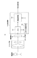
図1は、本発明の実施形態に係る撮像装置の構成例を示すブロック図である。 FIG. 1 is a block diagram illustrating a configuration example of an imaging apparatus according to an embodiment of the present invention.
本撮像装置10は、図1に示すように、レンズ系(光学系)11、撮像素子12、カラーフィルタ群13、および色処理部14を有する。
As shown in FIG. 1, the
レンズ系(光学系)11は、被写体OBJの像を、カラーフィルタ群13を通して撮像素子12の撮像面に結像する。
The lens system (optical system) 11 forms an image of the subject OBJ on the imaging surface of the
撮像素子12は、CCDやCMOSセンサにより形成され、複数の画素がマトリクス状に配列されている。
撮像素子12は、カラーフィルタ群13の各カラーフィルタを透過した光に対応する色信号を生成して、たとえば生成したアナログの色信号をデジタルの色信号に変換して色処理部14に出力する。
The
The
カラーフィルタ群13は、複数の色のカラー(色)フィルタを含み、撮像素子12の撮像面の光入射側に配置されている。
カラーフィルタ群13は、可視領域において、少なくとも4色以上のカラーフィルタを有する。
本実施形態では、カラーフィルタ群13が、4色のカラーフィルタを有する場合を例に説明する。
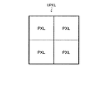
そして、本実施形態では、撮像素子12の画素配列として、図2に示すような、2×2のマトリクス配列された4つの画素PXLを、一組の単位画素UPXLとした場合を例に説明する。
以下に、4色のカラーフィルタにより形成される単位フィルタUFLTの構成例を示す。
The
The
In the present embodiment, a case where the
In the present embodiment, as an example of the pixel array of the
A configuration example of the unit filter UFLT formed by four color filters is shown below.
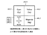
図3は、本実施形態の4色のカラーフィルタにより形成される単位フィルタの第1配置例を示す図である。 FIG. 3 is a diagram illustrating a first arrangement example of unit filters formed by the four color filters of the present embodiment.
図3の単位フィルタUFLT1は、図2の単位画素UPXLに対応して2×2のマトリクス配列された4色のカラーフィルタにより形成される。
具体的には、単位フィルタUFLT1は、補色となるシアン(Cyan:Cy)フィルタCFLT、マゼンダ(Magenda:Mg)フィルタMFLT、イエロー(Yellow:Ye)フィルタYFLTを有する。
そして、単位フィルタUFLT1は、色の三原色となるレッド(赤、R)、グリーン(緑、G)、ブルー(青、B)うちの1色で形成される原色フィルタPCFLTにより形成される。
The unit filter UFLT1 in FIG. 3 is formed by four color filters arranged in a 2 × 2 matrix corresponding to the unit pixel UPXL in FIG.
Specifically, the unit filter UFLT1 includes a cyan (Cy :) Cy filter CFLT, a magenta (Maganda: Mg) filter MFLT, and a yellow (Yellow: Ye) filter YFLT as complementary colors.
The unit filter UFLT1 is formed by a primary color filter PCFLT formed of one of the three primary colors red (red, R), green (green, G), and blue (blue, B).
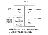
図4は、本実施形態の4色のカラーフィルタにより形成される単位フィルタの第2配置例を示す図である。 FIG. 4 is a diagram illustrating a second arrangement example of unit filters formed by the four color filters of the present embodiment.
図4の単位フィルタUFLT2は、図2の単位画素UPXLに対応して2×2のマトリクス配列された4色のカラーフィルタにより形成される。
具体的には、単位フィルタUFLT2は、色の三原色であるレッド(赤、R)フィルタRFLT、グリーン(緑、G)フィルタGFLT、ブルー(青、B)フィルタBFLTを有する。
そして、単位フィルタUFLT2の残りの1色は、補色となるシアン(Cy)、マゼンダ(Mg)、イエロー(Ye)のうちの1色で形成される補色フィルタCCFLTにより形成される。
The unit filter UFLT2 in FIG. 4 is formed by four color filters arranged in a 2 × 2 matrix corresponding to the unit pixel UPXL in FIG.
Specifically, the unit filter UFLT2 includes a red (red, R) filter RFLT, a green (green, G) filter GFLT, and a blue (blue, B) filter BFLT which are the three primary colors.
The remaining one color of the unit filter UFLT2 is formed by a complementary color filter CCFLT formed by one of cyan (Cy), magenta (Mg), and yellow (Ye) as complementary colors.
4色のカラーフィルタにより形成される単位フィルタUFLT1,2は、原色フィルタPCFLTまたは補色フィルタCCFLTの1色(第1の色)が残りの3色から少なくとも2色を用いることで表現できる色(第2の色)であるように形成される。 The unit filters UFLT1 and UFLT2 formed of four color filters are colors (first colors) that can be expressed by using at least two colors from the remaining three colors as one color (first color) of the primary color filter PCFLT or the complementary color filter CCFLT. 2 color).
色処理部14は、第1の色のカラーフィルタとは異なるカラーフィルタを透過した複数の色信号を合成して第1の色と可視領域において同等の分光感度特性を有する第2の色の色信号を取得し、第1の色のカラーフィルタを透過した色信号と第2の色の色信号を比較して、近赤外領域および赤外領域の入射光量を求める機能を有する。
たとえば色処理部14は、第1の色の成分CC1と第2の色の成分CC2の差分(CC1−CC2あるいはCC2−CC1)または比率(CC1/CC2あるいはCC2/CC1)により、近赤外領域および赤外領域の入射光量(入射赤外量)を求める。
そして、色処理部14は、視感度領域もしくは可視領域において、第1の色の色信号と第2の色の色信号の値が略一致するようにゲインを調整する機能を有する。
本実施形態の撮像装置10は、上記したとおりゲイン調整された信号において、視感度領域外、もしくは可視領域外の信号を含むことで、算出される信号と単画素のフィルタを透過した出力値は異なる。
The color processing unit 14 synthesizes a plurality of color signals transmitted through a color filter different from the color filter of the first color and colors the second color having the same spectral sensitivity characteristic in the visible region as the first color. A signal is acquired, and the color signal transmitted through the color filter of the first color is compared with the color signal of the second color to obtain the incident light amount in the near infrared region and the infrared region.
For example, the color processing unit 14 uses the difference (CC1-CC2 or CC2-CC1) or the ratio (CC1 / CC2 or CC2 / CC1) between the first color component CC1 and the second color component CC2 in the near infrared region. And the amount of incident light in the infrared region (incident infrared amount).
The color processing unit 14 has a function of adjusting the gain so that the values of the first color signal and the second color signal substantially match in the visibility region or the visible region.
The
なお、第1の色とは、図3の単位フィルタUFLT1を用いた場合、原色のフィルタの色、たとえばグリーン(G)であり、図4の単位フィルタUFLT2を用いた場合、補色フィルタの色、たとえばマゼンダ(Mg)である。
第2の色は、図3の単位フィルタUFLT1を用いた場合、シアンフィルタCFLT、マゼンダフィルタMFLT、イエローYFLTを透過した色信号のうち少なくとも2つの色信号を合成して形成される。
また、第2の色は、図4の単位フィルタUFLT2を用いた場合、レッドフィルタRFLT、グリーンフィルタGFLT、ブルーフィルタBFLTを透過した色信号のうち少なくとも2つの色信号を合成して形成される。
When the unit filter UFLT1 in FIG. 3 is used, the first color is the color of the primary color filter, for example, green (G). When the unit filter UFLT2 in FIG. 4 is used, the color of the complementary color filter is For example, magenta (Mg).
When the unit filter UFLT1 of FIG. 3 is used, the second color is formed by synthesizing at least two color signals among the color signals transmitted through the cyan filter CFLT, the magenta filter MFLT, and the yellow YFLT.
When the unit filter UFLT2 of FIG. 4 is used, the second color is formed by synthesizing at least two color signals among the color signals transmitted through the red filter RFLT, the green filter GFLT, and the blue filter BFLT.
図1の色処理部14は、メモリ141、近赤外領域および赤外領域の赤外光量(IR)推定部142、および画像処理部143を有する。
The color processing unit 14 of FIG. 1 includes a
メモリ141は、撮像素子12によるデジタル色信号を保持して、そのデータを赤外光量推定部142および画像処理部143に供給する。
メモリ141は、色信号によって算出された赤外量に対応した色補正係数を記憶する。メモリ141は、この色補正係数を画像処理部143に供給する。
The
The
赤外光量推定部142は、第1の色のカラーフィルタを透過した色信号と第2の色の色信号を比較して、近赤外領域および赤外領域の入射光量を推定する。
赤外光量推定部142は、第1の色の成分と第2の色の成分の差分または比率により、近赤外領域および赤外領域の入射光量を推定する。
赤外光量推定部142は、推定処理において、適正な色再現を実現するための赤外光量(補正量)を算出し、その結果を画像処理部143に出力する。
The infrared light
The infrared light
In the estimation process, the infrared light
画像処理部143は、赤外光量推定部142により赤外光量(補正量)情報を受けて、この赤外光量(補正量)に対応した色補正係数をメモリ141から読み出し、読み出した色補正係数を用いて元画像に対して色補正処理を行う。
The
撮像装置10は、色処理部14において、4色以上のカラーフィルタを有し、2色以上から算出される信号(第2の色の色信号)と、算出される信号と同等の波長領域のカラーフィルタを透過した信号(第1の色の色信号)を取得し両者で比較する。
色処理部14は、赤外光量推定部142において、たとえば比較した信号の差が大きければ大きいほど、赤外線の量が多いと判断し、逆に差が小さければ、赤外線は影響があるほどには含まれていないと判断する。
色処理部14は、赤外光量推定部142の赤外光量の推定結果を、画像処理部143の画像の色補正処理系にフィードバックする。
The
In the infrared light
The color processing unit 14 feeds back the estimation result of the infrared light amount of the infrared light
撮像装置10は、たとえば図3のカラーフィルタ群を採用している場合には、補色フィルタのうち、シアン(Cy)、マゼンダ(Mg)、イエロー(Ye)のカラーフィルタを透過して得られた色信号から算出されるグリーン成分(第2の色成分)とグリーンフィルタGFLTを透過したグリーン成分(第1の色成分)を比較することで、入射した光の赤外光量を推定する。
推定された赤外光量を基に色補正へフィードバックをかけて、色再現性を向上させる。
For example, when the color filter group of FIG. 3 is employed, the
Based on the estimated amount of infrared light, feedback is made to color correction to improve color reproducibility.
以下、本実施形態の撮像装置10における色再現処理についてフィルタ特性や赤外光量推定原理等を含め、図5〜図16に関連付けてさらに詳述する。
Hereinafter, the color reproduction process in the
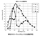
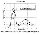
図5は、例として図3の補色(シアン、マゼンダ、イエロー+グリーン)の単位フィルタを装着した固体撮像素子の分光感度特性を示す図である。
図6は、例として原色のカラーフィルタ(レッド、ブルー、グリーン)を装着した固体撮像素子の分光感度特性を示す図である。
FIG. 5 is a diagram showing the spectral sensitivity characteristics of a solid-state imaging device equipped with the unit filters of the complementary colors (cyan, magenta, yellow + green) in FIG. 3 as an example.
FIG. 6 is a diagram showing the spectral sensitivity characteristics of a solid-state imaging device equipped with primary color filters (red, blue, green) as an example.
図5および図6において、横軸が波長を、縦軸が量子効率(Quantum Efficiency)をそれぞれ示す。
図5中、Aで示す曲線がシアンフィルタCFLTの分光感度特性を、Bで示す曲線がグリーンフィルタGFLTの分光感度特性を、Cで示す曲線がイエローフィルタYFLTの分光感度特性を、Dで示す曲線がマゼンダフィルタMFLTの分光感度特性をそれぞれ示している。
図6中、Aで示す曲線がレッドフィルタRFLTの分光感度特性を、Bで示す曲線がグリーンフィルタGFLTの分光感度特性を、Cで示す曲線がブルーフィルタBFLTの分光感度特性をそれぞれ示している。
5 and 6, the horizontal axis indicates the wavelength, and the vertical axis indicates the quantum efficiency.
In FIG. 5, the curve indicated by A indicates the spectral sensitivity characteristic of the cyan filter CFLT, the curve indicated by B indicates the spectral sensitivity characteristic of the green filter GFLT, and the curve indicated by C indicates the spectral sensitivity characteristic of the yellow filter YFLT by D. Respectively show the spectral sensitivity characteristics of the magenta filter MFLT.
In FIG. 6, the curve indicated by A indicates the spectral sensitivity characteristic of the red filter RFLT, the curve indicated by B indicates the spectral sensitivity characteristic of the green filter GFLT, and the curve indicated by C indicates the spectral sensitivity characteristic of the blue filter BFLT.
図5および図6に示すように、補色のカラーフィルタを用いた方が原色のカラーフィルタを用いる場合より、量子効率は良好である。 As shown in FIGS. 5 and 6, the quantum efficiency is better when the complementary color filter is used than when the primary color filter is used.
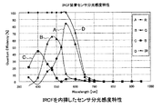
図7は、原色のカラーフィルタを装着した固体撮像素子にIRCF(赤外線カットフィルタ)を加えた分光透過率特性を示す図である。 Figure 7 is a diagram showing a spectral transmittance characteristic plus IRCF (infrared cut filter) to a solid-state imaging device equipped with a color filter of primary colors.
図7において、横軸が波長を、縦軸が量子効率(Quantum Efficiency)をそれぞれ示す。
図7中、Aで示す曲線がレッドフィルタRFLTの分光透過率特性を、Bで示す曲線がグリーンフィルタGFLTの分光透過率特性を、Cで示す曲線がブルーフィルタBFLTの分光透過率特性を、Dで示す曲線がIRCFの分光透過率特性をそれぞれ示している。
赤外線カットフィルタIRCFは、略700nm以上の波長領域で遮断効果を十分に発現する。
In FIG. 7, the horizontal axis indicates the wavelength, and the vertical axis indicates the quantum efficiency.
In FIG. 7, the curve indicated by A indicates the spectral transmittance characteristics of the red filter RFLT, the curve indicated by B indicates the spectral transmittance characteristics of the green filter GFLT, and the curve indicated by C indicates the spectral transmittance characteristics of the blue filter BFLT. Curves indicated by indicate the spectral transmittance characteristics of IRCF.
The infrared cut filter IRCF sufficiently exhibits a blocking effect in a wavelength region of approximately 700 nm or more.
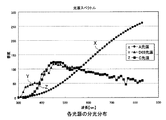
図8は、例としてA光源、D65光源、C光源の分光分布を示す図である。
A光源は色温度2850度K前後で、家庭用の電球とほぼ同等の光であり、C光源は色温度6740度K前後で昼光に近い光である。また、D65光源は6500度K前後で、C光源よりもさらに自然光に近い光である。
FIG. 8 is a diagram showing spectral distributions of an A light source, a D65 light source, and a C light source as an example.
The A light source has a color temperature of about 2850 degrees K and is almost equivalent to a light bulb for home use, and the C light source has a color temperature of about 6740 degrees K and is close to daylight. In addition, the D65 light source is around 6500 degrees K and is light closer to natural light than the C light source.
図8において、横軸が波長を、縦軸が感度をそれぞれ示している。
図8中、Xで示す曲線がA光源の分光分布特性を、Yで示す曲線がD65光源の分光分布特性を、Zで示す曲線がC光源の分光分布特性をそれぞれ示している。
In FIG. 8, the horizontal axis indicates the wavelength and the vertical axis indicates the sensitivity.
In FIG. 8, the curve indicated by X indicates the spectral distribution characteristic of the A light source, the curve indicated by Y indicates the spectral distribution characteristic of the D65 light source, and the curve indicated by Z indicates the spectral distribution characteristic of the C light source.
図9は、自然の葉と人工の草(葉)の色の分光反射率を示す図である。 FIG. 9 is a diagram showing the spectral reflectance of natural leaves and artificial grass (leaf) colors.
図9において、横軸が波長を、縦軸が量子効率(Quantum Efficiency)をそれぞれ示す。
図9中、Aで示す曲線が自然の葉の反射率特性を、Bで示す曲線が人工の草の反射率特性をそれぞれ示している。
図9から、自然の葉が、人工の草より赤外光を反射していることが分かる。
In FIG. 9, the horizontal axis indicates the wavelength, and the vertical axis indicates the quantum efficiency.
In FIG. 9, the curve indicated by A indicates the reflectance characteristics of natural leaves, and the curve indicated by B indicates the reflectance characteristics of artificial grass.
FIG. 9 shows that natural leaves reflect infrared light from artificial grass.
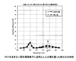
図10は、赤外線カットフィルタIRCFを有する固体撮像素子に自然と人工の葉を撮像した時の分光特性を示す図である。 FIG. 10 is a diagram showing the spectral characteristics when a natural leaf is imaged naturally on a solid-state imaging device having an infrared cut filter IRCF.
図10において、横軸が波長を、縦軸が量子効率(Quantum Efficiency)をそれぞれ示す。
図10中、Aで示す曲線が自然の葉の反射率特性を、Bで示す曲線が人工の草の反射率特性をそれぞれ示している。
図10に示すように、赤外線カットフィルタIRCFにより赤外成分がカットされているため、自然の葉も人工の草も同じ緑として写る。
これは、人間の視感度領域内で色が表現されているためである。
In FIG. 10, the horizontal axis indicates the wavelength, and the vertical axis indicates the quantum efficiency.
In FIG. 10, the curve indicated by A indicates the reflectance characteristics of natural leaves, and the curve indicated by B indicates the reflectance characteristics of artificial grass.
As shown in FIG. 10, since the infrared component is cut by the infrared cut filter IRCF, natural leaves and artificial grass appear as the same green.
This is because the color is expressed within the human visibility region.
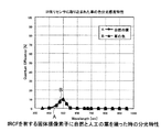
図11は、赤外線カットフィルタIRCFを含まない固体撮像素子に自然と人工の葉を撮像した時の分光特性を示す図である。 FIG. 11 is a diagram illustrating the spectral characteristics when a natural image of an artificial leaf is captured by a solid-state imaging device that does not include the infrared cut filter IRCF.
図11において、横軸が波長を、縦軸が量子効率(Quantum Efficiency)をそれぞれ示す。
図11中、Aで示す曲線が自然の葉の反射率特性を、Bで示す曲線が人工の草の反射率特性をそれぞれ示している。
図11は、赤外線カットフィルタIRCFがないために、人間の視感度領域外となる赤外の反射まで撮像素子が受光していることを示す。
そのため、赤外線カットフィルタIRCFが無いと、人工の葉(草)と自然の葉では異なった色として出力されてしまう。
当然ながら、人間には、この赤外領域に感度を持たないために、両者は同じ色として写る。
In FIG. 11, the horizontal axis indicates the wavelength, and the vertical axis indicates the quantum efficiency.
In FIG. 11, the curve indicated by A indicates the reflectance characteristics of natural leaves, and the curve indicated by B indicates the reflectance characteristics of artificial grass.
FIG. 11 shows that the imaging device receives light up to infrared reflection outside the human visibility region because there is no infrared cut filter IRCF.
Therefore, if there is no infrared cut filter IRCF, artificial leaves (grass) and natural leaves are output as different colors.
Naturally, since humans do not have sensitivity in this infrared region, both appear as the same color.
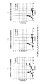
図12(A)〜(C)は、赤外線カットフィルタIRCFを含んだ状態での図8の特性を有する各光源の光を通した時の分光特性を示す図である。 12A to 12C are diagrams showing spectral characteristics when light of each light source having the characteristics of FIG. 8 including the infrared cut filter IRCF is passed.
図12(A)〜(C)において、横軸が波長を、縦軸が量子効率(Quantum Efficiency)をそれぞれ示す。
図12(A)はA光源の光を通したときの分光特性を、図12(B)はD65光源の光を通したときの分光特性を、図12(C)はC光源の光を通したときの分光特性をそれぞれ示している。
図12(A)〜(C)に示すように、光源毎に赤外線を含む量が異なるが、赤外線カットフィルタIRCFによって、カットされているため、常に人間の見た目と同じようにして見ることができる。
12A to 12C, the horizontal axis indicates the wavelength, and the vertical axis indicates the quantum efficiency.
12A shows the spectral characteristics when the light from the A light source is passed, FIG. 12B shows the spectral characteristics when the light from the D65 light source is passed, and FIG. The spectral characteristics are shown respectively.
As shown in FIGS. 12A to 12C, although the amount of infrared rays is different for each light source, since it is cut by the infrared cut filter IRCF, it can always be seen in the same manner as the human appearance. .
図13(A)〜(C)は、赤外線カットフィルタIRCFを含まない状態での図8の特性を有する各光源の光を通した時の分光特性を示す図である。 FIGS. 13A to 13C are diagrams showing spectral characteristics when light from each light source having the characteristics shown in FIG. 8 is passed without including the infrared cut filter IRCF.
図13(A)〜(C)において、横軸が波長を、縦軸が量子効率(Quantum Efficiency)をそれぞれ示す。
図13(A)はA光源の光を通したときの分光特性を、図13(B)はD65光源の光を通したときの分光特性を、図13(C)はC光源の光を通したときの分光特性をそれぞれ示している。
図13(A)〜(C)に示すように、光源毎に赤外線を含む量が異なるため、光源によって、人工の葉と自然の葉が大分異なってくる。
図にある通り、色温度が低ければ、それだけ赤外線量が増えてくる傾向にある。色温度が高い、たとえば図13(B)、(C)のような環境下であれば問題がないが、色温度が低い、たとえば図13(A)のような環境下では、色味が変わってきてしまう。
13A to 13C, the horizontal axis indicates the wavelength, and the vertical axis indicates the quantum efficiency.
13A shows the spectral characteristics when the light of the A light source is passed, FIG. 13B shows the spectral characteristics when the light of the D65 light source is passed, and FIG. The spectral characteristics are shown respectively.
As shown in FIGS. 13A to 13C, since the amount of infrared rays is different for each light source, the artificial leaf and the natural leaf are largely different depending on the light source.
As shown in the figure, when the color temperature is low, the amount of infrared rays tends to increase accordingly. There is no problem if the color temperature is high, for example, in an environment as shown in FIGS. 13B and 13C, but the color changes in an environment where the color temperature is low, such as in FIG. 13A. I will come.
図14は、本実施形態においてゲイン調整をせずに、補色より求められた第2の色としてのグリーンとグリーンフィルタを透過した第1の色としてのグリーンの感度の比較例を示す図である。 FIG. 14 is a diagram illustrating a comparative example of the sensitivity of green as the second color obtained from the complementary color and green as the first color transmitted through the green filter without gain adjustment in the present embodiment. .
このとき、第2の色は一例として以下の数式(1)で求めることが可能である。その他、第1の色がレッド、ブルーである場合の第2の色の求め方を数式(2)、(3)に示す。
ただし、Gはグリーン、Rはレッド、Bはブルー、Cyはシアン、Mgはマゼンダ、Yeはイエローを表している。
At this time, the second color can be obtained by the following formula (1) as an example. In addition, formulas (2) and (3) show how to obtain the second color when the first color is red or blue.
However, G represents green, R represents red, B represents blue, Cy represents cyan, Mg represents magenta, and Ye represents yellow.
G=(Cy+Ye−Mg)/2 ・・・(1)
R=(Ye+Mg−Cy)/2 ・・・(2)
B=(Mg+Cy−Ye)/2 ・・・(3)
G = (Cy + Ye-Mg) / 2 (1)
R = (Ye + Mg-Cy) / 2 (2)
B = (Mg + Cy-Ye) / 2 (3)
図14において、横軸が波長を、縦軸が量子効率(Quantum Efficiency)をそれぞれ示す。
図14中、Aで示す曲線が第1の色としてのグリーンの感度特性を、Bで示す曲線が第2の色としてのグリーンの感度特性をそれぞれ示している。
In FIG. 14, the horizontal axis indicates the wavelength, and the vertical axis indicates the quantum efficiency.
In FIG. 14, the curve indicated by A indicates the sensitivity characteristic of green as the first color, and the curve indicated by B indicates the sensitivity characteristic of green as the second color.
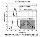
図15は、本実施形態においてゲイン調整をして、補色より求められた第2の色としてのグリーンとグリーンフィルタを透過した第1の色としてのグリーンの感度の比較例を示す図である。
すなわち、図15は、図14に対して、可視領域内で等しくなるようにゲインを調整した両者の比較を示す。
FIG. 15 is a diagram illustrating a comparative example of the sensitivity of green as the second color obtained from the complementary color and green as the first color transmitted through the green filter after gain adjustment in the present embodiment.
That is, FIG. 15 shows a comparison of FIG. 14 with the gain adjusted to be equal in the visible region.
図15において、横軸が波長を、縦軸が量子効率(Quantum Efficiency)をそれぞれ示す。
図15中、Aで示す曲線が第1の色としてのグリーンの感度特性を、Bで示す曲線が第2の色としてのグリーンの感度特性をそれぞれ示している。
ここから分かるのは、光源と物体の反射特性によって仮に人間の視感度領域に分光特性が収まった場合には、補色から算出されたグリーンとグリーンのカラーフィルタを透過したグリーンは同一の信号とならなければならない。
上記分光特性が赤外線を含む場合は、この算出されたグリーンと透過したグリーンの間に差があるため出力値が異なってくる。
差が大きければ大きいほど、赤外線を多く含んでいる事を意味する。信号の差分によって赤外線がどの程度、現状含まれているかを推定して、色補正を行う。
色補正を行う理由は、赤外線カットフィルタIRCFを含まないと視感度領域から外れた光を撮像素子が受光してしまうため、色がおかしくなってくるからである。
In FIG. 15, the horizontal axis indicates the wavelength and the vertical axis indicates the quantum efficiency.
In FIG. 15, the curve indicated by A indicates the sensitivity characteristic of green as the first color, and the curve indicated by B indicates the sensitivity characteristic of green as the second color.
It can be seen from this that if the spectral characteristics are within the human visibility range due to the reflection characteristics of the light source and the object, the green calculated from the complementary color and the green transmitted through the green color filter must be the same signal. There must be.
When the spectral characteristics include infrared rays, the output value differs because there is a difference between the calculated green and the transmitted green.
The larger the difference, the more infrared is included. Color correction is performed by estimating how much infrared light is currently included based on the signal difference.
The reason why the color correction is performed is that, if the infrared cut filter IRCF is not included, the image sensor receives light deviating from the visibility region, so that the color becomes strange.
次に、上記構成による撮像装置10の色再現動作について図16に関連付けて説明する。
図16は、カラーフィルタ群を通して固体撮像素子に光が到達してから補正までのフローチャートを示す図である。
Next, the color reproduction operation of the
FIG. 16 is a diagram illustrating a flowchart from the arrival of light to the solid-state imaging device through the color filter group to the correction.
この例は、図3の構成を有し、図5の特性を有する補色系フィルタを用いた場合の動作例を示している。
撮像装置10は、たとえば図3のカラーフィルタ群を採用している場合には、シアンフィルタCFLT、マゼンダフィルタMFLT、イエローフィルタYFLT、グリーンフィルタGFLT(補色フィルタCCFLT)によって分光され、各画素による色信号がデジタル信号として色処理部14に供給される(ST0、ST1)。
色処理部14の赤外光量推定部142において、補色フィルタであるシアンフィルタCFLT、マゼンダフィルタMFLT、イエローフィルタYFLTを透過して得られた色信号からRGB成分が算出される(ST2)。本例では、補色によって第2の色としてのグリーン信号が形成される。
また、赤外光量推定部142において、グリーンフィルタGFLTを透過したグリーン成分が第1の色として得られる(ST3)。
赤外光量推定部142においては、補色フィルタのうち、シアン(Cy)、マゼンダ(Mg)、イエロー(Ye)の色信号から算出されるグリーン成分(第2の色成分)とグリーンフィルタGFLTを透過したグリーン成分(第1の色成分)を比較することで、入射した光の赤外光量が推定される。
そして、画像処理部143において、推定された赤外光量を基にRGBの色補正が行われ(ST5)、補正画像が後段の信号処理系等に出力される(ST6)。
This example shows an operation example when the complementary color filter having the configuration of FIG. 3 and having the characteristics of FIG. 5 is used.
For example, when the color filter group in FIG. 3 is employed, the
In the infrared light
In addition, in the infrared light
In the infrared light
Then, the
以上説明したように、本実施形態によれば、撮像装置10は、色処理部14において、4色以上のカラーフィルタを有し、2色以上から算出される信号(第2の色の色信号)と、算出される信号と同等の波長領域のカラーフィルタを透過した信号(第1の色の色信号)を取得し両者で比較する。
色処理部14は、赤外光量推定部142において、たとえば比較した信号の差が大きければ大きいほど、赤外線の量が多いと判断し、逆に差が小さければ、赤外線は影響があるほどには含まれていないと判断する。
色処理部14は、赤外光量推定部142の赤外光量の推定結果を、画像処理部143の画像の色補正にフィードバックする。
したがって、本実施形態によれば、以下の効果を得ることができる。
As described above, according to the present embodiment, the
In the infrared light
The color processing unit 14 feeds back the estimation result of the infrared light amount of the infrared light
Therefore, according to the present embodiment, the following effects can be obtained.
赤外線カットフィルタを光路上から移動させる駆動部を必要とせずに、人間の視感度特性に合致する撮像装置を実現することが可能である。
複数の色を有するカラーフィルタにおいて、少なくとも1色を他の色から合成して表現できる色とする。この色において、単画素を透過した色信号と、複数の画素から算出される色信号を比較して求めた赤外光量を用いていることにより、赤外線カットフィルタを設けることなく、高感度で良好な色再現が可能となる。
すなわち、本実施形態によれば、赤外線カットフィルタを光路上から抜き差しする切り替え機構を必要とせずに、夜間等の暗時での高感度撮影を可能とし、人間の視感度特性に合致するように、より正確な補正量を推定することができ、ひいては昼間等の明時での色再現性を向上することができる。
It is possible to realize an imaging device that matches the human visual sensitivity characteristics without requiring a driving unit that moves the infrared cut filter from the optical path.
In a color filter having a plurality of colors, at least one color is a color that can be expressed by being synthesized from other colors. In this color, by using the infrared light quantity obtained by comparing the color signal transmitted through a single pixel and the color signal calculated from a plurality of pixels, high sensitivity and goodness without providing an infrared cut filter Color reproduction is possible.
That is, according to the present embodiment, it is possible to perform high-sensitivity shooting in the dark, such as at night, without the need for a switching mechanism for inserting and removing the infrared cut filter from the optical path so as to match the human visual sensitivity characteristics. Therefore, it is possible to estimate a more accurate correction amount, and as a result, it is possible to improve the color reproducibility in the daytime and the like.
なお、以上詳細に説明した方法は、上記手順に応じたプログラムとして形成し、CPU等のコンピュータで実行するように構成することも可能である。
また、このようなプログラムは、半導体メモリ、磁気ディスク、光ディスク、フロッピー(登録商標)ディスク等の記録媒体、この記録媒体をセットしたコンピュータによりアクセスし上記プログラムを実行するように構成可能である。
Note that the method described above in detail can be formed as a program according to the above-described procedure and executed by a computer such as a CPU.
Further, such a program can be configured to be accessed by a recording medium such as a semiconductor memory, a magnetic disk, an optical disk, a floppy (registered trademark) disk, or the like, and to execute the program by a computer in which the recording medium is set.
10・・・撮像装置、11・・・レンズ系(光学系)、12・・・撮像素子、13・・・カラーフィルタ群、14・・・色処理部。
DESCRIPTION OF
Claims (4)
前記各カラーフィルタを透過した光に対応する色信号を出力する撮像素子と、
前記色信号を処理する色処理部と、を有し、
前記カラーフィルタは、
第1の色を含み、
前記色処理部は、
前記第1の色のカラーフィルタとは異なるカラーフィルタを透過した複数の色信号を合成して前記第1の色と可視領域において同等の分光感度特性を有する第2の色の色信号を取得し、可視領域において、前記第1の色の色信号と前記第2の色の色信号の値が略一致するようにゲインを調整し、前記第1の色の成分と前記第2の色の成分の差分または比率により、近赤外領域および赤外領域の入射光量を求める
撮像装置。 A group of color filters having a plurality of color filters;
An image sensor that outputs a color signal corresponding to the light transmitted through each of the color filters;
A color processing unit for processing the color signal,
The color filter is
Including a first color,
The color processing unit
A plurality of color signals transmitted through a color filter different from the color filter of the first color are combined to obtain a color signal of a second color having spectral sensitivity characteristics equivalent to the first color in the visible region. In the visible region, the gain is adjusted so that the values of the color signal of the first color and the color signal of the second color substantially coincide, and the first color component and the second color component An imaging device that obtains the amount of incident light in the near infrared region and the infrared region based on the difference or ratio .
シアン、マゼンダ、イエローのカラーフィルタを含み、
前記第1の色のカラーフィルタがレッド、グリーン、ブルーのカラーフィルタのいずれかである
請求項1に記載の撮像装置。 The color filter group includes:
Including cyan, magenta, yellow color filters,
The imaging apparatus according to claim 1, wherein the first color filter is one of a red, green, and blue color filter.
レッド、グリーン、ブルーのカラーフィルタを含み、
前記第1の色のカラーフィルタがシアン、マゼンダ、イエローのカラーフィルタのいずれかである
請求項1に記載の撮像装置。 The color filter group includes:
Includes red, green and blue color filters,
The imaging apparatus according to claim 1, wherein the color filter of the first color is any one of cyan, magenta, and yellow color filters.
前記第1の色のカラーフィルタとは異なるカラーフィルタを透過した複数の色信号を合成して前記第1の色と可視領域において同等の分光感度特性を有する第2の色の色信号を取得するステップと、
可視領域において、前記第1の色の色信号と前記第2の色の色信号の値が略一致するようにゲインを調整するステップと、
前記第1の色の成分と前記第2の色の成分の差分または比率により、近赤外領域および赤外領域の入射光量を求めるステップと
を有する撮像方法。 Receiving light that has passed through a color filter of the first color and a color filter different from the color filter of the first color with an imaging device, and generating a color signal corresponding to the light;
A plurality of color signals transmitted through a color filter different from the color filter of the first color are combined to obtain a color signal of the second color having the same spectral sensitivity characteristic in the visible region as the first color. Steps,
Adjusting the gain so that the values of the color signal of the first color and the color signal of the second color substantially match in the visible region;
An imaging method comprising: calculating an incident light amount in a near infrared region and an infrared region based on a difference or ratio between the first color component and the second color component .
Priority Applications (2)
| Application Number | Priority Date | Filing Date | Title |
|---|---|---|---|
| JP2008331270A JP5259381B2 (en) | 2008-12-25 | 2008-12-25 | Imaging apparatus and imaging method |
| US12/647,101 US8508609B2 (en) | 2008-12-25 | 2009-12-24 | Image pickup apparatus, imaging method and method for correcting infrared light |
Applications Claiming Priority (1)
| Application Number | Priority Date | Filing Date | Title |
|---|---|---|---|
| JP2008331270A JP5259381B2 (en) | 2008-12-25 | 2008-12-25 | Imaging apparatus and imaging method |
Publications (2)
| Publication Number | Publication Date |
|---|---|
| JP2010154335A JP2010154335A (en) | 2010-07-08 |
| JP5259381B2 true JP5259381B2 (en) | 2013-08-07 |
Family
ID=42284438
Family Applications (1)
| Application Number | Title | Priority Date | Filing Date |
|---|---|---|---|
| JP2008331270A Expired - Fee Related JP5259381B2 (en) | 2008-12-25 | 2008-12-25 | Imaging apparatus and imaging method |
Country Status (2)
| Country | Link |
|---|---|
| US (1) | US8508609B2 (en) |
| JP (1) | JP5259381B2 (en) |
Families Citing this family (12)
| Publication number | Priority date | Publication date | Assignee | Title |
|---|---|---|---|---|
| JP5910043B2 (en) * | 2011-12-02 | 2016-04-27 | 富士通株式会社 | Imaging apparatus, image processing program, image processing method, and image processing apparatus |
| WO2014041866A1 (en) * | 2012-09-14 | 2014-03-20 | シャープ株式会社 | Sensor, display device, control program, and recording medium |
| CN103353621B (en) * | 2013-06-14 | 2015-08-26 | 广东欧珀移动通信有限公司 | A kind of method that mobile terminal proximity transducer is calibrated and this mobile terminal |
| WO2016171088A1 (en) * | 2015-04-23 | 2016-10-27 | 富士フイルム株式会社 | Image capturing device, image processing method of image capturing device, and program |
| JP6531522B2 (en) * | 2015-07-01 | 2019-06-19 | 富士通株式会社 | Color correction program, color correction method and color correction apparatus |
| US10863115B2 (en) * | 2016-06-24 | 2020-12-08 | Nec Corporation | Generation of visible and near-infrared images based on estimated incident light spectral characteristics and image capturing device spectral sensitivity characteristics |
| EP3489889B1 (en) * | 2016-07-25 | 2023-09-20 | Nec Corporation | Information processing device, information processing method, and recording medium |
| CN106941551B (en) * | 2017-02-28 | 2020-07-07 | 陈惠金 | Mobile terminal, mobile terminal light sensation calibration device, method and system |
| KR102412278B1 (en) * | 2017-11-06 | 2022-06-24 | 삼성전자 주식회사 | Camera module including filter array of complementary colors and electronic device including the camera module |
| CN115004692A (en) * | 2020-02-26 | 2022-09-02 | 索尼半导体解决方案公司 | Solid-state imaging device and electronic apparatus |
| WO2021256287A1 (en) * | 2020-06-19 | 2021-12-23 | 京セラ株式会社 | Face structure estimation device, face structure estimation method, and face structure estimation program |
| EP4142283B1 (en) * | 2021-08-24 | 2025-10-22 | Aptiv Technologies AG | Method of generating infrared image |
Family Cites Families (11)
| Publication number | Priority date | Publication date | Assignee | Title |
|---|---|---|---|---|
| US6211521B1 (en) * | 1998-03-13 | 2001-04-03 | Intel Corporation | Infrared pixel sensor and infrared signal correction |
| JP4453189B2 (en) * | 2000-10-31 | 2010-04-21 | 株式会社豊田中央研究所 | Imaging device |
| JP4407448B2 (en) | 2004-09-24 | 2010-02-03 | 三菱電機株式会社 | Imaging device |
| GB2430105B (en) * | 2004-04-05 | 2009-09-23 | Mitsubishi Electric Corp | Imaging device |
| JP4984634B2 (en) * | 2005-07-21 | 2012-07-25 | ソニー株式会社 | Physical information acquisition method and physical information acquisition device |
| JP4983093B2 (en) * | 2006-05-15 | 2012-07-25 | ソニー株式会社 | Imaging apparatus and method |
| KR20070115243A (en) * | 2006-06-01 | 2007-12-05 | 삼성전자주식회사 | Image Imaging Apparatus, and Operation Method thereof |
| JP4201805B2 (en) * | 2006-08-28 | 2008-12-24 | 三洋電機株式会社 | Imaging method |
| JP4386096B2 (en) * | 2007-05-18 | 2009-12-16 | ソニー株式会社 | Image input processing apparatus and method |
| JP4359634B2 (en) * | 2007-06-21 | 2009-11-04 | シャープ株式会社 | Color solid-state imaging device and pixel signal readout method |
| KR101324198B1 (en) * | 2007-10-05 | 2013-11-06 | 삼성전자주식회사 | Improved solid state image sensing device, Method for arranging pixels and processing signals for the same |
-
2008
- 2008-12-25 JP JP2008331270A patent/JP5259381B2/en not_active Expired - Fee Related
-
2009
- 2009-12-24 US US12/647,101 patent/US8508609B2/en not_active Expired - Fee Related
Also Published As
| Publication number | Publication date |
|---|---|
| JP2010154335A (en) | 2010-07-08 |
| US20100165110A1 (en) | 2010-07-01 |
| US8508609B2 (en) | 2013-08-13 |
Similar Documents
| Publication | Publication Date | Title |
|---|---|---|
| JP5259381B2 (en) | Imaging apparatus and imaging method | |
| CN102204258B (en) | image input device | |
| US8437539B2 (en) | Image processing apparatus and image processing method | |
| KR102287944B1 (en) | Apparatus for outputting image and method thereof | |
| US8411176B2 (en) | Image input device | |
| JP4407448B2 (en) | Imaging device | |
| WO2012004910A1 (en) | Imaging device and color temperature calculation method | |
| CN102484722A (en) | image capture device | |
| JP5186517B2 (en) | Imaging device | |
| JP2017118284A (en) | Imaging device | |
| US20070153099A1 (en) | Image signal processing apparatus, imaging apparatus, image signal processing method and computer program thereof | |
| JP5228717B2 (en) | Image input device | |
| JP5098908B2 (en) | Image input device | |
| JP2010161455A (en) | Infrared combined imaging device | |
| JP2010171950A (en) | Imaging apparatus and color correcting method of imaging apparatus | |
| JP2006033483A (en) | Color imaging device | |
| JP4959237B2 (en) | Imaging system and imaging program | |
| JP2012010141A (en) | Image processing apparatus | |
| JP3933651B2 (en) | Imaging apparatus and signal processing method thereof | |
| JP3966868B2 (en) | Imaging apparatus, camera, and signal processing method | |
| JP2013115679A (en) | Imaging apparatus | |
| JP2010252077A (en) | Imaging device | |
| JP2010041231A (en) | Infrared ray radiation type imaging device and control program for the same | |
| JP4298595B2 (en) | Imaging apparatus and signal processing method thereof | |
| JP5920144B2 (en) | Imaging apparatus and imaging method |
Legal Events
| Date | Code | Title | Description |
|---|---|---|---|
| A621 | Written request for application examination |
Free format text: JAPANESE INTERMEDIATE CODE: A621 Effective date: 20111129 |
|
| A977 | Report on retrieval |
Free format text: JAPANESE INTERMEDIATE CODE: A971007 Effective date: 20121022 |
|
| A131 | Notification of reasons for refusal |
Free format text: JAPANESE INTERMEDIATE CODE: A131 Effective date: 20121106 |
|
| A521 | Request for written amendment filed |
Free format text: JAPANESE INTERMEDIATE CODE: A523 Effective date: 20121226 |
|
| TRDD | Decision of grant or rejection written | ||
| A01 | Written decision to grant a patent or to grant a registration (utility model) |
Free format text: JAPANESE INTERMEDIATE CODE: A01 Effective date: 20130402 |
|
| A61 | First payment of annual fees (during grant procedure) |
Free format text: JAPANESE INTERMEDIATE CODE: A61 Effective date: 20130424 |
|
| FPAY | Renewal fee payment (event date is renewal date of database) |
Free format text: PAYMENT UNTIL: 20160502 Year of fee payment: 3 |
|
| R150 | Certificate of patent or registration of utility model |
Ref document number: 5259381 Country of ref document: JP Free format text: JAPANESE INTERMEDIATE CODE: R150 Free format text: JAPANESE INTERMEDIATE CODE: R150 |
|
| LAPS | Cancellation because of no payment of annual fees |