JP5259357B2 - Game ball collection device and game island - Google Patents

Game ball collection device and game island Download PDF

Info

Publication number
JP5259357B2
JP5259357B2 JP2008298325A JP2008298325A JP5259357B2 JP 5259357 B2 JP5259357 B2 JP 5259357B2 JP 2008298325 A JP2008298325 A JP 2008298325A JP 2008298325 A JP2008298325 A JP 2008298325A JP 5259357 B2 JP5259357 B2 JP 5259357B2
Authority
JP
Japan
Prior art keywords
game ball
island
game
rotating body
tank
Prior art date
Legal status (The legal status is an assumption and is not a legal conclusion. Google has not performed a legal analysis and makes no representation as to the accuracy of the status listed.)
Expired - Fee Related
Application number
JP2008298325A
Other languages
Japanese (ja)
Other versions
JP2010119774A (en
JP2010119774A5 (en
Inventor
泰造 二上
Original Assignee
株式会社エビスワーク
株式会社西陣
株式会社ソフイア
Priority date (The priority date is an assumption and is not a legal conclusion. Google has not performed a legal analysis and makes no representation as to the accuracy of the date listed.)
Filing date
Publication date
Application filed by 株式会社エビスワーク, 株式会社西陣, 株式会社ソフイア filed Critical 株式会社エビスワーク
Priority to JP2008298325A priority Critical patent/JP5259357B2/en
Publication of JP2010119774A publication Critical patent/JP2010119774A/en
Publication of JP2010119774A5 publication Critical patent/JP2010119774A5/ja
Application granted granted Critical
Publication of JP5259357B2 publication Critical patent/JP5259357B2/en
Expired - Fee Related legal-status Critical Current
Anticipated expiration legal-status Critical

Links

Images

Description

本発明は、遊技機から排出された遊技球を回収して揚送装置に向けて搬送する遊技球回収装置、及びその遊技球回収装置を備える遊技島に関するものである。   The present invention relates to a game ball collection device that collects a game ball discharged from a game machine and conveys the game ball toward a lifting device, and a game island including the game ball collection device.

従来の遊技島として、遊技島の長手方向に沿って配設された複数の遊技機から排出された遊技球を、回収樋にて回収し、遊技島の長手方向中央に配設された揚送装置によって遊技島上部に揚送するものが知られている。   As conventional game islands, game balls discharged from a plurality of gaming machines arranged along the longitudinal direction of the game island are collected with a collection basket, and are transported arranged at the longitudinal center of the game island. A device that is transported to the upper part of the amusement island by a device is known.

一般的に、回収樋は、遊技島の長手方向に傾斜して配設され、その傾斜によって遊技球を自重で転動させて搬送する。   In general, the collection basket is disposed to be inclined in the longitudinal direction of the game island, and the game ball is rolled by its own weight by the inclination and is transported.

また、特許文献1には、各遊技機から排出された遊技球をベルトコンベアによって揚送装置へ搬送する遊技球移動装置が開示されている。
特開2005−34252号公報
Patent Document 1 discloses a game ball moving device that transports game balls discharged from each game machine to a lifting device by a belt conveyor.
JP 2005-34252 A

回収樋によって遊技球を自重で転動させて搬送する場合には、回収樋の傾斜が必要であるため、高さ方向のスペースを必要とする。しかし、遊技島における遊技機下部の高さには制限があるため、遊技島が長手方向に長い場合には、回収樋を遊技島の端部まで配設させることができない。   When a game ball is rolled by its own weight and transported by the collection basket, the collection basket needs to be inclined, so that a space in the height direction is required. However, since the height of the lower part of the gaming machine on the gaming island is limited, when the gaming island is long in the longitudinal direction, the collection basket cannot be disposed up to the end of the gaming island.

また、特許文献1に開示の遊技球移動装置の場合、高さ方向に大きな設置スペースを必要としないが、ベルトコンベアによって遊技球を搬送するものであるため、ベルトコンベアが破断するおそれがある。ベルトコンベアが破断した場合には、遊技球を安定して供給できない事態が生じる。   In addition, in the case of the game ball moving device disclosed in Patent Document 1, a large installation space is not required in the height direction, but since the game ball is transported by the belt conveyor, the belt conveyor may be broken. When the belt conveyor breaks, a situation occurs in which the game balls cannot be supplied stably.

本発明は、上記の問題点に鑑みてなされたものであり、高さ方向に大きなスペースを必要とせず、かつ遊技球を安定して搬送可能な遊技球回収装置、及びその遊技球回収装置を備えた遊技島を提供することを目的とする。   The present invention has been made in view of the above-described problems. A game ball collecting device that does not require a large space in the height direction and that can stably transport game balls, and the game ball collecting device are provided. The purpose is to provide a prepared amusement island.

第1の発明は、複数の遊技機が配列された遊技島に設けられ、各遊技機から排出された遊技球を回収して、遊技島の上部に遊技球を揚送する揚送装置に向けて遊技球を搬送する遊技球回収装置において、各遊技機から排出された遊技球を回収して下流端部に向けて転動可能な第一回収樋と、上流端部が前記第一回収樋の下流端部よりも高い位置に設けられ、前記揚送装置側に向けて遊技球を転動可能な第二回収樋と、前記第一回収樋から前記第二回収樋へと遊技球を搬送する搬送装置と、を備え、前記搬送装置は、駆動源からの駆動力を受けて回転軸を中心に回転する回転体と、前記回転体の外周縁に配設され、該回転体の外周面に前記第一回収樋を転動してきた遊技球を吸着させるための硬磁性体と、を備え、前記駆動源を駆動して前記回転体を回転させることで、当該回転体の外周面に吸着した遊技球を前記第二回収樋へ搬送し、前記回転体は、前記硬磁性体と前記回転軸の間に前記硬磁性体と重合するように配設される軟磁性体を備えることを特徴とする。 1st invention is provided in the game island in which the some game machine was arranged, and it collects the game ball | bowl discharged | emitted from each game machine, and aims at the lifting apparatus which lifts a game ball | bowl to the upper part of a game island In the game ball collecting device that transports the game balls, the first collection basket that can collect the game balls discharged from each gaming machine and roll it toward the downstream end, and the upstream end is the first collection basket. A second collection basket provided at a position higher than the downstream end of the machine and capable of rolling the game ball toward the lifting device, and transporting the game ball from the first collection basket to the second collection basket A transfer device that receives a driving force from a drive source and rotates around a rotating shaft, and an outer peripheral surface of the rotary member. And a hard magnetic body for adsorbing the game ball that has rolled the first recovery basket, and driving the drive source to By rotating the body, to transport the game ball adsorbed to the outer peripheral surface of the rotary member to the second collecting trough, the rotating body, and the hard magnetic and the hard magnetic between said rotary shaft polymerization It is characterized by comprising a soft magnetic material arranged in such a manner .

第2の発明は、前記硬磁性体は、前記回転体の周方向に所定の間隔を空けて配設されることを特徴とする。 According to a second aspect of the present invention, the hard magnetic body is disposed at a predetermined interval in the circumferential direction of the rotating body .

第3の発明は、隣り合う前記硬磁性体は、S極とN極が対向して配設されることを特徴とする。 The third invention is characterized in that the adjacent hard magnetic bodies are arranged so that the S pole and the N pole face each other.

の発明は、前記回転体は、前記回転軸を中心に回転するベースドラムと、前記ベースドラムの外周に沿って配設され、前記硬磁性体を保持する磁石ガイドと、を備え、前記ベースドラムの外周部は軟磁性体であり、前記磁石ガイドは非磁性体であることを特徴とする。 According to a fourth aspect of the present invention, the rotating body includes a base drum that rotates about the rotating shaft, and a magnet guide that is disposed along an outer periphery of the base drum and holds the hard magnetic body. The outer periphery of the base drum is a soft magnetic material, and the magnet guide is a non-magnetic material.

の発明は、前記第二回収樋における遊技球の滞留状態を検出する回収球検出手段を備え、前記回転体は、前記回収球検出手段の検出状況に応じて停止状態となることを特徴とする。 5th invention is equipped with the collection ball | bowl detection means which detects the residence state of the game ball in said 2nd collection | recovery basket, The said rotary body will be in a halt condition according to the detection condition of the said collection | recovery ball | bowl detection means, And

の発明は、第1の発明から第の発明のいずれか一つに記載の遊技球回収装置と、遊技球を貯留可能であると共に、前記遊技球回収装置へと遊技球を排出可能な島端タンクと、を備え、前記遊技球回収装置と前記島端タンクとが前記揚送装置の右側と左側にそれぞれ配設された遊技島において、前記島端タンクは、開閉可能に設けられ、開となることによって前記島端タンクに貯留された遊技球を前記遊技球回収装置の前記第一回収樋へと排出可能なシャッタと、前記島端タンクにおける遊技球の貯留状態を検出する貯留球検出手段と、を備え、一方の島端タンクの遊技球貯留量が他方の島端タンクの遊技球貯留量よりも所定量以上の差を持って多い場合には、前記一方の島端タンクに設けられた前記シャッタを開とすることを特徴とする。 According to a sixth aspect of the present invention, the game ball collecting device according to any one of the first to fifth aspects of the invention and the game ball can be stored, and the game ball can be discharged to the game ball collecting device. A game island in which the game ball collecting device and the island end tank are arranged on the right side and the left side of the lifting device, respectively. And a shutter that can discharge the game balls stored in the island end tank to the first recovery basket of the game ball collection device by being opened, and a storage that detects a storage state of the game balls in the island end tank And when the amount of game balls stored in one island end tank is larger than the amount of game balls stored in the other island end tank by a predetermined amount or more, the one island end tank And opening the shutter provided on the screen. .

第1の発明によれば、第一回収樋から排出された遊技球を第二回収樋へと搬送する搬送装置を備えるため、一つの回収樋によって遊技球を搬送する場合と比較して、第一回収樋及び第二回収樋の高さを低くすることができる。したがって、高さ方向に大きなスペースを必要としない。   According to the first aspect of the invention, since the transport device for transporting the game ball discharged from the first recovery basket to the second recovery basket is provided, compared to the case where the game ball is transported by one recovery basket, The height of the first recovery basket and the second recovery basket can be reduced. Therefore, a large space in the height direction is not required.

また、搬送装置は、回転体の外周縁に配設された磁性体の磁力によって、遊技球を回転体の外周面に吸着させて搬送するものであり、安定して遊技球を搬送することができる。 The transport device is of a hard magnetic force of the magnetic body disposed on the outer periphery of the rotating body, which conveys by adsorbing game balls on the outer circumferential surface of the rotating body stably carry the game balls in Can do.

第2の発明によれば、硬磁性体は、回転体周方向に所定間隔を空けて配設しているため、硬磁性体の使用量を抑えることができる。 According to the second invention, since the hard magnetic body is disposed at a predetermined interval in the circumferential direction of the rotating body, the amount of use of the hard magnetic body can be suppressed.

3の発明によれば、遊技球は隣り合う硬磁性体に亘って吸着するため、回転体の外周面により多くの遊技球を吸着させることができ、遊技球の搬送効率が向上する。 According to the third invention, since the game balls are attracted across the adjacent hard magnetic bodies, more game balls can be attracted to the outer peripheral surface of the rotating body, and the transport efficiency of the game balls is improved.

の発明によれば、各硬磁性体を起点として回転体の外周面に遊技球を数珠状に吸着することができ、硬磁性体の使用量を抑えることができる。したがって、遊技球の搬送効率を向上しつつ、コストを低減することができるAccording to the fourth invention, the game balls can be adsorbed in a beaded manner on the outer peripheral surface of the rotating body starting from each hard magnetic body, and the amount of hard magnetic body used can be suppressed. Accordingly, the cost can be reduced while improving the efficiency of transporting the game balls .

の発明によれば、回転体は、回収球検出手段の検出状況に応じて停止状態となるため、第二回収樋における遊技球のオーバーフロー、及び揚送装置の入口近傍における遊技球の詰まりを防止することができる。 According to the fifth invention, since the rotating body is stopped in accordance with the detection state of the recovery ball detection means, the game ball overflows in the second recovery rod and the game ball is clogged in the vicinity of the entrance of the lifting device. Can be prevented.

の発明によれば、一方の島端タンクの遊技球貯留量が他方の島端タンクの遊技球貯留量よりも所定量以上の差を持って多い場合には、一方の島端タンクに設けられたシャッタが開となるため、遊技球貯留量が多い一方の島端タンクに貯留された遊技球が遊技球回収装置によって揚送装置へと搬送される。したがって、左右の島端タンクの遊技球貯留量をバランスさせることができる。 According to the sixth invention, when the amount of game balls stored in one island end tank is larger than the amount of game balls stored in the other island end tank by a predetermined amount or more, Since the provided shutter is opened, the game balls stored in one of the island end tanks with a large amount of game ball storage are conveyed to the lifting device by the game ball collection device. Therefore, it is possible to balance the amount of game balls stored in the left and right island edge tanks.

以下、図面を参照して、本発明の実施の形態について説明する。   Embodiments of the present invention will be described below with reference to the drawings.

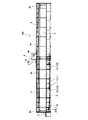
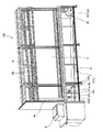
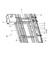
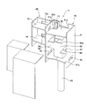
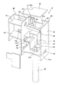
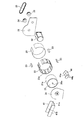
まず、図1〜図3を参照して、本実施の形態に係る遊技球回収装置1が設けられる遊技島100について説明する。図1は遊技島100の内部構造を示す側面図であり、図2は遊技島100の端部付近の内部構造を示す斜視図であり、図3は遊技島100の中央付近の内部構造を示す斜視図である。なお、図1は、遊技島100の左半分の下部化粧板を取り外した状態の図である。   First, with reference to FIGS. 1-3, the game island 100 provided with the game ball collecting apparatus 1 according to the present embodiment will be described. FIG. 1 is a side view showing the internal structure of the game island 100, FIG. 2 is a perspective view showing the internal structure near the end of the game island 100, and FIG. 3 shows the internal structure near the center of the game island 100. It is a perspective view. FIG. 1 is a view showing a state in which the lower decorative plate in the left half of the game island 100 is removed.

遊技島100は、遊技場に設置され、複数の遊技機(図示省略)や付帯設備が設けられるものである。   The amusement island 100 is installed in a game arcade, and is provided with a plurality of gaming machines (not shown) and incidental facilities.

遊技島100は、長手方向(図1においては紙面左右方向)に2列に配列された複数の遊技機設置開口部5を有する。図1においては遊技島100の表面側の遊技機設置開口部5の列のみを図示するが、遊技島100の裏面側にも遊技機設置開口部5の列が形成される。この遊技機設置開口部5には遊技機が設置される。これにより、遊技機は、遊技島100の長手方向に配列されると共に、短手方向(図1においては紙面垂直方向)には、それぞれの背面を合わせた背向状態で配置される。   The gaming island 100 has a plurality of gaming machine installation openings 5 arranged in two rows in the longitudinal direction (left and right direction in FIG. 1). In FIG. 1, only the row of gaming machine installation openings 5 on the front side of the gaming island 100 is illustrated, but the row of gaming machine installation openings 5 is also formed on the back side of the gaming island 100. A gaming machine is installed in the gaming machine installation opening 5. Thereby, the gaming machines are arranged in the longitudinal direction of the gaming island 100, and are arranged in the back direction in which the respective back surfaces are combined in the short side direction (the vertical direction in the drawing in FIG. 1).

遊技島100における遊技機の下方には、各遊技機から排出された遊技球を回収して、回収した遊技球を遊技島100の長手方向略中央に配設された揚送装置3に向けて搬送する遊技球回収装置1が配設される。   Below the gaming machines on the gaming island 100, the gaming balls discharged from each gaming machine are collected, and the collected gaming balls are directed toward the lifting device 3 disposed at the substantially longitudinal center of the gaming island 100. A game ball collecting device 1 to be transported is disposed.

揚送装置3は、遊技球を磨きながら上方へと揚送する装置であり、揚送装置3によって揚送された遊技球は、揚送装置3の上部に設置された上部タンク4へと導かれる。   The lifting device 3 is a device that lifts the game ball upward while polishing the game ball, and the game ball lifted by the lifting device 3 is guided to the upper tank 4 installed at the upper part of the lifting device 3. It is written.

上部タンク4の左右両側には遊技球が排出される排出口4aが配設される。その排出口4aには、上部タンク4の遊技球を、各遊技機及び各遊技機に併設され遊技球を貸し出すための球貸機(図示省略)へと供給する供給樋6が連結される。   Discharge ports 4a through which game balls are discharged are disposed on the left and right sides of the upper tank 4. Connected to the outlet 4a is a supply basket 6 for supplying the game balls in the upper tank 4 to each game machine and a ball lending machine (not shown) for lending game balls.

供給樋6から球貸機へと供給された遊技球は、遊技機における遊技に用いられ、遊技機から排出された遊技球は、遊技球回収装置1に回収されて揚送装置3へ搬送される。   The game balls supplied from the supply basket 6 to the ball lending machine are used for games in the game machine, and the game balls discharged from the game machine are collected by the game ball collecting device 1 and conveyed to the lifting device 3. The

供給樋6から遊技機へと供給された遊技球は、遊技機から賞球として遊技者に対して払い出される。払い出された後、遊技島100の端部に設置された球計数機8に投入された遊技球は、遊技球回収装置1の側方に配設された島端タンク2に導かれる。なお、払い出された遊技球が遊技に用いられることもある。   The game balls supplied from the supply basket 6 to the gaming machine are paid out to the player as prize balls from the gaming machine. After the payout, the game balls thrown into the ball counter 8 installed at the end of the game island 100 are guided to the island end tank 2 disposed on the side of the game ball collection device 1. The game balls that are paid out may be used for games.

また、上部タンク4から供給樋6へと排出されず、上部タンク4をオーバーフローした遊技球は、供給樋6の下方に延在するオーバーフロー樋9aに導かれ、オーバーフローホース9bを通じて島端タンク2へと導かれる。島端タンク2に貯留された遊技球は、島端タンク2に設けられたシャッタ7(図2参照)が開となることによって遊技球回収装置1へと排出されて揚送装置3へと搬送される。   The game balls that have not been discharged from the upper tank 4 to the supply basket 6 and overflowed from the upper tank 4 are guided to an overflow basket 9a that extends below the supply basket 6 and are transferred to the island end tank 2 through the overflow hose 9b. It is guided. The game balls stored in the island-end tank 2 are discharged to the game-ball collecting device 1 when the shutter 7 (see FIG. 2) provided in the island-end tank 2 is opened and transported to the lifting device 3. Is done.

以上のように、遊技島100内の遊技球は、遊技島100内を循環する。   As described above, the game balls in the game island 100 circulate in the game island 100.

なお、遊技島100は、長手方向略中央に配設された揚送装置3及び上部タンク4を中心に左右対称に構成される。つまり、遊技球回収装置1、島端タンク2、供給樋6、オーバーフロー樋9a、及びオーバーフローホース9b等は、揚送装置3及び上部タンク4を中心に左右に1つずつ設けられる。なお、球計数機8のみ遊技島100の一方(本実施の形態では図1中左側)に設けられる。   The amusement island 100 is configured symmetrically with the lifting device 3 and the upper tank 4 disposed approximately in the center in the longitudinal direction. That is, the game ball collecting device 1, the island end tank 2, the supply rod 6, the overflow rod 9 a, the overflow hose 9 b and the like are provided one by one on the left and right with the lifting device 3 and the upper tank 4 as the center. Only the ball counter 8 is provided on one of the game islands 100 (the left side in FIG. 1 in this embodiment).

次に、遊技島100の各構成について詳しく説明する。   Next, each structure of the game island 100 will be described in detail.

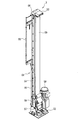
まず、図4を参照して、揚送装置3について説明する。図4は揚送装置3の斜視図である。   First, the lifting device 3 will be described with reference to FIG. FIG. 4 is a perspective view of the lifting device 3.

揚送装置3は、無端ベルト50の循環によって、筺体51下部の導入口52から、筺体51上部の排出口53まで遊技球を揚送し、上部タンク4に供給するものである。   With the circulation of the endless belt 50, the lifting device 3 lifts the game ball from the introduction port 52 at the bottom of the housing 51 to the discharge port 53 at the top of the housing 51, and supplies it to the upper tank 4.

筺体51は、筺体本体54と、筺体本体54の前面開口にヒンジを介して開閉可能に取り付けられる上下2枚の蓋部材55とからなる。   The casing 51 includes a casing main body 54 and two upper and lower lid members 55 attached to the front opening of the casing main body 54 through a hinge so as to be opened and closed.

無端ベルト50は、筺体本体54の上下に配設された従動ローラ56と駆動ローラ57に掛け渡される。駆動ローラ57には減速機付き揚送モータ58が接続され、この揚送モータ58の駆動によって無端ベルト50は循環する。無端ベルト50には、テンションローラ59によって適切なテンションが付与される。   The endless belt 50 is stretched between a driven roller 56 and a driving roller 57 disposed above and below the housing body 54. The drive roller 57 is connected to a feed motor 58 with a speed reducer, and the endless belt 50 circulates by driving the feed motor 58. Appropriate tension is applied to the endless belt 50 by a tension roller 59.

蓋部材55の内側には研磨布(図示省略)が敷設され、研磨布の上下両端部は、それぞれ蓋部材55上下両端で折り返され固定される。   A polishing cloth (not shown) is laid inside the lid member 55, and the upper and lower ends of the polishing cloth are folded and fixed at the upper and lower ends of the lid member 55, respectively.

揚送装置3は以上のように構成され、無端ベルト50が循環している状態で、導入口52に導かれた遊技球は、無端ベルト50との摩擦によって無端ベルト50と研磨布の間に引き込まれ、上方へ揚送される。この揚送過程で、遊技球は研磨布によって自動的に磨かれる。   The lifting device 3 is configured as described above, and the game ball guided to the introduction port 52 in a state where the endless belt 50 is circulated is caused between the endless belt 50 and the polishing cloth by friction with the endless belt 50. It is drawn in and lifted upward. In this lifting process, the game ball is automatically polished by the polishing cloth.

次に、図5及び図6を参照して、上部タンク4について説明する。図5は上部タンク4の内部の斜視図であり、図6は上部タンク4の内部の分解斜視図である。   Next, the upper tank 4 will be described with reference to FIGS. 5 and 6. FIG. 5 is a perspective view of the inside of the upper tank 4, and FIG. 6 is an exploded perspective view of the inside of the upper tank 4.

上部タンク4は、揚送装置3から揚送された遊技球が導かれる上部主タンク4Aと、上部主タンク4Aに併設され、隣接する遊技島間を連絡する島間樋(図示省略)に連通する上部補助タンク4Bとからなる。   The upper tank 4 is an upper main tank 4A through which the game balls lifted from the lifting device 3 are guided, and an upper part connected to the upper main tank 4A and connected to an island between islands (not shown) connecting adjacent game islands. It consists of an auxiliary tank 4B.

上部主タンク4Aの筺体61の上部には、揚送装置3の排出口53に連通する開口部61aが形成され、その開口部61aを通じて上部主タンク4Aの内部に遊技球が導かれる。   In the upper part of the housing 61 of the upper main tank 4A, an opening 61a communicating with the discharge port 53 of the lifting device 3 is formed, and the game ball is guided into the upper main tank 4A through the opening 61a.

開口部61aを通じて上部主タンク4A内へ流入した遊技球は、傾斜して設けられた傾斜板62上に導かれる。傾斜板62には開口部62aが形成され、傾斜板62を下った遊技球は、開口部62a(図5参照)を通じて下方へ流下する。また、筺体61には、傾斜板62を下った遊技球が通過可能であり、上部補助タンク4Bに連通する開口部61bが形成される。このように、傾斜板62上の遊技球は、開口部62aから下方へ流下するか、又は開口部61bを通じて併設された上部補助タンク4Bへと導かれる。   The game ball that has flowed into the upper main tank 4A through the opening 61a is guided onto an inclined plate 62 provided to be inclined. An opening 62a is formed in the inclined plate 62, and the game ball descending the inclined plate 62 flows downward through the opening 62a (see FIG. 5). In addition, the housing 61 is formed with an opening 61b through which a game ball descending the inclined plate 62 can pass and communicates with the upper auxiliary tank 4B. As described above, the game ball on the inclined plate 62 flows downward from the opening 62a or is guided to the upper auxiliary tank 4B provided side by side through the opening 61b.

傾斜板62の開口部62aから下方へ流下した遊技球は、傾斜板62とは逆方向へと傾斜して形成された傾斜樋63(図6参照)に導かれる。傾斜樋63は、一側が筺体61の内壁に接して形成され、傾斜樋63の他側には遊技球の落下を防止するための立壁63aが形成される。したがって、傾斜樋63に導かれた遊技球は、筺体61の内壁と立壁63aとによって区画された流路を転動する。傾斜樋63の下流端部と筺体61の内壁との間には隙間64が存在するため、傾斜樋63を転動した遊技球は、隙間64から下方へと流下する。   The game ball that has flowed downward from the opening 62a of the inclined plate 62 is guided to an inclined rod 63 (see FIG. 6) formed to be inclined in the opposite direction to the inclined plate 62. The inclined rod 63 is formed so that one side is in contact with the inner wall of the housing 61, and a standing wall 63 a for preventing the game ball from falling is formed on the other side of the inclined rod 63. Therefore, the game ball guided to the tilted cage 63 rolls on the flow path defined by the inner wall of the chassis 61 and the standing wall 63a. Since there is a gap 64 between the downstream end portion of the inclined rod 63 and the inner wall of the casing 61, the game ball rolling on the inclined rod 63 flows downward from the gap 64.

傾斜樋63の下方には、上部主タンク4Aの底部61cに立設するオーバーフロー導入塔65が位置する。オーバーフロー導入塔65は、中空状の部材であり、図6に示すように、底部61cに形成された開口部61dを通じてオーバーフロー樋9aに連通する連絡管66に連通している。オーバーフロー導入塔65の側壁上部には、遊技球が流入する導入口65a(図5参照)が形成される。   Below the inclined trough 63, an overflow introduction tower 65 standing on the bottom 61c of the upper main tank 4A is located. The overflow introduction tower 65 is a hollow member and communicates with a connecting pipe 66 that communicates with the overflow rod 9a through an opening 61d formed in the bottom 61c, as shown in FIG. In the upper part of the side wall of the overflow introduction tower 65, an introduction port 65a (see FIG. 5) through which game balls flow is formed.

傾斜樋63から下方へ流下した遊技球は、オーバーフロー導入塔65の側壁と筺体61の内壁との間を流下して第1棚部67上に落下し、第1棚部67に連接された第2棚部68から底部61cに流下する。   The game ball that has flowed downward from the inclined cage 63 flows down between the side wall of the overflow introduction tower 65 and the inner wall of the chassis 61, falls onto the first shelf 67, and is connected to the first shelf 67. The two shelves 68 flow down to the bottom 61c.

底部61cは、中央部から筺体61に形成された左右の排出口4aに向けて下り傾斜して形成される。第2棚部68は、流下する遊技球が底部61cの中央部付近に落下するような傾斜に形成される。したがって、第2棚部68から底部61cへと落下した遊技球は、底部61cの傾斜によって左右に振り分けられ、左右の排出口4aから供給樋6に導かれる。   The bottom portion 61c is formed to be inclined downward from the central portion toward the left and right discharge ports 4a formed in the housing 61. The second shelf 68 is formed with an inclination such that the flowing game ball falls near the center of the bottom 61c. Therefore, the game balls dropped from the second shelf 68 to the bottom 61c are distributed to the left and right by the inclination of the bottom 61c, and are guided to the supply basket 6 from the left and right discharge ports 4a.

このようにして、揚送装置3から上部主タンク4Aに導かれた遊技球は、底部61cまで流下した後、左右の排出口4aから供給樋6に導かれる。   In this way, the game ball guided from the lifting device 3 to the upper main tank 4A flows down to the bottom 61c, and is then guided from the left and right discharge ports 4a to the supply basket 6.

遊技機の稼働率が少ないような場合には、底部61c上に遊技球が堆積し、上部主タンク4A内の遊技球貯留量が増加する。遊技球貯留量が増加し、オーバーフロー導入塔65の導入口65aの位置まで遊技球が貯留されると、導入口65aからオーバーフロー導入塔65内へ遊技球が流入する。このように、上部主タンク4A内の遊技球貯留量が所定量に達すると、オーバーフロー導入塔65からオーバーフローするようになっている。   When the operating rate of the gaming machine is small, gaming balls accumulate on the bottom 61c, and the amount of gaming balls stored in the upper main tank 4A increases. When the game ball storage amount increases and the game ball is stored up to the position of the introduction port 65a of the overflow introduction tower 65, the game ball flows into the overflow introduction tower 65 from the introduction port 65a. In this manner, when the amount of game balls stored in the upper main tank 4A reaches a predetermined amount, the overflow introduction tower 65 overflows.

オーバーフロー導入塔65へ流入した遊技球は、連絡管66から左右のオーバーフロー樋9aの分岐部70(図1参照)に達する。左右のオーバーフロー樋9aは、分岐部70を中心に左右に下り傾斜して形成されるため、連絡管66から分岐部70に達した遊技球は、分岐部70にて左右に振り分けられ、オーバーフロー樋9aを転動する。   The game balls that have flowed into the overflow introduction tower 65 reach the branch portions 70 (see FIG. 1) of the left and right overflow rods 9a from the connecting pipe 66. Since the left and right overflow baskets 9a are formed to be inclined downward to the left and right around the branch part 70, the game balls that have reached the branch part 70 from the connecting pipe 66 are distributed to the left and right at the branch part 70, and the overflow baskets 9a. Roll 9a.

筺体61における傾斜板62の開口部62a近傍には、リミットスイッチ71が設けられる。リミットスイッチ71は、上部主タンク4A内の遊技球貯留量が増加し、リミットスイッチ71の位置まで達するとオンとなる。   A limit switch 71 is provided in the vicinity of the opening 62 a of the inclined plate 62 in the housing 61. The limit switch 71 is turned on when the amount of game balls stored in the upper main tank 4A increases and reaches the position of the limit switch 71.

上部補助タンク4Bは、内部が上室73と下室74に区画されている。上室73は、隣接する遊技島に送球するための送球室であり、上述したように、開口部61bを通じて上部主タンク4Aから遊技球が導かれる。下室74は、隣接する遊技島からの遊技球が流入する受球室である。下室74は、筺体61に形成された開口部61e(図6参照)、及び開口部61eに連通する連通樋69を通じてオーバーフロー導入塔65に連通しており、下室74に流入した遊技球は、オーバーフロー樋9aを経由して、下部タンク2に導かれる。上室73及び下室74のそれぞれには、隣接する遊技島とをつなぐ島間樋が連通する開口部73a及び74aが形成される。   The upper auxiliary tank 4B is partitioned into an upper chamber 73 and a lower chamber 74. The upper chamber 73 is a pitching chamber for sending a ball to the adjacent game island, and as described above, the game ball is guided from the upper main tank 4A through the opening 61b. The lower chamber 74 is a ball receiving chamber into which game balls from adjacent game islands flow. The lower chamber 74 communicates with the overflow introduction tower 65 through an opening 61e (see FIG. 6) formed in the housing 61 and a communication rod 69 communicating with the opening 61e. Then, it is led to the lower tank 2 via the overflow trough 9a. Each of the upper chamber 73 and the lower chamber 74 is formed with openings 73a and 74a through which islands connecting the adjacent game islands communicate.

供給樋6は、上部主タンク4Aから導かれた遊技球を、各遊技機及び各遊技機に併設された球貸機に補給するものである。供給樋6は、上部タンク4から遊技島100の端部に向かって下り傾斜して配設され、傾斜によって遊技球を搬送する。供給樋6には、長手方向に沿って、各遊技機及び各球貸機に対応した補給シュート(図示省略)が複数配設され、その補給シュートを通じて遊技球が補給される。   The supply basket 6 replenishes the gaming balls guided from the upper main tank 4A to each gaming machine and a ball lending machine attached to each gaming machine. The supply basket 6 is disposed so as to be inclined downward from the upper tank 4 toward the end of the game island 100, and conveys game balls by the inclination. A plurality of supply chutes (not shown) corresponding to each gaming machine and each ball lending machine are arranged in the supply basket 6 along the longitudinal direction, and game balls are supplied through the supply chutes.

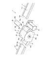
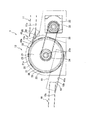
次に、図1〜図3、及び図7〜図9を参照して、遊技球回収装置1及び島端タンク2について説明する。図7は遊技球回収装置1の要部分解斜視図であり、図8は遊技球回収装置1の要部側面図であり、図9は遊技球回収装置1における搬送装置の分解斜視図である。   Next, with reference to FIGS. 1-3 and FIGS. 7-9, the game ball collection | recovery apparatus 1 and the island edge tank 2 are demonstrated. FIG. 7 is an exploded perspective view of the main part of the game ball collecting apparatus 1, FIG. 8 is a side view of the main part of the game ball collecting apparatus 1, and FIG. 9 is an exploded perspective view of the transfer device in the game ball collecting apparatus 1. .

遊技球回収装置1は、各遊技機から排出された遊技球を回収して、回収した遊技球を揚送装置3に向けて搬送する装置である。   The game ball collecting device 1 is a device that collects the game balls discharged from each gaming machine and conveys the collected game balls toward the lifting device 3.

遊技球回収装置1は、遊技島100の長手方向に傾斜して配設され、各遊技機から排出された遊技球を回収する第一回収樋10と、遊技島100の長手方向に傾斜して配設され上流端部11aが第一回収樋10の下流端部10bよりも高い位置に設けられ、各遊技機から排出された遊技球を回収する第二回収樋11と、第一回収樋10から排出された遊技球を第二回収樋11へと搬送する搬送装置12とを備える。   The game ball collecting device 1 is arranged to be inclined in the longitudinal direction of the game island 100, and the first collection basket 10 that collects the game balls discharged from each gaming machine and the game island 100 to be inclined in the longitudinal direction. A second recovery rod 11 that is disposed and is provided at a position where the upstream end portion 11a is higher than the downstream end portion 10b of the first recovery rod 10 and collects game balls discharged from each gaming machine, and the first recovery rod 10 And a transporting device 12 for transporting the game balls discharged from the second recovery basket 11.

第一回収樋10及び第二回収樋11は、遊技球が転動可能な傾斜角度で、かつ双方とも揚送装置3側に向かって傾斜して形成される。   The first recovery rod 10 and the second recovery rod 11 are formed at an inclination angle at which the game ball can roll, and both are inclined toward the lifting device 3 side.

搬送装置12は、第一回収樋10の下流端部10bと第二回収樋11の上流端部11aとの間に配設され、第一回収樋10と第二回収樋11を連結する。   The conveying device 12 is disposed between the downstream end portion 10 b of the first recovery rod 10 and the upstream end portion 11 a of the second recovery rod 11, and connects the first recovery rod 10 and the second recovery rod 11.

遊技球回収装置1は、搬送装置12を少なくとも1つ備える。遊技球回収装置1が搬送装置12を複数備える場合には、隣り合う搬送装置12は回収樋を共有する。本実施の形態では、図1に示すように、搬送装置12は、第一搬送装置12Aと第二搬送装置12Bの2つであり、両者が共有する回収樋は、第一搬送装置12Aから見れば第二回収樋11であり、第二搬送装置12Bから見れば第一回収樋10となる。   The game ball collection device 1 includes at least one transport device 12. When the game ball collection device 1 includes a plurality of transfer devices 12, the adjacent transfer devices 12 share a collection basket. In the present embodiment, as shown in FIG. 1, the transport device 12 includes two transport devices, a first transport device 12A and a second transport device 12B, and the recovery basket shared by both can be seen from the first transport device 12A. The second recovery basket 11 and the first recovery basket 10 when viewed from the second transport device 12B.

第一搬送装置12Aに連通する第一回収樋10は、上流端部10a(図2参照)が島端タンク2のシャッタ7に連通して配設される。また、第二搬送装置12Bに連通する第二回収樋11は、下流端部11b(図3参照)が揚送装置3に遊技球を導く排出樋87に連通して配設される。   The first recovery rod 10 that communicates with the first transport device 12 </ b> A is arranged such that the upstream end portion 10 a (see FIG. 2) communicates with the shutter 7 of the island end tank 2. In addition, the second collection basket 11 that communicates with the second transport device 12B is disposed such that the downstream end portion 11b (see FIG. 3) communicates with a discharge basket 87 that guides the game ball to the lifting device 3.

したがって、島端タンク2から排出された遊技球は、第一搬送装置12Aと第二搬送装置12Bを経て、排出樋87を通じて揚送装置3へと搬送される。   Therefore, the game balls discharged from the island tank 2 are transferred to the lifting device 3 through the discharge rod 87 through the first transfer device 12A and the second transfer device 12B.

また、遊技機から排出され、第一搬送装置12Aに連通する第一回収樋10に回収された遊技球は、同様に、第一搬送装置12Aと第二搬送装置12Bを経て、排出樋87を通じて揚送装置3へと搬送される。このように、排出樋87は、遊技球回収装置1にて回収した遊技球を揚送装置3へと搬送するものであり、遊技機から排出された遊技球を回収する機能は有さない。   In addition, the game balls discharged from the gaming machine and collected in the first collection basket 10 communicating with the first conveyance apparatus 12A are similarly passed through the first conveyance apparatus 12A and the second conveyance apparatus 12B through the discharge basket 87. It is conveyed to the lifting device 3. Thus, the discharge rod 87 conveys the game ball collected by the game ball collection device 1 to the lifting device 3, and does not have a function of collecting the game ball discharged from the game machine.

また、遊技機から排出され、第一搬送装置12Aに連通する第二回収樋11(第二搬送装置12Bから見れば第一回収樋10)に回収された遊技球は、第二搬送装置12Bを経て、排出樋87を通じて揚送装置3へと搬送される。   In addition, the game balls discharged from the gaming machine and collected in the second collection basket 11 (first collection basket 10 as viewed from the second conveyance apparatus 12B) communicating with the first conveyance apparatus 12A are transferred to the second conveyance apparatus 12B. Then, it is conveyed to the lifting device 3 through the discharge rod 87.

図3に示すように、複数の搬送装置12のうち最下流に配設された第二搬送装置12Bに連通する第二回収樋11には、第二回収樋11における遊技球の滞留状態を検出する回収球検出器84(回収球検出手段)が設けられる。具体的には、回収球検出器84は、第二回収樋11と排出樋87の連通部に設けられる。回収球検出器84は、遊技球の磁場によってオンとなるセンサであり、排出樋87が遊技球で満たされ、遊技球が回収球検出器84の位置まで滞留するとオンとなる。   As shown in FIG. 3, the second collection basket 11 communicating with the second conveyance apparatus 12 </ b> B arranged at the most downstream among the plurality of conveyance apparatuses 12 detects the staying state of the game balls in the second collection basket 11. A recovery ball detector 84 (recovered ball detection means) is provided. Specifically, the collection ball detector 84 is provided at a communication portion between the second collection basket 11 and the discharge basket 87. The collection ball detector 84 is a sensor that is turned on by the magnetic field of the game ball, and is turned on when the discharge rod 87 is filled with the game ball and the game ball stays at the position of the collection ball detector 84.

なお、排出樋87を設けずに、第二搬送装置12Bに連通する第二回収樋11を揚送装置3に直接連通させるようにしてもよい。この場合には、回収球検出器84は、第二回収樋11の途中に設けるようにすればよい。   In addition, you may make it make the 2nd recovery rod 11 connected to the 2nd conveying apparatus 12B communicate with the lifting apparatus 3 directly, without providing the discharge rod 87. FIG. In this case, the collection ball detector 84 may be provided in the middle of the second collection basket 11.

図2に示すように、島端タンク2は、遊技島100の左右両端部に配設され、仕切板88を境にして第一回収樋10と仕切られる。仕切板88にはシャッタ7が設けられる。島端タンク2の底部は、第一回収樋10の転動面10cと一体であり、傾斜して形成される。したがって、シャッタ7が閉じている場合には、オーバーフローホース9bから排出された遊技球は島端タンク2に貯留されるが、シャッタ7が開くと、島端タンク2に貯留された遊技球は、底部の傾斜によってシャッタ7を通過し第一回収樋10へと排出されることになる。   As shown in FIG. 2, the island end tank 2 is disposed at both left and right ends of the game island 100, and is partitioned from the first collection basket 10 with the partition plate 88 as a boundary. The partition plate 88 is provided with a shutter 7. The bottom of the island end tank 2 is integral with the rolling surface 10c of the first recovery rod 10, and is formed to be inclined. Therefore, when the shutter 7 is closed, the game ball discharged from the overflow hose 9b is stored in the island end tank 2, but when the shutter 7 is opened, the game ball stored in the island end tank 2 is It passes through the shutter 7 due to the inclination of the bottom, and is discharged to the first recovery rod 10.

島端タンク2の内壁には、遊技島100の長手方向に所定間隔を空けて、島端タンク2における遊技球の貯留状態を検出する貯留球検出器81(81a,81b)(貯留球検出手段)が複数設けられる。貯留球検出器81は、遊技球の磁場によってオンとなるセンサであり、島端タンク2の遊技球貯留量が増加すると、島端タンク2の低所側に配設された貯留球検出器81aから順番にオンとなる。つまり、島端タンク2の遊技球貯留量が増加すると、貯留球検出器81のオンの数が増加する。   A storage ball detector 81 (81a, 81b) (reserved ball detection means) that detects a storage state of game balls in the island end tank 2 at a predetermined interval in the longitudinal direction of the game island 100 on the inner wall of the island end tank 2 ) Are provided. The storage ball detector 81 is a sensor that is turned on by the magnetic field of the game ball, and when the amount of game ball storage in the island end tank 2 increases, the storage ball detector 81a disposed on the low side of the island end tank 2 Turns on in order. That is, when the amount of game balls stored in the island edge tank 2 increases, the number of ON of the stored ball detector 81 increases.

以下では、主に図7〜図9を参照して、遊技球回収装置1の搬送装置12について説明する。   Below, mainly with reference to Drawing 7-Drawing 9, conveyance device 12 of game ball recovery device 1 is explained.

搬送装置12は、遊技島100の短手方向に延びる回転軸20aを中心に回転する回転体20を備え、回転体20の外周縁に配設された磁性体の磁力によって遊技球を回転体20の外周面に吸着させて搬送するものである。ここで、回転体20の外周縁とは、回転体20の外周面と、その外周面よりも小径な円とで囲まれた環状領域のことを指す。   The transport device 12 includes a rotating body 20 that rotates around a rotating shaft 20a extending in the short direction of the gaming island 100, and the game ball is transferred to the rotating body 20 by the magnetic force of the magnetic body disposed on the outer peripheral edge of the rotating body 20. It is made to adsorb | suck to the outer peripheral surface of and convey. Here, the outer peripheral edge of the rotating body 20 refers to an annular region surrounded by the outer peripheral surface of the rotating body 20 and a circle having a smaller diameter than the outer peripheral surface.

回転体20の回転軸20aの両端部は、遊技島100に取り付けられた一対の支持板31によって回転自在に支持される。   Both ends of the rotating shaft 20 a of the rotating body 20 are rotatably supported by a pair of support plates 31 attached to the game island 100.

支持板31の外径は、回転体20の外径よりも大きいため、支持板31の外周縁は、回転体20の外周面に吸着して搬送される遊技球の落下防止用のガイド部として機能する。   Since the outer diameter of the support plate 31 is larger than the outer diameter of the rotating body 20, the outer peripheral edge of the support plate 31 serves as a guide portion for preventing the fall of the game ball that is attracted to the outer peripheral surface of the rotating body 20 and conveyed. Function.

一対の支持板31の一方には、回転体20を回転駆動するための駆動モータ32が固定され、駆動モータ32の出力軸にはプーリ33が固定される。回転体20の回転軸20aにもプーリ34が固定され、プーリ33とプーリ34にはベルト35が掛け回される。   A drive motor 32 for rotating the rotating body 20 is fixed to one of the pair of support plates 31, and a pulley 33 is fixed to the output shaft of the drive motor 32. A pulley 34 is also fixed to the rotating shaft 20 a of the rotating body 20, and a belt 35 is wound around the pulley 33 and the pulley 34.

駆動モータ32が回転駆動することによって、その回転がプーリ33,34及びベルト35を介して回転体20に伝達され、回転体20は回転軸20aを中心に回転する。   When the drive motor 32 is driven to rotate, the rotation is transmitted to the rotary body 20 via the pulleys 33 and 34 and the belt 35, and the rotary body 20 rotates about the rotary shaft 20a.

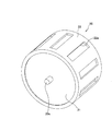
回転体20は、図9に示すように、軸中心に回転軸20aを有するベースドラム21と、ベースドラム21の外周に沿って配設され、磁性体を保持する磁石ガイド22とを備える。   As shown in FIG. 9, the rotating body 20 includes a base drum 21 having a rotating shaft 20 a at the center thereof, and a magnet guide 22 that is disposed along the outer periphery of the base drum 21 and holds the magnetic body.

ベースドラム21は、軟磁性体にて構成された円筒状の胴部21aの両端開口部が閉塞された中空円筒状の部材である。このように、ベースドラム21の外周部は、軟磁性体にて構成される。なお、軟磁性体としては、例えば、SUS430等のフェライト系ステンレス鋼が用いられる。   The base drum 21 is a hollow cylindrical member in which both end openings of a cylindrical body portion 21a made of a soft magnetic material are closed. Thus, the outer peripheral part of the base drum 21 is comprised with a soft magnetic body. As the soft magnetic material, for example, ferritic stainless steel such as SUS430 is used.

磁石ガイド22は、長辺がベースドラム21の外周長さと同等であり、可撓性を有する細長いシート状の部材であり、ベースドラム21の外周に巻き付けられて配設される。磁石ガイド22は、ゴム製であり、非磁性体にて構成される。   The magnet guide 22 is an elongated sheet-like member having a long side equivalent to the outer peripheral length of the base drum 21 and having flexibility, and is wound around the outer periphery of the base drum 21. The magnet guide 22 is made of rubber and is made of a nonmagnetic material.

なお、磁石ガイド22は、非磁性体であれば、常磁性の金属、合成樹脂、又はセラミックス製でもよく、その場合、磁石ガイド22が可撓性を有さない場合には、環状に形成されてベースドラム21の外周に嵌挿される。   The magnet guide 22 may be made of a paramagnetic metal, synthetic resin, or ceramics as long as it is a non-magnetic material. In this case, if the magnet guide 22 is not flexible, it is formed in an annular shape. The base drum 21 is inserted into the outer periphery.

磁石ガイド22には、硬磁性体23を保持する複数の保持部22aが上下面を貫通して形成される。保持部22aは、磁石ガイド22の短手方向に延在し、かつ磁石ガイド22の長手方向に所定間隔を空けて形成される。   In the magnet guide 22, a plurality of holding portions 22 a that hold the hard magnetic body 23 are formed through the upper and lower surfaces. The holding portion 22 a extends in the short direction of the magnet guide 22 and is formed at a predetermined interval in the longitudinal direction of the magnet guide 22.

各保持部22a内には、板状の硬磁性体23がぴったりと装着される。磁石ガイド22がベースドラム21の外周に巻き付けられることによって、各硬磁性体23は、回転軸20a方向に延在し、かつ回転体20周方向に所定間隔を空けて配設される。   A plate-like hard magnetic body 23 is fitted exactly in each holding portion 22a. When the magnet guide 22 is wound around the outer periphery of the base drum 21, each hard magnetic body 23 extends in the direction of the rotating shaft 20 a and is disposed at a predetermined interval in the circumferential direction of the rotating body 20.

磁石ガイド22の外周には、硬磁性体23の脱落を防止するための磁石カバー26が貼り付けられる。磁石カバー26は、内周面に糊等の粘着物を塗布した薄く細長いフィルム状のものである。   A magnet cover 26 for preventing the hard magnetic body 23 from falling off is attached to the outer periphery of the magnet guide 22. The magnet cover 26 is a thin and long film having an inner peripheral surface coated with an adhesive such as glue.

なお、硬磁性体23の脱落を防止するための手段として、磁石カバー26を用いずに、磁石ガイド22に硬磁性体23を係止する構造を設けてもよい。   As a means for preventing the hard magnetic body 23 from falling off, a structure for locking the hard magnetic body 23 to the magnet guide 22 without using the magnet cover 26 may be provided.

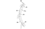
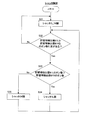
以上のように、ベースドラム21の外周に沿って硬磁性体23を保持した磁石ガイド22が配設されることによって、回転体20の外周縁には、図8に示すように、硬磁性体23が回転体20周方向に所定間隔を空けて配設されると共に、隣り合う硬磁性体23の間にはゴム製の磁石ガイド22を通じて軟磁性体のベースドラム21が臨むことになる。このように、回転体20の外周縁には、硬磁性体23と軟磁性体が、回転体20周方向に交互に配設される。   As described above, by arranging the magnet guide 22 holding the hard magnetic body 23 along the outer periphery of the base drum 21, the hard magnetic body is disposed on the outer peripheral edge of the rotating body 20 as shown in FIG. 23 is arranged at a predetermined interval in the circumferential direction of the rotating body 20, and a soft magnetic base drum 21 faces between the adjacent hard magnetic bodies 23 through a rubber magnet guide 22. As described above, the hard magnetic body 23 and the soft magnetic body are alternately arranged in the circumferential direction of the rotating body 20 on the outer peripheral edge of the rotating body 20.

本明細書において、硬磁性体とは、外部磁場が加わっても磁化しにくく、また、一度磁化したらその残留磁化を強く保つ磁性体をいい、永久磁石を含む。   In this specification, a hard magnetic material is a magnetic material that is difficult to magnetize even when an external magnetic field is applied, and that retains its residual magnetization strongly once magnetized, and includes a permanent magnet.

また、軟磁性体とは、外部磁場に対して磁化が磁場方向に揃いやすく、また、残留磁化の保持力が小さい磁性体をいう。   The soft magnetic material refers to a magnetic material in which magnetization is easily aligned in the magnetic field direction with respect to an external magnetic field, and the retentive force of residual magnetization is small.

また、非磁性体とは、磁界と相互作用を及ぼさないものをいう。   A non-magnetic material means a material that does not interact with a magnetic field.

搬送装置12は、第一回収樋10と回転体20とに亘って配設され第一回収樋10を転動し下流端部10bから排出される遊技球を回転体20へと導く供給ガイド41と、回転体20と第二回収樋11とに亘って配設され回転体20によって搬送された遊技球を第二回収樋11へと導く排出ガイド42とをさらに備える。   The transport device 12 is disposed over the first collection basket 10 and the rotator 20 and rolls the first collection basket 10 to guide the game ball discharged from the downstream end 10 b to the rotator 20. And a discharge guide 42 that is disposed between the rotating body 20 and the second collection basket 11 and that guides the game balls conveyed by the rotating body 20 to the second collection basket 11.

供給ガイド41は、遊技球が転動する転動面41aと、転動面41aの両側に立設して設けられ遊技球の落下を防止するためのガイド壁41bとからなるコの字状の部材であり、非磁性体にて構成される。   The supply guide 41 is formed in a U-shape comprising a rolling surface 41a on which the game ball rolls and a guide wall 41b provided on both sides of the rolling surface 41a to prevent the game ball from falling. It is a member and is composed of a non-magnetic material.

第一回収樋10は、下流端部10bが供給ガイド41内に挿入されて、供給ガイド41と連通する。   The downstream end portion 10 b of the first recovery rod 10 is inserted into the supply guide 41 and communicates with the supply guide 41.

供給ガイド41の転動面41aは、第一回収樋10の遊技球が転動する転動面10cと比較して傾斜が大きい。   The rolling surface 41a of the supply guide 41 has a larger inclination than the rolling surface 10c on which the game balls of the first recovery basket 10 roll.

第一回収樋10と供給ガイド41は、転動面10cと転動面41aが遊技球1個分以上の段差43をもって接続される。つまり、第一回収樋10の下流端部10bと供給ガイド41の転動面41aとの間には、遊技球1個分以上の段差43が設けられる。これにより、第一回収樋10の下流端部10bから排出された遊技球は、段差43を落下して供給ガイド41の転動面41aに導かれる。   The first recovery basket 10 and the supply guide 41 are connected to each other with a step 43 having a rolling surface 10c and a rolling surface 41a corresponding to one or more game balls. That is, a step 43 equal to or more than one game ball is provided between the downstream end portion 10 b of the first recovery basket 10 and the rolling surface 41 a of the supply guide 41. Thereby, the game ball discharged from the downstream end portion 10 b of the first recovery basket 10 falls down the step 43 and is guided to the rolling surface 41 a of the supply guide 41.

供給ガイド41の転動面41aの下流側は、回転体20の外周面と遊技球が通過不能な隙間をもって対峙する。これにより、供給ガイド41に導かれるゴミ等の異物のみが、転動面41aと回転体20の外周面との間を通過するため、供給ガイド41を転動する遊技球の落下を防止しつつ、供給ガイド41に導かれる異物を回収することができる。   The downstream side of the rolling surface 41a of the supply guide 41 faces the outer peripheral surface of the rotating body 20 with a gap through which the game ball cannot pass. As a result, only foreign matters such as dust guided to the supply guide 41 pass between the rolling surface 41a and the outer peripheral surface of the rotating body 20, so that the game ball rolling on the supply guide 41 is prevented from falling. The foreign matter guided to the supply guide 41 can be collected.

排出ガイド42は、底部44aと底部44aの両側に立設して設けられ遊技球の落下を防止するためのガイド壁44bとからなるコの字状のガイド部材44と、ガイド部材44内に配設され、回転体20の外周面に吸着した遊技球を第二回収樋11へと導くガイド板45とからなる。ガイド部材44及びガイド板45は、非磁性体にて構成される。   The discharge guide 42 is disposed in the guide member 44 and a U-shaped guide member 44 that is provided standing on both sides of the bottom portion 44 a and a guide wall 44 b for preventing the game ball from dropping. And a guide plate 45 that guides the game ball adsorbed on the outer peripheral surface of the rotating body 20 to the second recovery basket 11. The guide member 44 and the guide plate 45 are made of a nonmagnetic material.

第二回収樋11は、上流端部11aがガイド部材44内に挿入されて、ガイド部材44と連通する。また、ガイド板45は、下流端部45cが第二回収樋11に挿入されて、第二回収樋11と連通する。   The second recovery rod 11 communicates with the guide member 44 by inserting the upstream end portion 11 a into the guide member 44. Further, the guide plate 45 communicates with the second recovery rod 11 by inserting the downstream end 45 c into the second recovery rod 11.

ガイド板45の転動面45aは、第二回収樋11の遊技球が転動する転動面11cと比較して傾斜が大きい。   The rolling surface 45a of the guide plate 45 is larger in inclination than the rolling surface 11c on which the game balls of the second recovery rod 11 roll.

ガイド板45の転動面45aの上流端部には、ガイド部材44の底部44aの端部に係止されると共に、回転体20の外周面に摺接する円柱状のガイドロッド45bが形成される。ガイドロッド45bは、回転体20外周面の幅方向全体に亘って形成される。   At the upstream end of the rolling surface 45 a of the guide plate 45, a cylindrical guide rod 45 b is formed that is engaged with the end of the bottom 44 a of the guide member 44 and that is in sliding contact with the outer peripheral surface of the rotating body 20. . The guide rod 45b is formed over the entire width direction of the outer peripheral surface of the rotating body 20.

回転体20の回転に伴って回転体20の外周面とガイドロッド45bとは摺接するが、ガイドロッド45bの外周形状は円形であるため、両者間に発生する摩擦は小さい。   As the rotating body 20 rotates, the outer peripheral surface of the rotating body 20 and the guide rod 45b are in sliding contact with each other. However, since the outer peripheral shape of the guide rod 45b is circular, the friction generated between the two is small.

回転体20の外周面に吸着して搬送される遊技球は、ガイドロッド45bに当接することによって、回転体20の外周面から離れてガイド板45の転動面45aに導かれる。ガイドロッド45bの外周形状は円形であるため、回転体20の外周面に吸着して搬送される遊技球は、ガイドロッド45bの外周形状に沿って滑らかにガイド板45に導かれる。   The game balls that are attracted to and transported by the outer peripheral surface of the rotating body 20 are guided away from the outer peripheral surface of the rotating body 20 to the rolling surface 45a of the guide plate 45 by contacting the guide rod 45b. Since the outer peripheral shape of the guide rod 45b is circular, the game ball attracted to and transported by the outer peripheral surface of the rotating body 20 is smoothly guided to the guide plate 45 along the outer peripheral shape of the guide rod 45b.

ガイド板45の転動面45aの下流端部45cは、第二回収樋11の転動面11cに連接する。このため、ガイド板45を転動する遊技球は、スムーズに第二回収樋11へと導かれる。なお、ガイド板45に代わり、ガイド部材44の底部44aと第二回収樋11の転動面11cとに亘りガムテープを貼り付け、双方をガムテープを介して滑らかに接続するようにしてもよい。   A downstream end 45 c of the rolling surface 45 a of the guide plate 45 is connected to the rolling surface 11 c of the second recovery rod 11. For this reason, the game ball rolling on the guide plate 45 is smoothly guided to the second collection basket 11. Instead of the guide plate 45, a gum tape may be applied across the bottom 44a of the guide member 44 and the rolling surface 11c of the second recovery rod 11, and both may be smoothly connected via the gum tape.

以上のように、第一回収樋10と第二回収樋11は、第二回収樋11の上流端部11aが第一回収樋10の下流端部10bよりも高い位置となるように配設され、第一回収樋10から供給ガイド41を通じて回転体20に導かれた遊技球は、磁力によって回転体20の外周面に吸着し、回転体20の回転によって第二回収樋11に連通する排出ガイド42まで搬送される。   As described above, the first recovery rod 10 and the second recovery rod 11 are arranged such that the upstream end portion 11a of the second recovery rod 11 is positioned higher than the downstream end portion 10b of the first recovery rod 10. The game ball guided from the first recovery basket 10 to the rotating body 20 through the supply guide 41 is attracted to the outer peripheral surface of the rotating body 20 by magnetic force, and the discharge guide communicates with the second recovery basket 11 by the rotation of the rotating body 20. 42 is conveyed.

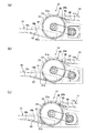
次に、主に、図8及び図10〜図13を参照して、遊技球回収装置1の動作について説明する。図10は搬送装置12によって遊技球が搬送される過程を示す図であり、図11は図10の比較例を示す図であり、図12は遊技球が回転体20の外周面に吸着し搬送されている状態を示す図であり、図13は図12の比較例を示す図である。   Next, the operation of the game ball collecting apparatus 1 will be described mainly with reference to FIGS. 8 and 10 to 13. FIG. 10 is a diagram illustrating a process in which a game ball is transported by the transport device 12, FIG. 11 is a diagram illustrating a comparative example of FIG. 10, and FIG. FIG. 13 is a diagram illustrating a comparative example of FIG. 12.

遊技機から排出された遊技球及び島端タンク2から排出された遊技球は、図10(a),(b)に示すように、第一回収樋10を転動し、第一回収樋10から供給ガイド41を通じて回転体20へと導かれる。   As shown in FIGS. 10A and 10B, the game balls discharged from the gaming machine and the game balls discharged from the island-end tank 2 roll the first collection basket 10 and the first collection basket 10 To the rotating body 20 through the supply guide 41.

ここで、供給ガイド41の転動面41aは、第一回収樋10の転動面10cと比較して傾斜が大きいため、遊技球は供給ガイド41の転動面41a上を勢いよく転動する。そのため、図10(b)に示すように、転動面41a上に遊技球が連なった状態になっても、後から供給ガイド41へと排出される遊技球は、その連なった遊技球に乗り上げて遊技球上を転動するため、回転体20の外周面近傍まで到達し易い。   Here, since the rolling surface 41 a of the supply guide 41 has a larger inclination than the rolling surface 10 c of the first recovery rod 10, the game ball rolls vigorously on the rolling surface 41 a of the supply guide 41. . Therefore, as shown in FIG. 10 (b), even if the game balls are in a continuous state on the rolling surface 41a, the game balls that are subsequently discharged to the supply guide 41 ride on the continuous game balls. Therefore, since it rolls on the game ball, it can easily reach the vicinity of the outer peripheral surface of the rotating body 20.

これに対して、図11(a)に示すように、供給ガイド41の転動面41aの傾斜が、第一回収樋10の転動面10cの傾斜と比較して同等又は小さい場合には、供給ガイド41を転動する遊技球の勢いが弱いため、後から供給ガイド41へと排出される遊技球は、連なった遊技球上を転動することができず、第一回収樋10と供給ガイド41の接続部近傍に堆積し、回転体20の外周面まで到達し難い。   On the other hand, as shown in FIG. 11A, when the inclination of the rolling surface 41a of the supply guide 41 is equal to or smaller than the inclination of the rolling surface 10c of the first recovery rod 10, Since the momentum of the game balls rolling on the supply guide 41 is weak, the game balls discharged to the supply guide 41 later cannot roll on the connected game balls, and are supplied to the first collection basket 10. It accumulates in the vicinity of the connecting portion of the guide 41 and hardly reaches the outer peripheral surface of the rotating body 20.

また、第一回収樋10の下流端部10bと供給ガイド41の転動面41aとの間には、遊技球1個分以上の段差43が設けられるため、図10(b)に示すように、転動面41a上に遊技球が連なった状態になっても、後から供給ガイド41へと排出される遊技球は、その連なった遊技球上に排出されるため、回転体20の外周面近傍まで到達し易い。   Further, since a step 43 equal to or more than one gaming ball is provided between the downstream end portion 10b of the first recovery basket 10 and the rolling surface 41a of the supply guide 41, as shown in FIG. Even if the game balls are connected to the rolling surface 41a, the game balls discharged to the supply guide 41 later are discharged onto the connected game balls. It is easy to reach the vicinity.

これに対して、図11(b)に示すように、第一回収樋10の下流端部10bと供給ガイド41の転動面41aとの間に段差がなく、双方が滑らかに連通している場合には、遊技球が積み重なり難いため、回転体20の外周面まで到達し難い。   On the other hand, as shown in FIG. 11B, there is no step between the downstream end 10b of the first recovery rod 10 and the rolling surface 41a of the supply guide 41, and both are smoothly communicating. In such a case, it is difficult for the game balls to be stacked, so that it is difficult to reach the outer peripheral surface of the rotating body 20.

以上のように、供給ガイド41の傾斜を大きくし、かつ第一回収樋10との間に段差を設けることによって、図10(c)に示すように、第一回収樋10から排出される遊技球を、供給ガイド41の転動面41aと回転体20の外周面とで囲まれた磁界の影響を受け易い領域へと流れ込ませることができる。これにより、回転体20の外周面近傍の遊技球の個数が多くなるため、磁界の作用によって回転体20の外周面に遊技球が吸着し易くなる。   As described above, by increasing the inclination of the supply guide 41 and providing a step with the first recovery rod 10, the game discharged from the first recovery rod 10 as shown in FIG. The sphere can be caused to flow into a region that is easily influenced by the magnetic field surrounded by the rolling surface 41 a of the supply guide 41 and the outer peripheral surface of the rotating body 20. As a result, the number of game balls in the vicinity of the outer peripheral surface of the rotator 20 increases, so that the game balls are easily attracted to the outer peripheral surface of the rotator 20 by the action of the magnetic field.

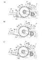
供給ガイド41によって回転体20の外周面近傍まで到達した遊技球は、回転体20の外周縁に配設された硬磁性体23が及ぼす磁界によって、硬磁性体23に吸着する。   The game ball that has reached the vicinity of the outer peripheral surface of the rotating body 20 by the supply guide 41 is attracted to the hard magnetic body 23 by the magnetic field exerted by the hard magnetic body 23 disposed on the outer peripheral edge of the rotating body 20.

硬磁性体23に吸着した遊技球は磁化されるため、その磁化された遊技球に他の遊技球が吸着し磁化される。このようにして、遊技球は、図12に示すように、数珠状に吸着する。   Since the game ball attracted to the hard magnetic body 23 is magnetized, another game ball is attracted and magnetized by the magnetized game ball. In this way, the game balls are adsorbed in a bead shape as shown in FIG.

また、数珠状に吸着した遊技球は磁化されているため、これらの遊技球の磁場によって、軟磁性体であるベースドラム21の胴部21aも磁化される。これにより、数珠状に吸着した遊技球は、磁石ガイド22と磁石カバー26を隔ててベースドラム21の胴部21aに引き寄せられる。このように、硬磁性体23、数珠状に吸着した遊技球、及び軟磁性体の胴部21aによって、回転体20の外周縁には磁気回路が構成されるため、図10(c)及び図12に示すように、遊技球は、各硬磁性体23を基点として、回転体20の外周面に数珠状に吸着する。   Further, since the game balls adsorbed in a bead shape are magnetized, the body portion 21a of the base drum 21 which is a soft magnetic material is also magnetized by the magnetic field of these game balls. As a result, the game balls adsorbed in a bead shape are attracted to the body portion 21 a of the base drum 21 with the magnet guide 22 and the magnet cover 26 therebetween. In this way, a magnetic circuit is formed on the outer peripheral edge of the rotating body 20 by the hard magnetic body 23, the game ball adsorbed in a bead shape, and the body portion 21a of the soft magnetic body. As shown in FIG. 12, the game ball is adsorbed in a rosary shape on the outer peripheral surface of the rotating body 20 with each hard magnetic body 23 as a base point.

ここで、仮に、ベースドラム21の胴部21aが非磁性体である場合には、胴部21aは磁化されないため、回転体20の外周縁に磁気回路が構成されない。この場合には、図13に示すように、遊技球は、硬磁性体23を基点として数珠状には吸着するものの、回転体20の外周面には吸着せず、重力によって鉛直下方へとぶら下がった状態となる。したがって、数珠状に吸着する遊技球の個数には限界があり、多くの遊技球を搬送することができない。また、遊技球の重さによっては落下するため、効率良く遊技球を搬送することができない。   Here, if the body portion 21a of the base drum 21 is a non-magnetic material, the body portion 21a is not magnetized, so that no magnetic circuit is formed on the outer peripheral edge of the rotating body 20. In this case, as shown in FIG. 13, the game ball is adsorbed in a rosary shape with the hard magnetic body 23 as a starting point, but is not adsorbed on the outer peripheral surface of the rotating body 20 and is hung vertically downward by gravity. It becomes a state. Therefore, there is a limit to the number of game balls that are adsorbed in a bead shape, and many game balls cannot be transported. Moreover, since it falls depending on the weight of a game ball, a game ball cannot be conveyed efficiently.

また、仮に、供給ガイド41が軟磁性体である場合には、供給ガイド41内の遊技球が硬磁性体23に吸着した際、硬磁性体23、供給ガイド41内の遊技球、及び供給ガイド41にて磁気回路が構成される。このため、図11(c)に示すように、硬磁性体23と供給ガイド41とに亘って遊技球が連なってしまい、遊技球は、回転体20の外周面に効率良く吸着しない。このことから、供給ガイド41が非磁性体であることは、効率良く遊技球を搬送するための要件となる。供給ガイド41は、例えば、SUS304等のオーステナイト系ステンレス鋼にて構成される。   Further, if the supply guide 41 is a soft magnetic body, when the game ball in the supply guide 41 is attracted to the hard magnetic body 23, the hard magnetic body 23, the game ball in the supply guide 41, and the supply guide At 41, a magnetic circuit is constructed. For this reason, as shown in FIG. 11 (c), the game balls are connected across the hard magnetic body 23 and the supply guide 41, and the game balls are not efficiently attracted to the outer peripheral surface of the rotating body 20. For this reason, the supply guide 41 being a non-magnetic material is a requirement for efficiently transporting game balls. The supply guide 41 is made of, for example, austenitic stainless steel such as SUS304.

供給ガイド41を非磁性体にて構成すると、回転体20と第一回収樋10とは非磁性体によって隔てられることになるため、第一回収樋10を転動する遊技球に対して磁界が及び難い構成となる。そのため、第一回収樋10は、材料選定にあたって制約がなく、コストの面から自由に選定することができる。例えば、SUS304よりも安価であり、軟磁性体であるSUS430にて構成することもできる。   If the supply guide 41 is made of a non-magnetic material, the rotating body 20 and the first recovery rod 10 are separated from each other by a non-magnetic material, so that a magnetic field is applied to the game ball rolling on the first recovery rod 10. And it becomes a difficult structure. Therefore, the first recovery rod 10 is free from restrictions in terms of material selection and can be freely selected from the viewpoint of cost. For example, it is cheaper than SUS304, and can also be composed of SUS430, which is a soft magnetic material.

回転体20の外周面に数珠状に吸着した遊技球は、回転体20の回転に伴って搬送され、図10(c)に示すように、回転体20の外周面に摺接するガイド板45のガイドロッド45bに当接することによって、回転体20の外周面から離れてガイド板45の転動面45aに導かれ、第二回収樋11へと流入する。このようにして、第一回収樋10の下流端部10bから排出された遊技球は、第二回収樋11の上流端部11aへと搬送される。   The game balls adsorbed in a rosary shape on the outer peripheral surface of the rotating body 20 are transported as the rotating body 20 rotates, and the guide plate 45 slidably contacts the outer peripheral surface of the rotating body 20 as shown in FIG. By coming into contact with the guide rod 45 b, it is guided away from the outer peripheral surface of the rotating body 20 to the rolling surface 45 a of the guide plate 45 and flows into the second recovery rod 11. In this way, the game balls discharged from the downstream end portion 10 b of the first collection basket 10 are transported to the upstream end portion 11 a of the second collection basket 11.

次に、図14〜図17を参照して、遊技島100の各装置の動作について説明する。図14は遊技島制御装置101のブロック図であり、図15は揚送装置3の起動停止の流れを示すフローチャートであり、図16は遊技球回収装置1の回転体20の起動停止の流れを示すフローチャートであり、図17は島端タンク2のシャッタ7の開閉動作の流れを示すフローチャートである。   Next, with reference to FIGS. 14-17, operation | movement of each apparatus of the game island 100 is demonstrated. FIG. 14 is a block diagram of the game island control device 101, FIG. 15 is a flowchart showing a flow of starting and stopping the lifting device 3, and FIG. 16 shows a flow of starting and stopping the rotating body 20 of the game ball collecting device 1. FIG. 17 is a flowchart showing the flow of the opening / closing operation of the shutter 7 of the island end tank 2.

まず、図14を参照して、遊技島制御装置101について説明する。   First, the game island control apparatus 101 will be described with reference to FIG.

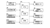
遊技島制御装置101は、遊技島100に設置される各装置の動作を制御するものであり、CPU102、ROM(Read Only Memory)103、及びRAM(Random Access Memory)104を備える。   The amusement island control device 101 controls the operation of each device installed on the amusement island 100, and includes a CPU 102, a ROM (Read Only Memory) 103, and a RAM (Random Access Memory) 104.

CPU102は、遊技島100の動作を統括的に制御するものであり、各種入力装置からの検出信号を受けて、遊技島100の各装置のモータの動作を制御する。具体的には、上部タンク4に設けられたリミットスイッチ71、第二搬送装置12Bの第二回収樋11に設けられた回収球検出器84、及び島端タンク2に設けられた貯留球検出器81からの検出信号を受けて、揚送装置3の揚送モータ58、遊技球回収装置1の回転体20の駆動モータ32、及び島端タンク2のシャッタ7を開閉するシャッタモータ85の動作を制御する。   The CPU 102 comprehensively controls the operation of the game island 100, and receives the detection signals from various input devices and controls the operation of the motor of each device of the game island 100. Specifically, a limit switch 71 provided in the upper tank 4, a collection ball detector 84 provided in the second collection basket 11 of the second transport device 12B, and a storage ball detector provided in the island end tank 2 In response to the detection signal from 81, the operation of the lifting motor 58 of the lifting device 3, the drive motor 32 of the rotating body 20 of the game ball collecting device 1, and the shutter motor 85 that opens and closes the shutter 7 of the island end tank 2 is performed. Control.

なお、上述のように、島端タンク2は、揚送装置3を中心として遊技島100の左右それぞれに配設される。以下において、島端タンク2L、貯留球検出器81L、シャッタ7L、及びシャッタモータ85Lとは、遊技島100の球計数機8側(図1中左側)に配設されるものを指し、島端タンク2R、貯留球検出器81R、シャッタ7R、及びシャッタモータ85Rとは、遊技島100の図1中右側に配設されるものを指す。したがって、島端タンク2Lには、オーバーフローホース9bから排出された遊技球と共に、球計数機8に投入された遊技球が貯留される一方、島端タンク2Rには、オーバーフローホース9bから排出された遊技球のみが貯留される。   In addition, as described above, the island end tank 2 is disposed on each of the left and right sides of the game island 100 with the lifting device 3 as the center. Hereinafter, the island end tank 2L, the stored ball detector 81L, the shutter 7L, and the shutter motor 85L refer to those disposed on the ball counter 8 side (the left side in FIG. 1) of the game island 100. The tank 2R, the stored ball detector 81R, the shutter 7R, and the shutter motor 85R are those disposed on the right side of the game island 100 in FIG. Therefore, while the game balls discharged from the overflow hose 9b are stored in the island end tank 2L, the game balls thrown into the ball counter 8 are stored, while the island end tank 2R is discharged from the overflow hose 9b. Only game balls are stored.

次に、図15を参照して、揚送装置3の動作について説明する。   Next, with reference to FIG. 15, the operation of the lifting device 3 will be described.

まず、ステップ11にて、揚送モータ58が起動する。これにより、遊技球回収装置1によって揚送装置3に搬送された遊技球は、揚送装置3によって上部タンク4へと揚送される。   First, at step 11, the lifting motor 58 is activated. Thereby, the game ball conveyed to the lifting device 3 by the game ball collecting device 1 is lifted to the upper tank 4 by the lifting device 3.

ステップ12では、上部主タンク4Aに設けられたリミットスイッチ71がオンであるか否かが判定される。つまり、上部主タンク4A内の遊技球貯留量がリミットスイッチ71の位置まで達しているかが判定される。判定の結果、リミットスイッチ71がオンであると判定されれば、ステップ13へと進む。   In step 12, it is determined whether or not the limit switch 71 provided in the upper main tank 4A is on. That is, it is determined whether the amount of game balls stored in the upper main tank 4A has reached the position of the limit switch 71. As a result of the determination, if it is determined that the limit switch 71 is on, the process proceeds to step 13.

ステップ13では、揚送モータ58が停止する。これにより、揚送装置3から上部主タンク4Aへの遊技球の供給が停止される。   In step 13, the lifting motor 58 is stopped. Thereby, supply of the game ball from the lifting device 3 to the upper main tank 4A is stopped.

ステップ14では、リミットスイッチ71がオフになったか否かが判定される。つまり、揚送モータ58の停止の結果、上部主タンク4A内の遊技球貯留量が、リミットスイッチ71の位置よりも低くなったかが判定される。   In step 14, it is determined whether or not the limit switch 71 is turned off. That is, it is determined whether the amount of game balls stored in the upper main tank 4 </ b> A has become lower than the position of the limit switch 71 as a result of the stopping of the lifting motor 58.

判定の結果、リミットスイッチ71がオフであると判定されれば、ステップ11へと戻り、揚送モータ58が再び起動する。以降、上記手順を繰り返す。   As a result of the determination, if it is determined that the limit switch 71 is off, the process returns to step 11 and the lifting motor 58 is activated again. Thereafter, the above procedure is repeated.

次に、図16を参照して、遊技球回収装置1の回転体20の動作について説明する。   Next, with reference to FIG. 16, operation | movement of the rotary body 20 of the game ball collection apparatus 1 is demonstrated.

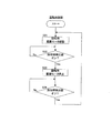
まず、ステップ21にて、第一搬送装置12A及び第二搬送装置12Bの駆動モータ32が起動する。これにより、第一搬送装置12A及び第二搬送装置12Bの回転体20が回転し、遊技機から排出された遊技球、及び島端タンク2から排出された遊技球は、遊技球回収装置1によって揚送装置3に向けて搬送される。   First, in step 21, the drive motors 32 of the first transport device 12A and the second transport device 12B are activated. Thereby, the rotating bodies 20 of the first transfer device 12A and the second transfer device 12B rotate, and the game balls discharged from the gaming machine and the game balls discharged from the island end tank 2 are collected by the game ball collecting device 1. It is conveyed toward the lifting device 3.

ステップ22では、第二搬送装置12Bに連通する第二回収樋11に設けられた回収球検出器84がオンであるか否かが判定される。つまり、第二回収樋11と揚送装置3をつなぐ排出樋87が遊技球で満たされ、第二回収樋11に遊技球が滞留し、遊技球が回収球検出器84の位置まで滞留しているかが判定される。判定の結果、回収球検出器84がオンであると判定されれば、ステップ23へと進む。   In step 22, it is determined whether or not the collection ball detector 84 provided in the second collection basket 11 communicating with the second transport device 12B is on. That is, the discharge rod 87 connecting the second collection rod 11 and the lifting device 3 is filled with game balls, the game balls stay in the second collection rod 11, and the game balls stay up to the position of the collection ball detector 84. Is determined. As a result of the determination, if it is determined that the recovered ball detector 84 is on, the process proceeds to step 23.

ステップ23では、第一搬送装置12A及び第二搬送装置12Bの駆動モータ32が停止する。つまり、遊技球回収装置1の全ての駆動モータ32が停止する。これにより、全ての回転体20の回転が停止し、遊技球回収装置1から揚送装置3への遊技球の搬送が停止される。このように、回転体20は、回収球検出器84の検出状況に応じて停止する。   In step 23, the drive motors 32 of the first transport device 12A and the second transport device 12B are stopped. That is, all the drive motors 32 of the game ball collecting apparatus 1 are stopped. Thereby, rotation of all the rotary bodies 20 stops, and conveyance of the game ball from the game ball collection | recovery apparatus 1 to the raising apparatus 3 is stopped. As described above, the rotating body 20 stops according to the detection status of the collection ball detector 84.

ステップ24では、回収球検出器84がオフになったか否かが判定される。つまり、回転体20の停止の結果、遊技球が回収球検出器84の位置まで滞留していないかが判定される。   In step 24, it is determined whether or not the collection ball detector 84 is turned off. That is, as a result of the stop of the rotating body 20, it is determined whether or not the game ball stays at the position of the collected ball detector 84.

判定の結果、回収球検出器84がオフであると判定されれば、ステップ21へと戻り、第一搬送装置12A及び第二搬送装置12Bの駆動モータ32が再び起動し、回転体20が回転する。以降、上記手順を繰り返す。   As a result of the determination, if it is determined that the collection ball detector 84 is off, the process returns to step 21, the drive motors 32 of the first transport device 12A and the second transport device 12B are activated again, and the rotating body 20 rotates. To do. Thereafter, the above procedure is repeated.

以上のように、回転体20は、第二回収樋11の遊技球が所定位置まで滞留した場合には停止するように制御されるため、第二回収樋11における遊技球のオーバーフロー、及び揚送装置3の入口近傍における遊技球の詰まりを防止することができる。   As described above, the rotating body 20 is controlled to stop when the game ball of the second collection basket 11 stays at a predetermined position. The clogging of game balls in the vicinity of the entrance of the device 3 can be prevented.

なお、以上では、回収球検出器84がオンとなった場合には、全ての回転体20を停止させる場合について説明したが、回収球検出器84がオンとなった場合には、下流側の搬送装置12の回転体20から順番に所定の時間差をもって停止させるようにしてもよい。例えば、回収球検出器84がオンとなった場合には、まず、第二搬送装置12Bの回転体20を停止させ、その停止から所定時間経過後に第一搬送装置12Aの回転体20を停止させるようにしてもよい。   In the above description, the case where all the rotating bodies 20 are stopped when the collection ball detector 84 is turned on has been described. However, when the collection ball detector 84 is turned on, the downstream side is stopped. You may make it stop with the predetermined time difference in order from the rotary body 20 of the conveying apparatus 12. For example, when the collection ball detector 84 is turned on, first, the rotating body 20 of the second transport device 12B is stopped, and the rotating body 20 of the first transport device 12A is stopped after a predetermined time has elapsed since the stop. You may do it.

また、以上では、最下流に配設された第二搬送装置12Bに連通する第二回収樋11にのみ回収球検出器84を設ける場合について説明したが、全ての第二回収樋11に回収球検出器84を設けるようにしてもよい。この場合には、回収球検出器84がオンとなった場合には、その回収球検出器84が設けられた第二回収樋11に遊技球を搬送している搬送装置12の回転体20のみを停止させる。   In the above description, the case where the collection ball detector 84 is provided only in the second collection basket 11 communicating with the second transport device 12B disposed on the most downstream side has been described. A detector 84 may be provided. In this case, when the collection ball detector 84 is turned on, only the rotating body 20 of the transport device 12 that transports the game ball to the second collection basket 11 provided with the collection ball detector 84 is provided. Stop.

次に、図17を参照して、島端タンク2のシャッタ7の開閉動作について説明する。   Next, with reference to FIG. 17, the opening / closing operation | movement of the shutter 7 of the island edge tank 2 is demonstrated.

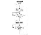
まず、ステップ31にて、シャッタ7Lとシャッタ7Rの双方を閉とする。このように、通常、両シャッタ7L,7Rは閉状態である。   First, at step 31, both the shutter 7L and the shutter 7R are closed. Thus, normally, both the shutters 7L and 7R are closed.

ステップ32では、島端タンク2Lの貯留球検出器81Lと島端タンク2Rの貯留球検出器81Rとのオン数に差があるか否かが判定される。つまり、島端タンク2Lの遊技球貯留量と島端タンク2Rの遊技球貯留量とに所定量以上の差があるかが判定される。判定の結果、貯留球検出器81Lと貯留球検出器81Rとのオン数に差があると判定されれば、ステップ33へと進む。また、判定の結果、オン数に差がない、つまり、オン数が同じであると判定されれば、ステップ31へと戻り両シャッタ7L,7Rは閉状態を維持する。   In step 32, it is determined whether or not there is a difference in the number of ONs between the stored ball detector 81L of the island end tank 2L and the stored ball detector 81R of the island end tank 2R. That is, it is determined whether there is a difference of a predetermined amount or more between the game ball storage amount of the island end tank 2L and the game ball storage amount of the island end tank 2R. As a result of the determination, if it is determined that there is a difference in the ON number between the storage ball detector 81L and the storage ball detector 81R, the process proceeds to step 33. As a result of the determination, if it is determined that there is no difference in the number of ONs, that is, it is determined that the number of ONs is the same, the process returns to step 31 and the shutters 7L and 7R maintain the closed state.

ステップ33では、島端タンク2Lの貯留球検出器81Lのオン数が島端タンク2Rの貯留球検出器81Rのオン数よりも多いか否かが判定される。判定の結果、島端タンク2Lの貯留球検出器81Lのオン数の方が多いと判定されれば、ステップ34へと進み、遊技球貯留量が多い島端タンク2Lのシャッタ7Lがシャッタモータ85Lの駆動によって開となり、島端タンク2Lに貯留された遊技球が遊技球回収装置1へと排出される。また、判定の結果、島端タンク2Rの貯留球検出器81Rのオン数の方が多いと判定されれば、ステップ35へと進み、遊技球貯留量が多い島端タンク2Rのシャッタ7Rがシャッタモータ85Rの駆動によって開となり、島端タンク2Rに貯留された遊技球が遊技球回収装置1へと排出される。   In step 33, it is determined whether or not the number of ONs of the stored ball detector 81L of the island end tank 2L is larger than the number of ONs of the stored ball detector 81R of the island end tank 2R. As a result of the determination, if it is determined that the number of ON of the stored ball detector 81L of the island end tank 2L is larger, the process proceeds to step 34, and the shutter 7L of the island end tank 2L having a large amount of game ball storage is operated by the shutter motor 85L. And the game balls stored in the island end tank 2L are discharged to the game ball collection device 1. If it is determined as a result of the determination that the number of stored ball detectors 81R in the island end tank 2R is larger, the process proceeds to step 35, and the shutter 7R of the island end tank 2R having a large amount of game ball storage is released. The game ball is opened by driving the motor 85R, and the game balls stored in the island end tank 2R are discharged to the game ball collection device 1.

このように、ステップ32及びステップ33では、島端タンク2L及び島端タンク2Rの一方の遊技球貯留量が他方の遊技球貯留量よりも所定量以上の差を持って多い場合には、その一方の島端タンク2に設けられたシャッタ7を開とする制御が行われる。   As described above, in step 32 and step 33, when one of the game ball storage amounts of the island end tank 2L and the island end tank 2R is larger than the other game ball storage amount by a predetermined amount or more, Control is performed to open the shutter 7 provided in one island end tank 2.

これにより、遊技球貯留量が多い島端タンク2に貯留された遊技球が遊技球回収装置1によって揚送装置3へと搬送されるため、左右の島端タンク2L,2Rの遊技球貯留量をバランスさせることができる。   As a result, the game balls stored in the island-end tank 2 with a large amount of game balls are transported to the lifting device 3 by the game-ball collecting device 1, so that the game-ball storage amounts in the left and right island-end tanks 2L and 2R Can be balanced.

ステップ34及びステップ35にてシャッタ7L,7Rが開となった後は、ステップ32へと戻り、判定の結果、島端タンク2Lの貯留球検出器81Lと島端タンク2Rの貯留球検出器81Rとのオン数が同じであると判定されれば、ステップ31へと進み、シャッタ7L,7Rは閉となる。このように、シャッタ7L,7Rは、島端タンク2L,2Rの遊技球貯留量がバランスするまでは開状態に維持される。   After the shutters 7L and 7R are opened in step 34 and step 35, the process returns to step 32, and as a result of the determination, the stored ball detector 81L of the island end tank 2L and the stored ball detector 81R of the island end tank 2R. If it is determined that the ON numbers are the same, the process proceeds to step 31, and the shutters 7L and 7R are closed. Thus, the shutters 7L and 7R are maintained in the open state until the game ball storage amounts of the island end tanks 2L and 2R are balanced.

以上の本実施の形態によれば、以下に示す作用効果を奏する。   According to the above embodiment, the following operational effects are obtained.

第一回収樋10から排出された遊技球を第二回収樋11へと搬送する搬送装置12を備えるため、一つの回収樋によって遊技球を搬送する場合と比較して、第一回収樋10及び第二回収樋11の高さを低くすることができる。したがって、高さ方向に大きなスペースを必要としない。   Since the transport device 12 for transporting the game balls discharged from the first recovery basket 10 to the second recovery basket 11 is provided, compared to the case where the game balls are transported by one recovery basket, the first recovery basket 10 and The height of the second recovery basket 11 can be reduced. Therefore, a large space in the height direction is not required.

また、遊技島100が長手方向に長い場合でも、遊技球回収装置1を直列に複数配列することによって、高さ制限のある遊技機下部においても、回収樋を遊技島100の端部まで配設させることが可能となる。   Even when the gaming island 100 is long in the longitudinal direction, a plurality of gaming ball collection devices 1 are arranged in series, so that a collection basket is arranged up to the end of the gaming island 100 even at the lower part of the gaming machine with a height restriction. It becomes possible to make it.

また、搬送装置12は、回転体20の外周縁に配設された磁性体の磁力によって、遊技球を回転体20の外周面に吸着させて搬送するものであり、破損するおそれがなく、安定して遊技球を搬送することができる。   Further, the transport device 12 transports the game ball by attracting it to the outer peripheral surface of the rotating body 20 by the magnetic force of the magnetic body disposed on the outer peripheral edge of the rotating body 20, and there is no risk of breakage and is stable. The game ball can be transported.

さらに、回転体20の外周縁に配設される磁性体として、硬磁性体23と共に、遊技球と磁気回路を構成する軟磁性体も備えるため、硬磁性体23は、回転体20周方向に所定間隔を空けて配設すれば足り、回転体20の外周全体に配設する必要がないため、コストを低減することができる。   Furthermore, since the magnetic body disposed on the outer peripheral edge of the rotating body 20 includes a hard magnetic body 23 and a soft magnetic body that forms a magnetic circuit with the game ball, the hard magnetic body 23 is arranged in the circumferential direction of the rotating body 20. It is sufficient to arrange them at a predetermined interval, and it is not necessary to arrange them on the entire outer periphery of the rotator 20, so that the cost can be reduced.

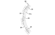
次に、本実施の形態の他の形態について説明する。   Next, another embodiment of the present embodiment will be described.

(1)図18に示すように、隣り合う硬磁性体23を、S極とN極が対向するようにして配設するのが望ましい。このように硬磁性体23を配設することによって、遊技球は隣り合う硬磁性体23に亘って吸着するため、回転体20の外周面により多くの遊技球を吸着させることができる。したがって、遊技球の搬送効率が向上する。   (1) As shown in FIG. 18, it is desirable to arrange the adjacent hard magnetic bodies 23 so that the S pole and the N pole face each other. By disposing the hard magnetic body 23 in this manner, the game balls are attracted over the adjacent hard magnetic bodies 23, so that more game balls can be attracted to the outer peripheral surface of the rotating body 20. Therefore, the transport efficiency of game balls is improved.

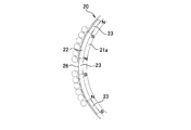
(2)図18では、回転体20の周方向にN極とS極が着磁された硬磁性体23を示したが、図19に示すように、回転体20の径方向にN極とS極が着磁された硬磁性体23を用いても上記(1)にて示した効果と同様の効果を奏する。   (2) Although FIG. 18 shows the hard magnetic body 23 in which the N pole and the S pole are magnetized in the circumferential direction of the rotating body 20, as shown in FIG. Even when the hard magnetic material 23 with the S pole magnetized is used, the same effect as the effect (1) is obtained.

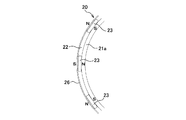
(3)上記実施の形態では、ゴム製の磁石ガイド22に硬磁性体23を保持させ、ベースドラム21の胴部21aを軟磁性体とした。これに代わり、図20に示すように、磁石ガイド22自体を環状の軟磁性体にて構成し、その磁石ガイド22をベースドラム21の外周に嵌挿させベースドラム21と一体に構成するようにしてもよい。   (3) In the above embodiment, the hard magnetic body 23 is held by the rubber magnet guide 22, and the body portion 21a of the base drum 21 is a soft magnetic body. Instead, as shown in FIG. 20, the magnet guide 22 itself is formed of an annular soft magnetic material, and the magnet guide 22 is inserted into the outer periphery of the base drum 21 so as to be integrated with the base drum 21. May be.

このように構成すれば、磁石ガイド22の外周面に、硬磁性体23と軟磁性体が周方向に交互に配設されるため、軟磁性体の磁力が遊技球に作用し易くなり、遊技球が回転体20の外周面に吸着し易くなる。   If comprised in this way, since the hard magnetic body 23 and the soft magnetic body will be alternately arrange | positioned by the circumferential direction on the outer peripheral surface of the magnet guide 22, it will become easy for the magnetic force of a soft magnetic body to act on a game ball, and a game The sphere is easily adsorbed to the outer peripheral surface of the rotating body 20.

(4)遊技島100に島端タンク2を設けずに、オーバーフローホース9bから排出される遊技球を遊技球回収装置1の第一回収樋10に直接導くようにしてもよい。   (4) Instead of providing the island end tank 2 on the game island 100, the game ball discharged from the overflow hose 9b may be directly guided to the first collection basket 10 of the game ball collection device 1.

(5)遊技島100に島端タンク2及びオーバーフロー樋9aを設けずに、オーバーフロー導入塔65又は連絡管66にオーバーフローホース9bを連通させ、上部タンク4をオーバーフローした遊技球を、第一回収樋10や第二回収樋11や排出樋87に排出するようにしてもよい。   (5) Without providing the island end tank 2 and the overflow rod 9a on the game island 100, the overflow hose 9b is communicated with the overflow introduction tower 65 or the communication pipe 66, and the game ball overflowing the upper tank 4 is collected in the first collection basket 10 or the second recovery rod 11 or the discharge rod 87 may be discharged.

(6)揚送装置3の周囲など、揚送装置3の近傍に中間タンクを設け、上部タンク4から供給樋6へと排出されず、上部タンク4をオーバーフローした遊技球を中間タンクに排出し、中間タンクの下流端側に設けたシャッタの開閉により、中間タンクに貯留された遊技球を、第一回収樋10や第二回収樋11や排出樋87へ排出するようにしても良い。   (6) An intermediate tank is provided in the vicinity of the lifting device 3 such as around the lifting device 3, and the game ball overflowing from the upper tank 4 is discharged to the intermediate tank without being discharged from the upper tank 4 to the supply basket 6. The game balls stored in the intermediate tank may be discharged to the first collection basket 10, the second collection basket 11 and the discharge basket 87 by opening and closing a shutter provided on the downstream end side of the intermediate tank.

(7)オーバーフロー導入塔65、連絡管66、及びオーバーフロー樋9aを設けない構成とし、上部タンク4の遊技球貯留量がリミットスイッチ71の位置まで達したら、揚送モータ58を停止するようにしてもよい。   (7) The overflow introduction tower 65, the connecting pipe 66, and the overflow rod 9a are not provided. When the amount of game balls stored in the upper tank 4 reaches the limit switch 71, the lifting motor 58 is stopped. Also good.

(8)上記実施の形態では、上部タンク4は、上部主タンク4Aと上部補助タンク4Bとから構成されるが、島間樋を設けないのであれば、上部主タンク4Aのみから構成するようにしてもよい。   (8) In the above embodiment, the upper tank 4 is composed of the upper main tank 4A and the upper auxiliary tank 4B. However, if no island ridge is provided, the upper tank 4 is composed only of the upper main tank 4A. Also good.

本発明は上記の実施の形態に限定されずに、その技術的な思想の範囲内において種々の変更がなしうることは明白である。   The present invention is not limited to the above-described embodiment, and it is obvious that various modifications can be made within the scope of the technical idea.

本発明の遊技球回収装置は、遊技機から排出された遊技球を回収して揚送装置に向けて搬送する装置として適用することができる。なお、遊技機としては、前記実施の形態に示されるようなパチンコ遊技機に限られるものではなく、例えば、その他のパチンコ遊技機、アレンジボール遊技機、雀球遊技機、スロットマシンなどの遊技球を使用する全ての遊技機に適用可能である。   The game ball collecting device of the present invention can be applied as a device that collects the game balls discharged from the gaming machine and conveys them to the lifting device. Note that the gaming machine is not limited to the pachinko gaming machine as shown in the above embodiment, and for example, other pachinko gaming machines, arrange ball gaming machines, sparrow ball gaming machines, slot machines and the like. It is applicable to all gaming machines that use

遊技島の内部構造を示す側面図である。It is a side view which shows the internal structure of amusement island. 遊技島の端部付近の内部構造を示す斜視図である。It is a perspective view which shows the internal structure of the edge part vicinity of amusement island. 遊技島の中央付近の内部構造を示す斜視図である。It is a perspective view which shows the internal structure of the center vicinity of amusement island. 揚送装置の斜視図である。It is a perspective view of a lifting apparatus. 上部タンクの内部の斜視図である。It is a perspective view of the inside of an upper tank. 上部タンクの内部の分解斜視図である。It is a disassembled perspective view of the inside of an upper tank. 本発明の実施の形態に係る遊技球回収装置の要部分解斜視図である。It is a principal part exploded perspective view of the game ball collection device concerning an embodiment of the invention. 本発明の実施の形態に係る遊技球回収装置の要部側面図である。It is a principal part side view of the game ball collection | recovery apparatus which concerns on embodiment of this invention. 本発明の実施の形態に係る遊技球回収装置における搬送装置の分解斜視図である。It is a disassembled perspective view of the conveyance apparatus in the game ball collection | recovery apparatus which concerns on embodiment of this invention. 搬送装置によって遊技球が搬送される過程を示す図である。It is a figure which shows the process in which a game ball is conveyed by the conveying apparatus. 図10の比較例を示す図である。It is a figure which shows the comparative example of FIG. 遊技球が回転体の外周面に吸着し搬送されている状態を示す図である。It is a figure which shows the state in which the game ball is adsorb | sucked and conveyed by the outer peripheral surface of a rotary body. 図12の比較例を示す図である。It is a figure which shows the comparative example of FIG. 遊技島制御装置のブロック図である。It is a block diagram of a game island control device. 揚送装置の起動停止の流れを示すフローチャートである。It is a flowchart which shows the flow of starting and stopping of a conveying apparatus. 遊技球回収装置の回転体の起動停止の流れを示すフローチャートである。It is a flowchart which shows the flow of starting and stopping of the rotary body of a game ball collection apparatus. 島端タンクのシャッタの開閉動作の流れを示すフローチャートである。It is a flowchart which shows the flow of the opening / closing operation | movement of the shutter of an island edge tank. 本発明の実施の形態に係る遊技球回収装置の他の形態を示す図である。It is a figure which shows the other form of the game ball collection | recovery apparatus which concerns on embodiment of this invention. 本発明の実施の形態に係る遊技球回収装置の他の形態を示す図である。It is a figure which shows the other form of the game ball collection | recovery apparatus which concerns on embodiment of this invention. 本発明の実施の形態に係る遊技球回収装置の他の形態を示す図である。It is a figure which shows the other form of the game ball collection | recovery apparatus which concerns on embodiment of this invention.

符号の説明Explanation of symbols

1 遊技球回収装置
2 島端タンク
3 揚送装置
4 上部タンク
7 シャッタ
8 球計数機
9a オーバーフロー樋
9b オーバーフローホース
10 第一回収樋
10b 下流端部
10c 転動面
11 第二回収樋
11a 上流端部
11c 転動面
12,12A,12B 搬送装置
20 回転体
21 ベースドラム
22 磁石ガイド
22a 保持部
23 硬磁性体
26 磁石カバー
41 供給ガイド
41a 転動面
42 排出ガイド
43 段差
44 ガイド部材
45 ガイド板
81 貯留球検出器
84 回収球検出器
100 遊技島
DESCRIPTION OF SYMBOLS 1 Game ball collection apparatus 2 Island end tank 3 Lifting apparatus 4 Upper tank 7 Shutter 8 Ball counter 9a Overflow gutter 9b Overflow hose 10 First collection gutter 10b Downstream end part 10c Rolling surface 11 Second collection gutter 11a Upstream end part 11c Rolling surfaces 12, 12A, 12B Conveying device 20 Rotating body 21 Base drum 22 Magnet guide 22a Holding portion 23 Hard magnetic body 26 Magnet cover 41 Supply guide 41a Rolling surface 42 Discharge guide 43 Step 44 Guide member 45 Guide plate 81 Storage Ball detector 84 Recovered ball detector 100

Claims (6)

複数の遊技機が配列された遊技島に設けられ、各遊技機から排出された遊技球を回収して、遊技島の上部に遊技球を揚送する揚送装置に向けて遊技球を搬送する遊技球回収装置において、
各遊技機から排出された遊技球を回収して下流端部に向けて転動可能な第一回収樋と、
上流端部が前記第一回収樋の下流端部よりも高い位置に設けられ、前記揚送装置側に向けて遊技球を転動可能な第二回収樋と、
前記第一回収樋から前記第二回収樋へと遊技球を搬送する搬送装置と、を備え、
前記搬送装置は、
駆動源からの駆動力を受けて回転軸を中心に回転する回転体と、
前記回転体の外周縁に配設され、該回転体の外周面に前記第一回収樋を転動してきた遊技球を吸着させるための硬磁性体と、を備え、
前記駆動源を駆動して前記回転体を回転させることで、当該回転体の外周面に吸着した遊技球を前記第二回収樋へ搬送し、
前記回転体は、前記硬磁性体と前記回転軸の間に前記硬磁性体と重合するように配設される軟磁性体を備えることを特徴とする遊技球回収装置。
Provided on a gaming island where a plurality of gaming machines are arranged, collects the gaming balls discharged from each gaming machine, and transports the gaming balls to a lifting device that lifts the gaming balls to the top of the gaming island In the game ball collection device,
A first recovery rod capable of collecting the game balls discharged from each gaming machine and rolling toward the downstream end;
A second recovery rod that has an upstream end provided at a position higher than the downstream end of the first recovery rod and is capable of rolling the game ball toward the lifting device;
A transporting device for transporting game balls from the first recovery basket to the second recovery basket;
The transfer device
A rotating body that receives a driving force from a driving source and rotates around a rotation axis;
A hard magnetic body disposed on the outer peripheral edge of the rotating body, for adsorbing the game ball that has rolled the first recovery rod on the outer peripheral surface of the rotating body,
By rotating the rotating body by driving the drive source, the game ball adsorbed on the outer peripheral surface of the rotating body is conveyed to the second collection basket ,
The game ball collecting apparatus according to claim 1, wherein the rotating body includes a soft magnetic body disposed so as to overlap with the hard magnetic body between the hard magnetic body and the rotating shaft .
前記硬磁性体は、前記回転体の周方向に所定の間隔を空けて配設されることを特徴とする請求項1に記載の遊技球回収装置。   2. The game ball collecting apparatus according to claim 1, wherein the hard magnetic body is disposed at a predetermined interval in a circumferential direction of the rotating body. 隣り合う前記硬磁性体は、S極とN極が対向して配設されることを特徴とする請求項2に記載の遊技球回収装置。 3. The game ball collecting apparatus according to claim 2, wherein the adjacent hard magnetic bodies are arranged so that the south pole and the north pole face each other. 前記回転体は、
前記回転軸を中心に回転するベースドラムと、
前記ベースドラムの外周に沿って配設され、前記硬磁性体を保持する磁石ガイドと、を備え、
前記ベースドラムの外周部は軟磁性体であり、
前記磁石ガイドは非磁性体であることを特徴とする請求項または請求項に記載の遊技球回収装置。
The rotating body is
A base drum that rotates about the rotation axis;
A magnet guide disposed along the outer periphery of the base drum and holding the hard magnetic body,
The outer periphery of the base drum is a soft magnetic material,
The magnet guide game ball collecting device of claim 2 or claim 3 characterized in that it is a non-magnetic material.
前記第二回収樋における遊技球の滞留状態を検出する回収球検出手段を備え、
前記回転体は、前記回収球検出手段の検出状況に応じて停止状態となることを特徴とする請求項1から請求項のいずれか一つに記載の遊技球回収装置。
A recovery ball detecting means for detecting a staying state of the game ball in the second recovery basket;
The game ball collecting device according to any one of claims 1 to 4 , wherein the rotating body is stopped according to a detection status of the collected ball detecting means.
請求項1から請求項のいずれか一つに記載の遊技球回収装置と、
遊技球を貯留可能であると共に、前記遊技球回収装置へと遊技球を排出可能な島端タンクと、を備え、
前記遊技球回収装置と前記島端タンクとが前記揚送装置の右側と左側にそれぞれ配設された遊技島において、
前記島端タンクは、
開閉可能に設けられ、開となることによって前記島端タンクに貯留された遊技球を前記遊技球回収装置の前記第一回収樋へと排出可能なシャッタと、
前記島端タンクにおける遊技球の貯留状態を検出する貯留球検出手段と、を備え、
一方の島端タンクの遊技球貯留量が他方の島端タンクの遊技球貯留量よりも所定量以上の差を持って多い場合には、前記一方の島端タンクに設けられた前記シャッタを開とすることを特徴とする遊技島。
The game ball collection device according to any one of claims 1 to 5 ,
An island end tank capable of storing the game balls and capable of discharging the game balls to the game ball collection device,
In the game island in which the game ball collecting device and the island end tank are respectively arranged on the right side and the left side of the lifting device,
The island edge tank
A shutter that is provided so as to be openable and closable, and that is capable of discharging the game ball stored in the island-end tank to the first collection basket of the game ball collection device;
A storage ball detection means for detecting the storage state of the game ball in the island edge tank,
When the amount of game balls stored in one island edge tank is larger than the amount of game balls stored in the other island edge tank by a predetermined amount or more, the shutter provided in the one island edge tank is opened. An amusement island characterized by
JP2008298325A 2008-11-21 2008-11-21 Game ball collection device and game island Expired - Fee Related JP5259357B2 (en)

Priority Applications (1)

Application Number Priority Date Filing Date Title
JP2008298325A JP5259357B2 (en) 2008-11-21 2008-11-21 Game ball collection device and game island

Applications Claiming Priority (1)

Application Number Priority Date Filing Date Title
JP2008298325A JP5259357B2 (en) 2008-11-21 2008-11-21 Game ball collection device and game island

Related Child Applications (1)

Application Number Title Priority Date Filing Date
JP2013047881A Division JP2013135924A (en) 2013-03-11 2013-03-11 Game ball collecting device

Publications (3)

Publication Number Publication Date
JP2010119774A JP2010119774A (en) 2010-06-03
JP2010119774A5 JP2010119774A5 (en) 2012-01-05
JP5259357B2 true JP5259357B2 (en) 2013-08-07

Family

ID=42321636

Family Applications (1)

Application Number Title Priority Date Filing Date
JP2008298325A Expired - Fee Related JP5259357B2 (en) 2008-11-21 2008-11-21 Game ball collection device and game island

Country Status (1)

Country Link
JP (1) JP5259357B2 (en)

Families Citing this family (1)

* Cited by examiner, † Cited by third party
Publication number Priority date Publication date Assignee Title
JP5259358B2 (en) * 2008-11-21 2013-08-07 株式会社エビスワーク Game ball collection device and game island

Family Cites Families (3)

* Cited by examiner, † Cited by third party
Publication number Priority date Publication date Assignee Title
JP4313883B2 (en) * 1999-03-29 2009-08-12 富士機械製造株式会社 Electrical component feeder
JP2006254956A (en) * 2005-03-15 2006-09-28 Sayama Precision Ind Co Ball lifting and sending apparatus
JP5259358B2 (en) * 2008-11-21 2013-08-07 株式会社エビスワーク Game ball collection device and game island

Also Published As

Publication number Publication date
JP2010119774A (en) 2010-06-03

Similar Documents

Publication Publication Date Title
JP5259358B2 (en) Game ball collection device and game island
JP5259280B2 (en) Game ball supply device
JP5259281B2 (en) Game ball supply device
JP5259357B2 (en) Game ball collection device and game island
JP5259355B2 (en) Game ball supply device and game island
JP5259356B2 (en) Game ball supply device and game island
JP2010119775A5 (en)
JP2013135924A (en) Game ball collecting device
JP2013135922A (en) Game ball feeder
JP5259282B2 (en) Game ball supply device
JP5371619B2 (en) Ball conveyor
JP5448725B2 (en) Game ball transport device
JP5280048B2 (en) Game ball supply device
JP5435369B2 (en) Game ball transport device
JP2011098186A (en) Game ball supply device
JP2013085690A (en) Game ball carrying device
JP2011139756A (en) Game ball supply device
JP5185675B2 (en) Game ball supply device
JP2010119774A5 (en)
JP5374066B2 (en) Game ball supply device
JP5280049B2 (en) Game ball supply device
JP5597100B2 (en) Game ball lifting device
JP2009279018A (en) Game ball feeder
JP5435367B2 (en) Game ball transport device
JP5435368B2 (en) Game ball transport device

Legal Events

Date Code Title Description
A521 Written amendment

Free format text: JAPANESE INTERMEDIATE CODE: A523

Effective date: 20111111

A621 Written request for application examination

Free format text: JAPANESE INTERMEDIATE CODE: A621

Effective date: 20111111

A977 Report on retrieval

Free format text: JAPANESE INTERMEDIATE CODE: A971007

Effective date: 20121228

A131 Notification of reasons for refusal

Free format text: JAPANESE INTERMEDIATE CODE: A131

Effective date: 20130108

A521 Written amendment

Free format text: JAPANESE INTERMEDIATE CODE: A523

Effective date: 20130311

TRDD Decision of grant or rejection written
A01 Written decision to grant a patent or to grant a registration (utility model)

Free format text: JAPANESE INTERMEDIATE CODE: A01

Effective date: 20130402

A61 First payment of annual fees (during grant procedure)

Free format text: JAPANESE INTERMEDIATE CODE: A61

Effective date: 20130424

FPAY Renewal fee payment (event date is renewal date of database)

Free format text: PAYMENT UNTIL: 20160502

Year of fee payment: 3

R150 Certificate of patent or registration of utility model

Free format text: JAPANESE INTERMEDIATE CODE: R150

LAPS Cancellation because of no payment of annual fees