JP5259342B2 - COMMUNICATION DEVICE AND RADIO RESOURCE ALLOCATION METHOD - Google Patents
COMMUNICATION DEVICE AND RADIO RESOURCE ALLOCATION METHOD Download PDFInfo
- Publication number
- JP5259342B2 JP5259342B2 JP2008278476A JP2008278476A JP5259342B2 JP 5259342 B2 JP5259342 B2 JP 5259342B2 JP 2008278476 A JP2008278476 A JP 2008278476A JP 2008278476 A JP2008278476 A JP 2008278476A JP 5259342 B2 JP5259342 B2 JP 5259342B2
- Authority
- JP
- Japan
- Prior art keywords
- communication
- determined
- communication partner
- signal
- predetermined
- Prior art date
- Legal status (The legal status is an assumption and is not a legal conclusion. Google has not performed a legal analysis and makes no representation as to the accuracy of the status listed.)
- Expired - Fee Related
Links
Images


Landscapes
- Mobile Radio Communication Systems (AREA)
Description
本発明は、OFDM(Orthogonal Frequency Division Multiplexing)方式で定義された複数のサブキャリアを用いて複数の通信相手装置と多元接続通信を行う通信装置及び当該通信装置での通品相手装置に対する無線リソースの割り当て方法に関する。 The present invention relates to a communication device that performs multiple access communication with a plurality of communication partner devices using a plurality of subcarriers defined by an OFDM (Orthogonal Frequency Division Multiplexing) method, and radio resources for a communication partner device in the communication device. It relates to the allocation method.
従来から無線通信に関して様々な技術が提案されている。例えば特許文献1には、WiMAX(Worldwide Interoperability for Microwave Access)と呼ばれる、OFDMA(Orthogonal Frequency Division Multiple Access)方式で通信を行う無線通信技術が開示されている。OFDMA方式では、OFDM方式で定義されたサブキャリア及びOFDMシンボルがユーザに適応的に割り当てられる。また特許文献2には、既知のトレーニング信号を用いて、無線信号が通過するチャネルの特性の推定を行うチャネルサウンディングシステムが開示されている。特許文献2には、MIMO(Multiple Input Multiple Output)システムにおいてチャネルサウンディングを行う技術が開示されている。
Conventionally, various techniques relating to wireless communication have been proposed. For example,
さて、上述の特許文献1にも記載されているように、WiMAXでは、基地局のアンテナとしてアダプティブアレイが使用されることがある。基地局では、通信端末から送信される、サウンディング信号と呼ばれる既知信号を用いてアダプティブアレイのウェイトを算出し、当該アダプティブアレイの指向性が当該通信端末に向くようにビームフォーミングされる。
As described in
一方で、通信端末は、基地局から指定されたサブキャリアを用いてサウンディング信号を送信する。WiMAXでは、通信端末がサウンディング信号を送信する際に使用するサブキャリアとして、固定数の複数のサブキャリア(例えば、OFDM方式で定義されているすべてのサブキャリア)が定められており、その固定数の複数のサブキャリアを通信対象となる複数の通信端末に対して重複しないように割り振っている。通信端末では、サウンディング信号を送信する際に使用するサブキャリアの数が多くなると、サブキャリアあたりの送信電力が小さくなることから、基地局がサウンディング信号の送信のために通信端末に割り当てるサブキャリアの数によっては、当該通信端末から送信されるサウンディング信号を基地局が受信しにくくなる。 On the other hand, the communication terminal transmits a sounding signal using a subcarrier designated by the base station. In WiMAX, a fixed number of subcarriers (for example, all subcarriers defined in the OFDM scheme) are defined as subcarriers used when a communication terminal transmits a sounding signal. Are assigned to a plurality of communication terminals to be communicated so as not to overlap. In the communication terminal, if the number of subcarriers used when transmitting the sounding signal increases, the transmission power per subcarrier decreases, so the base station assigns the subcarrier allocated to the communication terminal for transmitting the sounding signal. Depending on the number, it becomes difficult for the base station to receive the sounding signal transmitted from the communication terminal.
そこで、本発明は上述の点に鑑みて成されたものであり、OFDM方式で定義された複数のサブチャネルを用いて複数の通信相手装置と多元接続通信を行う通信装置において、通信相手装置から送信される所定の信号を受信しやすくすることが可能な技術を提供することを目的とする。 Therefore, the present invention has been made in view of the above points. In a communication device that performs multiple access communication with a plurality of communication partner devices using a plurality of subchannels defined in the OFDM scheme, the communication partner device It is an object of the present invention to provide a technique capable of easily receiving a predetermined signal to be transmitted.
上記課題を解決するため、本発明に係る通信装置は、OFDM(Orthogonal Frequency Division Multiplexing)方式で定義された複数のサブキャリアを用いて複数の通信相手装置と多元接続通信を行う通信装置であって、通信相手装置から送信される信号を受信する受信部と、前記受信部で受信された信号に基づいて、当該信号を送信した通信相手装置との通信品質が所定の基準を満たすか否かを判定する判定部と、通信対象となる複数の通信相手装置を決定し、当該複数の通信相手装置のそれぞれに対して、所定の信号の送信用の無線リソースを割り当てる無線リソース割り当て部と、前記無線リソース割り当て部での割り当て結果を示す割り当て情報を、前記無線リソース割り当て部が通信対象として決定した複数の通信相手装置に送信する送信部とを備え、前記所定の信号の送信用のサブキャリアとして、固定数の複数のサブキャリアが定められており、前記無線リソース割り当て部は、QoSに基づき決定される通信優先順位が所定のレベル以上の通信相手装置と、自通信装置に対する上り方向の通信が留保されている時間が所定時間よりも長い通信相手装置とを通信対象として決定しても、当該通信対象として決定した通信相手装置の数が、自通信装置に対する上り方向において通信可能な通信相手装置の最大数より小さい場合には、前記判定部において通信品質が所定の基準を満たさないと判定された通信相手装置を通信対象として決定し、通信対象として決定した複数の通信相手装置のそれぞれに対して前記所定の信号の送信用の無線リソースを割り当てる際には、当該複数の通信相手装置に対して前記固定数の複数のサブキャリアのすべてを重複しないように均等に割り当てる。 In order to solve the above problems, a communication apparatus according to the present invention is a communication apparatus that performs multiple access communication with a plurality of communication partner apparatuses using a plurality of subcarriers defined by an OFDM (Orthogonal Frequency Division Multiplexing) scheme. Whether or not the communication quality between the receiving unit that receives the signal transmitted from the communication partner device and the communication partner device that transmitted the signal satisfies a predetermined criterion based on the signal received by the receiving unit. A determination unit for determining, a plurality of communication partner devices to be communicated, a radio resource assignment unit for allocating a radio resource for transmitting a predetermined signal to each of the plurality of communication partner devices, and the radio A transmission unit for transmitting allocation information indicating an allocation result in the resource allocation unit to a plurality of communication partner devices determined as communication targets by the radio resource allocation unit; Includes, as a sub-carrier for transmission of the predetermined signal, a plurality of sub-carriers of a fixed number is defined, the radio resource assignment unit, communication communication priority is determined based on the QoS is equal to or larger than a predetermined level Even if the partner device and the communication partner device for which the communication in the upstream direction with respect to the self-communication device is reserved are longer than the predetermined time as the communication target, the number of the communication partner device determined as the communication target is If the communication partner device is smaller than the maximum number of communication partner devices communicable in the uplink direction with respect to the own communication device, the communication partner device determined that the communication quality does not satisfy a predetermined standard in the determination unit is determined as a communication target , and communication is performed. when for each of a plurality of communication partner device determined as the target allocates radio resources for transmission of the predetermined signal, the plurality of through Equally allocated so as not to overlap all of the plurality of sub-carriers of the fixed number to the peer device.
また、本発明に係る通信装置は、OFDM(Orthogonal Frequency Division Multiplexing)方式で定義された複数のサブキャリアを用いて複数の通信相手装置と多元接続通信を行う通信装置であって、通信相手装置から送信される、当該通信相手装置の送信能力を示す情報を含む信号を受信する受信部と、前記受信部で受信された信号に基づいて、当該信号を送信した通信相手装置の送信能力が所定の基準を満たすか否かを判定する判定部と、通信対象となる複数の通信相手装置を決定し、当該複数の通信相手装置のそれぞれに対して、所定の信号の送信用の無線リソースを割り当てる無線リソース割り当て部と、前記無線リソース割り当て部での割り当て結果を示す割り当て情報を、前記無線リソース割り当て部が通信対象として決定した複数の通信相手装置に送信する送信部とを備え、前記所定の信号の送信用のサブキャリアとして、固定数の複数のサブキャリアが定められており、前記無線リソース割り当て部は、QoSに基づき決定される通信優先順位が所定のレベル以上の通信相手装置と、自通信装置に対する上り方向の通信が留保されている時間が所定時間よりも長い通信相手装置とを通信対象として決定しても、当該通信対象として決定した通信相手装置の数が、自通信装置に対する上り方向において通信可能な通信相手装置の最大数より小さい場合には、前記判定部において送信能力が所定の基準を満たさないと判定された通信相手装置を通信対象として決定し、通信対象として決定した複数の通信相手装置のそれぞれに対して前記所定の信号の送信用の無線リソースを割り当てる際には、当該複数の通信相手装置に対して前記固定数の複数のサブキャリアのすべてを重複しないように均等に割り当てる。 Further, a communication device according to the present invention is a communication device that performs multiple access communication with a plurality of communication partner devices using a plurality of subcarriers defined by an OFDM (Orthogonal Frequency Division Multiplexing) method. A receiving unit that receives a signal including information indicating the transmission capability of the communication counterpart device, and a transmission capability of the communication counterpart device that has transmitted the signal based on the signal received by the reception unit is predetermined. A determination unit that determines whether or not a criterion is satisfied, and a plurality of communication partner devices that are communication targets, and a wireless device that assigns a radio resource for transmitting a predetermined signal to each of the plurality of communication partner devices A resource allocation unit, and a plurality of communication phases determined by the radio resource allocation unit as communication targets, including allocation information indicating allocation results in the radio resource allocation unit. And a transmission unit for transmitting apparatus, as a sub-carrier for transmission of the predetermined signal, a plurality of sub-carriers of a fixed number has been established, the radio resource assignment unit, a communication priority is determined based on the QoS Even if a communication partner device whose rank is a predetermined level or more and a communication partner device in which uplink communication with the communication device is reserved for longer than a predetermined time is determined as a communication target, it is determined as the communication target. the number of the communication partner device, is smaller than the maximum number of available communication partner device in the uplink direction for the own communication device, the transmit capability does not satisfy a predetermined criterion in the determination unit determined to be the communication partner device It determines as the communication target, dividing the radio resources for transmission of the predetermined signal for each of a plurality of communication partner device determined as the communication target those When that is equally allocated so as not to overlap all of the plurality of sub-carriers of the fixed number with respect to the plurality of communication partner device.
また、本発明に係る通信装置の一態様では、前記受信部及び前記送信部はアンテナとしてアダプティブアレイを共用し、前記所定の信号は前記アダプティブアレイのウェイトの算出に使用される既知信号である。 In one aspect of the communication apparatus according to the present invention, the receiving unit and the transmitting unit share an adaptive array as an antenna, and the predetermined signal is a known signal used for calculating the weight of the adaptive array.
また、本発明に係る通信装置の一態様では、前記通信装置はWiMAX(Worldwide Interoperability for Microwave Access)での基地局であって、前記所定の信号はWiMAXで使用されるサウンディング信号である。 In one aspect of the communication apparatus according to the present invention, the communication apparatus is a WiMAX (Worldwide Interoperability for Microwave Access) base station, and the predetermined signal is a sounding signal used in WiMAX.
また、本発明に係る無線リソース割り当て方法は、OFDM(Orthogonal Frequency Division Multiplexing)方式で定義された複数のサブキャリアを用いて複数の通信相手装置と多元接続通信を行う通信装置での通信相手装置に対する無線リソースの割り当て方法であって、(a)通信相手装置から送信される信号を受信する工程と、(b)前記工程(a)で受信された信号に基づいて、当該信号を送信した通信相手装置との通信品質が所定の基準を満たすか否かを判定する工程と、(c)通信対象となる複数の通信相手装置を決定し、当該複数の通信相手装置のそれぞれに対して、所定の信号の送信用の無線リソースを割り当てる工程と、(d)前記工程(c)での割り当て結果を示す割り当て情報を、前記工程(c)において通信対象として決定された複数の通信相手装置に送信する工程とを備え、前記所定の信号の送信用のサブキャリアとして、固定数の複数のサブキャリアが定められており、前記工程(c)では、QoSに基づき決定される通信優先順位が所定のレベル以上の通信相手装置と、自通信装置に対する上り方向の通信が留保されている時間が所定時間よりも長い通信相手装置とが通信対象として決定されても、当該通信対象として決定された通信相手装置の数が、自通信装置に対する上り方向において通信可能な通信相手装置の最大数より小さい場合には、前記工程(b)において通信品質が所定の基準を満たさないと判定された通信相手装置が通信対象として決定され、通信対象として決定された複数の通信相手装置のそれぞれに対して前記所定の信号の送信用の無線リソースが割り当てられる際には、当該複数の通信相手装置に対して前記固定数の複数のサブキャリアのすべてが重複しないように均等に割り当てられる。 In addition, a radio resource allocation method according to the present invention is provided for a communication partner device in a communication device that performs multiple access communication with a plurality of communication partner devices using a plurality of subcarriers defined by an OFDM (Orthogonal Frequency Division Multiplexing) scheme. A method of assigning radio resources, comprising: (a) receiving a signal transmitted from a communication partner device; and (b) a communication partner transmitting the signal based on the signal received in step (a). A step of determining whether or not the communication quality with the device satisfies a predetermined standard; and (c) determining a plurality of communication partner devices to be communicated with each other, A step of allocating radio resources for signal transmission; and (d) allocation information indicating an allocation result in the step (c) is determined as a communication target in the step (c). And a step of transmitting a plurality of communication partner device, a sub-carrier for transmission of the predetermined signal, a plurality of sub-carriers of a fixed number is defined, In the step (c), it is determined based on the QoS Even if a communication partner device whose communication priority is higher than a predetermined level and a communication partner device in which uplink communication with the own communication device is reserved for a predetermined time is determined as communication targets, When the number of communication partner devices determined as targets is smaller than the maximum number of communication partner devices communicable in the uplink direction with respect to the own communication device , the communication quality does not satisfy a predetermined standard in the step (b). the determined communication partner device is determined as the communication target wireless Li for transmission of the predetermined signal for each of a plurality of communication partner devices that are determined as the communication target When the over scan is assigned, all of the plurality of sub-carriers of the fixed number is allocated evenly so as not to overlap with respect to the plurality of communication partner device.
また、本発明に係る無線リソース割り当て方法は、OFDM(Orthogonal Frequency Division Multiplexing)方式で定義された複数のサブキャリアを用いて複数の通信相手装置と多元接続通信を行う通信装置での通信相手装置に対する無線リソースの割り当て方法であって、(a)通信相手装置から送信される、当該通信相手装置の送信能力を示す情報を含む信号を受信する工程と、(b)前記工程(a)で受信された信号に基づいて、当該信号を送信した通信相手装置の送信能力が所定の基準を満たすか否かを判定する工程と、(c)通信対象となる複数の通信相手装置を決定し、当該複数の通信相手装置のそれぞれに対して、所定の信号の送信用の無線リソースを割り当てる工程と、(d)前記工程(c)での割り当て結果を示す割り当て情報を、前記工程(c)において通信対象として決定された複数の通信相手装置に送信する工程とを備え、前記工程(c)では、QoSに基づき決定される通信優先順位が所定のレベル以上の通信相手装置と、自通信装置に対する上り方向の通信が留保されている時間が所定時間よりも長い通信相手装置とが通信対象として決定されても、当該通信対象として決定された通信相手装置の数が、自通信装置に対する上り方向において通信可能な通信相手装置の最大数より小さい場合には、前記工程(b)において送信能力が所定の基準を満たさないと判定された通信相手装置が通信対象として決定され、通信対象として決定された複数の通信相手装置のそれぞれに対して前記所定の信号の送信用の無線リソースが割り当てられる際には、当該複数の通信相手装置に対して前記固定数の複数のサブキャリアのすべてが重複しないように均等に割り当てられる。 In addition, a radio resource allocation method according to the present invention is provided for a communication partner device in a communication device that performs multiple access communication with a plurality of communication partner devices using a plurality of subcarriers defined by an OFDM (Orthogonal Frequency Division Multiplexing) scheme. A method of allocating radio resources, comprising: (a) receiving a signal transmitted from a communication partner device that includes information indicating the transmission capability of the communication partner device; and (b) received in step (a). A step of determining whether or not the transmission capability of the communication partner apparatus that transmitted the signal satisfies a predetermined standard based on the received signal; and (c) determining a plurality of communication partner apparatuses to be communicated, Assigning radio resources for transmission of a predetermined signal to each of the communication counterpart devices, and (d) assignment information indicating assignment results in the step (c) And a step of transmitting in step (c) to a plurality of communication partner devices that are determined as the communication target, wherein the step (c), the communication priority and more than a predetermined level of the communication partner device that is determined based on the QoS Even if a communication partner device for which the uplink communication with the own communication device is reserved is longer than a predetermined time is determined as a communication target, the number of communication partner devices determined as the communication target is When the communication partner device is smaller than the maximum number of communication partner devices that can communicate in the uplink direction with respect to the device, the communication partner device determined that the transmission capability does not satisfy the predetermined standard in the step (b) is determined as a communication target , and communication is performed. when radio resources for transmission of the predetermined signal to each is allocated a plurality of communication partner devices that are determined as the subject, the plurality of communication phase All of the plurality of sub-carriers of the fixed number is allocated evenly so as not to overlap with respect to the device.
本発明によれば、通信相手装置からの所定の信号を受信しやすくなる。 According to the present invention, it becomes easy to receive a predetermined signal from a communication partner apparatus.
実施の形態1.
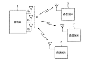
図1は本発明の実施の形態1に係る無線通信システムの構成を示す図である。また図2は、本実施の形態1に係る無線通信システムが備える基地局1の構成を示す図である。本実施の形態1に係る無線通信システムは、例えば、IEEE802.16eに規定されているモバイルWiMAXに準拠したシステムであって、基地局1はOFDMA方式で複数の通信端末2と双方向の無線通信を行う。OFDMA方式で通信を行う基地局1は、サブチャネルとOFDMシンボルとで特定される無線リソースを複数の通信端末2のそれぞれに個別に割り当てることによって、当該複数の通信端末2と同時に通信することが可能となっている。
FIG. 1 is a diagram showing a configuration of a radio communication system according to
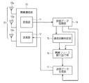
図2に示されるように、基地局1は、受信部11及び送信部12を有する無線通信部10と、受信データ処理部14と、通信品質判定部15と、無線リソース割り当て部16と、送信データ生成部17とを備えている。受信部11及び送信部12は、アンテナとして、複数のアンテナ素子13aから成るアダプティブアレイ13を共有している。つまり、アダプティブアレイ13は、通信端末2に無線信号を送信する送信アンテナ及び通信端末2からの無線信号を受信する受信アンテナとして機能する。
As shown in FIG. 2, the
受信部11は、アダプティブアレイ13の複数のアンテナ素子13aで受信された信号のそれぞれに対して増幅処理やダウンコンバートを行って、複数のアンテナ素子13aで受信された信号をそれぞれベースバンド信号に変換して出力する。
The
受信データ処理部14は、受信部11から出力される複数のベースバンド信号のそれぞれに対してウェイトを設定して(重み付けを行って)、各ベースバンド信号の位相及び振幅を制御する。そして受信データ処理部14は、ウェイト設定後の複数のベースバンド信号を合成する。これにより、アダプティブアレイ13のビームを希望波に向けることができ、妨害波を除去することができる。受信データ処理部14は、ウェイト設定後のベースバンド信号を合成して得られた信号(以後、「合成ベースバンド信号」と呼ぶ)に対して復調処理等を行って、通信対象の各通信端末2からの各種データを再生する。
The reception
また、受信データ処理部14は、アダプティブアレイ13のウェイトを、通信端末2から送信されてくるサウンディング信号を用いて決定する。ここで、サウンディング信号は既知の信号であるため、基地局1の受信データ処理部14は、通信端末2から送信されてくるサウンディング信号がどのような信号であるかを認識している。受信データ処理部14は、合成ベースバンド信号に対して復調処理等を行って、通信端末2からのサウンディング信号が適切に再生できるようなウェイトを算出し、それを、受信部11から出力される複数のベースバンド信号のそれぞれに対して設定する。
The reception
通信品質判定部15は、受信データ処理部14で生成された合成ベースバンド信号に基づいて、基地局1と通信端末2との間の通信品質が所定の基準を満足しているかどうかを判定する。例えば、通信品質判定部15は、合成ベースバンド信号に基づいて、通信対象の通信端末2についてのRSSI(Received Signal Strength Indicator)を算出し、算出したRSSIが所定のしきい値未満かどうかを判定する。これにより、通信品質判定部15は、基地局1との通信品質の悪い通信端末2を特定することができる。なお、基地局1と通信端末2との間の通信品質は、SNR(Signal to Noise Ratio)を用いて判定しても良い。
The communication
無線リソース割り当て部16は、下り方向の通信において通信対象となる通信端末2を決定するとともに、通信対象と決定した各通信端末2に割り当てる無線リソースを決定する。つまり、無線リソース割り当て部16は、下り方向の通信対象の通信端末2にデータを送信する際に使用する無線リソースを通信端末2ごとに決定する。
The radio
また無線リソース割り当て部16は、上り方向の通信において通信対象となる通信端末2を決定するとともに、通信対象と決定した各通信端末2に割り当てる無線リソースを決定する。つまり、無線リソース割り当て部16は、上り方向の通信対象の通信端末2が基地局1にデータを送信する際に使用する無線リソースを通信端末2ごとに決定する。複数の通信端末2に無線リソースが割り当てられる際には、各OFDMシンボルにおいて、周波数軸上に配置された複数のサブキャリアが重複しないように複数の通信端末2に割り当てられる。
The radio
送信データ生成部17は、無線リソース割り当て部16での無線リソースの割り当て結果を考慮してシリアル送信データを生成する。そして、送信データ生成部17は、シリアル送信データをパラレル送信データに変換して、当該パラレル送信データで、送信に使用する複数のサブキャリアを変調する。送信データ生成部17は、変調後の複数のサブキャリアを合成してベースバンド信号を生成する。このベースバンド信号は、アンテナ素子13aの数だけ準備される。送信データ生成部17は、受信データ処理部14で使用されたアダプティブアレイの受信用のウェイトに基づいて送信用のウェイトを決定し、当該送信用のウェイトを、生成した複数のベースバンド信号に設定する。そして、送信データ生成部17は、ウェイト設定後の複数のベースバンド信号を送信部12に出力する。
The transmission
送信部12は、入力された複数のベースバンド信号を、アップコンバート及び増幅処理を行った後、複数のアンテナ素子13aにそれぞれ入力する。これにより、アダプティブアレイ13からは、通信対象の通信端末2に向かって無線信号が送信される。
The
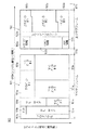
次に、モバイルWiMAXでのフレーム100の構成について説明する。図3はフレーム100の構成例を示す図である。モバイルWiMAXでは、基地局1と通信端末2との間の複信方式には、TDD(Time Division Duplexing、時分割複信)方式が採用されている。図3に示されるように、一つのフレーム100は、基地局1から通信端末2へ信号を送信するための下りサブフレーム101と、通信端末2から基地局1に信号を送信するための上りサブフレーム102とで構成されている。そして、フレーム100内には、基地局1が送信から受信に切り替える際のガード時間であるTGG(Transmit Transition Gap)と、基地局1が受信から送信に切り替える際のガード時間であるRTG(Receive Transition Gap)が設けられている。
Next, the configuration of the
図3に示されるように、下りサブフレーム101と上りサブフレーム102のそれぞれは、OFDMシンボルの番号で与えられる時間軸と、サブチャネルの番号で与えられる周波数軸とから成る2次元で表現される。ここで、OFDMA方式では、複数のサブキャリアが複数のサブチャネルにグループ分けされ、通信端末2へのサブキャリアの割り当ては、サブチャネル単位で行われる。OFDMA方式では、各通信端末2に対する無線リソースの割り当てが、周波数軸と時間軸とで表現される2次元で行われる。
As shown in FIG. 3, each of the
下りサブフレーム101には、例えば、プリアンブル領域101a、FCH(Frame Control Header)領域101b、DL−MAP(Downlink Map)メッセージ101c、UL−MAP(Uplink Map)メッセージ101d及び複数の下りバースト領域101eが配置される。下りサブフレーム101における、プリアンブル領域101a等の各領域の範囲は、サブチャネル数とOFDMシンボル数とで決定される。このような下りサブフレーム101は、基地局1の送信データ生成部17で生成される。
In the
一方で、上りサブフレーム102には、例えば、レンジング領域102a、CQICH領域102b、ACK領域102c、サウンディングゾーン102d及び複数の上りバースト領域102eが配置される。下りサブフレーム101と同様に、上りサブフレーム102における、レンジング領域102a等の各領域の範囲は、サブチャネル数とOFDMシンボル数とで決定される。
On the other hand, in the
プリアンブル領域101aには、通信端末2が基地局1との同期をとるために必要な信号が含められる。FCH領域101bには、DL−MAPメッセージ101cの長さと、そこで使用されている誤り訂正符号の方式及び繰り返し符号の繰り返し数を示すDLFP(Downlink Frame Prefix)などが含められる。通信端末2はDLFPの内容に従ってDL−MAPメッセージ101cを復調する。
In the
複数の下りバースト領域101eのそれぞれには、互いに異なった通信端末2がDL−MAPメッセージ101cによって割り当てられており、各下りバースト領域101eには、対応する通信端末2へのデータが含められる。図3の下りサブフレーム101では、5つの下りバースト領域101eに対して、♯1〜♯5までの5つの通信端末2がそれぞれ割り当てられている。したがって、図3の下りサブフレーム101においては5つの通信端末2に対するデータが含められる。
Each of the plurality of
DL−MAPメッセージ101cは、それが属する下りサブフレーム101において通信を行う各通信端末2に対する無線リソースの割り当てを示している。DL−MAPメッセージ101cには、下りサブフレーム101において各下りバースト領域101eがどの領域に割り当てられているのか、各下りバースト領域101eに対してどの通信端末2が割り当てられているのかなどの情報が含まれている。したがって、DL−MAPメッセージ101cによって、それが属する下りサブフレーム101で通信を行う通信端末2と、当該通信端末2と通信を行う際に使用されるサブチャネルと、当該通信端末2と通信を行う時間帯とが特定される。各通信端末2は、DL−MAPメッセージ101cの内容を解析することによって、自装置宛のデータが基地局1からどの時間帯(OFDMシンボル)でどのサブチャネルを使用して送信されるかを知ることができる。その結果、各通信端末2では、基地局1からの自装置宛のデータを適切に受信することができる。
The DL-
UL−MAPメッセージ101dは、それが属する下りサブフレーム101に続く上りサブフレーム102において通信対象となる各通信端末2に対する無線リソースの割り当てを示している。UL−MAPメッセージ101dには、上りサブフレーム102において各上りバースト領域102eがどの領域に割り当てられているのか、上りサブフレーム102中の各上りバースト領域102eに対してどの通信端末2が割り当てられているのかなどの情報が含まれている。したがって、UL−MAPメッセージ101dによって、それが属する下りサブフレーム101に続く上りサブフレーム102において通信を行う通信端末2と、当該通信端末2と通信を行う際に使用されるサブチャネルと、当該通信端末2と通信を行う時間帯とが特定される。各通信端末2は、UL−MAPメッセージ101dの内容を解析することによって、基地局1宛のデータをどの時間帯でどのサブチャネルを使用して送信すべきかを知ることができる。
The UL-
上りサブフレーム102での複数の上りバースト領域102eのそれぞれには、互いに異なった通信端末2がUL−MAPメッセージ101dによって割り当てられており、各上りバースト領域102eには、対応する通信端末2が送信するデータが含められる。図3の上りサブフレーム102では、3つの上りバースト領域102eに対して、♯1〜♯3までの3つの通信端末2がそれぞれ割り当てられている。したがって、図3の上りサブフレーム102においては3つの通信端末2からのデータが含められる。
A
レンジング領域102aには、帯域要求やレンジングを行うための信号が含められる。CQICH領域102bにはチャネル品質情報が含められる。ACK領域102cには、基地局1からのHARQ(Hybrid Automatic Repeat Request)に対するACK(Acknowledgement)あるいはNACK(Negative Acknowledgement)が含められる。
The ranging
サウンディングゾーン102dには、基地局1の受信データ処理部14がアダプティブアレイ13のウェイトを算出する際に使用する既知のサウンディング信号が含められる。サウンディングゾーン102dには、例えば、すべてのサブチャネル、つまりすべてのサブキャリアが割り当てられている。サウンディングゾーン102dに割り当てられている複数のサブチャネルは、当該サウンディングゾーン102dが属する上りサブフレーム102において基地局1と通信を行う複数の通信端末2に対して重複しないように割り振られている。上りサブフレーム102において基地局1と通信を行う各通信端末2は、サウンディング信号を、割り当てられているサブチャネルを使用して基地局1に送信する。なお、上りサブフレーム102において基地局1と通信を行う通信端末2が一つの場合には、当該一つの通信端末2にすべてのサブチャネルが割り当てられ、当該一つの通信端末2は、すべてのサブチャネルを使用してサウンディング信号を送信する。
The sounding
図4はサウンディングゾーン102dにおける各サブチャネルの通信端末2への割り当て例を示す図である。図4中の♯1〜♯3は、図3の3つの上りバースト領域102eにそれぞれ割り当てられている3つの通信端末2を示している。図4に示される例では、サウンディングゾーン102dに割り当てられている複数のサブチャネルのそれぞれには、♯1〜♯3の3つの通信端末2のいずれか一つが割り当てられている。より具体的には、番号順に並べられた複数のサブチャネルに対して、♯1〜♯3の通信端末2が、最初のサブチャネルから最後のサブチャネルに向かって順番に繰り返して割り当てられている。
FIG. 4 is a diagram showing an example of assignment of each subchannel to the
このように、モバイルWiMAXにおいては、通信端末2がサウンディング信号を送信する際に使用するサブキャリアとして定められている固定数のサブキャリア(本実施の形態1では、OFDMAで規定されているすべてのサブキャリア)が、上りサブフレーム102での通信対象の複数の通信端末2に重複しないように割り当てられている。したがって、上りサブフレーム102において基地局1と通信を行う通信端末2の数が少なくなると、上りサブフレーム102において基地局1と通信を行う各通信端末2がサウンディング信号を送信する際に使用するサブキャリアの数が多くなる。このような通信端末2に対するサブキャリアの割り当ては、下りサブフレーム101のUL−MAPメッセージ101dで行われている。UL−MAPメッセージ101dでは、それが属する下りサブフレーム101に続く上りサブフレーム102において基地局1と通信する各通信端末2がサウンディング信号を送信する際にどのサブチャネルを使用するかが記述されている。UL−MAPメッセージ101dを含む下りサブフレーム101の後に続く上りサブフレーム102において基地局1と通信を行う各通信端末2は、当該UL−MAPメッセージ101dにおいて自装置用として指定されているサブチャネル(複数のサブキャリア)を使用してサウンディング信号を基地局1に送信する。具体的には、通信端末2は、指定された複数のサブキャリアをサウンディング信号で変調し、変調後の複数のサブキャリアを重畳して得られる信号を基地局1に送信する。
Thus, in mobile WiMAX, a fixed number of subcarriers defined as subcarriers used when
本実施の形態1に係る無線通信システムでは、上りサブフレーム102において、基地局1との通信品質の悪い通信端末2ができるだけまとまって基地局1と通信するようになっている。これにより、通信品質の悪い通信端末2がサウンディング信号を送信する際に使用するサブキャリアの数が少なくなり、通信品質の悪い通信端末2は、サウンディング信号を送信する際のサブキャリアあたりの送信電力を大きくすることができる。その結果、基地局1は、通信端末2からサブキャリア信号を受信しやすくなる。以下に、このことについて詳細に説明する。
In the radio communication system according to the first embodiment, in the
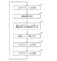
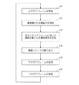
図5は、上りサブフレーム102で通信を行う通信端末2が決定され、その結果を反映したUL−MAPメッセージ101dを含む下りサブフレーム101が送信されるまでの基地局1の動作を示すフローチャートである。
FIG. 5 is a flowchart illustrating the operation of the
図5に示されるように、基地局1では、まずステップs1において、アダプティブアレイ13の複数のアンテナ素子13aが、上りサブフレーム102を含む無線信号を受信すると、受信部11は、複数のアンテナ素子13aで受信された信号のそれぞれをベースバンド信号に変換して出力する。受信データ処理部14は、受信部11から出力される複数のベースバンド信号のそれぞれに対してウェイトを設定し、ウェイト設定後のベースバンド信号を合成して合成ベースバンド信号を生成する。そして、受信データ処理部14は、合成ベースバンド信号に対して復調処理等を行って、それに含まれる上りサブフレーム102の各種情報を取得する。
As shown in FIG. 5, in the
次にステップs2において、通信品質判定部15は、受信データ処理部14で生成された合成ベースバンド信号に基づいて、ステップs1で受信した上りサブフレーム102での通信対象の各通信端末2について、基地局1との通信品質が所定の基準を満足しているかどうかを判定する。具体的には、通信品質判定部15は、合成ベースバンド信号に基づいて、当該合成ベースバンド信号に含まれるデータを送信した各通信端末2についてのRSSIを算出し、通信端末2ごとに、算出したRSSIが所定のしきい値未満かどうかを判定する。
Next, in step s2, the communication
なお、ステップs2は、基地局1が上りサブフレーム102を受信するたびに実行されるため、通信品質判定部15では、基地局1が通信可能な通信端末2のすべてについての通信品質が判定される。
Since step s2 is executed every time the
次にステップs3において、無線リソース割り当て部16は、次の上りサブフレーム102において通信対象となる通信端末2を決定する。ここで、次の上りサブフレーム102において通信可能な通信端末2の最大数を“N”とする。
Next, in step s3, the radio
ステップs3では、まず、無線リソース割り当て部16は、現時点において、上り方向の通信を行うべき通信端末2のすべてについての通信優先順位を確認する。ここで、通信優先順位とは、通信端末2のQoS(Quality of Service)に基づいて決定された通信の優先順位であって、通信優先順位が高い通信端末2ほど優先的に基地局1は通信を行うべきであることを意味する。この通信優先順位は、受信データ処理部14が、通信端末2からの受信データに基づいて決定して無線リソース割り当て部16に通知する。無線リソース割り当て部16は、通信優先順位が所定のレベル以上の通信端末2を、優先順位の高いもの順に次の上りサブフレーム102での通信対象としていく。ここで、通信対象と決定された通信端末2の数が最大数Nに到達した時点、あるいは上り方向の通信を行うべき通信端末2のすべてを通信対象と決定した時点で、無線リソース割り当て部16での通信対象の決定処理は終了する。つまり、ステップs3の処理は終了する。
In step s3, first, the radio
次に、無線リソース割り当て部16は、上り方向の通信を行うべき通信端末2のうち通信対象と決定されていない通信端末2が存在し、通信優先順位が所定のレベル以上の通信端末2をすべて通信対象とした上でもなお、通信対象と決定した通信端末2の数が最大数Nよりも小さい場合には、上り方向の通信を行うべき残りの通信端末2のうち、上り方向の通信が留保されている時間が所定時間よりも長い通信端末2を、留保時間が長いもの順に次の上りサブフレーム102での通信対象としていく。このときにも、通信対象と決定された通信端末2の数が最大数Nに到達した時点、あるいは上り方向の通信を行うべき通信端末2のすべてを通信対象と決定した時点で、ステップs3の処理は終了する。
Next, the radio
次に、無線リソース割り当て部16は、上り方向の通信を行うべき通信端末2のうち通信対象と決定されていない通信端末2が存在し、上り方向の通信が留保されている時間が所定時間よりも長い通信端末2をすべて通信対象とした上でもなお、通信対象と決定した通信端末2の数が最大数Nより小さい場合には、上り方向の通信を行うべき残りの通信端末2のうち、通信品質判定部15において基地局1との通信品質が所定の基準を満足しないと判定された通信端末2、言い換えれば、通信品質判定部15において基地局1との通信品質が悪いと判定された通信端末2を、通信が留保されている時間が長いもの順に、次の上りサブフレーム102での通信対象としていく。このときにも、通信対象と決定された通信端末2の数が最大数Nに到達した時点、あるいは上り方向の通信を行うべき通信端末2のすべてを通信対象と決定した時点で、ステップs3の処理は終了する。これより、基地局1との通信品質が悪い通信端末2がまとめて次の上りサブフレーム102での通信対象となる。
Next, the radio
次に、無線リソース割り当て部16は、上り方向の通信を行うべき通信端末2のうち通信対象と決定されていない通信端末2が存在し、基地局1との通信品質が所定の基準を満足しない通信端末2をすべて通信対象とした上でもなお、通信対象と決定した通信端末2の数が最大数Nよりの小さい場合には、上り方向の通信を行うべき残りの通信端末2のうち、通信品質判定部15において基地局1との通信品質が所定の基準を満足すると判定された通信端末2、言い換えれば、基地局1との通信品質が良好であると判定された通信端末2を、通信が留保されている時間が長いもの順に、次の上りサブフレーム102での通信対象としていく。このときにも、通信対象と決定された通信端末2の数が最大数Nに到達した時点、あるいは上り方向の通信を行うべき通信端末2のすべてを通信対象と決定した時点で、ステップs3の処理は終了する。
Next, the radio
ステップs3の処理が終了すると、ステップs4において、無線リソース割り当て部16は、ステップs3で次の上りサブフレーム102での通信対象と決定された各通信端末2に無線リソースを割り当てる。つまり、無線リソース割り当て部16は、通信対象と決定された各通信端末2に割り当てる上りバースト領域102eの上りサブフレーム102での位置及び範囲を決定する。これにより、次の上りサブフレーム102での通信対象と決定された各通信端末2に対して、データバーストの送信用のサブキャリアが割り当てられる。
When the processing of step s3 is completed, in step s4, the radio
さらに、無線リソース割り当て部16は、次の上りサブフレーム102での通信対象と決定された各通信端末2に対して、サウンディング信号の送信用の無線リソースを割り当てる。このとき、通信対象と決定された複数の通信端末2に対して、例えば上述の図4のように、固定数の複数のサブキャリアのすべてが重複しないように均等に割り振られる。
Furthermore, the radio
このように、本実施の形態1では、次の上りサブフレーム102において通信対象となる複数の通信端末2に対して、通信端末2がサウンディング信号を送信する際に使用するサブキャリアとして定められている固定数の複数のサブキャリアが重複しないように割り当てられる。そして、次の上りサブフレーム102において通信対象となる複数の通信端末2には、通信品質判定部15において基地局1との通信品質が所定の基準を満足しないと判定された複数の通信端末2がまとめて含められる。したがって、基地局1との通信品質が悪い通信端末2における、サウンディング信号を送信する際に使用するサブキャリアの数を少なくすることができる。通信端末2では、ある信号を送信する際に使用するサブキャリアの数が少なくなると、当該信号を送信する際のサブキャリアあたりの送信電力を大きくすることができることから、本実施の形態1のように、サウンディング信号を送信する際に使用するサブキャリアの数を少なくすることによって、サウンディング信号の送信時のサブキャリアあたりの送信電力を大きくすることができる。よって、サウンディング信号に関する基地局1と通信端末2との通信品質が改善し、基地局1は通信端末2からのサウンディング信号を受信しやすくなる。
As described above, in the first embodiment, the
なお、通信端末2が送信するデータバーストについては、サウンディング信号とは異なり、上りサブフレーム102での通信対象の複数の通信端末2のそれぞれに対して、任意の数のサブキャリアを割り当てることができる。サウンディング信号については、上りサブフレーム102での通信対象の複数の通信端末2に対して、OFDMAで規定されているすべてのサブキャリアを割り振っていることから、当該複数の通信端末2の数によって、当該複数の通信端末2のそれぞれがサウンディング信号を送信する際に使用するサブキャリアの数が一意的に決定される。これに対して、データバーストについては、上りサブフレーム102での通信対象の複数の通信端末2のそれぞれに対して、送信データ量等を考慮して任意の数のサブキャリアを割り当てることができることから、当該複数の通信端末2の数によって、当該複数の通信端末2のそれぞれがデータバーストを送信する際に使用するサブキャリアの数が一意的に決定されることはない。
As for the data burst transmitted by the
また、ステップs4において、無線リソース割り当て部16は、次の下りサブフレーム101で通信を行う通信端末2を決定し、当該通信端末2に無線リソースを割り当てる。つまり、無線リソース割り当て部16は、通信対象と決定された各通信端末2に割り当てる下りバースト領域101eの下りサブフレーム101での位置及び範囲を決定する。これにより、次の下りサブフレーム101での通信対象と決定された各通信端末2に対して、データバーストの送信用のサブキャリアが割り当てられる。
In step s4, the radio
次にステップs5において、送信データ生成部17は、下りサブフレーム101を生成する。この下りサブフレーム101に含まれるUL−MAPメッセージ101dには、無線リソース割り当て部16での通信端末2に対する無線リソースの割り当て結果が含まれている。つまり、UL−MAPメッセージ101dには、ステップs1で受信された上りサブフレーム102に続く下りサブフレーム101で通信対象となる通信端末2と、当該通信端末2にデータを送信する際に使用する無線リソースと、次の上りサブフレーム102で通信対象となる通信端末2と、当該通信端末2がデータを送信する際に使用する無線リソースとを特定する情報が含まれている。
Next, in step s5, the transmission
その後、ステップs6において、ステップs5で生成された下りサブフレーム101は、無線通信部10から無線信号となって送信される。この下りサブフレーム101を受信した通信端末2は、その中に含まれているUL−MAPメッセージ101dの内容を解析し、当該UL−MAPメッセージ101d中に、自装置がサウンディング信号を送信する際に使用するサブキャリアが指定されていれば、当該サブキャリアを使用してサウンディング信号を送信する。このとき、通信端末2では、サウンディング信号の送信に使用されるサブキャリアの数に応じて、サブキャリアあたりの送信電力が変化する。
Thereafter, in step s6, the
次に、ステップs1において、基地局1が新たな上りサブフレーム102を受信すると、上述のステップs2〜s6が再び実行されて、新たな下りサブフレーム101が送信される。以後、基地局1では同様の処理が繰り返して行われる。
Next, when the
以上のように、本実施の形態1では、基地局1との通信品質が所定の基準を満足しないと判定された複数の通信端末2が、上りサブフレーム102での通信対象となる複数の通信端末2に含められるため、通信品質が悪い通信端末2における、サウンディング信号を送信する際に使用するサブキャリアの数を少なくすることができる。したがって、通信品質が悪い通信端末2は、サウンディング信号を送信する際のサブキャリアあたりの送信電力を大きくすることができる。よって、基地局1と通信端末2との間のサウンディング信号に関する通信品質が改善され、基地局1は、通信端末2からのサウンディング信号を受信しやすくなる。
As described above, in the first embodiment, a plurality of
また、サウンディング信号は、アダプティブアレイ13のウェイトの算出に使用される既知信号であって、本実施の形態1では、このようなサウンディング信号を受信しやすくなるため、アダプティブアレイ13の受信用及び送信用のウェイトの算出精度が向上する。したがって、アダプティブアレイ13の高精度なビームフォーミングが可能となり、基地局1と通信端末2との通信品質が向上する。
The sounding signal is a known signal used for calculating the weight of the
なお、各通信端末2が、サウンディング信号以外にも、送信用のサブキャリアとして固定数の複数のサブキャリアが割り当てられている所定の信号を、上りサブフレーム102で送信する場合には、上述のようにして、上りサブフレーム102において、基地局1との通信品質の悪い通信端末2ができるだけまとまって基地局1と通信できるようにすることにより、通信品質の悪い通信端末2が当該所定の信号を送信する際に使用するサブキャリアの数を少なくすることができる。よって、通信品質が悪い通信端末2は、当該所定の信号を送信する際のサブキャリアあたりの送信電力を大きくすることができる。その結果、基地局1は、通信端末2からの当該所定の信号を受信しやすくなる。
In addition, when each
また、上述のステップs3では、他の方法を用いて、次の上りサブフレーム102において通信対象となる通信端末を決定しても良い。例えば、上り方向の通信を行うべき通信端末2であって、基地局1との通信品質が所定の基準を満たさない通信端末2が所定数M(≦N)だけ存在するようになるまでは、上述の通信優先順位に基づいて次の上りサブフレーム102での通信端末2を決定し、上り方向の通信を行うべき通信端末2であって、基地局1との通信品質が所定の基準を満たさない通信端末2が所定数M(≦N)だけ存在するようになると、当該所定数Mの通信端末2を、次の上りサブフレーム102での通信対象と決定しても良い。この場合であっても、基地局1との通信品質の悪い通信端末2が同一時間帯においてできるだけまとまって基地局1と通信するようになり、同様の効果が得られる。
In step s3 described above, a communication terminal to be a communication target in the
また、ステップs1において、基地局1との通信品質が所定の基準を満たさない通信端末2からのデータが受信されるまでは、無線リソース割り当て部16は、通信優先順位に基づいて次の上りサブフレーム102での通信端末2を決定する。そして、ステップs1において、基地局1との通信品質が所定の基準を満たさない通信端末2からのデータが受信されると、無線リソース割り当て部16は、その時点において、未だ通信対象と決定されていない、上り方向の通信を行うべき通信端末2を、通信品質が悪いものから順に次の上りフレーム102での通信対象としていく。これにより、無線リソース割り当て部16では、未だ通信対象と決定されていない、上り方向の通信を行うべき通信端末2のうち、通信品質が悪いものから順に複数の通信端末2が選択され、選択された複数の通信端末2が次の上りフレーム102での通信対象となる。
Also, in step s1, until the data from the
その後、ステップs1において、基地局1との通信品質が所定の基準を満たさない通信端末2からのデータが新たに受信されるまでは、無線リソース割り当て部16は、通信優先順位に基づいて次の上りサブフレーム102での通信端末2を決定し、基地局1との通信品質が所定の基準を満たさない通信端末2からのデータが新たに受信されると、その時点において、未だ通信対象と決定されていない、上り方向の通信を行うべき通信端末2を、通信品質が悪いものから順に次の上りフレーム102での通信対象としていく。
Thereafter, in step s1, until new data is received from the
このように、基地局1との通信品質が悪いものから順に複数の通信端末2が選択され、選択された複数の通信端末2が、上りサブフレーム102での通信対象とされるため、通信品質が悪い通信端末2における、サウンディング信号を送信する際に使用するサブキャリアの数を少なくすることができる。したがって、通信品質が悪い通信端末2は、サウンディング信号を送信する際のサブキャリアあたりの送信電力を大きくすることができる。よって、基地局1は、通信端末2からのサウンディング信号を受信しやすくなる。
In this way, a plurality of
なお、この場合には、通信品質判定部15は、通信端末2についてのRSSIが小さいほど、当該通信端末2と基地局1との間の通信品質が悪いと判定し、無線リソース割り当て部16は、通信品質判定部15での判定結果に基づいて、通信品質が悪いものから順に複数の通信端末2を選択する。
In this case, the communication
実施の形態2.
図6は本発明の実施の形態2に係る無線通信システムの構成を示す図である。上述の実施の形態1に係る無線通信システムでは、基地局1との通信品質の悪い通信端末2が同一時間帯においてできるだけまとまって基地局1と通信するようになっていたが、本実施の形態2に係る無線通信システムでは、送信能力の低い通信端末2が同一時間帯においてできるだけまとまって基地局1と通信するようになっている。以下に、実施の形態1に係る無線通信システムとの相違点を中心に、本実施の形態2に係る無線通信システムについて説明する。
FIG. 6 is a diagram showing a configuration of a radio communication system according to
図6に示されるように、本実施の形態2に係る無線通信システムは、上述の無線通信部10、受信データ処理部14及び送信データ生成部17と、送信能力判定部25と、無線リソース割り当て部26とを備えている。送信能力判定部25は、通信端末2の送信能力が所定の基準を満足しているかどうかを判定する。
As shown in FIG. 6, the radio communication system according to the second embodiment includes the
ここで、通信端末2は、基地局1との通信を開始すると、自装置の送信能力を基地局1に通知する。具体的には、通信端末2は、自装置での最大送信電力を示す情報を基地局1に通知する。送信能力判定部25は、受信データ処理部14から通信端末2についての最大送信電力を受け取り、当該最大送信電力が所定のしきい値未満かどうかを判定することによって、当該通信端末2の送信能力が所定の基準を満足するかどうかを判定する。
Here, when the
無線リソース割り当て部26は、実施の形態1に係る無線リソース割り当て部16と同様に、下り方向の通信において通信対象となる通信端末2を決定し、当該通信端末2に割り当てる無線リソースを決定する。また、無線リソース割り当て部26は、上り方向の通信において通信対象となる通信端末2を決定し、当該通信端末2に割り当てる無線リソースを決定する。上述の実施の形態1に係る無線リソース割り当て部16は、基地局1と通信端末2との間の通信品質を考慮して、上り方向の通信において通信対象となる通信端末2を決定していたが、本実施の形態2に係る無線リソース割り当て部26は、通信端末2の送信能力を考慮して、上り方向の通信において通信対象となる通信端末2を決定する。
Similarly to the radio
図7は、無線リソース割り当て部26において上りサブフレーム102で通信を行う通信端末2が決定され、その結果を反映したUL−MAPメッセージ101dを含む下りサブフレーム101が送信されるまでの基地局1の動作を示すフローチャートである。
FIG. 7 shows the
図7に示されるように、基地局1では、まずステップs11において、アダプティブアレイ13の複数のアンテナ素子13aが、上りサブフレーム102を含む無線信号を受信すると、受信部11は、複数のアンテナ素子13aで受信された信号のそれぞれをベースバンド信号に変換して出力する。受信データ処理部14は、受信部11から出力される複数のベースバンド信号のそれぞれに対してウェイトを設定し、ウェイト設定後のベースバンド信号を合成して合成ベースバンド信号を生成する。そして、受信データ処理部14は、合成ベースバンド信号に対して復調処理等を行って、それに含まれる上りフレーム102の各種情報を取得する。ここで取得される情報には、基地局1と新たに通信することになった通信端末2での最大送信電力を示す情報が含まれている。
As shown in FIG. 7, in the
次にステップs12において、送信能力判定部25は、新たに通信対象となった通信端末2の送信能力が所定の基準を満足するかどうかを判定する。 具体的には、送信能力判定部25は、受信データ処理部14から通知された、新たに通信対象となった通信端末2での最大送信電力が所定のしきい値未満かどうかを判定する。このステップs12は、基地局1が上りサブフレーム102を受信するたびに実行されるため、送信能力判定部25では、基地局1が通信可能な通信端末2のすべてについての送信能力が判定される。
Next, in step s12, the transmission capability determination unit 25 determines whether or not the transmission capability of the
次にステップs13において、無線リソース割り当て部26は、次の上りサブフレーム102において通信対象となる通信端末2を決定する。ここで、実施の形態1と同様に、次の上りサブフレーム102において通信可能な通信端末2の最大数を“N”とする。
Next, in step s13, the radio
ステップs13では、まず、無線リソース割り当て部26は、実施の形態1と同様に、上り方向の通信を行うべき通信端末2のすべてについての通信優先順位を確認する。無線リソース割り当て部26は、通信優先順位が所定のレベル以上の通信端末2を、優先順位の高いもの順に次の上りサブフレーム102での通信対象としていく。ここで、通信対象と決定された通信端末2の数が最大数Nに到達した時点、あるいは上り方向の通信を行うべき通信端末2のすべてを通信対象と決定した時点で、ステップs13の処理は終了する。
In step s13, first, the radio
次に、無線リソース割り当て部26は、上り方向の通信を行うべき通信端末2のうち通信対象と決定されていない通信端末2が存在し、通信優先順位が所定のレベル以上の通信端末2をすべて通信対象とした上でもなお、通信対象と決定した通信端末2の数が最大数Nよりも小さい場合には、上り方向の通信を行うべき残りの通信端末2のうち、上り方向の通信が留保されている時間が所定時間よりも長い通信端末2を、留保時間が長いもの順に次の上りフレーム102での通信対象としていく。このときにも、通信対象と決定された通信端末2の数がNに到達した時点、あるいは上り方向の通信を行うべき通信端末2のすべてを通信対象と決定した時点で、ステップs13の処理は終了する。
Next, the radio
次に、無線リソース割り当て部26は、上り方向の通信を行うべき通信端末2のうち通信対象と決定されていない通信端末2が存在し、上り方向の通信が留保されている時間が所定時間よりも長い通信端末2をすべて通信対象と決定した上でもなお、通信対象と決定した通信端末2の数が最大数Nよりも小さい場合には、上り方向の通信を行うべき残りの通信端末2のうち、送信能力判定部25において送信能力が所定の基準を満足しないと判定された通信端末2、言い換えれば、送信能力が低いと判定された通信端末2を、通信が留保されている時間が長いもの順に、次の上りサブフレーム102での通信対象としていく。このときにも、通信対象と決定された通信端末2の数が最大数Nに到達した時点、あるいは上り方向の通信を行うべき通信端末2のすべてを通信対象と決定した時点で、ステップs13の処理は終了する。これより、送信能力の低い通信端末2がまとめて次の上りサブフレーム102での通信対象となる。
Next, the radio
次に、無線リソース割り当て部26は、上り方向の通信を行うべき通信端末2のうち通信対象と決定されていない通信端末2が存在し、送信能力が所定の基準を満足しない通信端末2をすべて通信対象と決定した上でもなお、通信対象と決定した通信端末2の数が最大数Nよりも小さい場合には、上り方向の通信を行うべき残りの通信端末2のうち、送信能力判定部25において送信能力が所定の基準を満足すると判定された通信端末2、言い換えれば、送信能力の高い通信端末2を、通信が留保されている時間が長いもの順に、次の上りサブフレーム102での通信対象としていく。このときにも、通信対象と決定された通信端末2の数が最大数Nに到達した時点、あるいは上り方向の通信を行うべき通信端末2のすべてを通信対象と決定した時点で、ステップs13の処理は終了する。
Next, the radio
ステップs13の処理が終了すると、ステップs14において、無線リソース割り当て部26は、ステップs13で次の上りサブフレーム102での通信対象と決定された各通信端末2に無線リソースを割り当てる。つまり、無線リソース割り当て部26は、通信対象と決定された各通信端末2に割り当てる上りバースト領域102eの上りサブフレーム102での位置及び範囲を決定する。これにより、次の上りサブフレーム102での通信対象と決定された各通信端末2に対して、データバーストの送信用のサブキャリアが割り当てられる。
When the processing of step s13 is completed, in step s14, the radio
さらに、無線リソース割り当て部26は、次の上りサブフレーム102での通信対象と決定された各通信端末2に対して、サウンディング信号の送信用の無線リソースを割り当てる。このとき、通信対象と決定された複数の通信端末2に対して、例えば上述の図4のように、固定数の複数のサブキャリアが重複しないように均等に割り振られる。
Furthermore, the radio
なお、ステップs14において、無線リソース割り当て部26は、次の下りサブフレーム101で通信を行う通信端末2を決定し、当該通信端末2に割り当てる下りバースト領域101eの下りサブフレーム101での位置及び範囲を決定する。これにより、次の下りサブフレーム101での通信対象と決定された各通信端末2に対して、データバーストの送信用のサブキャリアが割り当てられる。
In step s14, the radio
次にステップs15において、送信データ生成部17は、下りサブフレーム101を生成する。この下りサブフレーム101に含まれるUL−MAPメッセージ101dには、無線リソース割り当て部26での通信端末2に対する無線リソースの割り当て結果が含まれている。その後、ステップs15で生成された下りサブフレーム101は、ステップs16において、無線通信部10から無線信号となって送信される。
Next, in step s15, the transmission
次に、ステップs11において、基地局1が新たな上りサブフレーム102を受信すると、上述のステップs12〜s16が再び実行されて、新たな下りサブフレーム101が送信される。以後、基地局1では同様の処理が繰り返して行われる。
Next, when the
以上のように、本実施の形態2では、送信能力が所定の基準を満足しないと判定された複数の通信端末2が、上りサブフレーム102での通信対象となる複数の通信端末2に含められるため、送信能力が低い通信端末2における、サウンディング信号を送信する際に使用するサブキャリアの数を少なくすることができる。したがって、送信能力の低い通信端末2であっても、サウンディング信号を送信する際のサブキャリアあたりの送信電力を大きくすることができる。よって、基地局1は、通信端末2からのサウンディング信号を受信しやすくなる。
As described above, in the second embodiment, a plurality of
また、本実施の形態2では、アダプティブアレイ13のウェイトの算出に使用されるサウンディング信号が受信しやすくなるため、アダプティブアレイのウェイトの精度が向上する。その結果、アダプティブアレイ13の高精度なビームフォーミングが可能となる。
In the second embodiment, since the sounding signal used for calculating the weight of the
なお、実施の形態1と同様に、各通信端末2が、サウンディング信号以外にも、送信用のサブキャリアとして固定数の複数のサブキャリアが割り当てられている所定の信号を、上りサブフレーム102で送信する場合には、上述のようにして、上りサブフレーム102において、送信能力の低い通信端末2ができるだけまとまって基地局1と通信できるようにすることにより、送信能力の低い通信端末2が当該所定の信号を送信する際に使用するサブキャリアの数を少なくすることができる。よって、送信能力の低い通信端末2は、当該所定の信号を送信する際のサブキャリアあたりの送信電力を大きくすることができる。その結果、基地局1は、通信端末2からの当該所定の信号を受信しやすくなる。
As in the first embodiment, each
また、上述のステップs13では、他の方法を用いて、次の上りサブフレーム102において通信対象となる通信端末を決定しても良い。例えば、上り方向の通信を行うべき通信端末2であって、送信能力が所定の基準を満たさない通信端末2が所定数M(≦N)だけ存在するようになるまでは、通信優先順位に基づいて次の上りサブフレーム102での通信端末2を決定し、上り方向の通信を行うべき通信端末2であって、送信能力が所定の基準を満たさない通信端末2が所定数M(≦N)だけ存在するようになると、当該所定数Mの通信端末2を、次の上りサブフレーム102での通信対象と決定しても良い。この場合であっても、送信能力が低い通信端末2が同一時間帯においてできるだけまとまって基地局1と通信するようになり、同様の効果が得られる。
In step s13 described above, a communication terminal to be a communication target in the
また、ステップs11において、送信能力が所定の基準を満たさない通信端末2からのデータが受信されるまでは、無線リソース割り当て部26は、通信優先順位に基づいて次の上りサブフレーム102での通信端末2を決定する。そして、ステップs11において、送信能力が所定の基準を満たさない通信端末2からのデータが受信されると、無線リソース割り当て部26は、その時点において、未だ通信対象と決定されていない、上り方向の通信を行うべき通信端末2を、送信能力が低いものから順に次の上りフレーム102での通信対象としていく。これにより、無線リソース割り当て部26では、未だ通信対象と決定されていない、上り方向の通信を行うべき通信端末2のうち、送信能力が低いものから順に複数の通信端末2が選択され、選択された複数の通信端末2が次の上りフレーム102での通信対象となる。
Further, in step s11, until the data from the
その後、ステップs11において、送信能力が所定の基準を満たさない通信端末2からのデータが新たに受信されるまでは、無線リソース割り当て部26は、通信優先順位に基づいて次の上りサブフレーム102での通信端末2を決定し、送信能力が所定の基準を満たさない通信端末2からのデータが新たに受信されると、その時点において、未だ通信対象と決定されていない、上り方向の通信を行うべき通信端末2を、送信能力が低いものから順に次の上りフレーム102での通信対象としていく。
Thereafter, in step s11, until new data is received from the
このように、送信能力が低いものから順に複数の通信端末2が選択され、選択された複数の通信端末2が、上りサブフレーム102での通信対象とされるため、送信能力が低い通信端末2における、サウンディング信号を送信する際に使用するサブキャリアの数を少なくすることができる。したがって、送信能力が低い通信端末2であっても、サウンディング信号を送信する際のサブキャリアあたりの送信電力を大きくすることができる。よって、基地局1は、通信端末2からのサウンディング信号を受信しやすくなる。
In this way, a plurality of
なお、この場合には、送信能力判定部25は、通信端末2についての最大送信電力が小さいほど、当該通信端末2の送信能力が低いと判定し、無線リソース割り当て部26は、送信能力判定部25での判定結果に基づいて、送信能力が低いものから順に複数の通信端末2を選択する。
In this case, the transmission capability determination unit 25 determines that the transmission capability of the
1 基地局
2 通信端末
11 受信部
12 送信部
13 アダプティブアレイ
15 通信品質判定部
16,26 無線リソース割り当て部
25 送信能力判定部
101d UL−MAPメッセージ
DESCRIPTION OF
Claims (6)
通信相手装置から送信される信号を受信する受信部と、
前記受信部で受信された信号に基づいて、当該信号を送信した通信相手装置との通信品質が所定の基準を満たすか否かを判定する判定部と、
通信対象となる複数の通信相手装置を決定し、当該複数の通信相手装置のそれぞれに対して、所定の信号の送信用の無線リソースを割り当てる無線リソース割り当て部と、
前記無線リソース割り当て部での割り当て結果を示す割り当て情報を、前記無線リソース割り当て部が通信対象として決定した複数の通信相手装置に送信する送信部と
を備え、
前記所定の信号の送信用のサブキャリアとして、固定数の複数のサブキャリアが定められており、
前記無線リソース割り当て部は、
QoSに基づき決定される通信優先順位が所定のレベル以上の通信相手装置と、自通信装置に対する上り方向の通信が留保されている時間が所定時間よりも長い通信相手装置とを通信対象として決定しても、当該通信対象として決定した通信相手装置の数が、自通信装置に対する上り方向において通信可能な通信相手装置の最大数より小さい場合には、前記判定部において通信品質が所定の基準を満たさないと判定された通信相手装置を通信対象として決定し、
通信対象として決定した複数の通信相手装置のそれぞれに対して前記所定の信号の送信用の無線リソースを割り当てる際には、当該複数の通信相手装置に対して前記固定数の複数のサブキャリアのすべてを重複しないように均等に割り当てる、通信装置。 A communication device that performs multiple access communication with a plurality of communication partner devices using a plurality of subcarriers defined by an OFDM (Orthogonal Frequency Division Multiplexing) method,
A receiving unit for receiving a signal transmitted from a communication partner device;
A determination unit that determines whether communication quality with a communication partner apparatus that has transmitted the signal satisfies a predetermined criterion based on the signal received by the reception unit;
A radio resource allocation unit that determines a plurality of communication counterpart devices to be communicated, and allocates radio resources for transmission of a predetermined signal to each of the plurality of communication counterpart devices;
A transmission unit that transmits allocation information indicating an allocation result in the radio resource allocation unit to a plurality of communication counterpart devices determined as communication targets by the radio resource allocation unit;
A fixed number of subcarriers are defined as subcarriers for transmitting the predetermined signal,
The radio resource allocation unit
Communication partner devices whose communication priorities determined based on QoS are equal to or higher than a predetermined level and communication partner devices in which uplink communication with the own communication device is reserved for longer than a predetermined time are determined as communication targets. However, when the number of communication partner devices determined as the communication target is smaller than the maximum number of communication partner devices that can communicate in the uplink direction with respect to the own communication device, the communication quality satisfies a predetermined standard in the determination unit. A communication partner device determined to be not determined as a communication target,
When allocating radio resources for transmitting the predetermined signal to each of a plurality of communication partner apparatuses determined as communication targets, all of the fixed number of subcarriers are assigned to the plurality of communication partner apparatuses. A communication device that assigns them equally so as not to overlap.
通信相手装置から送信される、当該通信相手装置の送信能力を示す情報を含む信号を受信する受信部と、
前記受信部で受信された信号に基づいて、当該信号を送信した通信相手装置の送信能力が所定の基準を満たすか否かを判定する判定部と、
通信対象となる複数の通信相手装置を決定し、当該複数の通信相手装置のそれぞれに対して、所定の信号の送信用の無線リソースを割り当てる無線リソース割り当て部と、
前記無線リソース割り当て部での割り当て結果を示す割り当て情報を、前記無線リソース割り当て部が通信対象として決定した複数の通信相手装置に送信する送信部と
を備え、
前記所定の信号の送信用のサブキャリアとして、固定数の複数のサブキャリアが定められており、
前記無線リソース割り当て部は、
QoSに基づき決定される通信優先順位が所定のレベル以上の通信相手装置と、自通信装置に対する上り方向の通信が留保されている時間が所定時間よりも長い通信相手装置とを通信対象として決定しても、当該通信対象として決定した通信相手装置の数が、自通信装置に対する上り方向において通信可能な通信相手装置の最大数より小さい場合には、前記判定部において送信能力が所定の基準を満たさないと判定された通信相手装置を通信対象として決定し、
通信対象として決定した複数の通信相手装置のそれぞれに対して前記所定の信号の送信用の無線リソースを割り当てる際には、当該複数の通信相手装置に対して前記固定数の複数のサブキャリアのすべてを重複しないように均等に割り当てる、通信装置。 A communication device that performs multiple access communication with a plurality of communication partner devices using a plurality of subcarriers defined by an OFDM (Orthogonal Frequency Division Multiplexing) method,
A receiving unit that receives a signal including information indicating the transmission capability of the communication partner device, transmitted from the communication partner device ;
A determination unit that determines whether or not the transmission capability of the communication partner apparatus that has transmitted the signal satisfies a predetermined criterion based on the signal received by the reception unit;
A radio resource allocation unit that determines a plurality of communication counterpart devices to be communicated, and allocates radio resources for transmission of a predetermined signal to each of the plurality of communication counterpart devices;
A transmission unit that transmits allocation information indicating an allocation result in the radio resource allocation unit to a plurality of communication counterpart devices determined as communication targets by the radio resource allocation unit;
A fixed number of subcarriers are defined as subcarriers for transmitting the predetermined signal,
The radio resource allocation unit
Communication partner devices whose communication priorities determined based on QoS are equal to or higher than a predetermined level and communication partner devices in which uplink communication with the own communication device is reserved for longer than a predetermined time are determined as communication targets. However, if the number of communication partner devices determined as the communication target is smaller than the maximum number of communication partner devices communicable in the uplink direction with respect to the own communication device , the transmission capability of the determination unit satisfies a predetermined criterion. A communication partner device determined to be not determined as a communication target,
When allocating radio resources for transmitting the predetermined signal to each of a plurality of communication partner apparatuses determined as communication targets, all of the fixed number of subcarriers are assigned to the plurality of communication partner apparatuses. A communication device that assigns them equally so as not to overlap.
前記受信部及び前記送信部はアンテナとしてアダプティブアレイを共用し、
前記所定の信号は前記アダプティブアレイのウェイトの算出に使用される既知信号である、通信装置。 The communication device according to any one of claims 1 and 2 ,
The receiving unit and the transmitting unit share an adaptive array as an antenna ,
Wherein the predetermined signal is Ru known signal der that is used to calculate the weight of the adaptive array, a communication device.
前記通信装置はWiMAX(Worldwide Interoperability for Microwave Access)での基地局であって、
前記所定の信号はWiMAXで使用されるサウンディング信号である、通信装置。 The communication device according to claim 3 ,
The communication device is a base station in WiMAX (Worldwide Interoperability for Microwave Access),
Wherein the predetermined signal is Ru sounding signal der used in WiMAX, communication device.
(a)通信相手装置から送信される信号を受信する工程と、
(b)前記工程(a)で受信された信号に基づいて、当該信号を送信した通信相手装置との通信品質が所定の基準を満たすか否かを判定する工程と、
(c)通信対象となる複数の通信相手装置を決定し、当該複数の通信相手装置のそれぞれに対して、所定の信号の送信用の無線リソースを割り当てる工程と、
(d)前記工程(c)での割り当て結果を示す割り当て情報を、前記工程(c)において通信対象として決定された複数の通信相手装置に送信する工程と
を備え、
前記所定の信号の送信用のサブキャリアとして、固定数の複数のサブキャリアが定められており、
前記工程(c)では、
QoSに基づき決定される通信優先順位が所定のレベル以上の通信相手装置と、自通信装置に対する上り方向の通信が留保されている時間が所定時間よりも長い通信相手装置とが通信対象として決定されても、当該通信対象として決定された通信相手装置の数が、自通信装置に対する上り方向において通信可能な通信相手装置の最大数より小さい場合には、前記工程(b)において通信品質が所定の基準を満たさないと判定された通信相手装置が通信対象として決定され、
通信対象として決定された複数の通信相手装置のそれぞれに対して前記所定の信号の送信用の無線リソースが割り当てられる際には、当該複数の通信相手装置に対して前記固定数の複数のサブキャリアのすべてが重複しないように均等に割り当てられる、無線リソース割り当て方法。 A method of assigning radio resources to a communication partner device in a communication device that performs multiple access communication with a plurality of communication partner devices using a plurality of subcarriers defined by an OFDM (Orthogonal Frequency Division Multiplexing) method,
(A) receiving a signal transmitted from the communication partner device;
(B) based on the signal received in the step (a), determining whether or not the communication quality with the communication partner apparatus that transmitted the signal satisfies a predetermined standard;
(C) determining a plurality of communication partner devices to be communicated and allocating radio resources for transmission of a predetermined signal to each of the plurality of communication partner devices;
(D) a step of transmitting allocation information indicating the allocation result in the step (c) to a plurality of communication partner devices determined as communication targets in the step (c);
With
A fixed number of subcarriers are defined as subcarriers for transmitting the predetermined signal,
In the step (c),
Communication partner devices whose communication priority determined based on QoS is equal to or higher than a predetermined level and communication partner devices in which uplink communication with the own communication device is reserved for longer than a predetermined time are determined as communication targets. However, when the number of communication partner devices determined as the communication target is smaller than the maximum number of communication partner devices communicable in the uplink direction with respect to the own communication device, the communication quality is predetermined in the step (b). A communication partner device that is determined not to meet the criteria is determined as a communication target,
When a radio resource for transmitting the predetermined signal is allocated to each of a plurality of communication partner apparatuses determined as communication targets, the fixed number of subcarriers to the plurality of communication partner apparatuses A radio resource allocation method in which all of the resources are allocated evenly so that they do not overlap .
(a)通信相手装置から送信される、当該通信相手装置の送信能力を示す情報を含む信号を受信する工程と、
(b)前記工程(a)で受信された信号に基づいて、当該信号を送信した通信相手装置の送信能力が所定の基準を満たすか否かを判定する工程と、
(c)通信対象となる複数の通信相手装置を決定し、当該複数の通信相手装置のそれぞれに対して、所定の信号の送信用の無線リソースを割り当てる工程と、
(d)前記工程(c)での割り当て結果を示す割り当て情報を、前記工程(c)において通信対象として決定された複数の通信相手装置に送信する工程と
を備え、
前記工程(c)では、
QoSに基づき決定される通信優先順位が所定のレベル以上の通信相手装置と、自通信装置に対する上り方向の通信が留保されている時間が所定時間よりも長い通信相手装置とが通信対象として決定されても、当該通信対象として決定された通信相手装置の数が、自通信装置に対する上り方向において通信可能な通信相手装置の最大数より小さい場合には、前記工程(b)において送信能力が所定の基準を満たさないと判定された通信相手装置が通信対象として決定され、
通信対象として決定された複数の通信相手装置のそれぞれに対して前記所定の信号の送信用の無線リソースが割り当てられる際には、当該複数の通信相手装置に対して前記固定数の複数のサブキャリアのすべてが重複しないように均等に割り当てられる、無線リソース割り当て方法。 A method of assigning radio resources to a communication partner device in a communication device that performs multiple access communication with a plurality of communication partner devices using a plurality of subcarriers defined by an OFDM (Orthogonal Frequency Division Multiplexing) method,
(A) receiving a signal including information indicating the transmission capability of the communication counterpart device, transmitted from the communication counterpart device;
(B) based on the signal received in the step (a), determining whether or not the transmission capability of the communication partner apparatus that transmitted the signal satisfies a predetermined standard;
(C) determining a plurality of communication partner devices to be communicated and allocating radio resources for transmission of a predetermined signal to each of the plurality of communication partner devices;
(D) a step of transmitting allocation information indicating the allocation result in the step (c) to a plurality of communication partner devices determined as communication targets in the step (c);
With
In the step (c),
Communication partner devices whose communication priority determined based on QoS is equal to or higher than a predetermined level and communication partner devices in which uplink communication with the own communication device is reserved for longer than a predetermined time are determined as communication targets. However, when the number of communication partner devices determined as the communication target is smaller than the maximum number of communication partner devices communicable in the uplink direction with respect to the own communication device, the transmission capability is predetermined in step (b). A communication partner device that is determined not to meet the criteria is determined as a communication target,
When a radio resource for transmitting the predetermined signal is allocated to each of a plurality of communication partner apparatuses determined as communication targets, the fixed number of subcarriers to the plurality of communication partner apparatuses A radio resource allocation method in which all of the resources are allocated evenly so that they do not overlap .
Priority Applications (1)
| Application Number | Priority Date | Filing Date | Title |
|---|---|---|---|
| JP2008278476A JP5259342B2 (en) | 2008-10-29 | 2008-10-29 | COMMUNICATION DEVICE AND RADIO RESOURCE ALLOCATION METHOD |
Applications Claiming Priority (1)
| Application Number | Priority Date | Filing Date | Title |
|---|---|---|---|
| JP2008278476A JP5259342B2 (en) | 2008-10-29 | 2008-10-29 | COMMUNICATION DEVICE AND RADIO RESOURCE ALLOCATION METHOD |
Publications (2)
| Publication Number | Publication Date |
|---|---|
| JP2010109580A JP2010109580A (en) | 2010-05-13 |
| JP5259342B2 true JP5259342B2 (en) | 2013-08-07 |
Family
ID=42298598
Family Applications (1)
| Application Number | Title | Priority Date | Filing Date |
|---|---|---|---|
| JP2008278476A Expired - Fee Related JP5259342B2 (en) | 2008-10-29 | 2008-10-29 | COMMUNICATION DEVICE AND RADIO RESOURCE ALLOCATION METHOD |
Country Status (1)
| Country | Link |
|---|---|
| JP (1) | JP5259342B2 (en) |
Families Citing this family (1)
| Publication number | Priority date | Publication date | Assignee | Title |
|---|---|---|---|---|
| EP2768255A4 (en) * | 2011-10-13 | 2015-08-05 | Fujitsu Ltd | WIRELESS COMMUNICATION SYSTEM, BASE STATION, MOBILE STATION, AND WIRELESS COMMUNICATION METHOD |
Family Cites Families (1)
| Publication number | Priority date | Publication date | Assignee | Title |
|---|---|---|---|---|
| US7773535B2 (en) * | 2004-08-12 | 2010-08-10 | Motorola, Inc. | Method and apparatus for closed loop transmission |
-
2008
- 2008-10-29 JP JP2008278476A patent/JP5259342B2/en not_active Expired - Fee Related
Also Published As
| Publication number | Publication date |
|---|---|
| JP2010109580A (en) | 2010-05-13 |
Similar Documents
| Publication | Publication Date | Title |
|---|---|---|
| US12375215B2 (en) | Method and apparatus for configuration of resource sensing in NR V2X resource allocation | |
| US11601963B2 (en) | Communication method and device in mobile communication system | |
| CN113169830B (en) | Method and apparatus for configuring resource sensing in NR V2X resource allocation | |
| WO2020200267A1 (en) | Two-stage sidelink control information for sidelink communications | |
| US20190260623A1 (en) | Data Transmission Method and Apparatus | |
| US8270352B2 (en) | Reduction of transmission overhead in a wireless communication system | |
| JP5726696B2 (en) | Base station and correction value calculation method | |
| CN105099634A (en) | Dynamic resource allocating method and apparatus, base station, terminal | |
| EP2353249A1 (en) | Sounding channel apparatus and method | |
| US8570947B2 (en) | Scheduling method in wireless communication system using relay station | |
| US9001752B2 (en) | Base station, method for arranging sub burst region in base station, method for determining terminal to be communicated with, and method for allocating downlink burst region | |
| KR101013708B1 (en) | Scheduling apparatus and method in broadband wireless communication system | |
| WO2009031840A2 (en) | Method of reporting channel state | |
| CN103548410A (en) | Base station | |
| KR101460747B1 (en) | METHOD AND APPARATUS FOR TRANSMITTING AND RECEIVING DATA IN RESOURCE REPLACEMENT IN A WIRELESS COMM | |
| JP5161048B2 (en) | Communication apparatus and communication method | |
| JP5259342B2 (en) | COMMUNICATION DEVICE AND RADIO RESOURCE ALLOCATION METHOD | |
| JP5284770B2 (en) | Base station and downlink burst area allocation method | |
| KR101758180B1 (en) | Method and apparatus for transmitting ranging signal in wireless communication system | |
| JP2011109379A (en) | Base station device and method for deciding communication terminal | |
| JP5346639B2 (en) | Base station apparatus and downlink burst area allocation method | |
| JP4584330B2 (en) | Base station and subburst area allocation method in the base station | |
| JP2010098368A (en) | Terminal station device and communicating system | |
| KR20110091394A (en) | Sounding signal transmission / reception apparatus and method in wireless communication system |
Legal Events
| Date | Code | Title | Description |
|---|---|---|---|
| A621 | Written request for application examination |
Free format text: JAPANESE INTERMEDIATE CODE: A621 Effective date: 20110929 |
|
| A977 | Report on retrieval |
Free format text: JAPANESE INTERMEDIATE CODE: A971007 Effective date: 20120926 |
|
| A131 | Notification of reasons for refusal |
Free format text: JAPANESE INTERMEDIATE CODE: A131 Effective date: 20121002 |
|
| A521 | Request for written amendment filed |
Free format text: JAPANESE INTERMEDIATE CODE: A523 Effective date: 20121129 |
|
| A02 | Decision of refusal |
Free format text: JAPANESE INTERMEDIATE CODE: A02 Effective date: 20121218 |
|
| A521 | Request for written amendment filed |
Free format text: JAPANESE INTERMEDIATE CODE: A523 Effective date: 20130313 |
|
| A911 | Transfer to examiner for re-examination before appeal (zenchi) |
Free format text: JAPANESE INTERMEDIATE CODE: A911 Effective date: 20130322 |
|
| TRDD | Decision of grant or rejection written | ||
| A01 | Written decision to grant a patent or to grant a registration (utility model) |
Free format text: JAPANESE INTERMEDIATE CODE: A01 Effective date: 20130423 |
|
| A61 | First payment of annual fees (during grant procedure) |
Free format text: JAPANESE INTERMEDIATE CODE: A61 Effective date: 20130424 |
|
| FPAY | Renewal fee payment (event date is renewal date of database) |
Free format text: PAYMENT UNTIL: 20160502 Year of fee payment: 3 |
|
| R150 | Certificate of patent or registration of utility model |
Ref document number: 5259342 Country of ref document: JP Free format text: JAPANESE INTERMEDIATE CODE: R150 Free format text: JAPANESE INTERMEDIATE CODE: R150 |
|
| LAPS | Cancellation because of no payment of annual fees |