JP5259309B2 - Seat back of vehicle seat - Google Patents
Seat back of vehicle seat Download PDFInfo
- Publication number
- JP5259309B2 JP5259309B2 JP2008227281A JP2008227281A JP5259309B2 JP 5259309 B2 JP5259309 B2 JP 5259309B2 JP 2008227281 A JP2008227281 A JP 2008227281A JP 2008227281 A JP2008227281 A JP 2008227281A JP 5259309 B2 JP5259309 B2 JP 5259309B2
- Authority
- JP
- Japan
- Prior art keywords
- plate body
- vehicle seat
- elastic
- thoracic vertebra
- seat back
- Prior art date
- Legal status (The legal status is an assumption and is not a legal conclusion. Google has not performed a legal analysis and makes no representation as to the accuracy of the status listed.)
- Expired - Fee Related
Links
- 210000000115 thoracic cavity Anatomy 0.000 claims description 55
- 239000002131 composite material Substances 0.000 claims description 3
- 239000003365 glass fiber Substances 0.000 claims description 3
- 229920006122 polyamide resin Polymers 0.000 claims description 2
- 238000004132 cross linking Methods 0.000 description 18
- 238000003825 pressing Methods 0.000 description 11
- 210000000078 claw Anatomy 0.000 description 6
- 230000000630 rising effect Effects 0.000 description 4
- 238000004804 winding Methods 0.000 description 3
- 229920002292 Nylon 6 Polymers 0.000 description 2
- 238000005452 bending Methods 0.000 description 2
- 210000003734 kidney Anatomy 0.000 description 2
- 239000011347 resin Substances 0.000 description 2
- 229920005989 resin Polymers 0.000 description 2
- 210000001991 scapula Anatomy 0.000 description 2
- JOYRKODLDBILNP-UHFFFAOYSA-N Ethyl urethane Chemical compound CCOC(N)=O JOYRKODLDBILNP-UHFFFAOYSA-N 0.000 description 1
- 230000037237 body shape Effects 0.000 description 1
- 210000003127 knee Anatomy 0.000 description 1
- 239000000463 material Substances 0.000 description 1
- 239000002184 metal Substances 0.000 description 1
- 210000004197 pelvis Anatomy 0.000 description 1
- 230000002093 peripheral effect Effects 0.000 description 1
- 238000004904 shortening Methods 0.000 description 1
- 230000009466 transformation Effects 0.000 description 1
Images

Classifications
-
- B—PERFORMING OPERATIONS; TRANSPORTING
- B60—VEHICLES IN GENERAL
- B60N—SEATS SPECIALLY ADAPTED FOR VEHICLES; VEHICLE PASSENGER ACCOMMODATION NOT OTHERWISE PROVIDED FOR
- B60N2/00—Seats specially adapted for vehicles; Arrangement or mounting of seats in vehicles
- B60N2/64—Back-rests or cushions
- B60N2/66—Lumbar supports
- B60N2/667—Lumbar supports having flexible support member bowed by applied forces
Landscapes
- Engineering & Computer Science (AREA)
- Aviation & Aerospace Engineering (AREA)
- Transportation (AREA)
- Mechanical Engineering (AREA)
- Chair Legs, Seat Parts, And Backrests (AREA)
- Seats For Vehicles (AREA)
Description
本発明は、車両用シートのシートバックに関する。 The present invention relates to a seat back of a vehicle seat.
車両用シートのシートバックは、一般にバックフレームとパッドを有している。パッドが薄いタイプのシートバックの場合、シートバックは、さらにパッドの裏面を支持するプレート体と、プレート体をバックフレームに対して弾性的に前後移動可能に保持する弾性サポート機構を有している。従来のプレート体は、例えば特許文献1に開示されている。
A seat back of a vehicle seat generally has a back frame and a pad. In the case of a seat back with a thin pad, the seat back further includes a plate body that supports the back surface of the pad, and an elastic support mechanism that holds the plate body elastically back and forth relative to the back frame. . A conventional plate body is disclosed in
ところで車両用シートに着座した使用者の胸椎は、シートバック側に曲がって出っ張る。そしてパッドが薄いタイプのシートバックは、プレート体によって胸椎に強い押圧力を加える傾向にある。そのためシートの座り心地が悪くなる傾向にある。例えば特許文献1の図2に開示されたプレート体は、プレート体の胸椎に対応する部分が平坦であるため、この部分によって胸椎に強い押圧力を加えてしまう。また特許文献1の図10に開示されたプレート体は、幅中心に長穴を有しているものの、使用者の着座位置がシートの幅中心に必ずしも一致しないことを考慮すると、長穴の幅が胸椎の幅に比べて細い。そのためこのプレート体であっても胸椎に強い押圧力を加えてしまう問題がある。
そこで本発明は、使用者の胸椎への押圧力の小さいプレート体を備える車両用シートのシートバックを提供することを課題とする。 Then, this invention makes it a subject to provide the seat back of the vehicle seat provided with the plate body with a small pressing force to a user's thoracic vertebra.
本発明の一つの特徴によると、車両用シートのシートバックは、パッドの裏面を支持するプレート体と、プレート体をフレームに対して前後に移動可能に保持する弾性サポート機構を有している。プレート体は、使用者の胸椎を押すことを避けるために、開口孔もしくは使用者の胸椎から遠ざかる方向に窪む凹部の少なくとも一つを備える胸椎回避部を有している。そして胸椎回避部は、プレート体の幅略中心位置にて上下方向に長く、かつ40〜100mmの幅を有している。 According to one aspect of the present invention, a seat back of a vehicle seat includes a plate body that supports the back surface of the pad and an elastic support mechanism that holds the plate body so as to be movable back and forth with respect to the frame. In order to avoid pushing the user's thoracic vertebrae, the plate body has a thoracic vertebra avoiding portion provided with at least one of an opening hole or a recess recessed in a direction away from the user's thoracic vertebra. The thoracic vertebra avoidance portion is long in the vertical direction at the approximate center position of the width of the plate body and has a width of 40 to 100 mm.
したがって胸椎回避部が開口孔もしくは凹部を有するため、プレート体による使用者の胸椎への押圧力が解消(減少)され得る。しかも胸椎回避部は、幅略中心位置にて上下方向に長く、かつ40〜100mmの幅を有している。そのため使用者の胸椎への押圧力を十分に抑制でき、これによって車両用シートの座り心地が向上し得る。 Therefore, since the thoracic vertebra avoidance portion has the opening hole or the concave portion, the pressing force to the user's thoracic vertebra by the plate body can be eliminated (reduced). Moreover, the thoracic vertebra avoidance portion is long in the vertical direction at the substantially central position of the width and has a width of 40 to 100 mm. Therefore, the pressing force on the user's thoracic vertebra can be sufficiently suppressed, and thereby the sitting comfort of the vehicle seat can be improved.
また本発明の他の特徴によると、胸椎回避部は、上下位置に開口孔を有しており、かつ開口孔の間に凹部を有している。したがって開口孔を有しているためにプレート体が軽量になる。そして開口孔と凹部を有しているために胸椎への押圧力が十分に小さくなる。また上下の開口孔の間に凹部を有しているために、凹部によってプレート体の大きな変形を防止することができる。特にプレート体の開口孔が大きく変形することを防止することができる。例えば、シートバックを後方に大きく倒した状態で、開口孔の上方に乗員が膝をつく行動をしたとしても、プレート体によるパッドの支持強度が不足する事態を防ぐことができる。したがって凹部によってプレート体の強度が強くなる。 According to another feature of the present invention, the thoracic vertebra avoiding portion has an opening hole in the vertical position, and a recess between the opening holes. Therefore, the plate body becomes light because of the opening hole. And since it has an opening hole and a recessed part, the pressing force to a thoracic spine becomes small enough. Moreover, since it has a recessed part between the upper and lower opening holes, a large deformation | transformation of a plate body can be prevented by a recessed part. In particular, it is possible to prevent the opening hole of the plate body from being greatly deformed. For example, even when the occupant acts to kneel above the opening hole in a state where the seat back is greatly tilted rearward, it is possible to prevent a situation where the support strength of the pad by the plate body is insufficient. Therefore, the strength of the plate body is increased by the recess.
また本発明の他の特徴によると、プレートは、胸椎回避部の少なくとも左右いずれか側において上下方向に延設されるリブを有している。そのためプレート体は、胸椎回避部の周囲が開口孔を有するために他の部分に比べて弱いが、その部分がリブによって補強され得る。しかもリブは、胸椎回避部の左右位置において上下に延出している。そのためプレート体は、リブによって胸椎回避部の機能を損なうことなく、胸椎回避部の周りが効率良く補強され得る。 According to another feature of the invention, the plate has a rib extending in the vertical direction on at least one of the left and right sides of the thoracic vertebra avoidance portion. Therefore, the plate body is weaker than the other parts because the periphery of the thoracic vertebra avoidance part has an opening hole, but that part can be reinforced by ribs. In addition, the rib extends vertically at the left and right positions of the thoracic vertebra avoidance section. Therefore, the plate body can be efficiently reinforced around the thoracic vertebra avoidance section without impairing the function of the thoracic vertebra avoidance section by the rib.
また本発明の他の特徴によると、弾性サポート機構は、プレート体の上部裏側と下部裏側においてフレームに水平方向に架橋される一対の弾性架橋体を有している。そしてリブは、一対の弾性架橋体に渡って垂直方向に延出している。したがって一方の弾性架橋体に加わった力は、リブによって他方の弾性架橋体に伝達され得る。そのため弾性サポート機構やプレート体の一部に力が集中することをリブによって避けることができる。 According to another feature of the invention, the elastic support mechanism has a pair of elastic cross-linked bodies that are cross-linked horizontally to the frame on the upper back side and the lower back side of the plate body. The rib extends in the vertical direction across the pair of elastic bridges. Therefore, the force applied to one elastic bridge | crosslinking body can be transmitted to the other elastic bridge | crosslinking body by a rib. Therefore, it is possible to avoid the concentration of force on the elastic support mechanism and a part of the plate body by the rib.
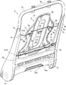
本発明の一つの実施の形態を図1〜6にしたがって説明する。図1に示すように車両用シート10は、使用者が着座するシートクッション11と、使用者の背中を支持するシートバック1を有している。シートクッション11とシートバック1の間には、シートバック1をシートクッション11に対してリクライニングさせるリクライニング装置14が設けられている。シートバック1の上部には、使用者の頭部を支持するヘッドレスト12が垂直方向に高さ調整可能に取付けられる。
One embodiment of the present invention will be described with reference to FIGS. As shown in FIG. 1, the
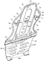
シートバック1は、図1に示すようにバックフレーム2と、パッド7と、パッド7の裏側を支持するプレート体3と、プレート体3をバックフレーム2に対して弾性的に保持する弾性サポート機構4を有している。バックフレーム2は、図2に示すように矩形枠状であって、左右のサイドフレーム2a,2bと、アッパーフレーム2cと、アンダーフレーム2dを有している。
As shown in FIG. 1, the
アッパーフレーム2cには、図2に示すように一対の筒部2eが設けられている。ヘッドレスト12は、筒部2eに対して上下に位置調整可能に挿入されるステー12aを有している(図1参照)。パッド7は、発砲ウレタン等の弾性変形する材料から形成されている。図5に示すようにパッド7は、所定の厚みを有しており、バックフレーム2の前側と側面を覆う。パッド7の表面には、表皮部材8が被せられる。
The
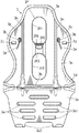
プレート体3は、図1に示すようにバックフレーム2よりも小さく、パッド7の裏側に配設される。プレート体3は、樹脂とガラス繊維を主成分に有する複合材料から成形されている。樹脂は、ナイロン6(PA6)などのポリアミド樹脂を使用し得る。ガラス繊維の重量は、複合材料の全重量の10〜20重量%である。プレート体3は、厚み約2mmの板状に形成されており、左右対称の形状を有している。図3に示すようにプレート体3は、上から順番に第一〜第五のプレート部3a〜3eを一体に有している。
As shown in FIG. 1, the
第一のプレート部3aは、図3,4に示すように大人の使用者の肩甲骨の高さにほぼ相当する高さに配設される。第一のプレート部3aは、肩甲骨を避けるように左右両側が窪んでおり、他のプレート部3b〜3eよりも幅が狭くなっている。例えば第一のプレート部3aは、第二のプレート部3bの幅の40〜60%の幅を有している。第三のプレート部3cは、使用者の腎臓に相当する高さに配設される。第三のプレート部3cは、使用者の腎臓を避けるように左右両側が窪んでおり、第二のプレート部3bよりも幅が狭くなっている。例えば第三のプレート部3cは、第二のプレート部3bの幅の70〜90%の幅を有している。
As shown in FIGS. 3 and 4, the
第四のプレート部3dは、使用者の腰椎の高さにほぼ相当する高さに配設される。そして他のプレート部3a〜3c,3eよりも幅が広く、例えば第三のプレート部3cの幅の140〜160%の幅を有している。第五のプレート部3eは、使用者の骨盤の高さにほぼ相当する高さに配設され、下側に斜めに幅が狭くなっている。
The
プレート体3は、図3,4に示すように幅中心位置に胸椎回避部3fを有している。胸椎回避部3fは、使用者の背骨の胸椎に対応する位置に形成されている。すなわちプレート体3の垂直方向の長さは、第一のプレート部3aの下側部から第四のプレート部3dの上側部に渡って長い。また胸椎回避部3fの幅は、胸椎よりも広く、40〜100mmの幅、好ましくは50±10mmの幅を有している。胸椎回避部3fは、上下位置に開口孔3f1,3f2を有し、開口孔3f1,3f2の間に凹部3f3を有している。
As shown in FIGS. 3 and 4, the
開口孔3f1,3f2は、図3,4に示すようにプレート体3を厚み方向に貫通している。上側の開口孔3f1は、第一のプレート部3aの下側部から第二のプレート部3bの略中心まで延出している。下側の開口孔3f2は、第三のプレート部3cの上下に渡って延出し、かつ第四のプレート部3dの上側部まで延出している。
As shown in FIGS. 3 and 4, the opening holes 3f1 and 3f2 penetrate the
凹部3f3は、図3,4に示すように開口孔3f1,3f2の間に位置している。凹部3f3は、胸椎から遠ざかるように、左右両側に後方に斜めに傾斜する傾斜部3f6と、傾斜部3f6間を連結する底部3f7を有している。凹部3f3は、例えば5〜10mmの深さを有している。凹部3f3は、第二のプレート部3bの下側部に位置し、第二のプレート部3bの下左部と下右部を連結する。そのため凹部3f3は、プレート体3が変形した際に開口孔3f1,3f2が左右に大きく開くことを防止する。
As shown in FIGS. 3 and 4, the recess 3f3 is located between the opening holes 3f1 and 3f2. The recessed portion 3f3 has an inclined portion 3f6 inclined obliquely rearward on both the left and right sides and a bottom portion 3f7 connecting the inclined portions 3f6 so as to be away from the thoracic vertebra. The recess 3f3 has a depth of 5 to 10 mm, for example. The recess 3f3 is located on the lower side of the
図2に示すように凹部3f3は、弾性サポート機構4の弾性架橋体5,6の間に位置している。そのためプレート体3が弾性架橋体5,6の間において後方に大きな力を受けた場合、開口孔3f2が左右に大きく開くことを凹部3f3によって防止できる。図3,4に示すように凹部3f3には、貫通孔3f4とリブ3f5が設けられている。貫通孔3f4は、横長さが縦長さに比べて長い。リブ3f5は、貫通孔3f4の上側位置において横方向に延出している。
As shown in FIG. 2, the
図3,4に示すようにプレート体3の裏面には、リブ3g,3h,3nが形成されている。リブ3gは、プレート体3の上側の外周、すなわち第一〜第四のプレート部3a〜3dの外周縁に形成されている。リブ3hは、第四のプレート部3dの裏面において横方向に延設されている。図2に示すようにリブ3hには、弾性サポート機構4のランバー用弾性架橋体6が挿通される。リブ3hと開口孔3f2の間には、開口孔3f2がリブ3hに接しないように、20±10mmの間隔が形成されている。その結果、プレート体3の剛性が高くなり、かつ開口孔3f2の端部の近傍における応力集中が小さくなる。
As shown in FIGS. 3 and 4,
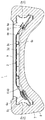
リブ3nは、図4に示すように胸椎回避部3fの左右両側において上下方向に延設されている。リブ3nの上端部は、第一のプレート部3aのリブ3gに達しており、下端部は、リブ3hよりも下側に延びている。
As shown in FIG. 4, the
第五のプレート部3eには、図3,4に示すように複数の開口部3e1が形成されている。開口部3e1は、横長さが縦長さより長く、上下に複数列配設されている。そして第五のプレート部3eの外周には、リブが形成されていない。そのため第五のプレート部3eは、厚み方向に変形しやすくかつ軽量になっている。第五のプレート部3eの下端部には、一対の爪3e2が形成されている。爪3e2は、図2に示すように軸部材14aに係止される。軸部材14aは、左右のリクライニング装置14を連結し、左右のリクライニング装置14を連動させる。
In the
図2に示すように弾性サポート機構4は、バックフレーム2に水平方向に架橋される一対の弾性架橋体5,6を有している。弾性架橋体5は、金属製で弾性力を有する棒状の部材であって、第二のプレート部3bの裏側に装着される。弾性架橋体5は、中心に屈曲部5aを有している。屈曲部5aの左右両側には、水平部5bと端部5cが設けられている。
As shown in FIG. 2, the
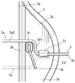
端部5cは、図2に示すようにサイドフレーム2a,2bに連結され、斜め下方に延出する。水平部5bは、端部5cから略水平方向に延出している。屈曲部5aは、図6に示すように第二のプレート部3bに沿ってかつ第一のプレート部3aに向けて屈曲している。この屈曲部5aは、左右の立ち上り部5a1と連結部5a2を有している。立ち上り部5a1は、水平部5bから第一のプレート部3aに向けて上方に延出している。連結部5a2は、略水平方向に延出して、左右の立ち上り部5a1を連結する。
As shown in FIG. 2, the
したがって弾性架橋体5は、第二のプレート部3bを弾性的に前後方向に移動可能に支持することができる。しかも弾性架橋体5は、屈曲部5aを有しているため、第一のプレート部3a側に加わる力をねじり力によって支持できる。
Therefore, the
第二のプレート部3bの裏面には、図2,6に示すように弾性架橋体5を保持するための鉤部3jと位置決め部3kが設けられている。鉤部3jは、弾性架橋体5の水平部5bが下側から差し込まれる開口部3j1を有している。位置決め部3kは、弾性架橋体5の立ち上り部5a1と連結部5a2のコーナーの内側に突出している。したがって鉤部3jと位置決め部3kによって弾性架橋体5の上下方向の移動を規制する。そして一対の位置決め部3kによって弾性架橋体5の左右方向の移動を規制する。かくして弾性架橋体5は、プレート体3に安定良く保持され得る。
On the back surface of the
第二のプレート部3bの裏面には、図2,6に示すように誤組付防止用突部3mが形成されている。誤組付防止用突部3mは、位置決め部3kの下側位置に形成されており、位置決め部3kから斜め下方に延出している。したがって弾性架橋体5を第二のプレート部3bに組付ける際に、屈曲部5aが第三のプレート部3cに向いた状態になることを誤組付防止用突部3mによって防止できる。かくして誤組付防止用突部3mによって弾性架橋体5を正しく第二のプレート部3bに組付けることができる。
As shown in FIGS. 2 and 6, a
図2に示すように弾性架橋体5は、リブ3nの裏側に配設され、左右のリブ3nに跨って延出している。そのため弾性架橋体5は、リブ3nの高さと同じ距離、開口孔3f1から後方に位置している。そのためプレート体3が弾性変形した場合に、弾性架橋体5が開口孔3f1を通って使用者の胸椎に押圧を加えてしまうことが防止され得る。
As shown in FIG. 2, the
弾性架橋体6は、図2に示すように第四のプレート部3dのリブ3hに沿って設けられる。弾性架橋体6は、図2,5に示すように一対のコイルスプリング6aと、ワイヤ6bを有している。一対のコイルスプリング6aの一端部は、サイドフレーム2a,2bに係止される。一つのコイルスプリング6aの他端部には、ワイヤ6bの先端を保持する保持部6dが取付けられる。他のコイルスプリング6aの他端部には、ワイヤ6bが挿通される外管6cが取付けられる。そしてワイヤ6bは、保持部6dからリブ3hの中を通って、外管6cに挿通され、これによって一対のコイルスプリング6aの間に張設される。
The
ワイヤ6bと外管6cは、図1に示すように車両用シート10内に取回され、ワイヤ6bの一端部が巻取り部13に取付けられる。巻取り部13は、シートクッション11の側部に取付けられており、時計回りに軸回転することでワイヤ6bを外管6cに対して巻取る。逆に、反時計回りに軸回転することでワイヤ6bを外管6cに対して放出する。したがって一対のコイルスプリング6a間のワイヤ6b長さが巻取り部13によって調整される。そしてワイヤ6bの長さを調整することで、ランバー用弾性架橋体6の全長が調整され得る。
As shown in FIG. 1, the
図2に示すようにプレート体3は、上部が弾性架橋体5によってバックフレーム2に対して位置保持され、下端部が爪3e2によって位置保持される。そのためプレート体3は、前後方向の位置が弾性架橋体5と爪3e2によって支持される。一方、ランバー用弾性架橋体6のコイルスプリング6aは、弾性架橋体5と爪3e2よりも前側に位置するようにバックフレーム2に取付けられる。そのためランバー用弾性架橋体6は、長さが短くなることで第四のプレート部3dを前方に押す。そしてランバー用弾性架橋体6が長くなることで、第四のプレート部3dが後方に移動する。したがってランバー用弾性架橋体6の長さの調節によってプレート体3を使用者の体型に合わせて変形させ得る。
As shown in FIG. 2, the
ランバー用弾性架橋体6は、長さ調整した後、コイルスプリング6aによってプレート体3を弾性的に前後移動可能に保持する。図5に示すようにシートバック1の後面は、保護板9によって覆われ、保護板9によってプレート体3と弾性サポート機構4の裏側が覆い隠される。そしてプレート体3の前側にパッド7が設置され、パッド7が表皮部材8によって覆われる。
After the length of the lumbar
以上のように、プレート体3は、図3に示すように車両用シート10に着座した使用者の胸椎を押すことを避けるために、開口孔3f1,3f2と凹部3f3を備える胸椎回避部3fを有している。そして胸椎回避部3fは、プレート体3の幅略中心位置にて上下方向に長く、かつ40〜100mmの幅を有している。
As described above, the
したがって胸椎回避部3fが開口孔3f1,3f2と凹部3f3を有するため、プレート体3による使用者の胸椎への押圧力が解消(減少)され得る。しかも胸椎回避部3fは、幅略中心位置にて上下方向に長く、かつ40〜100mmの幅を有している。そのため使用者の胸椎への押圧力を十分に抑制でき、これによって車両用シート10の座り心地が向上し得る。
Therefore, since the thoracic
また胸椎回避部3fは、図3に示すように上下位置に開口孔3f1,3f2を有しており、かつ開口孔3f1,3f2の間に凹部3f3を有している。したがって開口孔3f1,3f2を有しているためにプレート体3が軽量になる。そして開口孔3f1,3f2と凹部3f3を有しているために胸椎への押圧力が十分に小さくなる。また上下の開口孔3f1,3f2の間に凹部3f3を有しているために、凹部3f3によってプレート体3の大きな変形を防止することができる。特にプレート体3の開口孔3f1,3f2が大きく変形することを防止することができる。例えば、シートバック1を後方に大きく倒した状態で、開口孔3f1,3f2の上方に乗員が膝をつく行動をしたとしても、プレート体3によるパッド7の支持強度が不足する事態を防ぐことができる。したがって凹部3f3によってプレート体3の強度が強くなる。
As shown in FIG. 3, the thoracic
また図3に示すようにプレート体3は、胸椎回避部3fの左右側において上下方向に延設されるリブ3nを有している。そのためプレート体3は、胸椎回避部3fの周囲が開口孔3f1,3f2を有するために他の部分に比べて弱いが、その部分がリブ3nによって補強され得る。しかもリブ3nは、胸椎回避部3fの左右位置において上下に延出している。そのためプレート体3は、リブ3nによって胸椎回避部3fの周りが確実かつ効率良く補強され得る。
As shown in FIG. 3, the
また弾性サポート機構4は、図2に示すようにプレート体3の上部裏側と下部裏側においてバックフレーム2に水平方向に架橋される一対の弾性架橋体5,6を有している。そしてリブ3nは、一対の弾性架橋体5,6に渡って延出している。したがって一方の弾性架橋体5,6に加わった力は、リブ3nによって他方の弾性架橋体5,6に伝達され得る。そのため弾性サポート機構4やプレート体3の一部に力が集中することをリブ3nによって避けることができる。
2, the
本発明は、上記実施の形態に限定されず、以下の形態であっても良い。
(1)例えば上記実施の形態の弾性サポート機構4は、図2に示すようにバックフレーム2に水平方向に架橋される弾性架橋体5,6を有している。しかし弾性サポート機構が複数のばねを有しており、ばねの一端部がプレート体の端部に係止され、他端部がバックフレームに連結される形態であっても良い。
(2)上記実施の形態の弾性架橋体5,6は、図2に示すようにバックフレーム2に水平方向に架橋される形態である。しかし弾性架橋体がバックフレームに上下方向に架橋される形態であっても良い。
(3)上記実施の形態のランバー用弾性架橋体6は、図5に示すように長さ調整されて第四のプレート部3dを前後に位置調整する形態である。しかし位置調整できない形態、例えばランバー用弾性架橋体が弾性架橋体5と同じように棒状の形態であっても良い。
(4)上記実施の形態の胸椎回避部3fは、図3に示すように上下位置に開口孔3f1,3f2を有し、中心位置に凹部3f3を有している。しかし胸椎回避部が開口部のみから形成される形態、もしくは凹部のみから形成される形態、もしくは三つ以上の開口孔とこれら開口孔の間に位置する凹部から形成される形態であっても良い。
(5)上記実施の形態の弾性サポート機構4は、図2に示すように一対の弾性架橋体5,6を有している。しかし弾性サポート機構が三本以上の弾性架橋体を有する形態であっても良い。
The present invention is not limited to the above-described embodiment, and may be the following form.
(1) For example, the
(2) The
(3) The lumbar elastic bridged
(4) As shown in FIG. 3, the thoracic
(5) The
1…シートバック
2…バックフレーム(フレーム)
3…プレート体
3a…第一のプレート部
3b…第二のプレート部
3c…第三のプレート部
3d…第四のプレート部
3e…第五のプレート部
3e2…爪
3f…胸椎回避部
3f1,3f2…開口孔
3f3…凹部
3f4…貫通孔
3f5,3g,3h,3n…リブ
3m…誤組付防止用突部
4…弾性サポート機構
5…弾性架橋体
6…ランバー用弾性架橋体(弾性架橋体)
7…パッド
8…表皮部材
9…保護板
10…車両用シート
11…シートクッション
1 ... Seat back 2 ... Back frame (frame)
3 ...
7 ...
Claims (6)
前記パッドの裏面を支持するプレート体と、
前記プレート体を前記フレームに対して前後に移動可能に弾性的に保持する弾性サポート機構とを有し、
前記プレート体は、車両用シートに着座した使用者の胸椎を押すことを避けるために、開口孔もしくは前記車両用シートに着座した使用者の胸椎から遠ざかる方向に窪む凹部のいずれか少なくとも一つを備える胸椎回避部を有し、
前記胸椎回避部は、前記プレート体の幅略中心位置にて上下方向に長く、かつ40〜100mmの幅を有し、
前記胸椎回避部は、上下位置に前記開口孔を有し、かつこれら開口孔の間に前記凹部を有し、
前記凹部は、前記胸椎回避部の左右両側の前記プレート体の左部と右部を連結している車両用シートのシートバック。 A vehicle seat back having a pad and a frame,
A plate body for supporting the back surface of the pad;
An elastic support mechanism that elastically holds the plate body movably back and forth with respect to the frame;
In order to avoid pushing the thoracic vertebra of the user seated on the vehicle seat, the plate body is at least one of an opening hole or a recess recessed in a direction away from the thoracic vertebra of the user seated on the vehicle seat. A thoracic vertebra avoidance section comprising
The thoracic vertebra avoidance part is long in the vertical direction at a substantially central position of the plate body, and has a width of 40 to 100 mm ,
The thoracic vertebra avoidance part has the opening hole in the vertical position, and has the recess between these opening holes,
The concave portion is a seat back of a vehicle seat that connects a left portion and a right portion of the plate body on both left and right sides of the thoracic vertebra avoidance portion .
前記プレート体は、前記胸椎回避部の少なくとも左右いずれか側において上下方向に延設されるリブを有している車両用シートのシートバック。 A vehicle seat back according to claim 1 ,
The plate body is a seat back of a vehicle seat having a rib extending in a vertical direction on at least one of the left and right sides of the thoracic vertebra avoidance portion.
前記弾性サポート機構は、前記プレート体の上裏部と下裏部において前記フレームに水平方向に架橋される一対の弾性架橋体を有し、
前記リブは、前記一対の弾性架橋体に渡って垂直方向に延出している車両用シートのシートバック。 A vehicle seat back according to claim 2 ,
The elastic support mechanism has a pair of elastic cross-linked bodies that are cross-linked in the horizontal direction to the frame at the upper back and lower back of the plate body,
The rib is a seat back of a vehicle seat that extends in a vertical direction across the pair of elastic bridges.
前記凹部は、上下方向において前記一対の弾性架橋体の間に位置し、かつ左右方向において前記胸椎回避部の左右に位置する左右の前記リブの間に位置する車両用シートのシートバック。 A vehicle seat back according to claim 3,
The seat recess of the vehicle seat positioned between the pair of elastic bridges in the vertical direction and between the left and right ribs positioned on the left and right of the thoracic vertebra avoidance unit in the horizontal direction.
前記プレート体は、ポリアミド樹脂とガラス繊維とを含む複合材料から成形されている車両用シートのシートバック。 The vehicle seat back according to any one of claims 1 to 4,
The plate body is a seat back of a vehicle seat formed from a composite material including a polyamide resin and glass fibers.
前記弾性サポート機構は、前記フレームに水平方向に架橋される複数の弾性架橋体を有し、
一つの前記弾性架橋体は、長さ調整可能であって、長さ調整することで前記プレート体の一部を前後方向に位置調整する車両用シートのシートバック。
A seat back of a vehicle seat according to any one of claims 1 to 5,
The elastic support mechanism has a plurality of elastic cross-linked bodies that are cross-linked in the horizontal direction to the frame,
One of the elastic cross-linked bodies is a seat back of a vehicle seat that can be adjusted in length and adjusts the position of a part of the plate body in the front-rear direction.
Applications Claiming Priority (2)
| Application Number | Priority Date | Filing Date | Title |
|---|---|---|---|
| US11/875255 | 2007-10-19 | ||
| US11/875,255 US7575278B2 (en) | 2007-10-19 | 2007-10-19 | Seat backs for vehicular seats |
Publications (2)
| Publication Number | Publication Date |
|---|---|
| JP2009101137A JP2009101137A (en) | 2009-05-14 |
| JP5259309B2 true JP5259309B2 (en) | 2013-08-07 |
Family
ID=40562755
Family Applications (1)
| Application Number | Title | Priority Date | Filing Date |
|---|---|---|---|
| JP2008227281A Expired - Fee Related JP5259309B2 (en) | 2007-10-19 | 2008-09-04 | Seat back of vehicle seat |
Country Status (2)
| Country | Link |
|---|---|
| US (1) | US7575278B2 (en) |
| JP (1) | JP5259309B2 (en) |
Families Citing this family (19)
| Publication number | Priority date | Publication date | Assignee | Title |
|---|---|---|---|---|
| JP4643480B2 (en) * | 2006-03-23 | 2011-03-02 | トヨタ自動車株式会社 | Vehicle seat back frame |
| JP4925176B2 (en) * | 2006-07-07 | 2012-04-25 | テイ・エス テック株式会社 | Vehicle seat |
| EP2390131A1 (en) * | 2009-01-21 | 2011-11-30 | TS Tech Co., Ltd. | Vehicle seat |
| JP5085603B2 (en) * | 2009-04-24 | 2012-11-28 | 本田技研工業株式会社 | Seat back device |
| JP5570776B2 (en) * | 2009-09-24 | 2014-08-13 | トヨタ紡織株式会社 | Vehicle seat |
| US8215695B2 (en) * | 2009-11-09 | 2012-07-10 | Toyota Boshoku Kabushiki Kaisha | Removable vehicle seat |
| JP5513212B2 (en) | 2010-03-30 | 2014-06-04 | 日本発條株式会社 | Vehicle seat back and vehicle seat provided with the same |
| JP5513213B2 (en) | 2010-03-30 | 2014-06-04 | 日本発條株式会社 | Vehicle seat back and vehicle seat provided with the same |
| KR101209933B1 (en) * | 2010-11-29 | 2012-12-10 | 현대자동차주식회사 | Suspension assembly of seat for vehicle |
| EP2628634B1 (en) * | 2010-12-24 | 2016-04-27 | Honda Motor Co., Ltd. | Vehicle seat back structure |
| US9802521B2 (en) * | 2015-03-31 | 2017-10-31 | Ford Global Technologies, Llp | Multilayer seat |
| DE102016205472A1 (en) * | 2016-04-01 | 2017-10-05 | Ford Global Technologies, Llc | Upholstery element for a vehicle seat |
| US10251487B2 (en) | 2016-11-01 | 2019-04-09 | Lear Corporation | Seat assembly having a thoracic support mechanism |
| EP3657989B1 (en) * | 2017-07-28 | 2021-09-01 | Inter-Face Medical LLC | Lower back and posture support device |
| US10668842B2 (en) * | 2018-08-16 | 2020-06-02 | Sears Manufacturing Co. | Adjustable lumbar support for a vehicle seat |
| JP7294786B2 (en) * | 2018-10-05 | 2023-06-20 | トヨタ自動車株式会社 | vehicle seat |
| JP6880422B2 (en) * | 2019-11-25 | 2021-06-02 | テイ・エス テック株式会社 | Vehicle seat |
| USD1025655S1 (en) * | 2022-03-25 | 2024-05-07 | Jingxue Chen | Ergonomic lumbar support |
| CN117644806B (en) * | 2024-01-29 | 2024-04-02 | 宁波市鄞州宏波汽车零部件有限公司 | Rear seat frame |
Family Cites Families (22)
| Publication number | Priority date | Publication date | Assignee | Title |
|---|---|---|---|---|
| JPS5646607Y2 (en) * | 1977-08-11 | 1981-10-30 | ||
| US5044693A (en) * | 1989-10-31 | 1991-09-03 | Tachi-S Co., Ltd. | Seat back structure of an automotive seat |
| DE4232679C1 (en) * | 1992-09-29 | 1994-02-03 | Ameu Management Corp Luxembour | Backrest of a seat with an adjustment device for an elastic arch element for adjusting the curvature of the backrest |
| US5518294A (en) * | 1993-04-05 | 1996-05-21 | Ligon Brothers Manufacturing Company | Variable apex back support |
| US5577811A (en) * | 1995-06-07 | 1996-11-26 | Hon Industries Inc. | Ergonomic chair |
| WO2000047086A1 (en) | 1999-02-12 | 2000-08-17 | Schukra Manufacturing Inc. | Adjustable back support for seats |
| GB0106247D0 (en) * | 2001-03-14 | 2001-05-02 | Williams David N L | Improvements relating to supports |
| MXPA04000313A (en) | 2001-07-11 | 2005-03-07 | Alfmeier Corp | Integrated adjustable lumbar support and trim attachment system. |
| KR100438100B1 (en) * | 2002-01-26 | 2004-07-02 | 홍정명 | Lumber Support for a Car Seat |
| WO2003095262A2 (en) * | 2002-05-08 | 2003-11-20 | Alfmeier Corporation | Adjustable floating plate lumbar support |
| JP4078122B2 (en) | 2002-05-30 | 2008-04-23 | ジョンソン コントロールズ オートモーティブ システムズ株式会社 | Automotive seat back |
| US20040080197A1 (en) * | 2002-10-25 | 2004-04-29 | Robert Kopetzky | Transmission amplifier for bowden cables and method of using the same |
| US7052087B2 (en) * | 2002-12-09 | 2006-05-30 | L&P Property Management Company | Method and apparatus for a scissors ergonomic support |
| ITMI20030446A1 (en) * | 2003-03-11 | 2004-09-12 | Resal S R L | ANATOMICAL STRUCTURE WITH FRAME AND CONVEX SHEET-CUSHION FOR BACKRESTS, HEADRESTS AND SEATS OF ARMCHAIRS IN GENERAL, ESPECIALLY FOR MOTOR VEHICLES WITH MANUAL AND MOTORIZED ADJUSTMENT OF THE CONVEX AND THE POSITION OF THE SHEET-CUSHION. |
| US7097247B2 (en) * | 2003-06-05 | 2006-08-29 | Steelcase Development Corporation | Seating unit with adjustable lumbar device |
| US7140681B2 (en) * | 2003-09-03 | 2006-11-28 | L&P Property Management Company | Occupant centering ergonomic support apparatus and method |
| US7165810B2 (en) * | 2004-05-28 | 2007-01-23 | L&P Property Management Company | Low cost lever acutator apparatus and method |
| JP4442876B2 (en) | 2004-07-06 | 2010-03-31 | テイ・エス テック株式会社 | Vehicle seat |
| EP1890573A4 (en) * | 2005-05-18 | 2009-03-18 | Schukra North America Ltd | Dual hinge belt lumbar |
| US7425036B2 (en) * | 2005-08-23 | 2008-09-16 | Schukra Of North America, Ltd. | Comfort belt spring pulley |
| DE102006015523A1 (en) * | 2006-03-31 | 2007-10-04 | Recaro Aircraft Seating Gmbh & Co. Kg | seat device |
| US7399036B2 (en) * | 2006-12-01 | 2008-07-15 | Sabic Innovative Plastics Ip B.V. | Molded plastic universal seat |
-
2007
- 2007-10-19 US US11/875,255 patent/US7575278B2/en active Active
-
2008
- 2008-09-04 JP JP2008227281A patent/JP5259309B2/en not_active Expired - Fee Related
Also Published As
| Publication number | Publication date |
|---|---|
| US20090102258A1 (en) | 2009-04-23 |
| JP2009101137A (en) | 2009-05-14 |
| US7575278B2 (en) | 2009-08-18 |
Similar Documents
| Publication | Publication Date | Title |
|---|---|---|
| JP5259309B2 (en) | Seat back of vehicle seat | |
| JP5259310B2 (en) | Seat back of vehicle seat | |
| JP4737501B2 (en) | Vehicle seat | |
| JP5365167B2 (en) | Vehicle seat cushion | |
| KR101678400B1 (en) | Vehicle seat with a lumbar support | |
| US20110241403A1 (en) | Seat back for vehicle and seat for vehicle including the same | |
| CN103260947B (en) | Vehicle seat used seat cushion | |
| JP7112005B2 (en) | seat | |
| JP4728669B2 (en) | Seat back frame for automobile seat | |
| KR102130324B1 (en) | Assembly and chair with the same | |
| US6371561B1 (en) | Frame structure for a seatback of a seat | |
| JP4728670B2 (en) | Automotive seat backrest frame | |
| CN102069735A (en) | Vehicle seat | |
| JP2004290605A (en) | Backrest seat for vehicle seat | |
| JP2019059311A (en) | Vehicle seat | |
| JP2009106346A (en) | Chair | |
| JP2020158097A (en) | Vehicle seat | |
| JP2006026011A (en) | Seat | |
| KR101999725B1 (en) | Suspension apparatus for vehicle seat | |
| JPH0975169A (en) | Lumbar support structure for automobile seat back | |
| JP2006088875A (en) | Vehicle seat | |
| JPH10151036A (en) | Seat back device | |
| JP2009106345A (en) | Chair | |
| JP2018075079A (en) | Load support member for chair, and chair | |
| JP2000316665A (en) | Vehicle seat cushion |
Legal Events
| Date | Code | Title | Description |
|---|---|---|---|
| A621 | Written request for application examination |
Free format text: JAPANESE INTERMEDIATE CODE: A621 Effective date: 20110519 |
|
| A131 | Notification of reasons for refusal |
Free format text: JAPANESE INTERMEDIATE CODE: A131 Effective date: 20130115 |
|
| A977 | Report on retrieval |
Free format text: JAPANESE INTERMEDIATE CODE: A971007 Effective date: 20130117 |
|
| A521 | Request for written amendment filed |
Free format text: JAPANESE INTERMEDIATE CODE: A523 Effective date: 20130305 |
|
| TRDD | Decision of grant or rejection written | ||
| A01 | Written decision to grant a patent or to grant a registration (utility model) |
Free format text: JAPANESE INTERMEDIATE CODE: A01 Effective date: 20130402 |
|
| A61 | First payment of annual fees (during grant procedure) |
Free format text: JAPANESE INTERMEDIATE CODE: A61 Effective date: 20130424 |
|
| FPAY | Renewal fee payment (event date is renewal date of database) |
Free format text: PAYMENT UNTIL: 20160502 Year of fee payment: 3 |
|
| R150 | Certificate of patent or registration of utility model |
Ref document number: 5259309 Country of ref document: JP Free format text: JAPANESE INTERMEDIATE CODE: R150 Free format text: JAPANESE INTERMEDIATE CODE: R150 |
|
| R250 | Receipt of annual fees |
Free format text: JAPANESE INTERMEDIATE CODE: R250 |
|
| R250 | Receipt of annual fees |
Free format text: JAPANESE INTERMEDIATE CODE: R250 |
|
| R250 | Receipt of annual fees |
Free format text: JAPANESE INTERMEDIATE CODE: R250 |
|
| R250 | Receipt of annual fees |
Free format text: JAPANESE INTERMEDIATE CODE: R250 |
|
| LAPS | Cancellation because of no payment of annual fees |