JP5259274B2 - Fixture mount fixture - Google Patents
Fixture mount fixture Download PDFInfo
- Publication number
- JP5259274B2 JP5259274B2 JP2008171821A JP2008171821A JP5259274B2 JP 5259274 B2 JP5259274 B2 JP 5259274B2 JP 2008171821 A JP2008171821 A JP 2008171821A JP 2008171821 A JP2008171821 A JP 2008171821A JP 5259274 B2 JP5259274 B2 JP 5259274B2
- Authority
- JP
- Japan
- Prior art keywords
- fixture
- mount
- storage container
- fixture mount
- hole
- Prior art date
- Legal status (The legal status is an assumption and is not a legal conclusion. Google has not performed a legal analysis and makes no representation as to the accuracy of the status listed.)
- Expired - Fee Related
Links
- 210000000214 mouth Anatomy 0.000 claims description 21
- 238000003780 insertion Methods 0.000 claims description 16
- 230000037431 insertion Effects 0.000 claims description 16
- 238000010079 rubber tapping Methods 0.000 claims description 15
- NJPPVKZQTLUDBO-UHFFFAOYSA-N novaluron Chemical compound C1=C(Cl)C(OC(F)(F)C(OC(F)(F)F)F)=CC=C1NC(=O)NC(=O)C1=C(F)C=CC=C1F NJPPVKZQTLUDBO-UHFFFAOYSA-N 0.000 claims description 13
- 239000007943 implant Substances 0.000 claims description 9
- 238000012423 maintenance Methods 0.000 claims 1
- 239000004053 dental implant Substances 0.000 description 2
- 238000010586 diagram Methods 0.000 description 1
- 238000002513 implantation Methods 0.000 description 1
Images


Classifications
-
- A—HUMAN NECESSITIES
- A61—MEDICAL OR VETERINARY SCIENCE; HYGIENE
- A61C—DENTISTRY; APPARATUS OR METHODS FOR ORAL OR DENTAL HYGIENE
- A61C8/00—Means to be fixed to the jaw-bone for consolidating natural teeth or for fixing dental prostheses thereon; Dental implants; Implanting tools
- A61C8/0089—Implanting tools or instruments
-
- A—HUMAN NECESSITIES
- A61—MEDICAL OR VETERINARY SCIENCE; HYGIENE
- A61C—DENTISTRY; APPARATUS OR METHODS FOR ORAL OR DENTAL HYGIENE
- A61C8/00—Means to be fixed to the jaw-bone for consolidating natural teeth or for fixing dental prostheses thereon; Dental implants; Implanting tools
- A61C8/0087—Means for sterile storage or manipulation of dental implants
Landscapes
- Health & Medical Sciences (AREA)
- Oral & Maxillofacial Surgery (AREA)
- Orthopedic Medicine & Surgery (AREA)
- Dentistry (AREA)
- Epidemiology (AREA)
- Life Sciences & Earth Sciences (AREA)
- Animal Behavior & Ethology (AREA)
- General Health & Medical Sciences (AREA)
- Public Health (AREA)
- Veterinary Medicine (AREA)
- Dental Prosthetics (AREA)
- Details Of Rigid Or Semi-Rigid Containers (AREA)
Description
本発明は、歯科用インプラント治療に用いられるフィクスチャーマウントに装着しフィクスチャーマウントを回転不能状態に維持させることによって、フィクスチャーマウントが係合されたセルフタッピング式インプラントフィクスチャー(以下、「フィクスチャー」と言う)を収納容器内で回転不能な状態にして、フィクスチャーマウントとフィクスチャーとをボルト締めする際にフィクスチャーが収納容器内で回転して損傷することを防止するためのフィクスチャーマウント固定具に関する。 The present invention is a self-tapping implant fixture (hereinafter referred to as “fixture”) to which a fixture mount is engaged by being attached to a fixture mount used for dental implant treatment and maintaining the fixture mount in a non-rotatable state. Fixture mount to prevent the fixture from rotating and damaging in the storage container when bolting the fixture mount and fixture. It relates to a fixture.
歯科用インプラント治療に使用されるフィクスチャーは実際に使用されるまで滅菌状態を保ったままの状態に収納する専用の収納容器に収納されている。 The fixture used for the dental implant treatment is stored in a dedicated storage container that is stored in a sterilized state until it is actually used.
このように専用の収納容器に収納されたフィクスチャーは、欠損歯部の顎骨内に埋入させるための回転駆動力が伝達される埋入用インスツルメントをその口腔内側の穴に装着され、この埋入用インスツルメントを介して収納容器内から取り出される。この埋入用インスツルメントとしては、フィクスチャーの中心軸に沿って穿設され反口腔内側に向かって先端が閉ざされためねじ部が螺設されている穴の口腔側内面に形成された複数の凹条溝に係合される複数の係合用突起が先端部に形成されていて、このフィクスチャーの口腔側内面に形成された複数の凹条溝に先端部に形成されている複数の係合用突起を係合させることによってフィクスチャーへの回転駆動力の伝達が可能であると共に、フィクスチャーを保持することも可能にするものがある(例えば、特許文献1参照。)。 In this way, the fixture stored in the dedicated storage container is attached to the hole on the inner side of the oral cavity with an insertion instrument that transmits a rotational driving force for insertion into the jawbone of the missing tooth part, It is taken out from the storage container through this instrument for embedding. As this instrument for implantation, a plurality of holes formed along the central axis of the fixture and formed on the inner surface of the oral cavity side of the hole in which the tip is closed toward the inner side of the oral cavity and the screw portion is screwed. A plurality of engaging protrusions that are engaged with the concave grooves are formed at the tip, and a plurality of engagement protrusions formed at the tip are formed on the plurality of concave grooves formed on the oral cavity inner surface of the fixture. There is one that can transmit the rotational driving force to the fixture by engaging the fitting protrusion, and can also hold the fixture (see, for example, Patent Document 1).
この埋入用インスツルメントのフィクスチャーの口腔内側の穴への係合は、その先端をフィクスチャーに穿設された穴の口腔内側に押し当てて、フィクスチャーの凹条溝と埋入用インスツルメントの係合用突起との位置が合致するまで埋入用インスツルメントを回転させた後に埋入用インスツルメントの係合用突起をフィクスチャーの凹条溝内に挿入させることによって行われる。その際に、埋入用インスツルメントの先端が押し当てられたフィクスチャーが一緒に回転すると埋入用インスツルメントをフィクスチャーに係合させることができないので、収納容器内の奥側に突起部を形成させ、この突起部にフィクスチャーの先端側のセルフタッピングねじに形成された切り刃部に沿って設けられた溝部を当接させて収納容器内でフィクスチャーを回転不能にさせているのである。 Engage the fixture of the implantable instrument with the hole inside the oral cavity by pressing its tip against the inside of the oral cavity of the hole drilled in the fixture, This is done by rotating the implantable instrument until the position of the instrument's engaging protrusion matches with that of the instrument, and then inserting the engaging protrusion of the embedded instrument into the recessed groove of the fixture. . At that time, if the fixture against which the tip of the embedding instrument is pressed rotates together, the embedding instrument cannot be engaged with the fixture. And a groove provided along the cutting edge formed on the self-tapping screw on the distal end side of the fixture is brought into contact with the protrusion so that the fixture cannot be rotated in the storage container. It is.
このような収納容器と埋入用インスツルメントとを利用すれば、フィクスチャーに直接触れることなく、埋入用インスツルメントを介してフィクスチャーを簡便に取り扱うことができるが、前記埋入用インスツルメントはフィクスチャーに係合されているだけであるため、外れ易いという問題がある。そこでその先端をフィクスチャーの口腔内側の端部に係合できるだけでなく、確実に固定できるものとして、フィクスチャーの係合部の奥部に形成されためねじ部へと繋がる貫通穴を通して螺入されたボルトによってフィクスチャーに固定することができるフィクスチャーマウントが使用されるようになってきた。 If such a storage container and an instrument for embedding are used, the fixture can be easily handled through the instrument for embedding without directly touching the fixture. Since the instrument is only engaged with the fixture, there is a problem that the instrument is easily detached. Therefore, the tip of the fixture is not only engaged with the end of the oral cavity, but can also be fixed securely, so that it is screwed through a through-hole that is formed at the back of the engagement portion of the fixture and leads to the screw portion. Fixture mounts that can be fixed to the fixture with bolts have come to be used.
このフィクスチャーマウントをフィクスチャーに係合させるには、フィクスチャーマウントの先端をフィクスチャーに穿設された穴の口腔内側に押し当てて、フィクスチャーマウントの先端がフィクスチャーに穿設された穴に挿入できる状態となるまでフィクスチャーマウントを回転させて挿入係合させなければならないため、埋入用インスツルメントの場合と同様に収納容器内の奥側に突起部を形成させてフィクスチャーが回転しないようにする必要がある。 To engage this fixture mount with the fixture, press the tip of the fixture mount against the inside of the oral cavity of the hole drilled in the fixture, and the hole where the tip of the fixture mount was drilled in the fixture Since the fixture mount must be rotated and engaged until it can be inserted into the storage container, a protrusion is formed on the back side of the storage container in the same manner as in the case of the embedded instrument. It is necessary not to rotate.
このように、奥側に突起部が形成されている収納容器と、貫通穴を有するフィクスチャーマウントとを使用すれば、フィクスチャーマウントとフィクスチャーとがボルトによって完全に一体化されてフィクスチャーがフィクスチャーマウントから脱落することがない状態でインプラント治療を行えるのである。 In this way, if a storage container having a protrusion on the back side and a fixture mount having a through hole are used, the fixture mount and the fixture are completely integrated by bolts, and the fixture is The implant treatment can be performed without falling off the fixture mount.
しかしながら、ボルトによってフィクスチャーマウントをフィクスチャーに固定する際に、ドライバー等でボルトを締めるためにフィクスチャーに必要以上に大きなトルクが加えられると、フィクスチャーマウントとフィクスチャーとが一体となって回転して、フィクスチャーの先端部が収納容器内奥側の突起部に強く当接してフィクスチャーの先端が損傷するという現象が発生するという問題がある。
このような現象は、フィクスチャーマウントを保持した状態でボルトを締め付ければ発生しないのであるが、フィクスチャーマウントは小さくて持ちにくいので、収納容器を持ってボルト締めすると、フィクスチャーとフィクスチャーマウントとが一緒に回転してフィクスチャーの先端が納容器内の奥側に突起部に強く当接して損傷するという現象が発生するのである。
However, when the fixture mount is fixed to the fixture with bolts, the fixture mount and the fixture rotate together if a larger torque is applied to the fixture to tighten the bolt with a screwdriver. As a result, there is a problem in that a phenomenon occurs in which the front end of the fixture strongly contacts the protrusion on the inner side of the storage container and the front end of the fixture is damaged.
This phenomenon does not occur if the bolt is tightened while holding the fixture mount, but the fixture mount is small and difficult to hold, so if you hold the storage container and tighten the bolt, the fixture and fixture mount This causes a phenomenon that the tip of the fixture is damaged due to strong contact with the protrusion on the back side in the container.
本発明は前記の問題に鑑み、フィクスチャーマウントに装着しフィクスチャーマウントを回転不能状態に維持させることによって、フィクスチャーマウントが係合されたフィクスチャーを収納容器内で回転不能な状態にして、フィクスチャーマウントをフィクスチャーにボルト締めする際にフィクスチャーが収納容器内で回転して損傷することを防止するためのフィクスチャーマウント固定具を提供することを課題とする。 In view of the above problems, the present invention makes the fixture engaged with the fixture mount non-rotatable in the storage container by mounting the fixture mount and maintaining the fixture mount in a non-rotatable state. It is an object of the present invention to provide a fixture mount fixture for preventing the fixture from rotating and being damaged in the storage container when the fixture mount is bolted to the fixture.
本発明者らは前記課題を解決すべく鋭意検討した結果、フィクスチャーが収納された収納容器に対してフィクスチャーマウントを回転不能状態に維持させるために装着されるフィクスチャーマウント固定具を、中央にボルトを挿通させるボルト挿通用貫通穴が穿設されている頂部と頂部から収納容器の側面に向けて垂下された垂下部とから構成させ、頂部のボルト挿通用貫通穴をフィクスチャーマウントの口腔内側の端部外面に設けられている正多角形状部に係合する係合穴を有しているか、及び/又は垂下部にフィクスチャーマウントの側面に設けられている中心軸と平行な平面部に当接する係合面を有している形状に形成すれば、フィクスチャーと係合させたフィクスチャーマウントにフィクスチャーマウント固定具を装着することによって、フィクスチャーとフィクスチャーマウントとフィクスチャーマウント固定具とが一体となり、更に収納容器を保持する台座に収納容器保持穴を設けるか又は収納容器の側面に形成されている係合部に係止される係止部を垂下部に設け、フィクスチャーマウント固定具を台座又は収納容器に固定させれば、フィクスチャーマウント固定具と一体となっているフィクスチャーマウント及びフィクスチャーも回転不能な状態となるから、この状態でフィクスチャーマウントとフィクスチャーとをボルトで固定すれば、ボルトを締め付ける際にフィクスチャーが収納容器内で回転してフィクスチャーの先端部が収納容器内奥側の突起部に強く当接して損傷する現象が発生することがないことを究明して本発明を完成したのである。 As a result of intensive studies to solve the above problems, the present inventors have determined that the fixture mount fixture to be mounted to keep the fixture mount in a non-rotatable state with respect to the storage container in which the fixture is stored, A bolt insertion through hole for allowing the bolt to pass through and a hanging part hanging from the top toward the side of the storage container, and the bolt insertion through hole at the top of the fixture mount A plane part that has an engagement hole that engages with a regular polygonal part provided on the outer surface of the inner end and / or is parallel to the central axis provided on the side surface of the fixture mount at the hanging part If the fixture mount is engaged with the fixture, the fixture mount fixture is attached to the fixture mount. The fixture, the fixture mount, and the fixture mount fixture are integrated, and further, a storage container holding hole is provided in the pedestal for holding the storage container, or it is locked to the engaging portion formed on the side surface of the storage container. The fixture mount and fixture that are integrated with the fixture mount fixture are in a non-rotatable state if the locking portion to be provided is provided in the hanging portion and the fixture mount fixture is fixed to the base or the storage container. Therefore, if the fixture mount and the fixture are fixed with bolts in this state, when the bolts are tightened, the fixture rotates in the storage container and the tip of the fixture moves to the protrusion on the inner side of the storage container. The present invention has been completed by investigating that the phenomenon of damage due to strong contact does not occur.
即ち本発明は、セルフタッピングねじの先端に形成された切り刃部に沿って設けられた溝部に収納容器内奥側に形成された突起部を当接させて収納容器内に回転不能に収納されるセルフタッピング式インプラントフィクスチャーの口腔内側の内面に形成されている凹条溝に、フィクスチャーの凹条溝の奥部に形成されためねじ部へと繋がる貫通穴を有するフィクスチャーマウントの先端を係合させ、フィクスチャーマウントの貫通穴を通して螺入するボルトによってフィクスチャーマウントをフィクスチャーに固定する際に、収納容器に対してフィクスチャーマウントを回転不能状態に維持させるために装着されるフィクスチャーマウント固定具であって、中央にボルトを挿通させるボルト挿通用貫通穴が穿設されている頂部とこの頂部から収納容器の側面に向けて垂下された垂下部とから成り、頂部のボルト挿通用貫通穴がフィクスチャーマウントの口腔内側の端部外面に設けられている正多角形状部に係合する係合穴を有しているか及び/又は垂下部がフィクスチャーマウントの側面に設けられている中心軸と平行な平面部に当接する係合面を有していて、且つ収納容器を保持する台座に設けられた収納容器保持穴又は収納容器の側面に形成されている係合部に係止される係止部が垂下部に設けられていることを特徴とするフィクスチャーマウント固定具である。 That is, according to the present invention, the protrusion formed on the inner side of the storage container is brought into contact with the groove provided along the cutting edge formed at the tip of the self-tapping screw, and is stored in the storage container in a non-rotatable manner. The tip of the fixture mount that has a through-hole that is formed in the inner part of the inner surface of the oral cavity of the self-tapping implant fixture and that is formed in the inner part of the concave groove of the fixture and is connected to the screw part. A fixture that is mounted to keep the fixture mount in a non-rotatable state with respect to the storage container when the fixture mount is fixed to the fixture by a bolt that is engaged and screwed through the through hole of the fixture mount. It is a mount fixing tool, and a top portion in which a bolt insertion through hole for inserting a bolt is drilled in the center and from this top portion An engagement hole that includes a drooping portion that hangs down toward the side surface of the storage container, and a through hole for inserting a bolt at the top portion engages with a regular polygonal shape portion provided on the outer surface of the end of the inside of the oral cavity of the fixture mount. And / or the hanging portion has an engaging surface that abuts a plane portion parallel to the central axis provided on the side surface of the fixture mount, and is provided on a base that holds the storage container. The fixture mount fixture is characterized in that a locking portion that is locked to an engaging portion formed on the side of the storage container or the side of the storage container is provided on the hanging portion.
また垂下部に係止部が設けられている態様において、係止部が垂下部の下端に略等間隔で下方に突設されている突部であったり、係止部が収納容器の側面に設けられている中心軸と平行な平面である係合部に当接する係止面であれば、収納容器を保持する台座に設けられた収納容器保持穴や収納容器の側面に形成されている係合部にフィクスチャーマウント固定具を簡単に係止させることができて好ましいことも究明したのである。 Further, in the aspect in which the locking part is provided in the hanging part, the locking part is a protruding part protruding downward at a substantially equal interval to the lower end of the hanging part, or the locking part is provided on the side surface of the storage container. As long as it is a locking surface that comes into contact with the engaging portion that is a plane parallel to the central axis that is provided, it is formed on the storage container holding hole provided on the pedestal for holding the storage container or on the side surface of the storage container. It has also been found that it is preferable that the fixture mount fixture can be easily locked at the joint.
本発明に係るフィクスチャーマウント固定具は、セルフタッピングねじの先端に形成された切り刃部に沿って設けられた溝部に収納容器内奥側に形成された突起部を当接させて収納容器内に回転不能に収納されるセルフタッピング式インプラントフィクスチャーの口腔内側の内面に形成されている凹条溝に、フィクスチャーの凹条溝の奥部に形成されためねじ部へと繋がる貫通穴を有するフィクスチャーマウントの先端を係合させ、フィクスチャーマウントの貫通穴を通して螺入するボルトによってフィクスチャーマウントをフィクスチャーに固定する際に、収納容器に対してフィクスチャーマウントを回転不能状態に維持させるために装着されるフィクスチャーマウント固定具であって、中央にボルトを挿通させるボルト挿通用貫通穴が穿設されている頂部とこの頂部から収納容器の側面に向けて垂下された垂下部とから成り、頂部のボルト挿通用貫通穴がフィクスチャーマウントの口腔内側の端部外面に設けられている正多角形状部に係合する係合穴を有しているか及び/又は垂下部がフィクスチャーマウントの側面に設けられている中心軸と平行な平面部に当接する係合面を有しているから、フィクスチャーと係合させたフィクスチャーマウントにフィクスチャーマウント固定具を装着することによって、フィクスチャーとフィクスチャーマウントとフィクスチャーマウント固定具とが一体となり、更に収納容器を保持する台座に設けられた収納容器保持穴又は収納容器の側面に形成されている係合部に係止される係止部が垂下部に設けられているから、フィクスチャーマウント固定具を台座又は収納容器に固定させることによって、フィクスチャーマウント固定具と一体となっているフィクスチャーマウント及びフィクスチャーも回転不能な状態となり、この状態でフィクスチャーマウントとフィクスチャーとをボルトで固定すれば、ボルトを締め付ける際にフィクスチャーが収納容器内で回転してフィクスチャーの先端部が収納容器内奥側の突起部に強く当接して損傷する現象が発生することがないのである。 The fixture mount fixture according to the present invention has a projection formed on the inner side of the storage container in contact with a groove provided along the cutting edge formed at the tip of the self-tapping screw. In the concave groove formed on the inner surface of the oral cavity of the self-tapping implant fixture that is stored in a non-rotatable manner, it has a through hole that is formed in the deep part of the concave groove of the fixture and that leads to the screw portion. In order to keep the fixture mount in a non-rotatable state relative to the storage container when the fixture mount is engaged with the tip of the fixture mount and fixed to the fixture with a bolt screwed through the through hole of the fixture mount. Fixture mount fixture to be attached to the center, and a bolt insertion through hole for inserting the bolt in the center is drilled. A regular polygonal shape in which a through hole for bolt insertion at the top is provided on the outer surface of the end of the fixture mount on the oral cavity. The fixture has an engagement hole that engages with the portion, and / or the hanging portion has an engagement surface that abuts against a plane portion parallel to the central axis provided on the side surface of the fixture mount. By mounting the fixture mount fixture on the fixture mount engaged with the char, the fixture, the fixture mount and the fixture mount fixture are integrated, and the storage provided on the pedestal holding the storage container Since the latching part latched by the container holding hole or the engaging part formed in the side surface of the storage container is provided in the hanging part, the fixture mouse Fixing the fixture fixture to the base or storage container makes the fixture mount and fixture integrated with the fixture mount fixture non-rotatable, and in this state the fixture mount and fixture are bolted. When the bolt is tightened, there is no possibility that the fixture will rotate in the storage container when the bolt is tightened, and the leading end of the fixture will be in strong contact with the protrusion on the inner side of the storage container to cause damage. .
また垂下部に係止部が設けられている態様において、係止部が垂下部の下端に略等間隔で下方に突設されている突部である場合や、係止部が収納容器の側面に設けられている中心軸と平行な平面である係合部に当接する係止面である場合には、収納容器を保持する台座に設けられた収納容器保持穴や収納容器の側面に形成されている係合部にフィクスチャーマウント固定具を簡単に係止させることができるのである。 Further, in the aspect in which the locking part is provided in the hanging part, when the locking part is a protruding part protruding downward at substantially the same interval on the lower end of the hanging part, the locking part is a side surface of the storage container. In the case of a locking surface that comes into contact with the engaging portion that is a plane parallel to the central axis provided in the storage container, it is formed in a storage container holding hole provided in a pedestal for holding the storage container or a side surface of the storage container. The fixture mount fixture can be easily locked to the engaging portion.
以下、図面を用いて本発明に係るフィクスチャーマウント固定用キャップについて詳細に説明する。
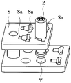
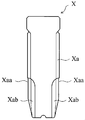
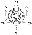
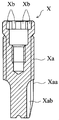
図1は本発明に係るフィクスチャーマウント固定具の一実施例を示す斜視図、図2は図1の正面図、図3は収納容器内のフィクスチャーに係合されたフィクスチャーマウントに図1のフィクスチャーマウント固定具が装着された状態を示す斜視図、図4は図3における収納容器が台座に保持され、フィクスチャーマウント固定具の垂下部に設けられている係止部が台座の収納容器保持穴に係止されている状態を示す斜視図、図5はセルフタッピング式インプラントフィクスチャーの一例を示す正面図、図6は図5の平面図、図7は図6のA−A線断面図、図8は図3における収納容器を示す斜視図、図9は図8の収納容器の部分断面斜視図、図10は図8の収納容器に図5のフィクスチャーを収納させた状態を示す斜視図、図11は図10のB−B線断面図、図12は図10における収納容器の部分断面正面図、図13は図3におけるフィクスチャーマウントの一例を示す斜視図、図14は図10における収納容器内に収納されたフィクスチャーに図13のフィクスチャーマウントを係合させた状態を示す斜視図、図15は本発明に係るフィクスチャーマウント固定具の他の実施例を示す斜視図、図16は図15のフィクスチャーマウント固定具が係止される収納容器の一例を示す斜視図、図17は図15のフィクスチャーマウント固定具が図13のフィクスチャーマウントに装着され、フィクスチャーマウント固定具の垂下部の下端に略等間隔で下方に突設されている突部が収納容器の側面に形成されている突起部間に係止されている状態を示す斜視図、図18は本発明に係るフィクスチャーマウント固定具の更に他の実施例を示す斜視図、図19は図18のフィクスチャーマウント固定具が係止される収納容器の一例を示す斜視図、図20は図18のフィクスチャーマウント固定具が図13のフィクスチャーマウントに装着され、フィクスチャーマウント固定具の垂下部に設けられている係止面が収納容器の側面に設けられている中心軸と平行な平面である係合部に係止されている状態を示す斜視図、図21は本発明に係るフィクスチャーマウント固定具の更に他の実施例を示す斜視図、図22は図21のフィクスチャーマウント固定具の底面図、図23は図21のフィクスチャーマウント固定具に装着されるフィクスチャーマウントの一例を示す斜視図、図24は図10における収納容器内に収納されたフィクスチャーに係合させた図23のフィクスチャーマウントに図21のフィクスチャーマウント固定具が装着されている状態を示す斜視図、図25はフィクスチャーマウントをフィクスチャーに固定する際に使用されるボルトの一例を示す正面図である。
Hereinafter, a fixture mount fixing cap according to the present invention will be described in detail with reference to the drawings.
1 is a perspective view showing an embodiment of a fixture mount fixture according to the present invention, FIG. 2 is a front view of FIG. 1, and FIG. 3 is a diagram of a fixture mount engaged with a fixture in a storage container. FIG. 4 is a perspective view showing a state in which the fixture mount fixture is mounted. FIG. 4 is a perspective view of the storage container shown in FIG. FIG. 5 is a front view showing an example of a self-tapping implant fixture, FIG. 6 is a plan view of FIG. 5, and FIG. 7 is a line AA in FIG. 8 is a perspective view showing the storage container in FIG. 3, FIG. 9 is a partial sectional perspective view of the storage container in FIG. 8, and FIG. 10 is a state in which the fixture in FIG. 5 is stored in the storage container in FIG. FIG. 11 is a perspective view showing FIG. FIG. 12 is a partial cross-sectional front view of the storage container in FIG. 10, FIG. 13 is a perspective view showing an example of the fixture mount in FIG. 3, and FIG. 14 is a fixture stored in the storage container in FIG. 13 is a perspective view showing a state where the fixture mount of FIG. 13 is engaged with the char, FIG. 15 is a perspective view showing another embodiment of the fixture mount fixture according to the present invention, and FIG. 16 is a fixture mount of FIG. FIG. 17 is a perspective view showing an example of a storage container to which the fixture is locked. FIG. 17 is a schematic view of the fixture mount fixture of FIG. 15 mounted on the fixture mount of FIG. FIG. 18 is a perspective view showing a state in which protrusions protruding downward at equal intervals are locked between protrusions formed on the side surface of the storage container, and FIG. 19 is a perspective view showing still another embodiment of the fixture mount fixture, FIG. 19 is a perspective view showing an example of a storage container to which the fixture mount fixture of FIG. 18 is locked, and FIG. 20 is a fixture mount of FIG. An engagement portion in which the fixture is mounted on the fixture mount of FIG. 13 and the locking surface provided at the hanging portion of the fixture mount fixture is a plane parallel to the central axis provided on the side surface of the storage container FIG. 21 is a perspective view showing still another embodiment of the fixture mount fixture according to the present invention, FIG. 22 is a bottom view of the fixture mount fixture of FIG. FIG. 23 is a perspective view showing an example of a fixture mount attached to the fixture mount fixture of FIG. 21, and FIG. 24 is a fixture stored in the storage container in FIG. FIG. 25 is a perspective view showing a state in which the fixture mount fixing tool of FIG. 21 is attached to the fixture mount of FIG. 23 engaged with the bracket. FIG. 25 is a bolt used when fixing the fixture mount to the fixture. It is a front view which shows an example.
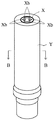
図面中、XはセルフタッピングねじXaの先端に形成された切り刃部Xaaに沿って溝部Xabが設けられているセルフタッピング式インプラントフィクスチャーであり、その口腔内側の内面には凹条溝Xbが形成されている。このようなフィクスチャーXとしては例えば図5〜図7の如き態様のものが使用でき、この態様では図6の如くフィクスチャーXの口腔内側の内面には6つの凹条溝Xbが形成されていて、これらはアバットメントを係合させたりフィクスチャー埋入用の治具を係合させるために使用されるものであり、例えば後述する図13のようなフィクスチャーマウントZを装着する場合、これらの6つの凹条溝Xbうちの3つの凹条溝Xbに係合させて装着させる。 In the drawing, X is a self-tapping implant fixture in which a groove portion Xab is provided along a cutting edge portion Xaa formed at the tip of a self-tapping screw Xa, and a concave groove Xb is formed on the inner surface of the oral cavity. Is formed. 5 to 7 can be used as such a fixture X. In this embodiment, six concave grooves Xb are formed on the inner surface of the oral cavity of the fixture X as shown in FIG. These are used to engage an abutment or a fixture embedding jig. For example, when mounting a fixture mount Z as shown in FIG. The six groove grooves Xb are engaged with and mounted on three groove grooves Xb.
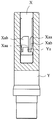
YはフィクスチャーXが収納される収納容器であり、例えば図8のような収納容器Yが使用できる。この収納容器Yには図9の部分断面図の如く、収納容器Y内の奥側に突起部Yaが形成されている。また図10〜図12の如くこの収納容器Y内にフィクスチャーXを収納させると、フィクスチャーXのセルフタッピングねじXaの先端の溝部Xabが収納容器Y内奥側に形成された突起部Yaに当接して、フィクスチャーXが回転不能な状態で収納されるのである。 Y is a storage container in which the fixture X is stored. For example, a storage container Y as shown in FIG. 8 can be used. As shown in the partial cross-sectional view of FIG. 9, the storage container Y is formed with a protrusion Ya on the back side in the storage container Y. When the fixture X is stored in the storage container Y as shown in FIGS. 10 to 12, the groove Xab at the tip of the self-tapping screw Xa of the fixture X is formed on the protrusion Ya formed on the inner side of the storage container Y. It abuts and the fixture X is stored in a non-rotatable state.
ZはフィクスチャーXの凹条溝Xbの奥部に形成されためねじ部へと繋がる貫通穴Zaを有するフィクスチャーマウントであり、その先端がフィクスチャーXの凹条溝Xbに係合される。このようなフィクスチャーマウントZとしては、図13の如き態様のものが使用できる。この態様では先端側に3つの突条部が等間隔に形成されている。このフィクスチャーマウントZとフィクスチャーXとを係合させるには、このフィクスチャーマウントZの先端を収納容器Yに収納されたフィクスチャーXに穿設された穴の口腔内側に押し当てて、フィクスチャーマウントZの先端側の3つの突条部がフィクスチャーXの6つの凹条溝Xbのうち3つの凹条溝Xbに挿入できる状態となるまでフィクスチャーマウントZを回転させた後に挿入させて図14の如く係合させるのである。その際に、フィクスチャーマウントZが押し当てられたフィクスチャーXが収納容器Y内で回転するとフィクスチャーマウントZを係合させることができないため、収納容器Y内の奥側にフィクスチャーXの溝部Xabに当接させる突起部Yaが形成されているのである。 Z is a fixture mount which is formed in the deep part of the groove Xb of the fixture X and has a through hole Za connected to the threaded part, and its tip is engaged with the groove Xb of the fixture X. As such a fixture mount Z, an embodiment as shown in FIG. 13 can be used. In this aspect, three protrusions are formed at equal intervals on the tip side. In order to engage the fixture mount Z with the fixture X, the tip of the fixture mount Z is pressed against the inside of the oral cavity of the hole formed in the fixture X stored in the storage container Y, Rotate the fixture mount Z until the three protrusions on the tip side of the char mount Z can be inserted into the three concave grooves Xb of the six concave grooves Xb of the fixture X. It is engaged as shown in FIG. At that time, if the fixture X against which the fixture mount Z is pressed rotates in the storage container Y, the fixture mount Z cannot be engaged, so that the groove portion of the fixture X on the back side in the storage container Y. A protrusion Ya to be brought into contact with Xab is formed.
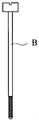
BはフィクスチャーマウントZをフィクスチャーXに固定する際にフィクスチャーマウントZの貫通穴Zaを通して螺入する図25に示すようなボルトであり、またSは収納容器Yを保持する台座である。 B is a bolt as shown in FIG. 25 which is screwed through the through hole Za of the fixture mount Z when the fixture mount Z is fixed to the fixture X, and S is a pedestal for holding the storage container Y.
次に本発明に係るフィクスチャーマウント固定具の構造について説明する。
1はボルトBを挿通させるボルト挿通用貫通穴であり、2は中央にこのボルト挿通用貫通穴1が穿設されている頂部である。本発明に係るフィクスチャーマウント固定具は、フィクスチャーXとフィクスチャーマウントZとをボルトBで固定する際に使用されるものであるから、ボルトBを挿入したり、ドライバー等の工具を挿入したりするためのボルト挿通用貫通穴1が頂部2に形成されているのである。
Next, the structure of the fixture mount fixture according to the present invention will be described.
3は頂部2から収納容器Yの側面に向けて垂下された垂下部である。本発明に係るフィクスチャーマウント固定具はこの垂下部3と前記のボルト挿通用貫通穴1が穿設されている頂部2とから構成されている。
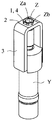
4はフィクスチャーマウントZの口腔内側の端部外面に設けられている正多角形状部Zbに係合させる係合穴である。本発明に係るフィクスチャーマウント固定具は、頂部2のボルト挿通用貫通穴1がフィクスチャーマウントZの口腔内側の端部外面に設けられている正多角形状部Zbに係合する係合穴4を有しているか及び/又は垂下部3がフィクスチャーマウントZの側面に設けられている中心軸と平行な平面部Zcに当接する係合面3aを有していて、フィクスチャーXと係合させたフィクスチャーマウントZに本発明に係るフィクスチャーマウント固定具を装着することによって、フィクスチャーXとフィクスチャーマウントZと本発明に係るフィクスチャーマウント固定具とを一体にすることができるのである。
Reference numeral 4 denotes an engagement hole that is engaged with the regular polygonal portion Zb provided on the outer surface of the inner end of the fixture mount Z. The fixture mount fixture according to the present invention has an engagement hole 4 in which a bolt insertion through
本発明に係るフィクスチャーマウント固定具の実施例としては先ず図1及び図2に示すような形状のものがある。このフィクスチャーマウント固定具は頂部2の中央に穿設されたボルト挿通用貫通穴1がフィクスチャーマウントZの口腔内側の端部外面に設けられている正多角形状部Zb(図3では正六角形状)に係合させる係合穴4となっている。
As an embodiment of the fixture mount fixture according to the present invention, there is a shape as shown in FIGS. In this fixture mount fixture, a regular polygonal portion Zb (a regular hexagon in FIG. 3) has a bolt insertion through
このフィクスチャーマウント固定具を実際に使用するには、先ず図14の如く収納容器Y内のフィクスチャーXの口腔内側の内面に形成されている凹条溝XbにフィクスチャーマウントZの先端側の突条部を係合させた状態で、フィクスチャーマウントZの口腔内側の端部外面に設けられている正多角形状部Zb(図14では正六角形状)にフィクスチャーマウント固定具の係合穴4を係合させて図3の如き状態にする。この図3の状態は、収納容器Y内のフィクスチャーXにフィクスチャーマウントZが係合され、更にそのフィクスチャーマウントZに本発明に係るフィクスチャーマウント固定具が係合されて、フィクスチャーXとフィクスチャーマウントZとフィクスチャーマウント固定具とが一体となっている。 In order to actually use this fixture mount fixing tool, first, as shown in FIG. 14, the fixture groove Z is inserted into the groove Xb formed on the inner surface of the inside of the oral cavity of the fixture X in the storage container Y. With the ridges engaged, the engagement holes of the fixture mount fixture are fitted into the regular polygonal portion Zb (regular hexagonal shape in FIG. 14) provided on the outer surface of the inner end of the fixture mount Z. 4 is engaged to obtain the state shown in FIG. In the state of FIG. 3, the fixture mount Z is engaged with the fixture X in the storage container Y, and the fixture mount fixture according to the present invention is further engaged with the fixture mount Z. The fixture mount Z and the fixture mount fixture are integrated.
次にこの図3の如き状態でフィクスチャーマウント固定具の下方に突設された3つの突部3baを図4に示すように台座Sに形成されている収納容器保持穴Saに形成されている3つの溝部にそれぞれ係止させる。これにより、フィクスチャーマウント固定具は台座Sに固定され回転不能な状態となり、更にこのフィクスチャーマウント固定具と一体となっているフィクスチャーマウントZ及びフィクスチャーXも回転不能となる。この状態で図25の如きボルトBをフィクスチャーマウントZの貫通穴Zaを通してフィクスチャーXに螺設されているめねじに螺入してフィクスチャーマウントZをフィクスチャーXに固定すれば、フィクスチャーマウントZは回転できないのでフィクスチャーXの溝部Xabが収納容器Y内の奥側の突起部Yaに強く当接して、フィクスチャーXが損傷するようなことがないのである。 Next, three protrusions 3ba projecting downward from the fixture mount fixture in the state as shown in FIG. 3 are formed in the storage container holding hole Sa formed in the base S as shown in FIG. Each of the three grooves is locked. As a result, the fixture mount fixture is fixed to the pedestal S and cannot be rotated, and the fixture mount Z and the fixture X integrated with the fixture mount fixture are also non-rotatable. In this state, when the bolt B as shown in FIG. 25 is screwed into the female screw screwed into the fixture X through the through hole Za of the fixture mount Z and the fixture mount Z is fixed to the fixture X, the fixture Since the mount Z cannot be rotated, the groove portion Xab of the fixture X does not come into strong contact with the rear projection portion Ya in the storage container Y, and the fixture X is not damaged.
本発明に係るフィクスチャーマウント固定具の他の実施例としては、図15の如きフィクスチャーマウント固定具がある。このフィクスチャーマウント固定具も図17の如くフィクスチャーマウントZの口腔内側の端部外面に設けられている正多角形状部Zb(図17では正六角形状)にフィクスチャーマウント固定具の係合穴4が係合される。 As another embodiment of the fixture mount fixture according to the present invention, there is a fixture mount fixture as shown in FIG. As shown in FIG. 17, the fixture mount fixture also has an engagement hole of the fixture mount fixture in a regular polygonal portion Zb (regular hexagonal shape in FIG. 17) provided on the outer surface of the inner end of the oral cavity of the fixture mount Z. 4 is engaged.
このフィクスチャーマウント固定具にも、垂下部3の下端に略等間隔で下方に突部3baが突設されているが、この突部3baは台座Sに係止させるものではなく、収納容器Yの側面に形成されている図16の如き突条の係合部Ybをこの突部3ba,3ba間に嵌合させるようにして係止させるのである。このようにフィクスチャーマウント固定具を収納容器Yに回転不能な状態で係止させることによって、フィクスチャーマウント固定具と一体となっているフィクスチャーマウントZ及びフィクスチャーXが回転不能となるのである。そして図17の如き状態の収納容器Yを手等で持ち、ボルトBをフィクスチャーマウントZの貫通穴Zaを通してフィクスチャーXに螺設されているめねじに螺入してフィクスチャーマウントZをフィクスチャーXに固定するのである。
This fixture mount fixture also has a protrusion 3ba projecting downward from the lower end of the drooping
また本発明に係るフィクスチャーマウント固定具の更に他の実施例としては、図18の如きフィクスチャーマウント固定具がある。このフィクスチャーマウント固定具も係合穴4を図20の如くフィクスチャーマウントZの口腔内側の端部外面に設けられている正多角形状部Zb(図20では正六角形状)に係合させるのである。 As still another embodiment of the fixture mount fixture according to the present invention, there is a fixture mount fixture as shown in FIG. This fixture mount fixture also engages the engagement hole 4 with a regular polygonal portion Zb (regular hexagonal shape in FIG. 20) provided on the outer surface of the inner end of the fixture mount Z as shown in FIG. is there.
このフィクスチャーマウント固定具も、台座Sに係止させるのではなく、収納容器Yに係止させるものである。このフィクスチャーマウント固定具では、図18の如く垂下部3に設けられている係止部3bが収納容器Yの側面に設けられている中心軸と平行な平面である係合部Ybに当接する係止面3bbとして設けられている。即ち図19の如く側面に中心軸と平行で対向する2つの平面である係合部Ybが設けられている収納容器Yを使用して、フィクスチャーマウント固定具にはこの平面を成す収納容器Yの係合部Yb,Ybにそれぞれ当接する2つの係止面3bb,3bbが設けられているのである。そして図20の如き状態にフィクスチャーマウント固定具を装着した後に収納容器Yを手等で持ち、ボルトBをフィクスチャーマウントZの貫通穴Zaを通してフィクスチャーXに螺設されているめねじに螺入すれば、フィクスチャーマウントZをフィクスチャーXに固定することができるのである。
This fixture mount fixture is also not locked to the base S but locked to the storage container Y. In this fixture mount fixture, as shown in FIG. 18, the engaging
本発明に係るフィクスチャーマウント固定具の更に他の実施例としては、図21の如きフィクスチャーマウント固定具がある。このフィクスチャーマウント固定具は、フィクスチャーマウントZの正多角形状部Zbと係合させるのではなく、図22の如きフィクスチャーマウント固定具の内部に形成された係合面3aを、図23の如きフィクスチャーマウントZの外面に設けられている中心軸と平行な平面部Zbに当接させることによって係合させるのである。なお図21,図22及び図24の頂部2の穴はボルトBを挿入したり、ボルトBを螺入する際に使用されるドライバー等を挿入するためのボルト挿通用貫通穴1である。
As still another embodiment of the fixture mount fixture according to the present invention, there is a fixture mount fixture as shown in FIG. This fixture mount fixture is not engaged with the regular polygonal portion Zb of the fixture mount Z, but an
このフィクスチャーマウント固定具は台座Sに係止させるものであり、図24の如き状態に装着されたフィクスチャーマウント固定具の3つの突部3baを、図4の実施例と同様に台座Sの収納容器保持穴Saに形成されている3つの溝部にそれぞれ係止させるのである。これにより、フィクスチャーマウント固定具は台座Sに固定され回転不能な状態となり、更にこのフィクスチャーマウント固定具と一体となっているフィクスチャーマウントZ及びフィクスチャーXも回転不能となる。この状態で図25の如きボルトBをフィクスチャーXの係合穴4及びフィクスチャーマウントZの貫通穴Zaを通して螺入してフィクスチャーXに螺設されているめねじにフィクスチャーマウントZをフィクスチャーXに固定するのである。 This fixture mount fixture is to be locked to the pedestal S, and the three projections 3ba of the fixture mount fixture mounted in the state as shown in FIG. 24 are connected to the pedestal S in the same manner as in the embodiment of FIG. Each of the three groove portions formed in the storage container holding hole Sa is locked. As a result, the fixture mount fixture is fixed to the pedestal S and cannot be rotated, and the fixture mount Z and the fixture X integrated with the fixture mount fixture are also non-rotatable. In this state, the bolt B as shown in FIG. 25 is screwed through the engagement hole 4 of the fixture X and the through hole Za of the fixture mount Z, and the fixture mount Z is fixed to the female screw screwed to the fixture X. It is fixed to Char X.
1 ボルト挿通用貫通穴
2 頂部
3 垂下部
3a 係合面
3b 係止部
3ba 突部
3bb 係止面
4 係合穴
X セルフタッピング式インプラントフィクスチャー
Xa セルフタッピングねじ
Xaa 切り刃部
Xab 溝部
Xb 凹条溝
Z フィクスチャーマウント
Za 貫通穴
Zb 正多角形状部
Zc 平面部
Y 収納容器
Ya 突起部
Yb 係合部
B ボルト
S 台座
Sa 収納容器保持穴
1 Bolt insertion through
3a Engagement surface
3b Locking part
3ba protrusion
3bb Locking surface 4 Engagement hole X Self-tapping implant fixture
Xa self-tapping screw
Xaa cutting edge
Xab groove
Xb Groove Z Fixture Mount
Za through hole
Zb regular polygon shape part
Zc Flat part Y Storage container
Ya protrusion
Yb engagement part B bolt S pedestal
Sa container holding hole
Claims (3)
中央に該ボルト(B)を挿通させるボルト挿通用貫通穴(1)が穿設されている頂部(2)と該頂部(2)から収納容器(Y)の側面に向けて垂下された垂下部(3)とから成り、該頂部(2)のボルト挿通用貫通穴(1)がフィクスチャーマウント(Z)の口腔内側の端部外面に設けられている正多角形状部(Zb)に係合する係合穴(4)を有しているか及び/又は該垂下部(3)がフィクスチャーマウント(Z)の側面に設けられている中心軸と平行な平面部(Zc)に当接する係合面(3a)を有していて、且つ該収納容器(Y)を保持する台座(S)に設けられた収納容器保持穴(Sa)又は該収納容器(Y)の側面に形成されている係合部(Yb)に係止される係止部(3b)が該垂下部(3)に設けられていることを特徴とするフィクスチャーマウント固定具。 The protrusion (Ya) formed on the inner side of the storage container (Y) is brought into contact with the groove (Xab) provided along the cutting edge (Xaa) formed at the tip of the self-tapping screw (Xa). The concave groove (Xb) of the fixture (X) is formed in the concave groove (Xb) formed on the inner surface of the oral cavity of the self-tapping implant fixture (X) that is non-rotatably stored in the storage container (Y). Engage the tip of the fixture mount (Z) with a through hole (Za) that is formed in the back of the groove (Xb) and connect to the threaded portion, and the through hole (Za) of the fixture mount (Z) When the fixture mount (Z) is fixed to the fixture (X) by a bolt (B) screwed through, the fixture mount (Z) is made non-rotatable with respect to the storage container (Y). A fixture mount fixture to be installed for maintenance,
A top part (2) in which a bolt insertion through hole (1) for inserting the bolt (B) is formed in the center, and a hanging part suspended from the top part (2) toward the side surface of the storage container (Y) (3), and the bolt insertion through hole (1) at the top (2) engages with a regular polygonal shape (Zb) provided on the outer surface of the end of the oral cavity of the fixture mount (Z). Engagement hole (4) and / or engagement where the hanging portion (3) abuts a flat surface portion (Zc) parallel to the central axis provided on the side surface of the fixture mount (Z) A storage container holding hole (Sa) provided in a pedestal (S) that has a surface (3a) and holds the storage container (Y), or is formed on a side surface of the storage container (Y). A fixture mount fixture, wherein the hanging portion (3) is provided with a locking portion (3b) to be locked to the joint portion (Yb).
Priority Applications (3)
| Application Number | Priority Date | Filing Date | Title |
|---|---|---|---|
| JP2008171821A JP5259274B2 (en) | 2008-06-30 | 2008-06-30 | Fixture mount fixture |
| EP09008545A EP2140831A1 (en) | 2008-06-30 | 2009-06-30 | Fixture mount fixing tool |
| US12/495,106 US8038443B2 (en) | 2008-06-30 | 2009-06-30 | Fixture mount fixing tool |
Applications Claiming Priority (1)
| Application Number | Priority Date | Filing Date | Title |
|---|---|---|---|
| JP2008171821A JP5259274B2 (en) | 2008-06-30 | 2008-06-30 | Fixture mount fixture |
Publications (2)
| Publication Number | Publication Date |
|---|---|
| JP2010011882A JP2010011882A (en) | 2010-01-21 |
| JP5259274B2 true JP5259274B2 (en) | 2013-08-07 |
Family
ID=41061331
Family Applications (1)
| Application Number | Title | Priority Date | Filing Date |
|---|---|---|---|
| JP2008171821A Expired - Fee Related JP5259274B2 (en) | 2008-06-30 | 2008-06-30 | Fixture mount fixture |
Country Status (3)
| Country | Link |
|---|---|
| US (1) | US8038443B2 (en) |
| EP (1) | EP2140831A1 (en) |
| JP (1) | JP5259274B2 (en) |
Family Cites Families (6)
| Publication number | Priority date | Publication date | Assignee | Title |
|---|---|---|---|---|
| US20080032263A1 (en) * | 2006-08-01 | 2008-02-07 | Vitali Bondar | Dental Implant System and Method |
| US6217332B1 (en) * | 1998-07-13 | 2001-04-17 | Nobel Biocare Ab | Combination implant carrier and vial cap |
| US6312260B1 (en) * | 1998-08-12 | 2001-11-06 | Nobel Biocare Ab | One-step threaded implant |
| US6561805B2 (en) | 1999-08-12 | 2003-05-13 | Nobel Biocare Ab | Universal implant delivery system |
| JP4818598B2 (en) * | 2004-09-10 | 2011-11-16 | 株式会社ジーシー | Screw-type implant fixture |
| JP2008125982A (en) * | 2006-11-24 | 2008-06-05 | Japan Medical Materials Corp | Package for storing dental implant |
-
2008
- 2008-06-30 JP JP2008171821A patent/JP5259274B2/en not_active Expired - Fee Related
-
2009
- 2009-06-30 US US12/495,106 patent/US8038443B2/en not_active Expired - Fee Related
- 2009-06-30 EP EP09008545A patent/EP2140831A1/en not_active Withdrawn
Also Published As
| Publication number | Publication date |
|---|---|
| US8038443B2 (en) | 2011-10-18 |
| US20090325124A1 (en) | 2009-12-31 |
| JP2010011882A (en) | 2010-01-21 |
| EP2140831A8 (en) | 2010-02-17 |
| EP2140831A1 (en) | 2010-01-06 |
Similar Documents
| Publication | Publication Date | Title |
|---|---|---|
| EP2377489B1 (en) | Housing container for implant fixture | |
| AU2013383332B2 (en) | Fastener head and complementary driver | |
| ES2441076T3 (en) | Threaded insert and vehicle component | |
| CN101641055A (en) | Orthodontic implant structure | |
| WO2011101807A4 (en) | Modular abutment system for tilted dental implants | |
| KR200455126Y1 (en) | Implants to prevent screw loosening | |
| WO2013186764A1 (en) | Triple lock abutment system | |
| KR20160029875A (en) | Dental implant apparatus and dental member for preventing loose | |
| JP5004644B2 (en) | Fixture storage container | |
| KR101028617B1 (en) | Implant Abutments | |
| KR101559823B1 (en) | Dental implant structure | |
| WO2011105685A2 (en) | Abutment screw for a dental implant | |
| KR20190002056U (en) | Angled implant that function as one-body | |
| WO2000015966A1 (en) | Improved structure of a multi-angle nut and its driving or unscrewing tool | |
| KR101491652B1 (en) | Dental implant with improved convenience screw and binding force | |
| JP5259274B2 (en) | Fixture mount fixture | |
| KR101598495B1 (en) | Multi-Fixture Driver for Use In Dentistry | |
| JP2010019393A (en) | Whirl stop device for tightening bolt | |
| KR200424940Y1 (en) | Fix Driver for Artificial Teeth | |
| US7090495B1 (en) | Dental implant screw and post system | |
| KR102357622B1 (en) | Dental solid type abutment | |
| KR101573520B1 (en) | Dental Implant | |
| TWI531357B (en) | Implant fixture removal device | |
| US11523884B2 (en) | Combined assembly for dental prosthesis | |
| JP5820767B2 (en) | Jig for removing dental abutment from implant fixture |
Legal Events
| Date | Code | Title | Description |
|---|---|---|---|
| A621 | Written request for application examination |
Free format text: JAPANESE INTERMEDIATE CODE: A621 Effective date: 20110527 |
|
| A131 | Notification of reasons for refusal |
Free format text: JAPANESE INTERMEDIATE CODE: A131 Effective date: 20130108 |
|
| TRDD | Decision of grant or rejection written | ||
| A01 | Written decision to grant a patent or to grant a registration (utility model) |
Free format text: JAPANESE INTERMEDIATE CODE: A01 Effective date: 20130423 |
|
| A61 | First payment of annual fees (during grant procedure) |
Free format text: JAPANESE INTERMEDIATE CODE: A61 Effective date: 20130424 |
|
| FPAY | Renewal fee payment (event date is renewal date of database) |
Free format text: PAYMENT UNTIL: 20160502 Year of fee payment: 3 |
|
| R150 | Certificate of patent or registration of utility model |
Ref document number: 5259274 Country of ref document: JP Free format text: JAPANESE INTERMEDIATE CODE: R150 Free format text: JAPANESE INTERMEDIATE CODE: R150 |
|
| RD03 | Notification of appointment of power of attorney |
Free format text: JAPANESE INTERMEDIATE CODE: R3D03 |
|
| R250 | Receipt of annual fees |
Free format text: JAPANESE INTERMEDIATE CODE: R250 |
|
| LAPS | Cancellation because of no payment of annual fees |